PR402 Installation Guide Rev.D - Roger
PR402 Installation Guide Rev.D - Roger
PR402 Installation Guide Rev.D - Roger

Create successful ePaper yourself
Turn your PDF publications into a flip-book with our unique Google optimized e-Paper software.
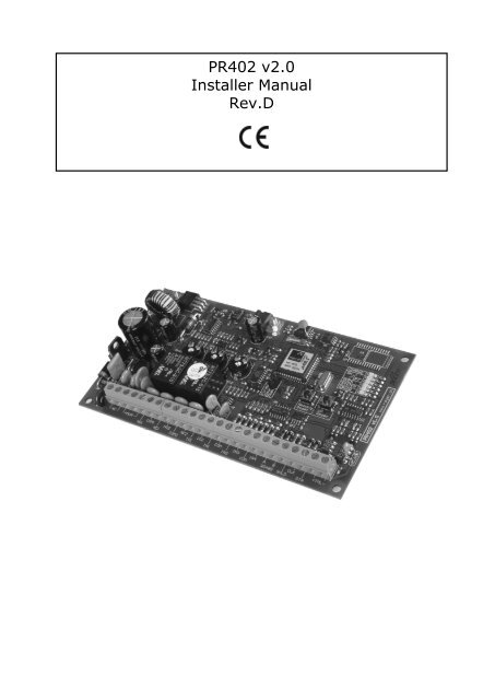
<strong>PR402</strong> v2.0Installer Manual<strong>Rev</strong>.D
<strong>PR402</strong> <strong>Installation</strong> <strong>Guide</strong> <strong>Rev</strong>.D 12/4/2012IntroductionThis document contents minimum information required for electrical connections, installation andinitial tests of <strong>PR402</strong> access controller.<strong>Installation</strong>The <strong>PR402</strong> module can be installed in any metal or plastic enclosure which guarantees adequateprotection from dust, water and moisture. Also, it should assure required temperature, ingressprotection and security. All wirings must be made before module will be powered on. Battery (ifused) should be connected once the <strong>PR402</strong> is powered by AC.Factory new unit is configured to address ID=00 and has MASTER PIN (1234) and MASTER card(delivered together with the new device), in necessary new MASTER card/PIN/address can beprogrammed manually during Memory Reset procedure which is explained later in this document.The MASTER card/PIN can be used for initial testing of the controller - the single use of MASTERcard/PIN activates REL1 output for approx. 4s, while double, consecutive, use of MASTER card/PINchanges controller’s arming mode and switches IO1 output to reverse state.Note: The MASTER card delivered with new controller will be recognized as MASTER one when readon the PRT series reader configured to RACS mode.All devices working in given access system and connected to the same RS485 communication busshould have common minus (common GND). This can be achieved by connecting all minuses frompower supplies located in given system with separate, additional, wire or by connecting each powersupply minus with earth however the second solution might crate problems when electricalpotentials of the earth is not the same in different parts of electrical installation.Note: It is forbidden to short positive outputs (DC+) from various power supplies and other DCoutputs available in the system.Setting addressBefore you connect controller to RS485 communications bus it should be programmed with adequateaddress (ID number=00..99). Controller’s address can be set manually during Memory Resetprocedure or from PC computer.Note: Connecting two or more controllers with the same address will cause communications conflicton the communication bus.If you connect controller to separate COM port it is not necessary to change its address becausethere is no risk of conflict in address. Also, in such a case, you can use PR Master program to searchCOM port for newly connected controller and eventually, change its address. Once the controller hasright address it can be disconnected from COM port and installed in designated system.Power supplyController can be powered from AC source which delivers 18-22VAC/30VA power; it can be ME-1metal enclosure (from <strong>Roger</strong>) with built-in 40VA transformer or another AC source which providesrequired voltage and power.Optionally, <strong>PR402</strong> can be supplied directly from 12VDC, in this case 12VDC supply voltage should beconnected to +ACC- terminals which are normally used for reserve battery (for details see wiringdiagram below). Additionally, when supplied from 12VDC, B.Supp. programming jumper (on <strong>PR402</strong>board) should be closed (jumper on). When powered from 12VDC, <strong>PR402</strong> must not be connected toAC supply nor operate with reserve battery - reserve supply should be assured by 12VDC systemused to supply controller.Note: Always carefully calculate wire gauge used to power <strong>PR402</strong> from 12VDC supply system, notethat amount of current required by controller can be as high as 2A and depends on total currentsourced from AUX and TML terminals. The <strong>PR402</strong> board itself consumes less then 100mA.- 2 -
<strong>PR402</strong> <strong>Installation</strong> <strong>Guide</strong> <strong>Rev</strong>.D 12/4/2012Reserve battery<strong>PR402</strong> controller is capable to operate with reserve battery however presence of battery is notobligatory to run controller. When installed, battery provides two important features:Delivers power supply in case of AC network failureProvides an extra current in time moments when total current consumption exceedscapability of built-in AC supply circuit (1.5A)<strong>PR402</strong> was originally designed for operation with 12V/7Ah battery nevertheless it can work withother batteries with higher or lower capacitance as well. When in standby, reserve battery ischarged with constant 300mA current until it reaches 13.8V level which indicates that battery is fullycharged. During battery charging, DC output voltage (available on AUX and TML terminals) mayvary from 11.5-13.8V and depends on battery charging phase. Controller checks periodically batterylevel and when it drops below 12V indicates Low Battery or when drops below 11.5V indicatesBattery Failure. In case when system runs on reserve battery (when AC supply is lost) and batterylevel drops below 10V, battery is automatically disconnected from the controller; battery isautomatically re-connected when AC supply returns. The maximum current which can be deliveredby battery is electronically limited to 2.5A.Note: It is not possible to start controller on battery itself (without AC supply) - to start operation<strong>PR402</strong> requires AC supply however once started it can run later on battery itself.Charging current adjustmentWhen required battery charging current can be adjusted in 100-500mA range. In order to setrequired charging current connect battery to controller and using adequate screwdriver rotate POT1potentiometer, use battery which are partly discharged. Charging current should be observed usingmultimeter connected in series with battery plus or minus.Note: It is forbidden to set battery charging current below 100mA level because in this casecharging current control is not guaranteed.Connection of door lockIn most cases door locks are inductive type loads and generate strong voltage surges whenswitching to off state. This phenomenal can corrupt electronic circuits and/or change its behaviour(e.g. hung-up). In order to protect <strong>PR402</strong> system from these effects, every inductive load (like doorlock or any other coil e.g. relay coil) should be protected with silicon diode (e.g. 1N4007) connected- 3 -
<strong>PR402</strong> <strong>Installation</strong> <strong>Guide</strong> <strong>Rev</strong>.D 12/4/2012as close as possible to device it protects. Also, door locks should be wired using separate pair ofwires connected directly to the source of power.Inputs<strong>PR402</strong> offers four programmable inputs (IN1, IN2, IN3 and IN4). All of them have the same electricstructure and can be configured as NO or NC. Each input is internally biased to supply plus (+12V)through 5.6kΩ resistor, this makes that +12V is observed on the not connected (floating) input.The NO type input goes active when shorted to supply minus (GND), ff input is left unconnected orshorted to +12V it represents passive (normal) state.The NC line in passive (normal) state should be connected to supply minus (GND), it becomes active(triggered) when connection with GND is discontinued. If input is left unconnected or shorted to+12V it is in active (triggered) state.Note: If required, inputs can be connected together - still they can be programmed to differentfunctions.Relay outputs<strong>PR402</strong> has two, programmable, relay outputs (REL1 and REL2). Each of them offers oneNO/NC/COM contact 24V/1.5A with built-in voltage surge protection.Note: Appling voltages above 30V to REL1/REL2 terminals will damage electronic components usedto protect relays’ contacts, this will corrupt functionality of relay output.In normal state NC terminal is shorted to COM while NO remains isolated. When active, NO isshorted to COM while NC is isolated. When controller is not supplied or supplied with voltage belowits minimum level, relay outputs remain not active.Transistor outputsThere are two transistor outputs IO1 and IO2 available on <strong>PR402</strong> controller, both have identicalelectrical structure. When passive (normal state) transistor outputs represent high impedance,when active (triggered state) outputs short to supply minus (GND). Each output can sink max. 1ADC to GND; switched voltage must be 15VDC or less. The IO1 and IO2 are internally protected fromcurrents above 1A.RS485 communication busThe RS485 serial communications interface in <strong>PR402</strong> consist of three terminals: A, B and SHLD.Electrically, it represents RS485 standard however there are two important changes with respect tocommon RS485 standard:daisy chain structure is not required- 4 -
<strong>PR402</strong> <strong>Installation</strong> <strong>Guide</strong> <strong>Rev</strong>.D 12/4/2012terminating resistors are not requiredGenerally, free topology of communication bus is allowed, comm. bus cables can form “three’’, “star”or any combination of them however closed loops are forbidden. It is recommended to use UTPcable for A and B lines nevertheless any type of signal cables is accepted as well. The use ofshielded cables should be limited to those installation were strong electromagnetic interferences areexpected.The maximum length of cable run between communication interface and individual controller orbetween CPR32-SE network controller (if installed in system) and individual controller, or betweencommunication interface and CPR32-SE network controller must not exceed 1200m. For longerdistances use UT-3 or UT-4 interfaces. Using two UT-3 units communication distances can beextended by next 1200m, while for UT-4 distance is not limited because it uses computer network.Connecting readers and extension modulesAccess terminals (readers) and extension modules (e.g. XM-2, XM-8) can be connected to controllerthrough CLK and DTA lines. Controller can operate either with <strong>Roger</strong> access terminals or with anyother readers which support Wiegand or Magstripe data output protocols. Any type of signal cablecan be used for CLK and DTA lines. Each device connected to controller through CLK/DTA line musthave its individual address (0..15) however this rule is valid only for devices using RACS Clock andData interface.Note: Normally, the maximum guaranteed cable length between controller and any other deviceconnected to CLK/DTA line is limited to 150m. When using RACS Clock and Data interface in mostcases communication will run satisfactory for up to 500m distances.For best card reading results readers should be installed on non-metal surfaces. When installed onmetal structures the reading range can be reduced up to 50%. This effect can be limited byinstalling the reader in some distance above metal construction (for this purpose you can use nonmetalspacer min. 10mm thick between controller and supporting surface). Readers should beinstalled on at least 0.5m distance one from each other; also, two readers should not be alignedalong the same geometrical axe.Connecting Wiegand and Magstripe readersFollow schematic drawing below when connecting Wiegand or Magstripe readers to <strong>PR402</strong> controller.Note, that for operation with these types of readers you must use PR Master program to configurecontroller (by default controller if pre-configured for RACS Clock and Data).Memory ResetMemory Reset procedure enables erasing of current settings and returning to default factorysettings. Full procedure also allows to program new MASTER card/PIN as well as new address of thecontroller. After Memory Reset procedure, the controller automatically enters normal working mode.Simplified Memory Reset procedure (firmware 2.18.2 or newer)- 5 -
<strong>PR402</strong> <strong>Installation</strong> <strong>Guide</strong> <strong>Rev</strong>.D 12/4/2012Simplified Memory Reset restores default settings and automatically sets controller address ID=00.MASTER card and PIN cannot be configured. This procedure does not require connection of PRTseries external terminal.Remove connections to CLK and DTA terminals of the controllerConnect CLK terminal with DTA terminalPress and hold MEMORY RESET button until LED 4 on the controller pulsatesRelease MEMORY RESET buttonDisconnect CLK and DTA terminalsAfter a few seconds the controller shall restart automatically and switch to normal modeSimplified Memory Reset procedure (firmware older than 2.18.2)Simplified Memory Reset restores default settings and enables programming of new MASTER cardwhile controller address is automatically configured as ID=00. This procedure requires connection ofany PRT series reader. The reader must be configured as RACS Clock&Data terminal with ID0 or ID1and connected through CLK and DTA lines.Press and hold MEMORY RESET button until LED OPENthe controller pulsatesRelease MEMORY RESET buttonRead any card at the reader — this will be a new MASTER card(green) on the reader or LED 4 onAfter a few seconds the controller shall restart automatically and switch to normal modeFull Memory Reset procedureFull Memory Reset restores default settings and enables programming of new MASTER card, MASTERPIN and controller ID address. This procedure requires connection of PRT series reader with keypad(e.g. PRT12LT). The reader must be configured as RACS Clock&Data terminal with ID0 or ID1 andconnected through CLK and DTA lines.Press and hold MEMORY RESET button until LED OPENthe controller pulsatesRelease MEMORY RESET button(green) on the reader or LED 4 onEnter new MASTER PIN (3-6 digits) followed with the [#] key or skip this step and press onlythe [#] keyRead any card at the reader — this will be a new MASTER card or skip this step and pressonly the [#] keyEnter two digits (in range of 00 to 99) by means of keypad – this will be new ID address orskip this step and press only the [#] key so the default ID=00 could be assignedAfter a few seconds the controller shall restart automatically and switch to normal modeAfter Memory Reset, controller resumes its work with default factory settings and entered address.You can then initially test its operation using the MASTER card or PIN (if available). Using theMASTER card/PIN once activates the REL1 output for 4 seconds (LED OPEN is on for the timewhen REL1 is active). Using of MASTER card/PIN twice switches the IO1 output to the opposite stateand changes arming mode (LED STATUS changes its colour).Note: If current address of the controller is hardware type (FixedID) then address entered withinMemory Reset procedure is ignored.Firmware upgradeDuring manufacturing process controller is programmed with latest version of firmware,nevertheless it can be later upgraded with newer versions as they are released. <strong>Roger</strong> design teamcontinuously work on enhancements so the new firmware versions are released quite often (everynew firmware version is published on www.roger.pl). Our customers are advised to register at website so <strong>Roger</strong> will let inform when new versions are ready for download. The new firmware can be- 6 -
<strong>PR402</strong> <strong>Installation</strong> <strong>Guide</strong> <strong>Rev</strong>.D 12/4/2012downloaded without removal of the controller from it original place of installation. The detaileddescription of firmware upgrade procedure can be found in Firmware upgrade.pdf available atwww.roger.pl.New firmware can be uploaded to controller through RS485 communication bus from the <strong>Roger</strong>ISPv3 program. Once the controller is upgraded it should be fully reconfigured. Also, if the unit wasalready working in the system it is necessary to update its version setting in access system databasecommand:…Networks/Controllers/Commands/Restart controller and verify version...Note: Whenever you upgrade firmware in controller it is necessary to upgrade PR Master programas well. For most update firmware/software visit www.roger.plTable: Terminal assignmentsTerminal+ACC-AC+AUX-REL1-NOREL1-COMREL1-NCREL2-NOREL2-COMREL2-NCIN1COMIN2IN3COMIN4IO1IO2RS485 ARS485 BSHLDCLKDTA+TML-FunctionReserve batteryAC supply input, 18-22V/30VAUnswitched DC output 12VDC/1A, AUX (-) internally shorted with GND, outputcurrent internally limitedREL1 output, normally open contact, 24V/1.5AREL1 output, common contact, 24V/1.5AREL1 output, normally closed contact, 24V/1.5AREL2 output, normally open contact, 24V/1.5AREL2 output, common contact, 24V/1.5AREL2 output, normally closed contact, 24V/1.5AIN1 input, internally pulled up to supply plus through 5.6kΩ resistorInput common, internally shorted with supply minus (GND)IN1 input, internally pulled up to supply plus through 5.6kΩ resistorIN1 input, internally pulled up to supply plus through 5.6kΩ resistorInput common, internally shorted with supply minus (GND)IN1 input, internally pulled up to supply plus through 5.6kΩ resistorIO1 transistor output, 15VDC/1.0AIO2 transistor output, 15VDC/1.0ARS485 communication bus, line ARS485 communication bus, line BRS485 cable shieldReader/extension modules interface, line CLOCKReader/extension modules interface, line DATAUnswitched DC output 12VDC/200mA dedicated to supply external reader and/orextension modules, TML(-) internally shorted with GND, output current internallylimitedTable: Technical specificationParameterSupply voltagePower consumptionValueNominal 18VAC, min./max. range 18-22VAC30VA- 7 -
<strong>PR402</strong> <strong>Installation</strong> <strong>Guide</strong> <strong>Rev</strong>.D 12/4/2012DistancesEnvironmental class(according to EN50131-1)DimensionsWeightApprovalsBetween controller and reader or extension module: max. 150 mBetween controller and communications interface or CPR32-SE networkcontroller: 1200mClass I, Indoor-General, temperature: 5°C- +40°C, relative humidity: 10to 95% (non-condensing)151 X 87 mm~ 100gCE- 8 -
<strong>PR402</strong> <strong>Installation</strong> <strong>Guide</strong> <strong>Rev</strong>.D 12/4/2012Ordering information<strong>PR402</strong><strong>PR402</strong>-BRDME-1ME-2ZMPR-1RM-2RM-2-BRDXM-2XM-2-BRDUT-2UT-2USBUT-4<strong>PR402</strong> access controller with ME-1 metal enclosure<strong>PR402</strong> module, board onlyMetal enclosure with 40VA transformerMetal enclosure with 80VA transformerAssembly kit for ME-2 enclosure, allows for assembly of up to four <strong>PR402</strong>boards into single ME-2 enclosure, also suitable for extension modulesRelay module with plastic enclosure, the RM-2 offers two relays with oneNO/NC contact 24V/1.5A rated, relay contacts are protected by surge arresters,each relay can be triggered by applying supply plus or minus, the maximumamount of current required to trigger relay is less then 5mA, two LEDs toindicate triggering of relevant relayRM-2 module, board onlyInput/output addressable extension module with plastic enclosure, digitalcommunication according to RACS Clock and Data protocol, two NO/NC inputsand two relay outputs, each relay offers one NO/NC contact 24V/1.5A/24Vrated, relay contacts protected by surge arresters, two LEDs to indicatetriggering of relevant relayXM-2 module, board onlyRS232-RS485 communication interfaceUSB-RS485 communication interfaceEthernet-RS485/RS232 communication interfaceContact<strong>Roger</strong> sp. j.82-416 GosciszewoGosciszewo 59Tel.: +48 (55) 272 01 32Fax: +48 (55) 272 01 33e-mail: biuro@roger.pl- 9 -
<strong>PR402</strong> <strong>Installation</strong> <strong>Guide</strong> <strong>Rev</strong>.D 12/4/2012- 10 -