LoadMaster 80
LoadMaster 80
LoadMaster 80
- No tags were found...

You also want an ePaper? Increase the reach of your titles
YUMPU automatically turns print PDFs into web optimized ePapers that Google loves.
Application Analysis WorksheetPhone: 1-<strong>80</strong>0-554-8466Website: www.linearactuators.comHorizontal ApplicationsFor selection assistance, fax to your local Danaher Motion distributor or Danaher Motion at 1-<strong>80</strong>0-445-0329.DateCompanyAddressCity State Zip CodeNameTitle Phone ( )Fax ( )Rapidtrak * supporting the loadUse for applications in which the profile is used horizontallyand the load is supported by the profile. Photocopy as needed.Application RequirementsDetermine: Eccentric (moment) loadsTotal operating loadSpeed of operationInput torque to size the prime moverM y = F x x H aF xF zH aLfLH yF zM xM x = F z x H yMeasurements1. Load Fz = ____________(lbs.)2. Speed = _____________(inches per second)3. Stroke length = ________(ft.)(2,3,4,6,9,12,15,18,21,22')4. Eccentric load measurements Hy = ___________(ft.)5. Acceleration = _______(ft./sec 2 )*acceleration = (max speed ÷ time to speed)6. Motor RPM = ___________7. Max distance between mounting feet (Lf) = _________________(ft.)Figure ARapidtrak * not supporting the loadFor applications in which the profile is used horizontally and the load is not supported by the profile, refer to Figure B. Photocopy as needed.Application RequirementsDetermine: Eccentric (moment) loadsTotal operating loadSpeed of operationInput torque to size the prime moverMeasurements1. Axial force Fx = ____________(lbs.)2. Speed = _____________(inches per second)3. Stroke length = ________(ft.)4. Eccentric load measurements Ha = ___________(in.)5. Acceleration = _______(in/sec 2 )**acceleration = (max speed ÷ time to speed)6. Motor RPM = ___________7. Max distance between mounting feet (Lf) = ___________(ft.)8. Coefficient of friction of external bearings (if used) = _________________M yFigure BloadF xH aPlease include drawings, comments or additional information on separate pages.C-6©2003 Danaher Motion. Printed in the U.S.A. The specifications in this publication are believed to be accurate and reliable.However, it is the responsibility of the product user to determine the suitability of Thomson products for a specific application.While defective products will be replaced without charge if promptly returned, no liability is assumed beyond such replacement.** Trademark of Danaher Motion. DANAHER MOTION is registered in the U.S. Patent and Trademark Office and in other countries.
Phone: 1-<strong>80</strong>0-554-8466Website: www.linearactuators.comApplication Analysis WorksheetVertical ApplicationsFor selection assistance, fax to your local Danaher Motion distributor or Danaher Motion at 1-<strong>80</strong>0-445-0329DateCompanyAddressCity State Zip CodeNameTitle Phone ( )Fax ( )Use for applications in which the profile is used vertically (Fig. C)Photocopy as needed.(_____ft.)H a(_____ft.)Application RequirementsDetermine: Eccentric (moment) loadsTotal operating loadSpeed of operationInput torque to size the prime moverF aH aload(_____lbs.)L cF a (_____lbs.)loadM a = H a x F aMeasurements1. Axial force Fz = ____________(lbs.)2. Speed = _____________(inches per second)3. Stroke length = ________(ft.)4. Eccentric load measurements or Ha = ___________(in.)5. Acceleration = _______(in/sec 2 )**acceleration = (max speed ÷ time to speed)6. Motor RPM = ___________7. Max distance between mounting feet (Lf) = ___________(ft.)8. Coefficient of friction of external bearings (if used) = _________________Additional Comments about application or sketch:Single saddleFigure CTwin saddlesPlease include drawings, comments or additional information on separate pages.*©2003 Danaher Motion. Printed in the U.S.A. The specifications in this publication are believed to be accurate and reliable.However, it is the responsibility of the product user to determine the suitability of Thomson products for a specific application.While defective products will be replaced without charge if promptly returned, no liability is assumed beyond such replacement.C-7* Trademark of Danaher Motion. DANAHER MOTION is registered in the U.S. Patent and Trademark Office and in other countries.
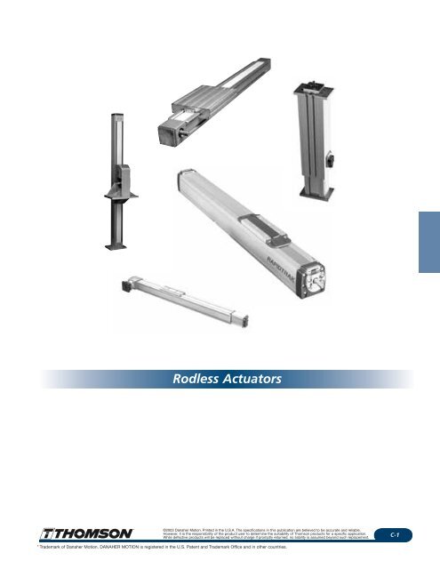
Rapidtrak * Rodless AcuatorsThomson Rapidtrak * Rodless ActuatorsThe Rapidtrak ® linear actuator is the newest addition to the DanaherMotion Linear Products line. This new actuator complements the Electrak ®line of actuators by providing stroke lengths of 2 feet to 22 feet, speedsto more than 16 feet per second and carry loads up to 1650 lbs.These actuators are modular and can accept any NEMA 56-C face motoror gearbox. Provisions are also available for adding feedback encodersand custom mounting servo or step motors. Actuators may also easily bemechanically synchronized for load sharing or simultaneous motion.The Rapidtrak linear actuator provides guided linear motion using eithera ball screw or belt drive and a saddle that rides along the top of theactuator to carry the load. The housing protects the ball screw or beltfrom contamination and reduces maintenance requirements. Theseactuators are ideal for industrial or material handling applicationsbecause of the high speed and long stroke length capabilities. Thereare numerous advantages to the Rapidtrak design:Phone: 1-<strong>80</strong>0-554-8466Website: www.linearactuators.com• Speed – speeds of over 16 feet per second are achievable dependingon the load, prime mover, and gearbox. These higher speeds greatlyincrease the application versatility of the actuator.• Stroke length – stroke lengths are available up to 22 feet.Optional limit switch packages allow the length to be set within thephysical limits of the actuator.• Load support – loads up to 1650 lbs. can ride directly on the carriage.This eliminates the need for ways or bearings in many cases and providesa complete, compact package.• Modular – the actuator uses a mounting flange for the motor whichpermits the interchange of NEMA C-faced motors, gearboxes, clutches,and brakes. This allows the unit to be customized to specificapplication requirements.• Shorter overall length – the extended and retracted lengths arethe same. This permits a smaller envelope for the actuator and allowsit to be applied in more size restricted applications.Applications include material handling and press line automation.Ball screw actuator with prism supportTG xx KBelt drive actuator with prism supportTG xx BBall screw drive actuator with ball guide supportTF xx KBelt drive actuator with ball guide supportTF xx BC-8©2003 Danaher Motion. Printed in the U.S.A. The specifications in this publication are believed to be accurate and reliable.However, it is the responsibility of the product user to determine the suitability of Thomson products for a specific application.While defective products will be replaced without charge if promptly returned, no liability is assumed beyond such replacement.** Trademark of Danaher Motion. DANAHER MOTION is registered in the U.S. Patent and Trademark Office and in other countries.
Phone: 1-<strong>80</strong>0-554-8466Website: www.linearactuators.comRapidtrak * Rodless ActuatorsThe ball bearing screw drive provides precisepositioning and high load carrying capability.It can provide saddle speeds up to 49 inchesper second and drive axial loads up to 1100lbs. High stiffness and repeatability characterizethe ball screw versions. Stroke lengths to22 feet are standard.Ball bearing screw drive units provide highload capability and high precision.• Speeds up to 49 inches per second.• Thrust loads up to 1100 lbs.• Suitable for mounting in any position –horizontal, vertical, upside down oron an incline.• Low torque required to drive the load due tohigh efficiency ball bearing drive.• Linear bearings provide low stick slip forprecise positioning and ease of moving load.Low profile saddle is predrilled toaccept the mounting feet of anotherunit mounted at right angles andprovide easy X-Y motion.Tensioning station on cover strip helpseliminate stretching of the strip toextend life.Magnetic cover strip protects thebelt and ball guides fromcontaminants and effectivelyseals the profile from theenvironment.Ball screw support allowshigher speeds with longerstroke actuators.Ball guides for higherloads, lower stick-slip.Slots for mounting feetor limit switches.High efficiency ball bearing screwminimizes the torque needed todrive the load.Trouble free, reliable motion controlThe new M-family of Rapidtrak rodlessactuators provides several solutions for longtrouble-free operation.• Belt Drive units for operation up to 200inches per second.• Ball Screw Drive units for pushing up to1100 lb and precision positioning.• Ball Guide units for applications needinglow stick-slip or saddle loads to 1650 lb.• Prism Guide units for high shock, vibrationor applications needing adjustablepreload.Common features of all actuator models• Ball Guides provide high load capabilityand low friction for precise positioning.• Saddles have a new low profile design withthe bolt pattern set up for mountinganother Rapidtrak in the perpendicular axis.• New modified slots for easier mounting.Allows material to be blown or washed out.• Mounting Feet are modular for ease ofinstallation.• Limit Switch Brackets mount to the newmodified slots for easy installation andadjustment.• Cover Band protects the ball screw andball guide from contaminants and keepslubrication inside.• Cover Band Stretcher extends thelife of the cover band and eliminates theneed to tension it as it wears.• Magnetic Strips hold the cover band inplace during operation to protectthe ball screw and ball guide.• Drive Flanges are available for servo, step,AC and DC motors.• Stroke Lengths are available up to 22 feet.• Rodless design allows the load to bemounted directly to the saddle, eliminatesthe need for support bearings and reducesthe overall length of the unit.• Custom Systems are available with themotor and control mounted and tested atthe factory. Contact your local ThomsonLinear Products salesperson or distributor.*©2003 Danaher Motion. Printed in the U.S.A. The specifications in this publication are believed to be accurate and reliable.However, it is the responsibility of the product user to determine the suitability of Thomson products for a specific application.While defective products will be replaced without charge if promptly returned, no liability is assumed beyond such replacement.C-9* Trademark of Danaher Motion. DANAHER MOTION is registered in the U.S. Patent and Trademark Office and in other countries.
Rapidtrak * Design FeaturesPhone: 1-<strong>80</strong>0-554-8466Website: www.linearactuators.comThe belt drive provides high speed operationover long stroke lengths with moderate loadcarrying capability. Saddle speeds up to 200inches per second are possible and thrustloads up to 275 lbs. Stroke lengths of the beltdrive units range from 2 to 22 feet. While ballscrew drive units may be mounted in anydirection, belt drive actuators are notrecommended for vertical applications.Belt drive units provide high speeds at longstroke lengths.• Speeds up to 200 inches per second.• Speed not affected by stroke length.• Linear bearings provide low stick-slip formore precise positioning and ease ofmoving heavy loads.• Belt drive units are less affectedby contamination.• Double shaft design makes it easyto synchronize two units or to attachan encoder.Tensioning station on cover strip helpseliminate stretching of thestrip to extend life.Magnetic cover strip protectsthe belt and ball guides fromcontaminants and effectivelyseals the profile from theenvironment.Low profile saddle is predrilled toaccept the mounting feet of anotherRapidtrak mounted at right angles.Provides easy X-Y motion.Slots for mounting feetor limit switches.Tensioning unit on thenon-driven end of the beltdrive actuator allowstensioning of the belt.Ball guides for higher loads,lower stick-slip.Drive shaft on belt drive unit is doubleended. This allows driving the unit fromeither side, easily connecting two driveshafts together or connecting anencoder to the other shaft.Four sizes of self-supportingaluminum profilesBelt is steel reinforced polyurethane for light weight,low stretch and high strength characteristics. It is atiming belt design to eliminate slip and provide accuratepositioning.Heavy duty load supportBelt Drive50100 mm7555Prism supportBall guide support505575100Ball Screw DriveTG xx BTF xx BRapidtrak is now available in differentprofile sizes for different load and enveloperequirements. There are also four differentcombinations of ball screw or belt drive,prism guide or ball guide support.Prism supportBall guide supportTG xx KTF xx KC-10©2003 Danaher Motion. Printed in the U.S.A. The specifications in this publication are believed to be accurate and reliable.However, it is the responsibility of the product user to determine the suitability of Thomson products for a specific application.While defective products will be replaced without charge if promptly returned, no liability is assumed beyond such replacement.** Trademark of Danaher Motion. DANAHER MOTION is registered in the U.S. Patent and Trademark Office and in other countries.
Phone: 1-<strong>80</strong>0-554-8466Website: www.linearactuators.comRapidtrak * ApplicationsThe new M-family of Rapidtrak rodlessactuators can be used in horizontal, vertical,inclined or upside down positions. Theversatility is enhanced with the differentprofile sizes, the ability to use AC, DC, stepperor servo motors with ball screw drives or beltdrive models and a choice of either ballguides for low friction and high loads orprism guides for high shock or vibrationapplications.Rapidtrak componentsmay be combined tocreate x-y tablesor lifts forhandling largeor bulky items.This application shows thatRapidtrak actuators may becombined for a variety ofuses. Two parallel unitssupport a vertical unit in apalletizing application.Rapidtrak units may be mountedby the profile and have the saddleprovide the motion or may bemounted by the saddle and havethe profile provide the motion.*©2003 Danaher Motion. Printed in the U.S.A. The specifications in this publication are believed to be accurate and reliable.However, it is the responsibility of the product user to determine the suitability of Thomson products for a specific application.While defective products will be replaced without charge if promptly returned, no liability is assumed beyond such replacement.C-11* Trademark of Danaher Motion. DANAHER MOTION is registered in the U.S. Patent and Trademark Office and in other countries.
Rapidtrak * ApplicationsPhone: 1-<strong>80</strong>0-554-8466Website: www.linearactuators.comThe width of an assembly fixture is adjusted by the touchof a button. When combined with a programmable indexerseveral positions can be preset and recalled in any order.The Rapidtrak units are mechanically synchronized tomaintain the parallel sides of the fixture.Rapidtrak units can also be used as parts feeders. Thisillustration shows a unit feeding round bars into a weldingprocess. The advantage of the Rapidtrak is the easilycontrollable rate of feed that may beachieved with feedback and a variablespeed control on the motor.A Rapidtrak is used for slicing products precisely with themotion controlled by a servo motor and control. This easilyallows changes in the operation for a variety of materialsto be processed.For this welding fixturethe Rapidtrak unit ismounted upside down andthe fixture plate is fastened tothe bottom of the profile. The armthat supports the welding head is attached tothe sleigh and bends around the profile. The metalplates to be welded are placed over the positioning pinsand the welding head is moved along the length.C-12©2003 Danaher Motion. Printed in the U.S.A. The specifications in this publication are believed to be accurate and reliable.However, it is the responsibility of the product user to determine the suitability of Thomson products for a specific application.While defective products will be replaced without charge if promptly returned, no liability is assumed beyond such replacement.** Trademark of Danaher Motion. DANAHER MOTION is registered in the U.S. Patent and Trademark Office and in other countries.
Phone: 1-<strong>80</strong>0-554-8466Website: www.linearactuators.comHow to SelectRapidtrak is a self-supporting, modular linear motion device that can beused horizontally, vertically or upside down. It is capable of strokes up to22 feet and speeds over 16 feet per second. The new M family ofproducts is available in three different profile sizes with your choice ofball guide or prism guide for support and either belt drive or ball screwdrive for positioning the load. Ball guides provide low friction and lowstick-slip for applications requiring precise positioning and allow smallermotors to drive the load. Prism guides have high shock and vibrationtolerance and are relatively unaffected by environmental contaminants.Ball screw drives are used for high precision, high loads, high efficiency orvertical applications. Belt drives are used for high speeds (over 16 feetper second) and are not affected by critical speed as is a ball screw.The following guide will help you select the correct Rapidtrak for yourapplication. Worksheets are included on pages C-6 and C-7 for your use.The measurements required for sizing a Rapidtrak are shown on theworksheet.Step 1. Load and MountingHorizontalThe maximum customer load (Fz) is determined by the profile selected, thesaddle configuration (A or C), support type (ball guide or prism) and thenumber and spacing of the supports or mounting feet (Lf), not by theoverall length of the unit. The deflection of the Rapidtrak mustnot exceed0.08"/10'. The curves in Fig. D (page C-14) show the relationship betweenthe spacing of the supports and the load capability of the profiles.Additional mounting feet may be required to adequately support the load.VerticalIf the Rapidtrak is in a vertical application or is just pushing a load,then the maximum load is Fx and is shown in Table A.Table AFx Max My Max Mx MaxModel Description (lbf) (lbf-in) (lbf-in)TP05 M50 belt drive-prism guide 88 168 44TG55K M55 prism guide - ball screw drive 220 203 79TG55B M55 prism guide - belt drive 88 203 79TF55B M55 ball guide - ball screw drive 220 424 44TG75K M55 ball guide - belt drive 88 185 56TG75B M75 prism guide - ball screw drive 550 708 398TF75K M75 prism guide - belt drive 198 708 398TF75B M75 ball guide - ball screw drive 550 1150 159TG100K M75 ball guide - belt drive 198 708 132TG100B M100 prism guide - ball screw drive 1100 2433 1062TF100K M100 prism guide - belt drive 275 2389 885TF100B M100 ball guide - ball screw drive 110 3540 477TF100B M100 ball guide - belt drive 275 2478 442Acceleration Formulas and Force DefinitionFxFz= the axial load or thrust of the Rapidtrak= the load that is supported by the Rapidtrak profile. The amount ofthe load that the Rapidtrak will support is determined by the sizeof the profile and the distance between the mounting feet.Facc = the acceleration forces acting on the loadAcceleration= (V–Vo)/t or = (V 2 –Vo 2 )/2XV = top speedVo = initial speed (usually zero if starting from rest or the speed beforeaccelerating or decelerating)t = time to reach top speedX = distance travelled to reach top speedXo = initial positionFtot = sum of all forces acting on the actuator – load, friction, andacceleration. The prime mover must be sized based on the F totcalculation.Rapidtrak * Selection GuideFigure BM taH aF rdBall Screw DriveF aF xF rdM xH xBelt DriveStep 2. Eccentric LoadsHorizontalThe eccentric loads must be calculated to determine the maximumresultant forces acting on the system that will deflect or bind theRapidtrak. The formulas for calculating the eccentric loads are below andcan be used in conjunction with the Eccentric Load Chart – Table A todetermine if the results fall within the acceptable ranges.If the load is carried by the saddle, F z = direct load and is the same valueas in Step 1.Hy = distance the load is from the centerline of the saddle in feetEccentric load calculation MxMx = Fz x Hy _________lbf-ftIf the value for Mx exceeds the capability of all of the profiles, an externalsupport such as a liner bearing and shafting or non-driven Rapidtrak maybe used to help support the load. The maximum distance between adriven and non-driven Rapidtrak should not be more than 15 inches.VerticalIf the load is supported by external bearings, is just pushing the load or isin a vertical application, then the eccentric loads act along the axis of theRapidtrak and you must calculate the value for eccentric load My.Fz = axial load and is the same value as in Step 1Ha = distance of the load from the top of the saddleMy = Ha x Fa ________lbf-ftFyLfF yM taM a*©2003 Danaher Motion. Printed in the U.S.A. The specifications in this publication are believed to be accurate and reliable.However, it is the responsibility of the product user to determine the suitability of Thomson products for a specific application.While defective products will be replaced without charge if promptly returned, no liability is assumed beyond such replacement.C-13* Trademark of Danaher Motion. DANAHER MOTION is registered in the U.S. Patent and Trademark Office and in other countries.
Rapidtrak * Selection GuidePhone: 1-<strong>80</strong>0-554-8466Website: www.linearactuators.comFigure D – Maximum Distance between mounting feet (L f )Distance between Supports (inches)160140120100<strong>80</strong>604020M055 Ball Screw Drive00 20 40 60 <strong>80</strong> 100Load on the Saddle (lb.)Distance between Supports (inches)M055 Belt Drive2502001501005000 20 40 60 <strong>80</strong> 100Load on the Saddle (lb.)Distance between Supports (inches)160140120100<strong>80</strong>6040M075 Ball Screw Drive20000 100 200 300 400 5000 100 200 300 400 500 600Load on the Saddle (lb.)Load on the Saddle (lb.)Distance between Supports (inches)30025020015010050M075 Belt Drive600Step 3. Total Force CalculationAll of the friction and acceleration forces acting on the Rapidtrak arecalculated and added to determine the total force needed to move the load.Ftot Run = Fx + Fµ+ Facc + RFtot Start = Fx + Fm + Facc + (R x 2.5)Fa = 0 for horizontal applications, the same value as in Step 1 in verticalapplicationsFµ = Fz x 0.21 for horizontal applications with the load supported on thesaddle with prism guideFµ = Fz x 0.02 for horizontal applications with the load supported on thesaddle with ball guideFµ = My x 0.21 for vertical applications with prism guideFµ = My x 0.02 for vertical applications with ball guideAcceleration forceFacc = (load / 32.2ft/sec 2 ) x accelerationAcceleration= maximum speed / time to speed or= (maximum speed) 2 / ( 2 x distance to speed)Distance between Supports (inches)30025020015010050M100 Ball Screw & Belt Drive00 200 400 600 <strong>80</strong>0 1000Load on the Saddle (lb.)Table ESaddle friction force (R) per saddle (lb)M55 M75 M100Ball guided 1.12 4.5 4.5Prism guided 6.74 9 9C saddles = 2 ˘ RScrew supports = 1/2 ˘ R per supportEx: M75 prism, C saddle, one screw support, R = 22.5 lb.1200C-14©2003 Danaher Motion. Printed in the U.S.A. The specifications in this publication are believed to be accurate and reliable.However, it is the responsibility of the product user to determine the suitability of Thomson products for a specific application.While defective products will be replaced without charge if promptly returned, no liability is assumed beyond such replacement.** Trademark of Danaher Motion. DANAHER MOTION is registered in the U.S. Patent and Trademark Office and in other countries.
Phone: 1-<strong>80</strong>0-554-8466Website: www.linearactuators.comFigure F – Critical SpeedsScrew Speed (RPM)Screw Speed (RPM)Screw Speed (RPM)35003000250020001500100050035003000250020001500100050035003000250020001500100050000M055 Ball Screw Drive2 4 6 8 10Stroke (feet)M075 Ball Screw Drive005 10Stroke (feet)Screw Support None Single DoubleM100 Ball Screw Drive00 5 10 15 20Stroke (feet)Screw Support None Single Double1225Rapidtrak * Selection GuideStep 4. Speed of OperationThe ball screw maximum speed is dependent on the lead of the screwand the maximum RPM shown in the speed chart. Internal supportsfor the screws will allow higher speeds at longer lengths as shown onthe chart. Belt drive versions are capable of speeds up to 200" persecond but are limited to lower loads and should not be used invertical applications (see Fig. F).Step 5. Prime Mover SelectionThe input torque calculations will be required for motor sizing.Motors can be AC, DC, servo, stepper or synchronous. The formulasfor calculating the input torque for either a ball screw drive or a beltdrive are listed below. You will use the Ftot from the Total ForceCalculations.Input Torque Calculations (at motor)Ball screw drive (direct drive)Running Td = Ftot Run x L/ 60.32 = _____lbf-ftStarting Tstart = Ftot Start x L / 60.32 = ______lbf-ftNote: L = screw lead in inchesBelt driveRunning Td = (Ftot Run x .0919 for M100) = ________lbf-ft= (Ftot Run x .0679 for M75) = ________lbf-ft= (Ftot Run x .0548 for M55) = ________lbf-ftStarting Tstart = (Ftot Start x .0919 for M100) = ________lbf-ft= (Ftot Start x .0679 for M75) = ________lbf-ft= (Ftot Start x .0548 for M55) = ________lbf-ftNote: If a reducer is used, divide the above torque values by thereduction and by .7 (reducer efficiency) to obtain torque at the motor.This is a good time to calculate the size of the reducer or motor that isneeded to drive the load. You will use the results of the input torquecalculations just completed.Minimum Horsepower Required= (Td x Motor RPM ) / 5250 = _______hpVerify that the motor selected can handle the starting torque (Tstart)of the applicationReducer Calculation (Optional)Reduction I = (motor rpm) / (Rapidtrak rpm)Note: when sizing prime mover special attention should be madeto motor inertia and system requirements. Contact the factory foradded input.*©2003 Danaher Motion. Printed in the U.S.A. The specifications in this publication are believed to be accurate and reliable.However, it is the responsibility of the product user to determine the suitability of Thomson products for a specific application.While defective products will be replaced without charge if promptly returned, no liability is assumed beyond such replacement.C-15* Trademark of Danaher Motion. DANAHER MOTION is registered in the U.S. Patent and Trademark Office and in other countries.
Rapidtrak * Selection GuidePhone: 1-<strong>80</strong>0-554-8466Website: www.linearactuators.comStep 6. Part Number SelectionT F 10 K 259 – C35 S 256Version ................TBall Guided ......................................FPrism Guided ..................................GProfile Size 100mm ................1075mm ..................0755mm ..................06“L” dimension in cm..................X X XNo Screw Support ....XSingle Support ....................................SDouble Support ..................................D“A” Saddle ..........Standard Single Saddle..............................................A 0 0Belt Drive ............................................B“C” Saddle ..........Lc (c/c distance for 2 saddles in cm)........................C X X 3Ball Screw + Composite NutM100 (min. distance in cm) ....................................C 3 5 3(M55 Only) ......................................CM75 (min. distance in cm) ......................................C 2 5 3Non-Driven ..........................................NM55 (min. distance in cm) ....................................C 2 0 3,Ball Screw + Ball Nut ..........................K4Ball Screw + Preloaded Ball Nut 1Ball Screw Drive 2 Lead Tolerance Class Ball Screw DesignationM100............10 mm ....................T9 ..........................................2510 ........................109 (opt) 5....................25 mm ....................T9 ..........................................2525 ........................259 (std)M75..............12.7 mm..................T9 ..........................................0702 ........................729 (std)....................20 mm ....................T7 ..........................................2020 ........................207 (opt) 5M55..............5.08 mm..................T9 ..........................................0605 ........................659 (std)....................20 mm ....................T7 ..........................................1620 ........................207 (opt) 5Belt Drive....................................PitchM100............176 mm/rev ..........................................................................................176M75..............130 mm/rev ............................................................................................130M55..............105 mm/rev ..........................................................................................105Example:LTF07B130–A00X241Ball guided, 75mm profile, belt drive, 130mm belt pitch, “A” saddle,standard single saddle, no screw support, 241cm profile lengthBall Screw DriveStep 7. Other Design ConsiderationsLimit SwitchesEnd of stroke limit switches are mandatory for all Rapidtrak actuators.The limit switches prevent the saddle from striking the end of the of thehousing which can result in extensive damage to the unit. The strokelength of each actuator has two inches of overtravel included in eachdirection to allow the actuator to coast to a stop after the limit switchesare tripped. A two foot stroke actuator actually has 2'4" of stroke toallow for the overtravel. Brackets are included for mounting standardelectro-mechanical limit switches to the profile. Limit switches arecustomer provided or may be ordered along with the Rapidtrak.Part numbers for the limit switches are included in the options section.Load Holding BrakeDue to the high efficiency of the ball screw drive a load holding brake isrequired in vertical applications to prevent the load from backdriving thescrew. This can be added to the motor or installed between the motor andthe Rapidtrak unit.Step Motor DriveStep motors should not be used in applications in which the load canbackdrive the Rapidtrak. If the motor stalls, the torque falls to zero andthe load may backdrive.Step 8. OptionsThe following options can be ordered by part number toaccommodate your specific application.• Mounting flange for the motor (p. C-25)• Mounting kits (p. C-33)• Encoder mounting flange (p. C-28)• Couplings (p. C-28)• Limit switch brackets (p. C-29)• Limit switches (p. C-29)1Consult factory if pre-loaded ball nut is required.2Consult factory if non-standard lead or tolerance class is required.3Represents "L c " dimension on Saddle/Stroke Length drawings.4M55, Belt Drive, ball guide min. distance is 25 cm.5Non-standard option; longer lead time required, consult factory.LBelt DriveC-16©2003 Danaher Motion. Printed in the U.S.A. The specifications in this publication are believed to be accurate and reliable.However, it is the responsibility of the product user to determine the suitability of Thomson products for a specific application.While defective products will be replaced without charge if promptly returned, no liability is assumed beyond such replacement.** Trademark of Danaher Motion. DANAHER MOTION is registered in the U.S. Patent and Trademark Office and in other countries.
Phone: 1-<strong>80</strong>0-554-8466Website: www.linearactuators.comDimensions - Ball Screw DriveSaddles/Stroke LengthsA SaddleDALCEC SaddleD* CE*For C Saddle (dual) configuration, L = L (A Saddle) + L c Driven saddleUndriven saddleL cL cScrew Minimum SaddleBall Screw Drive Supports A C D E L c G L* Length0 "C"+19.528 Stroke length 8.031 8.031 13.7<strong>80</strong> "A"+"L c " "C"+16.063 12.047Ball Guide (TF10K) 1 "C"+21.575 Stroke length 9.055 9.055 13.7<strong>80</strong> "A"+"L c " "C"+18.110 12.0472 "C"+25.512 Stroke length 11.024 11.024 13.7<strong>80</strong> "A"+"L c " "C"+22.047 12.047M100 0 "C"+19.134 Stroke length 8.031 8.031 13.7<strong>80</strong> "A"+"L c " "C"+16.063 12.047Prism Guide (TG10K) 1 "C"+20.394 Stroke length 8.662 8.662 13.7<strong>80</strong> "A"+"L c " "C"+17.323 12.0472 "C"+24.331 Stroke length 10.630 10.630 13.7<strong>80</strong> "A"+"L c " "C"+21.260 12.0470 "C"+15.984 Stroke length 6.457 6.457 9.840 "A"+"L c " "C"+12.913 8.583Ball Guide (TF07K) 1 "C"+19.449 Stroke length 8.189 8.189 9.840 "A"+"L c " "C"+16.378 8.5832 "C"+23.386 Stroke length 10.157 10.157 9.840 "A"+"L c " "C"+20.315 8.583M75 0 "C"+15.984 Stroke length 6.457 6.457 9.840 "A"+"L c " "C"+12.913 8.583Prism Guide (TG07K) 1 "C"+20.000 Stroke length 8.465 8.465 9.840 "A"+"L c " "C"+16.929 8.5832 "C"+24.016 Stroke length 10.472 10.472 9.840 "A"+"L c " "C"+20.945 8.583M55 Ball Guide (TF06K) 0 "C"+14.390 Stroke length 5.827 5.827 7.870 "A"+"L c " "C"+11.654 7.244Prism Guide (TG06K) 0 "C"+14.390 Stroke length 5.827 5.827 7.870 "A"+"L c " "C"+11.654 7.244GLMaximum allowable distance between supportsCritical speedFy (LBS)1<strong>80</strong>015751Fy (LBS)2251<strong>80</strong>5135013511259002904566754503Max. Lf032 40 48 56 64 72 <strong>80</strong> 88 96(in)2254020 40 60<strong>80</strong> 100 120 140 160Figure 1: General installation instructionsMax. Lf(in)40 <strong>80</strong> 120 160 200 240L =inThe curves show max. allowed distance (Lf) between every mounting point fordifferent loads (Fy) for different units.1 TF10K 3 TF07K 5 TF06K2 TG10K 4 TG07K 6 TG06K*©2003 Danaher Motion. Printed in the U.S.A. The specifications in this publication are believed to be accurate and reliable.However, it is the responsibility of the product user to determine the suitability of Thomson products for a specific application.While defective products will be replaced without charge if promptly returned, no liability is assumed beyond such replacement.C-19* Trademark of Danaher Motion. DANAHER MOTION is registered in the U.S. Patent and Trademark Office and in other countries.
Dimensions - Belt Drive ActuatorsPhone: 1-<strong>80</strong>0-554-8466Website: www.linearactuators.comM504.625 (117.25) Min.Limit Switch Actuation Point2.00 (50) Min.Coast Allowance0.414 (10.5) Max.1.968±0.020(50±0.5)4.724±0.020 (120±0.5)1.968±0.020(50±0.5)LStroke2.362±0.020(60±0.5)1/4 - 20 Helicoils (3)0.420 (10.7) DP.5.215 (132.5) Min.Limit Switch Actuation Point2.00 (50) Max.Coast Allowance1.989(50.5)Min.1.18±0.02(30±0.5)ł1.26 +0.004 (ł32.00 +0.1 ) Typ. (2)-0.000 -010 - 32 UNF (4) on Equally Spacedł1.575 ±0.020 (ł40 ±0.5) B.C. Typ. (2)1.772 (45) Max.0.433 (11.5) Max.Adjustment screws0.125 +.000.002(3.2 .05)Type (2)ł0.472–0.020(12–0.5) Typ. (2)2.424 (61) Max.Type (2)1.125–0.020(28–0.5) Typ (2)TOT 0.938–.020(24–.5)Incl. Rad.2.323±0.020(59±0.5)0.984±0.020(25±0.5)0.492±0.009(12.5±0.2)Type (2)0.87(22)Ref.1.06(27)Ref.ł0.437+0.0005-0.0(ł11.1k6) Typ. (2)0.134 (3.4) Min.Type (2)2.461 (62.5) Max.0.984–0.020(25–0.5)1.989 (50.5) Max.0.98 (25) Ref.1.988 (50.5) Max.0.10 (2.5) Ref.0.14 (3.5) Ref.Saddle/Stroke Lengths’L’ = Stroke + 14.56 (369.82)StrokeFrictionComponentCoefficientRolling Element .005Teflon on Steel .04Steel on Steel .58Steel on Steel (lubr.) .15Aluminum on Steel .45Copper on Steel .22Brass on Steel .19Size Support Weight CalculationA SaddleM50 Prism 1.56 lb + L (cm)* 0.55 lb*See page C-19 for saddle dimensions.C-20©2003 Danaher Motion. Printed in the U.S.A. The specifications in this publication are believed to be accurate and reliable.However, it is the responsibility of the product user to determine the suitability of Thomson products for a specific application.While defective products will be replaced without charge if promptly returned, no liability is assumed beyond such replacement.** Trademark of Danaher Motion. DANAHER MOTION is registered in the U.S. Patent and Trademark Office and in other countries.
Phone: 1-<strong>80</strong>0-554-8466Website: www.linearactuators.comDimensions - Belt Drive ActuatorsM55, M75, M100AESaddle*FAGDC(Max)H(Overall)BBB∅ .98(25)∅ .59 (15)∅ .59 (11)2.50(63.5)Ref.20 (5)4.724(120)1.575(40)2.50(63.5)Ref.20 (5)4.567(116)M100 End View M75 End View M55 End View1.142(29)1.18(30).08 (2)3.386(86).984(25)M75.706and(17.9)M100.625(ø15.9)Keyway DetailDimensions in inches (mm)Profile Load DimensionsSize Support A B C D E F G H0.94 1.93 2.28 5.75 1.97 2.76 2.46 2.72M55 Prism (24) (49) (58) (146) (50) (70) (62.5) (69)0.94 1.93 2.28 5.75 1.97 2.76 2.46 2.72M55 Ball Guide (24) (49) (58) (146) (50) (70) (62.5) (69)0.96 2.99 3.39 9.96 2.44 3.39 3.33 3.64M75 Prism (24.5) (76) (86) (253) (62) (86) (84.5) (92.5)0.96 2.99 3.39 9.96 2.44 3.39 3.33 3.64M75 Ball Guide (24.5) (76) (86) (253) (62) (86) (84.5) (92.5)1.02 3.66 4.23 10.12 2.76 3.39 4.31 4.67M100 Prism (26) (93) (107.5) (257) (70) (86) (109.5) (118.5)1.02 3.66 4.23 10.12 2.76 3.39 4.31 4.67M100 Ball Guide (26) (93) (107.5) (257) (70) (86) (109.5) (118.5).1885(4.8).478(12.1).120(3.0)M55.433(ø11.1)*See page C-22 for saddle dimensions.Size Support Weight CalculationA SaddleC SaddleM55 Prism 6.61 lb + L (cm)* 0.9 lb 9.04 lb + L (cm) *0.9 lbM55 Ball Guide 6.83 lb + L (cm)* 1.17 lb 9.48 lb + L (cm) *1.17 lbM75 Prism 9.26 lb + L (cm)* 1.48 lb 12.57 lb + L (cm) *1.48 lbM75 Ball Guide 10.36 lb + L (cm)* 1.94 lb 14.77 lb + L (cm) *1.94 lbM100 Prism 13.01 lb + L (cm)* 2.43 lb 18.3 lb + L (cm) *2.43 lbM100 Ball Guide 12.57 lb + L (cm)* 3.22 lb 17.42 lb + L (cm) *3.22 lb*See page C-22 for saddle dimensions.*©2003 Danaher Motion. Printed in the U.S.A. The specifications in this publication are believed to be accurate and reliable.However, it is the responsibility of the product user to determine the suitability of Thomson products for a specific application.While defective products will be replaced without charge if promptly returned, no liability is assumed beyond such replacement.C-21* Trademark of Danaher Motion. DANAHER MOTION is registered in the U.S. Patent and Trademark Office and in other countries.
Dimensions - Belt Drive ActuatorsPhone: 1-<strong>80</strong>0-554-8466Website: www.linearactuators.comSaddles/Stroke LengthsA SaddleHDALCEJC SaddleHDGL*CEJDriven saddleUndriven saddleLcLcMinimumSaddleBelt Drive A C D E L c G H J L* LengthM100 Ball Guide (TF10B) "C"+21.929 Stroke length 9.646 10.237 13.7<strong>80</strong> "A"+"L c " 2.756 3.386 "C"+13.740 12.047(557) (245) (260) (350) (70) (86) (349) (306)M100 Prism Guide (TG10B) "C"+20.748 Stroke length 9.055 9.646 13.7<strong>80</strong> "A"+"L c " 2.756 3.386 "C"+12.559 12.047(527) (230) (245) (350) (70) (86) (319) (306)M75 Ball Guide (TF07B) "C"+18.268 Stroke length 7.677 8.661 9.843 "A"+"L c " 2.441 3.386 "C"+10.513 8.583(464) (195) (220) (250) (62) (86) (267) (218)M75 Prism Guide (TG07B) "C"+18.268 Stroke length 7.677 8.661 9.843 "A"+"L c " 2.441 3.386 "C"+10.513 8.583(464) (195) (220) (250) (62) (86) (267) (218)M55 Ball Guide (TF06B) "C"+18.425 Stroke length 8.071 8.465 9.843 "A"+"L c " 1.968 2.756 "C"+11.811 9.213(468) (205) (215) (250) (50) (70) (300) (234)M55 Prism Guide (TG06B) "C"+16.063 Stroke length 6.693 7.4<strong>80</strong> 7.870 "A"+"L c " 1.968 2.756 "C"+9.449 7.244(408) (170) (190) (200) (50) (70) (240) (184)Maximum Allowable Distance Between SupportsFy (LBS)1<strong>80</strong>0Fy (LBS)22515751<strong>80</strong>13501125900675213135904545032 40 48 56 64 72 <strong>80</strong> 88 96Max. Lf(in)450225020 40 60Max. Lf(in)<strong>80</strong> 100 120 140 160Figure 1: General installation instructionsThe curves show max. allowed distance (L f ) between every mounting pointfor different loads (F y ) for different units.1 TF10B, TG10B 3 TG07B 5 TG06B2 TF07B 4 TF06BC-22©2003 Danaher Motion. Printed in the U.S.A. The specifications in this publication are believed to be accurate and reliable.However, it is the responsibility of the product user to determine the suitability of Thomson products for a specific application.While defective products will be replaced without charge if promptly returned, no liability is assumed beyond such replacement.** Trademark of Danaher Motion. DANAHER MOTION is registered in the U.S. Patent and Trademark Office and in other countries.
Phone: 1-<strong>80</strong>0-554-8466Website: www.linearactuators.comDimensions - SaddlesA SaddlesC Saddle uses (2) A SaddlesA (6) Heli-CoilG (Saddle Thickness)CB(Max)DHEDHDimensions in inches (mm)Rapidtrak Saddle type A B C D E G HM100 A 3/8 – 16 3.85 2.362 2.795 12.047 .63 3.90(97.7) (60) (71) (306) (16) (99)M75 A 5/16 – 18 3.15 2.362 2.087 8.583 .59 2.835(<strong>80</strong>) (60) (53) (218) (15) (72)M55 A 10 – 32 2.087 1.614 1.496 7.244 .47 2.32(53) (41) (38) (184) (12) (59)M55 A 10 – 32 2.087 1.614 1.496 9.212 .47 3.305Ball Guided, Belt only (TF06B) (53) (41) (38) (234) (12) (84)*©2003 Danaher Motion. Printed in the U.S.A. The specifications in this publication are believed to be accurate and reliable.However, it is the responsibility of the product user to determine the suitability of Thomson products for a specific application.While defective products will be replaced without charge if promptly returned, no liability is assumed beyond such replacement.C-23* Trademark of Danaher Motion. DANAHER MOTION is registered in the U.S. Patent and Trademark Office and in other countries.
Rapidtrak AccessoriesPhone: 1-<strong>80</strong>0-554-8466Website: www.linearactuators.comM509600-171-003 (two included)1.63(41) Ref.1.86(47) Ref.Bolt 1/4–20Clamp, MountingBase, MountingIncludes:(1) Base, mounting (165-9041)(2) Clamp, mounting (263-9120)(4) Bolt 1/4 -20(4) Washer 1 /4"1.00±0.010(25.4±0.3)3.875±0.020(98.4±0.5)0.88(22) Ref.0.875(22.2) Ref.M55, M75, M100ABM100/M75/M55DCEFGTop ViewJHIClamp type Part number A B C D E F G H I JM100 9600-174-005 .866 (22) .787 (20) 3/8 – 16 3.937 (100) 5.591 (142) 7.4<strong>80</strong> (190) M10 2.362 (60) 3.937 (100) 2.362 (60)M75 9600-174-011 .591 (15) .591 (15) 5/16 – 18 2.953 (75) 4.193 (106.5) 5.276 (134) M8 2.362 (60) 3.150 (<strong>80</strong>) 2.362 (60)M55 9600-174-012 .433 (11) .591 (15) 1/4 – 20 1.73 (44) 2.992 (76) 3.94 (100) M5 1.614 (41) 2.756 (70) 1.732 (44)Kits for Mounting One Rapidtrakto the Saddle of AnotherM55, M75, M100Mounting Configurations.393"Max. 10mmABCDIncludes: (2) Bolts(2) ClampsClamp type Part number A B C D EM100 9600-264-002 Ø.413 (10.5) M10 .906 (23) 1.811 (46) 1.043 (26.5) —M75 9600-264-003 Ø.335 (8.5) M8 .591 (15) 1.181 (30) .689 (17.5) —M55 9600-264-004 Ø.217 (5.5) M5 .492 (12.5) .984 (25) .602 (15.3) —C-24©2003 Danaher Motion. Printed in the U.S.A. The specifications in this publication are believed to be accurate and reliable.However, it is the responsibility of the product user to determine the suitability of Thomson products for a specific application.While defective products will be replaced without charge if promptly returned, no liability is assumed beyond such replacement.** Trademark of Danaher Motion. DANAHER MOTION is registered in the U.S. Patent and Trademark Office and in other countries.
Phone: 1-<strong>80</strong>0-554-8466Website: www.linearactuators.comRapidtrak AccessoriesMounting FlangesStandard (included with M100 and M75 units)(9600-456-004).67(17)5/16-18 UNCbolt holes (4)M140 (-14) ActuatorM90 (-09) Actuator45°2.50 (63.5).625(15.88)Dia.nom.2.54(65ø)Dia.B.C.4.50(114.3)Dia.nom. 5.875(149.2)Dia.B.C.6.50(165)Dia..177 (4.5).197 (5) .188 (4.78) x 1.68 (19.9) keyway3/8-16UNC tap (4)@ 90° each.517 (13.13)9600-456-004Includes:(1) Flange (456-9037)(4) 5/16-18 boltsHigh humidity kit9600-456-027For direct drive with NEMA 56C-face motor(9600-456-003).67(17)4.25 (108)3/8-16 UNC bolts (8)4.50(114.3)Dia.Access hole.50 (12.7) Dia.3,75(95.25)Dia.Ref.4.50(114.3)Dia.5.875(149.2)Dia.B.C.6.50(165)Dia.45˚M90 or M140 Actuatorw/Mtg. Flange(9600-456-004)Drive Coupling(Order separatelyseepage 23).67(17)“C” faceMotor.406 (10.3) Dia. hole thru(4) @ 90˚ each (Actuator flange)(4) @ 45˚ each (Motor flange)9600-456-003Includes:(1) Flange (456-9038)(8) 3/8-16 boltsx 1.00” longFor direct drive with NEMA 34 step motor(9600-456-006)3.687 (93.7)1.0(25.4).406 (10.3) Dia. hole thru(4) @ 90˚ each6.50(165.1)Dia.5.875(149.23)Dia.B.C.4.50(114.3)Dia.2.878(73.1)Dia.3.875(98.43)Dia.B.C.4.625(117.5)Dia.45˚.15 (3.8).10 (2.54).50 (12.7) .48 (12.2)#10-32UNF 2B ST1 thread.50 (12.7) mun deep (4) @ 90 ˚ each9600-456-006Includes:(1) Flange (456-9045)(4) 3/8-16 bolts x 1.00” long(4) 10-32 UNF 2A screwsx .500” long*©2003 Danaher Motion. Printed in the U.S.A. The specifications in this publication are believed to be accurate and reliable.However, it is the responsibility of the product user to determine the suitability of Thomson products for a specific application.While defective products will be replaced without charge if promptly returned, no liability is assumed beyond such replacement.C-25* Trademark of Danaher Motion. DANAHER MOTION is registered in the U.S. Patent and Trademark Office and in other countries.
Rapidtrak AccessoriesPhone: 1-<strong>80</strong>0-554-8466Website: www.linearactuators.comMounting FlangesFor PL34 planetary gear box(9600-456-008)3.882 (986)3.732 (94.8)1.0(25.4).406 (10.3) Dia. hole thru(4) @ 90˚ each6.50(165.1)Dia.5.875(149.23)Dia.B.C. 4.50(114.3)Dia.4.98(126.5)Dia.3.15(<strong>80</strong>)Dia.3.937(100)Dia.B.C.4.70(119.4)Dia.45˚.15 (3.8).145 (3.7).50 (12.7) .48 (12.2)For 121mm servo motor frame(9600-456-009)4.40 (111.8)4.25 (108)1.4(35.6)1/4-20UNC 2B ST1 threadHeli coil insert (4) @ 90˚ each.406 (10.3) Dia. hole thru(4) @ 90˚ each9600-456-008Includes:(1) Flange (456-9049)(4) 3/8-16 bolts x 1.00” long(4) 1/4-20 UNC 2A screws x 1.00” long45˚6.50(165.1)Dia.5.875(149.23)Dia.B.C. 4.50(114.3)Dia.4.331(110)Dia.5.00(127)Dia.B.C.5.71(145)Dia.B.C.9600-456-009Includes:(1) Flange (456-9050)(8) 3/8-16 bolts x 1.00” longFor PL42 planetary gear box(9600-456-010).15 (3.8).18 (4.6).50 (12.7) .63 (16)4.307 (109.4)4.157 (105.6)1.4(35.6)3/8-16UNC 2B ST1 threadHeli coil insert (4) @ 90˚ each.406 (10.3) Dia. hole thru(4) @ 90˚ each6.50(165.1)Dia.5.875(149.23)Dia.B.C.4.50(114.3)Dia.5.0 (127)Dia. max.4.331(110)Dia.5.118(130)Dia.B.C.5.71(145)Dia.45˚.15 (3.8).50 (12.7).165 (4.2).63 (16)5/16-18UNC 2B ST1 threadHeli coil insert (4) @ 90˚ each9600-456-010Includes:(1) Flange (456-9051)(4) 3/8-16 bolts x 1.00” long(4) 5/16-18 bolts x 1.00” longC-26©2003 Danaher Motion. Printed in the U.S.A. The specifications in this publication are believed to be accurate and reliable.However, it is the responsibility of the product user to determine the suitability of Thomson products for a specific application.While defective products will be replaced without charge if promptly returned, no liability is assumed beyond such replacement.** Trademark of Danaher Motion. DANAHER MOTION is registered in the U.S. Patent and Trademark Office and in other countries.
Phone: 1-<strong>80</strong>0-554-8466Website: www.linearactuators.comMounting FlangesFor direct drive with NEMA 42 step motors(9600-456-005)3.687 (93.7)1.0(25.4)Rapidtrak Accessories.406 (10.3) Dia. hole thru(4) @ 90˚ each4.50(114.3)6.50Dia.(165.1)Dia. 5.875(149.23)Dia.B.C.2.189(55.6)Dia.4.95(125.7)Dia.B.C. 6.00(152.4)Dia.45˚9600-456-005Includes:(1) Flange (456-9046)(4) 3/8-16 bolts x 1.00” long(4) 1/4-20 UNC 2A screws x 1.00” long.15 (3.8).50 (12.7).10 (2.54).50 (12.7)1/4-20UNC 2B ST1 threadthru (4) @ 90˚ eachFor direct drive with NEMA 66 motor(9600-456-007)1.0(25.4).50 (12.7) .48 (12.2).406 (10.3) Dia. hole thru(4) @ 90˚ each45˚6.50(165.1)Dia.5.875(149.23)Dia.B.C. 4.50(114.3)Dia.2.752(69.9)Dia.5.00(127)Dia.7.512(190.8)Dia.B.C.8.75(222.3)Dia..15 (3.8)9600-456-007Includes:(1) Flange (456-9048)(8) 3/8-16 bolts x 1.00” long3.682 (93.52)4.062 (103.17).175 (4.44)3/8-16UNC 2B ST1 threadHeli coil insert (4) @ 90 ˚ eachFor M50 and M55 Actuator - For KMT093 Superior Step Motor(9600-456-013)Drive Coupling (order separately)0.21 (5.3) Max.0.09 (2) Min.3.170±0.010(<strong>80</strong>.5)±0.25Access HoleM4 x 10 Screws (4)3.50 (88.9)2.740±0.010(69.6±0.03)Includes:(1) Flange(456-9057)(1) Mounting Base(165-9042)(1) Gasket(495-9078)(4) Bolts#10-32 x 3 /4" Long(4) Nuts #10-32(4) Screws M4 x 10(4) Washers #10ø2.875±0.002(73)±0.051.900±0.030(48.3)±0.8#10-32 x 0.75 Lg. Bolts& 10-32 Nuts (4)ø2.52 (64) Max.ø1.99 (50.5) Min.M50 Actuator w/ Mounting Flange0.12 (3.0)1.00 (25.4)3.50 (88.9)2.740±0.010(69.6±0.03)ø0.200±0.004 (5.1±0.1) Hole Thru (4)*©2003 Danaher Motion. Printed in the U.S.A. The specifications in this publication are believed to be accurate and reliable.However, it is the responsibility of the product user to determine the suitability of Thomson products for a specific application.While defective products will be replaced without charge if promptly returned, no liability is assumed beyond such replacement.C-27* Trademark of Danaher Motion. DANAHER MOTION is registered in the U.S. Patent and Trademark Office and in other countries.
Rapidtrak AccessoriesPhone: 1-<strong>80</strong>0-554-8466Website: www.linearactuators.comEncoder FlangesFor ball screw drive actuators(9600-456-011).59 (15)3 Holes.177 (4.5) Dia. Eq. Spacedon 1.89 (48) B.C.3.35 (85)A.47 (12)For belt drive actuators(9600-456-001)3 Holes.177 (4.5) Dia. Eq. Spacedon 2.165 (55) B.C..59(15)3.74 (95).39 (10)AEncoder1.85(47)Dia..315(8)Dia.Encoder1.97(50)Dia.C’Bore 1.417 (36) Dia.x .413 (10.5) Dp.2.74 (69.5) Dia.2.56 (65) Dia.1.16(29.5)Drive Coupling(order separately).96(24.5)A.46 (11.6)C’Bore 1.417 (36) Dia.x .413 (10.5) Dp.2.56 (65) Dia.Drive Coupling(order separately)2.95 (75) Dia..94(24).12(3)A.625(16)Dia.Section A-A.513 (13) Dia. holes (4)on 2.32 (59) Dia. B.C.9600-456-011Includes:(1) Flange blank(4) 5/16-18 bolts(1) Adaptor pin(1) ShaftSection A-A2.48 (63) Dia. B.C..35 (9) Slot (4)9600-456-001Includes:(1) Flange blank(456-9040)(4) 5/16-18 boltsDrive CouplingsFor M50For M55, M75, M100C#8-32 S.H.C.S.Set Screw 22.05 (52.1) Dia.2.20 (56).16 (4)Ø1.570 Ref.(39.88)Ø1.260 Ref.(32.00)B Ø0.72Ø ARef.(18.29)1.76(44.7)Dia.1.40(35.6)Dia.0.20 Ref.(5.08)0.57 Ref.(14.48)2.60 Ref.(66.04)0.20 Ref.(5.08)3/16 x 3/32keyway1.02(25.9) 1/4 - 20 Thd.Bore Diameters Keyway on+0.001/–0.000 (in) input bore Part No.5/8 x 3/8 1/8" x 1/16” 9600-284-0075/8 x 1/2 1/8" x 1/16” 9600-284-0015/8 x 5/8 3/16" x 3/32” 9600-284-0025/8 x 3/4 3/16” x 3/32” 9600-284-0035/8 x 7/8 3/16” x 3/32” 9600-284-0171/2 x 1/2 1/8” x 1/16” 9600-284-0337/16 x 3/8 1/8" x .052” 9600-284-0317/16 x 1/2 1/8" x .060” 9600-284-0297/16 x 5/8 3/16" x .084” 9600-284-0227/16 x 14mm 5mm x 2.3mm 9600-284-0217/16 x 20mm 6mm x 2.8mm 9600-284-0257/16 x 24mm 8mm x 3.3mm 9600-284-030* Machined to AGMA 9002-A86 (class 1)Bore Diameters Keyway on+0.025/–0.000 (mm) input bore (mm)* Part No.12mm x 5/8 4 x 4 9600-284-00814mm x 5/8 5 x 5 9600-284-01215mm x 5/8 5 x 5 9600-284-00916mm x 5/8 5 x 5 9600-284-01319mm x 5/8 6 x 6 9600-284-01020mm x 5/8 6 x 6 9600-284-01424mm x 5/8 8 x 8 9600-284-01132mm x 5/8 10 x 10 9600-284-01520mm x 1/2 6 x 6 9600-284-018* Machined to DIN 6885Bore Diameters+0.025/–0.000 (mm) Part No.20mm x 1/2 9600-284-01832mm x 5/8 9600-284-015Part Number Input Bore Output Bore9600-284-004 1/4" (no keyseat) 1/4" (no keyseat)9600-284-005 5/8' (no keyseat) 1/4" (no keyseat)Encoder Couplings1.06 (27).120(typ)1.50 (38.1).120˚(typ).875(22.2)Dia..25 (6.35) Dia.(both ends).625 (15.875) Dia..25 (6.35) Dia.C-28©2003 Danaher Motion. Printed in the U.S.A. The specifications in this publication are believed to be accurate and reliable.However, it is the responsibility of the product user to determine the suitability of Thomson products for a specific application.While defective products will be replaced without charge if promptly returned, no liability is assumed beyond such replacement.** Trademark of Danaher Motion. DANAHER MOTION is registered in the U.S. Patent and Trademark Office and in other countries.
Phone: 1-<strong>80</strong>0-554-8466Website: www.linearactuators.comRapidtrak AccessoriesElectromechanical Limit SwitchesM50ø0.866±0.002(22±0.4)Limit switch bracket9600-831-005(two included)Includes:(1) Bracket (174-9614)(2) Clamps (263-9121)(2) Nuts 1/4-20(2) Washers 1/4"(2) Screws #8-32 x 1.25(2) Nuts #8-32(2) Washers #8M50#8–32 x 1.25 Screw,Washer & Nut1/4–20 Clamp, Washer & NutLimit Switch(order separately)1.92 Ref(49)174–9614ø0.270±0.010(6.9±0.4)ø0.250±0.005Holes Thru (2)0.125 (Typ.)1.100±0.010(27.9±0.4)2.750±0.015(6.9±0.4)1.13 (29) Ref.90 00.87 (22) Ref.M55, M75, M100Horizontal Brackets(2) Provided w/unitM100-9600-831-011M75-9600-831-017B*A * *E(2) Provided w/unitM55-9600-831-018F *ILNFigure Description Part No.*A M100 limit switch bracket 9600-831-011*B M100 limit switch bracket 9600-831-013C M100 sensor bracket for M18 sensors 9600-841-001D M100 sensor bracket for M18 sensors 9600-841-003*A M75 limit switch bracket 9600-831-017*B M75 limit switch bracket 9600-831-015C M75 sensor bracket for M18 sensors 9600-841-007D M75 sensor bracket for M18 sensors 9600-841-005*E M55 limit switch bracket 9600-831-018*F M55 limit switch bracket 9600-831-016G M55 sensor bracket for M12 sensors 9600-841-008H M55 sensor bracket for M12 sensors 9600-841-006I Suitable limit switch for M100/M75 (not provided) 608-5185-012J Suitable inductive M18 sensor for M100/M75 (not provided) 693-2906-004K Connector to M12 or M18 inductive sensor (not provided) 413-9100-2<strong>80</strong>L Suitable limit switch for M55 (not provided) 608-6185-034M Suitable inductive M12 sensor for M55 (not provided) 693-2944-001N Suitable limit switch for M50 (not provided) 608-8185-022*P M50 limit switch bracket 9600-831-005* (2) Provided w/unit*©2003 Danaher Motion. Printed in the U.S.A. The specifications in this publication are believed to be accurate and reliable.However, it is the responsibility of the product user to determine the suitability of Thomson products for a specific application.While defective products will be replaced without charge if promptly returned, no liability is assumed beyond such replacement.C-29* Trademark of Danaher Motion. DANAHER MOTION is registered in the U.S. Patent and Trademark Office and in other countries.
Rapidtrak AccessoriesPhone: 1-<strong>80</strong>0-554-8466Website: www.linearactuators.comInductive Proximity SwitchesM55, M75, M100Horizontal BracketsAssemblebracket to clip1 2Snap intoprofile32x54Tighten setscrew2xCLICK!Vertical BracketsM100-9600-841-001M75-9600-841-007JM55-9600-841-008CKMGKM100-9600-841-003M75-9600-841-005DHJKM55-9600-841-006MKProtective CoversDBCADimensionsIncludes:(1) Cover(2) Bolts(2) WashersBolt & WasherProtective CoverModel No. Part No. A ±0.030 B ±0.060 C ±0.030 D refM50 9600-288-002 1.970 (50) 1.350 (34.3) 0.810 (20.6) 0.060 (1.5)M55 9600-288-002 1.970 (50) 1.350 (34.3) 0.810 (20.6) 0.060 (1.5)M75 9600-288-001 3.150 (<strong>80</strong>) 3.050 (77.5) 1.3<strong>80</strong> (35.1) 0.060 (1.5)M100 9600-288-001 3.150 (<strong>80</strong>) 3.050 (77.5) 1.3<strong>80</strong> (35.1) 0.060 (1.5)C-30©2003 Danaher Motion. Printed in the U.S.A. The specifications in this publication are believed to be accurate and reliable.However, it is the responsibility of the product user to determine the suitability of Thomson products for a specific application.While defective products will be replaced without charge if promptly returned, no liability is assumed beyond such replacement.** Trademark of Danaher Motion. DANAHER MOTION is registered in the U.S. Patent and Trademark Office and in other countries.
Phone: 1-<strong>80</strong>0-554-8466Website: www.linearactuators.comRapidtrak AccessoriesSpeed Reducer Belt Gear Type BGTThe belt gear is installed directly onto the shafts of the motor andthe linear drive unit. No couplings are required. The belt gears aremaintenance free.How To OrderExample: BGT08- 2 -KK 063 P 07Example: BGT40- 2 -KK 0<strong>80</strong> P -CGear ratio1, 041, 852, 73123Gear ratio1, 002, 143, 00123Motor sizeIEC 63 B14IEC 71 B14Servo <strong>80</strong>NEMA 34 Stepmotor*NEMA 42 Stepmotor*Linear drive unitM50, M55M75063071S<strong>80</strong>0340420607Motor sizeIEC 71 B14IEC <strong>80</strong> B14Servo <strong>80</strong>Servo 9556-CNEMA 34 Stepmotor*NEMA 42 Stepmotor*121 mm servo frame*0710<strong>80</strong>S<strong>80</strong>S95056034042121For inline or gear driven speed reducers or other size motors, contact the factory.Motor Constraints (Rapidtrak-Reducer Combinations)The following chart represents the maximum values for motor torque, speed anddiameter based on the Rapidtrak and reducer combinations. These are never exceedvalues. Only the compatible combinations are shown.Linear drive unitM75M100CB0710-CRapidtrakScrew BeltReducerM100 M75 M55 M50M55Lead(mm)M75Lead (mm)M100Lead (mm)20 and5.0810 25 12.7 20Maximum motor torque,speed and diameter,Maximum Torque (lbf in)Maximum Speed (RPM)Maximum Diameter (in)Maximum Torque (lbf in)Maximum Speed (RPM)Maximum Diameter (in)Maximum Torque (lbf in)Maximum Speed (RPM)Maximum Diameter (in)Maximum Torque (lbf in)Maximum Speed (RPM)Maximum Diameter (in)Maximum Torque (lbf in)Maximum Speed (RPM)Maximum Diameter (in)Maximum Torque (lbf in)Maximum Speed (RPM)Maximum Diameter (in)Maximum Torque (lbf in)Maximum Speed (RPM)Maximum Diameter (in)Maximum Torque (lbf in)Maximum Speed (RPM)Maximum Diameter (in)Maximum Torque (lbf in)Maximum Speed (RPM)Maximum Diameter (in)1:1 2:1 3:1BG08 BG40 BG08 BG40 BG08 BG40562,4387,402563,0197,402562,4387,402564,0007,090563,1705,990564,0005,9902652,3459,5502781,7328,6842653,0488,4542654,0008,4542783,0487,5942784,0007,594482,4387,402344,0007,402564,0007,086564,0007,090564,0005,990564,0005,9901244,0009,5501633,7088,6841244,0008,4541244,0008,4541634,0007,5941634,0007,594322,4387,402234,0007,402464,0007,086394,0007,090464,0005,990464,0005,990884,0009,5501224,0008,684884,0008,454884,0008,4541224,0007,5941634,0007,594* For NEMA 34 and 42 step motors and 121mm servo motors, you must provide motorshaft diameter and length, key size, motor pilot diameter and male/female, mountingscrew size, depth, blind or nut, bolt circle and orientation.*©2003 Danaher Motion. Printed in the U.S.A. The specifications in this publication are believed to be accurate and reliable.However, it is the responsibility of the product user to determine the suitability of Thomson products for a specific application.While defective products will be replaced without charge if promptly returned, no liability is assumed beyond such replacement.C-31* Trademark of Danaher Motion. DANAHER MOTION is registered in the U.S. Patent and Trademark Office and in other countries.
Rapidtrak * OrderingPhone: 1-<strong>80</strong>0-554-8466Website: www.linearactuators.comT F 10 K 259 – C35 S 256Version ................TBall Guided ......................................FPrism Guided ..................................GProfile Size 100mm ................1075mm ..................0755mm ..................06“L” dimension in cm..................X X XNo Screw Support ....XSingle Support ....................................SDouble Support ..................................D“A” Saddle ..........Standard Single Saddle..............................................A 0 0Belt Drive ............................................B“C” Saddle ..........Lc (c/c distance for 2 saddles in cm)........................C X X 3Ball Screw + Composite NutM100 (min. distance in cm) ....................................C 3 5 3(M55 Only) ......................................CM75 (min. distance in cm) ......................................C 2 5 3Non-Driven ..........................................NM55 (min. distance in cm)....................................C 2 0 3Ball Screw + Ball Nut ..........................K4Ball Screw + Preloaded Ball Nut 1Ball Screw Drive 2 Lead Tolerance Class Ball Screw DesignationM100............10 mm ....................T9 ..........................................2510 ........................109 (opt) 5....................25 mm ....................T9 ..........................................2525 ........................259 (std)M75..............12.7 mm..................T9 ..........................................0702 ........................729 (std)....................20 mm ....................T7 ..........................................2020 ........................207 (opt) 5M55..............5.08 mm..................T9 ..........................................0605 ........................659 (std)....................20 mm ....................T7 ..........................................1620 ........................207 (opt) 5Belt Drive....................PitchM100............176 mm/rev ..........................................................................................176M75..............130 mm/rev ............................................................................................130M55..............105 mm/rev ..........................................................................................105Example:TF07B130–A00X241Ball guided, 75mm profile, belt drive, 130mm belt pitch, “A” saddle,standard single saddle, no screw support, 241cm profile lengthLBall Screw DriveLOptionsThe following options can be ordered by part number toaccommodate your specific application.• Mounting flange for the motor (p. C-25)• Mounting kits (p. C-24)• Encoder mounting flange (p. C-28)• Couplings (p. C-28)• Limit switch brackets (p. C-29)• Limit switches (p. C-29)Belt Drive1Consult factory if pre-loaded ball nut is required.2Consult factory if non-standard lead or tolerance class is required.3Represents "L c " dimension on Saddle/Stroke Length drawings (p. C-19).4M55, Belt Drive, ball guide min. distance is 25 cm.5Non-standard option; longer lead time required, consult factory.C-32©2003 Danaher Motion. Printed in the U.S.A. The specifications in this publication are believed to be accurate and reliable.However, it is the responsibility of the product user to determine the suitability of Thomson products for a specific application.While defective products will be replaced without charge if promptly returned, no liability is assumed beyond such replacement.** Trademark of Danaher Motion. DANAHER MOTION is registered in the U.S. Patent and Trademark Office and in other countries.
Phone: 1-<strong>80</strong>0-554-8466Website: www.linearactuators.comTechnical Considerations1. Question Are there any mounting restrictions on theRapidtrak * actuators?Answer Ball screw driven units can be mounted inany plane—vertically horizontally, sideways or upsidedown. The ball screw has a load lock built in as a safetydevice to prevent it from falling down the screw in theevent that the ball bearings are lost from the nut. Thebelt drive units are not recommended in vertical applicationsas there is no protection from the load falling if thebelt breaks. Vertical and other applications that can bebackdriven by the load should use a spring set brake toprevent movement of the load with the power off.2. Question Can two or more Rapidtrak units besynchronized?Answer The units can easily be mechanicallysynchronized but the performance depends upon thestiffness of the system. Variations in the lead of thescrews or the tension of the belt and the diameter of thepulleys can cause the system to bind if the system is toostiff. If there is some compliance in the system to allowfor the variations in the components then synchronizingthe units is easy. Belt drive units can be mechanicallylinked from the non-driven side of the input shaft toanother belt drive unit. Ball screw units require onegearbox with a double input shaft to allow mechanicallylinking them.3. Question How do I mechanically synchronize theunits?Answer This can be accomplished with belts orshafts. When using belts be sure not to exceed 225 Ibs. oftension on the shaft of the Rapidtrak. When using shaftsbe sure to calculate the critical speed of the connectingshaft and not exceed it.4. Question What kind of drives can I use for Rapidtrakunits?Answer You can use AC, DC, servo, step, pneumaticor hydraulic motors to drive the actuators. DanaherMotion can also provide AC, DC, servo or stepper drivesystems as components or as a fully engineered andtested system. Contact you local Danaher Motion salesrepresentative for more details.5. Question When do I need a non-driven unit?Answer There are several applications that mayrequire a non-driven unit with a driven one. 1) When theload is higher than the profile can support but does notexceed the thrust load of the ball screw drive.The maximum load of the M75 profile is 440 Ibs.The maximum thrust of the ball screws for the unit is 550Ibs. Adding a second non-driven unit will allow a higherload to be supported without exceeding the drivecapability of the screw.Driven UnitNon-driven Unit2) When the eccentric loads exceed the capacity of asingle profile. The twisting force Mx created by the loadbeing located off the center line of the Rapidtrak may betoo high for the profile to accept. Adding a parallel nondrivenunit will significantly reduce the eccentric forces.Long ProfileShort ProfileIf you have an application like this contact an applicationengineer at <strong>80</strong>0-566-5274 for further assistance.Note: If the distance between the driven and non-drivenunits exceeds 1.25 feet, both units must be driven.6. Question How can a long Rapidtrak unit have thesame load rating as a short unit? Won’t the longer onehave more of a tendency to bend?Answer The load capacity is a function of the distancebetween supports, not the length of the profile. Along profile and a short profile have the same load ratingas long as they have the same distance between theirsupports.7. Question Where do I place the mounting feet?Answer The mounting feet are normally placed underthe ends of the stroke length. If more supports arerequired due to the load, they should be equally spacedbetween the outside mounting feet. Use the Fig. D onpage C-14 to determine the maximum spacing allowablebetween the mounting feet based on the load.8. Question Is it possible for a load to backdrive aRapidtrak actuator?Answer Yes it is possible. That is why we recommendusing either a motor-brake or a spring set brake to holdthe load in power off conditions.9. Question Why do I need limit switches for end ofstroke protection?Answer Limit switches are mandatory for operatingthis actuator. There is no slip clutch or overload deviceincluded in the actuator. Driving the carriage and sleighinto the end of the actuator can cause the belt to breakon belt drive units or break the end casting on ball screwunits. The limit switches must be mounted at least 2 inchesfrom the end of stroke position to allow the load tostop before striking the end casting. This 2 inches oneach end will not affect the stroke length as it has beenincluded in the total travel length. Vertical applicationsshould use 1 inch at the top and 3 inches or more at thebottom. In some applications with high inertia and highspeeds more than 2 inches may be required to stop theload and this will affect the stroke length. Contact anapplication engineer at 1-<strong>80</strong>0-554-8466 if this affectsyour application.10. Question If I mount the Rapidtrak along a beam thatprovides continuous support along the length of theprofile can I exceed the load ratings in the charts?Answer Unless the beam is machined to a flatsurface it is better to raise the profile off of the beamusing mounting brackets, and shims. This will reducethe chance of deflecting the profile by mounting it to anuneven surface. In any event the load ratings in thecharts should not be exceeded.11. Question Do I need to lubricate these units?Answer The sliding bearings (TG) are made ofRobalon and are essentially maintenance free. Long termlubrication is provided by fitting a felt pad saturated withsynthetic oil between the bearing surfaces to reducefriction, increase efficiency and lengthen the life of theunit. These felt pads can be re-saturated by removing thesaddle. On ball guided units (TF), the linear bearingrequires periodic lubrication. Our service manual specifiesMobil 28 for the lubricant. There are holes in the sides ofthe extrusion that allow access to the grease fittings onthe linear bearing. These holes have plugs to keepcontaminants from entering the extrusion. Lubricationfrequency depends on the amount of travel for yourapplication. The drive screw should be periodicallylubricated with either a lithium based or molybdenumdisulphide grease. Intervals between lubrication dependson the application and operating conditions. High speedoperation should require frequent attention as thelubricant may be thrown from the screw.12. Question What does a screw support do?Answer The screw support reduces the unsupportedlength of the screw in applications using long strokes.This allows higher rotational speeds than wouldnormally be possible and therefore faster linearspeeds of the sleigh.*©2003 Danaher Motion. Printed in the U.S.A. The specifications in this publication are believed to be accurate and reliable.However, it is the responsibility of the product user to determine the suitability of Thomson products for a specific application.While defective products will be replaced without charge if promptly returned, no liability is assumed beyond such replacement.C-33* Trademark of Danaher Motion. DANAHER MOTION is registered in the U.S. Patent and Trademark Office and in other countries.
GlossaryPhone: 1-<strong>80</strong>0-554-8466Website: www.linearactuators.comGeneral definitionsAxial Lash/BacklashThe axial free motion between the ball nut and screwwithout rotation between the two components; a measureof system stiffness. (Fig. A)Ball NutBall ScrewSaddleCarriageRobalonbearingsSaddleCarriage(Fig. C)LeadLimit switchA switch used to limit motion or travel in a particulardirection. Limit switches are mandatory for end of strokeprotection for this actuator. They must be placed at least2" from the end of stroke to allow the actuator to stopbefore striking the end cover of the profile. (Fig. E)PitchThe measurable distance between screw grooves orthreads. (Fig. D)(Fig. A)Axial Lash (Backlash)Linear BallguideBackdrivingThe load causing the ball screw or belt drive to reversedirection with no power applied.Ball bearing screwA screw that runs on ball bearings, has about 90%efficiency and low starting torque and can be backdriven.CarriageThe internal connection between the ball nut or belt andthe outside load. The carriage either contains theRobalon bearings which ride on the four bearing surfacesof the profile or is connected to a linear ball guide. Thesaddle is the external connection to the carriage. (Fig. B)Cover stripA flexible special stainless steel strip magnetically held inplace to cover the carriage track. The strip rides throughthe saddle to continuously protect the ball screw or beltdrive from contaminants. (Fig. E)Critical speedRotational speed of ball nut or ball screw shaft thatproduces resonant vibrations of the ball screw.DeflectionDeformation of the cross section of the profile. This canbe caused by high eccentric loads, supports not spacedclose enough together for the load, or rigidly mountingthe profile to an uneven surface. This can result in bindingof the carriage, uneven performance and reduced life ofall components.Drive torqueThe amount of effort, measured in pound-feet, requiredto turn the ball screw or belt drive and move the load.Duty cycleThe amount of “on time” vs. “cooling time.” This isgenerally a function of how much heat the motor cantolerate during starting, stopping, and reversing.ForcesFa = the axial load or thrust of the RapidtrakFy = the load that is supported by the Rapidtrak *profile. The amount of load that the Rapidtrakwill support is determined by the size of theprofile and the distance between the mountingfeet.Facc =the force on the Rapidtrak caused by acceleratingor decelerating the load. The accelerationforces acting on the load must be produced bythe prime mover.Facc = V – Vo orV =Vo =t =X =Xo =Ftot =t= V 2 – Vo 22X(Fig. B)top speedinitial speed (usually zero)time to reach top speeddistance travelled to reach top speedinitial positionsum of all forces acting on the actuator—load,friction, and acceleration. The prime movermust be sized based on the Ftot calculation.LeadThe axial distance the screw travels during onerevolution. (Fig. C)Lead errorThe total inaccuracy through 360° of screw rotationmeasured anywhere on the screw. This is normally±0.005 inch. These variations tend to cancel out over alonger length of screw stock with the total variationbeing ±0.006 inch per foot cumulative for the Rapidtrakunits. A 6 foot length of screw stock would have a totallead variation of ±0.036 inch over the entire length.(Fig. D)PitchProfileThe extruded aluminum housing of the Rapidtrak unit.(Fig. B)SaddleThe external point of connection between the ball nutor belt and the load. The saddle is connected to thecarriage which is the internal connection to the ball nutor belt. (Fig. B)Stroke lengthThe usable travel distance of the saddle.T-slotsThe “T” shaped slots in three sides of the profile. Theycan be used for mounting the profile or for mountingaccessories to the profile. (Fig. B)Thrust loadLoading parallel to the center line of the screw shaftwhich acts continuously in one direction.TurnsThe number of revolutions that the nut ball track makesabout the screw axis for one circuit.!Lf(Fig. E)LLfC-34©2003 Danaher Motion. Printed in the U.S.A. The specifications in this publication are believed to be accurate and reliable.However, it is the responsibility of the product user to determine the suitability of Thomson products for a specific application.While defective products will be replaced without charge if promptly returned, no liability is assumed beyond such replacement.** Trademark of Danaher Motion. DANAHER MOTION is registered in the U.S. Patent and Trademark Office and in other countries.
Phone: 1-<strong>80</strong>0-554-8466Website: www.linearactuators.comTurbo ModuleBelt Driven Rodless ActuatorsTurbo Module* Belt Actuated Systems offer:• A structurally rigid design with mounting flexibility,the Turbo Module System can be used whenspanning or bridging a gap or mountedcontinuously when maximum rigidity is required.• Available with a uniquely designed carriage andmounting base with integrated T-slots for quick andeasy multi-axis assembly and control.Many variables influence the selection of a Linear Motion System. The best solutiondemands a thorough evaluation of the application, only then can design criteria beestablished. Issues such as envelope limitations, system load capacity, actuator loadcapacity, speed and acceleration, drive requirements, accuracy and repeatability, and operatingenvironment are looked at from a broad perspective to determine the type of system,type of actuator, and whether the system need be built of special materials.Typically, a belt driven linear motion system is ideal for moderate precision, high load, andhigh-speed applications. When compared to a Ball Screw Actuated Linear Motion System,the Belt Actuated System can attain higher linear speeds in longer stroke applications. Adegree of positioning accuracy, however, is sacrificed, as the belt is not capable of meetingthe accuracy of that of the ball screw. The Turbo Module is designed to act as its own supportstructure by virtue of its robust base support member and is thereby suited for applicationsthat require gantry or overhung loads. Since the Turbo Module belt drive is actuatedthrough a True Planetary* gearhead, the torque, speed, and system inertia can be matchedby varying the gear ratio. In environments that are corrosive or high temperature specialmaterials may be required and are available. Contact Application Engineering for details onspecial materials.• High speed and acceleration with positioningaccuracy better than +/- 0,15 mm.• Integrated AccuGlide* ProfileRail* Systemsproviding high rigidity combined with dynamic loadcapacities up to 56 kN and moment capacities up to7900 Nm.• A single point integrated lubrication system thatmaximizes reliability and reduces down time.• Standard integrated True Planetary* gearhead forspeed reduction and torque multiplication. Gearheadmotor mounting flanges are stocked, awaiting yourmotor specifications.• A single part number system. All that is required toorder is to specify the system size and length.• Easy adaptation to industry standard servo motorsystems. Refer to the Motion Control Section onpage A-153.In order to determine the Turbo Module Belt Actuated SuperSlide* System that meets theneeds of your application, it is first necessary to evaluate the following detail design criteria:• System support requirements• System stroke length• Maximum allowable shaft deflection• Required travel life• Force on the most heavily loaded bearing• Load correction factor• Load/Life requirements-linear bearings• Motion (move) profile (velocity, acceleration)• Maximum belt tooth shear strength• Gear motor rotational speed (gear reduction)• Torque considerations• Size motor using torque/speed curves*©2003 Danaher Motion. Printed in the U.S.A. The specifications in this publication are believed to be accurate and reliable.However, it is the responsibility of the product user to determine the suitability of Thomson products for a specific application.While defective products will be replaced without charge if promptly returned, no liability is assumed beyond such replacement.C-35* Trademark of Danaher Motion. DANAHER MOTION is registered in the U.S. Patent and Trademark Office and in other countries.
Turbo ModulePhone: 1-<strong>80</strong>0-554-8466Website: www.linearactuators.comBelt Driven Rodless ActuatorsSteel Reinforced BeltAccuGlide* ProfileRail* SystemHeavy Duty Pulleyand Bearing AssemblyEnd Block Housingwith Heavy DutyPulley and BearingAssemblyT-Slots in CarriageT-Slots in Module Base for MountingDrive End Block HousingTrue Planetary*Precision GearheadTurbo Module 2GE Belt Actuated System Features:• Compact and Rigid Aluminum Mounting Base• Integral Steel Reinforced Belt• T-Slots in Carriage• T-Slots in Base Mounting System• Standard Built-in Gearhead• Repeatability better than +/- 0,15 mm• AccuGlide* ProfileRail* System• Load Capacities up to 56 kN• Easy to install• Integral Lubrication System• Speeds up to 5 m/s• Standard Motor Mounting• Single Part Number System• Simple or Continuous Support CapabilitiesTrue PlanetaryPrecision GearheadT-Slots in Module Basefor MountingT-Slots in CarriageSystem 2GECross SectionAnodized Aluminum FrameSteel Reinforced BeltAccuGlide ProfileRail SystemT-Slots in Module Basefor MountingSystem Material Specifications:• Belt Material:White Polyurethane Steel CableReinforced• Mounting Base MaterialHigh Strength Aluminum Alloy• ProfileRail SystemsHardened Bearing Quality Steel RailHardened Bearing Quality SteelCarriageAssemblyHardened and Precision GroundBearingBall Elements• AccuTRUE* True Planetary* PrecisionGearheadsAGMA Stainless Steel GearsTapered Roller BearingsStainless Steel Output ShaftStainless Steel Output HousingLight Weight Aluminum Housing• End Support SystemsHigh Quality Steel Toothed PulleyHeavy Duty BearingsC-36©2003 Danaher Motion. Printed in the U.S.A. The specifications in this publication are believed to be accurate and reliable.However, it is the responsibility of the product user to determine the suitability of Thomson products for a specific application.While defective products will be replaced without charge if promptly returned, no liability is assumed beyond such replacement.** Trademark of Danaher Motion. DANAHER MOTION is registered in the U.S. Patent and Trademark Office and in other countries.
Phone: 1-<strong>80</strong>0-554-8466Website: www.linearactuators.comTurbo ModuleBelt Driven Rodless ActuatorsTrue Planetary* GearheadsAccuTRUE* True Planetary GearheadsSpeed reduction choices.True Planetary gearheads are available in standard ratios between 1:1 and 10:1providing maximum application flexibility. Motor torque capacity is multiplied whileoutput speed is reduced. True Planetary gearheads reduce the inertia reflected fromthe system load and allow for higher accelerations. To specify the proper precisiongearhead all that is required is the torque and speed requirements for the beltactuated system and your selection of a servo motor.AccuTRUETrue Planetary Gear Reduction Features:• 6 Arc-minutes Maximum Backlash• Long Service Life• True Planetary Gearing• Compact DesignAccuTRUETrue Planetary Precision Gearhead Materials:• AGMA Stainless Steel Gears• Tapered Roller Bearings• Stainless Steel Output Shaft and Housing• Light Aluminum Input Housing• Ratios Between 1:1 and 50:1• Up to 90% Efficient• High Torque Capacity• Low InertiaLightweightAnodized AluminumHousingAGMA 12 Hardened StainlessSteel GearsStainless SteelOutput Shaft• High Speed Capacity• Lifetime Lubrication• Standard Motor MountingTapered Roller BearingsHeat Resistant Input SealNeedle Roller BearingsMotor Input FlangeBalanced Collar Clamp and Pinion*©2003 Danaher Motion. Printed in the U.S.A. The specifications in this publication are believed to be accurate and reliable.However, it is the responsibility of the product user to determine the suitability of Thomson products for a specific application.While defective products will be replaced without charge if promptly returned, no liability is assumed beyond such replacement.C-37* Trademark of Danaher Motion. DANAHER MOTION is registered in the U.S. Patent and Trademark Office and in other countries.
Turbo Module 2GEPhone: 1-<strong>80</strong>0-554-8466Website: www.linearactuators.comBelt Driven Rodless ActuatorsTurbo Module* Multi-Axis OptionsHigh Speed Multi Axis PositioningThe Turbo Module 2GE system provides the basis for multi-axis motion control.The built-in flexibility of the T-slots in the base and the carriage allow for quickand easy x-y, x-z and x-y-z assembly and positioning capability. The illustrationsbelow provide a sampling of the types of configurations that can be achieved.In many cases a SuperSlide ball screw actuated system can be used to providean additional axis of motion. Adapter plates can be provided for the mountingof each system. For your next multi-axis application contact Danaher Motionapplication engineering.2GE-2X-Y2GE-X-Z2GE-2X-Z2GE-2X-Y-ZC-38©2003 Danaher Motion. Printed in the U.S.A. The specifications in this publication are believed to be accurate and reliable.However, it is the responsibility of the product user to determine the suitability of Thomson products for a specific application.While defective products will be replaced without charge if promptly returned, no liability is assumed beyond such replacement.** Trademark of Danaher Motion. DANAHER MOTION is registered in the U.S. Patent and Trademark Office and in other countries.
Phone: 1-<strong>80</strong>0-554-8466Website: www.linearactuators.comTurbo Module 2GEBelt Driven Rodless Actuatorswith T-Slot Integrated CarriageNEW... AccuGlide* ProfileRail* System...Now Available in Select SizesBB1L2H3T1Maximum Stroke Lengthis determined by subtractingthe carriage length (T1)from the system length (L).L3LL4(Belt Not Shown for Clarity)Turbo Module* 2GE Belt Actuated System with T-Slot Integrated Carriage(Dimensions in mm)Part Nominal B B1 H3 L3 L4 T1 L2 Max.Number Size Total System StrokeLength Length2GE-M35-OQN 35 160 162 190 206 250 400 L+(456) L-(400)Turbo Module 2GE Belt Actuated System with T-Slot Integrated Carriage Technical Data(Dimensions in mm)Part Dyn Dynamic Moment Carriage Max Moment of Inertia WeightNumber Load Myaw Mroll Mpitch Mass Length Ix Iy FormulaCap. (N) (Nm) (Nm) (Nm) (kg) (mm) (cm4) (cm4) (N)2GE-M35-OQN 56000 7950 1270 7950 12.5 3960 2840 3730 503,0+0,353xLFor Motion Control Options refer to the Motion Control Section on page A-153.System 2GE Standard Lengths (L) (Lengths in mm) Custom Lengths and Delivery InformationSystem 410 530 610 650 770 890 930 1010 1090 1130 1250 X Max. Systems ordered in standard lengths and longer lengths inincrements of (X) are typically shipped in two to three weeks.2GE-M35 ■ ■ ■ ■ ■ 160 3970 Custom length systems are available and require three to fourweeks for delivery. For special requirements, please contact theDanaher Motion Systems application engineering department.*©2003 Danaher Motion. Printed in the U.S.A. The specifications in this publication are believed to be accurate and reliable.However, it is the responsibility of the product user to determine the suitability of Thomson products for a specific application.While defective products will be replaced without charge if promptly returned, no liability is assumed beyond such replacement.C-39* Trademark of Danaher Motion. DANAHER MOTION is registered in the U.S. Patent and Trademark Office and in other countries.
Turbo Module 2GEPhone: 1-<strong>80</strong>0-554-8466Website: www.linearactuators.comTurbo Module* 2GE Benefits:• Used in high speed and highload applications.• Compact and rigid designminimizes machine size.• T-Slot in carriage providesquick and easy mounting and removalof the workpiece.Turbo Module 2GE Components:• 1 Structural Frame Assembly withstandard T-Slots for mounting ease.• 1 AccuGlide* ProfileRail* SystemCarriage assembly.• 1 steel cable reinforced belt system includingheavy duty pulleys and bearings.• 1 Integral AccuTRUE* True Planetary* Precisiongearhead.Specifying a Thomson System:1. Determine the proper system for your load and liferequirements. 2. Select the part number. 3. Add the letter “L”followed by the overall length in millimeters,as a suffix tothe part number (choosing a standard length will reducecosts and speed delivery). 4.Place your order with your localauthorized Thomson distributor.Part Numbering System2GE-M35-OQN-N L610SystemSystem LengthDesignationType of GearboxNominal SizeType of CarriageType of Support(T9) T-slotsT9B5TB4D2D1D4D3H9HH8H6H7B7B6B8Carriage X-SectionTurbo Module 2GE Belt Actuated System with T-Slot Integrated Carriage(Dimensions in mm)Part Nominal B4 B5 B6 B7 B8 D1 D2 D3 D4 H H6 H7 H8 H9 TNumber Size2GE-M35-OQN 35 90 37 110 27,5 165 20,1 10 7 6 195 110 27,5 48 90 163Turbo Module 2GE Gearbox DataSystem Gear Gearbox GearboxPart Number Ratio Part Number inertia (Kg•m2)2GE-M35-OQN-N 1:1 AT-14-1 1,99 x 10 -12GE-M35-OQN-P 6:1 AT-14-6 3,43 x 10 -32GE-M35-OQN-Q 10:1 AT-14-10 2,55 x 10 -3Load on most heavily loaded bearing (N)Load/Life GraphLines indicate limiting load for given shaft size100 00010 0001 00010010100 1 000 10 000Required Travel Life (km)100 0002GE-35C-40©2003 Danaher Motion. Printed in the U.S.A. The specifications in this publication are believed to be accurate and reliable.However, it is the responsibility of the product user to determine the suitability of Thomson products for a specific application.While defective products will be replaced without charge if promptly returned, no liability is assumed beyond such replacement.** Trademark of Danaher Motion. DANAHER MOTION is registered in the U.S. Patent and Trademark Office and in other countries.
Phone: 1-<strong>80</strong>0-554-8466Website: www.linearactuators.comMovopart CBBelt drive, wheel guide• High speed• High moment capability• No stick-slip• Low friction• Low maintanance levelMovo Z, ZBBelt drive, prism guide• Compact design• High speed• Resistant to shock loads and vibrations• Long life• Silent• Corrosion free• Lubricated for life• T-slot for magnetic sensorsMovo Z, Z2Screw drive, sliding guide• Telescopic movement• Can be installed in any direction• Built-in end of stroke limit switches• Short retracted length• High load• High side load capacity• Space-saving• High torsion strength*©2003 Danaher Motion. Printed in the U.S.A. The specifications in this publication are believed to be accurate and reliable.However, it is the responsibility of the product user to determine the suitability of Thomson products for a specific application.While defective products will be replaced without charge if promptly returned, no liability is assumed beyond such replacement.C-41* Trademark of Danaher Motion. DANAHER MOTION is registered in the U.S. Patent and Trademark Office and in other countries.
ApplicationsPhone: 1-<strong>80</strong>0-554-8466Website: www.linearactuators.comC-42©2003 Danaher Motion. Printed in the U.S.A. The specifications in this publication are believed to be accurate and reliable.However, it is the responsibility of the product user to determine the suitability of Thomson products for a specific application.While defective products will be replaced without charge if promptly returned, no liability is assumed beyond such replacement.** Trademark of Danaher Motion. DANAHER MOTION is registered in the U.S. Patent and Trademark Office and in other countries.
Phone: 1-<strong>80</strong>0-554-8466Website: www.linearactuators.comTechnical DataCBDimensionsDesignationMR-CBMax. stroke [m] 12Max. speed [m/s] 5Max. input speed [rpm] 1500Temperature range [˚C] -20 - +70Weight [kg]with A-saddle (L in m) 7,8 + L x 8,2with C-saddle (L in m) 13,3 + L x 8,2Saddle weight [kg] 5,5Max load Fx [N] 1000Max. load Fy [N]with A-saddle 1000with C-saddle 2000Max. load Fz [N]with A-saddle 1000with C-saddle 2000Max. load torque Mx [N] 110Max. load torque My [N]with A-saddle (Lc in m) 230with C-saddle (Lc in m) Lc x 1200Max. load torque Mz [N]with A-saddle 253with C-saddle Lc x 2100Max. torque Mta [N] 34Max. force Frd [N] 600Move [mm/rev.] 200Belt weight [kg/m belt] 0,56Repeatability [± mm] 0,1Resolution [mm] 0,2TorsionParameterMx [Nm]α [˚]Lf [m]DefinitionTorque parallel to profileTorsion of the profileDistance between supportsα = Mx x (0,00042 x Lf + 0,001)Forces*©2003 Danaher Motion. Printed in the U.S.A. The specifications in this publication are believed to be accurate and reliable.However, it is the responsibility of the product user to determine the suitability of Thomson products for a specific application.While defective products will be replaced without charge if promptly returned, no liability is assumed beyond such replacement.C-43* Trademark of Danaher Motion. DANAHER MOTION is registered in the U.S. Patent and Trademark Office and in other countries.
Technical DataPhone: 1-<strong>80</strong>0-554-8466Website: www.linearactuators.comDimensionsDrive endLeft shaftRight shaftNon drive endA-saddleC-saddleA1 220 C1 111 E2 6 E7 49,5B1 88 C2 88 E3 Ø20J6 E8 40B2 110 D1 44 E4 22,5 E9 54B3 306 D2 3 E5 MB (4X) E10 52B4 93 E1 25 E6 Ø45H8 E11 36Ordering length in millimetersModel Designation Min. saddle c/c distance* Total length Length to orderLc min L tot LCB MR-CB•••A(C) 356 L tot = L + 30 L = S max + Lc + 499*Lc = 0mm for A-saddlesC-44©2003 Danaher Motion. Printed in the U.S.A. The specifications in this publication are believed to be accurate and reliable.However, it is the responsibility of the product user to determine the suitability of Thomson products for a specific application.While defective products will be replaced without charge if promptly returned, no liability is assumed beyond such replacement.** Trademark of Danaher Motion. DANAHER MOTION is registered in the U.S. Patent and Trademark Office and in other countries.
Phone: 1-<strong>80</strong>0-554-8466Website: www.linearactuators.comTechnical DataZBDimensionsDesignationMF-ZBMax. stroke [m] 2,5Max. speed [m/s] 3Max. input speed [rpm] 900Temperature range [˚C] -20 - +70Weight (L in m) [kg]Weight lift profile [kg]11,3 + 8,6 x L8,6 x LMax. load Fz [N] 500Max. load torque Mx [N] 700Max. load torque My [N] 700Max. load torque Mz [N] <strong>80</strong>Max. torque Mta [N] 34Max. force Frd [N] 600Move [mm/rev.] 200Belt weight [kg/m belt] 0,56Repeatability [± mm] 0,1Resolution [mm] 0,2ForcesOrdering length in millimetersModel Designation Total length Length to orderL totLZB MF-ZB L tot = L + 30 L = S max + 487*©2003 Danaher Motion. Printed in the U.S.A. The specifications in this publication are believed to be accurate and reliable.However, it is the responsibility of the product user to determine the suitability of Thomson products for a specific application.While defective products will be replaced without charge if promptly returned, no liability is assumed beyond such replacement.C-45* Trademark of Danaher Motion. DANAHER MOTION is registered in the U.S. Patent and Trademark Office and in other countries.
Technical DataPhone: 1-<strong>80</strong>0-554-8466Website: www.linearactuators.comZ2DimensionsDesignationMGZ2K2510 MGZ2K2525 MGZ2K3220Max. stroke Smax [m] 1,5 1,5 1,5Max. length Lmax [mm] 4000 4000 4000Max. speed [m/s] 0,5 1 1Max. input speed [rpm] 3000 2400 3000Temperature range [˚C] -20 - +70 -20 - +70 -20 - +70Weight [kg] 9,5 + 9,5 + 13 +(Lmin in cm) 0,25 x Lmin 0,25 x Lmin 0,28 x LminMax. load Fz [N] 5000 5000 7500Max. load torque Mx [N] 700 700 700Max. load torque My [N] 700 700 700Max. load torque Mz [N] 330 330 330Max. torque Mta [N] 45 45 93Max. force Frd [N] 1000 1000 1200Screw diameter [mm] 25 25 32Screw lead [mm/rev.] 10 25 20Repeatability [± mm] 0,1 0,1 0,1Resolution [mm] 0,1 0,1 0,1ForcesStandard versionElongated versionOrdering length in centimetersMin. retracted lengthMax. extended lengthZ2 MGZ2K L min = S max + 38 + Lx* L max = L min + S max* Lx = optional extra length which makes the unit longer but does not add to stroke.**Smax = maximum stroke between the mechanical stops of the unit (theoretical stroke).Safe stroke is normally 100mm shorter (practical stroke).C-46©2003 Danaher Motion. Printed in the U.S.A. The specifications in this publication are believed to be accurate and reliable.However, it is the responsibility of the product user to determine the suitability of Thomson products for a specific application.While defective products will be replaced without charge if promptly returned, no liability is assumed beyond such replacement.** Trademark of Danaher Motion. DANAHER MOTION is registered in the U.S. Patent and Trademark Office and in other countries.
Phone: 1-<strong>80</strong>0-554-8466Website: www.linearactuators.comMounting Kits - unit to surfaceCB Mounting bracketCBD320-003Z2 mounting frameZ2D<strong>80</strong>0-250*©2003 Danaher Motion. Printed in the U.S.A. The specifications in this publication are believed to be accurate and reliable.However, it is the responsibility of the product user to determine the suitability of Thomson products for a specific application.While defective products will be replaced without charge if promptly returned, no liability is assumed beyond such replacement.C-47* Trademark of Danaher Motion. DANAHER MOTION is registered in the U.S. Patent and Trademark Office and in other countries.
Mounting Kits - unit to unitPhone: 1-<strong>80</strong>0-554-8466Website: www.linearactuators.comX/Y bracket kitsX CB M75 M100Y CB CB CBX D320-004 – –X – D313-064 D313-294a – 100 120h1 222 218 249h2 111 110,5 110,5h3 – 15 20Y/Z saddle plateX/Z saddle platesYZCBM55X 2 x M75 2 x M100Z ZB ZBD320-001 D320-002D313-472C-48©2003 Danaher Motion. Printed in the U.S.A. The specifications in this publication are believed to be accurate and reliable.However, it is the responsibility of the product user to determine the suitability of Thomson products for a specific application.While defective products will be replaced without charge if promptly returned, no liability is assumed beyond such replacement.** Trademark of Danaher Motion. DANAHER MOTION is registered in the U.S. Patent and Trademark Office and in other countries.
Phone: 1-<strong>80</strong>0-554-8466Website: www.linearactuators.comMounting Kits - unit to unitX/Y clamp kitsX CB CB CBY M55 M75 M100X D313-490 D312-759 D313-290X D313-491 D312-762 D313-299a 96 129 182b 25 30 40c 60 75 75h1 1<strong>80</strong> 204 230h2 69 92,5 1185X/Y bracket kitsX M75 M100Y CB CBD313-066 D313-066*©2003 Danaher Motion. Printed in the U.S.A. The specifications in this publication are believed to be accurate and reliable.However, it is the responsibility of the product user to determine the suitability of Thomson products for a specific application.While defective products will be replaced without charge if promptly returned, no liability is assumed beyond such replacement.C-49* Trademark of Danaher Motion. DANAHER MOTION is registered in the U.S. Patent and Trademark Office and in other countries.
Mounting Kits - unit to unitPhone: 1-<strong>80</strong>0-554-8466Website: www.linearactuators.comX/Z mounting frameXZM100Z2D<strong>80</strong>0-251C-50©2003 Danaher Motion. Printed in the U.S.A. The specifications in this publication are believed to be accurate and reliable.However, it is the responsibility of the product user to determine the suitability of Thomson products for a specific application.While defective products will be replaced without charge if promptly returned, no liability is assumed beyond such replacement.** Trademark of Danaher Motion. DANAHER MOTION is registered in the U.S. Patent and Trademark Office and in other countries.
Phone: 1-<strong>80</strong>0-554-8466Website: www.linearactuators.comMulti-Axis SystemsCreating a multi axis system is easy due to the comprehensive range ofaccessories. A few of all possible configurations are shown here to givean idea of what can be done.For more information, please contact your nearest sales office.DX Z1 M100 M1002 M100 M753 M100 CB4 M75 M100X Z5 M75 M756 M75 M557 M75 CB8 M55 M55AEX Y1 CB M55X Y1 M100 CB2 M75 CBBFX Z1 M100 Z23 M100 ZB4 M75 ZBX Y Z1 M100 CB M552 M75 CB M55CGX Y Z1 M100 M100 Z2X Y1 CB M552 CB M754 M100 M75 ZB5 M75 M100 ZB*©2003 Danaher Motion. Printed in the U.S.A. The specifications in this publication are believed to be accurate and reliable.However, it is the responsibility of the product user to determine the suitability of Thomson products for a specific application.While defective products will be replaced without charge if promptly returned, no liability is assumed beyond such replacement.C-51* Trademark of Danaher Motion. DANAHER MOTION is registered in the U.S. Patent and Trademark Office and in other countries.
OrderingPhone: 1-<strong>80</strong>0-554-8466Website: www.linearactuators.comMovopart CB, MovoZ ZB - Belt Driven unitsDesignation Example: M F C B 200 A 00 X 450Unit typeLinear UnitMGuide typeBall guide (not possible for CB)Wheel guide (only possible for CB)FRSizeCBZB-C-ZDrive typeBelt driveBSaddle movement per drive shaft revolutionCB=200 mmZB=200 mmSaddle typeSingle saddle (A-saddle)Double saddle (C-saddle), not possible for ZBDistance in cm between saddles (Lc)Single saddle (A-saddle)Double saddles (C-saddles), not possible for ZB200200AC00••Drive shaft configurationShaft on both sidesShaft on left sideShaft on right sideXQROrdering length in cm (L)•••C-52©2003 Danaher Motion. Printed in the U.S.A. The specifications in this publication are believed to be accurate and reliable.However, it is the responsibility of the product user to determine the suitability of Thomson products for a specific application.While defective products will be replaced without charge if promptly returned, no liability is assumed beyond such replacement.** Trademark of Danaher Motion. DANAHER MOTION is registered in the U.S. Patent and Trademark Office and in other countries.
Phone: 1-<strong>80</strong>0-554-8466Website: www.linearactuators.comOrderingMovoZ Z2Designation Example: M G Z2 K 25109 250 450Unit typeLinear UnitMGuide typeSliding guideGSizeZ2Z2Drive typeBall screw and ball nutKScrew diameter / screw lead / tolerance class25 mm / 10 mm / T925 mm / 25 mm / T932 mm / 20 mm / T7Minimum retracted length in cm (L min.)251092525932207•••Maximum extended length in cm (L max.)•••*©2003 Danaher Motion. Printed in the U.S.A. The specifications in this publication are believed to be accurate and reliable.However, it is the responsibility of the product user to determine the suitability of Thomson products for a specific application.While defective products will be replaced without charge if promptly returned, no liability is assumed beyond such replacement.C-53* Trademark of Danaher Motion. DANAHER MOTION is registered in the U.S. Patent and Trademark Office and in other countries.
<strong>LoadMaster</strong> <strong>80</strong>Phone: 1-<strong>80</strong>0-554-8466Website: www.linearactuators.comBenefits• Quiet operation suitable for indoor domestic or medical environments• Easy installation by means of the T-slot running along the entire profile• Durable, corrosion free, lightweight anodised aluminium extrusion housing• A variety of drive screws to perfect the perform-ance of the actuator to the application• Two versions, for vertical or horizontal operation• Vertical units can withstand high lifting moment load• Vertical units with built in self-locking mechanism• Options such as, motor enclosure, vertical version with spline safety function todisengage drive in case of obstacles, manual override (handwind) in case of powerfailure, 6 motor mounting positions• Accessories such as mounting kit and control box with ELS and hand pendant.Features• Quiet operation• Available with 12 or 24 Vdc motor• Trapezoidal or ball screw drive• Safety nut standard on all ball screw units• CE approval• Self-locking (vertical versions)• Stroke up to 1,5 m (longer possible upon request)• Load up to 2000 N• Speed up to 110 mm/s.• Modern self supporting aluminium extrusion design.<strong>LoadMaster</strong> <strong>80</strong> is a innovative product designed for a multitude of applications.<strong>LoadMaster</strong> fits perfectly into all kinds of medical, handicap or rehabilitation equipmentor anywhere where a load needs to be moved vertically or horizontally.The modern aluminium profile design allows<strong>LoadMaster</strong> to be a visible component withincustomers’ equipment eliminating the need of coverplates or enclosures.The stable self-supporting profile can also work as aframework for other fixtures to achieve a cost-effectivedesign.<strong>LoadMaster</strong> <strong>80</strong> consists of an extruded anodisedaluminium profile, which in-corporates a motor andgearbox assembly providing movement to the carriagevia either a ball or lead screw drive.The carriage guiding technology offers smooth, quiet,rigid and maintenance free operation.<strong>LoadMaster</strong> <strong>80</strong> comes in two versions for eithervertical or horizontal installations.The load capacity is defined by the lead and thediameter of the selected screw.C-54©2003 Danaher Motion. Printed in the U.S.A. The specifications in this publication are believed to be accurate and reliable.However, it is the responsibility of the product user to determine the suitability of Thomson products for a specific application.While defective products will be replaced without charge if promptly returned, no liability is assumed beyond such replacement.** Trademark of Danaher Motion. DANAHER MOTION is registered in the U.S. Patent and Trademark Office and in other countries.
Phone: 1-<strong>80</strong>0-554-8466Website: www.linearactuators.com<strong>LoadMaster</strong> <strong>80</strong> SpecificationsModel DT••–T68M•••••V(F)• DT••–B61M•••••V(F)• DT••–B62M•••••V(F)• DT••–B65M•••••V(F)•Mounting positiononly vertical with motor downMax. load Fa 650 N 1000 N 450 N 2000 NMax. load torque Ma 250 Nm 400 Nm 1<strong>80</strong> Nm 750 NmMax. speed 44 mm/s 55 mm/s 110 mm/s 28 mm/sMin. speed @ 12/24 Vdc 29 mm/s 35 mm/s 37 mm/s 43 mm/s 67 mm/s 83 mm/s 19 mm/s 22 mm/sMax. current @ 12/24 Vdc 17 A 7 A 17 A 7 A 17 A 7 A 17 A 7 AMin. current @ 12/24 Vdc 6 A 3 A 6 A 3 A 6 A 3 A 6 A 3 AModel DT••–T68M•••••H• DT••–B61M•••••H• DT••–B62M•••••H• DT••–B65M•••••H•Mounting positiononly horizontal with motor downMax. load Fb 2000 N 2000 N 2000 N 2000 NMax. load torque Mb 250 Nm 400 Nm 1<strong>80</strong> Nm 750 NmMax. speed 44 mm/s 55 mm/s 110 mm/s 28 mm/sMin. speed @ 12/24 Vdc 37 mm/s 37 mm/s 50 mm/s 50 mm/s 73 mm/s 87 mm/s 28 mm/s 28 mm/sMax. current @ 12/24 Vdc 12 A 5 A 9 A 4 A 15 A 7 A 6 A 3 AMin. current @ 12/24 Vdc 6 A 3 A 6 A 3 A 6 A 3 A 6 A 3 AModelAll ModelsSupply voltages12, 24 VdcStandard Strokes50, 60, 70, <strong>80</strong>, 90, 100, 110, 120, 130, 140, 150 cmWeight [kg] L x 5,7 + 2,8Lubricationfor lifeDuty cycle15% @ 20˚ CMax. on time120 sTemperature0 – +40˚ CSafety Nutball screw modelsyestrapezoidal modelsnoSafety Lockingvertical modelsyeshorizontal modelsnoProtection classwith motor enclosureIP44without motor enclosureIP30End of stroke protection spring loaded soft stop for use with ELS (Electronic Limit Switches)Connector and cablewith motor enclosure yes (connector with 2 m PVC cable 2 x 1,5 mm 2 )without motor enclosureno (cable clips on the motor)Optionshandwindenables manual movement of carriage at power failureForcesVertical ModelsHorizontal Models*©2003 Danaher Motion. Printed in the U.S.A. The specifications in this publication are believed to be accurate and reliable.However, it is the responsibility of the product user to determine the suitability of Thomson products for a specific application.While defective products will be replaced without charge if promptly returned, no liability is assumed beyond such replacement.C-55* Trademark of Danaher Motion. DANAHER MOTION is registered in the U.S. Patent and Trademark Office and in other countries.
<strong>LoadMaster</strong> <strong>80</strong> PerformanceVertical UnitsDT••–T68M•••••V(F)•Phone: 1-<strong>80</strong>0-554-8466Website: www.linearactuators.comHorizontal UnitsDT••–T68M•••••H•DT••–B61M•••••V(F)•DT••–B61M•••••H•DT••–B62M•••••V(F)•DT••–B62M•••••H•DT••–B65M•••••V(F)•DT••–B65M•••••H•Note! The diagrams show the nominal values at 20˚ CC-56©2003 Danaher Motion. Printed in the U.S.A. The specifications in this publication are believed to be accurate and reliable.However, it is the responsibility of the product user to determine the suitability of Thomson products for a specific application.While defective products will be replaced without charge if promptly returned, no liability is assumed beyond such replacement.** Trademark of Danaher Motion. DANAHER MOTION is registered in the U.S. Patent and Trademark Office and in other countries.
+–Phone: 1-<strong>80</strong>0-554-8466Website: www.linearactuators.com<strong>LoadMaster</strong> <strong>80</strong> DimensionsDimensions<strong>80</strong>51149<strong>80</strong>8234141025R70R518,5 +0,5021A--AMotor PositionsEFDAModel "A" "B"DT••–B65M•••••V• 52,5 97,0DT••–B62M•••••V• 52,5 120,0Model "A" "B"DT••–B61M•••••F• 52,5 144,0DT••–T68M•••••F• 50,0 92,0CBDT••–B61M•••••V• 52,5 120,0DT••–T68M•••••V• 50,0 88,0DT••–B65M•••••H• 79,0 77,0DT••–B62M•••••H• 102,0 77,0DT••–B65M•••••F• 52,5 126DT••–B61M•••••H• 102,0 77,0DT••–B62M•••••F• 52,5 144,0DT••–T68M•••••H• 55,0 76,0Deflection of ProfileLoad [N]Lf200015001000F5000900 1000 1100 1200 1300 1400 1500 1600 1700 1<strong>80</strong>0 1900Max. Lf [mm]End of StrokeThe end of stroke is indicated by the arrows on theprofile. The motor power must be turned off before thecarriage reach the end of stroke and collides with theend plates. If a control with ELS (Electronic LimitSwitches) is used, which can detect the end of strokeby the increased motor current and immediately turnthe power off, the carriage may run into the ends.Max. strokeElectrical ConnectionsWith motor enclosureWithout motor enclosure+–+brown+red–blue–greenM*©2003 Danaher Motion. Printed in the U.S.A. The specifications in this publication are believed to be accurate and reliable.However, it is the responsibility of the product user to determine the suitability of Thomson products for a specific application.While defective products will be replaced without charge if promptly returned, no liability is assumed beyond such replacement.C-57* Trademark of Danaher Motion. DANAHER MOTION is registered in the U.S. Patent and Trademark Office and in other countries.
<strong>LoadMaster</strong> <strong>80</strong> OrderingPhone: 1-<strong>80</strong>0-554-8466Website: www.linearactuators.comOrdering KeyExample: D T 12 – B61 M 0<strong>80</strong> A C V XMotor typedc motorDActuator type and size<strong>LoadMaster</strong> <strong>80</strong>TSupply voltage12 Vdc24 Vdc1224Hyphen –Screw type / diameter / leadtrapezoidal / 16 mm / 8 mmball screw / 16 mm / 10 mmball screw / 16 mm / 20 mmball screw / 15,88 mm / 5,08 mmMetric StrokeT68B61B62B65MStroke50 cm60 cm70 cm<strong>80</strong> cm90 cm100 cm110 cm120 cm130 cm140 cm150 cmStroke0˚60˚120˚1<strong>80</strong>˚240˚300˚Motor Enclosurewith enclosurewithout enclosure0500600700<strong>80</strong>090100110120130140150ABCDEFCUMounting positionvertical with motor downvertical with motor down + spline safety functionhorizontalVFHOptionsno optionhandwindAccessoriesSlot mounting kit p/n D6<strong>80</strong> 507M8AC150 control box with ELS and hand pendantAC150 can be used to all <strong>LoadMaster</strong> <strong>80</strong> models. The built in ELS (Electronic Limit Switches) stops themotor if the current is too high. The motor rotation direction is controlled by the hand held pendant.Choose control with one or two motor outputs. Versions with 115 VAC supply available upon request.• AC150, supply 230 VAC, one 24 VDC motor output, p/n DF24-1F• AC150, supply 230 VAC, two 24 VDC motor outputs, p/n DF24-FXHC-58©2003 Danaher Motion. Printed in the U.S.A. The specifications in this publication are believed to be accurate and reliable.However, it is the responsibility of the product user to determine the suitability of Thomson products for a specific application.While defective products will be replaced without charge if promptly returned, no liability is assumed beyond such replacement.** Trademark of Danaher Motion. DANAHER MOTION is registered in the U.S. Patent and Trademark Office and in other countries.
Phone: 1-<strong>80</strong>0-554-8466Website: www.linearactuators.comMotor Reference/Control OptionsTypical motor/control packages for the different rodless actuators are listed below.Contact Application Engineering with your load and speed data for assistance in selecting a motor/drive package.Telephone (704) 588-5693, fax (704) 588-5695, e-mail sales2@danahermotion.comRodlessMotor/Actuator Model Drive Type Motor Brand Motor Type Control Brand Control Type PackageTP05 Stepper Superior KML/KMT Superior SS2000D6i EMP-D6iServo Superior NEMA 34 Superior B8961 EMP-B8961TG06B, TG06K, TF06B, TF06K Stepper Superior KML/KMT Superior SS2000D6i EMP-D6iServo Superior NEMA 34 Superior B8961 EMP-B8961TG07B, TG07K, TF07B, TF07K DC SECO MO series SECO Q7042-7 Q7042-7AC SECO MVM series SECO SL3000 SL3000Stepper Superior KML/KMT Superior SS2000D6i EMP-D6iValue Servo Superior NEMA 34, 42 Superior B8961 EMP-B8961Intelligent Servo SECO MVM series Superior FX4000 FX4000TG10B, TG10K DC SECO MO series SECO Q7042-7 Q7042-7AC SECO MVM series SECO SL3000 SL3000Stepper Superior KML/KMT Superior SS2000D6i EMP-D6iValue Servo Superior NEMA 34, 42 Superior B8961 EMP-B8961Intelligent Servo SECO MVM series Superior FX4000 FX4000TF10B, TF10K DC SECO MO series SECO Q7042-7 Q7042-7AC SECO MVM series SECO SL3000 SL3000Stepper Superior KML/KMT Superior SS2000D6i EMP-D6iValue Servo Superior NEMA 34, 42 Superior B8961 EMP-B8961Intelligent Servo SECO MVM series Superior FX4000 FX4000<strong>LoadMaster</strong> 81Provided with standard motor/drive package per catalog descriptionTurbo Module Stepper Superior KML/KMT Superior SS2000D6i EMP-D6iValue Servo Superior NEMA 34, 42 Superior B8961 EMP-B8961Intelligent Servo SECO MVM series Superior FX4000 FX4000Note: Intelligent Servo solution for smaller Rapidtraks are available - consult factory. Products above must be ordered with a related actuator. For spare parts availability, consult factory.Control options for Rodless ActuatorsStepper Motor drivenThe SS2000D6i “WarpDrive” is a complete, packaged, micro-stepping drive/control that provides a user-friendly system.Power requirement – 90 – 132 VAC, 50/60 Hz.Motor output – 1-6 amps max, adjustableInputs – 8 programmable, isolated, 8 programmable, non-isolated (or BCD), Analog 0-10VEncoder inputOutputs – 4 programmable, isolated, 4 programmable, non-isolatedMemory – 60k for up to 400 user programs.Options – XWC external wiring card, programming cables.Servo Motor drivenThe B8961 is a value oriented integrated servo amplifier, controller, and power supply with optional keypad front panel that allows programming without the use of alaptop computer, and functions as an operator interface/readout. Provides maximum performance for velocity, position, or force control applications.Power requirement – 90 – 240 VAC, 50/60 Hz.Motor output – 5 amps continuous, 10 amps peakSystem resolution – <strong>80</strong>00 counts/motor revolutionInputs – 8 programmable, limits, home (optional analog input)Outputs – 8 programmable (optional analog output)Additional I/O – accepts up to 8 OPTO22 modules on-boardMemory – 6k for up to 199 user programs.Options – OPTO22 modules, fan kit, expansion memory – 30k, regen module, wiring card, programming cables.The FX4000 Fusion is an intelligent servo package which uses an easily available vector duty AC induction motor with encoder. NEMA 4/12.Power requirement – 460 VAC, 50/60 Hz.Motor output – 0-460 VACPerformance – Position control, 50Hz bandwidth, Velocity control 100Hz bandwidth, Torque control, 300Hz bandwidth (DCR control)Inputs – 3 analog, 12 bit, 12 digitalOutputs – 2 analog, 12 bit, 3 relay, 6 digitalLocal Operators – Programmable keypadVariable speed range – 1000:1DC Motor drivenThe Q7042 is designed for positioning applications requiring simple linear extend and retract motion with variable speed. Linear move profiles are based on input activation.NEMA 4/12.Power requirement – 120/240 VAC, 50/60 Hz.Motor output – 0-90 VDC/0-1<strong>80</strong> VDC @ 10 amps max, permanent magnet onlyInputs – Start/Stop, EXT, RET, 4 limit switches, Run/Jog, Local/Remote, Motor thermostatOutputs – 90 VDC brake output, 0-3.9 VDC meter output*©2003 Danaher Motion. Printed in the U.S.A. The specifications in this publication are believed to be accurate and reliable.However, it is the responsibility of the product user to determine the suitability of Thomson products for a specific application.While defective products will be replaced without charge if promptly returned, no liability is assumed beyond such replacement.C-59* Trademark of Danaher Motion. DANAHER MOTION is registered in the U.S. Patent and Trademark Office and in other countries.
WorksheetPhone: 1-<strong>80</strong>0-554-8466Website: www.linearactuators.comNOTES:C-60©2003 Danaher Motion. Printed in the U.S.A. The specifications in this publication are believed to be accurate and reliable.However, it is the responsibility of the product user to determine the suitability of Thomson products for a specific application.While defective products will be replaced without charge if promptly returned, no liability is assumed beyond such replacement.** Trademark of Danaher Motion. DANAHER MOTION is registered in the U.S. Patent and Trademark Office and in other countries.