

Iss25 Art3 - Simulation of Nail Structures.pdf - Plaxis
Iss25 Art3 - Simulation of Nail Structures.pdf - Plaxis
Iss25 Art3 - Simulation of Nail Structures.pdf - Plaxis
- No tags were found...

Create successful ePaper yourself
Turn your PDF publications into a flip-book with our unique Google optimized e-Paper software.
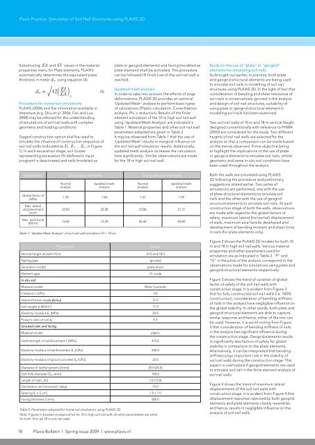
<strong>Plaxis</strong> Practice: <strong>Simulation</strong> <strong>of</strong> Soil <strong>Nail</strong> <strong>Structures</strong> using PLAXIS 2DSubstituting, EA and EI values in the materialproperties menu for Plate elements, PLAXISautomatically determines the equivalent platethickness in meter d eq using equation (4).deq= 12c EAEI mProcedure for numerical simulationsPLAXIS (2006) and the information available inleterature (e.g. Shiu et al. 2006; Fan and Luo2008) may be referred for the understanding<strong>of</strong> simulations <strong>of</strong> soil nail walls with complexgeometry and loading conditions.Staged construction option shall be used tosimulate the infuence <strong>of</strong> construction sequence <strong>of</strong>soil nail walls (indicated as E 1, E 2, …E n, in Figure1). In each excavation stage, soil clusterrepresenting excavation lift (defined in inputprogram) is deactivated and nails (modeled asp(4)plate or geogrid elements) and facing (modeled asplate element) shall be activated. This procedurecan be followed till finish livel <strong>of</strong> the soil nail wall isreached.Updated mesh analysisIn order to take into account the effects <strong>of</strong> largedeformations, PLAXIS 2D provides an optional‘Updated Mesh’ analysis to perform basic types<strong>of</strong> calculations (Plastic calculation, Consolidationanalysis, Phi-c reduction). Results <strong>of</strong> the finiteelement simulation <strong>of</strong> the 10 m high soil nail wallusing ‘Updated Mesh Analysis’ are indicated inTable 1. Material properties and other soil nail wallparameters adopted are given in Table 2.It may be observed from Table 1 that the use <strong>of</strong>‘Updated Mesh’ results in marginal influence onthe soil nail wall simulation results. Additionally,updated mesh analysis increases the calculationtime significantly. Similar observations are madefor the 18 m high soil nail wall.Study on the use <strong>of</strong> “plate” or “geogrid”elements for simulating soil nailsAs brought out earlier, in practice, both plateand geogrid structural elements are being usedto simulate soil nails in modelling <strong>of</strong> soil nailstructures using PLAXIS 2D. In the light <strong>of</strong> fact thatconsideration <strong>of</strong> bending and shear resistance <strong>of</strong>soil nails is conservatively ignored in the analysisand design <strong>of</strong> soil nail structures, suitability <strong>of</strong>using plate or geogrid structural element inmodelling soil nails has been examined.Two soil nail walls <strong>of</strong> 10 m and 18 m vertical heightdesigned conventionally with reference to FHWA(2003) are considered for the study. Two differentheights <strong>of</strong> soil nail walls are selected for theanalysis so that a comparison can be made basedon the trends observed. Prime objective beingto highlight the implications <strong>of</strong> the use <strong>of</strong> plateor geogrid elements to simulate soil nails, similargeometry and same in-situ soil conditions havebeen used throughout the analysis.Parameters Using plate elements Using geogrid elementsGlobal factor <strong>of</strong>safetyMax. lateraldiscplacement(mm)Max. axial force(kN/m)NormalanalysisUpdated meshanalysisNormalanalysisUpdated meshanalysis1.59 1.60 1.57 1.5922.82 22.28 23.86 21.3174.82 73.29 85.44 83.80Table 1: ‘Update Mesh Analysis’ <strong>of</strong> soil nail wall simulation (H = 10 m)ParameterValueVertical height <strong>of</strong> walls H [m] 10.0 and 18.0<strong>Nail</strong>ing type<strong>Simulation</strong> modelElement typegroutedplane strain15- nodeIn-situ soilMaterial modelMohr-CoulombCohesion c [kPa] 4.0Internal friction angle z[deg] 31.5Unit weight c [kN/m 3 ] 17.0Elasticity modulus E s [MPa] 20.0Poison’s ratio <strong>of</strong> soil y s 0.3Grouted nails and facingMaterial modelelasticYield strength <strong>of</strong> reinforcement f y [MPa] 415.0Elasticity modulus <strong>of</strong> reinforcement E n [GPa] 200.0Elasticity modulus <strong>of</strong> grout (concrete) E g [GPa] 22.0Diameter <strong>of</strong> reinforcement d [mm] 20.0 (25.0)Drill hole diameter D DH [mm] 100.0Length <strong>of</strong> nail L [m] 7.0 (13.0)Declination wrt horizontal i [deg] 15.0Spacing S h x S v [m] 1.0 x 1.0Facing thickness t [mm] 200.0Table 2: Parameters adopted for numerical simulations using PLAXIS 2DNote: Figures in bracket correspond tot he 18 m high soil nail wall; all other parameteres are samefor both 10 m ad 18 m soil nail walls.Both the walls are simulated using PLAXIS2D following the procedure and preliminarysuggestions stated earlier. Two series <strong>of</strong>simulations are performed, one with the use<strong>of</strong> plate structural elements to simulate soilnails and the other with the use <strong>of</strong> geogridstructural elements to simulate soil nails. At eachconstruction stage <strong>of</strong> both the walls, observationsare made with regard to the global factors <strong>of</strong>safety, maximum lateral (horizontal) displacement<strong>of</strong> walls, maximum axial tensile developed anddevelopment <strong>of</strong> bending moment and shear forcein nails (for plate elements only).Figure 2 shows the PLAXIS 2D models for both 10m and 18 m high soil nail walls. Various materialproperties and other parameters used forsimulation are as indicated in Table 2. “P” and“G” in the plots <strong>of</strong> the analysis correspond to theobservations made for simulations using plate andgeogrid structural elements respectively.Figure 3 shows the trend <strong>of</strong> variation <strong>of</strong> globalfactor <strong>of</strong> safety <strong>of</strong> the soil nail walls withconstruction stage. It is evident from Figure 3that for fully constructed soil nail walls (i.e. 100%construction), consideration <strong>of</strong> bending stiffness<strong>of</strong> nails in the analysis have negligible influence onthe global stability. In other words, both plate andgeogrid structural elements are able to capturesimilar response and hence, either <strong>of</strong> the two canbe used. However, it is worth noting from Figure3 that consideration <strong>of</strong> bending stiffness <strong>of</strong> nailsin the analysis has significant influence duringthe construction stage. Geogrid elements resultsin significantly less factors <strong>of</strong> safety for globalstability in comparison to the plate elements.Alternatively, it can be interpreted that bendingstiffness plays important role in the stability <strong>of</strong>soil nail walls during the construction stage. Thisaspect is overlooked if geogrid elements are usedto simulate soil nail in the finite element analysis <strong>of</strong>soil nail walls.Figure 4 shows the trend <strong>of</strong> maximum lateraldisplacements <strong>of</strong> the soil nail walls withconstruction stage. It is evident from Figure 4 thatdisplacement response captured by both geogridelements and plate elements closely resemblesand hence, results in negligible influence on theanalysis <strong>of</strong> soil nail walls.18 <strong>Plaxis</strong> Bulletin l Spring issue 2009 l www.plaxis.nl


