Performance and control of the MMT thermal system
Performance and control of the MMT thermal system
Performance and control of the MMT thermal system
You also want an ePaper? Increase the reach of your titles
YUMPU automatically turns print PDFs into web optimized ePapers that Google loves.
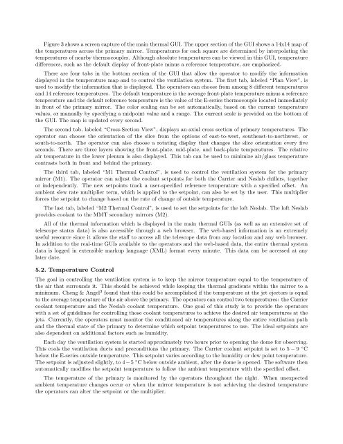
Figure 3 shows a screen capture <strong>of</strong> <strong>the</strong> main <strong>the</strong>rmal GUI. The upper section <strong>of</strong> <strong>the</strong> GUI shows a 14x14 map <strong>of</strong><strong>the</strong> temperatures across <strong>the</strong> primary mirror. Temperatures for each square are determined by interpolating <strong>the</strong>temperatures <strong>of</strong> nearby <strong>the</strong>rmocouples. Although absolute temperatures can be viewed in this GUI, temperaturedifferences, such as <strong>the</strong> default display <strong>of</strong> front-plate minus a reference temperature, are emphasized.There are four tabs in <strong>the</strong> bottom section <strong>of</strong> <strong>the</strong> GUI that allow <strong>the</strong> operator to modify <strong>the</strong> informationdisplayed in <strong>the</strong> temperature map <strong>and</strong> to <strong>control</strong> <strong>the</strong> ventilation <strong>system</strong>. The first tab, labeled “Plan View”, isused to modify <strong>the</strong> information that is displayed. The operators can choose from among 8 different temperatures<strong>and</strong> 14 reference temperatures. The default temperature is <strong>the</strong> average front-plate temperature minus a referencetemperature <strong>and</strong> <strong>the</strong> default reference temperature is <strong>the</strong> value <strong>of</strong> <strong>the</strong> E-series <strong>the</strong>rmocouple located immediatelyin front <strong>of</strong> <strong>the</strong> primary mirror. The color scaling can be set automatically, based on <strong>the</strong> current temperaturevalues, or manually by specifying a midpoint value <strong>and</strong> a range. The current scale is provided on <strong>the</strong> bottom <strong>of</strong><strong>the</strong> GUI. The map is updated every second.The second tab, labeled “Cross-Section View”, displays an axial cross section <strong>of</strong> primary temperatures. Theoperator can choose <strong>the</strong> orientation <strong>of</strong> <strong>the</strong> slice from <strong>the</strong> options <strong>of</strong> east-to-west, sou<strong>the</strong>ast-to-northwest, orsouth-to-north. The operator can also choose a rotating display that changes <strong>the</strong> slice orientation every fiveseconds. There are three layers showing <strong>the</strong> front-plate, mid-plate, <strong>and</strong> back-plate temperatures. The relativeair temperature in <strong>the</strong> lower plenum is also displayed. This tab can be used to minimize air/glass temperaturecontrasts both in front <strong>and</strong> behind <strong>the</strong> primary.The third tab, labeled “M1 Thermal Control”, is used to <strong>control</strong> <strong>the</strong> ventilation <strong>system</strong> for <strong>the</strong> primarymirror (M1). The operator can adjust <strong>the</strong> coolant setpoints for both <strong>the</strong> Carrier <strong>and</strong> Neslab chillers, toge<strong>the</strong>ror independently. The new setpoints track a user-specified reference temperature with a specified <strong>of</strong>fset. Anambient slew rate multiplier term, which is applied to <strong>the</strong> setpoint, can also be set by <strong>the</strong> user. This multiplierforces <strong>the</strong> setpoint to change based on <strong>the</strong> rate <strong>of</strong> change <strong>of</strong> outside temperature.The last tab, labeled “M2 Thermal Control”, is used to set <strong>the</strong> setpoints for <strong>the</strong> l<strong>of</strong>t Neslab. The l<strong>of</strong>t Neslabprovides coolant to <strong>the</strong> <strong>MMT</strong> secondary mirrors (M2).All <strong>of</strong> <strong>the</strong> <strong>the</strong>rmal information which is displayed in <strong>the</strong> main <strong>the</strong>rmal GUIs (as well as an extensive set <strong>of</strong>telescope status data) is also accessible through a web browser. The web-based information is an extremelyuseful resource since it allows <strong>the</strong> staff to access all <strong>the</strong> telescope data from any location <strong>and</strong> any web browser.In addition to <strong>the</strong> real-time GUIs available to <strong>the</strong> operators <strong>and</strong> <strong>the</strong> web-based data, <strong>the</strong> entire <strong>the</strong>rmal <strong>system</strong>data is logged in extensible markup language (XML) format every minute. This data can be accessed at anylater date.5.2. Temperature ControlThe goal in <strong>control</strong>ling <strong>the</strong> ventilation <strong>system</strong> is to keep <strong>the</strong> mirror temperature equal to <strong>the</strong> temperature <strong>of</strong><strong>the</strong> air that surrounds it. This should be achieved while keeping <strong>the</strong> <strong>the</strong>rmal gradients within <strong>the</strong> mirror to aminimum. Cheng & Angel 3 found that this could be accomplished if <strong>the</strong> temperature at <strong>the</strong> jet ejectors is equalto <strong>the</strong> average temperature <strong>of</strong> <strong>the</strong> air above <strong>the</strong> primary. The operators can <strong>control</strong> two temperatures: <strong>the</strong> Carriercoolant temperature <strong>and</strong> <strong>the</strong> Neslab coolant temperature. One goal <strong>of</strong> this study is to provide <strong>the</strong> operatorswith a set <strong>of</strong> guidelines for <strong>control</strong>ling those coolant temperatures to achieve <strong>the</strong> desired air temperatures at <strong>the</strong>jets. Currently, <strong>the</strong> operators must monitor <strong>the</strong> conditioned air temperatures along <strong>the</strong> entire ventilation path<strong>and</strong> <strong>the</strong> <strong>the</strong>rmal state <strong>of</strong> <strong>the</strong> primary to determine which setpoint temperatures to use. The ideal setpoints arealso dependent on additional factors such as humidity.Each day <strong>the</strong> ventilation <strong>system</strong> is started approximately two hours prior to opening <strong>the</strong> dome for observing.This cools <strong>the</strong> ventilation ducts <strong>and</strong> preconditions <strong>the</strong> primary. The Carrier coolant setpoint is set to 5 − 9 ◦ Cbelow <strong>the</strong> E-series outside temperature. This setpoint varies according to <strong>the</strong> humidity or dew point temperature.The setpoint is adjusted slightly, to 4−5 ◦ C below outside ambient, after <strong>the</strong> dome is opened. The s<strong>of</strong>tware <strong>the</strong>nautomatically modifies <strong>the</strong> setpoint temperature to follow <strong>the</strong> ambient temperature with <strong>the</strong> specified <strong>of</strong>fset.The temperature <strong>of</strong> <strong>the</strong> primary is monitored by <strong>the</strong> operators throughout <strong>the</strong> night. When unexpectedambient temperature changes occur or when <strong>the</strong> mirror temperature is not achieving <strong>the</strong> desired temperature<strong>the</strong> operators can alter <strong>the</strong> setpoint or <strong>the</strong> multiplier.


