General Purpose Fuses IEC - Efo-power.ru
General Purpose Fuses IEC - Efo-power.ru
General Purpose Fuses IEC - Efo-power.ru

You also want an ePaper? Increase the reach of your titles
YUMPU automatically turns print PDFs into web optimized ePapers that Google loves.
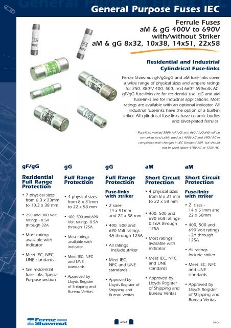
<strong>General</strong> <strong>Purpose</strong> <strong>Fuses</strong> <strong>IEC</strong><strong>General</strong> <strong>Purpose</strong> <strong>Fuses</strong> <strong>IEC</strong>Fer<strong>ru</strong>le <strong>Fuses</strong>aM & gG 400V to 690Vwith/without StrikeraM & gG 8x32, 10x38, 14x51, 22x58Residential and IndustrialCylindrical Fuse-linksFerraz Shawmut gF/gG-gG and aM fuse-links covera wide range of physical sizes and ampere ratingsfor 250, 380*/ 400, 500, and 660* 690volts AC.gF/gG fuse-links are for residential use. gG and aMfuse-links are for industrial applications. Mostratings are available with an optional indicator. Allindustrial fuse-links have the option of a built-instriker. All cylindrical fuse-links have ceramic bodiesand silver-plated fer<strong>ru</strong>les.* Fuse-links marked 380V (gF/gG) and 660V (gG-aM) will bere-marked (and safely used at ) 400V AC and 690V AC incompliance with changes in <strong>IEC</strong> Standard 269, but shouldnot be used above 418V AC or 726V AC.gF/gGgGgGaMaMResidentialFull RangeProtection• 7 physical sizesfrom 6.3 x 23mmto 10.3 x 38 mm• 250 and 380 Voltratings - 0.5Athrough 32A• Most ratingsavailable withindicator• Meet <strong>IEC</strong>, NFC,UNE standards• See residentialfuse-links, Special<strong>Purpose</strong> sectionFull RangeProtection• 4 physical sizesfrom 8 x 31mmto 22 x 58 mm• 400, 500 and 690Volt ratings -0.5Athrough 125A• Most ratingsavailable withindicator• Meet <strong>IEC</strong>, NFCand UNEstandards• Approved byLloyds Registerof Shipping andBureau VeritasFull RangeProtectionFuse-linkswith striker• 2 sizes-14 x 51mmand 22 x 58 mm• 400, 500 and690 Volt ratings4A through 125A• All ratingsinclude striker• Meet <strong>IEC</strong>,NFC and UNEstandards• Approved byLloyds Register ofShipping andBureau VeritasShort CircuitProtection• 4 physical sizesfrom 8 x 31 mmto 22 x 58 mm• 400, 500 and690 Volt ratings-0.16A through125A• Most ratingsavailable withindicator• Meet <strong>IEC</strong>, NFCand UNEstandards• Approved byLloyds Registerof Shipping andBureau VeritasShort CircuitProtectionFuse-linkswith striker• 2 sizes -14 x 51mm and22 x 58mm• 400, 500 and690 Volt ratings- 2A through125A• All ratingsinclude striker• Meet <strong>IEC</strong>, NFCand UNEstandards• Approved byLloyds Registerof Shipping andBureau VeritasGPEU203/06
<strong>General</strong> <strong>Purpose</strong> <strong>Fuses</strong> <strong>IEC</strong><strong>General</strong> <strong>Purpose</strong> <strong>Fuses</strong> <strong>IEC</strong>Fer<strong>ru</strong>le <strong>Fuses</strong>gG 400V to 690Vwith/without StrikergG 8x32, 10x38, 14x51, 22x58X211551M218718K211563Ratings - gG (Optional Blown-Fuse Indicator)Size Rated In Rated Previous References Reference Number Breaking Catalog NumberCurrent (A) Voltage w/o w w/o w Capacity w/o wIndicator Indicator Indicator Indicator Indicator Indicator0.5 15009 - P218191 -FR8GG40V0.51 15011 - C218709FR8GG40V12 15013 15213 Q219227 B222204FR8GG40V24 15019 15219 W222958 X222959FR8GG40V46 15023 15223 A211025 V201291FR8GG40V68 x 31 8 400V 15027 15227 B213096 B211026 20kA - 400V FR8GG40V810 15031 15231 A214613 A212060FR8GG40V1012 15033 15233 R216146 C213097FR8GG40V1216 15035 15235 P216650 Y214105FR8GG40V1620 15037 15237 F217677 J215127FR8GG40V2025 15039 15239 D218710 S216147FR8GG40V250.5 16009 - C211027 -FR10GG50V0.51 16011 - B212061 -FR10GG50V12 16013 16213 D213098 S216653FR10GG50V24 16019 16219 X213598 E217170FR10GG50V46 16023 16223 K215128 T218195FR10GG50V610 X 38 8 500V 16027 16227 D217169 V219231 120kA - 500V10 16031 16231 S218194 E22220712 16033 16233 W219761 H20075116 16035 16235 G200750 H20180920 16037 16237 D211028 X21155125 16039 16239 E213099 W21258532 400V 16043 16243 A214107 Z213600 120kA - 400V1 17011 - K218716 -2 17013 17213 Y219234 C2012984 17019 17219 A219765 H2110326 17023 17223 H222210 G2120668 17027 17227 D222965 K21310410 17031 17231 L200754 H21462014 X 51 12 690V 17033 17233 L201812 R215640 80kA - 690V16 17035 17235 A211554 X21665720 17037 17237 Z212588 N21768425 17039 17239 C213603 M21871832 500V17043 17243 W216656 C219767 120kA - 500V4017047 17247 X218198 F22296750 400V 17051 17251 Z219235 D201299 120kA - 400V2 18013 - F219241 -4 18019 18219 H219772 Q2110396 18023 18223 P222216 P2120738 18027 18227 L222972 R21311010 18031 18231 T200761 N21411912 18033 18233 J201304 Y21514016 18035 18235 S201818 D21615720 18037 18237 P211038 R21718122 x 58 25 690V 18039 18239 N212072 F218206 80kA - 690V32 18043 18243 F212594 H21924340 18047 18247 J213609 R22221850 18051 18251 P214626 W20076363 18055 18255 Y215646 V20182080 18059 18259 Q217180 K211563100 500V 18063 18263 E218205 H212596 120kA -500V125 400V 18065 18265 J219773 L213611 120kA -400VPackaging 10Blown-Fuse IndicatorDimensionsFR10GG50V10FR10GG50V10FR10GG50V12FR10GG50V16FR10GG50V20FR10GG50V25FR10GG40V32FR14GG69V1FR14GG69V2FR14GG69V4FR14GG69V6FR14GG69V8FR14GG69V10FR14GG69V12FR14GG69V16FR14GG69V20FR14GG69V25FR14GG50V32FR14GG50V40FR14GG40V50FR22GG69V2FR22GG69V4FR22GG69V6FR22GG69V8FR22GG69V10FR22GG69V12FR22GG69V16FR22GG69V20FR22GG69V25FR22GG69V32FR22GG69V40FR22GG69V50FR22GG69V63FR22GG69V80FR22GG50V100FR8GG40V2IFR8GG40V4IFR8GG40V6IFR8GG40V8IFR8GG40V10IFR8GG40V12IFR8GG40V16IFR8GG40V20IFR8GG40V25IFR10GG50V2IFR10GG50V4IFR10GG50V6IFR10GG50V10IFR10GG50V10IFR10GG50V12IFR10GG50V16IFR10GG50V20IFR10GG50V25IFR10GG50V32IFR10GG50V2IFR10GG40V32IFR14GG69V2IFR14GG69V4IFR14GG69V6IFR14GG69V8IFR14GG69V10IFR14GG69V12IFR14GG69V16IFR14GG69V20IFR14GG69V25IFR14GG50V32IFR14GG50V40IFR14GG40V50IFR22GG69V4IFR22GG69V6IFR22GG69V8IFR22GG69V10IFR22GG69V12IFR22GG69V16IFR22GG69V20IFR22GG69V25IFR22GG69V32IFR22GG69V40IFR22GG69V50IFR22GG69V63IFR22GG69V80IFR22GG50V100IFR22GG40V125 FR22GG40V125IBEFOREAFTERFuse Size A B C8 x 31 8.5 31.5 6.310 x 38 10.3 38 10.514 x 51 14.3 51 13.822 x 58 22.2 58 16.203/06GPEU3
<strong>General</strong> <strong>Purpose</strong> <strong>Fuses</strong> <strong>IEC</strong><strong>General</strong> <strong>Purpose</strong> <strong>Fuses</strong> <strong>IEC</strong>Fer<strong>ru</strong>le <strong>Fuses</strong>gG 400V to 690Vwith/without StrikergG 8x32, 10x38, 14x51, 22x58Ratings – gI-gG with StrikerP201815R212075Size Rated Rated Previous Reference Breaking Catalog(mm x mm) Current In Voltage Reference Number Capacity Number(A)2 17413 J2110334 17419 H2120676 17423 G2141138 17427 R21513410 17431 Z21615312 17433 L21717614 X 51 16 500V 17435 Z218200 120kA - 500V20 17437 B21923725 17439 L22221332 17443 P20075740 17447 P20181550 400V 17451 D211557 120kA - 400V4 18419 R2146286 18423 A2156488 18427 F21666510 18431 W21769112 18433 W21872616 18435 L21977522 X 58 20 690V 18437 P222975 80kA - 690V25 18439 M20130732 18443 S21104140 18447 R21207550 18451 M21361263 18455 S21462980 18459 F216159100 500V 18463 T217183 120kA - 500V125 400V 18465 H218208 120kA - 400VPackaging 10FR14GG50V2PFR14GG50V4PFR14GG50V6PFR14GG50V8PFR14GG50V10PFR14GG50V12PFR14GG50V16PFR14GG50V20PFR14GG50V25PFR14GG50V32PFR14GG50V40PFR14GG40V50PFR22GG69V4PFR22GG69V6PFR22GG69V8PFR22GG69V10PFR22GG69V12PFR22GG69V16PFR22GG69V20PFR22GG69V25PFR22GG69V32PFR22GG69V40PFR22GG69V50PFR22GG69V63PFR22GG69V80PFR22GG69V100PFR22GG69V125PDimensionsFuse Size A B C D E14 x 51 14.3 51 13.8 7.5 3.822 x 58 22.2 58 16.2 7.5 3.8Striker1 Ceramic body2 Sand3 Indicator contact4 Lower contact5 Contact ring6 Melting element7 IndicatorBEFOREAFTERNeutralSize Previous Reference Standard Catalog(mm x mm) Reference Number Pack/CTN Number10 x 38 19100 R21156914 x 51 19200 M212600 1022 x 58 19300 R213616FRN1038FRN1451FRN2258GPEU4 03/06
<strong>General</strong> <strong>Purpose</strong> <strong>Fuses</strong> <strong>IEC</strong><strong>General</strong> <strong>Purpose</strong> <strong>Fuses</strong> <strong>IEC</strong>Fer<strong>ru</strong>le <strong>Fuses</strong>gG 400V to 690Vwith/without StrikergG 8x32, 10x38, 14x51, 22x58Characteristics t-lPREARCING TIME T(S)PROSPECTIVE CURRENT (A rms)Cut-off characteristicsMAXIMUM VALUE OF CURRENT (KA PEAK)PROSPECTIVE CURRENT (kA rms)03/06GPEU5
<strong>General</strong> <strong>Purpose</strong> <strong>Fuses</strong> <strong>IEC</strong><strong>General</strong> <strong>Purpose</strong> <strong>Fuses</strong> <strong>IEC</strong>Fer<strong>ru</strong>le <strong>Fuses</strong>gG 400V to 690Vwith/without StrikergG 8x32, 10x38, 14x51, 22x58Characteristics I2t2865432gG865432865432865432V}690 V500 V400{- OPERATING I2T- PREARCING I2T865432Table temperature increase (testing in superior contact)ºC1009080706050403020102 4 6 8 10 12 16 20 25 32 2 4 6 8 10 12 16 20 25 32 40 50 16 20 25 32 40 50 63 80 100 125 In10 x 38 14 x 51 22 x 58GPEU6 03/06
<strong>General</strong> <strong>Purpose</strong> <strong>Fuses</strong> <strong>IEC</strong><strong>General</strong> <strong>Purpose</strong> <strong>Fuses</strong> <strong>IEC</strong>Fer<strong>ru</strong>le <strong>Fuses</strong>gG 400V to 690Vwith/without StrikergG 8x32, 10x38, 14x51, 22x58Power loss tableInSize10 x 38 14 x 51 22 x 580,5 A2 W1 A2,5 W3,4 W2 A0,70 W1 W1,20 W4 A0,80 W1,10 W1,30 W6 A0,90 W1,20 W1,40 W8 A1,10 W1,50 W1,65 W10 A1,35 W1,80 W2 W12 A1,55 W2,10 W2,40 W16 A1,90 W2,55 W3 W20 A2,30 W3 W3,40 W25 A2,80 W3,50 W3,80 W32 A3 W3,80 W4,30 W40 A4,40 W5,10 W50 A4,7 W5,50 W63 A6,70 W80 A8 W100 A9 W125 A12,5 WMaximum standardized<strong>power</strong> low.<strong>IEC</strong> 269-2-1NFC 63.213UNE 21.103-2-110 x 3825 A3 W14 x 5140 A5 W22 x 58100 A9,5 WTable of maximum length of network in function of In and conductor section.Maximum standardized <strong>power</strong> low.gG Class <strong>Fuses</strong>Copper conductorsection (mm 2 )Rated Current (In) OF gG <strong>Fuses</strong> (in A)1,52,54610162535501699/1132086/871342540/59110/1221833221/2967/841392144013/1641/51108/119165275507/925/3367/841392266313/2046/5894/113172283808/1124/3255/7013021733610014/1733/4190/1081682573671257,3/1020/2757/70128197283379* 99/118:- 99; Cond. PVC / 118; Cond. PRC03/06GPEU7
<strong>General</strong> <strong>Purpose</strong> <strong>Fuses</strong> <strong>IEC</strong><strong>General</strong> <strong>Purpose</strong> <strong>Fuses</strong> <strong>IEC</strong>Fer<strong>ru</strong>le <strong>Fuses</strong>aM & gG 400V to 690Vwith/without StrikeraM & gG 8x32, 10x38, 14x51, 22x58Residential and IndustrialCylindrical Fuse-linksFerraz Shawmut gF/gG-gG and aM fuse-links covera wide range of physical sizes and ampere ratingsfor 250, 380*/ 400, 500, and 660* 690volts AC.gF/gG fuse-links are for residential use. gG and aMfuse-links are for industrial applications. Mostratings are available with an optional indicator. Allindustrial fuse-links have the option of a built-instriker. All cylindrical fuse-links have ceramic bodiesand silver-plated fer<strong>ru</strong>les.* Fuse-links marked 380V (gF/gG) and 660V (gG-aM) will bere-marked (and safely used at ) 400V AC and 690V AC incompliance with changes in <strong>IEC</strong> Standard 269, but shouldnot be used above 418V AC or 726V AC.gF/gGgGgGaMaMResidentialFull RangeProtection• 7 physical sizesfrom 6.3 x 23mmto 10.3 x 38 mm• 250 and 380 Voltratings - 0.5Athrough 32A• Most ratingsavailable withindicator• Meet <strong>IEC</strong>, NFC,UNE standards• See residentialfuse-links, Special<strong>Purpose</strong> sectionFull RangeProtection• 4 physical sizesfrom 8 x 31mmto 22 x 58 mm• 400, 500 and 690Volt ratings -0.5Athrough 125A• Most ratingsavailable withindicator• Meet <strong>IEC</strong>, NFCand UNEstandards• Approved byLloyds Registerof Shipping andBureau VeritasFull RangeProtectionFuse-linkswith striker• 2 sizes-14 x 51mmand 22 x 58 mm• 400, 500 and690 Volt ratings4A through 125A• All ratingsinclude striker• Meet <strong>IEC</strong>,NFC and UNEstandards• Approved byLloyds Register ofShipping andBureau VeritasShort CircuitProtection• 4 physical sizesfrom 8 x 31 mmto 22 x 58 mm• 400, 500 and690 Volt ratings-0.16A through125A• Most ratingsavailable withindicator• Meet <strong>IEC</strong>, NFCand UNEstandards• Approved byLloyds Registerof Shipping andBureau VeritasShort CircuitProtectionFuse-linkswith striker• 2 sizes -14 x 51mm and22 x 58mm• 400, 500 and690 Volt ratings- 2A through125A• All ratingsinclude striker• Meet <strong>IEC</strong>, NFCand UNEstandards• Approved byLloyds Registerof Shipping andBureau VeritasGPEU2
<strong>General</strong> <strong>Purpose</strong> <strong>Fuses</strong> <strong>IEC</strong><strong>General</strong> <strong>Purpose</strong> <strong>Fuses</strong> <strong>IEC</strong>Fer<strong>ru</strong>le <strong>Fuses</strong>aM 400V to 690Vwith/without StrikeraM 8x32, 10x38, 14x51, 22x58S219229F214618Q217686C215650Blown-Fuse IndicatorRatings – aM (Optional Blown-Fuse Indicator)Size Rated In Rated Previous Reference Reference Number Breaking Catalog Number(mm x mm) Current (A) Voltage w/o w w/o w Capacity w/o w1Indicator Indicator Indicator Indicator Indicator Indicator15511 - C217168 -FR8AM40V12 15513 - R218193 -FR8AM40V24 15519 - S219229 -FR8AM40V48 x 31 6 400V 15523 - C222205 - 20kA - 400V FR8AM40V68 15527 - F200749 -FR8AM40V810 15531 - W201292 -FR8AM40V100.16 16503 - E214617 -FR10AM50V0.160.25 16507 - M215130 -FR10AM50V0.250.5 16509 - W216150 -FR10AM50V0.51 16511 16711 F217171 X219233FR10AM50V1 FR10AM50V1I2 16513 16713 H218714 G222209FR10AM50V2 FR10AM50V2I4 16519 16719 W219232 K200753FR10AM50V4 FR10AM50V4I6 16523 16723 F222208 K201811FR10AM50V6 FR10AM50V6I10 X 38 8 500V 16527 16727 Z201295 Z211553 120kA - 500V FR10AM50V10 FR10AM50V10I10 16531 16731 Y211552 H213102FR10AM50V10 FR10AM50V10I12 16533 16733 A213601 D214110FR10AM50V12 FR10AM50V12I16 16535 16735 F214618 P215132FR10AM50V16 FR10AM50V16I20 16537 16737 X216151 V216655FR10AM50V20 FR10AM50V20I25 400V 16539 16739 G217172 L217682 120kA - 400V FR10AM50V25 FR10AM50V25I32 400V 16543 - J218715 - 120kA - 400V FR10AM50V320.25 17507 - B212590 -FR14AM69V0.250.5 17509 - L213105 -FR14AM69V0.51 17511 17711 E213605 C212591FR14AM69V1 FR14AM69V1I2 17513 17713 H214114 M213106FR14AM69V2 FR14AM69V2I4 17519 17719 K214622 J214115FR14AM69V4 FR14AM69V4I6 17523 17723 S215135 T215136FR14AM69V6 FR14AM69V6I8 17527 17727 T215642 A216660FR14AM69V8 FR14AM69V8I10 17531 17731 Z216659 R217687FR14AM69V10 FR14AM69V10I14 X 51 12 690V 17533 17733 M217177 Q218721 80kA - 690V FR14AM69V12 FR14AM69V12I16 17535 17735 Q217686 F219770FR14AM69V16 FR14AM69V16I20 17537 17737 P218720 R200759FR14AM69V20 FR14AM69V20I25 17539 17739 E219769 Q201816FR14AM69V25 FR14AM69V25I32 17543 17743 M222214 F211559 120kA - 500V FR14AM69V32 FR14AM69V32I40 500V 17547 17747 Q200758 D212592FR14AM69V40 FR14AM69V40I45 17549 17749 L211035 G213607FR14AM69V45 FR14AM69V45I50 400V 17551 17751 E211558 M214624 120kA - 400V FR14AM69V50 FR14AM69V50I1 18511 - M219776 -FR22AM69V12 18513 - T222220 -FR22AM69V24 18519 18719 Q222976 L219246FR22AM69V4 FR22AM69V4I6 18523 18723 Y200765 V222221FR22AM69V6 FR22AM69V6I8 18527 18727 N201308 Y201823FR22AM69V8 FR22AM69V8I10 18531 18731 X201822 N211566FR22AM69V10 FR22AM69V10I12 18533 18731 T211042 K212598FR22AM69V12 FR22AM69V12I16 18535 18735 M211565 P213614FR22AM69V16 FR22AM69V16I22 x 58 20 690V 18537 18737 S212076 V214631 80kA - 690V FR22AM69V20 FR22AM69V20I25 18539 18739 J212597 D215651FR22AM69V25 FR22AM69V25I32 18543 18743 V213113 J216668FR22AM69V32 FR22AM69V32I40 18547 18747 N213613 Z217694FR22AM69V40 FR22AM69V40I50 18551 18751 R214122 P219778FR22AM69V50 FR22AM69V50I63 18555 18755 C215650 Z200766FR22AM69V63 FR22AM69V63I80 18559 18759 H216667 P211567FR22AM69V80 FR22AM69V80I100 500V 18563 18763 Y217693 L212599 120kA - 500V FR22AM69V100 FR22AM69V100I125 400V 18565 18765 J218209 W214632 120kA - 400V FR22AM69V125Packaging 10FR22AM69V125IDimensionsBEFOREAFTERFUSE SIZE A B C8 x 31 8.5 31.5 6.310 x 38 10.3 38 10.514 x 51 14.3 51 13.822 x 58 22.2 58 16.2GPEC8
<strong>General</strong> <strong>Purpose</strong> <strong>Fuses</strong> <strong>IEC</strong><strong>General</strong> <strong>Purpose</strong> <strong>Fuses</strong> <strong>IEC</strong>Fer<strong>ru</strong>le <strong>Fuses</strong>aM 400V to 690Vwith/without StrikeraM 8x32, 10x38, 14x51, 22x58Ratings – aM with StrikerX215645K216669Size Rated Rated Previous Reference Breaking Catalog(mm x mm) Current In Voltage Reference Number Capacity Number.(A)1 17911 W2156442 17913 B2166614 17919 C2182036 17923 E2192408 17927 N22221510 17931 S20076014 X 51 12 500V 17933 R201817 120kA 500V16 17935 G21156020 17937 E21259325 17939 H21360832 17943 N21462540 17947 X21564545 17949 C21666250 400V 17951 D218204 120kA - 400V1 18911 E2156522 18913 J2161624 18919 A2176956 18923 Y2187288 18927 Q21977910 18931 S22297812 18933 R20131116 18935 W21104422 X 58 20 690V 18937 W212079 80kA - 690V25 18939 Q21361532 18943 X21463340 18947 F21565350 18951 K21666963 18955 B21769680 500V 18959 Z218729 120kA - 500V100 18963 T222979125 400V 18965 S201312 120kA - 400VPackaging 10FR14AM69V1PFR14AM69V2PFR14AM69V4PFR14AM69V6PFR14AM69V8PFR14AM69V10PFR14AM69V12PFR14AM69V16PFR14AM69V20PFR14AM69V25PFR14AM69V32PFR14AM69V40PFR14AM69V45PFR14AM69V50PFR22AM69V1PFR22AM69V2PFR22AM69V4PFR22AM69V6PFR22AM69V8PFR22AM69V10PFR22AM69V12PFR22AM69V16PFR22AM69V20PFR22AM69V25PFR22AM69V32PFR22AM69V40PFR22AM69V50PFR22AM69V63PFR22AM69V80PFR22AM69V100PFR22AM69V125PDimensionsStrikerFuse Size A B C D E14 x 51 14.3 51 13.8 7.5 3.822 x 58 22.2 58 16.2 7.5 3.8BEFOREAFTERNeutralSize Previous Reference Standard Catalog(mm x mm) Reference Number Pack/CTN Number10 x 38 19100 R21156914 x 51 19200 M212600 1022 x 58 19300 R213616FRN1038FRN1451FRN2258GPEU9
<strong>General</strong> <strong>Purpose</strong> <strong>Fuses</strong> <strong>IEC</strong><strong>General</strong> <strong>Purpose</strong> <strong>Fuses</strong> <strong>IEC</strong>Fer<strong>ru</strong>le <strong>Fuses</strong>aM 400V to 690Vwith/without StrikeraM 8x32, 10x38, 14x51, 22x58Characteristics t-laMPREARCING TIME T(S)PROSPECTIVE CURRENT (A rms)Cut-off characteristicsMAXIMUM VALUE OF CURRENT (KA PEAK)PROSPECTIVE CURRENT (kA rms)GPEU10
<strong>General</strong> <strong>Purpose</strong> <strong>Fuses</strong> <strong>IEC</strong><strong>General</strong> <strong>Purpose</strong> <strong>Fuses</strong> <strong>IEC</strong>Fer<strong>ru</strong>le <strong>Fuses</strong>gG 400V to 690Vwith/without StrikeraM 8x32, 10x38, 14x51, 22x58Characteristics I2tI 2 T VALUE (A 2 S)aMV}690 V500 V400{- OPERATING I2T- PREARCING I2TRATED CURRENT (A)ºCTemperature increase table (testing in superior contact)80706050403020101 2 4 6 8 10 12 16 20 25 32 1 2 4 6 8 10 12 16 20 25 32 40 50 1 2 4 6 8 10 12 16 20 25 32 40 50 63 80 100 125 In10 x 38 14 x 51 22 x 58GPEU11
<strong>General</strong> <strong>Purpose</strong> <strong>Fuses</strong> <strong>IEC</strong><strong>General</strong> <strong>Purpose</strong> <strong>Fuses</strong> <strong>IEC</strong>Fer<strong>ru</strong>le <strong>Fuses</strong>aM 400V to 690Vwith/without StrikeraM 8x32, 10x38, 14x51, 22x58Power loss tableInSize10 x 38 14 x 51 22 x 580,16 A0,25 A0,5 A1 A2 A4 A6 A8 A10 A12 A16 A20 A25 A32 A40 A45 A50 A63 A80 A100 A125 A0,35 W0,50 W0,50 W0,13 W0,20 W0,30 W0,45 W0,55 W0,65 W0,75 W0,90 W1,10 W1,40 W2 W0,70 W0,75 W0,18 W0,25 W0,40 W0,55 W0,65 W0,75 W0,85 W1,20 W1,50 W1,80 W2,10 W2,60 W2,80 W2,90 W0,20 W0,30 W0,50 W0,65 W0,75 W0,85 W1 W1,40 W1,70 W2 W2,60 W3,20 W3,90 W4,60 W5,60 W6,50 W9,50 WMaximum standardized<strong>power</strong> low.<strong>IEC</strong> 269-2-1NFC 63.213UNE 21.103-2-110 x 3816 A1,2 W14 x 5150 A3 W22 x 58100 A7 WTable of maximum length of network in function of In and conductor section.Maximum standardized <strong>power</strong> low.aM Class <strong>Fuses</strong>Copperconductorsection (mm 2 )Rated Current (In) OF aM <strong>Fuses</strong> (in A)1,52,546101625351655/641161812732037/4584/941472232525/3058/681181783215/2040/4984/951392274026/3258/68105/1171815017/2042/4879/891472366328/3355/64113/1251898018/2337/4280/9415123110026/3157/6912018526212514/2040/4783/97147210GPEU12
<strong>General</strong> <strong>Purpose</strong> <strong>IEC</strong> <strong>Fuses</strong><strong>General</strong> <strong>Purpose</strong> <strong>IEC</strong> <strong>Fuses</strong>NH <strong>Fuses</strong> (Plain Blades)gG 400V, 500V, 690VaM 500V, 690VNH Fuse SystemDIN 57 636/VDE 0636 Parts 1, 10, 21, 22, 201<strong>IEC</strong> 60269-2DIN 43 620 Parts 1 to 4 (Standard dimensions)The use category is identified by two letters, the first indicating theoperational class and the second the object to be protected.The Ferraz shawmut range includes fuse-links to DIN VDE 0636standard for the following uses categories:gG: general purpose cable and line protectionaM: Partial purpose, motor circuit protectiongTr: general purpose, transformer protectiongR: general purpose, fast actingaR: partial purpose, fast actingClassificationThe NH system is classed among plug-in fuse systems and is comprised of:- fuse-base, (possibly including terminal covers and phase barriers)- fuse-link with blade contact- fuse-link replacement device (LV HRC fuse puller)Since the design of this system cannot guarantee non-interchangeability of rated current, it must behandled by a qualified professional.Approval symbolsGermanyAustria~0% lead~0% cadmiumSwitzerlandNetherlands~it costs younot a pennymore !~it corresponds with the2nd design of Europeanelectronical scrapsguideline~100% for a sure futureGPEU13
<strong>General</strong> <strong>Purpose</strong> <strong>IEC</strong> <strong>Fuses</strong><strong>General</strong> <strong>Purpose</strong> <strong>IEC</strong> <strong>Fuses</strong>NH <strong>Fuses</strong> (Plain Blades)gG 400V, 500V, 690VgG 400V Size 000 to 3NH-fuses, 400VAC gGPb-freewith non-isolated grippinglugs, double indicator,contact blades, complyingwith DIN VDE 0636Part 201and <strong>IEC</strong> 60269-2-1SizeRated current Power dissipationMicro- weightFS ref.-no. Previous ref.I N (A) (W) switch (1) kg/pcepack.Catalog Number000 2 3,3 Z223674 1A613. Y 0,12 3000 4 1,35 A223675 1A619. Y 0,12 3000 6 1,7 B223676 1A623. Y 0,12 3000 10 1,0 C223677 1A631. Y 0,12 3000 16 1,8 D223678 1A635. Y 0,12 9000 20 2,0 E223679 1A637. Y 0,12 9000 25 2,4 F223680 1A639. Y 0,12 9000 32 2,6 G223681 1A643. Y 0,12 9000 35 3,2 H223682 1A645. Y 0,12 9000 40 3,1 J223683 1A647. Y 0,12 9000 50 3,5 K223684 1A651. Y 0,12 9000 63 4,6 L223685 1A655. Y 0,12 9000 80 5,0 M223686 1A659. Y 0,12 9000 100 5,5 N223687 1A663. Y 0,12 900 125 8,6 E223702 1A765. Y 0,18 300 160 9,6 F223703 1A769. Y 0,18 31 35 3,9 J223706 1A145. N 0,28 31 50 4,5 K223707 1A151. N 0,28 31 63 5,7 L223708 1A155. N 0,28 31 80 5,5 M223709 1A159. N 0,28 31 100 7,0 N223710 1A163. N 0,28 31 125 9,1 P223711 1A165. N 0,30 31 160 13,0 Q223712 1A169. Y 0,30 31 200 13,1 R223713 1A171. Y 0,30 31 224 15,1 S223714 1A173. Y 0,30 31 250 16,9 T223715 1A175. Y 0,30 32 35 3,9 T227257 1A245. N 1,87 32 50 4,5 V227258 1A251. N 1,87 32 63 5,7 W227259 1A255. N 1,87 32 80 6,1 F223726 1A259. N 0,32 32 100 7,3 G223727 1A263. N 0,32 32 125 9,1 H223728 1A265. N 0,32 32 160 13,0 J223729 1A269. N 0,32 32 200 13,5 K223730 1A271. N 0,32 32 224 15,1 L223731 1A273. N 0,32 32 250 18,0 M223732 1A275. N 0,32 32 315 19,9 N223733 1A279. Y 0,40 32 355 22,7 P223734 1A281. Y 0,40 32 400 28,0 Q223735 1A283. Y 0,40 33 250 19,9 R223736 1A375. N 0,45 13 315 22,7 S223737 1A379. N 0,45 13 400 28,0 T223738 1A383. Y 0,45 13 500 30,8 V223739 1A387. Y 0,60 13 630 43,0 W223740 1A389. Y 0,60 1(1) Suitable for Microswitch describes gG/aM Mechanics for Ceramic body Section page GPEU34NH000GG40V2NH000GG40V4NH000GG40V6NH000GG40V10NH000GG40V16NH000GG40V20NH000GG40V25NH000GG40V32NH000GG40V35NH000GG40V45NH000GG40V50NH000GG40V63NH000GG40V80NH000GG40V100NH00GG40V125NH00GG40V160NH1GG40V35NH1GG40V50NH1GG40V63NH1GG40V80NH1GG40V100NH1GG40V125NH1GG40V160NH1GG40V200NH1GG40V224NH1GG40V250NH2GG40V35NH2GG40V50NH2GG40V63NH2GG40V80NH2GG40V100NH2GG40V125NH2GG40V160NH2GG40V200NH2GG40V224NH2GG40V250NH2GG40V315NH2GG40V355NH2GG40V400NH3GG40V250NH3GG40V315NH3GG40V400NH3GG40V500NH3GG40V630GPEU14
<strong>General</strong> <strong>Purpose</strong> <strong>IEC</strong> <strong>Fuses</strong><strong>General</strong> <strong>Purpose</strong> <strong>IEC</strong> <strong>Fuses</strong>NH <strong>Fuses</strong> (Plain Blades)gG 400V, 500V, 690VgG Curves SetNH-fuses, 400VAC, 500VAC gGTotal Clearing I 2 tCurrent Limitation Curves10 710 6 10 4 10 5 10 650000003000000200000010 650000030000020000010 550000300002000010 450003000200010 350030020010 25030201053212 4 6 10 16 20 2532 35 40 50 63 80 100 125 160 200 224 250 300315355 400 425 500 630 800 1000 1250PEAK LET-THRU IN KA10 510 410 310 210 210 3Im = 2.3 IpSHORT CIRCUIT CURRENT I p IN kA1250 A1000 A800 A630 A500 A450 A425 A400 A355 A315 A300 A250 A224 A200 A160 A125 A100 A80 A63 A50 A40 A35 A32 A25 A20 A16 A10 A6 A4 A2 ARated current in ATime VS. Current CharacteristicsRATED CURRENT IN A2 A4 A6 A10 A16 A20 A25 A32 A35 A40 A50 A63 A80 A100 A125 A160 A200 A224 A250 A300 A315 A355 A400 A425 A450 A500 A630 A800 A1000 A1250 A10 4 10 10 3 10 4 10 510 310 2MELTING TIME10110 -110 -21 2 4 6 8PROSPECTIVE CURRENT I P IN A10 2GPEU23
<strong>General</strong> <strong>Purpose</strong> <strong>IEC</strong> <strong>Fuses</strong><strong>General</strong> <strong>Purpose</strong> <strong>IEC</strong> <strong>Fuses</strong>NH <strong>Fuses</strong> (Plain Blades)gG 400V, 500V, 690VNH Fuse SystemDIN 57 636/VDE 0636 Parts 1, 10, 21, 22, 201<strong>IEC</strong> 60269-2DIN 43 620 Parts 1 to 4 (Standard dimensions)The use category is identified by two letters, the first indicating theoperational class and the second the object to be protected.The Ferraz shawmut range includes fuse-links to DIN VDE 0636standard for the following uses categories:gG: general purpose cable and line protectionaM: Partial purpose, motor circuit protectiongTr: general purpose, transformer protectiongR: general purpose, fast actingaR: partial purpose, fast actingClassificationThe NH system is classed among plug-in fuse systems and is comprised of:- fuse-base, (possibly including terminal covers and phase barriers)- fuse-link with blade contact- fuse-link replacement device (LV HRC fuse puller)Since the design of this system cannot guarantee non-interchangeability of rated current, it must behandled by a qualified professional.Approval symbolsGermanyAustria~0% lead~0% cadmiumSwitzerlandNetherlands~it costs younot a eannymore !~it corresponds with the2nd design of Europeanelectronical scrapsguideline~100% for a sure futureGPEU13
<strong>General</strong> <strong>Purpose</strong> <strong>IEC</strong> <strong>Fuses</strong><strong>General</strong> <strong>Purpose</strong> <strong>IEC</strong> <strong>Fuses</strong>NH <strong>Fuses</strong> (Plain Blades)gG 400V, 500V, 690VgG 400V Size 000 to 3 - Isolated LugNH-fuses, 400VAC gGwith isolated metal grippinglugs (SGL),double indicator,contact blades, complyingwithDIN VDE 0636 Part 201and <strong>IEC</strong> 60269-2-1Pb-freeSizeRated current Power dissipationweightFS ref.-no. Previous ref.I N (A) (W) kg/pcepack.Catalog Number000 2 3,3 P223688 1E613. 0,12 3000 4 1,35 Q223689 1E619. 0,12 3000 6 1,7 R223690 1E623. 0,12 3000 10 1,0 S223691 1E631. 0,12 3000 16 1,8 T223692 1E635. 0,12 9000 20 2,0 V223693 1E637. 0,12 9000 25 2,4 W223694 1E639. 0,12 9000 32 2,6 X223695 1E643. 0,12 9000 35 3,2 Y223696 1E645. 0,12 9000 40 3,1 Z223697 1E647. 0,12 9000 50 3,5 A223698 1E651. 0,12 9000 63 4,6 B223699 1E655. 0,12 9000 80 5,0 C223700 1E659. 0,12 9000 100 5,5 D223701 1E663. 0,12 900 125 8,6 G223704 1E765. 0,18 300 160 9,6 H223705 1E769. 0,18 31 35 3,9 V223716 1E145. 0,28 31 50 4,5 W223717 1E151. 0,28 31 63 5,7 X223718 1E155. 0,28 31 80 5,5 Y223719 1E159. 0,28 31 100 7,0 Z223720 1E163. 0,28 31 125 9,1 A223721 1E165. 0,30 31 160 13,0 B223722 1E169. 0,30 31 200 13,1 C223723 1E171. 0,30 31 224 15,1 D223724 1E173. 0,30 31 250 16,9 E223725 1E175. 0,30 32 35 3,9 L227250 1E245. 2,65 32 50 4,5 M227251 1E251. 2,65 32 63 5,7 N227252 1E255. 2,65 32 80 6,1 X223741 1E259. 0,32 32 100 7,3 Y223742 1E263. 0,32 32 125 9,1 Z223743 1E265. 0,32 32 160 13,0 A223744 1E269. 0,32 32 200 13,5 B223745 1E271. 0,32 32 224 15,1 C223746 1E273. 0,32 32 250 18,0 D223747 1E275. 0,32 32 315 19,9 E223748 1E279. 0,40 32 355 22,7 F223749 1E281. 0,40 32 400 28,0 G223750 1E283. 0,40 33 250 19,9 H223751 1E375. 0,45 13 315 22,7 J223752 1E379. 0,45 13 400 28,0 K223753 1E383. 0,45 13 500 30,8 L223754 1E387. 0,60 13 630 43,0 M223755 1E389. 0,60 1Non suitable for Microswitch.NH000GG40V2-1NH000GG40V4-1NH000GG40V6-1NH000GG40V10-1NH000GG40V16-1NH000GG40V20-1NH000GG40V25-1NH000GG40V32-1NH000GG40V35-1NH000GG40V40-1NH000GG40V50-1NH000GG40V63-1NH000GG40V80-1NH000GG40V100-1NH00GG40V125-1NH00GG40V160-1NH1GG40V35-1NH1GG40V50-1NH1GG40V63-1NH1GG40V80-1NH1GG40V100-1NH1GG40V125-1NH1GG40V160-1NH1GG40V200-1NH1GG40V224-1NH1GG40V250-1NH2GG40V35-1NH2GG40V50-1NH2GG40V63-1NH2GG40V80-1NH2GG40V100-1NH2GG40V125-1NH2GG40V160-1NH2GG40V200-1NH2GG40V224-1NH2GG40V250-1NH2GG40V315-1NH2GG40V355-1NH2GG40V400-1NH3GG40V250-1NH3GG40V315-1NH3GG40V400-1NH3GG40V500-1NH3GG40V630-1GPEU15
<strong>General</strong> <strong>Purpose</strong> <strong>IEC</strong> <strong>Fuses</strong><strong>General</strong> <strong>Purpose</strong> <strong>IEC</strong> <strong>Fuses</strong>NH <strong>Fuses</strong> (Plain Blades)gG 400V, 500V, 690VgG Curves SetNH-fuses, 500VAC gGTotal Clearing I 2 tCurrent Limitation Curves10 710 6 10 4 10 5 10 650000003000000200000010 650000030000020000010 550000300002000010 450003000200010 350030020010 25030201053212 4 6 10 16 20 2532 35 40 50 63 80 100 125 160 200 224 250 300315355 400 425 500 630 800 1000 1250PEAK LET-THRU IN KA10 510 410 310 210 210 3Im = 2.3 IpSHORT CIRCUIT CURRENT I p IN kA1250 A1000 A800 A630 A500 A450 A425 A400 A355 A315 A300 A250 A224 A200 A160 A125 A100 A80 A63 A50 A40 A35 A32 A25 A20 A16 A10 A6 A4 A2 ARated current in ATime VS. Current CharacteristicsRATED CURRENT IN A2 A4 A6 A10 A16 A20 A25 A32 A35 A40 A50 A63 A80 A100 A125 A160 A200 A224 A250 A300 A315 A355 A400 A425 A450 A500 A630 A800 A1000 A1250 A10 4 10 10 3 10 4 10 510 310 2MELTING TIME10110 -110 -21 2 4 6 8PROSPECTIVE CURRENT I P IN A10 2GPEU23
<strong>General</strong> <strong>Purpose</strong> <strong>IEC</strong> <strong>Fuses</strong><strong>General</strong> <strong>Purpose</strong> <strong>IEC</strong> <strong>Fuses</strong>NH <strong>Fuses</strong> (Plain Blades)gG 400V, 500V, 690VNH Fuse SystemDIN 57 636/VDE 0636 Parts 1, 10, 21, 22, 201<strong>IEC</strong> 60269-2DIN 43 620 Parts 1 to 4 (Standard dimensions)The use category is identified by two letters, the first indicating theoperational class and the second the object to be protected.The Ferraz shawmut range includes fuse-links to DIN VDE 0636standard for the following uses categories:gG: general purpose cable and line protectionaM: Partial purpose, motor circuit protectiongTr: general purpose, transformer protectiongR: general purpose, fast actingaR: partial purpose, fast actingClassificationThe NH system is classed among plug-in fuse systems and is comprised of:- fuse-base, (possibly including terminal covers and phase barriers)- fuse-link with blade contact- fuse-link replacement device (LV HRC fuse puller)Since the design of this system cannot guarantee non-interchangeability of rated current, it must behandled by a qualified professional.Approval symbolsGermanyAustria~0% lead~0% cadmiumSwitzerlandNetherlands~it costs younot a eannymore !~it corresponds with the2nd design of Europeanelectronical scrapsguideline~100% for a sure futureGPEU13
<strong>General</strong> <strong>Purpose</strong> <strong>IEC</strong> <strong>Fuses</strong><strong>General</strong> <strong>Purpose</strong> <strong>IEC</strong> <strong>Fuses</strong>NH <strong>Fuses</strong> (Plain Blades)gG 400V, 500V, 690VgG 500V Size 000 to 4aNH-fuses, 500VAC gGCd/Pb-freewith non-isolated gripping lugs, double indicator, contact blades, complyingwith DIN VDE 0636 Part 201 and <strong>IEC</strong> 60269-2-1SizeRated current Power dissipationMicro- weightFS ref.-no. Previous ref.I N (A) (W) switch (1) kg/pcepack.Catalog Number000 2 1,9 B211946 1B613. Y 0,13 3000 4 1,5 M212462 1B619. Y 0,13 3000 6 1,6 D213995 1B623. Y 0,13 3000 10 1,1 B219651 1B631. Y 0,13 3000 16 1,8 K222097 1B635. Y 0,13 9000 20 2,3 A222847 1B637. Y 0,13 9000 25 2,4 E201185 1B639. Y 0,13 9000 32 3,1 Z211438 1B643. Y 0,13 9000 35 3,0 C211947 1B645. Y 0,13 9000 40 3,7 N212463 1B647. Y 0,13 9000 50 4,1 T212974 1B651. Y 0,13 9000 63 5,4 E213996 1B655. Y 0,13 9000 80 6,5 Y216543 1B659. Y 0,13 9000 100 7,5 B219122 1B663. Y 0,13 900 125 10,0 R201863 1B765. Y 0,20 300 160 12,3 P211084 1B769. Y 0,20 30 6 1,6 H213148 1B023. Y 0,27 30 10 1,1 G214159 1B031. Y 0,27 30 16 1,8 Q215179 1B035. Y 0,27 30 20 2,3 R215686 1B037. Y 0,27 30 25 2,4 Y216198 1B039. Y 0,27 30 32 3,1 W216702 1B043. Y 0,27 30 35 3,0 J217220 1B045. Y 0,27 30 40 3,7 P217731 1B047. Y 0,27 30 50 4,1 Z218246 1B051. Y 0,27 30 63 6,6 N218765 1B055. Y 0,27 30 80 8,0 C219284 1B059. Y 0,27 30 100 9,4 D219814 1B063. Y 0,27 30 125 11,8 P222492 1B065. Y 0,27 30 160 14,6 F223013 1B069. Y 0,27 30 200 18,1 C229611 1B071. Y 0,27 30 224 19,2 D229612 1B073. Y 0,27 30 250 20,3 E229613 1B075. Y 0,27 31 16 1,8 M200801 1B135. N 0,28 31 20 2,3 C201344 1B137. N 0,28 31 25 2,4 N201860 1B139. N 0,28 31 32 3,1 L211081 1B143. N 0,28 31 35 3,0 A211600 1B145. N 0,28 31 40 3,7 Y212633 1B147. N 0,28 31 50 4,1 B213648 1B151. N 0,28 31 63 6,6 L214669 1B155. N 0,28 31 80 8,0 S215687 1B159. N 0,28 31 100 9,4 X216703 1B163. N 0,28 31 125 11,8 Q217732 1B165. Y 0,30 31 160 14,6 A218247 1B169. Y 0,30 31 200 18,0 P218766 1B171. Y 0,30 31 224 19,0 D219285 1B173. Y 0,30 31 250 20,0 E219815 1B175. Y 0,30 31 315 20,5 Q228519 1B179. Y 0,42 31 355 23,7 R228520 1B181. Y 0,42 3(1) Suitable for Microswitch describes page 106NH000GG50V2NH000GG50V4NH000GG50V6NH000GG50V10NH000GG50V16NH000GG50V20NH000GG50V25NH000GG50V32NH000GG50V35NH000GG50V40NH000GG50V50NH000GG50V63NH000GG50V80NH000GG50V100NH00GG50V125NH00GG50V160NH0GG50V6NH0GG50V10NH0GG50V16NH0GG50V20NH0GG50V25NH0GG50V32NH0GG50V35NH0GG50V40NH0GG50V50NH0GG50V63NH0GG50V80NH0GG50V100NH0GG50V125NH0GG50V160NH0GG50V200NH0GG50V224NH0GG50V250NH1GG50V16NH1GG50V20NH1GG50V25NH1GG50V32NH1GG50V35NH1GG50V40NH1GG50V50NH1GG50V63NH1GG50V80NH1GG50V100NH1GG50V125NH1GG50V160NH1GG50V200NH1GG50V224NH1GG50V250NH1GG50V315NH1GG50V355GPEU16
<strong>General</strong> <strong>Purpose</strong> <strong>IEC</strong> <strong>Fuses</strong><strong>General</strong> <strong>Purpose</strong> <strong>IEC</strong> <strong>Fuses</strong>NH <strong>Fuses</strong> (Plain Blades)gG 400V, 500V, 690VgG 500V Size 000 to 4aNH-fuses, 500VAC gGwith non-isolated gripping lugs, double indicator, contact blades, complyingwith DIN VDE 0636 Part 201 and <strong>IEC</strong> 60269-2-1Cd/Pb-freeSizeRated current Power dissipationMicro- weightFS ref.-no. Previous ref.I N (A) (W) switch (1) kg/pcepack.Catalog Number2 25 2,4 N200802 1B239. N 0,42 32 32 3,1 D201345 1B243. N 0,42 32 35 3,0 P201861 1B245. N 0,42 32 40 3,7 M211082 1B247. N 0,42 32 50 4,1 B211601 1B251. N 0,42 32 63 6,8 Z212634 1B255. N 0,42 32 80 8,3 C213649 1B259. N 0,42 32 100 10,7 M214670 1B263. N 0,42 32 125 12,2 T215688 1B265. N 0,42 32 160 15,0 Y216704 1B269. N 0,42 32 200 18,5 R217733 1B271. N 0,42 32 224 19,2 Q218767 1B273. N 0,42 32 250 20,6 R222494 1B275. N 0,42 32 300 21,0 P200803 1B277. Y 0,64 32 315 25,0 E201346 1B279. Y 0,64 32 355 31,5 Q201862 1B281. Y 0,64 32 400 28,5 N211083 1B283. Y 0,64 32 425 29,2 S228521 1B285. Y 0,64 32 500 35,6 T228522 1B287. Y 0,64 33 250 21,1 C211602 1B375. N 0,65 13 300 20,0 A212635 1B377. N 0,65 13 315 25,0 L213151 1B379. N 0,65 13 355 32,0 K214162 1B381. N 0,65 13 400 34,0 T215182 1B383. N 1,05 13 425 34,0 B216201 1B385. Y 1,05 13 450 38,0 Z216705 1B386. Y 1,05 13 500 43,0 M217223 1B387. Y 1,05 13 630 43,1 S217734 1B389. Y 1,05 13 800 53,2 V228523 1B391. Y 1,05 1with screw contact4 400 31,0 *) A216039 8004.4007 N 2,00 14 500 35,0 *) X216542 8004.5007 N 2,00 14 630 46,6 *) W217576 8004.6307 N 2,00 14 800 70,0 *) E218090 8004.8007 N 2,00 14 1000 83,3 *) H201694 8004.1007 N 2,00 14 1250 110,0 *) C213994 8004.1257 N 2,00 1contact blades for NH-bottom size 4a with swivel unit4a 500 35,0 *) D201184 8014.5007 N 1,95 14a 630 46,6 *) T205752 8014.6307 N 1,95 14a 800 70,0 *) Y211437 8014.8007 N 1,95 14a 1000 83,3 *) A219650 8014.1007 N 1,95 14a 1250 110,0 *) J200637 8014.1257 N 1,95 1*) with indicator on top(1) Suitable for Microswitch describes page 106NH2GG50V25NH2GG50V32NH2GG50V35NH2GG50V40NH2GG50V50NH2GG50V63NH2GG50V80NH2GG50V100NH2GG50V125NH2GG50V160NH2GG50V200NH2GG50V224NH2GG50V250NH2GG50V300NH2GG50V315NH2GG50V355NH2GG50V400NH2GG50V425NH2GG50V500NH3GG50V250NH3GG50V300NH3GG50V315NH3GG50V355NH3GG50V400NH3GG50V425NH3GG50V450NH3GG50V500NH3GG50V630NH3GG50V800NH4GG50V400-8NH4GG50V500-8NH4GG50V630-8NH4GG50V800-8NH4GG50V1000-8NH4GG50V1250-8NH4AGG50V500-8NH4AGG50V630-8NH4AGG50V800-8NH4AGG50V1000-8NH4AGG50V1250-8GPEU17
<strong>General</strong> <strong>Purpose</strong> <strong>IEC</strong> <strong>Fuses</strong><strong>General</strong> <strong>Purpose</strong> <strong>IEC</strong> <strong>Fuses</strong>NH <strong>Fuses</strong> (Plain Blades)gG 400V, 500V, 690VNH Fuse SystemDIN 57 636/VDE 0636 Parts 1, 10, 21, 22, 201<strong>IEC</strong> 60269-2DIN 43 620 Parts 1 to 4 (Standard dimensions)The use category is identified by two letters, the first indicating theoperational class and the second the object to be protected.The Ferraz shawmut range includes fuse-links to DIN VDE 0636standard for the following uses categories:gG: general purpose cable and line protectionaM: Partial purpose, motor circuit protectiongTr: general purpose, transformer protectiongR: general purpose, fast actingaR: partial purpose, fast actingClassificationThe NH system is classed among plug-in fuse systems and is comprised of:- fuse-base, (possibly including terminal covers and phase barriers)- fuse-link with blade contact- fuse-link replacement device (LV HRC fuse puller)Since the design of this system cannot guarantee non-interchangeability of rated current, it must behandled by a qualified professional.Approval symbolsGermanyAustria~0% lead~0% cadmiumSwitzerlandNetherlands~it costs younot a eannymore !~it corresponds with the2nd design of Europeanelectronical scrapsguideline~100% for a sure futureGPEU13
<strong>General</strong> <strong>Purpose</strong> <strong>IEC</strong> <strong>Fuses</strong><strong>General</strong> <strong>Purpose</strong> <strong>IEC</strong> <strong>Fuses</strong>NH <strong>Fuses</strong> (Plain Blades)gG 400V, 500V, 690VgG 500V Size 000 to 3 - Isolated LugNH-fuses, 500VAC gGwith isolated metal grippinglugs (SGL), double indicator,contact blades, complyingwith DIN VDE 0636 Part 201and <strong>IEC</strong> 60269-2-1Cd/Pb-freeSizeRated current Power dissipationweightFS ref.-no. Previous ref.I N (A) (W) kg/pcepack.Catalog Number2 25 2,4 J219819 1F239. 0,42 32 32 3,1 V222497 1F243. 0,42 32 35 3,0 L223018 1F245. 0,42 32 40 3,7 S200806 1F247. 0,42 32 50 4,1 H201349 1F251. 0,42 32 63 6,8 T201865 1F255. 0,42 32 80 8,3 F211605 1F259. 0,42 32 100 10,7 P213154 1F263. 0,42 32 125 12,2 N214165 1F265. 0,42 32 160 15,0 X215185 1F269. 0,42 32 200 18,5 E216204 1F271. 0,42 32 224 19,2 Q217226 1F273. 0,42 32 250 20,6 F218252 1F275. 0,42 32 300 21,0 H219289 1F277. 0,64 32 315 25,0 K219820 1F279. 0,64 32 355 31,5 M223019 1F281. 0,64 32 400 28,5 T200807 1F283. 0,64 33 250 21,1 J201350 1F375. 0,65 13 300 20,0 S211087 1F377. 0,65 13 315 25,0 G211606 1F379. 0,65 13 355 32,0 E212639 1F381. 0,65 13 400 34,0 H213654 1F383. 1,05 13 425 34,0 S214675 1F385. 1,05 13 450 38,0 Z215693 1F386. 1,05 13 500 43,0 F216205 1F387. 1,05 13 630 43,1 D216709 1F389. 1,05 1NH2GG50V25-1NH2GG50V32-1NH2GG50V35-1NH2GG50V40-1NH2GG50V50-1NH2GG50V63-1NH2GG50V80-1NH2GG50V100-1NH2GG50V125-1NH2GG50V160-1NH2GG50V200-1NH2GG50V224-1NH2GG50V250-1NH2GG50V300-1NH2GG50V315-1NH2GG50V355-1NH2GG50V400-1NH3GG50V250-1NH3GG50V300-1NH3GG50V315-1NH3GG50V355-1NH3GG50V400-1NH3GG50V425-1NH3GG50V450-1NH3GG50V500-1NH3GG50V630-1Non suitable for Microswitch.GPEU19
<strong>General</strong> <strong>Purpose</strong> <strong>IEC</strong> <strong>Fuses</strong><strong>General</strong> <strong>Purpose</strong> <strong>IEC</strong> <strong>Fuses</strong>NH <strong>Fuses</strong> (Plain Blades)gG 400V, 500V, 690VaM 500V, 690VNH Fuse SystemDIN 57 636/VDE 0636 Parts 1, 10, 21, 22, 201<strong>IEC</strong> 60269-2DIN 43 620 Parts 1 to 4 (Standard dimensions)The use category is identified by two letters, the first indicating theoperational class and the second the object to be protected.The Ferraz shawmut range includes fuse-links to DIN VDE 0636standard for the following uses categories:gG: general purpose cable and line protectionaM: Partial purpose, motor circuit protectiongTr: general purpose, transformer protectiongR: general purpose, fast actingaR: partial purpose, fast actingClassificationThe NH system is classed among plug-in fuse systems and is comprised of:- fuse-base, (possibly including terminal covers and phase barriers)- fuse-link with blade contact- fuse-link replacement device (LV HRC fuse puller)Since the design of this system cannot guarantee non-interchangeability of rated current, it must behandled by a qualified professional.Approval symbolsGermanyAustria~0% lead~0% cadmiumSwitzerlandNetherlands~it costs younot a pennymore !~it corresponds with the2nd design of Europeanelectronical scrapsguideline~100% for a sure futureGPEU13
<strong>General</strong> <strong>Purpose</strong> <strong>IEC</strong> <strong>Fuses</strong><strong>General</strong> <strong>Purpose</strong> <strong>IEC</strong> <strong>Fuses</strong>NH <strong>Fuses</strong> (Plain Blades)gG 400V, 500V, 690VgG 690V Size 000 to 4aNH-fuses, 690VAC gGCd/Pb-freewith non-isolated gripping lugs, doubleindicator, contact blades, complyingwith DIN VDE 0636 Part 201 and <strong>IEC</strong> 60269-2-1SizeRated current Power dissipationMicro- weightFS ref.-no. Previous ref.I N (A) (W) switch (1) kg/pcepack.Catalog Number000 2 1,9 E228440 1C613. Y 0,13 3000 4 1,5 F228441 1C619. Y 0,13 3000 6 1,6 G228442 1C623. Y 0,13 3000 10 1,1 J228444 1C631. Y 0,13 3000 16 1,8 K228445 1C635. Y 0,13 3000 20 2,3 L228446 1C637. Y 0,13 3000 25 2,4 M228447 1C639. Y 0,13 3000 32 3,1 N228448 1C643. Y 0,13 3000 35 3,0 P228449 1C645. Y 0,13 3000 40 3,7 Q228450 1C647. Y 0,13 3000 50 4,1 R228451 1C651. Y 0,13 3000 63 5,4 S228452 1C655. Y 0,13 3000 80 6,5 T228453 1C659. Y 0,13 300 32 3,1 V228454 1C743. Y 0,20 300 35 3,0 W228455 1C745. Y 0,20 300 40 3,7 X228456 1C747. Y 0,20 300 50 4,1 Y228457 1C751. Y 0,20 300 63 5,6 Z228458 1C755. Y 0,20 300 80 6,8 A228459 1C759. Y 0,20 300 100 7,5 B228460 1C763. Y 0,20 300 125 10,0 C228461 1C765. Y 0,20 30 6 1,6 D228462 1C023. Y 0,27 30 10 1,1 E228463 1C031. Y 0,27 30 16 1,8 F228464 1C035. Y 0,27 30 20 2,3 G228465 1C037. Y 0,27 30 25 2,4 H228466 1C039. Y 0,27 30 32 3,1 J228467 1C043. Y 0,27 30 35 3,0 K228468 1C045. Y 0,27 30 40 3,7 L228469 1C047. Y 0,27 30 50 4,1 M228470 1C051. Y 0,27 30 63 6,6 N228471 1C055. Y 0,27 30 80 8,0 P228472 1C059. Y 0,27 30 100 9,4 Q228473 1C063. Y 0,27 30 125 11,8 R228474 1C065. Y 0,27 30 160 14,6 S228475 1C069. Y 0,27 31 16 1,8 T228476 1C135. N 0,26 31 20 2,3 V228477 1C137. N 0,26 31 25 2,4 W228478 1C139. N 0,26 31 32 3,1 X228479 1C143. N 0,26 31 35 3,0 Y228480 1C145. N 0,26 31 40 3,7 Z228481 1C147. N 0,26 31 50 4,1 A228482 1C151. N 0,26 31 63 6,6 B228483 1C155. N 0,26 31 80 8,0 C228484 1C159. N 0,26 31 100 9,4 D228485 1C163. N 0,26 31 125 11,8 E228486 1C165. N 0,42 31 160 14,6 F228487 1C169. N 0,42 31 200 18,0 G228488 1C171. Y 0,42 31 224 19,0 V233261 1C173. Y 0,42 31 250 20,0 W233262 1C175. Y 0,42 3(1) Suitable for Microswitch describes page 106NH000GG69V2NH000GG69V4NH000GG69V6NH000GG69V10NH000GG69V16NH000GG69V20NH000GG69V25NH000GG69V32NH000GG69V35NH000GG69V40NH000GG69V50NH000GG69V63NH000GG69V80NH00GG69V32NH00GG69V35NH00GG69V40NH00GG69V50NH00GG69V63NH00GG69V80NH00GG69V100NH00GG69V125NH0GG69V6NH0GG69V10NH0GG69V16NH0GG69V20NH0GG69V25NH0GG69V32NH0GG69V35NH0GG69V40NH0GG69V50NH0GG69V63NH0GG69V80NH0GG69V100NH0GG69V125NH0GG69V160NH1GG69V16NH1GG69V20NH1GG69V25NH1GG69V32NH1GG69V35NH1GG69V40NH1GG69V50NH1GG69V63NH1GG69V80NH1GG69V100NH1GG69V125NH1GG69V160NH1GG69V200NH1GG69V224NH1GG69V250GPEU20
<strong>General</strong> <strong>Purpose</strong> <strong>IEC</strong> <strong>Fuses</strong><strong>General</strong> <strong>Purpose</strong> <strong>IEC</strong> <strong>Fuses</strong>NH <strong>Fuses</strong> (Plain Blades)gG 400V, 500V, 690VgG 690V Size 000 to 4aNH-fuses, 690VAC gGwith non-isolated gripping lugs, doubleindicator, contact blades, complyingwith DIN VDE 0636 Part 201 and <strong>IEC</strong> 60269-2-1Cd/Pb-freeSizeRated current Power dissipationMicro- weightFS ref.-no. Previous ref.I N (A) (W) switch (1) kg/pcepack.Catalog Number2 32 3,1 H228489 1C243. N 0,42 32 35 3,0 J228490 1C245. N 0,42 32 40 3,7 K228491 1C247. N 0,42 32 50 4,1 L228492 1C251. N 0,42 32 63 6,8 M228493 1C255. N 0,42 32 80 8,3 N228494 1C259. N 0,42 32 100 10,7 P228495 1C263. N 0,42 32 125 12,2 Q228496 1C265. Y 0,42 32 160 15,0 R228497 1C269. Y 0,42 32 200 18,5 S228498 1C271. Y 0,42 32 224 19,2 T228499 1C273. Y 0,42 32 250 20,6 V228500 1C275. Y 0,42 32 300 21,0 W228501 1C277. Y 0,64 32 315 25,0 X228502 1C279. Y 0,65 32 355 31,5 Y228503 1C281. Y 0,65 33 250 21,1 Z228504 1C375. N 0,65 13 300 22,6 A228505 1C377. N 0,65 13 315 25,0 B228506 1C379. Y 0,65 13 355 32,0 C228507 1C381. Y 0,65 13 400 34,0 D228508 1C383. Y 1,05 13 425 34,0 E228509 1C385. Y 1,05 13 500 43,0 F228510 1C387. Y 1,05 1with screw contact4 400 31,0 *) N214004 8004.400765 N 2,00 14 500 35,0 *) Y215025 8004.500765 N 2,00 14 630 46,6 *) E215537 8004.630765 N 2,00 14 800 70,0 *) K216554 8004.800765 N 2,00 1contact blades for NH-bottom size 4a with swivel unit4a 400 31,0 *) W217070 8014.400765 N 1,95 14a 500 35,0 *) H217587 8014.500765 N 1,95 14a 630 46,6 *) W222107 8014.630765 N 1,95 14a 800 70,0 *) M222858 8014.800765 N 1,95 1*) with indicator on topNH2GG69V32NH2GG69V35NH2GG69V40NH2GG69V50NH2GG69V63NH2GG69V80NH2GG69V100NH2GG69V125NH2GG69V160NH2GG69V200NH2GG69V224NH2GG69V250NH2GG69V300NH2GG69V315NH2GG69V355NH3GG69V250NH3GG69V300NH3GG69V315NH3GG69V355NH3GG69V400NH3GG69V425NH3GG69V500NH4GG69V400-8NH4GG69V500-8NH4GG69V630-8NH4GG69V800-8NH4AGG69V400-8NH4AGG69V500-8NH4AGG69V630-8NH4AGG69V800-8(1) Suitable for Microswitch describes page 106GPEU21
<strong>General</strong> <strong>Purpose</strong> <strong>IEC</strong> <strong>Fuses</strong><strong>General</strong> <strong>Purpose</strong> <strong>IEC</strong> <strong>Fuses</strong>NH <strong>Fuses</strong> (Plain Blades)gG 400V, 500V, 690VgG Curves SetTotal Clearing I 2 tNH-fuses, 690VAC gGCurrent Limitation Curves10 710 6 10 4 10 5 10 650000003000000200000010 650000030000020000010 550000300002000010 450003000200010 350030020010 25030201053212 4 6 10 16 20 25 32 35 40 50 63 80 100125 160 200 224 250 300315355 400 425 450 500 630 800 1000PEAK LET-THRU IN KA10 510 410 310 210 210 3Im = 2.3 IpSHORT CIRCUIT CURRENT I p IN kA1000 A800 A630 A500 A450 A425 A400 A355 A315 A300 A250 A224 A200 A160 A125 A100 A80 A63 A50 A40 A35 A32 A25 A20 A16 A10 A6 A4 A2 ATime VS. CurrentRATED CURRENT IN A2 A4 A6 A10 A16 A20 A25 A32 A35 A40 A50 A63 A80 A100 A125 A160 A200 A224 A250 A300 A315 A355 A400 A425 A450 A500 A630 A800 A1000 A10 4 10 10 3 10 4 10 510 310 2MELTING TIME10110 -110 -21 2 4 6 8PROSPECTIVE CURRENT I P IN A10 2GPEU24
<strong>General</strong> <strong>Purpose</strong> <strong>IEC</strong> <strong>Fuses</strong><strong>General</strong> <strong>Purpose</strong> <strong>IEC</strong> <strong>Fuses</strong>NH <strong>Fuses</strong> (Plain Blades)gG 400V, 500V, 690VgG Curves SetNH-fuses, 500VAC gGTotal Clearing I 2 tCurrent Limitation Curves10 710 6 10 4 10 5 10 650000003000000200000010 650000030000020000010 550000300002000010 450003000200010 350030020010 25030201053212 4 6 10 16 20 2532 35 40 50 63 80 100 125 160 200 224 250 300315355 400 425 500 630 800 1000 1250PEAK LET-THRU IN KA10 510 410 310 210 210 3Im = 2.3 IpSHORT CIRCUIT CURRENT I p IN kA1250 A1000 A800 A630 A500 A450 A425 A400 A355 A315 A300 A250 A224 A200 A160 A125 A100 A80 A63 A50 A40 A35 A32 A25 A20 A16 A10 A6 A4 A2 ARated current in ATime VS. Current CharacteristicsRATED CURRENT IN A2 A4 A6 A10 A16 A20 A25 A32 A35 A40 A50 A63 A80 A100 A125 A160 A200 A224 A250 A300 A315 A355 A400 A425 A450 A500 A630 A800 A1000 A1250 A10 4 10 10 3 10 4 10 510 310 2MELTING TIME10110 -110 -21 2 4 6 8PROSPECTIVE CURRENT I P IN A10 2GPEU23
<strong>General</strong> <strong>Purpose</strong> <strong>IEC</strong> <strong>Fuses</strong><strong>General</strong> <strong>Purpose</strong> <strong>IEC</strong> <strong>Fuses</strong>NH <strong>Fuses</strong> (Plain Blades)gG 400V, 500V, 690VgG Curves SetTotal Clearing I 2 tNH-fuses, 690VAC gGCurrent Limitation Curves10 710 6 10 4 10 5 10 650000003000000200000010 650000030000020000010 550000300002000010 450003000200010 350030020010 25030201053212 4 6 10 16 20 25 32 35 40 50 63 80 100125 160 200 224 250 300315355 400 425 450 500 630 800 1000PEAK LET-THRU IN KA10 510 410 310 210 210 3Im = 2.3 IpSHORT CIRCUIT CURRENT I p IN kA1000 A800 A630 A500 A450 A425 A400 A355 A315 A300 A250 A224 A200 A160 A125 A100 A80 A63 A50 A40 A35 A32 A25 A20 A16 A10 A6 A4 A2 ATime VS. CurrentRATED CURRENT IN A2 A4 A6 A10 A16 A20 A25 A32 A35 A40 A50 A63 A80 A100 A125 A160 A200 A224 A250 A300 A315 A355 A400 A425 A450 A500 A630 A800 A1000 A10 4 10 10 3 10 4 10 510 310 2MELTING TIME10110 -110 -21 2 4 6 8PROSPECTIVE CURRENT I P IN A10 2GPEU24
<strong>General</strong> <strong>Purpose</strong> <strong>IEC</strong> <strong>Fuses</strong><strong>General</strong> <strong>Purpose</strong> <strong>IEC</strong> <strong>Fuses</strong>NH <strong>Fuses</strong> (Plain Blades)gG 400V, 500V, 690VNH Fuse SystemDIN 57 636/VDE 0636 Parts 1, 10, 21, 22, 201<strong>IEC</strong> 60269-2DIN 43 620 Parts 1 to 4 (Standard dimensions)The use category is identified by two letters, the first indicating theoperational class and the second the object to be protected.The Ferraz shawmut range includes fuse-links to DIN VDE 0636standard for the following uses categories:gG: general purpose cable and line protectionaM: Partial purpose, motor circuit protectiongTr: general purpose, transformer protectiongR: general purpose, fast actingaR: partial purpose, fast actingClassificationThe NH system is classed among plug-in fuse systems and is comprised of:- fuse-base, (possibly including terminal covers and phase barriers)- fuse-link with blade contact- fuse-link replacement device (LV HRC fuse puller)Since the design of this system cannot guarantee non-interchangeability of rated current, it must behandled by a qualified professional.Approval symbolsGermanyAustria~0% lead~0% cadmiumSwitzerlandNetherlands~it costs younot a eannymore !~it corresponds with the2nd design of Europeanelectronical scrapsguideline~100% for a sure futureGPEU13
<strong>General</strong> <strong>Purpose</strong> <strong>IEC</strong> <strong>Fuses</strong><strong>General</strong> <strong>Purpose</strong> <strong>IEC</strong> <strong>Fuses</strong>NH <strong>Fuses</strong> (Plain Blades)aM 500V, 690VaM 500V Size 000 to 4aNH-fuses, 500VAC aMwith non-isolated gripping lugs, double indicator, contact blades,complying with DIN VDE 0636 Part 201and <strong>IEC</strong> 60269-2-1Cd/Pb-freeSizeRated current Power dissipationMicro- weightFS ref.-no. Previous ref.I N (A) (W) switch (1) kg/pce000 2 0,1 K232493 2B613. Y 0,13 3000 4 0,2 L232494 2B619. Y 0,13 3000 6 0,3 M232495 2B623. Y 0,13 3000 10 0,5 N232496 2B631. Y 0,13 3000 16 0,7 P232497 2B635. Y 0,13 3000 20 0,9 Q232498 2B637. Y 0,13 3000 25 1,2 R232499 2B639. Y 0,13 3000 32 1,5 S232500 2B643. Y 0,13 3000 35 1,6 T232501 2B645. Y 0,13 3000 40 1,8 V232502 2B647. Y 0,13 3000 50 2,3 W232503 2B651. Y 0,13 3000 63 2,9 X232504 2B655. Y 0,13 3000 80 3,6 C227863 2B659. Y 0,13 300 100 5,8 Y232505 2B763. Y 0,20 300 125 6,4 Z232506 2B765. Y 0,20 300 160 7,9 J227869 2B769. Y 0,20 30 100 6,0 A232507 2B063. Y 0,26 30 125 7,9 B232508 2B065. Y 0,26 30 160 10,5 C232509 2B069. Y 0,26 30 200 11,8 A227884 2B071. Y 0,26 31 100 5,8 D232510 2B163. Y 0,42 31 125 7,5 E232511 2B165. Y 0,42 31 160 10,4 F232512 2B169. Y 0,42 31 200 14,2 G232513 2B171. Y 0,42 31 224 15,8 H232514 2B173. Y 0,42 31 250 17,5 J232515 2B175. Y 0,42 31 315 22,1 K227962 2B179. Y 0,42 32 250 16,8 K232516 2B275. Y 0,64 32 315 23,1 L232517 2B279. Y 0,64 32 355 26,4 M232518 2B281. Y 0,64 32 400 29,7 N232519 2B283. Y 0,64 32 500 34,4 C227978 2B287. Y 0,64 33 315 21,0 P232520 2B379. Y 1,05 13 355 23,3 Q232521 2B381. Y 1,05 13 400 29,1 R232522 2B383. Y 1,05 13 425 29,1 S232523 2B385. Y 1,05 13 450 34,0 T232524 2B386. Y 1,05 13 500 42,0 V232525 2B387. Y 1,05 13 630 42,0 M227987 2B389. Y 1,05 1with screw contact4 400 26,0 *) P233555 8004.400505 N 2,18 14 500 38,0 *) Q233556 8004.500505 N 2,18 14 630 50,0 *) E222115 8004.630505 N 2,18 14 800 65,0 *) V222865 8004.800505 N 2,18 14 1000 80,0 *) S219137 8004.100505 N 2,18 14 1250 110,0 *) V219668 8004.125505 N 2,21 1contact blades for NH-bottom size 4a with swivel unit4a 500 38,0 *) R233557 8014.500505 N 2,00 14a 630 50,0 *) S233558 8014.630505 N 2,00 14a 800 65,0 *) T233559 8014.800505 N 2,00 14a 1000 80,0 *) V233560 8014.100505 N 2,00 14a 1250 110,0 *) W233561 8014.125505 N 2,00 1*) with indicator on toppack.Catalog NumberNH000AM50V2NH000AM50V4NH000AM50V6NH000AM50V10NH000AM50V16NH000AM50V20NH000AM50V25NH000AM50V32NH000AM50V35NH000AM50V40NH000AM50V50NH000AM50V63NH000AM50V80NH00AM50V100NH00AM50V125NH00AM50V160NH0AM50V100NH0AM50V125NH0AM50V160NH0AM50V200NH1AM50V100NH1AM50V125NH1AM50V160NH1AM50V200NH1AM50V224NH1AM50V250NH1AM50V315NH2AM50V250NH2AM50V315NH2AM50V355NH2AM50V400NH2AM50V500NH3AM50V315NH3AM50V355NH3AM50V400NH3AM50V425NH3AM50V450NH3AM50V500NH3AM50V630NH4AM50V400-8NH4AM50V500-8NH4AM50V630-8NH4AM50V800-8NH4AM50V1000-8NH4AM50V1250-8NH4AAM50V500-8NH4AAM50V630-8NH4AAM50V800-8NH4AAM50V1000-8NH4AAM50V1250-8(1) Suitable for Microswitch describes page 106GPEU25
<strong>General</strong> <strong>Purpose</strong> <strong>IEC</strong> <strong>Fuses</strong><strong>General</strong> <strong>Purpose</strong> <strong>IEC</strong> <strong>Fuses</strong>NH <strong>Fuses</strong> (Plain Blades)aM 500V, 690VaM Curves SetTotal Clearing I 2 tNH-fuses, 500VAC aMCurrent Limitation Curves10 7 4 6 10 16 20 25 32 35 40 50 63 8050000003000000200000010 650000030000020000010 550000300002000010 450003000200010 350030020010 2503020PEAK LET-THRU IN KA10 510 410 3Im = 2.3 Ip10 6 10 3 10 4 10 5 10 6800 A (400 V)630 A500 A450 A400 A355 A315 A250 A224 A200 A160 A125 A100 A80 A63 A50 A40 A35 A32 A25 A20 A16 A10 A6 A4 A10100 125 160 200 224 250 315 355 400 450 500 630 800(400V)10 21010 2SHORT CIRCUIT CURRENT I p IN kATime VS. Current CharacteristicsRATED CURRENT IN A4 A6 A10 A16 A20 A25 A32 A35 A40 A50 A63 A80 A100 A125 A160 A200 A224 A250 A315 A355 A400 A450 A500 A630 A800 A(400 V)10 2 10 210MELTING TIME110 -110 -210 10 3 10 4 10 5PROSPECTIVE CURRENT I P IN AGPEU28
<strong>General</strong> <strong>Purpose</strong> <strong>IEC</strong> <strong>Fuses</strong><strong>General</strong> <strong>Purpose</strong> <strong>IEC</strong> <strong>Fuses</strong>NH <strong>Fuses</strong> (Plain Blades)gG 400V, 500V, 690VNH Fuse SystemDIN 57 636/VDE 0636 Parts 1, 10, 21, 22, 201<strong>IEC</strong> 60269-2DIN 43 620 Parts 1 to 4 (Standard dimensions)The use category is identified by two letters, the first indicating theoperational class and the second the object to be protected.The Ferraz shawmut range includes fuse-links to DIN VDE 0636standard for the following uses categories:gG: general purpose cable and line protectionaM: Partial purpose, motor circuit protectiongTr: general purpose, transformer protectiongR: general purpose, fast actingaR: partial purpose, fast actingClassificationThe NH system is classed among plug-in fuse systems and is comprised of:- fuse-base, (possibly including terminal covers and phase barriers)- fuse-link with blade contact- fuse-link replacement device (LV HRC fuse puller)Since the design of this system cannot guarantee non-interchangeability of rated current, it must behandled by a qualified professional.Approval symbolsGermanyAustria~0% lead~0% cadmiumSwitzerlandNetherlands~it costs younot a eannymore !~it corresponds with the2nd design of Europeanelectronical scrapsguideline~100% for a sure futureGPEU13
<strong>General</strong> <strong>Purpose</strong> <strong>IEC</strong> <strong>Fuses</strong><strong>General</strong> <strong>Purpose</strong> <strong>IEC</strong> <strong>Fuses</strong>NH <strong>Fuses</strong> (Plain Blades)aM 500V, 690VaM 690V Size 000 to 4aNH-fuses, 690VAC aMCd/Pb-freewith non-isolated gripping lugs, double indicator, contact blades, complyingwith DIN VDE 0636 Part 201 and <strong>IEC</strong> 60269-2-1SizeRated current Power dissipationMicro- weightFS ref.-no. Previous ref.I N (A) (W) switch (1) kg/pce000 2 0,1 P227851 2C613. Y 0,13 3000 4 0,2 Q227852 2C619. Y 0,13 3000 6 0,3 R227853 2C623. Y 0,13 3000 10 0,5 S227854 2C631. Y 0,13 3000 16 0,7 T227855 2C635. Y 0,13 3000 20 0,9 V227856 2C637. Y 0,13 3000 25 1,2 W227857 2C639. Y 0,13 3000 32 1,5 X227858 2C643. Y 0,13 3000 35 1,6 Y227859 2C645. Y 0,13 3000 40 1,8 Z227860 2C647. Y 0,13 3000 50 2,3 A227861 2C651. Y 0,13 3000 63 2,9 B227862 2C655. Y 0,13 300 50 2,3 D227864 2C751. Y 0,20 300 63 2,9 E227865 2C755. Y 0,20 300 80 3,6 F227866 2C759. Y 0,20 300 100 5,2 G227867 2C763. Y 0,20 300 125 6,4 H227868 2C765. Y 0,20 30 6 0,3 K227870 2C023. Y 0,26 30 10 0,5 L227871 2C031. Y 0,26 30 16 0,8 M227872 2C035. Y 0,26 30 20 1,0 N227873 2C037. Y 0,26 30 25 1,3 P227874 2C039. Y 0,26 30 32 1,6 Q227875 2C043. Y 0,26 30 35 1,7 R227876 2C045. Y 0,26 30 40 2,0 S227877 2C047. Y 0,26 30 50 2,8 T227878 2C051. Y 0,26 30 63 3,4 V227879 2C055. Y 0,26 30 80 4,9 W227880 2C059. Y 0,26 30 100 6,0 X227881 2C063. Y 0,26 30 125 7,9 Y227882 2C065. Y 0,26 30 160 10,5 Z227883 2C069. Y 0,26 31 16 1,0 B227885 2C135. Y 0,43 31 20 1,2 C227886 2C137. Y 0,43 31 25 1,4 D227887 2C139. Y 0,43 31 32 1,9 E227888 2C143. Y 0,43 31 35 2,0 F227889 2C145. Y 0,43 31 40 2,3 G227890 2C147. Y 0,43 31 50 2,9 H227891 2C151. Y 0,43 31 63 3,6 J227892 2C155. Y 0,43 31 80 4,6 K227893 2C159. Y 0,43 31 100 5,8 L227894 2C163. Y 0,43 31 125 7,5 M227895 2C165. Y 0,43 31 160 10,4 N227896 2C169. Y 0,43 31 200 14,2 P227897 2C171. Y 0,43 31 224 15,8 Q227898 2C173. Y 0,43 31 250 17,5 R227899 2C175. Y 0,43 3(1) Suitable for Microswitch describes page 106pack.Catalog NumberNH000AM69V2NH000AM69V4NH000AM69V6NH000AM69V10NH000AM69V16NH000AM69V20NH000AM69V25NH000AM69V32NH000AM69V35NH000AM69V40NH000AM69V50NH000AM69V63NH00AM69V50NH00AM69V63NH00AM69V80NH00AM69V100NH00AM69V125NH0AM69V6NH0AM69V10NH0AM69V16NH0AM69V20NH0AM69V25NH0AM69V32NH0AM69V35NH0AM69V40NH0AM69V50NH0AM69V63NH0AM69V80NH0AM69V100NH0AM69V125NH0AM69V160NH1AM69V16NH1AM69V20NH1AM69V25NH1AM69V32NH1AM69V35NH1AM69V40NH1AM69V50NH1AM69V63NH1AM69V80NH1AM69V100NH1AM69V125NH1AM69V160NH1AM69V200NH1AM69V224NH1AM69V250GPEU26
<strong>General</strong> <strong>Purpose</strong> <strong>IEC</strong> <strong>Fuses</strong><strong>General</strong> <strong>Purpose</strong> <strong>IEC</strong> <strong>Fuses</strong>NH <strong>Fuses</strong> (Plain Blades)aM 500V, 690VaM 690V Size 000 to 4aNH-fuses, 690VAC aMwith non-isolated gripping lugs, double indicator, contact blades,complying with DIN VDE 0636 Part 201and <strong>IEC</strong> 60269-2-1Cd/Pb-freeSizeRated current Power dissipationMicro- weightFS ref.-no. Previous ref.I N (A) (W) switch (1) kg/pcepack.Catalog Number2 35 1,8 L227963 2C245. Y 0,64 32 40 2,1 M227964 2C247. Y 0,64 32 50 2,7 N227965 2C251. Y 0,64 32 63 3,4 P227966 2C255. Y 0,64 32 80 4,4 Q227967 2C259. Y 0,64 32 100 5,5 R227968 2C263. Y 0,64 32 125 6,4 S227969 2C265. Y 0,64 32 160 9,3 T227970 2C269. Y 0,64 32 200 11,3 V227971 2C271. Y 0,64 32 224 12,2 W227972 2C273. Y 0,64 32 250 16,8 X227973 2C275. Y 0,64 32 300 21,0 Y227974 2C277. Y 0,64 32 315 23,1 Z227975 2C279. Y 0,64 32 355 26,4 A227976 2C281. Y 0,64 32 400 29,7 B227977 2C283. Y 0,64 33 250 14,6 D227979 2C375. Y 1,05 13 300 21,0 E227980 2C377. Y 1,05 13 315 21,0 F227981 2C379. Y 1,05 13 355 23,3 G227982 2C381. Y 1,05 13 400 29,1 H227983 2C383. Y 1,05 13 425 29,1 J227984 2C385. Y 1,05 13 450 34,0 K227985 2C386. Y 1,05 13 500 42,0 L227986 2C387. Y 1,05 1with screw contact4 400 26,0 *) Q227990 8004.40056 N 2,00 14 500 38,0 *) R227991 8004.50056 N 2,00 14 630 50,0 *) S227992 8004.63056 N 1,75 14 800 65,0 *) T227993 8004.80056 N 1,75 14 1000 80,0 *) V227994 8004.10056 N 2,00 1contact blades for NH-bottom size 4a with swivel unit4a 500 38,0 *) X227996 8014.50056 N 1,95 14a 630 50,0 *) Y227997 8014.63056 N 1,95 14a 800 65,0 *) A227999 8014.80056 N 1,95 14a 1000 80,0 *) B228000 8014.10056 N 1,95 1*) with indicator on topNH2AM69V35NH2AM69V40NH2AM69V50NH2AM69V63NH2AM69V80NH2AM69V100NH2AM69V125NH2AM69V160NH2AM69V200NH2AM69V224NH2AM69V250NH2AM69V300NH2AM69V315NH2AM69V355NH2AM69V400NH3AM69V250NH3AM69V300NH3AM69V315NH3AM69V355NH3AM69V400NH3AM69V425NH3AM69V450NH3AM69V500NH4AM69V400-8NH4AM69V500-8NH4AM69V630-8NH4AM69V800-8NH4AM69V1000-8NH4AAM69V500-8NH4AAM69V630-8NH4AAM69V800-8NH4AAM69V1000-8(1) Suitable for Microswitch describes page 106GPEU27
<strong>General</strong> <strong>Purpose</strong> <strong>IEC</strong> <strong>Fuses</strong><strong>General</strong> <strong>Purpose</strong> <strong>IEC</strong> <strong>Fuses</strong>NH <strong>Fuses</strong> (Plain Blades)aM 500V, 690VaM Curves SetNH-fuses, 690VAC aMTotal Clearing I 2 tCurrent Limitation Curves10 610 7 4 6 10 16 20 25 32 35 40 50 63 8050000003000000200000050000030000020000010 550000300002000010 450003000200010 350030020010 250302010100 125 160 200 224 250 315 355 400 450 500PEAK LET-THRU IN KA10 6 10 3 10 4 10 5 10 610 510 410 310 21010 2Im = 2.3 IpSHORT CIRCUIT CURRENT I p IN kA500 A450 A400 A355 A315 A250 A224 A200 A160 A125 A100 A80 A63 A50 A40 A35 A32 A25 A20 A16 A10 A6 A4 ATime VS. Current CharacteristicsRATED CURRENT IN A4 A6 A10 A16 A20 A25 A32 A35 A40 A50 A63 A80 A100 A125 A160 A200 A224 A250 A315 A355 A400 A450 A500 A10 2 10 210MELTING TIME110 -110 -210 10 3 10 4 10 5PROSPECTIVE CURRENT I P IN AGPEU29
<strong>General</strong> <strong>Purpose</strong> <strong>IEC</strong> <strong>Fuses</strong><strong>General</strong> <strong>Purpose</strong> <strong>IEC</strong> <strong>Fuses</strong>NH <strong>Fuses</strong> (Plain Blades)aM 500V, 690VaM Curves SetTotal Clearing I 2 tNH-fuses, 500VAC aMCurrent Limitation Curves10 7 4 6 10 16 20 25 32 35 40 50 63 8050000003000000200000010 650000030000020000010 550000300002000010 450003000200010 350030020010 2503020PEAK LET-THRU IN KA10 510 410 3Im = 2.3 Ip10 6 10 3 10 4 10 5 10 6800 A (400 V)630 A500 A450 A400 A355 A315 A250 A224 A200 A160 A125 A100 A80 A63 A50 A40 A35 A32 A25 A20 A16 A10 A6 A4 A10100 125 160 200 224 250 315 355 400 450 500 630 800(400V)10 21010 2SHORT CIRCUIT CURRENT I p IN kATime VS. Current CharacteristicsRATED CURRENT IN A4 A6 A10 A16 A20 A25 A32 A35 A40 A50 A63 A80 A100 A125 A160 A200 A224 A250 A315 A355 A400 A450 A500 A630 A800 A(400 V)10 2 10 210MELTING TIME110 -110 -210 10 3 10 4 10 5PROSPECTIVE CURRENT I P IN AGPEU28
<strong>General</strong> <strong>Purpose</strong> <strong>IEC</strong> <strong>Fuses</strong><strong>General</strong> <strong>Purpose</strong> <strong>IEC</strong> <strong>Fuses</strong>NH <strong>Fuses</strong> (Plain Blades)aM 500V, 690VaM Curves SetNH-fuses, 690VAC aMTotal Clearing I 2 tCurrent Limitation Curves10 610 7 4 6 10 16 20 25 32 35 40 50 63 8050000003000000200000050000030000020000010 550000300002000010 450003000200010 350030020010 250302010100 125 160 200 224 250 315 355 400 450 500PEAK LET-THRU IN KA10 6 10 3 10 4 10 5 10 610 510 410 310 21010 2Im = 2.3 IpSHORT CIRCUIT CURRENT I p IN kA500 A450 A400 A355 A315 A250 A224 A200 A160 A125 A100 A80 A63 A50 A40 A35 A32 A25 A20 A16 A10 A6 A4 ATime VS. Current CharacteristicsRATED CURRENT IN A4 A6 A10 A16 A20 A25 A32 A35 A40 A50 A63 A80 A100 A125 A160 A200 A224 A250 A315 A355 A400 A450 A500 A10 2 10 210MELTING TIME110 -110 -210 10 3 10 4 10 5PROSPECTIVE CURRENT I P IN AGPEU29
<strong>General</strong> <strong>Purpose</strong> <strong>IEC</strong> <strong>Fuses</strong><strong>General</strong> <strong>Purpose</strong> <strong>IEC</strong> <strong>Fuses</strong>NH <strong>Fuses</strong> (Plain Blades)400V gTrNH-fuses, 400VAC gTrwith non-isolated grippinglugs, double indicator,contact blades, complyingwith DIN VDE 0636 Part 22,DIN VDE 0636 Part 201SizeVoltageTransformer Rated current Power dissipation weightFS ref.-no. Previous ref.capacity (kVA) I N (A) (W) kg/pce2 400 50,0 72 H232813 (2) 5A251. 0,37 12 400 75,0 108 G232812 (2) 5A257. 0,37 12 400 100,0 145 12,0 B232807 (2) 5A263. 0,37 12 400 125,0 181 15,0 C232808 (2) 5A265. 0,37 12 400 160,0 231 18,4 D232809 (2) 5A269. 0,37 12 400 200,0 289 22,0 E232810 (2) 5A271. 0,37 12 400 250,0 361 27,0 F232811 (2) 5A275. 0,37 13 400 250,0 361 26,0 J232814 (2) 5A375. 0,61 13 400 315,0 455 34,0 K232815 (2) 5A379. 0,61 13 400 400,0 578 39,0 L232816 (2) 5A383. 0,61 13 400 500,0 723 M232817 5A387. 0,81 13 400 630,0 910 N232818 5A389. 0,81 1contact blades for NH-bottom size 4a with swivel unit4a 400 100,0 145 11,4 *) T212997 8008.100005 2,09 14a 400 125,0 181 14,5 *) Y213507 8008.125005 2,17 14a 400 160,0 231 17,8 *) Z214014 8008.160005 1,95 14a 400 200,0 289 20,6 *) C214523 8008.200005 1,95 14a 400 250,0 361 25,7 *) F215032 8008.250005 2,13 14a 400 315,0 455 33,2 *) M215544 8008.315005 1,95 14a 400 400,0 578 38,1 *) S216055 8008.400005 1,95 14a 400 500,0 723 53,2 *) V216563 8008.500005 1,95 14a 400 630,0 910 68,7 *) E217078 8008.630005 1,95 14a 400 800,0 1155 90,4 *) R217595 8008.800005 2,10 1*) with indicator on top(2)These fuses are able to operate it 500VAC (tested at 550V +0 +5%).pack.Catalog NumberNH2GTR50KVANH2GTR75KVANH2GTR100KVANH2GTR125KVANH2GTR160KVANH2GTR200KVANH2GTR250KVANH3GTR250KVANH3GTR315KVANH3GTR400KVANH3GTR500KVANH3GTR630KVANH4AGTR100KVA-8NH4AGTR125KVA-8NH4AGTR160KVA-8NH4AGTR200KVA-8NH4AGTR250KVA-8NH4AGTR315KVA-8NH4AGTR400KVA-8NH4AGTR500KVA-8NH4AGTR630KVA-8NH4AGTR800KVA-8GPEU30
<strong>General</strong> <strong>Purpose</strong> <strong>IEC</strong> <strong>Fuses</strong><strong>General</strong> <strong>Purpose</strong> <strong>IEC</strong> <strong>Fuses</strong>NH <strong>Fuses</strong> (Plain Blades)400V gTrgTr Curves SetNH-fuses, 400VAC gTrTime VS. Current CharacteristicsRATED CURRENT IN AMELTING TIMEPROSPECTIVE CURRENT I P IN APEAK LET-THRU IN kAAPPARENT POWER TRANSFORMER IN KVASHORT CIRCUIT CURRENT I P IN KAGPEU31
<strong>General</strong> <strong>Purpose</strong> <strong>IEC</strong> <strong>Fuses</strong><strong>General</strong> <strong>Purpose</strong> <strong>IEC</strong> <strong>Fuses</strong>NH <strong>Fuses</strong> (Plain Blades)gG/aM Mechanics for ceramic BodyNH <strong>Fuses</strong>-linksSizeRated currentI N (A)a1 a2 a3 a4 b c1 e1 e2 e4 hStandard 400V and 500V gG with non-isolated gripping lugssize 000 2 – 100A 79 52 45,5 49,5 15 35 40,5 20,8 6 52,5size 00 125/160A 79 52,8 45 50 15 35 47,5 29,5 6 59,5size 0 2 – 160A (500V) 125 66,8 61 66 15 35 47,5 29,5 6 59,5size 116 – 100A (500V), 16 – 125A (400V) 135 70,8 63 68 15 40 47,5 29,5 6 64,5size 1125 – 355A (500V),160 – 250A (400V) 135 70,8 63 68 20 40 52,5 39,5 6 64,5size 2 16 – 250A 150 72,3 63 68 20 48 52,5 39,5 6 72,5size 2 300 – 500A 150 72,3 63 68 26 48 60 51 6 72size 3 250 – 400A 150 72,3 63 68 26 60 60 51 6 83,5size 3 425 – 800A 150 72,3 63 68 33 60 74 70 6 86size 4 400 – 1250A 200 85 62 68 49 86 108 90 8 117,5size 4a 500 – 1250A 200 85 84 90 49 86 108 90 6 117,5Standard 400V and 500V gG (SGL) with isolated gripping lugssize 000 2 – 100A 78 53,4 45,7 49,7 15 35 40,5 20,8 6 52,5size 00 125/160A 79 53,5 44,8 49 15 35 47,5 29,5 6 59,5size 0 2 – 160A (500V) 125 67,5 62,5 66,7 15 35 47,5 29,5 6 59,5size 116 – 100A (500V), 16 – 125A (400V) 135 71,5 62,8 67 15 40 47,5 29,5 6 64,5size 1125 – 250A (500V), 160 – 250A (400V) 135 73,4 63 67,2 20 40 52,5 39,5 6 64,5size 2 16 – 250A 150 73,4 63 67,2 20 48 52,5 39,5 6 72,5GPEU32
<strong>General</strong> <strong>Purpose</strong> <strong>IEC</strong> <strong>Fuses</strong><strong>General</strong> <strong>Purpose</strong> <strong>IEC</strong> <strong>Fuses</strong>NH <strong>Fuses</strong> (Plain Blades)gG/aM Mechanics forceramic BodyNH <strong>Fuses</strong>-linksSizeRated currentI N (A)a1 a2 a3 a4 b c1 e1 e2 e4 hsize 2 300 – 400A 150 73,4 63 67,2 26 48 60 51 6 72size 3 250 – 400A 150 73,4 63 68 26 60 60 51 6 83,5size 3 425 – 630A 150 73,4 63 68 33 60 74 70 6 86NH 690V gG with non-isolated gripping lugssize 000 2 – 35A 79 53,8 45 49 15 35,8 40 20 6 47,8size 00 40 – 100A 79 53,8 45 49 15 35,8 48 30 6 47,8size 1 16 – 160A 135 75 64 68 20 40 44 30 6 52size 1 200 – 250A 135 75 64 68 20 40 47 39 6 52size 2 35 – 100A 150 75 64 68 626 48 44 30 6 60size 2 125 – 315A 150 75 64 68 26 60 47 39 6 72size 3 250 – 300A 150 75 64 68 26 60 47 39 6 72size 3 315 – 425A 150 75 64 68 33 60 58 51 6 72size 3 500A 150 75 64 68 33 70 64 64 6 72size 4 400 – 800A 200 85 62 68 49 86 108 90 8 117,5size 4a 400 – 800A 200 85 84 90 49 86 108 90 6 117,5NH 690V gG (SGL) with isolated gripping lugssize 000 2 – 35A 79 53,8 45 49 15 35,8 40,5 21 6 47,8size 0 40 – 125A 79 53,8 45 49 15 35,8 40,5 30 6 47,8size 1 35 – 200A 135 75 64 68 20 40 51 39 6 52size 2 32 – 200A 150 75 64 68 26 48 51 39 6 60size 2 250 – 315A 150 75 64 68 26 48 60 46 6 60size 3 250 – 315A 150 73,4 63 68 26 60 60 51 6 83,5size 3 350 – 425A 150 73,4 63 68 33 60 74 70 6 86NH 500V aM with non-isolated gripping lugssize 000 2 – 80A 79 53,8 45 49 15 35,8 40,5 21 6 47,8size 00 100 – 160A 79 53,8 45 49 15 35,8 40,5 30 6 47,8size 0 100 – 200A 125 68 64 68 15 35,8 44 30 6 47,8size 1 160 – 250A 135 75 64 68 20 40 47 39 6 52size 2 250 – 500A 150 75 64 68 26 48 47 39 6 60size 3 315 – 630A 150 75 64 68 33 60 58 51 6 72size 4 630 – 1250A 200 85 62 68 49 86 108 90 8 117,5NH 690V aM with non-isolated gripping lugssize 000 2 – 80A 79 52 45,5 49,5 15 35 40,5 20,8 6 52,5size 00 50 – 160A 79 52,8 45 50 15 35 47,5 29,5 6 59,5size 0 6 – 200A 125 66,8 61 66 15 35 47,5 29,5 6 59,5size 1 16 – 315A 135 70,8 63 68 20 40 52,5 39,5 6 64,5size 2 35 – 500A 150 72,3 63 68 26 48 60 51 6 72size 3 250 – 630A 150 72,3 63 68 33 60 74 70 6 86size 4 400 – 1250A 200 85 62 68 49 86 108 90 8 117,5size 4a 500 – 1250A 200 85 84 90 49 86 108 90 6 117,5NH 400/500V gTr with non-isolated gripping lugssize 2 50 – 250kVA 150 72,3 63 68 26 48 60 51 6 72size 3250 – 400kVA (500V), 500 - 630VA (400V) 150 72,3 63 68 33 60 74 70 6 86size 4a 100 – 800kVA 200 85 84 90 49 86 108 90 6 117,5GPEU3307/05
<strong>General</strong> <strong>Purpose</strong> <strong>IEC</strong> <strong>Fuses</strong><strong>General</strong> <strong>Purpose</strong> <strong>IEC</strong> <strong>Fuses</strong>NH <strong>Fuses</strong> (Plain Blades)Microswitch indication system forNH-fuses size 000 to 3 with non-isolated gripping lugsFS ref.-no. Designation weight g/piece pack. unit Catalog Number2,8mm clips, automatically resettableG210157 MS 4L 2-5 B2 + PRES 26 36,3mm clips, automatically resettableF210156 MS 4L 2-5 B6 + PRES 30 3MS4L2-5B2PRESMS4L2-5B6PRES25 617 315,560,54533Automatically resettable, these microswitchsystems indicate fuse pressence (PRES) and propermounting.In case of improper mounting or fuse melting,this is indicated (terminal 1-4 closed).Fig.1Fig.2MS 4L 2-5 B6 + PRESF2101566,3mm clipsMS 4L 2-5 B2 + PRESG2101572,8mm clipsGPEU34
<strong>General</strong> <strong>Purpose</strong> <strong>IEC</strong> <strong>Fuses</strong><strong>General</strong> <strong>Purpose</strong> <strong>IEC</strong> <strong>Fuses</strong>NH <strong>Fuses</strong> (Plain Blades)gG Ceramic body with French strikergG 690V Size 0 to 3H216690gG 500 - 690VACR223000X214656SizeRated current Rated voltageBreakingPrevious ref. Ref.-no.I N (A) (V) capacityCatalog Number0 32 690V 36443 P213637 80kA - 690V NH0GG69V32P-20 35 690V 36445 S214146 80kA - 690V NH0GG69V35P-20 40 690V 36447 W214655 80kA - 690V NH0GG69V40P-20 50 690V 36451 B215166 80kA - 690V NH0GG69V50P-20 63 690V 36455 D215674 80kA - 690V NH0GG69V63P-20 80 690V 36459 J216185 80kA - 690V NH0GG69V80P-20 100 690V 36463 H216690 80kA - 690V NH0GG69V100P-20 125 500V 36465 V217207 120kA - 500V NH0GG50V125P-20 160 500V 36469 A217718 120kA - 500V NH0GG50V160-20 200 500V 36471 K218233 120kA - 500V NH0GG50V200P-21 80 690V 36559 Y218751 80kA - 690V NH1GG69V80P-21 100 690V 36563 M219270 80kA - 690V NH1GG69V100P-21 125 690V 36565 P219801 80kA - 690V NH1GG69V125P-21 160 690V 36569 Z222478 80kA - 690V NH1GG69V160P-21 200 690V 36571 R223000 80kA - 690V NH1GG69V200P-21 224 500V 36573 Y200788 120kA - 500V NH1GG50V224P-21 250 500V 36575 Q201333 120kA - 500V NH1GG50V250P-21 315 500V 36579 Z201847 120kA - 500V NH1GG50V315P-21 355 500V 36581 W211067 120kA - 500V NH1GG50V355P-22 125 690V 36665 W212102 80kA - 690V NH2GG69V125P-22 160 690V 36669 L212622 80kA - 690V NH2GG69V160P-22 200 690V 36671 Y213139 80kA - 690V NH2GG69V200P-22 224 690V 36673 Q213638 80kA - 690V NH2GG69V224P-22 250 690V 36675 T214147 80kA - 690V NH2GG69V250P-22 315 690V 36679 X214656 80kA - 690V NH2GG69V315P-22 355 500V 36681 E215675 120kA - 500V NH2GG69V355P-22 400 500V 36683 K216186 120kA - 500V NH2GG50V400P-22 500 500V 36687 W217208 120kA - 500V NH2GG50V500P-23 315 690V 36779 B217719 80kA - 690V NH3GG69V315P-23 355 690V 36781 L218234 80kA - 690V NH3GG69V355P-23 400 690V 36783 Z218752 80kA - 690V NH3GG69V400P-23 500 690V 36787 N219271 80kA - 690V NH3GG69V500P-23 630 500V 36789 Q219802 120kA - 500V NH3GG50V630P-2N219271Pack. : 3 piecesDimensions0 1 2 3A 124.5 134.5 150 150B 66 67 67 67C 39 40 56 69D 49 55 62.5 76E 14.5 16 19 24F 15.5 15.5 15.5 15.5G 14 14.5 14.5 14.5H 15 20 26 32I 6 6 6 6J 14 14 15 16K 10 10 10 10L 59 65 72.5 86M 60 61 61 61N 3 3 3 3O 41.5 45 - -P 47 52 60 60GPEU3607/05
<strong>General</strong> <strong>Purpose</strong> <strong>IEC</strong> <strong>Fuses</strong><strong>General</strong> <strong>Purpose</strong> <strong>IEC</strong> <strong>Fuses</strong>NH <strong>Fuses</strong> (Plain Blades)gG Ceramic body with French strikergG 690V Size 0 to 3gG 500 - 690VACMELTING TIME - CURRENT DATA – 6-800 AMPERESTIME IN SECONDSCURRENT IN AMPERESMAXIMUM INSTANTANEOUS PEAK LET-THRU AMPERESPEAK LET-THRU CURRENT DATA – 6-800 AMPERESAVAILABLE CURRENT IN RMS SYMMETRICAL AMPERESStrikerBEFOREAFTERGPEU37
<strong>General</strong> <strong>Purpose</strong> <strong>IEC</strong> <strong>Fuses</strong><strong>General</strong> <strong>Purpose</strong> <strong>IEC</strong> <strong>Fuses</strong>NH <strong>Fuses</strong> (Plain Blades)gG Ceramic body with French strikergG 690V Size 0 to 3gG 500 - 690VACPower Loss (Watts) at Rated CurrentRated currentSizeI N (A) 0 1 2 332 3.7 W35 4.0 W40 4.5 W50 5.2 W63 6.2 W80 7.5 W 6.9 W100 8.5 W 8.1 W125 10.7 W 9.6 W 9.5 W160 13.5 W 11.9 W 11.5 W200 15.0 W 14.9 W 14.5 W224 16.7 W 16.0 W250 18.7 W 17.5 W315 25.0 W 23.0 W 23 W355 28.0 W 25.0 W 25 W400 29.0 W 29 W425 34.0 W 34 W500 39.0 W 39 W630 47 W800 67 WTypical values allowed by the standardsRated current 0 1 2 3I N (A) 160A 250A 400A 630AVDE 0660 (500V) 25 W 32 W 45 W 60 W<strong>IEC</strong> 269-2-1 (660V) 25 W 32 W 45 W 60 WUNE 21103 (500V) 25 W 32 W 45 W 60 WNFC 63210 (500V) 25 W 32 W 45 W 60 WVDE 0636 (660V) - 23 W 34 W 48 WVDE 0636 (500V) 16 W 23 W 34 W 48 W<strong>IEC</strong> 269 (500V) 16 W 23 W 34 W 48 WUNESA (500V) 17 W 26 W 32 W 48 WWDE W (500V) 16 W 21 W 32 W 42 WGPEU38
<strong>General</strong> <strong>Purpose</strong> <strong>IEC</strong> <strong>Fuses</strong><strong>General</strong> <strong>Purpose</strong> <strong>IEC</strong> <strong>Fuses</strong>NH <strong>Fuses</strong> (Plain Blades)gG Ceramic body with French strikergG 690V Size 0 to 3gG 500 - 690VACI 2 T CHARACTERISTICS – DISCRIMINATIONI 2 T (AMPERE 2 SECONDS)FUSE-LINK RATED CURRENT IN (A)_ _ _ 660V_ _ _ 500V_ _ _ 380VOperating I 2 t___Pre-arcing I 2 tGPEU39
<strong>General</strong> <strong>Purpose</strong> <strong>IEC</strong> <strong>Fuses</strong><strong>General</strong> <strong>Purpose</strong> <strong>IEC</strong> <strong>Fuses</strong>NH <strong>Fuses</strong> (Plain Blades)aM Ceramic body with French strikeraM 690V Size 0 to 3L216187aM 500 - 690VACP219272Y212104SizeRated current Rated voltageBreakingPrevious ref. Ref.-no.I N (A) (V) capacity0 32 690V 37443 Z213140 80kA - 690V0 40 690V 37447 R213639 80kA - 690V0 50 690V 37451 V214148 80kA - 690V0 63 690V 37455 Y214657 80kA - 690V0 80 690V 37459 C215167 80kA - 690V0 100 690V 37463 F215676 80kA - 690V0 125 690V 37465 L216187 80kA - 690V0 160 690V 37469 J216691 80kA - 690V0 200 500V 37471 X217209 120kA - 500V1 80 690V 37559 C217720 80kA - 690V1 100 690V 37563 M218235 80kA - 690V1 125 690V 37565 A218753 80kA - 690V1 160 690V 37569 P219272 80kA - 690V1 200 690V 37571 B222480 80kA - 690V1 250 690V 37575 T223002 80kA - 690V1 315 500V 37579 A200790 120kA - 500V2 125 690V 37665 S201335 80kA - 690V2 160 690V 37669 B201849 80kA - 690V2 200 690V 37671 Y211069 80kA - 690V2 224 690V 37673 P211590 80kA - 690V2 250 690V 37675 Y212104 80kA - 690V2 315 690V 37679 N212624 80kA - 690V2 355 690V 37681 A213141 80kA - 690V2 400 690V 37683 S213640 80kA - 690V2 500 500V 37687 W214149 120kA - 500V3 315 690V 37779 Z214658 80kA - 690V3 355 690V 37781 D215168 80kA - 690V3 400 690V 37783 G215677 80kA - 690V3 500 690V 37787 M216188 80kA - 690V3 630 500V 37789 K216692 120kA - 500VCatalog NumberNH0AM69V32P-2NH0AM69V40P-2NH0AM69V50P-2NH0AM69V63P-2NH0AM69V80P-2NH0AM69V100P-2NH0AM69V125P-2NH0AM69V160P-2NH0AM50V200P-2NH1AM69V80P-2NH1AM69V100P-2NH1AM69V125P-2NH1AM69V160P-2NH1AM69V200P-2NH1AM69V250P-2NH1AM50V315P-2NH2AM69V125-2NH2AM69V160-2NH2AM69V200-2NH2AM69V224P-2NH2AM69V250-2NH2AM69V315P-2NH2AM69V355-2NH2AM69V400-2NH2AM50V500-2NH3AM69V315P-2NH3AM69V355P-2NH3AM69V400P-2NH3AM69V500P-2NH3AM50V630P-2Pack. : 3 piecesM216188Dimensions0 1 2 3A 124.5 134.5 150 150B 66 67 67 67C 39 40 56 69D 49 55 62.5 76E 14.5 16 19 24F 15.5 15.5 15.5 15.5G 14 14.5 14.5 14.5H 15 20 26 32I 6 6 6 6J 14 14 15 16K 10 10 10 10L 59 65 72.5 86M 60 61 61 61N 3 3 3 3O 41.5 45 - -P 47 52 60 60GPEU40
<strong>General</strong> <strong>Purpose</strong> <strong>IEC</strong> <strong>Fuses</strong><strong>General</strong> <strong>Purpose</strong> <strong>IEC</strong> <strong>Fuses</strong>NH <strong>Fuses</strong> (Plain Blades)aM Ceramic body with French strikeraM 690V Size 0 to 3aM 500 - 690VACMELTING TIME - CURRENT DATA – 32-630 AMPERESTIME IN SECONDSCURRENT IN AMPERESPEAK LET-THRU CURRENT DATA – 32-630 AMPERESMAXIMUM INSTANTANEOUS PEAK LET-THRU AMPERESAVAILABLE CURRENT IN RMS SYMMETRICAL AMPERESGPEU41
<strong>General</strong> <strong>Purpose</strong> <strong>IEC</strong> <strong>Fuses</strong><strong>General</strong> <strong>Purpose</strong> <strong>IEC</strong> <strong>Fuses</strong>NH <strong>Fuses</strong> (Plain Blades)aM Ceramic body with French strikeraM 690V Size 0 to 3Power Loss (Watts) at Rated CurrentaM 500 - 690VACRated currentSizeI N (A) 0 1 2 332 2.4 W40 2.8 W50 3.6 W63 4.6 W80 6.0 W 6.0 W100 7.5 W 7.5 W125 9.5 W 9.9 W160 12.0 W 12.7 W 12.7 W200 16.4 W 16.4 W224 18.7 W 18.7 W250 21.5 W 21.5 W315 29.0 W 25.0 W355 32.0 W 29.0 W400 34.0 W 34.0 W425 38.5 W500 45.0 W630 60.0 WI 2 T CHARACTERISTICS – DISCRIMINATION_ _ _ 660V_ _ _ 500V_ _ _ 380VOperating I 2 t___Pre-arcing I 2 tI 2 T (AMPERE 2 SECONDS)FUSE-LINK RATED CURRENT IN (A)GPEU42
<strong>General</strong> <strong>Purpose</strong> <strong>Fuses</strong> <strong>IEC</strong><strong>General</strong> <strong>Purpose</strong> <strong>Fuses</strong> <strong>IEC</strong>MasterfusegG 690VHighlightsApplications• High ratings 1250 to 2500 A• gG operating fuse for 690V AC Nominal• Conformity with <strong>IEC</strong> 60269 1 and 2• Dimensional according section V on <strong>IEC</strong> 60269-2-1• Breaking capacity 690V 160 KA – 50Hz• <strong>General</strong> protection on Low Voltage Panel• High <strong>power</strong> protection on 690V AC Voltage• Back up for circuit breaker• Blade fuses for <strong>power</strong> bus bar assembly• Disconnector, Switch and/or Circuit Breaker isolationMain characteristicsRated Size Melting I 2 t Total I 2 t at 690V Power losses Breaking Ref.Number Catalogcurrent (ø in mm) (KA 2 s) (KA 2 s) at I n (W) capacity number1250 A 76 1590 8200 78 E 302753 MF 76 GG 69V 12501600 A 89 2500 13000 111 160 KA F 302754 MF 89 GG 69V 16002000 A 114 4800 25000 128 at 690V AC G 302755 MF 114 GG 69V 20002500 A 127 7000 36000 175 H 302756 MF 127 GG 69V 2500Pack: 1pieceFor ratings 3200A(Ø 146mm) – 4000A (Ø 160mm) – 4800 A (Ø 181mm) consults usElectrical characteristicsI 2 t vs rated current and applied voltage characteristicsPeak let-th<strong>ru</strong> current characteristicsPrearcing andclearing I 2 t(kA 2 s)Maximum peak let-th<strong>ru</strong> current I m (A)2500 A500000Im=2.3Ip2000 A1000050001600 A10001250 ATotal I 2 Tat 690VMeltingI 2 T125016002000Rated current (A)250050Hz RMS Symetrical prospective current I p (A)GPEU60
<strong>General</strong> <strong>Purpose</strong> <strong>Fuses</strong> <strong>IEC</strong><strong>General</strong> <strong>Purpose</strong> <strong>Fuses</strong> <strong>IEC</strong>MasterfusegG 690VTime current characteristicsPrearcing time (s)10000700050003000200010007005003002001250 A1600 A100705030202000 A10753210.70.50.30.22500 A0.10.070.050.030.020.010.0070.0050.0030.0020.0010.00070.00050.00030.000220003000500070001000020000300005000070000100000200000300000500000700000e1 + 06RMS value of prearcing current I p (A)GPEU61
<strong>General</strong> <strong>Purpose</strong> <strong>Fuses</strong> <strong>IEC</strong><strong>General</strong> <strong>Purpose</strong> <strong>Fuses</strong> <strong>IEC</strong>MasterfusegG 690V690 VgG 1250 ADimensions690 VgG 1600 A690 VgG 2000 A690 VgG 2500 AGPEU62
<strong>General</strong> <strong>Purpose</strong> <strong>IEC</strong> <strong>Fuses</strong><strong>General</strong> <strong>Purpose</strong> <strong>IEC</strong> <strong>Fuses</strong>DIN <strong>Fuses</strong>D0-typeNEOZEDD0 Fuse System2–100 A, 400 (440) VAC, 250 VDCLine protection fuses - gGMotor protection fuses - aM<strong>IEC</strong> 269-3-1DIN VDE 0636 Part 41DIN VDE 0636 Part 301GermanyAustriaDNDenmarkNorwayDimensions are stipulated in the following regulations:DIN 49522 D0 Fuse-linksDIN 49523 D0 Gauge ringsDIN 49524 D0 Fuse basesSt<strong>ru</strong>cture of NEOZED fuse systemThe NEOZED system, similar to the D-system, consists of a fuse base, gauge-ring, fuse link and screwcap. It is dimensioned for nominal voltages of 440VAC 400 VAC and 250 VDC. The system guaranteesthat from 6 A onwards rated current will not be confused from current stage to current stage. This isensured by staging the diameter of the fuse link’s base current in connection with gauge diametersdetermined accordingly.GPEU64
<strong>General</strong> <strong>Purpose</strong> <strong>IEC</strong> <strong>Fuses</strong><strong>General</strong> <strong>Purpose</strong> <strong>IEC</strong> <strong>Fuses</strong>DIN <strong>Fuses</strong>D0-typeNEOZEDD0 Fuse SystemNEOZED Fuse-links 2–100 A gG400 VAC, 250 VDCRated in Gauge Previous Reference CatalogSize Current (A) Color Reference Number Pack NumberD01 2 pink 01700.002000 T214676 504 brown 01700.004000 W200809 506 green 01700.006000 B215695 5010 red 01700.010000 W211090 5013 black 01700.013000* C201206* 5016 grey 01700.016000 R223023 50D02 20 blue 01701.020000 B217742 5025 yellow 01701.025000 W213160 5035 black 01701.035000 R219826 5050 white 01701.050000 D215191 5063 copper 01701.063000 C201873 50D03 80 silver 01702.080000 L216716 10100 red 01702.100000 N212647 10*No VDE, ÖVE testing markBack-up fuse in operating class gGRated inCurrent (A) 20 A 25 A 35 A 50 A 63 A 80 A20 A aM 600 300 200
<strong>General</strong> <strong>Purpose</strong> <strong>IEC</strong> <strong>Fuses</strong><strong>General</strong> <strong>Purpose</strong> <strong>IEC</strong> <strong>Fuses</strong>DIN <strong>Fuses</strong>D0-typeNEOZEDINNOZED Neozed-Siche<strong>ru</strong>ngssockelfür Schnappbefestigung mit Abdeckung, 400VACD0 Fuse SystemBemessungs- Referenz Gewich ArtikelGröße strom in A Polzahl Nummer in g/Stück VE -G<strong>ru</strong>ppeD01 16 1 2724. 75 12 42D01 16 3 2734. 223 4 42D02 63 1 2725. 77 12 42D02 63 3 2735. 229 4 42INNOZED Neozed-Siche<strong>ru</strong>ngssockelfür Schnappbefestigung ohne Abdeckung, 400VACBemessungs- Referenz Gewich ArtikelGröße strom in A Polzahl Nummer in g/Stück VE -G<strong>ru</strong>ppeD01 16 1 2724.1 70 12 42D01 16 3 2734.1 210 4 42D02 63 1 2725.1 72 12 42D02 63 3 2735.1 217 4 42Abdeckung für INNOZEDBemessungs- Referenz Gewich ArtikelGröße strom in A Polzahl Nummer in g/Stück VE -G<strong>ru</strong>ppeD01/ D02 1 2718. 5 24 42D01/ D02 3 2732. 12 12 42GPEU66
<strong>General</strong> <strong>Purpose</strong> <strong>IEC</strong> <strong>Fuses</strong><strong>General</strong> <strong>Purpose</strong> <strong>IEC</strong> <strong>Fuses</strong>DIN <strong>Fuses</strong>D0-typeNEOZEDD0 Fuse SystemNEOZED Screw cap - plastic400 VAC / 440 VACRated in Cap Previous Reference CatalogSize Current (A) Thread Reference Number Pack Numberwith testing holeD01 16 E 14 01714.000200 E212501 20D02 63 E 18 01715.000200 P211981 20for D01 fuse links with adapter springD02 E 18 01715.890200 M214026 20with sealable hole and testing holeD01 16 E 14 11714.000220 R214536 20D02 63 E 18 11715.000220 S214537 20without testing holeD02 63 E 18 01715.000000 L206435 20NEOZED Screw cap - porcelain400 VAC / 440 VACRated in Cap Previous Reference CatalogSize Current (A) Thread Reference Number Pack Numberwith testing holeD01 16 E 14 01710.000200 H201211 20D02 63 E 18 01711.000200 T215044 20without testing holeD03 100 M30 x 2 01712.000200 V215045 20Dimensions see following pagesNEOZED Gauge ringsRated in Cap Previous Reference CatalogSize Current (A) Thread Reference Number Pack NumberD01 2 pink 01705.002000 J216576 504 brown 01705.004000 J219681 506 green 01705.006000 P206438 5010 red 01705.010000 M213014 50D02 2 pink 01706.002000* K216577* 504 brown 01706.004000* S222127* 506 green 01706.006000* R211983* 5010 red 01706.010000* H216069* 5016 grey 01706.016000* Q218629* 5020 blue 01706.020000 S200668 5025 yellow 01706.025000 R213524 5035 black 01706.035000 J216070 5050 white 01706.050000 R218630 50D03 80 silver 01707.080000 T200669 25*For use of D01 fuse-links in D02 fuse-basesDimensions see following pagesGPEU67
<strong>General</strong> <strong>Purpose</strong> <strong>IEC</strong> <strong>Fuses</strong><strong>General</strong> <strong>Purpose</strong> <strong>IEC</strong> <strong>Fuses</strong>DIN <strong>Fuses</strong>D0-typeNEOZEDNEOZED Insulating coverssingle pole for ceramic fuse bases:D0 Fuse System3 pole:Previous Reference CatalogReference Number Pack Numberfor type D01/D02with 1-side marking area 01718.008000 M222881 50with marking area 01718.700000 V200670 50for type D03without marking area 01728.000000 V211986 20for type D01/D02cover - cap 01721.030000 X201730 20for type D01/D02with marking area 01732.700000 M216579 20Dimensions see following pagesNEOZED Fuse basesfor screw mounting without shock-proof protection-cover, 400 VACNEOZED Fuse basesRated in Max. cross Previous Reference CatalogSize Current (A) Pole sect. mm 2 Reference Number Pack NumberD01 16 1 (1*) 4 01720.100000 Z216061 20D02 63 1 (2*) 25 01721.200000 M214532 20D02 63 1 (4*) 25 01721.400000 F213008 20D03 100 1 (4*) 50 01722.400000 J213011 10D01 16 3 (1*) 4 01730.100000 K200661 5D02 63 3 (2*) 25 01731.200000 F216573 5D02 63 3 (4*) 25 01731.400000 K206365 5for snap-on fastening without shock-proof protection-cover, 400 VACNEOZED Fuse basesD01 16 1 (1*) 4 01720.150000 J200660 20D02 63 1 (2*) 25 01721.250000 J218623 20D02 63 1 (4*) 25 01721.450000 W215552 20D03 100 1 (4*) 50 01722.450000 Q214535 10D01 16 3 (1*) 4 01730.152000 B216063 5D02 63 3 (2*) 25 01731.252000 Y217601 5D02 63 3 (4*) 25 01731.452000 M211979 5*Terminal type and dimensions see following pagesFor snap-on fastening with shock-proof protection-coverRated in Max. cross Previous Reference CatalogSize Current (A) Pole sect. mm 2 Reference Number Pack NumberD01 16 1 (1*) 4 01720.170000 B211463 20D01 16 1 (3*) 4 01720.370000 T215550 20D01 16 3 (1*) 4 01730.172000 A219144 5D02 63 1 (2*) 25 01721.270000 M200663 20D02 63 1 (4*) 25 01721.470000 K218624 20D02 63 3 (2*) 25 01731.272000 E222874 5D02 63 3 (4*) 25 01731.472000 K213518 5D03 100 1 (4*) 50 01722.470000 F216067 10Dimensions see following pagesGPEU68
<strong>General</strong> <strong>Purpose</strong> <strong>IEC</strong> <strong>Fuses</strong><strong>General</strong> <strong>Purpose</strong> <strong>IEC</strong> <strong>Fuses</strong>DIN <strong>Fuses</strong>D0-typeNEOZEDD0 Fuse SystemLINOZED Fuse basesFor snap-on fastening, 400VACRated in Max. cross Previous Reference CatalogSize Current (A) Pole sect. mm 2 Reference Number Pack NumberD01 16 1 35 01724.000000 M217085 6D02 63 1 35 01725.000000 R215042 6D01 16 3 35 01734.000000 E201208 2D02 63 3 35 01735.000000 Y215554 2Dual function terminalsDimensions see following pagesNEOZED Universal fuse basesfor screw mounting, 400 VACRated in Max. cross Previous Reference CatalogSize Current (A) Pole sect. mm 2 Reference Number Pack NumberD01 16 1 (1*) 4 01720.130000 B222871 20D02 63 1 (2*) 25 01721.230000 D216571 2063 1 (4*) 25 01721.430000 Q215041 20D03 100 1 (4*) 50 01722.430000 K214024 10D01 16 1 (1*) 4 01720.180000 G213515 20D02 63 1 (2*) 25 01721.280000 L211978 20D02 63 1 (4*) 25 01721.480000 G213009 20D03 100 1 (4*) 50 01722.480000 H219680 10* Terminal type and dimensions see following pagesNEOZED 3-pole fuse baseswithout shock-proof protection, 400 VACRated in Max. cross Previous Reference CatalogSize Current (A) Pole sect. mm 2 Reference Number Pack NumberScrew fixingD01 16 3 (1*) 4 01737.100000 A212497 5D02 63 3 (2*) 25 01738.200000 Z217602 5Snap-on fasteningD01 16 3 (1*) 4 01737.150000 E213007 5D02 63 3 (2*) 25 01738.250000 B218110 5* Terminal type and dimensions see following pagesNEOZED 3-pole fuse baseswithout shock-proof protection, 400 VACClamp fixingRated in Max. cross Previous Reference CatalogSize Current (A) Pole sect. mm 2 Reference Number Pack NumberClamp fixing for busbar 12 x 4…5mm, 15 x4…5 mmD02 63 1 (2*) 25 01746.200801 P222124 20Clamp fixing for busbar 12 x 4 …10 mm, 15 x 4 …10 mmD02 63 1 (2*) 25 01741.200001 L218625 20Snap-on fastening for busbar 15 x 5 mmD02 63 1 (2*) 25 01741.250000 G219679 20* Terminal type and dimensions see following pagesSnap-onfasteningGPEU69
<strong>General</strong> <strong>Purpose</strong> <strong>IEC</strong> <strong>Fuses</strong><strong>General</strong> <strong>Purpose</strong> <strong>IEC</strong> <strong>Fuses</strong>DIN <strong>Fuses</strong>D0-typeNEOZEDNEOZED Fuse-links 2–63 A gG440 VAC, 250 VDCNEOZED Fuse basesD0 Fuse SystemRated in Code Previous Reference CatalogSize Current (A) Color Reference Number Pack NumberD01 2 rosa 01700.002400 E218780 504 braun 01700.004400 V219829 506 grün 01700.006400 X223028 5010 rot 01700.010400 S201358 5016 grau 01700.016400 C211096 50D02 20 blau 01701.020400 X212126 5025 gelb 01701.025400 S213663 5035 schwarz 01701.035400 C214684 5050 weiß 01701.050400 J215702 5063 Kupfer 01701.063400 N216718 50Dimensions see following pagesfor snap-on fastening without shock-proof protection cover,440 VACRated in Max. cross Previous Reference CatalogSize Current (A) Pole sect. mm 2 Reference Number Pack NumberD01 16 1 (1*) 4 01720.150040 D201207 20D02 63 1 (2*) 25 01721.250040 M222122 20D02 63 1 (4*) 25 01721.450040 C216064 20D01 16 3 (1*) 4 01730.152040 C216570 5D02 63 3 (2*) 25 01731.252040 A218109 5D02 63 3 (4*) 25 01731.452040 C212499 5* Terminal type see following pagesLINOZED Fuse bases, Dual function clampsfor snap-on fastening,440 VACRated in Max. cross Previous Reference CatalogSize Current (A) Pole sect. mm 2 Reference Number Pack NumberD01 16 1 35 01724.000040 X217600 6D02 63 1 35 01725.000040 X215553 6Dimensions see following pagesLINOZED Fuse bases, Dual function terminalfor snap-on fastening,440 VACRated in Max. cross Previous Reference CatalogSize Current (A) Pole sect. mm 2 Reference Number Pack NumberD01 16 3 35 01734.000040 P201723 2D02 63 3 35 01735.000040 E216066 2Dimensions see following pagesGPEU70
<strong>General</strong> <strong>Purpose</strong> <strong>IEC</strong> <strong>Fuses</strong><strong>General</strong> <strong>Purpose</strong> <strong>IEC</strong> <strong>Fuses</strong>DIN <strong>Fuses</strong>D0-typeNEOZEDD0 Fuse SystemNEOZED - Special holding springPrevious Reference CatalogSize Reference Number Pack NumberD01 Fuse-links in D02-socket 01713.000000 Z215049 50D02 Fuse-links in D03-socket 01709.000000 P214028 10D01 Fuse-links in DL-socket 01733.000000 J218117 100NEOZED - SpacerPrevious Reference CatalogSize Reference Number Pack NumberD02 Fuse-links in D03-socket 01707.000000 T211985 10NEOZED - Gauge ring keyPrevious Reference CatalogSize Reference Number Pack Numbergauge-rings D01, D02, D03 01708.000000 J212505 10NEOZED - Screw-cap removerPrevious Reference CatalogSize Reference Number Pack Numberplastic screw-caps D01, D02 01716.000000 X222936 101716.333000 F200726 1NEOZED - Locking capsPrevious Reference CatalogSize Reference Number Pack NumberD01 supply boards (1) 01714.800000* D212546* 25D01 Industry (2) 01714.810000 P213062 25D02 supply boards (1) 01715.800000* R214582* 25D02 Industry (2) 01715.810000 Y215094 25* only for authorized energy supplier personnel1) black top, red screw pitch2) red top, black screw pitchNEOZED - Locking keysPrevious Reference CatalogSize Reference Number Pack NumberD02 Supply boards 01714.820000* K213564 10D02 Industry 01714.830000 J214069 10* for authorized energy supplier personnel onlyGPEU71
<strong>General</strong> <strong>Purpose</strong> <strong>IEC</strong> <strong>Fuses</strong><strong>General</strong> <strong>Purpose</strong> <strong>IEC</strong> <strong>Fuses</strong>DIN <strong>Fuses</strong>D0-typeNEOZEDINNOZEDDer Neozed-Siche<strong>ru</strong>ngssockel mit innovativer AnschlusstechnikD0 Fuse SystemKunststoffemit höchsten Ansprüchen• Sockelabdeckung aus flammwidrigem Polyamid• Gehäuse aus glasfasergefülltem, duroplastischemPolyester• Hohe mechanische und thermischeBelastbarkeitInnovative Anschlusstechnikdurch zweigeteilte Rahmenklemme.• Kontaktie<strong>ru</strong>ng der Einspeiseleitungen• Anschluss der Verdrahtungsschienen• Leitungen leichter einführbar Klemmstellender Leitungen visuell kontrollierbar• Einspa<strong>ru</strong>ng von Montagezeit• Zusätzliche Betriebssicherheit und FlexibilitätVerdrahtungsschienenFolgende Schienen sind einsetzbar:- 3-phasig 16 mm2 – Ref.Nr. 2963.003- 1-phasig 16 mm2 – Ref.Nr. 2963.Flexible KlemmentechnikUnterschiedliche Leiterquerschnitte und Leiterarten sind problemlos klemmbar, sowohl eingangs- alsauch abgangsseitig• Flexibilität bei der Verdrahtung• Erhöhung der Betriebssicherheit bei der Klemmung unterschiedlicher Leiter35mm 2 und 4mm 2abgangseitig2 x 16mm 2auf derEinspeiseseiteZwillingsaderendhülseauf derEinspeiseseite35mm 2 und 4mm2auf derEinspeiseseiteGPEU72
<strong>General</strong> <strong>Purpose</strong> <strong>IEC</strong> <strong>Fuses</strong><strong>General</strong> <strong>Purpose</strong> <strong>IEC</strong> <strong>Fuses</strong>DIN <strong>Fuses</strong>D0-typeNEOZEDD0 Fuse SystemVariabler Berüh<strong>ru</strong>ngsschutzMIT SOCKELABDECKUNG FÜR VERTEILERBAUBerüh<strong>ru</strong>ngsschutz durch einfaches Aufrasten derSockelabdeckung.OHNE SOCKELABDECKUNGIM INDUSTRIELLENANLAGENBAUBerüh<strong>ru</strong>ngsschutz nach BGVA2 auch ohne ockelabdeckungbis 25mm 2Anschlussquerschnitt• Einspa<strong>ru</strong>ng derMontagezeit und der Kostender SockelabdeckungGeteilte Anschlussklemme zur Klemmung zweier LeitungenFELDABDECKUNG AUSKUNSTSTOFFindividuell zugeschnitten• einfach und kostengünstigEinspeisungAbgang1. flexible Leitungen mit Aderendhülsezwei Leitungen gleichen Querschnitts: bis max. 10mm 2 bis max. 16mm 2zwei unterschiedliche Leitungen: 16mm 2 u. max. 10mm 225mm 2 u. max. 6mm 2 25mm 2 u. max. 6mm 235mm 2 u. max. 4mm 2 35mm 2 u. max. 4mm 2mit Zwillingsaderendhülse: bis max. 16mm 2 bis max. 16mm 22. flexible, feindrähtige Leitungen ohne Aderendhülsezwei Leitungen gleichen Querschnitts: bis max. 10mm 2 bis max. 16mm 2zwei unterschiedliche Leitungen: 16mm 2 u. max. 10mm 225mm 2 u. max. 10mm 2 25mm 2 u. max. 16mm 235mm 2 u. max. 10mm 2 5mm 2 u. max. 10mm 23. kurzschlussfeste Leitungen:zwei Leitungen gleichen Querschnitts: bis max. 6mm 2 bis max. 6mm 2Maximaler Anschlussquerschnitt der Zu- und Abgangsklemme: 35mm 2V O R T E I L E des INNOZED• Schnellere Montage• Höhere Betriebssicherheit• Klemmstelle sichtbar vor VerdrahtungsschieneGPEU73
<strong>General</strong> <strong>Purpose</strong> <strong>IEC</strong> <strong>Fuses</strong><strong>General</strong> <strong>Purpose</strong> <strong>IEC</strong> <strong>Fuses</strong>DIN <strong>Fuses</strong>D0-typeNEOZEDVorschriften<strong>IEC</strong> 60269-3-1DIN VDE 0636 Teil 301D0 Fuse SystemPrüfzeichenGermanyDDenmarkNNorwayBaugrößenDrei Baugrößen stehen zur Verfügung:• Siche<strong>ru</strong>ngssockel D01- Gewinde E 14- Nennstrom 16A- für Siche<strong>ru</strong>ngseinsätze 2 ... 16A• Siche<strong>ru</strong>ngssockel D02- Gewinde E 18- Nennstrom 63A- für Siche<strong>ru</strong>ngseinsätze 20 ... 63A- mit Spezialpasshülsen auch verwendbar für Siche<strong>ru</strong>ngseinsätze 2 ... 16A• Siche<strong>ru</strong>ngssockel D03- Gewinde M 30 x 2- Nennstrom 100A- für Siche<strong>ru</strong>ngseinsätze 80 und 100ABetriebsklassenDie Betriebsklasse ist durch zwei Buchstaben gekennzeichnet.Der erste Buchstabe gibt die Funktionsklasse, der zweite das zuschützende Objekt an. Unser Lieferprogramm umfasst NEOZEDSiche<strong>ru</strong>ngseinsätzenach DIN VDE 0636 für folgende Betriebsklassen:• gG: Ganzbereichskabel- und Leitungsschutz• gR: Ganzbereichs-Halbleiterschutz• aM: Teilbereichs-Schaltgeräteschutz (Motorschutz)SchaltvermögenNEOZED-Siche<strong>ru</strong>ngseinsätze schalten im gesamten Bereich derZeit-Stromkennlinie auch im Bereich der kritischen Ströme zuverlässigab.Das Schaltvermögen ist 50kA.Klemmrausfüh<strong>ru</strong>nger der keramiksockelFig.1 Fig.2 Fig.3 Fig.4GPEU74
<strong>General</strong> <strong>Purpose</strong> <strong>IEC</strong> <strong>Fuses</strong><strong>General</strong> <strong>Purpose</strong> <strong>IEC</strong> <strong>Fuses</strong>DIN <strong>Fuses</strong>D0-typeNEOZEDD0 Fuse SystemAusschreibungstexteNeozed-Siche<strong>ru</strong>ngssockel INNOZED400VAC / 250VDC,D01 (D02), 16A (63A),Berüh<strong>ru</strong>ngsschutz nach BGVA 2 (auch ohneAbdeckung)Abdeckung abnehmbar bei eingeschraubterSiche<strong>ru</strong>ngMaterial Kunststoff zweigeteilte RahmenklemmenNeozed-Siche<strong>ru</strong>ngssockel LINOZED400VAC / 250VDCD01 (D02), 16A (63A)Berüh<strong>ru</strong>ngsschutz nach BGVA 2Material KunststoffDoppelfunktionsklemmen gefederter FußkontaktNeozed-Siche<strong>ru</strong>ngssockel400VAC / 250VDCD01 (D02, D03)16A (63A, 100A)Material KeramikAnschlussart Klemmbügel (Schelle – Schelle,Schraube – Schelle)Neozed-Siche<strong>ru</strong>ngseinsatz400VAC / 250VDCD01 (D02, D03)2 ... 16A (20 ... 63A, 80 ... 100A)Betriebsklasse gGNeozed-Siche<strong>ru</strong>ngseinsatz400VAC / 400VACD02, 20A (25A,35A)Betriebsklasse aM für Schaltgeräteschutz inMotorenstromkreisenNeozed-Siche<strong>ru</strong>ngseinsatz440VACD01 (D02, D03)2 ... 16A (20 ... 63A, 80 ... 100A)Betriebsklasse gR für HalbleiterschutzNeozed-Schraubkappen400VAC / 250VDCD01 (D02, D03)16A (63A, 100A)Material Kunststoff (Keramik),mit Prüfloch (und Plombierloch)Neozed-HülsenpasseinsatzD01 (D02, D03)2 ... 10A (20 ... 50A, 80A)Neozed-Spezialhülsenpasseinsatz für D01-Siche<strong>ru</strong>ngseinsätze in D02-Siche<strong>ru</strong>ngssockelnD02, 2 ... 16AGPEU75
<strong>General</strong> <strong>Purpose</strong> <strong>IEC</strong> <strong>Fuses</strong><strong>General</strong> <strong>Purpose</strong> <strong>IEC</strong> <strong>Fuses</strong>DIN <strong>Fuses</strong>D0-typeNEOZEDD0 Fuse System2 – 100A, 400 (440)VAC,250VDC Leitungsschutzsiche<strong>ru</strong>ngen gGEigenverbrauch in WNennstrom in A Größtwerte * Messwerte2 2,5/2,5 1,54 1,8 1,56 1,8 1,310 2,0 1,816 2,5/2,2 2,120 3,0/2,5 2,325 3,5/3,0 2,635 4,0 2,950 5,0 3,563 5,5 4,280 6,5 4,9100 7,0 5,8SelektivitätNEOZED-Siche<strong>ru</strong>ngseinsätze sind im Verhältnis 1:1,6 der Nennströmemit allen Siche<strong>ru</strong>ngseinsätzen selektiv, die folgendenAnforde<strong>ru</strong>ngen entsprechen:Betriebsklasse gG entspr. lEC 60269-2-1, 60269-3-1Betriebsklasse gG entspr. DIN VDE 0636 Teil 201, 301NEOZED-Siche<strong>ru</strong>ngseinsätze sind untereinander und bei gemischtemEinsatz mit Siche<strong>ru</strong>ngseinsätzen anderer Lindner-Systeme imVerhältnis 1:1,25 selektiv, d.h. von Nennstromstufe zu Nennstromstufe.Beide Siche<strong>ru</strong>ngen sollten jedoch bei so enger Staffelunggleichen Umgebungseinflüssen ausgesetzt sein.NEOZED-Siche<strong>ru</strong>ngseinsätze 32AZur Absiche<strong>ru</strong>ng von 32A CEE Steckdosen sind entsprechend derneuen DIN VDE 0623 Teil 1/06.93 (DIN EN 60309-1) Siche<strong>ru</strong>ngseinsätzemit maximal 32A Bemessungsstrom vorgeschrieben.Bisher durften 32A CEE Steckdosen ausnahmsweise mit 35A abgesichertwerden.Diese Ausnahmeregelung darf zukünftig für Neuanlagen nichtmehr angewendet werden, da die entsprechende Vorschrift DINVDE 0623/03.77 nicht mehr gültig ist. Es gilt jedoch eine Übergangsfristbis 2003-02-01.Passorgane: Es sind die Hülsenpasseinsätze 35A zu verwenden.GPEU76
<strong>General</strong> <strong>Purpose</strong> <strong>IEC</strong> <strong>Fuses</strong><strong>General</strong> <strong>Purpose</strong> <strong>IEC</strong> <strong>Fuses</strong>DIN <strong>Fuses</strong>D0-typeNEOZEDD0 Fuse SystemDirekte Zuordnung bei Schutz von Kabel und Leitungen bei ÜberlastBei der Zuordnung von Überstrom-Schutzorganen zum Kabel- und Leitungsschutz sind nach DIN VDE0100 Teil 430 folgende Bedingungen zu erfüllen:l B ≤ IN ≤ lZ (Nennstromregel) (1)I 2 ≤ 1,45 x lN (Auslöseregel) (2)I B - Betriebsstrom des StromkreisesI N - Nennstrom der ausgewählten ÜberstromeinrichtungI Z - zulässige Strombelastbarkeit des KabelsI 2 - Auslösestrom der SchutzeinrichtungDIN VDE 0636 Teil 301 wurde durch eine Zusatzprüfung "Abschalten mit l2 = 1,45 x IN in der konventionellenPrüfdauer" ergänzt.NEOZED-Siche<strong>ru</strong>ngseinsätze gG erfüllen die Bedingungen dieser Zusatzprüfung. Damit ist eine direkteZuordnung des Nennstromes des Siche<strong>ru</strong>ngseinsatzes zur Belastbarkeit der Leitung oder des Kabelsmöglich.GPEU77
<strong>General</strong> <strong>Purpose</strong> <strong>IEC</strong> <strong>Fuses</strong><strong>General</strong> <strong>Purpose</strong> <strong>IEC</strong> <strong>Fuses</strong>DIN <strong>Fuses</strong>D0-typeNEOZEDVorschriften<strong>IEC</strong> 60269-3-1DIN VDE 0636 Teil 30120/25/35A 400 (440)VAC, 250VDCSchaltgeräteschutz-Siche<strong>ru</strong>ngen aMD0 Fuse SystemAnwendungNEOZED-Siche<strong>ru</strong>ngseinsätze der Betriebsklasse aM gewährenMotoren und Schaltgeräten den besten Schutz im Fall eines Kurzschlusses.Im Vergleich zu alternativen Schutzorganen haben Siche<strong>ru</strong>ngseinsätze der Betriebsklasse aM entscheidendeVorteile:Besonders träges Abschaltverhalten im Überlastbereich verhindertunerwünschtes, vorzeitiges Auslösen des Schutzorganes; sehr flinkes Abschalten im Kurzschlussfallsorgt für höchste Kurzschlussstrombegrenzung und verhindert damit das Abbrennen undVerschweißen der Kontakte des Schaltgerätes.Eine um bis zu 50% geringere Verlustleistung bietet entscheidende Vorteile bei häufigem Lastwechselund Reversierbetrieb und spart außerdem noch Energiekosten.Nennströme und Zeit-StrombereicheNEOZED-Siche<strong>ru</strong>ngseinsätze aM gibt es nur in der Baugröße D0220A 25A 35AZeit-Strombereiche nach <strong>IEC</strong> 60269SelektivitätSeIektivität erreicht man, wenn die vorgeschalteteSiche<strong>ru</strong>ng der Betriebsklasse gG mindestens dreiNennstromstufen größer als dieMotorschutzsiche<strong>ru</strong>ng aM ist. Dies verhindertunerwünschtes Abschmelzen der Vorsiche<strong>ru</strong>ngbei kleinen Kurzschlussströmen.• Beispiel: Nennstrom der Motorschutzsiche<strong>ru</strong>ng25A aMNennstrom der Vorsiche<strong>ru</strong>ng 35A gGKurzschlussstrom im Motorstromkreis500ASelektivitätsgrenze It. Tabelle 700A• Ergebnis: keine SelektivitätSelektivitätsgrenzen in AEigenverbrauch und ErwärmungDie Verlustleistung der NEOZED-Siche<strong>ru</strong>ngseinsätze aM sind technisch bedingtgeringer als bei den vergleichbaren derBetriebsklasse gG. Auch bei diesenSiche<strong>ru</strong>ngseinsätzen unterschreitet die LINDNER-Konst<strong>ru</strong>ktion die Größenwerte entsprechenderNorm erheblich.Eigenverbrauch in WNennstrom in A Größtwerte * Messwerte20A 3,0/2,5 1,1025A 3,5/3,0 1,0535A 4 1,95*) nach <strong>IEC</strong> 269-3-1, DIN VDE 0636 Teil 301/DIN VDE 0636 Teil 41Nennstrom 20A 25A 35A 50A 63A 80A20A aM 600 300 200
<strong>General</strong> <strong>Purpose</strong> <strong>IEC</strong> <strong>Fuses</strong><strong>General</strong> <strong>Purpose</strong> <strong>IEC</strong> <strong>Fuses</strong>DIN <strong>Fuses</strong>D0-typeNEOZEDD0 Fuse SystemAufbauDie NEOZED Siche<strong>ru</strong>nsein stätze der Betnebklasse aM bestehenaus den gleichen Bauteilen wie die Standard-Typen der Betriebsklasse gG:Keramikhülse, Kontaktkappen, Kennmelder mit Kennmelderdraht,Löschsand. Nur der Schmelzleiter, der die Kennlinie und das Abschmelzverhalten einer Siche<strong>ru</strong>ng ausmacht,ist ein anderer. Zur Unterscheidung zu anderen Betriebsklassen sind die aM-Siche<strong>ru</strong>ngseinsätzein grüner Farbe beschriftet.ZEIT-STROM-KENNLINIENDURCHLASSSTROM-KENNLINIENGPEU79
<strong>General</strong> <strong>Purpose</strong> <strong>IEC</strong> <strong>Fuses</strong><strong>General</strong> <strong>Purpose</strong> <strong>IEC</strong> <strong>Fuses</strong>DIN <strong>Fuses</strong>D0-typeNEOZEDINNOZED-Siche<strong>ru</strong>ngssockelD0 Fuse SystemNEOZED-Siche<strong>ru</strong>ngssockelReferenz. Catalog a b c c1 d d1 eØ f g h kNummerNumber1720.1 26 36 – 39,5 20 22 25,5 64 34Ø – 50,51721.2/.4 26 36 – 39,5 20 22 25,5 64 34Ø – 57,51722.4 44 50 – 44 32 32 40 74 52Ø – 861730.1 81 36 – 39,5 74 22 25,5 64 – – 50,51731.2/.4 81 36 – 39,5 74 22 25,5 64 – – 57,51730.12 81 36 55 39,5 74 22 25,5 64 45 71 50,51731.22/.42 81 36 55 39,5 74 22 25,5 64 45 71 57,51720.15 26 36 – 41,5 20 22 25,5 66 34Ø – 50,51721.25/.45 26 36 – 41,5 20 22 25,5 66 34Ø – 57,51722.45 44 50 – 46 32 32 40 76 52Ø – 861720.17 27 36 57 41,5 20 22 25,5 66 45 71 50,51721.27/.47 27 36 57 41,5 20 22 25,5 66 45 71 57,51722.47 44 50 54,5 46 32 32 40 76 45 71 861730.15 81 36 – 41,5 74 22 25,5 66 – – 50,51731.25/.45 81 36 – 41,5 74 22 25,5 66 – – 57,51730.17 81 36 57 41,5 74 22 25,5 66 45 71 50,51731.27/.47 81 36 57 41,5 74 22 25,5 66 45 71 57,5Referenz. Catalog a b c d d1 eØ fNummerNumber1720.13 31 70 44,5 20 22 25,5 641721.23/1721.43 31 70 44,5 20 22 25,5 641722.43 50 105 48 32 32 40 741720.18 31 70 46,5 20 22 25,5 661721.28/1721.48 31 70 46,5 20 22 25,5 661722.48 50 105 50 32 32 40 76GPEU80
<strong>General</strong> <strong>Purpose</strong> <strong>IEC</strong> <strong>Fuses</strong><strong>General</strong> <strong>Purpose</strong> <strong>IEC</strong> <strong>Fuses</strong>DIN <strong>Fuses</strong>D0-typeNEOZEDD0 Fuse SystemNEOZEDSchraubkappenNEOZEDHülsenpasseinsätzeReferenz. Catalog a bNummerNumber1714. 29,5 231715. 29,5 231710. 31 251711. 31 251712. 37 40NEOZEDAbdeckungenReferenz. Catalog a bNummerNumber1705. 10 121706. 10 161707. 10 27NEOZEDSiche<strong>ru</strong>ngseinsätzeReferenz. Catalog a b cNummerNumber1718.008 60 26,8 231728.7 71 26,8 231728. 60 44 181732.7 71 81 23Referenz. Catalog a bNummerNumberD01 36 11D02 36 15D03 43 22LINOZED-Siche<strong>ru</strong>ngssockelGPEU81
<strong>General</strong> <strong>Purpose</strong> <strong>IEC</strong> <strong>Fuses</strong><strong>General</strong> <strong>Purpose</strong> <strong>IEC</strong> <strong>Fuses</strong>DIN <strong>Fuses</strong>D0-typeNEOZEDNEOZED-Reiter-Siche<strong>ru</strong>ngssockelmit Schellenbefestigung, 400VACD0 Fuse SystemNEOZED-Reiter-Siche<strong>ru</strong>ngssockelmit Schnappbefestigung, 400VACNEOZED-Reihen-Siche<strong>ru</strong>ngssockelReferenz. Catalog a b c c1 d d1 eØ f g h i kNummerNumber1737.12 80,5 30 55 39,5 22 20 25,5 64 45 71 88,5 36,51738.22 80,5 30 55 39,5 22 20 25,5 64 45 71 91,5 44,51737.17 80,5 30 57 41,5 22 20 25,5 66 45 71 88,5 36,51737.27 80,5 30 57 41,5 22 20 25,5 66 45 71 91,5 44,5GPEU82
<strong>General</strong> <strong>Purpose</strong> <strong>IEC</strong> <strong>Fuses</strong><strong>General</strong> <strong>Purpose</strong> <strong>IEC</strong> <strong>Fuses</strong>DIN <strong>Fuses</strong>D-typeDIAZEDD Fuse SystemLine protection fuses gL-gG<strong>IEC</strong> 60269 parts1, 3 and 3-1DIN VDE 0636 Parts 10, 30 and 31Dimensions are stipulated in the following regulations:DIN 49360 D Fuse-linksDIN 49515 D Fuse-linksDIN 49367 D Fuse-links, long designDIN 49514 D Screw capsDIN 49510 D Fuse basesDIN 49362 D Gauge ringsDIN 49516 D Screw gauge pieces2 – 200 A, 500 V, 690 VSt<strong>ru</strong>cture of the D fuse systemLike the modern NEOZED system, the D-Fuse system consists of fuse base, gauge piece, fuse link andscrew cap. It is designed for a rated voltage of 500V. Noninterchangeability of rated current is guaranteedfrom one current level to the other above 6 Amps. This is ensured by graduating the diameter ofthe bottom contact of the fuse-link along with corresponding fixed diameters for the gauge piece.GPEU84
<strong>General</strong> <strong>Purpose</strong> <strong>IEC</strong> <strong>Fuses</strong><strong>General</strong> <strong>Purpose</strong> <strong>IEC</strong> <strong>Fuses</strong>DIN <strong>Fuses</strong>D-typeDIAZEDD Fuse SystemD Fuse basesfor snap-on fastening 500 VAC / 690 VACRated in Max. cross Previous Reference CatalogSize Current (A) Pole sect. mm 2 Reference Number Pack Numberwithout shock-proof protection coverDII 25 1* 6 00685.100000 K207055 15DIII 63 4* 16 00686.400000 V215597 15with shock-proof protection coverDII 25 1 6 00685.110000 D211511 10DIII 63 4 16 00686.410000 C216110 10* Terminal type see following pagesD Fuse basesfor screw fixing 500 VAC / 690 VACRated in Max. cross Previous Reference CatalogSize Current (A) Pole sect. mm 2 Reference Number Pack Numberwithout shock-proof protection coverDII 25 1* 6 00081.100000 K218670 15DIII 63 4* 16 00072.400000 H212021 15with shock-proof protection coverDII 25 1* 6 00081.110000 Z219189 10DIII 63 4* 16 00072.410000 A212543 10* Terminal type see following pagesD Fuse-links2 - 200A fast acting (CEE-16 standard), 500 VACRated in Gauge Previous Reference CatalogSize Current (A) Color Reference Number Pack NumberNDZ 2 pink 00594.002000 C222918 25NDZ 4 brown 00594.004000 L200708 25NDZ 6 green 00594.006000 A201250 25NDZ 10 red 00594.010000 L201766 25NDZ 16 gray 00594.016000 D207049 25NDZ 20 blue 00594.020000 B211509 25NDZ 25 yellow 00594.025000 Y212541 25DII 2 pink 00597.002000 E213559 25DII 4 brown 00597.004000 D214064 25DII 6 green 00597.006000 L214577 25DII 10/6 (1) red 00597.610000 X218152 25DII 10 red 00597.010000 S215089 25DII 16 gray 00597.016000 A216108 25DII 20 blue 00597.020000 J217128 25DII 25 yellow 00597.025000 P217639 25DIII 35 Black 00598.035000 J218669 25DIII 50 white 00598.050000 J222165 25DIII 63 copper 00598.063000 M200709 25(1) with base contact stud for 6 AGPEU85
<strong>General</strong> <strong>Purpose</strong> <strong>IEC</strong> <strong>Fuses</strong><strong>General</strong> <strong>Purpose</strong> <strong>IEC</strong> <strong>Fuses</strong>DIN <strong>Fuses</strong>D-typeDIAZEDD Fuse-links2 -200 A gG, 500 VACD Fuse system 690 VACD Fuse SystemRated in Gauge Previous Reference CatalogSize Current (A) Color Reference Number Pack NumberNDZ 2 pink 00594.002700 W212539 25NDZ 4 brown 00594.004700 G213055 25NDZ 6 green 00594.006700 C213557 25NDZ 10 red 00594.010700 B214062 25NDZ 16 grey 00594.016700 J214575 25NDZ 20 blue 00594.020700 Q215087 25NDZ 25 yellow 00594.025700 Q215593 25D II 2 pink 00597.002700 Z219718 25D II 4 brown 00597.004700 G222163 25D II 6 green 00597.006700 B222917 25D II 10/6 f1 red 00597.610700 D213558 25D II 10 red 00597.010700 K200707 25D II 16 grey 00597.016700 K201765 25D II 20 blue 00597.020700 A211508 25D II 25 yellow 00597.025700 X212540 251 with base contact stud for 6 A (without VDE test mark)D III 35 black 00598.035700 C214063 25D III 50 white 00598.050700 K214576 25D III 63 copper 00598.063700 R215088 25D IV 80 silver 00595.080700 V216609 10D IV 100 red 00595.100700 M217637 10D V 125 yellow 00596.125700 V218150 10D V 160 copper 00596.160700 G218667 10D V 200 blue 00596.200700 W219186 10Characteristics see following pagesIn this design, the fuse base and gauge piece correspond to the 500 V standard for D III (E33). Theextended fuse links D III and a special extended screw cap serve to complement the present system.D-type 690 V fuses are only available in size III.D Fuse-links2 - 63 A gG 690 VACRated in Gauge Previous Reference CatalogSize Current (A) Color Reference Number Pack NumberD III 2 pink 00603.002700 R215594 25D III 4 brown 00603.004700 Z216107 25D III 6 green 00603.006700 W216610 25D III 10 red 00603.010700 H217127 25D III 16 grey 00603.016700 N217638 25D III 20 blue 00603.020700 W218151 25D III 25 yellow 00603.025700 H218668 25D III 35 black 00603.035700 X219187 25D III 50 white 00603.050700 A219719 25D III 63 copper 00603.063700 H222164 25D Screw-cap long design 690 VACD III 63 00605.000000 L218671 25Dimensions see following pagesGPEU86
<strong>General</strong> <strong>Purpose</strong> <strong>IEC</strong> <strong>Fuses</strong><strong>General</strong> <strong>Purpose</strong> <strong>IEC</strong> <strong>Fuses</strong>DIN <strong>Fuses</strong>D-typeDIAZEDD Fuse SystemD Screw capsPorcelain and Plastic, 500 VACRated in Gauge Previous Reference CatalogSize Current (A) Color Reference Number Pack NumberPorcelain with testing holeDII 25 E 27 00690.000200 E218619 20DIII 63 E 33 00691.000200 B213004 20Porcelain without testing holeNDZ 25 E 16 00589.000000 Z216613 50DII 25 E 27 00690.000000 Z218108 20DIII 63 E 33 00691.000000 F211973 20DIV 100 R11/4 00592.000000 Y216060 10Plastic with testing holeDII 25 E 27 02071.000000 L201720 20DII 63 E 33 02072.000000 E214019 20D Gauge pieceRated in Gauge Previous Reference CatalogSize Current (A) Color Reference Number Pack NumberNDZ 2 pink 01655.002000 B212544 50NDZ 4 brown 01655.004000 M213060 50NDZ 6 green 01655.006000 H213562 50NDZ 10 red 01655.010000 G214067 50NDZ 16 grey 01655.016000 P214580 50D Screw gauge pieces for DII / DIIID II 2 pink 01657.002000 A219190 25D II 4 brown 01657.004000 D219722 25D II 6 green 01657.006000 L222167 25D II 10 red 01657.010000 F222921 25D II 16 grey 01657.016000 P200711 25D II 20 blue 01657.020000 D201253 25D II 25 yellow 01657.025000 P201769 25D III 35 black 01658.035000 C207071 25D III 50 white 01658.050000 E211512 25D III 63 copper 01658.063000 J212022 25D Gauge rings for DII / DIII, TRI60 SystemD II 2 pink 01652.002000 W215092 50D II 4 brown 01652.004000 W215598 50D II 6 green 01652.006000 D216111 50D II 10 red 01652.010000 A216614 50D II 16 grey 01652.016000 M217131 50D II 20 blue 01652.020000 S217642 50D II 25 yellow 01652.025000 A218155 50D III 2 pink 01653.002000 M218672 50D III 4 brown 01653.004000 E219723 50D III 6 green 01653.006000 M222168 50D III 10 red 01653.010000 G222922 50D III 16 grey 01653.016000 Q200712 50D III 20 blue 01653.020000 E201254 50D III 25 yellow 01653.025000 Q201770 50D III 35 black 01653.035000 L207079 50D III 50 white 01653.050000 F211513 50Dimensions see following pagesGPEU87
<strong>General</strong> <strong>Purpose</strong> <strong>IEC</strong> <strong>Fuses</strong><strong>General</strong> <strong>Purpose</strong> <strong>IEC</strong> <strong>Fuses</strong>DIN <strong>Fuses</strong>D-typeDIAZEDKey for D gauge piecesD Fuse SystemPrevious Reference CatalogSizePackReferenceNumberNumberDII, DIII 01657.993000 E216112 10D Cover insulating materialSingle poleD II (40 mm width) 00685.700000* H214068 30D III (50 mm width) 00686.700000* X215093 30D II (45 mm width) 00685.709000 Q214581 30D III (54 mm width) 00686.709000 X215599 30* Standart versionTiple poleD IID II00625.70000000626.700000N213061J21356388D Touch Protection ringsPlasticD II 00181.900000 K222120 50D III 00182.900000 A222870 50PorcelainD IID III00081.90000000072.900000C219675K2120233020D Adapter fittingsfor DII-fuses links in D III-basesD II/ D III 00581.000000 C212545 50D Locking capsDII Supply boards 1) 02071.800000* B216615* 10DII Industry 2) 02071.810000 N217132 10DIII Supply boards 1) 02072.800000* T217643* 10DIII Industry 2) 02072.810000 B218156 10* For authorized energy supplier personnel only1)black top, red screw pitch2)red top, black screw pitchLocking keysSupply boards 01714.820000* K213564* 10Industry 01714.830000 J214069 10*For authorized energy supplier personnel onlyGPEU88
<strong>General</strong> <strong>Purpose</strong> <strong>IEC</strong> <strong>Fuses</strong><strong>General</strong> <strong>Purpose</strong> <strong>IEC</strong> <strong>Fuses</strong>DIN <strong>Fuses</strong>D-typeDIAZEDD Fuse SystemVIRTUAL PRE-ARCING TIME T IN SRATED CURRENT I nIN A2 Ip 2 Ip 210 320100806510 210503510 110 04212520161064210 -110 -2100,40,20,12 4 10 1 2 4 10 2 2 4 10 3 244 10 0,1 0,2 0,4 1 2 4 10 20 100PROSPECTIVE CURRENT I p IN AFORWARD CURRENT ID IN KASHORT CIRCUIT CURRENT I PIN KARATED CURRENT IN IN ATime-current characteristics of D <strong>Fuses</strong> 2…100 A gL-gGTerminal types0Forward current characteristics of DIAZED fuses 2…100 A gL-gG1 2 4 6Clamp terminal Twin Screw terminal Twin Screw terminalTwin Screw terminalScrew terminal Clamp terminalTwin Screw terminal Screw terminalClamp terminalDimensionsD Fuse-links D Screw caps D Covers D touch protection ringsCatNumbera 1bXNDZ 50 12DII 50 22DIII 50 27DIV 63 37DV 65 45CatNumber690.0002 42 34691.0002 43 42589.0002 34 27690 42 34691 43 42592 52 602071 42 332072 43 40abCatNumbera b C685.7 40 90 22686.7 50 90 22685.709 45 90 22686.709 54 90 22625.7 107 107 51626.7 127 130 51CatNumbera b C181.9 17,5 44,5 40,5182.9 19 54 50,581.9 18,5 43,5 39,872.9 18 53,5 50,5GPEU89
<strong>General</strong> <strong>Purpose</strong> <strong>IEC</strong> <strong>Fuses</strong><strong>General</strong> <strong>Purpose</strong> <strong>IEC</strong> <strong>Fuses</strong>DIN <strong>Fuses</strong>D-typeDIAZEDDimensionsD Fuse SystemCatalogSizes in mmnumber a b c d d1 eX f99 40 70 53 32 – 38 82199 40 70 54 20 – 38 83200 50 90 54 20 – 48 83CatalogSizes in mmnumber a b c c 1 d d1 eX f625 90 81 54.5 46 80 35 37 81626 109 100 54.5 46 95 49.5 46.5 81625* 107 107 51 – – – – –626* 127 130 51 – – – – –* with cover capCatalogSizes in mmnumber a b c c1 d d1 eX f X h i k685/81 38 40 60 46 29 27 38 82 43 – – 60686/72 46 44 57 48 35 33,5 48 84 52 – – 73CatalogSizes in mmnumber a b c d e f g g1120 42 52 60 44 38 85 12 37121 52 62 63 54 48 88 13 38GPEU90
BS88 LV Fuse LinksCatalog 2006BlueDot
Ferraz ShawmutPowerful presence of the world’s leader on the circuit protection market FerrazShawmut, Carbone Lorraine’s Electrical Protection Division, offer innovativesolutions to enhance the safety of low and medium voltage installations andequipment.Above and beyond the supply of products, the company also provides addedvalue in the form of technical support for OEMs, electrical contractors, panelbuilders, plant maintenance department and utilities.As a global player, Ferraz Shawmut has established production facilities onevery continent to optimize the offering (France, Tunisia, United States,Canada, Mexico, India, Japan and P.R. of China). All these locations are unitedaround a global quality, safety and environment policy.The world-class organization of Ferraz Shawmut offers tried, proven andapproved solutions ensuring the integrity of the equipment their devicesprotect and the safety of people working around them. To guard customers’electrical equipment and installations over the long term, Ferraz Shawmutmarkets the widest range of safe, reliable electrical and thermal protectionsolutions.Ferraz Shawmut solutions are sold all over the world at 4500 points of salethrough professional distributors of electrical components and equipment.
BlueDotBlue Dot is the brand name of the Ferraz Shawmut’s BS88 <strong>General</strong> <strong>Purpose</strong> Fuse and Fusegearrange of products.Blue Dot brand provides you with high-quality products designed and manufactured by FerrazShawmut in compliance with ISO 9001 Standard.All the circuit protection solutions advertised in this catalogue are ASTA 20 certified and complywith the RoHS European Directive.ContentsOffset Bolted Tag <strong>Fuses</strong> Links (A-type)Reference Data .........................................................................................4Dimensions & Electrical Characteristics ......................................................5Central Bolted Tag <strong>Fuses</strong> Links (B&C-type)Reference Data .........................................................................................6Dimensions & Electrical Characteristics ......................................................7Curves Set for A, B & C Type .................................................................. 8-9Offset Blade Tag <strong>Fuses</strong> Links (F-type)Reference Data & Dimension ...................................................................10Curves Set for F Type..............................................................................11Cut-off Current Characteristics for Blue Dot ............................................12Approvals ..............................................................................................13Application Information .........................................................................14Comparison Chart ..................................................................................15
Offset Bolted Bolted Tag <strong>Fuses</strong> Tag Links (A-type) Fuse Links (A-type)Offset Bolted Tag Offset Fuse Bolted Tag Links <strong>Fuses</strong> Links (A-type)Reference dataRated Voltage: 415V acBreaking Capacity: 80kARating Catalog Reference BS Standard <strong>IEC</strong> Standard Designation Pack.(A) Number Number Reference Reference (Fuse Type)2 BNIT42V2 N226263J BS88-2 <strong>IEC</strong>60269-2 2A1 104 BNIT42V4 P226264J BS88-2 <strong>IEC</strong>60269-2 4A1 106 BNIT42V6 Q226265J BS88-2 <strong>IEC</strong>60269-2 6A1 1010 BNIT42V10 R226266J BS88-2 <strong>IEC</strong>60269-2 10A1 1016 BNIT42V16 S226267J BS88-2 <strong>IEC</strong>60269-2 16A1 1020 BNIT42V20 T226268J BS88-2 <strong>IEC</strong>60269-2 20A1 1025 BNIT42V25 V226269J BS88-1 <strong>IEC</strong>60269-1 25A1 1032 BNIT42V32 W226270J BS88-1 <strong>IEC</strong>60269-1 32A1 1025 BNIT42V20M25 X226271J BS88-2 <strong>IEC</strong>60269-2 20M25A1 1032 BNIT42V20M32 Y226272J BS88-2 <strong>IEC</strong>60269-2 20M32A1 102 BTIA42V2 Z226273J BS88-2 <strong>IEC</strong>60269-2 2A2 104 BTIA42V4 A226274J BS88-2 <strong>IEC</strong>60269-2 4A2 106 BTIA42V6 B226275J BS88-2 <strong>IEC</strong>60269-2 6A2 1010 BTIA42V10 C226276J BS88-2 <strong>IEC</strong>60269-2 10A2 1016 BTIA42V16 D226277J BS88-2 <strong>IEC</strong>60269-2 16A2 1020 BTIA42V20 V227833J BS88-2 <strong>IEC</strong>60269-2 20A2 1025 BTIA42V25 E226278J BS88-2 <strong>IEC</strong>60269-2 25A2 1032 BTIA42V32 F226279J BS88-2 <strong>IEC</strong>60269-2 32A2 1040 BTIA42V32M40 G226280J BS88-2 <strong>IEC</strong>60269-2 32M40A2 1050 BTIA42V32M50 H226281J BS88-2 <strong>IEC</strong>60269-2 32M50A2 1063 BTIA42V32M63 K226283J BS88-2 <strong>IEC</strong>60269-2 32M63A2 1040 BTIS42V40 L226284J BS88-2 <strong>IEC</strong>60269-2 40A3 1050 BTIS42V50 M226285J BS88-2 <strong>IEC</strong>60269-2 50A3 1063 BTIS42V63 N226286J BS88-2 <strong>IEC</strong>60269-2 63A3 1080 BTIS42V80 P226287J BS88-1 <strong>IEC</strong>60269-1 80A3 10100 BTIS42V100 Q226288J BS88-1 <strong>IEC</strong>60269-1 100A3 1080 BTIS42V63M80 R226289J BS88-2 <strong>IEC</strong>60269-2 63M80A3 10100 BTIS42V63M100 S226290J BS88-2 <strong>IEC</strong>60269-2 63M100A3 1032 BTCP42V32 T226291E BS88-2 <strong>IEC</strong>60269-2 32A4 540 BTCP42V40 V226292E BS88-2 <strong>IEC</strong>60269-2 40A4 550 BTCP42V50 W226293E BS88-2 <strong>IEC</strong>60269-2 50A4 563 BTCP42V63 X226294E BS88-2 <strong>IEC</strong>60269-2 63A4 580 BTCP42V80 Y226295E BS88-2 <strong>IEC</strong>60269-2 80A4 5100 BTCP42V100 Z226296E BS88-2 <strong>IEC</strong>60269-2 100A4 5125 BTCP42V100M125 A226297E BS88-2 <strong>IEC</strong>60269-2 100M125A4 5160 BTCP42V100M160 B226298E BS88-2 <strong>IEC</strong>60269-2 100M160A4 5200 BTCP42V100M200 C226299E BS88-2 <strong>IEC</strong>60269-2 100M200A4 5125 BTFP42V125 D226300E BS88-1 <strong>IEC</strong>60269-1 125A4X 5160 BTFP42V160 E226301E BS88-1 <strong>IEC</strong>60269-1 160A4X 5200 BTFP42V200 F226302E BS88-1 <strong>IEC</strong>60269-1 200A4X 5250 BTFP42V200M250 G226303E BS88-1 <strong>IEC</strong>60269-1 200M250A4X 5315 BTFP42V200M315 H226304E BS88-1 <strong>IEC</strong>60269-1 200M315A4X 54
DimensionsOffset Bolted Tag Offset Fuse Bolted Tag Links <strong>Fuses</strong> Links (A-type)EDGAPos. Fuse Current Rating DimensionsNo. Type (A) A max B max D max E max F nom G nom H nom K max01 BNIT 2,4,6,10,16,20,25,32,20M25,20M32 35.5 13.5 56.0 11.2 0.8 44.5 4.8 14.502 BTIS 40,50,63 57.0 21.9 88.5 13.0 1.2 73.0 5.5 23.503 BTIS 80,100,63M80,63M100 57.0 26.9 88.5 13.0 1.2 73.0 5.5 28Pos. Fuse Current Rating DimensionsNo. Type (A) A max B max D max E max F nom G nom J nom H nom K max01 BTIA 2,4,6,10,16,20,25,32 35.5 13.5 86.0 9.2 0.8 73.0 8.0 5.5 14.502 BTIA 32M40,32M50,32M63 56.5 21.9 86.0 9.2 1.2 73.0 8.0 5.5 23.503 BTCP 32,40,50,63,80,100 59.5 26.9 111.0 19.5 2.4 94.0 11.0 8.7 28.504 BTCP 100M125,100M160,100M200 67.0 36.1 111.0 19.5 3.2 94.0 11.0 8.7 38.505 BTFP 125,160,200 67.0 36.1 111.0 19.5 3.2 94.0 11.0 8.7 38.506 BTFP 200M250,200M315 76.0 41.9 111.0 19.5 3.2 94.0 11.0 8.7 44.0Electrical characteristicsFuse Rating Curve I 2 t (Ampere 2 seconds) WattsType (A) Pre Arcing Total LossBNIT/BTIA 2 gG 1 3.5 0.9BNIT/BTIA 4 gG 7.6 26 1.5BNIT/BTIA 6 gG 28 100 1.8BNIT/BTIA 10 gG 70 315 1.2BNIT/BTIA 16 gG 120 540 1.6BNIT/BTIA 20 gG 250 1125 1.7BNIT/BTIA 25 gG 420 1890 2.0BNIT 20M25 gM 420 1890 1.3BNIT/BTIA 32 gG 670 3000 2.9BNIT 20M32 gM 670 3000 1.1BTCP 32 gG 700 3000 3.6BTIS/BTCP 40 gG 1300 5850 4.0BTIA 32M40 gM 1300 5850 2.6BTIS/BTCP 50 gG 2600 11700 4.8BTIA 32M50 gM 2600 11700 2.0BTIS/BTCP 63 gG 4000 17500 5.9BTIA 32M63 gM 4000 17500 1.6BTIS/BTCP 80 gG 8500 38250 6.5BTIS 63M80 gM 8500 38250 4.0BTIS/BTCP 100 gG 14000 65000 7.5BTIS 63M100 gM 14000 65000 3.0BTFP 125 gG 28000 78400 11.3BTCP 100M125 gM 28000 78400 7.2BTFP 160 gG 60000 168000 14.0BTCP 100M160 gM 60000 168000 5.5BTFP 200 gG 105000 293000 16.2BTCP 100M200 gM 105000 293000 4.1BTFP 200M250 gM 190000 532000 15.4BTFP 200M315 gM 270000 756000 12.5HKFBOffset Bolted Bolted Tag <strong>Fuses</strong> Tag Links (A-type) Fuse Links (A-type)5
Central Bolted Bolted Tag Fuse Links Tag (B Fuse & C-Type) Links (B & C-Type)Central Bolted Tag Central Fuse Bolted Links Tag Fuse (B Links & (B & C-Type)Reference dataRated Voltage: 415V acBreaking Capacity: 80kARating Catalog Reference BS Standard <strong>IEC</strong> Standard Designation Pack.(A) Number Number Reference Reference (Fuse Type)32 BTBC42V32 J226305J BS88-2 <strong>IEC</strong>60269-2 32B1X 1040 BTBC42V40 K226306J BS88-2 <strong>IEC</strong>60269-2 40B1X 1050 BTBC42V50 L226307J BS88-2 <strong>IEC</strong>60269-2 50B1X 1063 BTBC42V63 M226308J BS88-2 <strong>IEC</strong>60269-2 63B1X 1080 BTC42V80 N226309E BS88-2 <strong>IEC</strong>60269-2 80B1 5100 BTC42V100 P226310E BS88-2 <strong>IEC</strong>60269-2 100B1 5125 BTC42V100M125 Q226311E BS88-2 <strong>IEC</strong>60269-2 100M125B1 5160 BTC42V100M160 R226312E BS88-2 <strong>IEC</strong>60269-2 100M160B1 5200 BTC42V100M200 S226313E BS88-2 <strong>IEC</strong>60269-2 100M200B1 5125 BTF42V125 T226314E BS88-2 <strong>IEC</strong>60269-2 125B2 5160 BTF42V160 V226315E BS88-2 <strong>IEC</strong>60269-2 160B2 5200 BTF42V200 W226316E BS88-2 <strong>IEC</strong>60269-2 200B2 5250 BTF42V200M250 X226317A BS88-2 <strong>IEC</strong>60269-2 200M250B2 1315 BTF42V200M315 Y226318A BS88-2 <strong>IEC</strong>60269-2 200M315B2 1250 BTKF42V250 Z226319A BS88-2 <strong>IEC</strong>60269-2 250B3 1315 BTKF42V315 A226320A BS88-2 <strong>IEC</strong>60269-2 315B3 1400 BTKF42V315M400 B226321A BS88-1 <strong>IEC</strong>60269-1 315M400B3 1250 BTKM42V250 C226322A BS88-1 <strong>IEC</strong>60269-1 250B3X 1315 BTKM42V315 D226323A BS88-1 <strong>IEC</strong>60269-1 315B3X 1355 BTMF42V355 E226324A BS88-2 <strong>IEC</strong>60269-2 355B4 1400 BTMF42V400 F226325A BS88-2 <strong>IEC</strong>60269-2 400B4 1355 BTM42V355 G226326A BS88-2 <strong>IEC</strong>60269-2 355C1 1400 BTM42V400 H226327A BS88-2 <strong>IEC</strong>60269-2 400C1 1450 BTTM42V450 J226328A BS88-2 <strong>IEC</strong>60269-2 450C2 1500 BTTM42V500 K226329A BS88-2 <strong>IEC</strong>60269-2 500C2 1560 BTTM42V560 L226330A BS88-2 <strong>IEC</strong>60269-2 560C2 1630 BTTM42V630 M226331A BS88-2 <strong>IEC</strong>60269-2 630C2 1670 BTLM42V670 N226332A BS88-2 <strong>IEC</strong>60269-2 670C3 1710 BTLM42V710 P226333A BS88-2 <strong>IEC</strong>60269-2 710C3 1750 BTLM42V750 Q226334A BS88-2 <strong>IEC</strong>60269-2 750C3 1800 BTLM42V800 R226335A BS88-2 <strong>IEC</strong>60269-2 800C3 16
Central Bolted Tag Central Fuse Bolted Links Tag Fuse (B Links & (B & C-Type)DimensionsPos. Fuse Current Rating DimensionsNo. Type (A) A max B max D max E max F nom G nom H nom J nom01 BTC/BTBC 32,40,50,63,80,100 57.0 26.9 137.0 19.5 3.2 111.0 8.7 14.002 BTC 100M125,100M160,100M200 63.0 36.1 137.0 19.5 3.2 111.0 8.7 14.003 BTF 125A,160A,200A 63.0 36.1 137.0 19.5 3.2 111.0 8.7 14.004 BTF 200M250,200M315 73.0 41.9 138.0 19.5 3.2 111.0 8.7 14.005 BTKF 250,315 73.0 41.9 138.0 19.5 3.2 111.0 8.7 14.006 BTKF 315M400 75.0 59.1 138.0 26.0 4.8 111.0 8.7 14.007 BTKM 250,315 73.0 41.9 159.0 26.0 3.2 133.0 10.3 14.008 BTMF 355,400 75.0 59.1 138.0 26.0 4.8 111.0 8.7 14.0Pos. Fuse Current Rating DimensionsNo. Type (A) A max B max D max E max F nom G nom H nom J nom L nom01 BTM 355,400 75.0 59.1 212.0 26.0 4.8 133.0 10.3 16.0 25.402 BTTM 450,500,560,630 83.0 74.4 212.0 26.0 6.3 133.0 10.3 16.0 25.403 BTLM 670,710,750,800 86.0 82.4 212.0 26.0 9.5 133.0 10.3 16.0 25.4Electrical characteristicsFuse Rating Curve I 2 t (Ampere 2 seconds) WattsType (A) Pre Arcing Total LossBTBC 32 gG 700 3000 3.6BTBC 40 gG 1300 5850 4.0BTBC 50 gG 2600 11700 4.8BTBC 63 gG 4000 17500 5.9BTC 80 gG 8500 38250 6.5BTC 100 gG 14000 65000 7.5BTF 125 gG 28000 78400 11.3BTC 100M125 gM 28000 78400 7.2BTF 160 gG 60000 168000 14.0BTC 100M160 gM 60000 168000 5.5BTF 200 gG 105000 293000 16.2BTC 100M200 gM 105000 293000 4.1BTKF/BTKM 250 gG 190000 532000 24.0BTF 200M250 gM 190000 532000 15.4BTKF/BTKM 315 gG 270000 756000 31.0BTF 200M315 gM 270000 756000 12.5BTMF/BTM 355 gG 395000 1106000 32.0BTMF/BTM 400 gG 505000 1414000 38.0BTKF 315M400 gM 505000 1414000 23.5BTTM 450 gG 650000 1820000 42.0BTTM 500 gG 850000 2380000 48.0BTTM 560 gG 1200000 3360000 50.0BTTM 630 gG 1546000 4437000 54.0BTLM 670 gG 1950000 5460000 60.0BTLM 710 gG 2400000 6720000 62.0BTLM 750 gG 3000000 8400000 65.0BTLM 800 gG 3769000 10900000 68.0Central Bolted Bolted Tag Fuse Links Tag (B Fuse & C-Type) Links (B & C-Type)7
Curves Set for Set A, B for & C Type A, B & C TypeCurves Set for Curves A, Set B for & A, C B & C TypeTime (seconds)Time vs. Current characteristicsgG curves - 2 to 800A - 415VAC10,0006421,0006421006421064216420.16420.01210A6A4A2A46 8 10 216A20A25A32A40A50A63A80A100A4 6 8 100 2 4 6Current (Amperes)8 1000 2Time (seconds)10,0006421,0006421006421064216420.16420.01100125A160A200A250A315A355A400A2 4 6450A500A560A630A670A710A750A800A8 1000 2 4 6 8 10,000 2 40,000gM curves - 20M25 to 315M400A - 415VAC10,00070005000300020001,00070050030020063M80A32M63A32M50A32M40A20M32A20M25A315M400A200M315A200M250A100M200A100M160A100M125A63M100A1007050302010753210.70.50.30.20.10.070.050.030.020.0110203050701002003005007001,0002,0003,0005,0007,00010,00020,000Current (Amperes)Time (seconds)Current (Amperes)8
Curves Set for Curves A, Set B for & A, C B & C TypeI 2 t characteristicsI 2 t let-through (Ampere 2 seconds)271086426108642510864241086423108642210 864210 186421total I 2 t @ 415Vpre-arcing I 2 tCurves Set for Set A, B for & C Type A, B & C Type0Fuse-link rating (A)Power dissipation chartPower dissipation (Watts)Current rating (A)9
Offset Blade Blade Tag Fuse Tag Links (F-Type) Fuse Links (F-Type)Offset Blade Tag Offset Fuse Blade Tag Links Fuse Links (F-Type)Reference dataRated Voltage: 415V ac - Breaking Capacity: 80kADimensionsRating Catalog Reference BS Standard <strong>IEC</strong> Standard Designation Pack.(A) Number Number Reference Reference (Fuse Type)2 BNS42V2 S226336J BS88-6 <strong>IEC</strong>60269-2 2F1 104 BNS42V4 T226337J BS88-6 <strong>IEC</strong>60269-2 4F1 106 BNS42V6 V226338J BS88-6 <strong>IEC</strong>60269-2 6F1 1010 BNS42V10 W226339J BS88-6 <strong>IEC</strong>60269-2 10F1 1016 BNS42V16 X226340J BS88-6 <strong>IEC</strong>60269-2 16F1 1020 BNS42V20 Y226341J BS88-6 <strong>IEC</strong>60269-2 20F1 1025 BNS42V25 Z226342J BS88-6 <strong>IEC</strong>60269-2 25F1 1032 BNS42V32 A226343J BS88-6 <strong>IEC</strong>60269-2 32F1 1025 BNS42V20M25 B226344J BS88-6 <strong>IEC</strong>60269-2 20M25F1 1032 BNS42V20M32 C226345J BS88-6 <strong>IEC</strong>60269-2 20M32F1 1010 BES42V10 D226346J BS88-6 <strong>IEC</strong>60269-2 10F2 1016 BES42V16 E226347J BS88-6 <strong>IEC</strong>60269-2 16F2 1020 BES42V20 F226348J BS88-6 <strong>IEC</strong>60269-2 20F2 1025 BES42V25 G226349J BS88-6 <strong>IEC</strong>60269-2 25F2 1032 BES42V32 H226350J BS88-6 <strong>IEC</strong>60269-2 32F2 1040 BES42V40 J226351J BS88-6 <strong>IEC</strong>60269-2 40F2 1050 BES42V50 K226352J BS88-6 <strong>IEC</strong>60269-2 50F2 1063 BES42V63 L226353J BS88-6 <strong>IEC</strong>60269-2 63F2 10Pos. Fuse Current Rating DimensionsNo. Type (A) A max B max D max E max F nom N nom01 BNS 2,4,6,10,16,20,25,32,20M25,20M32 35.5 13.5 61.0 12.7 0.8 3.502 BES 10,16,20,25,32,40,50,63 39.5 17.1 69.0 15.2 1.2 3.5Electrical characteristicsFuse Rating Curve I 2 t (Ampere 2 seconds) WattsType (A) Pre Arcing Total LossBNS 2 gG 1 3.5 0.9BNS 4 gG 7.6 26 1.5BNS 6 gG 28 100 1.8BNS/BES 10 gG 70 315 1.2BNS/BES 16 gG 120 540 1.6BNS/BES 20 gG 250 1125 1.7BNS/BES 25 gG 420 1890 2.0BNS 20M25 gM 420 1890 1.3BNS/BES 32 gG 670 3000 2.9BNS 20M32 gM 670 3000 1.1BES 40 gG 1300 4200 3.0BES 50 gG 2600 8750 3.6BES 63 gG 4000 13900 4.710
Curves Curves Set F Set F TypeTime vs. Current characteristicsgG curves - 2 to 63A - 415VACTime (seconds)10,00070005000300020001,0007005003002001007050302010753220A 32A 50A2A 4A 6A 10A 16A 25A 40A 63ACurves Set F Set Type F Type10.70.50.30.20.10.070.050.030.020.01235710203050701002003005007001,000Current (Amperes)I 2 t characteristics2410864I 2 t let-through (Ampere 2 seconds)231086422108642110864210Power dissipation (Watts)Power dissipation chartFuse-link rating (A)Current rating (A)11
Cut-off Current Current Characteristics CharacteristicsCut-off Current Cut-off Current CharacteristicsCut-off Current (kA PEAK)Cut-off Current Characteristics A,B,C & F TypeProspective Current (Sym. R.M.S. kA)12
ApprovalsApprovals13
Application Application InformationApplication Information InformationVoltage rating selectionBS 88 fuses comply with <strong>IEC</strong> 60269 standards. They are tested under a voltage at least 10% higher than the fuserated voltage.Ambient TemperatureAbove an ambient of 40°C a general de-rating of 0.5% of the fuse-link ratied current per excess degree centigradeis recommendedCable protectiongG fuses protect cables against both overload and short circuit current. The cable is protected when the followingconditions are fulfilled:I B: operating current of the cableI Z: maximum current carrying capacity of the cableI N: rated current of the fuseI F: conventional fusing current of the fuseCapacitor circuit protectionThe fuse selection must take into account:- the in<strong>ru</strong>sh current occurring when the capacitor is switched on- the harmonic currents during the normal operation of the network- Capacitor tolerancesThe fuse link should be chosen with a current rating greater than 1.7 times the rated capacitor current. Correctionfor ambient temperature higher than 40°C must be added.Transformer protection<strong>Fuses</strong> must be fitted both in the primary and the secondary of the transformer. The fuse selection must take intoaccount the high transient in<strong>ru</strong>sh current in the primary of the transformer. Consequently the normal currentrating of the fuse links on the primary side of transformers should be at least twice the nominal transformerprimary current. The normal IN value of the fuse links on the secondary side of transformers is at least equal tothe nominal transformer secondary current when the temperature does not exceed 40°C.Motor circuit protectionThe motor starters manufacturer generally recommend the fuse link rating to be used in conjunction with themotor starter. Type 2 co-ordination is easily obtained with FERRAZ SHAWMUT fuses in view of having the prearcing I2t values closer to the lower limit of the specified limits of the standard. The gM fuse selection as for anaM fuse requires the melt current at 5s is 7 times the fuse rating.Protection against electrical shockThe <strong>ru</strong>le is to disconnect within a time specified by local standards. <strong>General</strong>ly wiring regulations require adisconnecting time not exceeding 5 seconds for a distribution circuit. It will be less than 1 second in many othercases.Rating (A) Z s(Ohms) Rating (A) Z s(Ohms)6 1410 7.716 4.320 3.025 2.432 1.940 1.450 1.163 0.8680 0.60100 0.44125 0.35160 0.27200 0.20250 0.16315 0.13400 0.092500 0.067630 0.056800 0.035for more information,please contact ourTechnical Support :ts@fr.ferrazshawmut.com14
Comparison ChartComparison chart for BS88 LV Fuse linksNITTIATISTCPTFPTBCTCTFTKFTKMTMFTMTTMTLMNSMESCompetitorsNITDAAOBAOCEODEOBDCDDDEDEFSEDEFFFGFNSDESDFERRAZ SHAWMUTBNIT42VxBTIA42VxBTIS42VxxBTCP42VxxBTFP42VxxxBTBC42VxxBTC42VxxBTF42VxxxBTKF42VxxxBTKM42VxxxBTMF42VxxxBTM42VxxxBTTM42VxxxBTLM42VxxxBNS42VxBES42VxxThis list is intended for guidance only. Ferraz Shawmut do not guarantee identical performance forthe comparative types.It is essential that the performance characteristics are checked to ensure compatibilityFerraz Shawmut Numbering SystemComparison Chart ChartBS88 LV Industrial fuse linksB NIT 42V xxxBS88 Part Number Rated Voltage Current Rating(415V AC)BS88 LV Industrial fuse links Motor RatedB NIT 42V xxMxxBS88 Part Number Rated Voltage Current Rating(415V AC)15
DISTRIBUTOR:374 Merrimac StreetNewburyport, MA 01950 - USATél. (978) 462-6662 - Fax (978) 462-01811, <strong>ru</strong>e Jean Novel69626 VILLEURBANNE Cedex - FRANCETél. 33 (0)4 72 22 66 11 - Fax 33 (0)4 72 22 67 13A-3, Essae Industrial Estate,62/3 Begur Hobli Road,Bommanahalli, Bangalore - 560068Tel: 0091-80-25730502 / 03 - Fax: 0091-80-25734727Amalgame - 04/2006www.ferrazshawmut.com