Series R⢠Helical Rotary Liquid Chillers
Series R⢠Helical Rotary Liquid Chillers
Series R⢠Helical Rotary Liquid Chillers

Create successful ePaper yourself
Turn your PDF publications into a flip-book with our unique Google optimized e-Paper software.
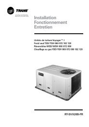
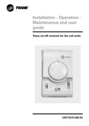
IntroductionTrane introduces the next generationof water-cooled helical rotarycompressor chillers, the RTHD.Continued RTHC features:• High energy efficiency• High reliability• Bolt together construction• R134a refrigerant• "Adaptive Control TM "With more than 10 years of screwcompressor development andmanufacturing experience, Tranepresents a new chiller with a higherefficiency and reliability than theunits available on today's market.New features:• CH.530 controls enable:- Scrolling access to inputs andoperating information via the LCDtouch-screen display- Freedom from interoperabilityconcerns with LonMark®communications- Job-specific communication optionsthat allow greater reportingflexibility• Improved startup temperaturecapabilities and reduced sensitivityto condenser water temperaturesalleviate the most common startupconcerns• Removed <strong>Liquid</strong> Vapor Separator,providing lighter unit weight andsimplified refrigerant piping, for lessexpensive handling, separation, andinstallationThe industrial-grade design of the<strong>Series</strong> R helical rotary chiller is idealfor both industrial and commercialmarkets, in applications such asoffice buildings, hospitals, schools,retail buildings, and industrialfacilities. The linear unloadingcompressor, wide operatingtemperature range, advancedcontrols, electronic expansion valve,short anti-recycle timers, andindustry-leading efficiencies meanthat this latest Trane <strong>Series</strong> R chiller isthe perfect choice for tighttemperature control in almost anyapplication temperatures, and underwidely varying loads.©American Standard Inc. 2003RLC-PRC023-E4
ContentsIntroduction 2Features and Benefits 4Application Considerations 6Selection Procedure 9General Data 12Electrical Data and Connections 15Dimensions and Weights 16Mechanical Specifications 20RLC-PRC023-E4 3
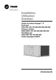
Application ConsiderationsCondenser Water RegulationThe Condenser Head PressureControl Option provides for a 0-10VDC (maximum range -a smallerrange is adjustable) output interfaceto the customer's condenser waterflow device. This option enables theCH530 controls to send a signal foropening and closing a 2-way or 3-way valve as necessary to maintainchiller differential pressure.Methods other than those shown canbe employed to achieve the sameresults. Contact your local Traneoffice for details.Throttling valveThis method maintains condensingpressure and temperature bythrottling water flow leaving thecondenser in response to condenserpressure or system differentialpressures.Advantages:• Good control with proper valvesizing at relatively low cost.• Pumping cost can be reduced.Disadvantages:• Increased rate of fouling due tolower condenser water velocity.• Requires pumps that canaccommodate variable flow.Disadvantage:• Higher cost because of thededicated pump required for eachchiller if condenser pressure is thecontrol signal.Figure 2Condenser water pump withvariable frequency driveAdvantages:• Pumping cost can be reduced.• Good tower temperature control.• Relatively low first cost.Disadvantage:• Increased rate of fouling due tolower water velocity in thecondenser.Figure 3Figure 1Cooling tower bypassTower bypass is also a valid controlmethod if the chiller temperaturerequirements can be maintained.Advantage:• Excellent control by maintainingconstant water flow through thecondenser.1 = Electric or pneumatic valveactuator2A = 3-way valve or 2 butterflyvalves2B = 2 butterfly valves3 = RTHD controller4 = Refrigerant pressure line5A = Condenser water pump5B = Condenser water pump withVFD6 = To/from cooling load7 = To/from cooling tower8 = Electric controller6 RLC-PRC023-E4
Application ConsiderationsVariable Evaporator Flow and ShortEvaporator Water LoopsVariable evaporator flow is anenergy-saving design strategy whichhas quickly gained acceptance asadvances in chiller and controlstechnology have made it possible.With its linear unloading compressordesign and advanced CH.530controls, the RTHD has excellentcapability to maintain leaving watertemperature control within+/- 0.28°C, even for systems withvariable evaporator flow and smallchilled water volumes.Some basic rules should be followedwhenever using these system designand operational savings methodswith the RTHD. The proper locationof the chilled water temperaturecontrol sensor is in the supply(outlet) water. This location allowsthe building to act as a buffer, and itassures a slowly changing returnwater temperature. If there isinsufficient water volume in thesystem to provide an adequatebuffer, temperature control can belost, resulting in erratic systemoperation and excessive compressorcycling. To ensure consistentoperation and tight temperaturecontrol, the chilled water loop shouldbe at least 2 minutes. If thisrecommendation cannot befollowed, and tight leaving watertemperature control is necessary, astorage tank or larger header pipeshould be installed to increase thevolume of water in the system.For variable primary flowapplications, the rate of chilled waterflow change should not exceed 10%of design per minute to maintain+/- 0.28°C leaving evaporatortemperature control.For applications in which systemenergy savings is most importantand tight temperature control isclassified as +/-1.1°C, up to 30%changes in flow per minute arepossible. Flow rates should bemaintained between the minimumand maximum allowed for anyparticular chiller configuration.<strong>Series</strong> Chiller ArrangementsAnother energy-saving strategy is todesign the system around chillersarranged in series, on theevaporator, condenser, or both. Theactual savings possible with suchstrategies depends on theapplication dynamics and should beresearched by consulting your TraneSystems Solutions Representativeand applying the Trane SystemAnalyzer program. It is possible tooperate a pair of chillers moreefficiently in a series chillerarrangement than in a parallelarrangement. It is also possible toachieve higher entering-to-leavingchiller differentials, which may, inturn, provide the opportunity forlower chilled water designtemperature, lower design flow, andresulting installation and operationalcost savings. The Trane screwcompressor also has excellentcapabilities for "lift", which affords anopportunity for savings on theevaporator and condenser waterloops.Like series arrangements on theevaporator, series arrangements onthe condenser may enable savings.This approach may allow reductionsin pump and tower installation andoperating costs. Maximizing systemefficiency requires that the designerbalance performance considerationsfor all system components; the bestapproach may or may not involvemultiple chillers, or seriesarrangement of the evaporatorsand/or condensers. This idealbalance of design integrity withinstallation and operating costconsiderations can also be obtainedby consulting a Trane representativeand applying the Trane SystemAnalyzer program.Water TreatmentThe use of untreated or improperlytreated water in chillers may result inscaling, erosion, corrosion, and algaeor slime buildup. It is recommendedthat the services of a qualified watertreatment specialist be engaged todetermine what treatment, if any, isadvisable. Trane assumes noresponsibility for the results of usinguntreated or improperly treatedwater.RLC-PRC023-E4 7
Application ConsiderationsWater PumpsWhere noise limitation and vibrationfreeoperation are important, Tranestrongly encourages the use of1450-rpm (50 Hz) pumps. Specifyingor using 3000-rpm (50 Hz) condenserwater and chilled water pumps mustbe avoided, because such pumpsmay operate with objectionablelevels of noise and vibration. Inaddition, a low frequency beat mayoccur due to the slight difference inoperating rpm between 3000-rpm(50 Hz) water pumps and <strong>Series</strong> Rchiller motors.Important Note:The chilled waterpump must not be used to stop thechiller.Acoustic ConsiderationsRefer to the Engineering BulletinRLC-PRB006 regarding SoundData/Installation Guide for Noise-Sensitive Applications for Tranewater-cooled helical-rotary chillers.Using the information provided inthis bulletin, contact a certifiedsound consultant to aid in propermechanical room design andtreatmentSound data given data in accordancewith ISO 3746-1996.8 RLC-PRC023-E4
Selection ProcedureChiller selections and performanceinformation can be obtained throughthe use of the <strong>Series</strong> R® <strong>Chillers</strong>election program.PerformanceThe computer selection programprovides performance data for eachchiller selection.Dimensional DrawingsThe dimensional drawings illustrateoverall measurements of the unit.Also shown are the serviceclearances required to easily servicethe RTHD chiller. All catalogdimensional drawings are subject tochange. Current submittal drawingsshould be referred to for detaileddimensional information. Contact thesales office for submittalinformation.Electrical Data TablesCompressor motor electrical data isshown in the data section for eachcompressor size. Rated load amperes(RLA), locked rotor Star-Deltaamperes (LRAY), the power factor forstandard voltages for all 50 Hz,3-phase motors are shown. The RLAis based on the performance of themotor developing full ratedhorsepower. A voltage utilizationrange is tabulated for each voltagelisted.Evaporator and Condenser PressureDropPressure drop data is determined bythe RTHD selection program.RLC-PRC023-E4 9
Selection ProcedureDigit 1-2-3-4-5: Chiller seriesRTHDE: Epinal RTHDDigit 6-7: Unit sizeB1-B2-C1-C2-D1-D2-D3-E3Digit 8: Main power voltageR: 380V/50Hz/3Ph +/-5%T: 400V/50Hz/3Ph +/-10%U: 415V/50Hz3PH +/-5%S: SpecialDigit 9: Other special requirementsX: NoS: YesDigit 13: Pressure vessel approvalP: PED (Pressure equipmentdirective)S: SpecialDigit 14-15: Evaporator sizeB1-C1-D1-D2-D3-D4-D5-D6-E1-F1-F2-G1-G2-G3Digit 17: Evaporator water passes2: 2 passes3: 3 passes4: 4 passes6: 6 passesS: SpecialDigit 18: Evaporator waterconnectionL: Left handR: Right handDigit 19: Evaporator connection typeA: VictaulicB: Victaulic + couplingS: SpecialDigit 20: Evaporator watersidepressureL: EVP 10 barH: EVP 21 barDigit 21-22: Condenser sizeB1-D1-E1-E2-E3-E4-E5-F1-F2-F3-G1-G2-G3Digit 23: Condenser tube typeA: Enhanced fin - copperB: Smooth bore - copperC: Smooth bore - 90/10 Cu/NiS: SpecialDigit 24: Condenser water passes2: 2 passesS: SpecialDigit 25: Condenser waterconnectionL: Left handR: Right handDigit 26: Condenser connection typeA: VictaulicB: Victaulic + couplingS: SpecialDigit 27: Condenser watersidepressureL: CDS 10 barH: CDS 21 barDigit 28: Condenser leaving watertemperatureA: Standard T < or = 45°CB: HI 45 < T < or = 50°CDigit 29: Refrigerant specialtiesX: WithoutG: GaugesV: Isolation valvesB: V+GDigit 30: Oil coolerX: WithoutC: WithDigit 31: Thermal insulationX: WithoutQ: Cold partsDigit 33: LanguageC: SpanishD: GermanE: EnglishF: FrenchH: DutchI: ItalianM: SwedishP: PolishT: CzechU: GreekV: PortugueseG: HungarianDigit 34: Safety devicesX: StandardB: Dual safety valvesA: B + rupture discDigit 35: Refrigerant chargeA: Full factory charge (R134a)B: Nitrogen (No oil)C: Holding charge (R134a)Digit 36: Shipping packageA: DomesticC: Domestic + skidE: SEI class 3F: SEI class 4aG: SEI class 4cS: SpecialDigit 37: Flow switchX: WithoutA: EvaporatorB: Evaporator + condenser.Digit 38: Factory testA: Functional testB: Customer inspectionC: Witness testD: Performance test with reportS: Special10 RLC-PRC023-E4
Selection ProcedureDigit 39: Starter typeY: Star-delta closed transition starterDigit 43: Power line connection typeA: Terminal blockB: Disconnect switch (No fuses)D: Circuit breakerK: Disconnect switch and fusesDigit 44: Electrical protectionB: StandardD: IP20 electrical protectionDigit 45: Electrical protectionX: StandardU: Under/over voltage protectionG: Ground fault protection relayB: U+GDigit 46: Unit operator interface(Dynaview)B: FrenchC: ItalianD: SpanishE: GermanF: DutchG: EnglishK: PortugueseDigit 47: Remote interfaceX: Without4: Tracer COMM 45: Tracer COMM 5 LCI-C (LonTalk)Digit 48: External chilled water +current limit setpointX: Without4: 4-20mA input2: 2-10Vdc inputDigit 49: External base loadingX: Without4: 4-20mA input2: 2-10Vdc inputDigit 50: Ice makingX: WithoutA: Ice making with relayB: Ice making without relayDigit 51: Programmable relaysX: WithoutR: Programmable relaysDigit 52: Chilled water resetX: StandardT: Chilled water reset - outdoor airtemperatureDigit 53: Reg. Valve & RLAX: WithoutD: Chiller differential pressure &%RLA outP: Condenser pressure (%HPC) & %RLA outV: Condenser reg. valve out & %RLAoutDigit 54: Refrigerant monitor inputX: WithoutA: 100ppm / 4-20mAB: 1000ppm / 4-20mAC: 100ppm / 2-10VdcD: 1000ppm / 2-10VdcRLC-PRC023-E4 11
General DataTable 1CompressorCodeEvaporatorCodeCondenserCodeEvaporatorCondenserR134aRefrigerantWater storage Water storage Charge(l) (l) (kg) (l)B1 B1 B1 155 106 186 17B1 C1 D1 208 117 222 17B2 B1 B1 155 106 186 17B2 C1 D1 208 117 222 17C1 D6 E5 170 110 222 23C1 D5 E4 197 121 222 23C1 D3 E3 295 178 222 23C2 D6 E5 170 110 222 23C2 D5 E4 197 121 222 23C2 E1 F1 310 226 238 38D1 D4 E4 197 121 222 23D1 D3 E3 295 178 222 23D1 G1 G1 515 299 318 42D2 D1 E1 261 166 215 23D2 F1 F2 386 216 284 38D2 G2 G1 545 299 318 42D3 D1 E1 261 166 215 23D3 F1 F2 386 216 284 38D3 G2 G2 545 344 318 42E3 D2 E2 280 178 215 23E3 F2 F3 405 231 284 38E3 G3 G3 602 367 318 42Oil ChargeTable 2 - Minimum/Maximum Evaporator Flow Rates (l/s)EvaporatorCode Min MaxTwo pass Three pass Four passSix passNominalConn. Size(mm) Min MaxNominalConn. Size(mm) Min MaxNominalConn. Size(mm) Min MaxB1 19 70 200 13 46 150 9 35 100 - - -C1 24 89 200 16 59 150 12 44 100 - - -D1 31 114 200 21 76 200 16 57 150 - - -D2 34 125 200 23 83 200 17 62 150 - - -D3 37 134 200 24 90 200 18 67 150 - - -D4 27 97 200 18 65 200 13 49 150 - - -D5 27 97 200 18 65 200 13 49 150 - - -D6 22 81 200 15 54 200 11 41 150 - - -E1 34 125 200 23 83 200 17 62 150 - - -F1 43 156 250 28 104 250 21 78 150 - - -F2 46 168 250 31 112 250 23 84 150 - - -NominalConn. Size(mm)G1 - - - 38 140 250 29 105 200 19 70 150G2 - - - 41 152 250 31 114 200 21 76 150G3 - - - 47 172 250 23 129 200 23 86 15012 RLC-PRC023-E4
General DataTable 3 - Minimum/Maximum Condenser Flow Rates (l/s)Two passCondenserCode Min. Max.NominalConn. Size(mm)B1 15 54 150D1 15 54 150E1 22 81 200E2 24 88 200E3 25 90 200E4 19 68 200E5 16 57 200F1 28 104 200F2 27 98 200F3 29 107 200G1 33 124 200G2 41 149 200G3 45 164 200Table 4 - Evaporator Water Pressure Drop (kPa)Evaporator2 passesWaterflow (l/s)20 25 30 35 40 45 50 55 60 65 70 75 80 85 90 95 100 105 110 115 120 125 130 135 140 145 150 155 160B1 9 14 20 26 33 40 49 58 68 79 90C1 11 15 20 26 32 38 45 53 61 70 80 90 100D1 7 11 15 18 22 27 31 36 41 46 52 58 64 71 78 86 94 102D2 7 10 13 16 20 24 28 32 36 41 46 51 57 63 69 75 81 88 95 103D3 5 8 10 13 16 19 23 26 30 34 38 42 47 51 57 62 67 73 79 85 92 99D4 13 17 21 27 32 38 45 52 60 68 76 86 95 105 116D5 13 17 21 27 32 38 45 52 60 68 76 86 95 105 116D6 7 11 15 20 26 32 39 46 54 63 72 82 92E1 7 10 13 16 20 24 28 32 36 41 45 50 56 61 67 73 79 86 93 100F1 7 9 12 15 18 21 24 27 31 35 39 43 47 52 57 62 67 72 78 84 90 96 102 109 115F2 7 9 11 14 17 20 23 27 31 35 39 43 48 53 58 64 70 76 82 88 95 102 110 117 125 133Table 5 - Evaporator Water Pressure Drop (kPa)Evaporator3 passes15 20 25 30 35 40 45 50 55 60 65 70 75 80 85 90 95 100 105 110 115 120 125 130 135 140 145 150 155 160B1 15 27 40 55 72 91 113C1 11 20 30 42 55 69 85 103 123 144D1 11 17 24 31 40 49 59 70 81 94 108 122D2 9 15 21 27 35 43 51 61 71 82 94 106 119D3 12 17 23 29 36 43 51 60 69 78 89 100 111 124D4 15 23 32 42 54 66 80 95 111 129D5 15 23 32 42 54 66 80 95 111 129D6 11 20 31 42 55 70 87 105 125E1 10 16 22 30 38 46 56 66 77 89 101 115 129Waterflow (l/s)F1 11 15 20 26 32 39 46 54 62 70 79 89 99 110 121 133F2 12 17 23 29 35 41 48 55 63 71 79 88 98 107 118 128 139G1 12 16 20 24 29 34 39 44 50 56 63 70 77 84 92 100 109 118 127 136 146G2 10 14 17 21 25 30 34 39 45 50 56 62 68 75 82 89 97 105 113 122 131 140 149G3 8 11 14 17 20 23 27 31 34 39 43 47 52 56 61 66 71 77 82 88 93 99 105 111 117 123RLC-PRC023-E4 13
General DataTable 6 - Evaporator Water Pressure Drop (kPa)Evaporator4 passes10 15 20 25 30 35 40 45 50 55 60 65 70 75 80 85 90 95 100 105 110B1 17 35 58 85 118C1 11 26 43 65 89 117 148D1 13 24 37 51 66 84 103 125 148D2 11 21 31 44 57 73 89 108 127 149D3 9 18 27 37 49 62 76 92 109 127 146D4 19 33 49 68 89 113 139D5 19 33 49 68 89 113 139D6 12 26 44 65 90 118 151E1 13 23 35 49 64 81 100 121 143Waterflow (l/s)F1 15 24 33 44 56 68 82 98 114 131 150F2 21 29 39 49 60 73 86 100 115 132 149G1 19 26 33 40 49 58 67 77 88 99 111 123 136G2 15 22 29 36 44 53 61 71 81 91 102 114 126 139G3 12 17 23 29 35 42 49 57 65 73 82 91 101 112 123 134 147Table 7 - Evaporator Water Pressure Drop (kPa)Evaporator6 passesWaterflow (l/s)20 25 30 35 40 45 50 55 60G1 28 43 60 79 99 122 147G2 24 37 52 68 86 105 127 150G3 18 29 41 55 69 85 103 121 142Table 8 - Condenser Water Pressure Drop (kPa)Condenser2 passes15 20 25 30 35 40 45 50 55 60 65 70 75 80 85 90 95 100 105 110 115 120 125 130 135 140 145 150 155 160B1 9 16 24 34 45 57 71 86 102D1 11 19 29 40 52 66 82 99 119E1 8 12 16 22 28 34 41 49 57 66 76 86 97E2 7 10 14 19 24 30 36 43 50 58 66 75 85 95E3 6 10 13 18 22 28 34 40 47 54 62 70 79 88 98E4 11 17 23 30 39 48 58 69 81 94E5 8 15 22 30 40 51 63 77 92Waterflow (l/s)F1 9 12 16 21 26 31 37 43 50 57 65 73 82 91 101 111 122F2 10 14 18 23 29 35 42 49 57 65 74 83 93 104 115 126F3 9 12 16 20 25 31 37 43 50 57 65 73 81 91 100 110 121G1 10 13 17 21 26 31 36 42 48 54 61 69 76 84 93 102 111 121 131G2 9 13 16 20 23 27 32 36 41 47 52 58 65 71 78 86 94 102 111 120 129 139 150G3 8 11 13 16 20 23 26 30 34 38 43 48 53 58 63 69 75 81 88 95 102 109 116 124 132 13914 RLC-PRC023-E4
Electrical Data and ConnectionsTable 9 - Compressor Motor Electrical Data - 50 Hz -Nominal VoltageCompressorCodeVoltageUtilizationRange380 400 415361-399 380-420 394-436B1 - B2 Max motor (kW) 139 145 148Max. RLA (A) 233 233 233Inrush current in star connection (A) 391 412 428Power factor 0.910 0.900 0.880C1 - C2 Max motor (kW) 201 209 213Max. RLA (A) 349 349 349Inrush current in star connection (A) 456 480 498Power factor 0.875 0.865 0.850D1 - D2 - D3 Max motor (kW) 271 280 284Max. RLA (A) 455 455 455Inrush current in star connection (A) 711 748 776Power factor 0.905 0.890 0.870E3 Max motor (kW) 288 301 306Max. RLA (A) 488 488 488Inrush current in star connection (A) 711 748 776Power factor 0.900 0.890 0.870Table 10 - Electrical ConnectionsCompressor Code B1 - B2 C1 - C2 D1 - D2 - D3 - E3Fuse size (A) (1) 250 400 500Disconnect switch size (A) (1) 250 400 630Minimum power cable cross section (1) (2) 95 185 2 * 150Maximum power cable cross section (1) (2) 240 240 2 * 300(1) Information for fused disconnect switch option only.(2) mm 2 /phase.RLC-PRC023-E4 15
Dimensions and WeightsTable 11CompressorCodeEvaporatorCodeCondenserCodeOperatingWeight(kg)ShippingWeight(kg)B1 B1 B1 4476 4215B1 C1 D1 4787 4462B2 B1 B1 4476 4215B2 C1 D1 4787 4462C1 D6 E5 6077 5797C1 D5 E4 6202 5884C1 D3 E3 6824 6351C2 D6 E5 6077 5797C2 D5 E4 6202 5884C2 E1 F1 7175 6639D1 D4 E4 6201 5883D1 D3 E3 6824 6351D1 G1 G1 8943 8129D2 D1 E1 6987 6551D2 F1 F2 7955 7353D2 G2 G1 8516 9360D3 D1 E1 6978 6551D3 F1 F2 7955 7353D3 G2 G2 9555 8666E3 D2 E2 7134 6676E3 F2 F3 8326 7690E3 G3 G3 9882 891316 RLC-PRC023-E4
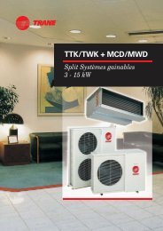
Dimensions and WeightsFigure 4RTHD B1 B1 B1RTHD B1 B2 B1Evaporator 3 passCondenser 2 passFigure 5RTHD B1 C1 D1RTHD B2 C1 D1Evaporator 3 passCondenser 2 pass1 = Minimum clearance for maintenance2 = Minimum clearance for tube removalRLC-PRC023-E4 17
Dimensions and WeightsFigure 6RTHD C1 D6 E5RTHD C1 D5 E4RTHD C1 D3 E3RTHD C2 D6 E5RTHD C2 D5 E4RTHD D1 D4 E4RTHD D1 D3 E3RTHD D2 D1 E1RTHD D3 D1 E1RTHD E3 D2 E2Evaporator 3 passCondenser 2 passFigure 7RTHD C2 E1 F1Evaporator 3 passCondenser 2 pass1 = Minimum clearance for maintenance2 = Minimum clearance for tube removal18 RLC-PRC023-E4
Dimensions and WeightsFigure 8RTHD D2 F1 F2RTHD D3 F1 F2RTHD E3 F2 F3Evaporator 3 passCondenser 2 passFigure 9RTHD D1 G1 G1RTHD D2 G2 G1RTHD D3 G2 G2RTHD E3 G3 G3Evaporator 4 passCondenser 2 pass1 = Minimum clearance for maintenance2 = Minimum clearance for tube removalRLC-PRC023-E4 19
Mechanical SpecificationsGeneralExposed steel surfaces shall bepainted with an air-dry beige paintprior to shipment. Each unit shallship with a full operating charge ofrefrigerant and oil. Molded neopreneisolation pads shall be supplied forplacement under all support points.Startup and operator instructions byfactory-trained service personnel areincluded.Compressor and MotorThe unit shall have a semi-hermeticdirect- drive, 3000 rpm, rotarycompressor with capacity controlslide valve, oil sump heater anddifferential pressure refrigerant oilflow system. Four pressurelubricated rolling element bearinggroups shall support the rotatingassembly. Motor shall be a suctiongas cooled, hermetically sealed, twopole, squirrel cage induction type.Evaporator-CondenserAll tube sheets shall be carbon steelplate. Evaporator and condensertubes should be individuallyreplaceable. Standard tubes shall beexternally finned, internallyenhanced seamless copper withlands at all tube sheets. Evaporatortubes shall be 25.4 mm diameter.Condenser tubes shall be 19.05 mmdiameter. Tubes shall bemechanically expanded into tubesheets. Condenser and evaporatortubes shall be mechanically fastenedto tube supports. The water boxesshall be cast iron or fabricated steelavailable with Victaulic connections.Refrigerant CircuitAn electronically controlledexpansion valve shall be provided tomaintain proper refrigerant flow.Unit Controls (CH.530)The microprocessor-based controlpanel is factory-installed and factorytested.The control system ispowered by a control powertransformer, and will load andunload the chiller throughadjustment of the compressor slidevalve. Microprocessor-based chilledwater reset based on return water isstandard. The CH.530 utilizing the"Adaptive Control TM " microprocessorautomatically shall take action toprevent unit shutdown due toabnormal operating conditionsassociated with low evaporatorrefrigerant temperature, highcondensing temperature, and motorcurrent overload. If the abnormaloperating condition continues andprotective limit is reached, themachine will be shut down. Thepanel shall include machineprotection shutdown requiringmanual reset for:• Low evaporator refrigerantTemperature and pressure• High condenser refrigerantpressure• Low oil flow• Critical sensor or detection circuitfault• Motor current overload• High compressor dischargetemperature• Communications lost betweenmodules• Electrical distribution faults: phaseloss, phase imbalance, phasereversal• External and local emergency stop• Starter transition failure.The panel shall include machineprotection shutdown with automaticreset when the condition is correctedfor:• Momentary power loss• Over / under voltage• Loss of evaporator or condenserwater flow.Over 100 diagnostic checks shall bemade and displayed when a fault isdetected. The display shall indicatethe fault, the type of reset required,the time and date the diagnosticoccurred, the mode in which themachine was operating at the time ofthe diagnostic, and a help message.A diagnostic history shall display thelast 20 diagnostics with the time anddate of their occurrence.20 RLC-PRC023-E4
Mechanical SpecificationsClear Language DisplayPanelFactory-mounted to the control paneldoor, the operator interface has anLCD touch-screen display foroperator input and informationoutput. This interface provides accessto the following information:evaporator report, condenser report,compressor report, operator settings,service settings, service tests, anddiagnostics. All diagnostics andmessages are displayed in "clearlanguage." Data contained inavailable reports includes:• Water and air temperatures• Refrigerant levels and temperatures• Oil pressure• Flow switch status• EXV position• Head pressure control command• Compressor starts and run-time• Line phase percent RLA, amps, andvoltsAll necessary settings and setpointsare programmed into themicroprocessor-based controller viathe operator interface. The controlleris capable of receiving signalscontemporaneously from a variety ofcontrol sources, in any combination,and priority order of control sourcescan be programmed.The control source with prioritydetermines active setpoints via thesignal it sends to the control panel.Control sources may be:• the local operator interface(standard)• a 4-20 mA or 2-10 VDC signal froman external source (interfaceoptional; control source notsupplied)• Trane Tracer Summit system(interface optional)• Generic BAS (optional points;control source not supplied)• LonTalk LCI-C (interface optional;control source not supplied)Unit-Mounted StarterThe starter is available in a Star-Deltaconfiguration, factory-mounted andfully pre-wired to the compressormotor and control panel. A factoryinstalled,factory-wired 600VAcontrol power transformer providesall unit control power (120 VACsecondary) and CH.530 modulepower (24 VAC secondary). Optionalstarter features include circuitbreaker, fused disconnect switch,non-fused disconnect switch.OptionsDisconnect switchOptional starter features includecircuit breaker, fused disconnectswitch, non fused disconnect switch.The disconnect switch is alsomechanically interlocked todisconnect line power from thestarter before the starter door isopen.Nitrogen ChargeUnit is shipped with a nitrogenholding charge in lieu of refrigerant(No oil charge).Holding chargeUnit is shipped with a holding R134acharge and full oil charge.InsulationAll low temperature surfaces arecovered with 19 mm of armaflex(K=0.28), including the evaporatorand water boxes, suction line andmotor housing .Cupronickel condenser tubesCupronickel condenser tubes areavailable for special applications.90/10 cupronickel tubes are ¾"diameter and 0.035" wall thickness.RLC-PRC023-E4 21
Mechanical SpecificationsProgrammable Relays (Alarm andStatus)CH.530 provides a flexible alarm orchiller status indication to a remotelocation through a hard wiredinterface to a dry contact closure.Four relays are available for thisfunction, and they are provided(generally with a Quad Relay OutputLLID) as part of the Alarm RelayOutput Option. The events/states thatcan be assigned to theprogrammable relays are listed inthe installation manual RLC-SVX05A.External Base LoadingPrimarily for process controlrequirements, base loading providesfor immediate start and loading of achiller up to an externally orremotely adjustable current limitsetpoint without regard todifferential to start or stop, or toleaving water temperature control.This allows the flexibility to prestartor preload a chiller in anticipation ofa large load application. It alsoallows you to keep a chiller on linebetween processes when leavingwater temperature control wouldnormally cycle the unit.Summit InterfaceCH.530 provides an optionalinterface between the chiller and aTrane Summit BAS.A Communications interface LLIDshall be used to provide "gateway"functionality between the Chiller andSummit.LonTalk Communication InterfaceCH.530 provides an optional LonTalkCommunication Interface (LCI-C)between the chiller and a BuildingAutomation System (BAS). AnLCI-C LLID shall be used to provide"gateway" functionality between theLonTalk protocol and the Chiller.Ice Making ControlCH.530 accepts a contact closureinput to initiate Ice Building. When inthe ice building mode, thecompressor will be fully loaded (notgiven a low setpoint) and willcontinue to operate until the icecontacts open or the return watertemperature reaches the IceTermination Setpoint. If terminatedon return setpoint, CH.530 will notallow the chiller to restart until theice making contact is opened.Ice Machine ContactCH.530 provides an output contactclosure that can be used as a signalto the system that ice building is inoperation. This relay will be closedwhen ice building is in progress andopen when ice building has beenterminated by either CH.530 or theremote interlock. It is used to signalthe system changes required toconvert to and from ice making.External Chilled Water SetpointCH.530 will accept either a 2-10 VDCor a 4-20mA input signal, to adjustthe chilled water setpoint from aremote location.External Current Limit SetpointCH.530 will accept either a 2-10VDCor a 4-20mA input signal to adjustthe current limit setpoint from aremote location.Percent Condenser Pressure OutputCH.530 provides a 2-10 VDC analogoutput to indicate percent HighPressure Cutout (HPC) condenserpressure.Percent HPC = (CondenserPressure/High Pressure CutoutSetpoint)*100Compressor Percent RLA OutputCH.530 provides a 0-10 Vdc analogoutput to indicate %RLA ofcompressor starter average phasecurrent. 2 to 10 Vdc corresponds to 0to 120%RLA.22 RLC-PRC023-E4
NotesRLC-PRC023-E4 23
TraneA business of American Standard Companieswww.trane.comFor more information contact your localdistrict office or e-mail us at comfort@trane.comLiterature Order NumberRLC-PRC023-E4Date 0803SupersedesNewStocking LocationEuropeTrane has a policy of continuous product and product data improvement and reserves the right tochange design and specifications without notice. Only qualified technicians should perform theinstallation and servicing of equipment referred to in this publication.Société Trane – Société Anonyme au capital de 61 005 000 Euros – Siege Social: 1 rue des Amériques –88190 Golbey – France – Siret 306 050 188-00011 – RSC Epinal B 306 050 188Numéro d’identification taxe intracommunautaire: FR 83 3060501888