Thermal Management Solutions for Electronics - Arlon MED
Thermal Management Solutions for Electronics - Arlon MED
Thermal Management Solutions for Electronics - Arlon MED

Create successful ePaper yourself
Turn your PDF publications into a flip-book with our unique Google optimized e-Paper software.
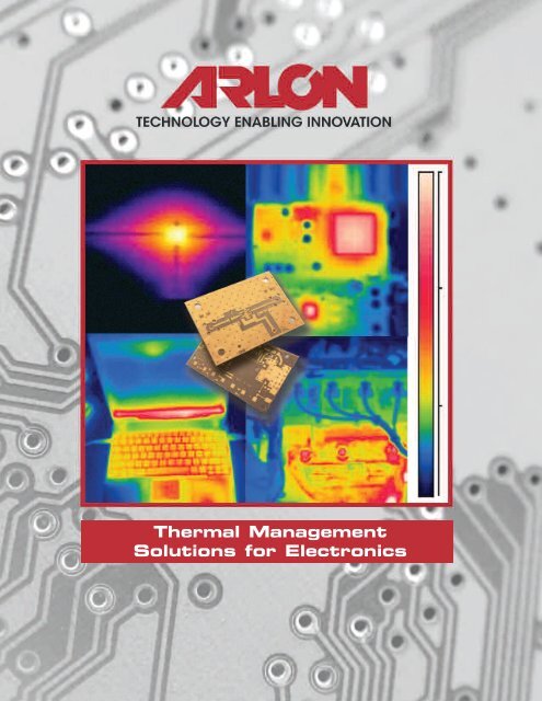
<strong>Thermal</strong> <strong>Management</strong><br />
<strong>Solutions</strong> <strong>for</strong> <strong>Electronics</strong>
INTRODUCTION<br />
Whether in consumer electronics or high-end aerospace technology, printed<br />
wiring board assemblies <strong>for</strong> today’s increasingly complex electronics present<br />
design engineers with an ever growing need <strong>for</strong> improved, cost-effective thermal<br />
management. Many industry trends, such as cost reduction pressures, reduced<br />
footprints, and reduced weight, are counterbalanced by the need <strong>for</strong> higher circuit<br />
density to provide increased functionality to support more user “features.” The<br />
end result is an increase in heat generated—an a growing need <strong>for</strong> improved,<br />
cost-effective thermal management.<br />
Typical applications include:<br />
• Defense & Aerospace<br />
• High brightness LED’s<br />
• Automotive <strong>Electronics</strong><br />
• Power Converters<br />
• Chemical & Process Industry instrumentation<br />
• Telecommunications Infrastructure<br />
• Cell phones & feature-rich consumer electronics<br />
• High power RF combiner/splitters & power amplifiers<br />
• Semiconductor chip packaging<br />
• Server backplanes<br />
To meet the design challenges of these diverse applications, material<br />
options have evolved to provide engineers with a broader and more versatile tool<br />
kit to optimize device cost, per<strong>for</strong>mance and reliability. <strong>Arlon</strong>’s electronic<br />
materials have been engineered to enhance thermal management to ultimately<br />
improve device reliability. <strong>Arlon</strong>’s broad product-line of PWB materials offers<br />
design engineers access to multiple and enhanced thermal management stratgies<br />
to meet the end-use requirements, from overall cost reduction to mission critical<br />
per<strong>for</strong>mance.<br />
THESE DESIGN STRATEGIES INCLUDE:<br />
Removing the Heat – Many designs today continually push limits <strong>for</strong> heattransfer,<br />
resulting in high device operating temperatures. Newer <strong>Arlon</strong> PCB materials offer<br />
increased thermal conductivity to reduce peak operating temperatures and<br />
improve component life.<br />
Beating the Heat – For over 30 years, high temperature applications have used<br />
Polyimide laminate & prepreg systems to provide device reliability in operating environments<br />
exceeding 200°C. <strong>Arlon</strong>’s new EP2 enhanced polyimide system and<br />
newer lead-free compatible thermally conductive epoxy systems offer designers<br />
new approaches to maximizing reliability in tough operating environments.<br />
Surviving the Environment – How materials respond to cyclic thermal exposure<br />
remains a critical contributing factor in determining device reliability. Designing<br />
PWB’s on materials that reduce or control thermal expansion will improve PTH<br />
reliability and reduce stress and fatigue on solder joints to SMT components.<br />
Reducing the Heat – Low loss materials <strong>for</strong> microwave & High Frequency<br />
applications minimize heat generated by transmission line loss.
Table of Contents:<br />
<strong>Thermal</strong> <strong>Management</strong>—Designing <strong>for</strong> Reliability ..............................................................<br />
Understanding Heat Transfer ............................................................................................<br />
<strong>Thermal</strong> <strong>Management</strong> Options ..........................................................................................<br />
Optimization ......................................................................................................................<br />
Surviving the Environment..................................................................................................<br />
High Temperature <strong>Electronics</strong><br />
<strong>Thermal</strong> Cycling & Reliability<br />
Additional Material Considerations<br />
Microwave & RF System ....................................................................................................<br />
10<br />
<strong>Thermal</strong> Interface Materials ..............................................................................................<br />
13<br />
Abbreviations and Reference Formulas ............................................................................<br />
14<br />
<strong>Arlon</strong> Material Options ......................................................................................................<br />
16<br />
1<br />
3<br />
4<br />
5<br />
6
1<br />
<strong>Thermal</strong> <strong>Management</strong>: Designing <strong>for</strong> Reliability<br />
Device reliability is a complex function of the heat generated by the operation of an electronic<br />
device, the tools used to dissipate or manage the heat, the thermal stability of the materials used<br />
and the environment in which the device is required to operate. Because of diversity of applications and<br />
the increasing demand <strong>for</strong> electronics, diverse thermal management tools have evolved to help mitigate<br />
reliability issues. These tools include gap fillers, active cooling systems, heat pipes and heat sinks.<br />
While many of these tools overlap in terms of potential benefits, the selection of which tools to apply<br />
depends on the ultimate constraints of the device in terms of cost, power requirements, weight, size and<br />
reliability. <strong>Arlon</strong>’s Electronic Materials product line has long been a part of this solution set, including<br />
low-loss materials <strong>for</strong> high frequency applications, polyimide materials used in high temperature<br />
electronics, and silicone thermal interface materials. Recently, <strong>Arlon</strong> has expanded the technology<br />
options through the development of engineered thermally conductive laminate & prepreg systems <strong>for</strong><br />
multilayer printed circuit board applications. The breakdown of a typical electronic device<br />
demonstrates the various tools used to facilitate heat dissipation when designing <strong>for</strong> reliability.<br />
Diagram 1 below shows a generic device with an active component mounted on a typical circuit<br />
board. Complementing these active components may be heat sinks, thermal interface materials,<br />
thermal vias and active cooling systems. Many of these approaches are implemented to compensate<br />
<strong>for</strong> the fact that most traditional electronic components and dielectric materials are thermal insulators,<br />
necessitating secondary cooling systems, such as heat sinks and cooling fans. <strong>Thermal</strong> interface<br />
materials are used to minimize gaps or variation between materials that can occur in assembly, which<br />
can retard heat transfer.<br />
Diagram 1: Typical Device Breakdown<br />
Device<br />
Enclosure<br />
Printed Circuit<br />
Board<br />
<strong>Thermal</strong> Interface<br />
Material<br />
(Optional)<br />
Heat Sink<br />
EMI Shield<br />
(Optional)<br />
Active Component(s)<br />
Cooling Fan<br />
(Optional)<br />
Heat Spreader<br />
Silicon Chip<br />
<strong>Thermal</strong><br />
Vias<br />
Dielectric<br />
Layers<br />
Heat Sink<br />
<strong>Thermal</strong> Interface<br />
Material<br />
Solder Mask<br />
or<br />
Hermetic<br />
Seal<br />
Copper<br />
Traces
<strong>Thermal</strong> <strong>Management</strong> — Continued<br />
Selection and optimization of thermal management tools are often based on a combination of<br />
experience, knowledge and device testing to understand failure mechanisms. Device failure is a<br />
function of the reliability of the components, materials, time and operating environment (humidity,<br />
temperature, thermal cycling, etc.). In most cases failures can be grouped into one of several<br />
categories, such as component failure, connector/solder joint failure, or board failure, to facilitate<br />
further root cause analysis. Ultimate causes of these failures may include chemical or<br />
electrical degradation of base materials, connection failures caused by thermal expansion<br />
mismatches, air gaps causing a reduction in heat transfer, oxidation caused by high temperature or<br />
mechanical failures. One cause of temperature related failures of boards or components relates to<br />
change or degradation at the molecular level. This type of failure is best modeled as a first order<br />
kinetic reaction, typically described as an Arrhenius Equation, which is proportional to the inverse log<br />
of the temperature. A simplified Arrhenius equation and a resulting reliability plot against<br />
operating temperature are displayed in Diagram 2. Since failure rates, often described as a<br />
mean-time-to-failure (MTTF), increase exponentially with temperature, a 10°C increase in temperature<br />
can double the failure rate. In an operating device where reliability is critical to success, even 1°C can<br />
matter. The key to improving reliability is to reduce device temperature by increasing the rate at<br />
which heat is removed from the device and from the working area of the PWB immediately adjacent<br />
to the device. Understanding heat transfer then becomes the next step.<br />
Diagram 2: Arrhenius Equation & Reliability Chart<br />
Hours<br />
1.E +06<br />
1.E +05<br />
1.E +04<br />
1.E +03<br />
1.E +02<br />
1.E +01<br />
1.E +00<br />
100<br />
110<br />
120<br />
Log Plot Temp vs. Time<br />
130<br />
140<br />
150<br />
160<br />
Temp (C)<br />
170<br />
180<br />
190<br />
200<br />
2<br />
210
3<br />
Understanding Heat Transfer<br />
Heat is generated every time an active device is in operation. Device operating temperature is a result<br />
of the balance between heat generation and heat dissipation. Heat itself does not become a problem<br />
until there is enough heat to result in an increase in temperature above a critical point, in many cases<br />
about 105 to 120°F. Since many designs are set based on function, the heat generation side of the<br />
equation is already determined by the time it comes to managing heat dissipation. As such, it is<br />
important to understand the basics of heat transfer to determine possible strategies <strong>for</strong> reducing<br />
device temperature. In simple terms, the whole business of managing heat in a PWB assembly is<br />
about preventing the junction temperature from getting high enough to “fry” the active devices.<br />
Heat is moved from a “hot” body to a cooler body by one of three basic modes: conduction,<br />
convection or radiation. In a PWB assembly, all three are in play to one degree or another.<br />
Conduction can be the most effective <strong>for</strong> heat transfer, where the cooler body is in direct (and<br />
preferably intimate) contact with the warmer one and the heat moves from hot to cold materials in an<br />
attempt to reach equilibrium. The rate at which heat is carried from one to the other depends on the<br />
thermal (temperature) gradient, the coefficient of heat transfer of materials involved (thermal<br />
conductivity), the amount of material involved in the thermal path (thickness), the quality of the<br />
interface and to a lesser extent, the heat capacity of the “cool body” that is absorbing the heat. The<br />
combined effects of thermal conductivity, the material thickness in the thermal path and the interface<br />
effects on heat flow is often characterized in terms of the thermal impedance.<br />
Convection is the transfer of heat from a hot body to a cooler fluid which carries it away through<br />
molecular motion. This can happen naturally in a fluid based on resulting density gradients caused<br />
by temperature variation. Convection may be aided by <strong>for</strong>cing the cooling fluid to flow past the warm<br />
body, thus carrying away the heat faster. Conversely, convection heat transfer can be significantly<br />
impeded by device enclosures that restrict air flow, resulting in higher device temperatures.<br />
Radiation is the removal of heat from a body by the emission of energy in the <strong>for</strong>m of<br />
electromagnetic radiation, which may be in the infrared (heat) or even visible (light) parts of the<br />
spectrum depending on the temperature of the radiating body. RF signals, such as those generated<br />
by an antenna, are also a type of radiation that dissipates energy.<br />
Heat Transfer Models
<strong>Thermal</strong> <strong>Management</strong> Design Options<br />
The number of approaches and possible solutions to reduce temperature through heat removal from<br />
active devices is almost endless. This remains an active area <strong>for</strong> development across all application<br />
areas and the tools available to designers will continue to evolve. While <strong>Arlon</strong> does not participate<br />
in all of these areas, this section covers some basic approaches, highlighting some common tools<br />
with a brief summary of their advantages & disadvantages.<br />
Tools <strong>for</strong> increasing Convection<br />
• Active Cooling – Forced Air, Conditioned Air<br />
• Water Cooled, Vapor Cooled, direct, indirect<br />
While active systems, such as cooling fans, may be extremely effective in heat removal, they add<br />
additional design & power requirements, increase costs, and add to device size & weight. They also<br />
add to potential reliability concerns as failures of these systems typically result in device failures.<br />
Tools <strong>for</strong> increasing Conduction<br />
• Heat Sinks, Heat Spreaders, Heat Risers & Heavy Metal Backplates<br />
• <strong>Thermal</strong> Vias (PTH used to leverage thermal conductivity of copper)<br />
• <strong>Thermal</strong> Coins (Inserts of metal conductors in PCB cut-outs under active components to improve<br />
heat transfer)<br />
• <strong>Thermal</strong> Interface Materials, <strong>Thermal</strong>ly Conductive Adhesives, Gap Fillers, Grease, etc.<br />
• <strong>Thermal</strong>ly Conductive Printed Circuit Board Materials<br />
Each of these tools brings its own advantages & disadvantages. Heat-sinks and backplates add cost<br />
and weight to a system. Design & optimization of these systems requires a consideration of the metallurgy<br />
(usually copper, brass or aluminum) to balance heat transfer requirements with material<br />
thermal conductivity, heat capacity, density, machinability, processing requirements and costs.<br />
<strong>Thermal</strong> vias can be extremely cost effective, but there are practical limits in the area covered. Heat<br />
transfer in thermal vias is limited to thru-plane heat transfer and can cause reliability concerns if the<br />
PTH’s fail due to stresses from thermal expansion. <strong>Thermal</strong> coins are potentially more cost-effective<br />
than a large heat-sink and potentially more reliable than thermal vias, but they add to assembly<br />
complexity and costs.<br />
<strong>Thermal</strong> interface materials can be either electrically conductive or electrically insulating and cover a<br />
wide variety of materials, such as thermal pastes, greases, phase change materials, tapes, bonding<br />
plies, and prepregs. Their primary advantage is that they can displace air gaps & reduce impedance<br />
to heat flow at interfaces. Some types of materials can also offer thermal-mechanical de-coupling to<br />
minimize stresses from thermal expansion, and to reduce vibration related failures or joint failures and<br />
improve reliability through thermal cycling.<br />
Circuit board thermal conductivity is often neglected as a potential area to improve heat transfer since<br />
this has historically not been a controllable design option. The primary purpose of these materials are<br />
to provide electrical isolation of the various components and traces. This has yielded materials that<br />
are also good thermal insulators which trap heat within the active components of the board. By<br />
4
5<br />
Design Options — Continued<br />
modifying the base properties of these materials, <strong>Arlon</strong> created materials that provide not only the<br />
electrical insulation required <strong>for</strong> typical circuit boards, but also improve heat transfer rates relative to<br />
traditional materials. This benefit is demonstrated in the following tests, comparing a traditional<br />
FR-4 materials with laminates of increasing thermal conductivity in the same circuit design with a<br />
0.5 Watt heat source. As thermal conductivity is increased, so is the heat transfer rate, resulting in a<br />
lower peak temperature by over 50°F (30°C).<br />
Practical Application — 0.5 W Heat Source<br />
(0.3, 1.0 & 2.0 W/m-K)<br />
Top<br />
Max at 210°F (99°C) Max at 182°F (83°C) Max at 155°F (68°C)<br />
Bottom<br />
Max at 200°F (93°C) Max at 170°F (77°C) Max at 138°F (56°C)<br />
FR4<br />
91ML<br />
92ML<br />
Heat spreading associated with 92ML is related to<br />
higher TCxy vs TCz (2X)<br />
Optimization<br />
Design optimization usually begins with thermal modeling tools to identify hot spots or other issues.<br />
There are several good software packages on the market today that can help designers understand<br />
the effects and trade-offs of the various thermal management tools. This can be time consuming and<br />
requires a good understanding of the model limitations to fully translate the results into practice.<br />
Un<strong>for</strong>tunately most modeling software assumes isotropy which may result in over or underestimation<br />
of the heat removal. In most PCB materials, the heat transfer coefficient in the perpendicular<br />
direction (down through the PWB) is different from that in the plane of the board. The models also<br />
rarely account <strong>for</strong> potential issues, complications or variation in materials, fabrication or assembly.<br />
Interfaces interfere with the heat transfer mechanism, through imperfections in conduction. This often<br />
results in reduced efficiency in heat transfer and results in excessive temperatures. Addressing these<br />
potential issues is generally where actual thermal testing of sub-assemblies & devices can help. Such<br />
testing can be as simple as power cycling or single point thermocouple measurements, all the way to<br />
sophisticated thermal imaging equipment. Testing can help designers further optimize their designs<br />
by identifying potential problems or lower cost substitutions, such as trade-offs in materials choice<br />
(aluminum vs copper, cast vs machined heat sinks, etc.).
Surviving the Environment<br />
The first step towards ensuring long term survivability of a device in a thermally stressing environment<br />
is to select materials that can meet the thermal excursions in the PWB manufacturing & assembly<br />
process. IPC specifications <strong>for</strong> “Lead-Free” & “High Reliability” materials include such factors as Tg<br />
(glass transition temperature), Td (thermal decomposition temperature), total thermal expansion<br />
perpendicular to the plane of the board (Z-axis) and short term stress tests such as T260, T288 and<br />
T300. The key to success is to avoid latent defects such as hidden cracks in PTH copper that can<br />
later propagate and cause resistance change or opens when the board is at operating temperature.<br />
Arguably, Tg is usually the first consideration in material selection as it relates to the survivability of<br />
PTH’s during thermal cycling. A high Tg material will exhibit lower overall Z-expansion from room<br />
temperature to the operating temperature, and will normally retain its adhesion to copper up to and<br />
even somewhat beyond the Tg. Z-Axis thermal expansion from 60-260°C is also a key metric in<br />
comparing materials <strong>for</strong> potential PTH reliability.<br />
Decomposition Temperature (Td) is a determinant in assessing long term survivability of materials at<br />
elevated temperatures, and while the temperature of a PWB rarely reaches anything approaching its<br />
Td, it is reasonable to say that a material with a high Td is likely more survivable at any long term<br />
temperature exposure than a material with a lower Td.<br />
T260, T288 and T300 tests are good measures of the likelihood of a PWB substrate surviving<br />
short-term exposure at the extreme thermal limits. These tests are measured by ramping samples to<br />
the specified temperature and holding them isothermally until irreversible change occurs, usually in<br />
the <strong>for</strong>m of delamination.<br />
Other factors such as water absorption (hence the impact of the relative humidity), resistance to<br />
various process and environmental chemistries, ozone resistance, etc. may have additional roles to<br />
play, although few of them have been analyzed in depth in terms of long term operation of a PWB.<br />
LAMINATE PERFORMANCE<br />
FACTOR<br />
Glass Transition Temperature (Tg) • Strongest factor in determining total z-axis expansion<br />
• Higher Tg related to greater PTH reliability<br />
z-axis Expansion (CTE z) • Lower (CTE z)<br />
related to PTH reliability, but total z-axis<br />
expansion more important<br />
Decomposition Temperature (Td) • Primarily affects catastrophic laminate failure during<br />
assembly or rework<br />
• Not necessarily related to per<strong>for</strong>mance over time on<br />
sustained exposure to high temperature in actual use<br />
Time at Temperature<br />
(T260/T288/T300)<br />
PERFORMANCE IMPACT<br />
• Measure of time to delaminate at a specific temperature<br />
(260, 288 or 300°C)<br />
• Related to per<strong>for</strong>mance over time on sustained exposure<br />
to high temperature in actual use<br />
6
7<br />
Surviving the Environment — Continued<br />
Other factors such as water absorption (hence the impact of the relative humidity), resistance to<br />
various process and environmental chemistries, ozone resistance, etc. may have additional roles to<br />
play, although few of them have been analyzed in depth in terms of long term operation of a PWB.<br />
The following table of properties of <strong>Arlon</strong>’s PWB materials will give a sense of the range of the key<br />
thermal mechanical and chemical properties available to the designer. Note particularly the thermal<br />
conductivity of standard vs. thermally conductive materials.<br />
Product Type<br />
Preliminaryy<br />
IPC Pb-F<br />
ree<br />
Spec (/124)<br />
33N 35N 85N EP2 45N 91ML 92ML<br />
Polyimide Polyimide Polyimide Polyimide Enhanced DiCy TC TC<br />
UL-94 VO UL-94 V1 UL-94 HB Polyimide<br />
Epoxy Epoxy Epoxy<br />
Glass Transition (Tg) °C >155 250 250 260 250 175 170 170<br />
T260 min >30 >60 >60 >60 >60 8 >60 >60<br />
T288 min >15 23 >60 >60 15 0 >30 >15<br />
T300 min >2 8 11 >60 10 0 >10 >5<br />
Td (i nitial) °C 353 363 387 363 299 354 340<br />
Td (5%) °C >330 389 407 407 424 311 368 400<br />
CTE z (
Surviving the Environment — Continued<br />
100000<br />
10000<br />
1000<br />
100<br />
10<br />
PTH Reliability — Mean Cycles to Fall<br />
"Field Life"<br />
"ATC Life"<br />
FR/4 Blend D<br />
Low Loss X<br />
FR/4 Resin A<br />
Polyimide Y<br />
"Assembly Life"<br />
1<br />
100 120 140 160 180 200 220 240 260<br />
Source:<br />
High Temperature<br />
Proof is in the PTH —<br />
Assuring Via Reliability from Chip Carriers to Thick Printed Wiring Boards<br />
Kevin T. Knadle and Virendra R. Jadhav,<br />
Endicott Interconnect Technologies, Inc<br />
Paper presented at the 2005 Electronic Components and Technology Conference<br />
<strong>Thermal</strong> Cycling & Reliability<br />
<strong>Thermal</strong> cycling can be caused by device on/off<br />
cycles or from the operating environment, such as<br />
day/night temperatures, seasonal temperature<br />
changes, or satellite orbits, etc. These temperature<br />
cycles can cause additional thermal stresses on a<br />
PCB, particularly on the plated through holes (PTH).<br />
Temperature cycles can range as much as 150°C and<br />
cause significant failures. High ambient temperature<br />
during peak cycles also reduce heat transfer and can<br />
result in higher device temperatures without<br />
additional design consideration.<br />
In terms of PTH reliability, materials with low thermal expansion rates can minimize copper fatigue and<br />
reduce failure rates. The greater the severity in the thermal cycle, the greater the influence of the<br />
material on reliability. Polyimide materials and filled epoxy systems with low Z-axis expansion rates<br />
are often used in these applications to extend PTH life.<br />
Heat transfer influences the peak operating temperature of a device, which in turn influences the peak<br />
operating temperature during thermal cycling. <strong>Thermal</strong>ly conductive substrates such as 91ML<br />
(1.0 W/m-K) or 92ML (2.0 W/m-K) help remove heat from hot spots and active devices, but also<br />
spread the heat out over a wider area so that the temperature within the device is noticeably reduced.<br />
Reductions in temperature through the use of thermally conductive substrates will not only greatly<br />
increase the survivability of operating devices (which double in service life <strong>for</strong> every 10°C of<br />
temperature reduction at the junction), but will slow surface oxidation of the resin system which also<br />
degrades its per<strong>for</strong>mance in a similar manner.<br />
Additional Material Considerations<br />
There are several factors which will determine the degree of survivability of a PWB and the compo-<br />
nents mounted on it, given the temperature extremes<br />
& the heat cycling it undergoes. The inherent<br />
properties of the substrate material such as decomposition<br />
temperature, glass transition temperature,<br />
resistance to thermal oxidation (and this is one that<br />
can be a subtle killer, since oxidation resistance is not<br />
included in any specifications <strong>for</strong> PWB materials),<br />
MOT (as determined by UL multipoint ageing tests<br />
and extrapolated out to 100,000 hours), retention of<br />
copper peel strength at elevated temperatures, etc.<br />
are the baseline <strong>for</strong> surviving use temperatures.<br />
Hours<br />
1.E+06<br />
1.E+05<br />
1.E+04<br />
1.E+03<br />
1.E+02<br />
1.E+01<br />
1.E+00<br />
110<br />
100<br />
UL Long-Term Termal Aging<br />
Log Plot Temp vs. Time<br />
130<br />
120<br />
150<br />
140<br />
170<br />
160<br />
Temp (C)<br />
190<br />
180<br />
210<br />
200<br />
8
9<br />
Surviving the Environment — Continued<br />
While the UL Relative <strong>Thermal</strong> Index may not identify the ultimate use temperature of a material, it is<br />
a good starting point reference as it measures the decline in electrical or mechanical strength at<br />
elevated temperature. Use above that temperature can result in increasingly rapid failure (the rate of<br />
any chemical reaction roughly doubles <strong>for</strong> every 10°C as previously discussed). The UL plot is logarithmic<br />
and can provide a relative impact on reliability with an increase (or decrease) in temperatures.<br />
Oxidation is the principal mechanism by which epoxies and polyimides embrittle and turn brown as<br />
they sit or operate at high temperatures over a period of time. Above the Tg of the material, this<br />
process occurs more rapidly because of greater diffusion rates and more molecular motion. With<br />
polyimide, <strong>for</strong> example, although it turns brown fairly quickly, this is mostly a surface oxidation and<br />
not a deep deterioration of the material. Lower temperature materials, such as epoxies with fairly<br />
labile bromine and the like will deteriorate substantially at temperatures which are relatively harmless<br />
to polyimide. Oxidation rates can be further reduced through the use of con<strong>for</strong>mal coatings that can<br />
protect copper & dielectric materials to improve reliability at higher higher temperatures or<br />
elevated humidity.<br />
Board-specific stress testing such as IST (Interconnect Stress Testing), HATS (Highly Accelerated<br />
<strong>Thermal</strong> Shock) and HAST (Highly Accelerated Temperature and Humidity Stress Testing) are used to<br />
give an estimate of the long term survivability of both material and manufacturing process, and are<br />
often used in critical programs to qualify new materials. Any accelerated stress test by definition is<br />
going to exceed the actual long term survivability conditions of the material being tested in order to<br />
achieve a reasonable test duration, and there<strong>for</strong>e, like the UL MOT test, can only be used as general<br />
guidelines <strong>for</strong> extended life per<strong>for</strong>mance.<br />
The HATS test (IPC TM-650 2.6.7.2B) measures the resistance of PWBs to thermal shock (sudden<br />
changes in temperature), while the IST test (IPC TM-650 2.2.26) tests the reliability of PTH's by<br />
measuring the change in resistance during thermal cycling due to internal heating of the board by<br />
applying current to a test pattern. HAST testing looks at both temperature and humidity, but does not<br />
currently have a standard IPC test method.<br />
Beyond the inherent resistance to temperature of higher Tg materials is the issue of the management<br />
of heat to prevent temperatures on the PWB from reaching unacceptably high levels. Here we begin<br />
to see the benefit of “secondary” material properties such as coefficient of heat transfer which<br />
manage the heat instead of simply coping with the temperature, and design issues such as the use<br />
of heat sinks, thermal vias, thermal pastes and gels to conduct heat away from hot spots, and even<br />
thermo-mechanical schemes such as <strong>for</strong>ced convective cooling to move heat away from the PWB.<br />
Some of the old massively parallel supercomputers actually cooled stacks of PWB’s with liquid<br />
nitrogen, and even a brief failure of the cooling system could cause a system meltdown.
Microwave & RF Systems<br />
10<br />
Traditional RF Cooling<br />
While the traditional approaches towards heat removal apply, high frequency devices add additional<br />
complexity in terms of cooling due to the potential concerns with signal interference. The need <strong>for</strong> EMI<br />
shielding in some devices also reduce heat transfer as it limits the opportunity <strong>for</strong> convection. Primary<br />
options include: thermal vias, heavy metal laminated backplanes, embedded coins, heat sinks, and<br />
various types of active and passive cooling. These techniques are very effective, but, have cost and<br />
mechanical implications. With additional heat constraints, today's RF & microwave designers are <strong>for</strong>ced<br />
to find more cost effective and higher reliability methods to provide heat management at the microwave<br />
PCB level with minimal impact on signal integrity.<br />
With the advancement of today's RF and Microwave circuit designs, greater constraints are placed on the<br />
printed circuit boards because:<br />
• Power density (Watts/square inch of circuit board area) continues to increase<br />
• Packaging is getting smaller & hotter (inherently increasing watt density still more)<br />
• EMI shielding limits convection heat transfer<br />
• Tower mounted & outdoor electronics increase environmental exposure while requiring higher<br />
reliability, usually limited active cooling systems<br />
• Complex wave<strong>for</strong>ms decrease amplifier efficiency, resulting in more energy lost to heat<br />
• Higher temperatures reduce component reliability<br />
• Dielectric constant of many materials varies significantly with temperature<br />
With the constraints of RF devices, the importance of base laminates is critical to per<strong>for</strong>mance.<br />
While this has been traditionally focused on dielectric constant (Dk or Er) and loss tangent (Df), secondary<br />
material properties, such as thermal conductivity (Tc), thermal expansion (CTE) and thermal coefficient of<br />
the dielectric (TCEr) becomes equally critical in device optimization. By selecting low-loss materials that<br />
offer increased thermal conductivity, designers can significantly improve the per<strong>for</strong>mance and reliability<br />
of their devices, which can be used to reduce warranty or service costs. Key areas <strong>for</strong> device<br />
optimization include:<br />
• Component and Solder Joint Reliability is improved due to reduction in temperature in critical areas.<br />
Lower temperatures and lower thermal expansion rates complement each other, reducing thermal<br />
stresses & work hardening of plated thru holes and solder joints.<br />
• At constant heat rise, the improvement in heat transfer can be used to increase power handling 5-10%<br />
• Lower loss tangent materials are more effective dielectrics. Less signal power is converted to heat,<br />
further reducing operating temperatures.<br />
• Low <strong>Thermal</strong> Stability of Dielectric Constant (TCEr) reduces “Dead Bandwidth”, increases phase stability<br />
over temperature and reduces design limits & complexity<br />
• Compliments or improves all other alternative sources of heat transfer. There is no trade-off, provided<br />
the material is priced competitively with other materials.<br />
• Potentially simplifies, reduces dependency on, or lowers costs of other thermal solutions (using cast vs.<br />
more expensive machined heat sinks, reduction in copper plate thickness from 3mm to 1mm, etc).
11<br />
Microwave & RF Systems — Continued<br />
Benefits of Higher <strong>Thermal</strong> Conductivity<br />
Increases in base laminate thermal<br />
conductivity can be readily observed in the<br />
following comparison. As measured using<br />
an infrared camera and depicted in the<br />
pictures on the right, an existing design<br />
changed materials to increase<br />
thermal conductivity from 0.46 W/m-K to<br />
1.1 W/m-K. Resulting peak operating<br />
temperatures decreased nearly 10°C.<br />
Phase Stability Across Temperature<br />
The impact of dielectric sensitivity to temperature can be observed in the following comparison of<br />
materials in the chart below. Dielectric materials that are less sensitive to temperature have lower<br />
resulting impedance shifts created by hot spots. This translates into a more stable signal within any<br />
range of temperature fluctuation, minimizing reflections and increasing device efficiency.<br />
More specifically:<br />
• Temperature insensitive materials help amplifier and antenna designers minimize dead bandwidth<br />
which is lost to dielectric constant drift as operating temperature changes;<br />
• For antenna designs, a significant shift in resonance frequency and bandwidth roll off at specific<br />
frequencies, results in lower gain per<strong>for</strong>mance; and<br />
• <strong>Thermal</strong> stability is critical to phase sensitive devices such as impedance network trans<strong>for</strong>mers<br />
utilized <strong>for</strong> matching networks of power amplifiers.<br />
Dk @ 10 GHz<br />
6.2<br />
6.18<br />
6.16<br />
6.14<br />
6.12<br />
6.1<br />
6.08<br />
Dielectric Constant Impedance<br />
TC600<br />
Competitor A<br />
Competitor B<br />
6.06<br />
0 10 20 30 40<br />
Temperature<br />
50 60 70 80<br />
o C<br />
Alternative (Tc(z) = 0.46)<br />
Top<br />
Impedence, ohms<br />
51.2<br />
51<br />
50.8<br />
50.6<br />
50.4<br />
50.2<br />
50<br />
49.8<br />
TC600 (Tc(z) = 1.1)<br />
Max at 82°C (180°F) Max at 73°C (163°F)<br />
Bottom<br />
Max at 78°C (172°F) Max at 72°C (161°F)<br />
Dielectric Constant & Temperature Affects of Three Competitive Materials<br />
TC600<br />
Competitor A<br />
Competitor B<br />
49.6<br />
0 10 2030 40 50 60 70 80<br />
Temperature o C
<strong>Arlon</strong> <strong>Thermal</strong> Interface Materials<br />
A thermal interface material (TIM) is placed in the physical junction between two materials of differing<br />
temperatures through which heat must travel to move from the warmer material to the cooler material.<br />
TIMs work by ensuring intimate contact between surfaces within the assembly to eliminate and prevent<br />
<strong>for</strong>mation of air gaps that can create localized areas of high thermal resistance. The interface is a critical<br />
element in the thermal path since the interface can be the “weak link” <strong>for</strong> heat transfer. Most materials<br />
are not perfectly flat, and two materials that are placed together face-to-face tend to be in contact only<br />
at “high spots” on the two surfaces. As a result, most of what is between them is air, which reduces the<br />
effectiveness of the heat-transfer. This is why a variety of compliant materials are available to use as<br />
thermal interfaces, ranging from thermally conductive rubbers, con<strong>for</strong>mal gels and pastes and thermally<br />
conductive prepregs. These materials melt and/or flow into the irregularities of the mating surfaces,<br />
resulting in improved heat-transfer.<br />
The basic equation <strong>for</strong> heat flow is:<br />
dQ/dt ~ Tc*(A/Tk)*∆T<br />
Where: dQ/dt is the rate of heat flow<br />
Tc is the coefficient of heat transfer (W/m-K)<br />
A is the surface area between the hot and cool materials<br />
Tk is the thickness of the interface material<br />
∆T (delta T) is the temperature difference between the two materials<br />
12<br />
In simple terms this means that the amount of heat that can be removed from a warm material to a cooler<br />
material through a thermal interface is proportional to the temperature differential, the coefficient of heat<br />
transfer and the amount of total area in contact. It is inversely proportional to thickness, which means in<br />
the most general sense that thinner is better, given that there is enough thickness of material to con<strong>for</strong>m<br />
to the irregularities in the mating surfaces. Because the interface is so critical, some suppliers of<br />
materials prefer to define a thermal resistance <strong>for</strong> interface materials which is roughly proportional to the<br />
inverse of the thermal conductivity (1/Tc). A TIM’s thermal resistance is dictated by the material’s bulk<br />
thermal conductivity and thickness – high thermal conductivity and low thickness are desirable <strong>for</strong><br />
minimal thermal resistance and maximum per<strong>for</strong>mance.<br />
Issues critical to TIM effectiveness include, but are not limited to the following:<br />
• Interfacial contact resistance – Each interface in the assembly presents thermal resistance in addition<br />
to the thermal resistance of the material. The sum of material thermal resistance and all interfacial<br />
contact resistances is the thermal impedance. To minimize thermal impedance and maximize<br />
per<strong>for</strong>mance, choose TIMs with intimate bonding to assembly substrates.<br />
• Operating temperature range – Exceeding TIM capabilities can cause phase transitions such as glass<br />
transition, changing TIM properties dramatically, and potentially causing system failure.
13<br />
<strong>Arlon</strong> <strong>Thermal</strong> Interface Materials—Continued<br />
• <strong>Thermal</strong> stress – Rigidly attaching materials with different coefficients of thermal expansion (CTEs)<br />
creates significant stress on assemblies. This can lead to assembly detachment, creating air gaps and<br />
areas of localized high thermal resistance. The use of compliant materials that compensate <strong>for</strong> these<br />
differential movements can minimize this risk.<br />
• <strong>Thermal</strong> cycling – Besides stresses from CTE mismatch, thermal cycling can also lead to pump-out of<br />
some kinds of TIMs, causing disruption to the contact between assembly surfaces. The use of<br />
chemically crosslinked (“Cured”) materials in the interface eliminates the issue of pump-out.<br />
• Vibration – In high vibration environments, reliable material attachment is critical. Rigid attachment<br />
materials can stress fracture over time, leading to detachment.<br />
• Assembly testing needs – Testing populated PCBs prior to heat sink attachment ensures that each<br />
component per<strong>for</strong>ms as required. However, the process conditions required <strong>for</strong> many TIMs are too<br />
harsh <strong>for</strong> electronic components, so the TIM must be applied be<strong>for</strong>e the board is populated.<br />
<strong>Arlon</strong> manufactures a range of products to serve this market in its Thermabond ®<br />
silicone rubber<br />
products and its family of low-flow and thermally conductive prepreg product lines. <strong>Arlon</strong>’s Thermabond<br />
silicone thermal interface adhesives are the gold standard TIM <strong>for</strong> ultimate system reliability. Thermabond<br />
adhesives are thermoset polymer film adhesives that offer significant reliability advantages.<br />
• <strong>Thermal</strong> conductivity to 3 W/mK<br />
• Exceptional adhesion strength to a wide variety of surfaces<br />
• Temperature service range -100 to 200°C<br />
• Low modulus, with compliance retained over service temperature range<br />
• Consistent film thickness, typically .008”, but available as thin as .004”<br />
• Low temperature cure cycle (120°C recommended, with as low as 100°C possible)<br />
• Low pressure cure cycle (vacuum bag pressure is sufficient <strong>for</strong> most variants)<br />
<strong>Arlon</strong>’s thermoset prepregs are available in a range of thicknesses based on the fiberglass rein<strong>for</strong>cement,<br />
and in several ranges of thermal conductivity ranging from 0.25 W/m-K to 2.0 W/m-K. For applications<br />
that are moderate in their heat transfer needs, standard products such as 47N low flow epoxy prepreg or<br />
51N lead-free low flow prepreg are suitable with typical values of Tc of 0.25 to 0.3 W/m-K. For more<br />
critical applications we have developed thermally conductive products that can be used either as thermal<br />
interface materials, with Tc values of 1.0 W/m-K (91ML) and 2.0 W/m-K (92ML), to bond PWB’s to heat<br />
sinks, or to build full thermally conductive PWB’s that will dissipate heat within the plane of the board (heat<br />
spreading) as well as increase heat transfer perpendicularly from the board to the heat sink. In addition<br />
to their thermal properties, 91ML (1.0 W/mK) and 92ML (2.0 W/mK) are halogen-free <strong>for</strong> use in<br />
commercial electronics where regulatory and marketplace needs dictate use of such materials.<br />
<strong>Arlon</strong>’s EP2 enhanced polyimide represents a breakthrough in the chemistry of polyimide technology,<br />
offering a cost-effective product with higher Tc (0.45 W/mK), lower CTE (~0.65% 50 to 260°C), improved<br />
internal cohesive strength and higher copper peel strength (8 lb/in <strong>for</strong> 1 oz. ED) <strong>for</strong> pad attach durability<br />
under shock and vibration.
Abbreviations and Reference Formulas<br />
Tc <strong>Thermal</strong> Conductivity W/m-K<br />
PTH Plated Through Hole<br />
Tg Glass Transition Temperature<br />
Td Decomposition Temperature<br />
T260/T288/T300 IPC Delamination Test at Time of Temperature<br />
<strong>Thermal</strong> Impedence Sum of <strong>Thermal</strong> Resistence and Interfacial Resistence<br />
<strong>Thermal</strong> Resistance Thickness/Tc<br />
dQ/dt ~ Tc*(A/Tk)*∆∆T<br />
dQ/dt Rate of Heat Flow<br />
Tc <strong>Thermal</strong> Conductivity<br />
A Area<br />
Tk Thickness<br />
∆∆T Temperature Gradient<br />
14
15<br />
NOTES:
<strong>Arlon</strong> <strong>Thermal</strong> <strong>Management</strong> Material Options & Selection<br />
<strong>Thermal</strong>ly Conductive Laminate & Prepreg Circuit Board Materials<br />
Product Description<br />
Tc (W/m-K) Tg (°C) Td (Onset) Td (5%) T260 T288 T300 Peel (1 oz) CTE(XY) CTE(Z) Flammability<br />
99ML <strong>Thermal</strong>ly Conductive Epoxy 1<br />
175 291 303 5 0 0 5 14 44 UL94-V0<br />
91ML Low Cost Halogen Free TC Epoxy 1<br />
170 354 368 >60 >30 >10 5 23 36 UL94-V0<br />
92ML High Per<strong>for</strong>mance Halogen Free TC Epoxy 2<br />
170 340 400 >60 >15 >5 5 19-20 175 UL94-V0<br />
High Reliability & High Temperature Materials<br />
Product Description<br />
Tc (W/m-K) Tg (°C) Td (Onset) Td (5%) T260 T288 T300 Peel (1 oz) CTE(XY) CTE(Z) Flammability<br />
33N Polyimide UL94 V0<br />
0.25 250 353 389 >60 >60 11 6.3 16-17 55 UL94-V0<br />
35N Fast-Cure Polyimide<br />
0.25 250 363 407 >60 23 8 6.3 16 51 UL94-V1<br />
85N Polyimide<br />
0.25 260 387 407 >60 >60 >60 7.1 16 55 UL94-HB<br />
EP2 Enhanced Polyimide (Release mid-2009) 0.45 260 363 424 >60 15 10 8 13-14 25 UL94-V0<br />
Microwave Materials <strong>for</strong> Improved <strong>Thermal</strong> <strong>Management</strong><br />
Product Description Tc (W/m-K) Dk(10 GHz) Df(1GHz) TCEr CTE(X Y) CTE(Z) Water Abs.(%) Peel (1 oz) Flammability<br />
CLTE-AT Commercial Ceramic PTFE 0.64 3<br />
0.0013 -10 8 20 0.03 6.5 UL 94-V0<br />
CLTE-XT High Precision Ceramic PTFE 0.56 2.94<br />
0.0012 -9 8 20 0.02 7.2 UL 94-V0<br />
TC600 <strong>Thermal</strong>ly Conductive Ceramic PTFE<br />
1.1 6.15<br />
0.0020 -75 9 35 0.02 8.0 UL 94-V0<br />
TC350 <strong>Thermal</strong>ly Conductive Ceramic PTFE<br />
1.0 3.5<br />
0.0020 -10 8 24 0.05 7.0 UL 94-V0<br />
AD1000 High Dielectric Ceramic PTFE 0.81 10.2<br />
0.0023 -380 8-10 20<br />
0.03 >12 UL 94-V0<br />
25N Low-Cost Ceramic Hydrocarbon<br />
0.45 3.38<br />
0.0025 -87 15.0 20<br />
0.09 5.0<br />
NA<br />
25FR Low-Cost Ceramic Hydrocarbon<br />
0.45 3.58<br />
0.0035 50 17.0 59 0.09 5.0 UL 94-V0<br />
Low-Flow Thermoset Prepregs<br />
Product Description Tc (W/m-K) Tg (°C) Td (Onset) Td (5%) T260 T288 T300 Peel (1 oz) CTE(X Y) CTE(Z) Flammability<br />
47N Quick Cure Epoxy Low-Flow 0.25 130 290 314 18 0 0 9 15-17 85 UL94-V0<br />
49N Standard Epoxy Low-Flow 0.25 170 291 302 10 0 0 9 14-16 87 UL94-V0<br />
51N Lead-Free Compatible Epoxy Low-Flow 0.25 175 354 368 >60 >30 15 6.7 14 44 UL94-V0<br />
37N Polyimide Low-Flow 0.25 210 322 340 >60 5 2 6.8 16 76<br />
38N High Per<strong>for</strong>mance Polyimide Low-Flow 0.25 220 311 330 50 5 3 8.5 17 54<br />
Silicone <strong>Thermal</strong> Interface Materials<br />
Tc (W/m-K) <strong>Thermal</strong> resistance Shear Modulus Lap Shear Bonds Without Pressure Electrical Thickness Range Fiberglass<br />
Product Description<br />
@ 10 0C (m^2* K/W) (psi) Strength (psi) Primer? Required Properties Available Rein<strong>for</strong>cements<br />
99A90X008 A9 Thermabond 3.0 6.0E-05 265 140 Yes Platen Press Insulative .004" and up No<br />
Vacuum or<br />
99A50X008 A5 Thermabond<br />
1.4 9.6E-05 145 500 Yes<br />
platen Insulative .004" and up No<br />
Vacuum or<br />
99A30N008 A3 Thermabond<br />
1.0 2.1E-04 30 290 Yes platen Insulative .004" and up No<br />
48991A010 Support Thermabond<br />
0.4 7.1E-04 50 710 Yes<br />
Vacuum or<br />
platen<br />
Insulative .008" and up Yes<br />
99950N008 Primerless E35 Thermabond 2.5 8.4E-05 54 495 Yes<br />
Vacuum or<br />
platen<br />
Conductive .004" and up No<br />
99730N008 E35 Thermabond<br />
2.5 8.4E-05 43 475 No Vacuum or<br />
platen<br />
Conductive .004" and up No<br />
99000W008 Low Outgassing Thermabond<br />
1.5 4.2E-04 65 185 No Platen Press Insulative .004" and up No<br />
99990A008 Pimerless Thermabond<br />
0.4 5.2E-04 75 1000 Yes<br />
Vacuum or<br />
platen<br />
Insulative .004" and up No<br />
99510N008 Original Thermabond<br />
0.4 5.7E-04 100 600 No<br />
Vacuum or<br />
platen Insulative .004" and up No<br />
www.arlon-med.com
N. America:<br />
9433 Hyssop Drive, Rancho Cucamonga, Cali<strong>for</strong>nia 91730<br />
Tel: (909) 987-9533 • Fax: (909) 987-8541<br />
1100 Governor Lea Road, Bear, Delaware, 19701<br />
Tel: (302) 834-2100, (800) 635-9333<br />
Fax: (302) 834-2574<br />
Northern Europe:<br />
44 Wilby Avenue, Little Lever, Bolton, Lancaster, BL31QE, UK<br />
Tel/Fax: (44) 120-457-6068<br />
Southern Europe:<br />
1 Bis Rue de la Remarde, 91530 Saint Cheron, France<br />
Tel: (33) 871-096-082 • Fax: (33) 164-566-489<br />
<strong>Arlon</strong> Material Technologies:<br />
No. 20 Datong Road, Export Processing Zone, Suzhou New & High District,<br />
Jiangsu, China<br />
Tel (86) 512-6269-6966<br />
Fax: (86) 512-6269-6038<br />
<strong>Arlon</strong> Electronic Materials (Suzhou) Co., Ltd.<br />
Building 7, Da Xing Industrial Park of Suzhou New & High District<br />
Jinangsu, China 21500<br />
Tel: (86) 512-6672-1698<br />
Fax: (86) 512-6672-1697<br />
Eastern China:<br />
Room 11/401, No. 8, Hong Gu Road, Shanghai, China, 200336<br />
Tel/Fax: (86) 21-6209-0202<br />
Southern China:<br />
Room 601, Unit 1, Building 6, Liyuanxincun, Road Holiday,<br />
Hua qiaocheng, Nanshan District, Shenzhen City, China<br />
Tel: (86) 755-26906612 • Fax: (86) 755-26921357<br />
Rev 1.2<br />
© 2008, 2009 <strong>Arlon</strong> LLC<br />
www.arlon-med.com