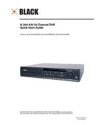
H.264 4/8/16-Channel DVR User Manual - Digiop
H.264 4/8/16-Channel DVR User Manual - Digiop
H.264 4/8/16-Channel DVR User Manual - Digiop

Create successful ePaper yourself
Turn your PDF publications into a flip-book with our unique Google optimized e-Paper software.
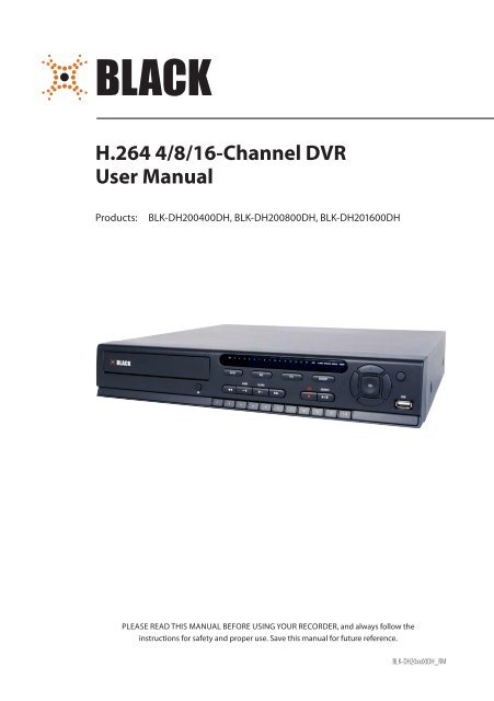
<strong>H.264</strong> 4/8/<strong>16</strong>-<strong>Channel</strong> <strong>DVR</strong><strong>User</strong> <strong>Manual</strong>Products:BLK-DH200400DH, BLK-DH200800DH, BLK-DH20<strong>16</strong>00DHPLEASE READ THIS MANUAL BEFORE USING YOUR RECORDER, and always follow theinstructions for safety and proper use. Save this manual for future reference.BLK-DH20xx00DH_RM
CAUTIONOperate this system only in environments where the temperature and humidity is within the recommended range.Operation in temperatures or at humidity levels outside the recommended range may cause electric shock and shorten thelife of the product. Refer to the specifications for each system component for more information.LEGAL NOTICEDIGIOP products are designed to meet safety and performance standards with the use of specific DIGIOPauthorized accessories. DIGIOP disclaims liability associated with the use of non-DIGIOP authorized accessories.The recording, transmission, or broadcast of any person’s voice without their consent or a court order is strictlyprohibited by law.DIGIOP makes no representations concerning the legality of certain product applications such as the making,transmission, or recording of video and/or audio signals of others without their knowledge and/or consent. Weencourage you to check and comply with all applicable local, state, and federal laws and regulations beforeengaging in any form of surveillance or any transmission of radio frequencies.Microsoft, Windows, Windows Media, and Internet Explorer are either registered trademarks or trademarks of MicrosoftCorporation in the United States and/or other countries. Android is a trademark of Google Inc. Use of this trademarkis subject to Google Permissions. Apple, iPhone, iPod touch, and iPad are registered trademarks of Apple Inc. Intel and Pentiumare trademarks of Intel Corporation in the U.S. and/or other countries.Other trademarks and trade names may be used in this document to refer to either the entities claiming the marksand names or their products. DIGIOP, Inc. disclaims any proprietary interest in trademarks and trade names otherthan its own.No part of this document may be reproduced or distributed in any form or by any means without the express writtenpermission of DIGIOP, Inc.© 2012 by DIGIOP, Inc. All Rights Reserved.3850 Priority Way South Drive, Suite 200, Indianapolis, IN 46240For Sales and Support, contact your distributor.iiwww.digiop.com
Table of ContentsSECTION 1 Introduction . . . . . . . . . . . . . . . . . . . . . . . . . . . . . . . . . . . . . . . . . . . . . . . . . . . . . . . . . . . . . . . . . . . . . . . 1SECTION 2 Hardware Overview . . . . . . . . . . . . . . . . . . . . . . . . . . . . . . . . . . . . . . . . . . . . . . . . . . . . . . . . . . . . . . . . . 22.1 Front panel . . . . . . . . . . . . . . . . . . . . . . . . . . . . . . . . . . . . . . . . . . . . . . . . . . . . . . . . . . . . . . . . . . . . . . . . .22.2 Back panel . . . . . . . . . . . . . . . . . . . . . . . . . . . . . . . . . . . . . . . . . . . . . . . . . . . . . . . . . . . . . . . . . . . . . . . . . .42.2.1 BLK-DH200400DH . . . . . . . . . . . . . . . . . . . . . . . . . . . . . . . . . . . . . . . . . . . . . . . . . . . . . . . . . . . . . . .42.2.2 BLK-DH200800DH . . . . . . . . . . . . . . . . . . . . . . . . . . . . . . . . . . . . . . . . . . . . . . . . . . . . . . . . . . . . . . .52.2.3 BLK-DH20<strong>16</strong>00DH . . . . . . . . . . . . . . . . . . . . . . . . . . . . . . . . . . . . . . . . . . . . . . . . . . . . . . . . . . . . . . .62.2.4 RS485, sensor and alarm termination block . . . . . . . . . . . . . . . . . . . . . . . . . . . . . . . . . . . . . . . . . .72.3 Remote Control . . . . . . . . . . . . . . . . . . . . . . . . . . . . . . . . . . . . . . . . . . . . . . . . . . . . . . . . . . . . . . . . . . . . . .8SECTION 3 System Setup . . . . . . . . . . . . . . . . . . . . . . . . . . . . . . . . . . . . . . . . . . . . . . . . . . . . . . . . . . . . . . . . . . . . . . . 93.1 Starting the system for the first time . . . . . . . . . . . . . . . . . . . . . . . . . . . . . . . . . . . . . . . . . . . . . . . . . . . .93.1.1 Entering the SETUP menu . . . . . . . . . . . . . . . . . . . . . . . . . . . . . . . . . . . . . . . . . . . . . . . . . . . . . . . .103.2 DISPLAY menu . . . . . . . . . . . . . . . . . . . . . . . . . . . . . . . . . . . . . . . . . . . . . . . . . . . . . . . . . . . . . . . . . . . . . .123.3 RECORD menu . . . . . . . . . . . . . . . . . . . . . . . . . . . . . . . . . . . . . . . . . . . . . . . . . . . . . . . . . . . . . . . . . . . . . .133.3.1 Recording Schedules . . . . . . . . . . . . . . . . . . . . . . . . . . . . . . . . . . . . . . . . . . . . . . . . . . . . . . . . . . . .143.4 DEVICE menu . . . . . . . . . . . . . . . . . . . . . . . . . . . . . . . . . . . . . . . . . . . . . . . . . . . . . . . . . . . . . . . . . . . . . . .<strong>16</strong>3.5 STORAGE menu . . . . . . . . . . . . . . . . . . . . . . . . . . . . . . . . . . . . . . . . . . . . . . . . . . . . . . . . . . . . . . . . . . . . .193.6 SYSTEM menu . . . . . . . . . . . . . . . . . . . . . . . . . . . . . . . . . . . . . . . . . . . . . . . . . . . . . . . . . . . . . . . . . . . . . .213.7 SECURITY menu. . . . . . . . . . . . . . . . . . . . . . . . . . . . . . . . . . . . . . . . . . . . . . . . . . . . . . . . . . . . . . . . . . . . .233.8 NETWORK menu . . . . . . . . . . . . . . . . . . . . . . . . . . . . . . . . . . . . . . . . . . . . . . . . . . . . . . . . . . . . . . . . . . . .253.8.1 Network ports . . . . . . . . . . . . . . . . . . . . . . . . . . . . . . . . . . . . . . . . . . . . . . . . . . . . . . . . . . . . . . . . .273.9 CONFIG menu . . . . . . . . . . . . . . . . . . . . . . . . . . . . . . . . . . . . . . . . . . . . . . . . . . . . . . . . . . . . . . . . . . . . . .28SECTION 4 Live, Search, and Playback . . . . . . . . . . . . . . . . . . . . . . . . . . . . . . . . . . . . . . . . . . . . . . . . . . . . . . . . . . . 304.1 SEARCH menu . . . . . . . . . . . . . . . . . . . . . . . . . . . . . . . . . . . . . . . . . . . . . . . . . . . . . . . . . . . . . . . . . . . . . .324.1.1 TIME-LINE search . . . . . . . . . . . . . . . . . . . . . . . . . . . . . . . . . . . . . . . . . . . . . . . . . . . . . . . . . . . . . . .324.1.2 EVENT search . . . . . . . . . . . . . . . . . . . . . . . . . . . . . . . . . . . . . . . . . . . . . . . . . . . . . . . . . . . . . . . . . .334.1.3 GO TO FIRST TIME search . . . . . . . . . . . . . . . . . . . . . . . . . . . . . . . . . . . . . . . . . . . . . . . . . . . . . . . . .344.1.4 GO TO LAST TIME search. . . . . . . . . . . . . . . . . . . . . . . . . . . . . . . . . . . . . . . . . . . . . . . . . . . . . . . . . .344.1.5 GO TO SPECIFIC TIME search . . . . . . . . . . . . . . . . . . . . . . . . . . . . . . . . . . . . . . . . . . . . . . . . . . . . . .344.2 ARCHIVE search . . . . . . . . . . . . . . . . . . . . . . . . . . . . . . . . . . . . . . . . . . . . . . . . . . . . . . . . . . . . . . . . . . . . .354.3 PLAY mode . . . . . . . . . . . . . . . . . . . . . . . . . . . . . . . . . . . . . . . . . . . . . . . . . . . . . . . . . . . . . . . . . . . . . . . . .364.4 Backup video clip . . . . . . . . . . . . . . . . . . . . . . . . . . . . . . . . . . . . . . . . . . . . . . . . . . . . . . . . . . . . . . . . . . .37SECTION 5 PTZ Control . . . . . . . . . . . . . . . . . . . . . . . . . . . . . . . . . . . . . . . . . . . . . . . . . . . . . . . . . . . . . . . . . . . . . . . . 39<strong>H.264</strong> <strong>DVR</strong> <strong>User</strong> <strong>Manual</strong>iii
TABLE OF CONTENTSSECTION 6 Backup . . . . . . . . . . . . . . . . . . . . . . . . . . . . . . . . . . . . . . . . . . . . . . . . . . . . . . . . . . . . . . . . . . . . . . . . . . . 406.1 Still image BACKUP onto USB flash drive . . . . . . . . . . . . . . . . . . . . . . . . . . . . . . . . . . . . . . . . . . . . . . . .406.2 Video BACKUP . . . . . . . . . . . . . . . . . . . . . . . . . . . . . . . . . . . . . . . . . . . . . . . . . . . . . . . . . . . . . . . . . . . . . .406.3 BACKUP still images or video from the ARCHIVE list . . . . . . . . . . . . . . . . . . . . . . . . . . . . . . . . . . . . . .4<strong>16</strong>.4 Playing backed up video clips . . . . . . . . . . . . . . . . . . . . . . . . . . . . . . . . . . . . . . . . . . . . . . . . . . . . . . . . .42SECTION 7 Remote Client Software . . . . . . . . . . . . . . . . . . . . . . . . . . . . . . . . . . . . . . . . . . . . . . . . . . . . . . . . . . . . . 437.1 PC Requirements . . . . . . . . . . . . . . . . . . . . . . . . . . . . . . . . . . . . . . . . . . . . . . . . . . . . . . . . . . . . . . . . . . . .437.2 Installing the Remote Client . . . . . . . . . . . . . . . . . . . . . . . . . . . . . . . . . . . . . . . . . . . . . . . . . . . . . . . . . .437.3 Remote Client initial display . . . . . . . . . . . . . . . . . . . . . . . . . . . . . . . . . . . . . . . . . . . . . . . . . . . . . . . . . .447.4 Setup . . . . . . . . . . . . . . . . . . . . . . . . . . . . . . . . . . . . . . . . . . . . . . . . . . . . . . . . . . . . . . . . . . . . . . . . . . . . .467.4.1 General Setup . . . . . . . . . . . . . . . . . . . . . . . . . . . . . . . . . . . . . . . . . . . . . . . . . . . . . . . . . . . . . . . . . .467.4.2 Site Setup . . . . . . . . . . . . . . . . . . . . . . . . . . . . . . . . . . . . . . . . . . . . . . . . . . . . . . . . . . . . . . . . . . . . .477.4.3 Event Setup . . . . . . . . . . . . . . . . . . . . . . . . . . . . . . . . . . . . . . . . . . . . . . . . . . . . . . . . . . . . . . . . . . . .487.4.4 Event Search Setup . . . . . . . . . . . . . . . . . . . . . . . . . . . . . . . . . . . . . . . . . . . . . . . . . . . . . . . . . . . . .497.4.5 Record Setup . . . . . . . . . . . . . . . . . . . . . . . . . . . . . . . . . . . . . . . . . . . . . . . . . . . . . . . . . . . . . . . . . .507.4.6 Record Disk Setup . . . . . . . . . . . . . . . . . . . . . . . . . . . . . . . . . . . . . . . . . . . . . . . . . . . . . . . . . . . . . .507.4.7 Display Setup . . . . . . . . . . . . . . . . . . . . . . . . . . . . . . . . . . . . . . . . . . . . . . . . . . . . . . . . . . . . . . . . . .517.4.8 Language Setup . . . . . . . . . . . . . . . . . . . . . . . . . . . . . . . . . . . . . . . . . . . . . . . . . . . . . . . . . . . . . . . .517.5 Connecting to a <strong>DVR</strong> . . . . . . . . . . . . . . . . . . . . . . . . . . . . . . . . . . . . . . . . . . . . . . . . . . . . . . . . . . . . . . . . .517.5.1 Bidirectional Audio . . . . . . . . . . . . . . . . . . . . . . . . . . . . . . . . . . . . . . . . . . . . . . . . . . . . . . . . . . . . .527.6 Remote Search mode and functions . . . . . . . . . . . . . . . . . . . . . . . . . . . . . . . . . . . . . . . . . . . . . . . . . . .527.6.1 Searching for and playing video recorded by the <strong>DVR</strong> . . . . . . . . . . . . . . . . . . . . . . . . . . . . . . . .547.6.2 Backing up video from the <strong>DVR</strong> on the Remote Client PC . . . . . . . . . . . . . . . . . . . . . . . . . . . . . .547.6.3 Image capture . . . . . . . . . . . . . . . . . . . . . . . . . . . . . . . . . . . . . . . . . . . . . . . . . . . . . . . . . . . . . . . . .57SECTION 8 Multi Client Software . . . . . . . . . . . . . . . . . . . . . . . . . . . . . . . . . . . . . . . . . . . . . . . . . . . . . . . . . . . . . . 588.1 PC Requirements . . . . . . . . . . . . . . . . . . . . . . . . . . . . . . . . . . . . . . . . . . . . . . . . . . . . . . . . . . . . . . . . . . . .588.2 Installing the Multi Client . . . . . . . . . . . . . . . . . . . . . . . . . . . . . . . . . . . . . . . . . . . . . . . . . . . . . . . . . . . .588.3 Multi Client initial display . . . . . . . . . . . . . . . . . . . . . . . . . . . . . . . . . . . . . . . . . . . . . . . . . . . . . . . . . . . .598.3.1 Using Net Finder . . . . . . . . . . . . . . . . . . . . . . . . . . . . . . . . . . . . . . . . . . . . . . . . . . . . . . . . . . . . . . . .618.3.2 Event List . . . . . . . . . . . . . . . . . . . . . . . . . . . . . . . . . . . . . . . . . . . . . . . . . . . . . . . . . . . . . . . . . . . . . .628.4 Setup . . . . . . . . . . . . . . . . . . . . . . . . . . . . . . . . . . . . . . . . . . . . . . . . . . . . . . . . . . . . . . . . . . . . . . . . . . . . .638.4.1 General Setup . . . . . . . . . . . . . . . . . . . . . . . . . . . . . . . . . . . . . . . . . . . . . . . . . . . . . . . . . . . . . . . . . .638.4.2 Event Setup . . . . . . . . . . . . . . . . . . . . . . . . . . . . . . . . . . . . . . . . . . . . . . . . . . . . . . . . . . . . . . . . . . . .638.4.3 Event Search Setup . . . . . . . . . . . . . . . . . . . . . . . . . . . . . . . . . . . . . . . . . . . . . . . . . . . . . . . . . . . . .648.4.4 Record Setup . . . . . . . . . . . . . . . . . . . . . . . . . . . . . . . . . . . . . . . . . . . . . . . . . . . . . . . . . . . . . . . . . .65ivwww.digiop.com
TABLE OF CONTENTS8.4.5 Record Disk Setup . . . . . . . . . . . . . . . . . . . . . . . . . . . . . . . . . . . . . . . . . . . . . . . . . . . . . . . . . . . . . .668.4.6 Display Setup . . . . . . . . . . . . . . . . . . . . . . . . . . . . . . . . . . . . . . . . . . . . . . . . . . . . . . . . . . . . . . . . . .668.4.7 About Setup . . . . . . . . . . . . . . . . . . . . . . . . . . . . . . . . . . . . . . . . . . . . . . . . . . . . . . . . . . . . . . . . . . .678.5 Connecting to a <strong>DVR</strong> . . . . . . . . . . . . . . . . . . . . . . . . . . . . . . . . . . . . . . . . . . . . . . . . . . . . . . . . . . . . . . . . .678.5.1 Bidirectional Audio . . . . . . . . . . . . . . . . . . . . . . . . . . . . . . . . . . . . . . . . . . . . . . . . . . . . . . . . . . . . .698.5.2 Capture . . . . . . . . . . . . . . . . . . . . . . . . . . . . . . . . . . . . . . . . . . . . . . . . . . . . . . . . . . . . . . . . . . . . . . .698.5.3 Record . . . . . . . . . . . . . . . . . . . . . . . . . . . . . . . . . . . . . . . . . . . . . . . . . . . . . . . . . . . . . . . . . . . . . . . .708.6 Remote playback and backup . . . . . . . . . . . . . . . . . . . . . . . . . . . . . . . . . . . . . . . . . . . . . . . . . . . . . . . . .708.6.1 Remote playback . . . . . . . . . . . . . . . . . . . . . . . . . . . . . . . . . . . . . . . . . . . . . . . . . . . . . . . . . . . . . . .708.6.2 Backing up video from the <strong>DVR</strong> on the Multi Client PC . . . . . . . . . . . . . . . . . . . . . . . . . . . . . . . .728.7 Local playback . . . . . . . . . . . . . . . . . . . . . . . . . . . . . . . . . . . . . . . . . . . . . . . . . . . . . . . . . . . . . . . . . . . . . .738.7.1 AVI backup during playback . . . . . . . . . . . . . . . . . . . . . . . . . . . . . . . . . . . . . . . . . . . . . . . . . . . . .75SECTION 9 Web Client . . . . . . . . . . . . . . . . . . . . . . . . . . . . . . . . . . . . . . . . . . . . . . . . . . . . . . . . . . . . . . . . . . . . . . . . 779.1 Connecting to the <strong>DVR</strong> with IE . . . . . . . . . . . . . . . . . . . . . . . . . . . . . . . . . . . . . . . . . . . . . . . . . . . . . . . .779.2 Setup . . . . . . . . . . . . . . . . . . . . . . . . . . . . . . . . . . . . . . . . . . . . . . . . . . . . . . . . . . . . . . . . . . . . . . . . . . . . .829.2.1 Setup DISPLAY . . . . . . . . . . . . . . . . . . . . . . . . . . . . . . . . . . . . . . . . . . . . . . . . . . . . . . . . . . . . . . . . .839.2.2 Setup RECORD. . . . . . . . . . . . . . . . . . . . . . . . . . . . . . . . . . . . . . . . . . . . . . . . . . . . . . . . . . . . . . . . . .839.2.3 Setup DEVICE . . . . . . . . . . . . . . . . . . . . . . . . . . . . . . . . . . . . . . . . . . . . . . . . . . . . . . . . . . . . . . . . . .849.2.4 Setup STORAGE . . . . . . . . . . . . . . . . . . . . . . . . . . . . . . . . . . . . . . . . . . . . . . . . . . . . . . . . . . . . . . . . .859.2.5 Setup SYSTEM . . . . . . . . . . . . . . . . . . . . . . . . . . . . . . . . . . . . . . . . . . . . . . . . . . . . . . . . . . . . . . . . . .869.2.6 Setup SECURITY . . . . . . . . . . . . . . . . . . . . . . . . . . . . . . . . . . . . . . . . . . . . . . . . . . . . . . . . . . . . . . . .869.2.7 Setup NETWORK . . . . . . . . . . . . . . . . . . . . . . . . . . . . . . . . . . . . . . . . . . . . . . . . . . . . . . . . . . . . . . . .879.2.8 Setup UPGRADE . . . . . . . . . . . . . . . . . . . . . . . . . . . . . . . . . . . . . . . . . . . . . . . . . . . . . . . . . . . . . . . .889.2.9 Setup INFORMATION . . . . . . . . . . . . . . . . . . . . . . . . . . . . . . . . . . . . . . . . . . . . . . . . . . . . . . . . . . . .889.3 <strong>DVR</strong> Search. . . . . . . . . . . . . . . . . . . . . . . . . . . . . . . . . . . . . . . . . . . . . . . . . . . . . . . . . . . . . . . . . . . . . . . . .889.3.1 Playing recorded video . . . . . . . . . . . . . . . . . . . . . . . . . . . . . . . . . . . . . . . . . . . . . . . . . . . . . . . . . .909.4 Backup recorded video . . . . . . . . . . . . . . . . . . . . . . . . . . . . . . . . . . . . . . . . . . . . . . . . . . . . . . . . . . . . . . .919.4.1 Capture . . . . . . . . . . . . . . . . . . . . . . . . . . . . . . . . . . . . . . . . . . . . . . . . . . . . . . . . . . . . . . . . . . . . . . .91SECTION 10 Specifications . . . . . . . . . . . . . . . . . . . . . . . . . . . . . . . . . . . . . . . . . . . . . . . . . . . . . . . . . . . . . . . . . . . . . 93APPENDIX A HDD Replacement . . . . . . . . . . . . . . . . . . . . . . . . . . . . . . . . . . . . . . . . . . . . . . . . . . . . . . . . . . . . . . . . . . 95APPENDIX B Estimated Storage Capacity. . . . . . . . . . . . . . . . . . . . . . . . . . . . . . . . . . . . . . . . . . . . . . . . . . . . . . . . . . 99APPENDIX C Device Log . . . . . . . . . . . . . . . . . . . . . . . . . . . . . . . . . . . . . . . . . . . . . . . . . . . . . . . . . . . . . . . . . . . . . . . 100APPENDIX D <strong>DVR</strong> Setup Menu Components . . . . . . . . . . . . . . . . . . . . . . . . . . . . . . . . . . . . . . . . . . . . . . . . . . . . . . 101<strong>H.264</strong> <strong>DVR</strong> <strong>User</strong> <strong>Manual</strong>v
viwww.digiop.com
SECTION 1: INTRODUCTIONSECTION 1IntroductionFeatures• <strong>H.264</strong> Video Compression• Reliable File System• Live and Event Pop-up• VGA display interface (1280 x 1024)• 4 <strong>Channel</strong> Audio Recording• Bidirectional Audio• Individual <strong>Channel</strong> Operation• Motion Detection• Automatic Video Input and Video Loss Detection• Covert Camera Operation Provides Enhanced Security• Built-In PTZ Camera Control• <strong>User</strong> friendly operator interface• Record scheduler• Software upgradable• Backup via USB flash drive, Network or DVD-R/W• Exclusive file format backup• AVI backup• Network Access via Web Client (embedded browser-based client), UMS Client (for monitoring a single <strong>DVR</strong>), Multi Client (formonitoring multiple <strong>DVR</strong>s concurrently), and smartphone apps for Apple® iPhone® and Android.Your <strong>DVR</strong> includes:• <strong>DVR</strong> with DVD-R/W drive and hard disk drive (HDD)• Software CD containing the UMS Client, Multi Client, and the <strong>DVR</strong> user manual (this document)• Remote Control• Battery 1.5V (2 x AAA)• Power Adaptor (12VDC, 5A) and cable• Mouse• Quick Start Guide document<strong>H.264</strong> <strong>DVR</strong> <strong>User</strong> <strong>Manual</strong>1
SECTION 2: HARDWARE OVERVIEWSECTION 2Hardware Overview2.1 Front panel4/8/<strong>16</strong> <strong>Channel</strong> <strong>DVR</strong> Front PanelTable 1. Front Panel LED IndicatorsNo. Name DescriptionA CH1~<strong>16</strong> Indicates that the channel is being recorded.B HDD Indicates that the system is accessing the hard disk.C ALARM Indicates when a sensor is triggered or motion is detected.D NETWORK Indicates that a network client is connected.E BACKUP Indicates that a USB or DVD-R/W storage device is storing images or video.F POWER Indicates that the system is switched on.Table 2. Front Panel ButtonsNo. Name Description1<strong>Channel</strong> keys. For channel 10, press the 0 key. For channel 11, press the +10 and 1 key. For channel <strong>16</strong>, press the +10and 6 key.2 Press to rewind the video in playback mode.AUDIO3 .. Press to select audio mode such as SINGLE (highlighted channel), MIX (combine all channels), or MUTE (all channels).2 www.digiop.com
SECTION 2: HARDWARE OVERVIEWNo. Name DescriptionAUDIO4 .. Jump/step backward. In playback mode, the playback position moves 60 seconds backward.5 Press to fast forward the footage in playback mode.ALARM6 ..Press to enable/disable ALARM operation.ALARM7 ..Jump/Step forward. In playback mode, the playback position moves 60 seconds forward.8RECPress to start or stop manual recording.SEARCH9 / llPress to open the SEARCH menu in live display mode.SEARCH10 / llPress to play/pause the recording in playback mode.11SETUPPress to enter SETUP menu.12SEQEnable/disable the automatic sequence display of channels in full screen, quad-split, and 9-split display mode.13PTZPress to control Pan/Tilt/Zoom operations.14BACKUPPress to capture live or playback mode video in JPEG format.15 t (LEFT) Press to move left or to change the values in Setup mode. When entering a password, it inserts a 4.<strong>16</strong> p (UP) Press to move up the menu in Setup mode. When entering a password, it inserts a 1.17 u (RIGHT) Press to move right or to change the values in Setup mode. When entering a password, it inserts a 2.18 q (DOWN) Press to move down the menu in Setup mode. When entering a password, it inserts a 3.19 SELPress to select desired menu item or to store the setup value.20ESCPress for temporary storage of the changed value or to return to the previous menu screen.21 USB PortUse with a USB flash drive to archive still images and videos, and upgrade firmware, or use to connect a USB mouse tothe <strong>DVR</strong>.22To open and close the insert tray, press the button23 DVD Drive To save video, insert a CD-R/DVD-R<strong>H.264</strong> <strong>DVR</strong> <strong>User</strong> <strong>Manual</strong>3
SECTION 2: HARDWARE OVERVIEW2.2 Back panel2.2.1 BLK-DH200400DH4-<strong>Channel</strong> <strong>DVR</strong> Rear PanelTable 3. BLK-DH200400DH Rear Panel ConnectorsNo. Name Description1 Fan Airflow outlet23VIDEO INVIDEO OUTAUDIO INAUDIO OUT4 HDMI HDMI video out.4 BNC connectors for composite video inputCVBS1, CVBS2 composite video output4 RCA connectors for audio input1 RCA connector for audio output5 RS-232 interface Used for testing only. .6 VGA Connector for a VGA monitor.7 eSATA port Connector for external storage8 ETHERNET RJ-45 connector for LAN connection.9 USB Use with a USB flash drive to archive still images and videos, and upgrade firmware, or use to connect a USB mouse to the <strong>DVR</strong>10RS-485, sensorand alarmterminationsSee description below.11 POWER SOCKET Connect DC12V 5A power adaptor4 www.digiop.com
SECTION 2: HARDWARE OVERVIEW2.2.3 BLK-DH20<strong>16</strong>00DH<strong>16</strong>-<strong>Channel</strong> <strong>DVR</strong> Rear PanelTable 5. BLK-DH20<strong>16</strong>00DH Rear Panel ConnectorsNo. Name Description1 Fan Airflow outlet23VIDEO INVIDEO OUTAUDIO INAUDIO OUT4 HDMI HDMI video out.4 BNC connectors for composite video inputCVBS1, CVBS2 composite video output4 RCA connectors for audio input1 RCA connector for audio output5 RS-232 interface Used for testing only. .6 VGA Connector for a VGA monitor.7 eSATA port Connector for external storage8 ETHERNET RJ-45 connector for LAN connection.9 USB Use with a USB flash drive to archive still images and videos, and upgrade firmware, or use to connect a USB mouse to the <strong>DVR</strong>10RS-485, sensorand alarmterminationsSee description below.11 POWER SOCKET Connect DC12V 5A power adaptor6 www.digiop.com
SECTION 2: HARDWARE OVERVIEW2.3 Remote ControlTypical Remote ControlNOTEThe remote control provided with your <strong>DVR</strong> may appear different from the one shown above. However, the buttons function asdescribed in the table below.Table 6. Remote Control Button FunctionsNo. Name Function1 ID When a remote control ID number is setup in <strong>DVR</strong>, press this button before the number.2 REC To start and stop manual recording.3 0 .. 9 To select channel (1, 2, 3, ..) or to enter a <strong>DVR</strong> ID number.4 F/REW5 F/ADVDuring Playback – To move the playback position 60 seconds back.During Pause – To move the playback position 1 frame back.During Playback – To move the playback position 60 seconds forward.During Pause – To move the playback position moves 1 frame forward.6 REW To rewind the recording. Press again to increase the rewind speed.7 PLAY/PAUSE To play or to pause the recording in playback mode.8 FF To fast forward the recording. Press again to increase the fast forward speed.9DirectionButtonsPress to move to menu items or select a channel.10 SETUP To open the SETUP menu.11 SEARCH To go to the SEARCH menu.12 ESCDuring setup – To return to the previous menu screen.During playback – To exit playback modeSystem lock – To lock a system when pressing ESC button for 5 seconds.System unlock – To unlock a system when pressing ESC button for 5 seconds.13 BACKUP To start a backup operations in live or playback mode.14 SEQ To start auto sequencing the screen in full screen mode. (Toggle)8 www.digiop.com
SECTION 3: SYSTEM SETUPSECTION 3System Setup3.1 Starting the system for the first timeWhen booting the system for the first time, the following messages appear. After the initialization sequence completes, select yourpreferred language and set the date and time.When the Set date and time window opens, use the dropdown lists to show the correct date and time, then click Finish. Thedate and time setting is used to timestamp recordings.<strong>H.264</strong> <strong>DVR</strong> <strong>User</strong> <strong>Manual</strong>9
SECTION 3: SYSTEM SETUPNOTEFor improved security, DIGIOP recommends that you change the password. You can select a new password through the SECURITYtab in the SETUP menu.Open a menu by clicking the tab. To close the window, click Cancel. To save changes made to the menus before closing thewindow, click OK.For a summary of the elements in each SETUP submenu (tab), refer to Appendix C.Navigating the menusYou can navigate through the menu system, change option values, and click buttons with the mouse. Entry fields usuallyhave drop-down menus you can open to select preset parameter values. Other parameters fields open submenus orkeyboards you can use to enter names and other values. You can also navigate through the menu items using the directionbutton, p, q, t, or u and change option values with the SEL button. Always select (or click) OK to save new settingsand close the SETUP menus. Press the ESC button at any time to exit the SETUP menus.NOTEIn the following descriptions of the SETUP menus, the instructions for navigating the system includes use of the front panelbuttons only. Using a mouse for menu navigation and setup of system options can be easier and faster.<strong>H.264</strong> <strong>DVR</strong> <strong>User</strong> <strong>Manual</strong>11
SECTION 3: SYSTEM SETUP3.2 DISPLAY menuOpening the SETUP menu, or clicking the DISPLAY tab, opens the DISPLAY menu.Open SubmenuOpen Drop-down ListDrag to adjustTable 7. DISPLAY menu optionsItemOSDDescriptionEnable/disable the on-screen display.OSD CONTRAST Set the visibility level of the OSD. (0 ~ 100)SEQUENCESEQ-DWELL TIMECHANNELEnable/disable sequential display of video in full screen mode.Set the dwell time of each quad-split or 9-channel display in sequential display mode. (3 - 60 seconds)In the channel submenu, you can tune the display settings for all cameras at once, or setup each camera individually. Click thechannel drop-down list to select the channel, then use the click the submenu buttons to NAME the channel and set the COVERTproperty (enable/disable live display mode). Drag the marker on the image adjustment bars to perfect the image.BRIGHTNESS: Change the brightness value of the selected channel. (0 ~ 100)CONTRAST: Change the contrast value of the selected channel. (0 ~ 100)HUE: Change the hue value of the selected channel. (0 ~ 100)SATURATION: Change the saturation value of the selected channel. (0 ~ 100)Click OK to save the settings and close the window.12 www.digiop.com
SECTION 3: SYSTEM SETUPItemVIDEO OUTPUT (VGA)VIDEO OUTPUT(CVBS UNDER SCAN)DescriptionClick the submenu button to open a list of monitor resolutions, then click the resolution you prefer. Click OK.TBS.3.3 RECORD menuClicking the RECORD tab opens the RECORD menu.<strong>H.264</strong> <strong>DVR</strong> <strong>User</strong> <strong>Manual</strong>13
SECTION 3: SYSTEM SETUPTable 8. Menu Items in Recording Mode SetupMenu ItemCHANNELDescriptionIn the Record <strong>Channel</strong> submenu, you can set the recording modes for all cameras at once, or setup each camera individually.Click the submenu button to open the setup window. Click a field to highlight it, click the down arrow in the field, then select theoption you want from the drop-down menu. Click OK to save the settings and close the window.RESOLUTION Select either CIF, Half D1, or D1.FRAME RATEQUALITYRECORDINGSet the frame rate for the specified channel (1 ~ 30 fps). The sum of the frame rates from each channel cannot exceed the maximumframe rates for a specific recording resolution. See the Specifications section for the maximum video frame o f your recorder.Select the recording quality for the specified channel (Level 1 (low) to Level 5 (high)).Assign the recording mode for each channel. Options are: Disable, Continuous, Motion,Sensor,Schedule.PRE RECORD Enable/disable pre-event recording. Options are OFF, 15 SEC, 30 SEC, 1 MIN, 3 MIN, 20 MIN. .POST EVENT RECORDSENSOR RECORDINGAUDIOSCHEDULESet the post event recording time duration for the specified channel. (10 ~ 60 seconds)Enable setting up to 4 sensors for the specified channel.Enable/disable audio recording for channel 1 .. 4 only.Click the submenu icon to open the recording schedule setup window. To configure this feature, see the sub-section RecordingSchedules below.3.3.1 Recording SchedulesTo setup a weekly recording schedule, click the SCHEDULE submenu bar in the RECORD menu. A recording mode (NONE,CONTINUOUS, MOTION, or SENSOR) can be applied to any hour of the week for each camera.14 www.digiop.com
SECTION 3: SYSTEM SETUP[CHANNEL]: Select the channel for the schedule you are setting.[MODE]: Click the recording mode (NONE, CONTINUOUS, MOTION, or SENSOR) to apply to the schedule, then drag the mouse cursoracross the days and hours in the grid you where you want to use that mode. Timeslots are color coded for the record mode appliedto them: CONTINUOUS - green, MOTION - yellow, and SENSOR - red, NONE - white.[COPY SCHEDULE]: To copy the schedule you setup to other cameras, click the camera channel number(s), then click COPY. You canalso use the front panel buttons, p, q, t, u, and SEL buttons to perform these selections.Click OK to save your settings, or press ESC to return to the RECORD menu.<strong>H.264</strong> <strong>DVR</strong> <strong>User</strong> <strong>Manual</strong>15
SECTION 3: SYSTEM SETUPTable 9. Menu Items in Device Setup ScreenItemALARM OUTDescriptionSet the sensor, motion, and video loss for each alarm.ALARM OUT: 1 only.SENSOR IN: Enable alarm out by sensor (up to 4 inputs).MOTION ON: Enable alarm out by camera motion (up to 4 cameras can be monitored).VIDEO LOSS ON: Enable alarm out by camera video loss (up to 4 cameras can be monitored).ALARM DURATION: Set the alarm dwell time. (5 ~ 60 seconds or infinite (continuous)).ERROR ALARM: Set the error type for the alarm activation. (OFF, ALL, HDD ERROR, VIDEO LOSS).CONTROLLER AND PTZTo control the PTZ functions of the camera, connect the PTZ controller to the RS-485 port on the back of the chassis withCAT 5 (or equivalent) cable. Setup the CONTROLLER AND PTZ submenu SPEED and ID to match the controller and cameraconfiguration.CHANNEL: <strong>Channel</strong> connected to a PTZ deviceNAME: Protocol typeSPEED: Baud rate: 19200, 14400, 9600, 4800, 2400ID: 0 ~ 63<strong>H.264</strong> <strong>DVR</strong> <strong>User</strong> <strong>Manual</strong>17
SECTION 3: SYSTEM SETUPItemSPOT OUTDescriptionEnable/disable display of the channel when an event is active.SPOT ON EVENT: Enable/disable display of the channel when an event is active..SPOT EVENT DWELL TIME: Set the dwell time for the event activated channel (1 - 10 sec).SEQUENCE: Enable/disable sequential display of spot channel(s) in full screen. If ON is selected, the spot channel isdisplayed.SEQUENCE-DWELL TIME: Set the dwell time for the spot channel display (1-10 sec).SPOT CHANNEL: Select a channel for spot monitoring. Press SEL and select channel using the p, q, t, and u buttons,then press SEL.CHANNELMOTION ZONESelect specified channel for motion zone setup.Select either Full Zone or Partial Zone for motion sensing.FULL ZONE: The motion sensor is active on the whole screen. Set the level of sensitivity for MOTION SENSITIVITY.PARTIAL ZONE: Selecting Partial Zone for the channel, then clicking the submenu button, opens a widow containing thecamera image overlaid with a 22 x 15 block areas. You can select motion sensing for the blocks in the areas individuallyby clicking on them, or you can select a larger area by dragging the mouse cursor across a rectangle of blocks. Block areasselected for motion sensing are shaded green. To disable motion sensing on a selected block, click on it.To return to the Device menu, right click on the screen, or press the ESC button on the front panel.MOTION SENSITIVITY Set the motion sensitivity for the specified channel. (1 ~ 9).18 www.digiop.com
SECTION 3: SYSTEM SETUPItemDISK FORMATDISK INFODescriptionSelect YES or NO to format the hard drive (disk). Caution: Formatting the hard drive will erase all information on the disk.Archive all data that you may need before formatting the disk.Click the submenu button to view hard drive informationClick DETAIL to show the performance health of the drives.RECORDING LIMITRECORDING LIMIT DAYSS.M.A.R.T.Enable/disable a recording limit (days).Set the recording limit in days (1- 90 days). If set to 1 day, data older than 24 hours will be removed.Click the submenu button to view hard drive S.M.A.R.T. data for each hard drive.Select the options on the S.M.A.R.T. menu as needed.20 www.digiop.com
SECTION 3: SYSTEM SETUP3.6 SYSTEM menuClicking the SYSTEM tab opens the system menu. Navigate through the menu items using mouse. You can also navigate the menuswith the p, q, t, and u buttons, and press SEL to select options.Table 11. Menu Items in SYSTEM Setup ScreenItem<strong>DVR</strong> IDDescriptionSelect the submenu button to open the virtual keyboard, then click your way to a new name for your <strong>DVR</strong>. The <strong>DVR</strong> ID canhave a most 10 characters.. Click OK when finished.<strong>H.264</strong> <strong>DVR</strong> <strong>User</strong> <strong>Manual</strong>21
SECTION 3: SYSTEM SETUPItemDESCRIPTIONDescriptionClick the DESCRIPTION submenu button to open an information showing a summary of your <strong>DVR</strong>. OPress the SEL button toview system information (hardware version, software version, storage size, IP address, MAC address, and DDNS status). NOTE:This window shows the software version number. Click OK to close the window.LANGUAGEDATE FORMATSET DATE & TIMEOpen the drop-down list to select your preferred menu system language. Several language options are available.Select the date format using the p, q, t, and u buttons. Options include: YYYY/MM/DD, MM/DD/YYYY, DD/MM/YYYY,YYYY-MM-DD, MM-DD-YYYY, DD-MM-YYYY.Click the submenu button to open the DATE & TIME setup window. Click each field and select the current value from the dropdownlist. In the DAYLIGHT SAVINGS list, select OFF, USA, EU (European union) or OTHERS. Click OK to commit the settings.CLIENT ACCESSNTPEnable (ON) or Disable (OFF) remote access through network client software.Click the NTP field and select ON, then click the submenu button to open the NTP setup menu. Use this feature to synchronizethe clocks of computer systems over variable-latency data networks.PRIMARY SNTP SERVER: Use the virtual keyboard to enter the address of the primary NTP time server.SECONDARY SNTP SERVER: Use the virtual keyboard to enter the address of the secondary NTP time server.TIME ZONE: Select the offset from GMT (Greenwich Mean Time).CONNECTON MODE: Select an NTP time server connection mode (INTERVAL/TIME).INTERVAL: Synchronize the clock by hours shown on the connection period option.TIME: Synchronize the clock at the time daily shown on the connection period menu. CONNECTION PERIOD: 1 ~ 24.22 www.digiop.com
SECTION 3: SYSTEM SETUPItemSEND EMAILDescriptionClick the SEND MAIL field and select ON, then click the submenu button to show the setup options.TRANSMISSION MODE: When an alarm is triggered, send an image of only the channel that triggered the alarm.IP NOTIFICATION: Enable/disable sending email when the IP address of your <strong>DVR</strong> is changed.EVENT ALARM: When an alarm is triggered, enable/disable sending email reports of the channel that triggered the alarm.MAIL BY S.M.A.R.T.:MAIL PORT: Port number of the mail server.SECURE OPTION: Select security method: NONE, SSL or TLSMAIL TO: Use the virtual keyboard to enter the email address of the recipient.MAIL SERVER: Use the virtual keyboard to enter the mail server information.ID: Use the virtual keyboard to specify the user ID for the mail server.PASSWORD: Use the virtual keyboard to specify the connection password for the mail server.MAIL FROM: Use the virtual keyboard to specify the email address sent to the destination host.3.7 SECURITY menuClicking the SECURITY tab opens the security menu. Navigate through the menu items using mouse. You can also navigate themenus with the p, q, t, and u buttons, and press SEL to select options.NOTEYou must be a user with Admin permissions to configure the SECURITY menu.<strong>H.264</strong> <strong>DVR</strong> <strong>User</strong> <strong>Manual</strong>23
SECTION 3: SYSTEM SETUPTable 12. Menu Items in PASSWORD Setup ScreenItemUSER AUTHENTICATIONDescriptionClick the <strong>User</strong> Authentication submenu button to open the PASSWORD and PERMISSION menu. Check or uncheck boxes toallow permissions to different users for access to areas of the system.In the PASSWORD CHECK row, check or uncheck the box to select for all users, or check or uncheck the individual settings foreach user. Press ESC to return to the SECURITY menu. Options are defined as:SETUP: Access to the SETUP menusPB: Control video PlaybackPTZ: Control and configure PTZ (Pan/Tilt/Zoom) device settingsR/OFF: Control manual recording (ON/OFF)NETWORK: Change network settings24 www.digiop.com
SECTION 3: SYSTEM SETUPItemUSER PASSWORDDescriptionClick the <strong>User</strong> Password submenu button to open the password setup menu. To change a password, select a user from thedrop-down list, then enter the current, new, and confirm password fields Click OK when finished. The factory default Adminuser password is 1111.PLAYBACK AUTHORITYClick the <strong>User</strong> Playback Authority submenu button to open the setup menu. Check or uncheck boxes to assign playback rights tousers for viewing video clips of cameras channels.NOTEFor improved system security, it is strongly recommended that you change the factory default passwords during the initialsetup of your system.3.8 NETWORK menuClicking the NETWORK tab opens the setup menu. Navigate through the menu items using mouse. You can also navigate the menuswith the p, q, t, and u buttons, and press SEL to select options.NOTEYou must be a user with Admin permissions to configure the NETWORK menu.For additional guidelines for determining network settings, refer to the <strong>DVR</strong> Networking Guide provided with your system. Thisguide is also available through your support team.<strong>H.264</strong> <strong>DVR</strong> <strong>User</strong> <strong>Manual</strong>25
SECTION 3: SYSTEM SETUPTable 13. Menu Items in the NETWORK menuItemDescriptionPORT Click the submenu button to open a keypad for entering the port number (default: 5445)WEB PORT Click the submenu button to open a keypad for entering the web sever port number (default: 80)NETWORK TYPEDHCPSTATICSelect a type of network connection. Options are: DHCP or STATIC. NOTE: Depending on the type selected, the options in thenetwork menu will change appropriately.If selected, the <strong>DVR</strong> automatically acquires its network settings from a DHCP server. This address may change without notice.If selected, you must configure the network settings manually. These settings remain in effect until manually changed.IP: Enter the IP address assigned to the <strong>DVR</strong>.GATEWAY: Enter the Gateway IP address assigned for the <strong>DVR</strong>.SUBNET MASK: Enter the Subnet Mask for the subnet where the <strong>DVR</strong> is connected.DNS: Enter the DNS primary and secondary server addresses.26 www.digiop.com
SECTION 3: SYSTEM SETUPItemDDNSDescriptionTo use DDNS, open the drop-down list and select SERVER1, then click the submenu button to the right. Select ddnscenter.comfrom the three DDNS servers. (If you select another DDNS server, the <strong>DVR</strong> cannot connect to the DDNS properly.)DDNS (SERVER1): Select one of the following DDNS servers: in USA, use www.ddnscenter.com, in Korea, use www.okddns.com, or if in the EU, or use www.bestddns.com.DDNS INTERVAL: 5 - 60 minutes.If you select SERVER2 from the drop-down list, you can configure the <strong>DVR</strong> to use a general-purpose DDNS server.NETWORK STREAMClick the submenu button to open network stream setup submenu This menu is used to configure the resolution, frame rate,and quality at which live video from each camera can stream across the network. The total data rate permissible is dependenton the model of your <strong>DVR</strong>. Refer to the Specifications section for more information. CSet the preferred options using the dropdownlists, then select OK.3.8.1 Network portsWhen you connect one or more <strong>DVR</strong>s to a network through an IP sharing device, each <strong>DVR</strong> must be assigned a unique TCP portnumber for access from outside the LAN. Additionally, the IP sharing device must be configured to forward the assigned port to thespecific <strong>DVR</strong>.NOTEThis port number is listed next to the Port menu option in the Network Setup screen. If you access the <strong>DVR</strong> only from within thesame LAN, the TCP port number does not need to be changed.<strong>H.264</strong> <strong>DVR</strong> <strong>User</strong> <strong>Manual</strong>27
SECTION 3: SYSTEM SETUPNetwork access beyond a routerTo access the <strong>DVR</strong> beyond a router (firewall), you must open TCP ports for commands, for live channels, and for storage channels.The default <strong>DVR</strong> port numbers are 5445 and the web port number 80. If this port is not opened properly, you cannot access the <strong>DVR</strong>outside a router.3.9 CONFIG menuClicking the CONFIG tab opens the system configuration menu. Navigate through the menu items using mouse. You can alsonavigate the menus with the p, q, t, and u buttons, and press SEL to select options.Table 14. CONFIG menu itemsItemSAVE SETUP TO A USBDescriptionClick the submenu icon. To save the current system configuration to the USB flash drive, plug the flash drive into the USB port onthe front panel, click OK to confirm the operation, then follow the on-screen prompts to complete the save. NOTE: If the message“CHECK USB” appears, repeat the process until “SAVE SUCCESS” is shown.28 www.digiop.com
SECTION 3: SYSTEM SETUPItemLOAD SETUP FROMA USBDescriptionClick the submenu icon. To upload a saved <strong>DVR</strong> configuration from a USB flash drive, plug the flash drive into the front panel USBport, click OK to confirm the operation, then follow the on-screen prompts to complete the upload.LOAD DEFAULTClick the submenu icon. Select YES to load the system default settings. NOTE: The following items are not reset: language, <strong>DVR</strong> ID,Security <strong>User</strong> Authentication, Security <strong>User</strong> P/W, date format, DLS settings, network settings, HDD overwrite, limit recording, HDDserial number, and HDD ERROR time.LOAD FACTORYDEFAULTClick the submenu icon. Select YES to reset the system to the factory default settings.SOFTWARE UPGRADEClick the submenu icon. Select SCAN to search the USB file for firmware, then follow the on-screen instructions to complete theupload.<strong>H.264</strong> <strong>DVR</strong> <strong>User</strong> <strong>Manual</strong>29
SECTION 4: LIVE, SEARCH, AND PLAYBACKSECTION 4Live, Search, and PlaybackIn the Live screen, video inputs from the cameras are displayed the On-screen display (OSD) features as configured in the DisplaySetup screen. OSD icons that indicate the status of the <strong>DVR</strong> are shown along the bottom of the screen.Table 15. Status Indicator Icons in Live Viewing ScreenIconDescriptionPower On/Off button.Lock/Unlock SETUP button.Setup button. Click this button to open the SETUP menu.Audio button. Click this button to set the audio reception type: audio mute, single audio channel, or 4 audio channels. To set a singleaudio channel, first select a specific channel on the live screen.Search button. Click this button to open the search menu.Backup button. Click this button to perform a backup.PTZ button for control of PTZ cameras. When this button is clicked, a PTZ control window will open.30 www.digiop.com
SECTION 4: LIVE, SEARCH, AND PLAYBACKIconDescriptionSequence button. Click this button to use a sequence function.<strong>Manual</strong> Record button. Click this button to begin recording.Alarm-out function on/off button. When an alarm is in progress, click this button to stop reporting the alarm.Click the split screen icon to change the current split screen mode.Indicates that the lock is set.Indicates that alarm is set. To set the alarm function, press the Alarm button on the front panel.Indicates that the alarm output is activated.Audio mute. To set audio mute, press the Audio button on the front panel.Single audio channel. To set audio single channel for the selected channel only, press the Audio button on the front panel.To mix audio channels, press the Audio button on the left side.Alarm indicator. When an alarm is activated (sensor or motion alarm) in the video channel, this icon will be highlighted bright red.Indicates that a network client is connected to the <strong>DVR</strong>.Indicates that sequencing mode is enabled.The current date and time.Remote control ID display. If a remote ID is not set, the message “A(all)” is displayed.Displays the amount of recording space used on the hard disk from 0-99%.Indicates that HDD is recycled (full and overwriting oldest data with new data).Continuous recording in progress.<strong>Manual</strong> recording in progress. To set <strong>Manual</strong> recording mode, press the Record button on the front panel.Motion alarm recording in progress.Sensor recording in progress.<strong>H.264</strong> <strong>DVR</strong> <strong>User</strong> <strong>Manual</strong>31
SECTION 4: LIVE, SEARCH, AND PLAYBACKOSD menuYou can open the on-screen display menu with the mouse by right-clicking anywhere on the Live screen. Options in the OSD menuare also represented by the icons in the tray at the bottom of the screen.4.1 SEARCH menuTo open the SEARCH menu, press the SEARCH button on the front panel or click the SEARCH icon on the Live screen.Recorded data can be searched in the following ways: TIMELINE, EVENT, GO TO FIRST TIME, GO TO LAST TIME, GO TO SPECIFIC TIME,ARCHIVE, and LOG.4.1.1 TIME-LINE searchThe TIME-LINE search window is used to find stored video by using the time line bar. Select TIME LINE in the SEARCH menu, thenselect NEXT. A calendar window will open.32 www.digiop.com
SECTION 4: LIVE, SEARCH, AND PLAYBACKThe highlighted days in the calendar window indicate that data was recorded at that time. The day selected is highlighted blue.Select the day of interest, then select NEXT.MarkerIn the TIME LINE window, the highlighted bars show the time of day when data was recorded. Drag the marker to the time whenyou want to begin playing a recording, click the channel number of interest, then click NEXT to play the video. To expand thetimeline, click the icon in the upper-right corner between the t and u buttons. To stop the video playback, press the ESC buttonon the front panel.4.1.2 EVENT searchUse EVENT search to quickly find recordings associated with specific events. To open the EVENT search window, select EVENT onthe SEARCH window, then select NEXT. A calendar window will open (see above).The highlighted days in the calendar window indicate that video was recorded at that time. Select the day of interest, then selectNEXT.<strong>H.264</strong> <strong>DVR</strong> <strong>User</strong> <strong>Manual</strong>33
SECTION 4: LIVE, SEARCH, AND PLAYBACKIn the Event list window, click the event of interest, then click NEXT to play the video. Press the ESC button to stop playing the videoand return to the event list window.The submenu button in the upper right corner opens a channel selection window where you can select the specific channel youwant to play. Select the channel, the press the ESC button to return to the event list window.4.1.3 GO TO FIRST TIME searchYou can access from the oldest recorded data on the <strong>DVR</strong> by selecting GO TO FIRST TIME on the SEARCH window. Press the ESC toreturn to the SEARCH window.4.1.4 GO TO LAST TIME searchYou can access from the last minute recorded data on the <strong>DVR</strong> by selecting GO TO LAST TME on the SEARCH window. Press the ESCto return to the SEARCH window.4.1.5 GO TO SPECIFIC TIME searchIn the SEARCH window, select GO TO SPECIFIC TIME, then use the mouse with the drop-down lists or the p, q, t, and ubuttons to enter the starting time of the video you want to play.34 www.digiop.com
SECTION 4: LIVE, SEARCH, AND PLAYBACKIn the archive LOG list, select the file entry with the date and time when the data was backed up, then select DISPLAY. In theARCHIVE IMAGE window, the timestamp of the recorded is shown in the Backup frame. Select the image and MEDIA location, thenclick BACKUP. To close the ARCHIVE IMAGE window, press ESC or click CLOSE.4.3 PLAY modePlaying a recorded event changes the <strong>DVR</strong> mode from SEARCH to PLAY. While in PLAY mode, you can return to the SEARCH screenby pressing the front panel ESC button or clicking the T icon.Playback controls are located at the bottom of the screen.36 www.digiop.com
SECTION 4: LIVE, SEARCH, AND PLAYBACKTimestampMode Play controlsBackup CloseTable <strong>16</strong>. Playback controls (PLAY Mode)IconDescriptionGo to the previous menu screen or search window, or exit from the menu.t tSelect to rewind the recording. Select again to increase the rewind speed.-- t Jump/step backward. The playback position moves 60 seconds back.u / II Select to play or pause a recording.u --Jump/step forward. Playback position moves 60 seconds ahead.u u Select to fast forward the recording. Select again to increase the fast forward speed.-- u- Slow playback.Select to backup video clip..4.4 Backup video clipYou can archive the video clip by clicking the Backup button in Play mode (see the screen above. The system adds all backed-upvideo clips to the Archive search list. The Backup button is located on the play control bar.Timestamp markerBackup buttonPlay motion controlsClose Play mode buttonTo archive the clip:1. Click the Backup button.<strong>H.264</strong> <strong>DVR</strong> <strong>User</strong> <strong>Manual</strong>37
SECTION 4: LIVE, SEARCH, AND PLAYBACK2. Select the device you want to backup (archive) to. All archive devices are listed in the media window.3. Click NEXT.4. In the window that opens, select the duration of the video clip from the drop-down list, then click START.Allow the backup operation to complete before continuing.38 www.digiop.com
SECTION 5: PTZ CONTROLSECTION 5PTZ ControlTo control the PTZ functions of the camera, select Camera PTZ on the OSD menu. Use the p, q, t, and u buttons to select thechannel of the PTZ camera and features you want to control.Table 17. Button functions in PTZ controlItemINITIALIZEPAN / TILTZOOM / FOCUSOSDAUTOSCANPRESETTOURNUMBERDescriptionInitialize the PTZ settings of the selected camera.Select PAN/TILT using the p q t and u button, then and press SEL. Adjust the tilt (UP/DOWN)/pan (LEFT/RIGHT) position using the p, q, t, and u buttons.Select ZOOM/FOCUS using the p, q, t, and u buttons, then press SEL. Adjust the zoom(UP/DOWN)/focus (LEFT/RIGHT) position using the p, q, t, and u buttons.Select OSD to enter the menu. Control keys are Right, Left, UP, Down, Select, Far (REW KEY),and Near (FF KEY). Press the ESC button to return to the previous menu. Press the PTZ buttonto close the OSD menu.Press the right key (u) to start auto scan. Press the left key (t) to stop auto scan.Select PRESET, then press the left key (t). A number input window will appear. Set thenumber (3 digits) using the number key, then press the SEL to confirm the preset number forthe current position. Press the right key (u) and enter the number (3 digits) to go to the presetposition.Select TOUR and press the right (u) key. A number input window will open. Select a number(1 digit) using a number key, then press SEL to start the tour. Press the left (t) key to stop thetour. Preset the number of the tour group in the OSD menu.For the TOUR and PRESET menu.Press ESC to return to the main menu.The Preset, Tour, OSD, and Autoscan function are only available on some camera models.<strong>H.264</strong> <strong>DVR</strong> <strong>User</strong> <strong>Manual</strong>39
SECTION 6: BACKUPSECTION 6BackupStill images and video clips can be backed up in both Live mode and Playback mode, and written to a USB flash drive (with FAT32format) or CD/DVD. A CODEC installer (CODEC required for playing AVI files with Windows Media Player) is also written to thebackup device.6.1 Still image BACKUP onto USB flash driveStill images can be captured and backed up onto the USB flash drive or CD/DVD while in Live mode or during video playback. Toinitiate a backup, press the BACKUP button or select the BACK UP menu to launch the backup (archive) function.1. If in Live mode, select the channel to backup the image from. The BACKUP window will open.2. Select the media you want to save the image on. If you want to backup the image to a USB flash drive, insert the drive intothe USB port on the back or front of the <strong>DVR</strong>. If you want to backup to a CD or DVD, place a blank CD-R/W or DVD-R/W diskinto the DVD drive. If no DVD-RW drive is installed in the <strong>DVR</strong>, the only backup option is USB.3. Click START. When the backup is complete, a message will appear. When the <strong>DVR</strong> backs up to a USB flash drive, it will createa directory on the flash drive with a date-coded named in the format “YYYYMMDD” (ex. “20110210”) and write the filethere.6.2 Video BACKUPRecorded video can be backed up onto the USB flash drive or CD/DVD-RW drive in playback mode. To perform the backup:1. In playback mode, press the BACKUP button to launch the archiving function.2. When the BACKUP window opens, select STILL IMAGE, NSF (native video format), or AVI (video format), then select Next.40 www.digiop.com
SECTION 6: BACKUP3. In the media window, select the media type you want to backup to. If no DVD-RW drive is installed in the <strong>DVR</strong>, the onlybackup option is USB.4. In the BACKUP window, select the channels to backup (if shown), the duration (from the drop-down list), then select Start.5. Select START. When the backup is complete, a message will appear. When the <strong>DVR</strong> backs up to a USB flash drive, it willcreate a directory on the flash drive with a date-coded name in the format “YYYYMMDD” (ex. “20120327”) and write the filethere.6.3 BACKUP still images or video from the ARCHIVE listVideo clips and images stored in the ARCHIVE list on your hard drive can be copied to a USB flash drive or a CD/DVD. To perform thecopy:1. Use the mouse or the p, q, t, u, and SEL buttons to open the SEARCH window and select ARCHIVE. A calendar windowwill open. Dates highlighted in the calendar window indicate that archived data exists for those days.2. In the calendar window, select a date, then select Next.<strong>H.264</strong> <strong>DVR</strong> <strong>User</strong> <strong>Manual</strong>41
SECTION 6: BACKUP3. Scroll through the archive list and highlight the file of interest. Select DISPLAY.4. In the ARCHIVE IMAGED window, select the media (USB or CD/DVD-R). If you want to copy the file to a USB flash drive, insertthe drive into the USB port on the back or front of the <strong>DVR</strong>. If you want to backup to a CD or DVD, place a CD-R/W or DVD-R/W disk into the DVD drive.5. Select BACKUP to copy the file to the media drive.6. When the backup is complete, select CLOSE button to return to the LOG list window.6.4 Playing backed up video clipsVideo clips are backed up from the <strong>DVR</strong> in AVI or NSF format. AVI files can be played in Microsoft® Windows® with Window Media®Player and other players compatible with AVI formatted files. A CODEC installer, written to the backup device with the AVI file,should be executed before playing AVI files with Media Player.42 www.digiop.com
SECTION 7: REMOTE CLIENT SOFTWARESECTION 7Remote Client SoftwareRemote Client software is used to remotely monitor a single <strong>DVR</strong>. It can be used to display live images from your cameras, search forand play back recorded data, monitor alarms, control PTZ devices, and capture and backup data.NOTEIn a high bandwidth network, a maximum of four users can access one <strong>DVR</strong> simultaneously. In a low bandwidth network it isrecommended that only one user access the <strong>DVR</strong> at a time.7.1 PC RequirementsFor the Remote Client software, the minimum PC requirements are:• CPU: Intel® Pentium® IV, 1.4 GHz or higher• Memory: 512MB (1GB or larger is recommended.)• VGA memory: <strong>16</strong> MB (64 MB or larger is recommended.)• Resolution: 1024 x 768• Supported operating systems: Microsoft® Windows® 2000, Windows XP Professional, Windows XP Home, Windows 7• DirectX®: DirectX 8.1 or higher7.2 Installing the Remote Client1. Insert the provided CD in the CD drive. Open a file list of the CD, then double-click “RemoteClient(xxxxxx).exe” to install thefile.CD Contents (typical)2. Browse for the preferred destination location in the InstallSheild Wizard window, then click “Next”.<strong>H.264</strong> <strong>DVR</strong> <strong>User</strong> <strong>Manual</strong>43
SECTION 7: REMOTE CLIENT SOFTWARE3. Select the preferred program folder, then click “Next”. The setup status screen will open.4. Select a Program Folder, then click Next. The Remote Client will be installed and a Remote Client icon will appear on thedesktop.5. Close the InstallShield window.7.3 Remote Client initial displayTo open the Remote Client, double-click the icon on the desktop, or open it through the Windows Start menu.44 www.digiop.com
SECTION 7: REMOTE CLIENT SOFTWARETable 18. Remote Client window componentsButton Function DescriptionWINDOW CONTROLDATE & TIMEButtons for expanding the image to full screen (press ESC to return tonormal viewing), minimizing the window, expanding window to fullscreen, and closing the window.Displays the current date and time.CONNECT/DISCONNECTSEARCH/LIVEConnect/disconnect a <strong>DVR</strong>.Switches from Live mode to Search mode.KEYPADSelect a channel. Click the channel button, or double-click the channel onthe Live view screen.SPLIT-SCREEN MODESelect a split-screen mode 4-, 9-, or <strong>16</strong>-channel display.,PAN/TILT - /ZOOM/FOCUSControl the PAN/TILT and ZOOM/FOCUS features on the remote camera. Toswirtch between the PT and ZF dials, click the button in the center.<strong>H.264</strong> <strong>DVR</strong> <strong>User</strong> <strong>Manual</strong>45
SECTION 7: REMOTE CLIENT SOFTWAREButton Function DescriptionPTZ camera functions:Scan, Tour, MenuControlsFUNCTIONSHDD USAGENETWORK BANDWIDTHAUDIOThese icons invoke Scan, Tour and Menu Controls setup in a PTZ camera.CAPTURE: Capture a still image of the screen.PLAY/PAUSE: Play/freeze live videoBACKUP: Initiate backup operation (record on/off).PRESET: Select camera position preset.SETUP: Open the setup menus.ALARM: The ON/OFF button of the alarm output of the <strong>DVR</strong>. When analarm is active, this button is red.<strong>DVR</strong> HDD space used Indicator.Shows the transferred frames and network bandwidth.Adjust the volume. Click the (speaker) icon on the left to mute the volume.LOG WINDOW7.4 SetupThe Remote Client includes several setup options, including presets for the <strong>DVR</strong>s you want to connect to. To open the setup menus,click the Setup button.7.4.1 General SetupWhen the Setup menu is opened, the General options are displayed.46 www.digiop.com
SECTION 7: REMOTE CLIENT SOFTWAREGeneral options include:• Security Option: Set a password for security options. If set, you must enter the password when accessing any of the securityfunctions.• Save Path: Specify the location backup and still image captures are saved.• Automatic Reconnection: If a user selects this function, the client will automatically try to connect to the previouslyconnected IP address if the network connection is lost.• Time Format: Select the format for displaying the time.After entering all fields in the Site Additions window, click OK to save your entries and exit the Setup menus.7.4.2 Site SetupTo open the Site menu, click the Site entry in the left frame of the Setup window.Initially, no site (<strong>DVR</strong>) is listed. To add a site, click the Addition button.<strong>H.264</strong> <strong>DVR</strong> <strong>User</strong> <strong>Manual</strong>47
SECTION 7: REMOTE CLIENT SOFTWAREIn the Site Addition menu, enter:• Site Name: Enter an appropriate name for the <strong>DVR</strong> you will connect to.• IP Address: Enter the IP address and web port number (if other than 80).• Port No: Enter the port number for the <strong>DVR</strong>. The default <strong>DVR</strong> port number is 5445.• ID: Enter your login ID (login name).• PASSWORD: Enter the password associated with the login ID. The default login ID and password are Admin and 1111.• <strong>Channel</strong>s: Enter the number of channels supported by your <strong>DVR</strong> (4, 8, or <strong>16</strong>).After entering all fields in the Site Additions menu, click OK to save your entries and exit the Setup menus.7.4.3 Event SetupTo open the Event menu, click the Event entry in the left frame of the Setup window. The Event menu allows you to configure howthe client will display and log event information received from the <strong>DVR</strong>.48 www.digiop.com
SECTION 7: REMOTE CLIENT SOFTWAREIn the Event Setup menu, set the following:• Log Path: Click the browse button to identify where event log files are saved.• Log Size: Set the maximum size in megabytes of the event log file space.• Event Log: For each event type, select the checkbox to save the event data in the log file.• Event Icon: For each event type, select the checkbox to display the event on live video.• Event List: For each event type, select the checkbox to show the event in the Event List in live mode.After entering all fields in the Site Additions menu, click OK to save your entries and exit the Setup menus.7.4.4 Event Search SetupThe Event Search window is used to display a list of the logged events that occurred during a specified time period. Use thedropdown lists to choose the From and To times, then browse to the location of the log file. To save the list of events to another file,click Save. An event timestamp can be used to easily find the video recordings of the event.<strong>H.264</strong> <strong>DVR</strong> <strong>User</strong> <strong>Manual</strong>49
SECTION 7: REMOTE CLIENT SOFTWAREAfter entering all fields in the Event Search menu, click OK to save your entries and exit the Setup menus.7.4.5 Record SetupTo open the Record menu, click the Record entry in the left frame of the Setup window. The Record menu allows you to configurethe conditions that trigger live video recording.In the Record menu, set the following:• Record Condition: Select Always or Event, then Auto record.• Event: If Event was selected as the Record Condition, select the type of event and the duration of the recording.• <strong>Channel</strong>s: Select the channels to be recorded during the conditions selected above.After entering all fields in the Record menu, click OK to save your entries and exit the Setup menus.7.4.6 Record Disk SetupTo open the Record Disk menu, click the Disk entry in the left frame of the Setup window. Use the Disk menu to select the locationwhere recorded data is saved, and the amount of space on the disk to allocate for recordings.50 www.digiop.com
SECTION 7: REMOTE CLIENT SOFTWAREIn the Disk menu, select the storage drive from the dropdown list, then enter the size of the storage buffer in megabytes. Chooseeither Replace oldest files or Stop recording when the disk is full. Click OK to save your entries and exit the Setup menus.7.4.7 Display SetupUse the Display Setup menu in multi-monitor systems to correct the image on a secondary monitor. Use of this feature may degradethe performance of the <strong>DVR</strong>.7.4.8 Language SetupTo open the Language menu, click the Language entry in the left frame of the Setup window. Choose the preferred on-screenlanguage from the dropdown list, then click OK to save the selection and close the Setup menu.7.5 Connecting to a <strong>DVR</strong>To connect to a <strong>DVR</strong>, click the Connect button. The Connect dialog window will open. The Connect window is filled by the entrymade in the Setup Site menu.<strong>H.264</strong> <strong>DVR</strong> <strong>User</strong> <strong>Manual</strong>51
SECTION 7: REMOTE CLIENT SOFTWAREIn the Connect window, use the dropdown lists to select the <strong>DVR</strong> you want to connect to, then click OK. A Live view window fromyour <strong>DVR</strong> will be displayed.7.5.1 Bidirectional AudioThe Remote Client supports bidirectional audio between the client PC and a <strong>DVR</strong>. To use bidirectional audio, the client PC must havea microphone and speakers. At the <strong>DVR</strong>, connect a microphone to the audio-in connectors, and a pair of amplified speakers to theaudio-out connectors.7.6 Remote Search mode and functionsAfter connecting to the <strong>DVR</strong>, the Remote Client can be used to search for and playback recorded video. Video clips can then bebacked up to a USB drive or local hard disk. To open the Search screen, click the Search button.52 www.digiop.com
SECTION 7: REMOTE CLIENT SOFTWARETable 19. Remote Client Search window componentsButton Function DescriptionWINDOW CONTROLButtons for expanding the image to full screen (press ESC to return tonormal viewing), minimizing the window, expanding window to fullscreen, and closing the window.DATE & TIMEDisplays the current date and time.CONNECT/DISCONNECTLIVE/SEARCHConnect/disconnect network connection.Switches from search mode to live mode.KEYPADSelect a channel. Click the channel button, or double-click the channelon the live view screen. NOTE: The number of channel buttons shownindicates the capacity of the <strong>DVR</strong>.SPLIT-SCREEN MODESelect a split-screen mode 4-, 9-, or <strong>16</strong>-channel display.,<strong>H.264</strong> <strong>DVR</strong> <strong>User</strong> <strong>Manual</strong>53
SECTION 7: REMOTE CLIENT SOFTWAREButton Function DescriptionCALENDARIn the calendar frame, dates with recorded video are colored in light blue.Click the date of the recorded video you want to find or play.FUNCTIONSHDD USAGEAUDIOTIMELINE BarPLAYBACK BUTTONSCAPTURE: Capture a still image of the screen/camera.MARK IN: Set the start time at the marker positionMARK OUT: Set the end time at the marker positionSETUP: Display the setup screen of the network viewer.BACKUP: Backup the video clip from MARK IN time to MARK OUT time<strong>DVR</strong> HDD space used Indicator.Adjust the volume. The audio is on or muted by clicking the speaker icon.Displays a timeline for the date selected in the calendar frame. Time spanswhen video is recorded are marked in blue. To expand the display for anhour when video was recorded, drag the marker to the hour you want toexpand, then click the 0 - 60 button (located below the time line).Use the playback buttons to control video playback. The playback buttonsare labeled with the standard icons used for video play control.7.6.1 Searching for and playing video recorded by the <strong>DVR</strong>1. At the Remote Client, connect to the <strong>DVR</strong>.2. Press the SEARCH button. The client will change from live mode to search mode.3. In the calendar frame, click the date when video was recorded.4. Drag the marker on the timeline to the time at which you want to play recorded video. To expand the hour within which themarker lies, click the 0 - 60 button below the time line.Marker5. Click the PLAY button to begin playing video at the marker position.7.6.2 Backing up video from the <strong>DVR</strong> on the Remote Client PCVideo recorded in the <strong>DVR</strong> can be backed up on the PC where the Remote Client is installed. Video clips are saved in AVI format.54 www.digiop.com
SECTION 7: REMOTE CLIENT SOFTWARE1. At the Remote Client, connect to the <strong>DVR</strong>.2. Click the SEARCH button. The client will change from live mode to search mode.3. In the calendar frame, click the date when the video was recorded.4. Drag the marker on the timeline to the time at which you want to play recorded video.MarkerTo expand the hour within which the marker lies, click the 0 - 60 button below the time line.5. Play the video to determine the time where you want to start backing up a clip, then pause the playback and click the MARKIN button.6. Continue playing the video to determine the time where you want to end the clip, then stop the playback and click theMARK OUT button. The time span between the MARK IN and MARK OUT times will be highlighted in dark green.Mark InMark Out7. Click the PLAY button to view the video clip you marked.<strong>H.264</strong> <strong>DVR</strong> <strong>User</strong> <strong>Manual</strong>55
SECTION 7: REMOTE CLIENT SOFTWARE8. To backup the video clip you marked, stop the video playback, then press the BACKUP button. The Backup menu windowwill open.9. In the Backup menu, select the options you want, then click OK.10. A pop-up window will appear when the backup operation is complete. Click OK to close the backup operation.NOTEVideo backup can take several minutes to complete, depending on the number of channels selected and the duration of the clip.56 www.digiop.com
SECTION 7: REMOTE CLIENT SOFTWARE7.6.3 Image captureA still image of a screen can be captured in either Live mode or Search mode, then saved as a BMP or JPEG file. To capture a stillimage of the screen, click the Capture button. A Capture menu will open.In the Capture menu, select the options you want, then click OK. An image of the screen will be saved at the location you specified.<strong>H.264</strong> <strong>DVR</strong> <strong>User</strong> <strong>Manual</strong>57
SECTION 8: MULTI CLIENT SOFTWARESECTION 8Multi Client SoftwareMulti Client software can monitor several <strong>DVR</strong>s (sites) simultaneously. It can display to up 256 live video channels on one screen,playback video clips, control PTZ cameras, monitor alarms, and be configured with 2-way audio communication through the <strong>DVR</strong>.NOTEIn a high bandwidth network, a maximum of four users can access one <strong>DVR</strong> simultaneously. In a low bandwidth network it isrecommended that only one user access the <strong>DVR</strong> at a time.8.1 PC RequirementsFor the Multi Client software, the minimum PC requirements are:• CPU: Intel® Pentium® IV, 2GHz or faster• Memory: 512MB (1GB or larger is recommended.)• VGA memory: <strong>16</strong>MB (64MB or larger is recommended.)• Resolution: 1024 x 768• Disk space: 1GB• Supported operating systems: Microsoft® Windows® 2000, Windows XP Professional, Windows XP Home, Windows 7• Network: 10/100BASE-T network• DirectX: DirectX 8.1 or higher8.2 Installing the Multi Client1. Insert the provided CD in the CD drive. Open a file list of the CD, then double-click “MultiClient(xxxxxx).exe” to install the file.CD Contents (typical)2. Browse for the preferred destination location in the InstallSheild Wizard window, then click “Next”.58 www.digiop.com
SECTION 8: MULTI CLIENT SOFTWARE3. Select the program folder and click “Next”. The setup status screen is displayed.4. Select a Program Folder for the Start menu, then click Next. The Multi Client will be installed and a “Multi Client” icon willbe displayed on the desktop.5. Close the InstallShield window.8.3 Multi Client initial displayTo open the Multi Client, double click the icon on the desktop or open it through the Windows Start menu.<strong>H.264</strong> <strong>DVR</strong> <strong>User</strong> <strong>Manual</strong>59
SECTION 8: MULTI CLIENT SOFTWARETable 20. Multi Client screen componentsButton Function DescriptionWINDOW CONTROLLOCAL PLAYBACKREMOTE PLAYBACKSITE CONTROLS: Refresh,Site Addition, Site Delete,Net FinderSITE LISTCONNECTDISCONNECTButtons for expanding the image to full screen (press ESC to return to normalviewing), minimizing the window, expanding window to full screen, and closingthe window.Search for video files recorded on the local PC.Search for video files recorded on the <strong>DVR</strong>.Icons in the upper-right corner of the screen. Applies control to sites selected in thesite list below. These icons link to: refresh thumbnail, site addition, site delete, netfinder (site modify)List of sites added to the <strong>DVR</strong>. The site list appears in the pane beneath the sitecontrols icons.Click to connect to sites selected in the frame above.Click to disconnect to sites selected in the frame above.SETUP Open the setup menusCAPTUREEVENT LISTCapture a still image of the screen.Opens the list of events logged by the Multi Client.60 www.digiop.com
SECTION 8: MULTI CLIENT SOFTWAREButton Function DescriptionPAUSEFreezes the screenALARMRECORDEnable/disable recording of live video.SPEAKER, MICROPHONEControls for adjusting the volume of the speaker and microphone.PTZ camera functions:Camera Preset, Scan,Tour, Menu ControlsThese icons invoke Preset, Scan, Tour and Menu Controls setup in the PTZ camera.PAN/TILT - /ZOOM/FOCUSControl the PAN/TILT and ZOOM/FOCUS features on the remote camera. To switchbetween the PT and ZF dials, click the button in the center.CHANNEL SPLITSITE SPLITUse to select the number of channels (1/4/9/<strong>16</strong>) shown on the screen.Use to select the number of <strong>DVR</strong>s (1/4/9/<strong>16</strong>) shown on the screen.8.3.1 Using Net FinderThe Net Finder feature discovers BLK-DH20xx <strong>DVR</strong>s on the subnet, and can be used to quickly add it to Multi Client. To use NetFinder:1. Click the Net Finder icon in the upper left corner of the window.Net Finder2. In the Net Finder window, click the Find button to list the BLK-DH20xx <strong>DVR</strong>s on your network. Net Finder will list the <strong>DVR</strong>sadded to Multi Client in the left frame, and <strong>DVR</strong>s discovered on the network in the right frame.<strong>H.264</strong> <strong>DVR</strong> <strong>User</strong> <strong>Manual</strong>61
SECTION 8: MULTI CLIENT SOFTWARE3. In the Net Finder right pane, click the <strong>DVR</strong> you want to add, then click the Add button.In the Site Addition window, add a Site Name and an administrative ID and Password. In the screen above, the site nameentered is Desk.4. Click OK to save your settings. The site you added will appear in the left frame of the Net Finder window, and the site listframe on the left side of the Multi Client window.8.3.2 Event ListClicking the Event List icon opens the Event List window for the current Multi Client session.62 www.digiop.com
SECTION 8: MULTI CLIENT SOFTWARE8.4 SetupThe Multi Client includes several setup options. To open the setup menus, click the Setup button.8.4.1 General SetupWhen the Setup menu is opened, the General options are displayed.General options include:• Security Option: Set a password for security options. If set, you must enter the password when accessing selected securityfunctions.• Save Path: Specify the location backup and still image captures are saved.• Automatic Reconnection: If a user selects this function, the client will automatically try to reconnect to the previouslyconnected IP address if the network connection is lost.• Time Format: Select the format for displaying the time.After entering all fields in the Site Additions window, click OK to save your entries and exit the Setup menus.8.4.2 Event SetupTo open the Event menu, click the Event entry in the left frame of the Setup window. The Event menu allows you to configure howthe client will display and log event information received from the <strong>DVR</strong>.<strong>H.264</strong> <strong>DVR</strong> <strong>User</strong> <strong>Manual</strong>63
SECTION 8: MULTI CLIENT SOFTWAREAfter entering all fields in the Event Search menu, click OK to save your entries and exit the Setup menus.8.4.4 Record SetupTo open the Record menu, click the Record entry in the left frame of the Setup window. The Record menu allows you to select theconditions with which live video from the cameras is recorded.In the Record menu, set the following:• Record Condition: Select Always or Event, then Auto record.• Event: If Event was selected as the Record Condition, select the type of event and the duration of the recording.• <strong>Channel</strong>s: Select the channels to be recorded during the conditions selected above.After entering all fields in the Record menu, click OK to save your entries and exit the Setup menus.8.4.5 Record Disk SetupTo open the Record Disk menu, click the Disk entry in the left frame of the Setup window. The Disk menu allows you to select thelocation where recorded data is saved, and the amount of space on the disk to allocate for recordings.<strong>H.264</strong> <strong>DVR</strong> <strong>User</strong> <strong>Manual</strong>65
SECTION 8: MULTI CLIENT SOFTWAREIn the Disk menu, select the storage drive from the dropdown list, then enter the size of the storage buffer in megabytes. Chooseeither Replace oldest files or Stop recording when the disk is full. Click OK to save your entries and exit the Setup menus.8.4.6 Display SetupTo open the Display menu, click the Display entry in the left frame of the Setup window. The Display menu allows you to selectthe kinds of information and events messages that appear on the scree. Each site you connect to can be configured differently.After selecting the preferred options in the Display menu for each site, click OK to save your entries and exit the Setup menus.66 www.digiop.com
SECTION 8: MULTI CLIENT SOFTWARE8.4.7 About SetupThe About Setup screen displays the version level of the Multi Client Software. The abbreviated copyright statement is also shown.8.5 Connecting to a <strong>DVR</strong>To connect to a <strong>DVR</strong> for the first time:1. Click the Site Addition button. The Site Addition dialog window will open.SiteAdditionbutton2. In the Site Addition menu, enter:——Site Name: Enter an appropriate name for the <strong>DVR</strong> you will connect to.——IP Address: Enter the IP address and web port number (if other than 80).——Port No: Enter the port number for the <strong>DVR</strong>. The default <strong>DVR</strong> port number is 5445.——ID: Enter your login ID (login name). The default administrator ID is Admin.——PASSWORD: Enter the password associated with the login name. The default administrator password is 1111.3. After entering all fields in the Site Additions menu (see above) click OK to save your entries. An entry for the <strong>DVR</strong> youadded will appear in the site list frame (below the Site Addition icon).4. Click the checkbox in the entry you added to the site list.<strong>H.264</strong> <strong>DVR</strong> <strong>User</strong> <strong>Manual</strong>67
SECTION 8: MULTI CLIENT SOFTWARESelectCheckbox5. Click the Connect button to connect to the <strong>DVR</strong>.Multi Client <strong>DVR</strong> Live View8.5.1 Bidirectional AudioThe Multi Client supports bidirectional audio between the client PC and a <strong>DVR</strong>. To use bidirectional audio, the client PC requiresconnections for a microphone and speakers. At the <strong>DVR</strong>, connect a microphone to the audio-in connectors, and a pair of amplifiedspeakers to the audio-out connectors.8.5.2 CaptureA still-image of a screen can be captured in either Live mode or Search mode and saved as a BMP or JPEG file. To capture a stillimage of the screen, click the Capture button. A Capture menu will open.68 www.digiop.com
SECTION 8: MULTI CLIENT SOFTWAREIn the Capture menu, select the options you want, then click OK. An image of the screen will be saved at the location youspecified. By default, captured images are saved in the directory specified in the Setup / General menu. However, the Save Pathcan be changed in the Capture menu if necessary.8.5.3 RecordVideo recording of the live screen can be manually started and stopped by clicking the Record button. When video is beingrecorded, the Record button is highlighted blue. To stop recording, click the Record button again. By default, recorded video issaved in the path specified in the Setup / General menu.8.6 Remote playback and backupThe Multi Client can be used to search for and playback video clips in the <strong>DVR</strong>. Video clips can then be backed up to a local USB driveor disk.NOTEThe Event List may provide valuable information on when alarms and other events occurred. To open the Event List, click theEvents List button.8.6.1 Remote playbackTo search for and recorded video from the <strong>DVR</strong>:1. At the Multi Client initial screen, connect to the <strong>DVR</strong>.2. Click the Remote playback button. The client will open a Search mode window.<strong>H.264</strong> <strong>DVR</strong> <strong>User</strong> <strong>Manual</strong>69
SECTION 8: MULTI CLIENT SOFTWARETable 21. Multi Client search window componentsButton Function DescriptionFUNCTIONSAUDIOMULTI-<strong>DVR</strong> DISPLAY/MULTI-CHANNELDISPLAY MODESETUP: Opens the Setup menuCAPTURE: Capture a still image of the screen/camera.EVENT LIST: Displays logged <strong>DVR</strong> events.MARK IN: Set the start time at the marker positionMARK OUT: Set the end time at the marker positionBACKUP: Opens a menu to backup the section of video between the MARK INtime and MARK OUT timeAdjust the volume. The audio is on or muted by clicking the speaker icon.Display multiple <strong>DVR</strong>sSelect a split-screen mode 1-, 4-, 9-, or <strong>16</strong>-channel display.,<strong>Channel</strong> selectSelect a channel.CALENDARIn the calendar frame, days with recorded video are colored in light tan. Clickthe date of the recorded video you want to find or play. Dates colored tan havedata recorded. The date colored blue is the date selected; the timeline showswhen data was recorded on that day.70 www.digiop.com
SECTION 8: MULTI CLIENT SOFTWAREButton Function DescriptionTIMELINE BarPLAYBACK BUTTONSDisplays a timeline for the date selected in the calendar frame. Time spans whenvideo is recorded are marked in blue. To expand the display for an hour whenvideo was recorded, drag the marker to the hour you want to expand, then clickthe 0 - 60 button (located below the time line).Use the playback buttons to control video playback. The playback buttons arelabeled with the standard icons used for video play control.3. Select the <strong>DVR</strong> (checkbox) of the unit you want to see recorded video from.4. In the calendar frame, click the date when the video of interest was recorded.5. Drag the marker on the timeline to the time at which you want to play recorded video.MarkerTo expand the hour within which the marker lies, click the 0 - 60 button above the timeline.6. Click the PLAY button to begin playing video at the marker position.<strong>H.264</strong> <strong>DVR</strong> <strong>User</strong> <strong>Manual</strong>71
SECTION 8: MULTI CLIENT SOFTWARE8.6.2 Backing up video from the <strong>DVR</strong> on the Multi Client PCVideo recorded in the <strong>DVR</strong> can be backed up on the PC where the Multi Client is installed. Video clips are saved in AVI or NFS format.1. At the Multi Client, connect to the <strong>DVR</strong>.2. Click the Remote playback button. The client will change from Live mode to the Search mode.3. Select the <strong>DVR</strong> (checkbox) of the unit you want to see video from.4. In the calendar frame, click the date when the video of interest was recorded.5. Drag the marker on the timeline to the time at which you want to play recorded video.MarkerTo expand the hour within which the marker lies, click the 0 - 60 button above the timeline.6. Play the video to determine the time where you want to start backing up a clip, then stop the playback and click the MARKIN button.7. Continue playing the video to determine the time where you want to end the clip, then stop the playback and click theMARK OUT button. The time span between the MARK IN and MARK OUT times will be highlighted in dark green.Mark InMark Out8. To backup the video clip, click the BACKUP button. The Backup menu window will open.72 www.digiop.com
SECTION 8: MULTI CLIENT SOFTWARE9. In the Backup menu, select the options you want, then click OK.10. A pop-up window will appear when the backup operation is complete. Click OK to close the Backup operation.NOTEVideo backup can take several minutes to complete, depending on the number of channels selected and the duration of the clip.8.7 Local playbackUse the Local Playback feature to play video recorded by the Multi Client record feature and saved on the local PC. To play theserecordings:1. Click the Local playback button. The playback window will open.<strong>H.264</strong> <strong>DVR</strong> <strong>User</strong> <strong>Manual</strong>73
SECTION 8: MULTI CLIENT SOFTWARE2. In the directory frame, select the site(s) you want to play recordings of. The calendar will indicate which days have recordedvideo files on the local PC.3. Click the day of the recording you want to play, then drag the marker to the time when video was recorded.Click the 0 - 60 button above the timeline to expand the time scale.4. Use the video play control buttons above the timeline to play the video.74 www.digiop.com
SECTION 8: MULTI CLIENT SOFTWARE8.7.1 AVI backup during playbackVideo recorded by the Multi Client is saved on the local PC in .NDB file format. To save the video clip of a recorded file in .AVI fileformat (compatible with most media players), perform a backup operation:1. Play the video file that contains the segment you want to save in .AVI format. (See Local playback above.)2. Play the video to determine the time where you want to start backing up a clip, then stop the playback and click the MARKIN button.3. Continue playing the video to determine the time where you want to end the clip, then stop the playback and click theMARK OUT button. The time span between the MARK IN and MARK OUT times will be highlighted in dark green.Mark InMark Out4. To backup the video clip, press the BACKUP button. The Backup menu window will open.<strong>H.264</strong> <strong>DVR</strong> <strong>User</strong> <strong>Manual</strong>75
SECTION 8: MULTI CLIENT SOFTWARE5. In the Backup menu, select the options you want, including the AVI file format, then click OK.6. A pop-up window will appear when the backup operation is complete. Click OK to close the Backup operation.NOTEVideo backup can take several minutes to complete, depending on the number of channels selected and the duration of the clip.NOTEIf your media player cannot play the file backed-up in AVI file format, it probably doesn’t use the correct CODEC. Update your<strong>H.264</strong> CODEC and retry playing the file.76 www.digiop.com
SECTION 9: WEB CLIENTSECTION 9Web ClientWeb Client, the network-based administrative interface to the <strong>DVR</strong>, is used with Microsoft Internet Explorer® (IE) tool used tomonitor and control the <strong>DVR</strong> remotely. To use this feature, the <strong>DVR</strong> must first be configured and connected to a network. The URL(internet address) of the <strong>DVR</strong> depending the path used to connect to it.If your computer is networked on the same local network as the <strong>DVR</strong> you are accessing, the URL is the IP address shown in the <strong>DVR</strong>System Information window. In the example shown below, the URL is the IP ADDRESS: 192.<strong>16</strong>8.5.60.If you are accessing your <strong>DVR</strong> across the internet, your <strong>DVR</strong> may be addressed through a port forwarded by a router or a devicethat connects the network with the <strong>DVR</strong> to the Internet, or through a connection to a DDNS web service such as ddnscenter.com(preferred). To use this service for accessing your <strong>DVR</strong> across the internet, refer to ddnscenter.com for more information.9.1 Connecting to the <strong>DVR</strong> with IEAfter your <strong>DVR</strong> is setup on a local LAN, use IE to connect to it to verify the <strong>DVR</strong> connectability. This connection increases flexibility formonitoring and configuring your security system.Before you can connect to the <strong>DVR</strong> with IE, the (default) security settings in IE are modified slightly to allow it to install an softwarefrom the <strong>DVR</strong>.1. At your PC, load IE.2. Open the IE Tools pull-down menu and select Internet Options. Click the Security tab.<strong>H.264</strong> <strong>DVR</strong> <strong>User</strong> <strong>Manual</strong>77
SECTION 9: WEB CLIENT3. Click the Custom Level... button. In the Settings list, change the following settings from Disable to Prompt:Download unsigned ActiveX controlsInitialize and script ActiveX controls not marked as safe for scriptingClick OK, then click YES in the Warning window.78 www.digiop.com
SECTION 9: WEB CLIENTIn the Internet Options window, click Apply, then click OK to close the window.NOTEIf your computer operating system is Windows Vista or Windows 7, <strong>User</strong> Account Control can interfere with the normaloperation of the <strong>DVR</strong> user interface. To disable UAC, open the Control Panel > <strong>User</strong> Account > <strong>User</strong> Account window, clear theUse <strong>User</strong> Account Control (UAC) to help protect your computer check box, then click OK. A computer restart maybe required.4. In the IE URL field, enter the IP address assigned to your <strong>DVR</strong>. Using the example shown above, enter:192.<strong>16</strong>8.5.605. If a message appears to load the SCTechnologies Client, click Install. Follow the prompts to Install the program.After the Web Client loads, the Connect screen will be available.<strong>H.264</strong> <strong>DVR</strong> <strong>User</strong> <strong>Manual</strong>79
SECTION 9: WEB CLIENTWebViewerViewScreenWebViewerStatusFrameTable 22. Web Client Live window componentsButton Function DescriptionTIMESTAMPTimestamp window. When Web Client is not connected, it shows the PC time. WhenWeb Client is connected and showing live video, it indicates the <strong>DVR</strong> timestamp.When Web Client is playing video, it is the timestamp of the video frame.CONNECT / DISCONNECTUsed to initiate a connection to a <strong>DVR</strong>, or disconnect from a <strong>DVR</strong>.SEARCH / LIVEUsed to switch between the search window and the live mode window.CHANNEL SELECTUsed to select and display one channel.SPLIT SCREEN SELECTUsed to select the screen split: 2x2, 3x3, 4x480 www.digiop.com
SECTION 9: WEB CLIENTButton Function DescriptionPTZ DIRECTIONALCONTROlClick the center button until PT appears. Click the PTZ camera to select it, then clickthe directional icons to move the camera in that direction.PTZ Zoom/Focus ControlClick the center button until ZF appears. Click the PTZ camera to select it, then click theupper and lower icons to zoom in and out, click the right and left icons to focus.AutoScan, Tour, OSDSetup buttonsMic On/Off, Audio On/Off, Volume ControlAutoScan chanes the dial control to play/stop the autoscan feature, and select thecamera channel to autoscan. Tour displays channels sequentially in full screen mode.OSD Setup opens the Web Client on-screen display controls menus.Use these features to control the audio system. When the Mic and Audio icons aregray, those components are disabled.Capture, Pause, Preset,Setup buttonsCapture: used to capture a photo of the screen.PAUSE: use to freeze the screen in live mode, or freeze playback.Preset:Setup: Opens the <strong>DVR</strong> Setup menu system6. Click the Connect button. A Connect webpage diaglog menu window will open.<strong>H.264</strong> <strong>DVR</strong> <strong>User</strong> <strong>Manual</strong>81
SECTION 9: WEB CLIENTIn the Webpage Dialog menu, enter:——Server address: For access across a local network (Web Client PC on the same subnet as the <strong>DVR</strong>), use the <strong>DVR</strong> IPaddress. For access from the internet, use the DDNS URL (if available) or router/modem IP address with forwardedport number.——Port: Port number of the <strong>DVR</strong> (default = 5445)——ID: <strong>User</strong>name. The default username for the <strong>DVR</strong> is Admin.——Password: Password for the user ID. For ID Admin, the default password is 1111.7. Click Connect to connect to your <strong>DVR</strong>. After connecting to the <strong>DVR</strong>, the connection status will appear in the Status frame,and the <strong>DVR</strong> camera views will appear in the view screen.9.2 SetupThe Setup feature enables you to configure your <strong>DVR</strong> through Web Client. The Setup menu system includes the following submenus:Display, Record, Device, Storage, System, Network, and Upgrade. Components in these submenus are similar to those in the <strong>DVR</strong>SETUP submenus (refer to Section 3 for definitions).To enter the Setup menus after connecting to your <strong>DVR</strong>, click the Setup button in the lower right corner of the window, enter theAdmin password in the WEB SETUP window, then click LOGIN. After several seconds, the DISPLAY menu will appear.82 www.digiop.com
SECTION 9: WEB CLIENTAfter making changes to a menu, click the APPLY button. To revert to the current settings (the original settings or the settingsduring the previous APPLY). click RELOAD. To exit the Setup menus, click the T icon in the upper right corner to close the window.9.2.1 Setup DISPLAYUse the Display submenu to setup the sequential viewing of the channel and adjust the video quality of the display.9.2.2 Setup RECORDUse the Record submenu to setup the recording mode for each camera channel.<strong>H.264</strong> <strong>DVR</strong> <strong>User</strong> <strong>Manual</strong>83
SECTION 9: WEB CLIENT9.2.3 Setup DEVICEUse the Device submenu to setup the Device, Alarm out, PTZ, and Spot Out configuration.84 www.digiop.com
SECTION 9: WEB CLIENT9.2.4 Setup STORAGEUse the Storage submenu to setup the recording configuration of the <strong>DVR</strong> HDD.<strong>H.264</strong> <strong>DVR</strong> <strong>User</strong> <strong>Manual</strong>85
SECTION 9: WEB CLIENT9.2.5 Setup SYSTEMUse the System submenu to setup the system ID and access control, Date / Time, Send Email configuration, and NTP server accesscredentials.9.2.6 Setup SECURITYUse the Security submenu to configure system permissions for each user ID.86 www.digiop.com
SECTION 9: WEB CLIENT9.2.7 Setup NETWORKUse the Network submenu to setup the Network IP address, subnet, DNS/DDNS configuration, and ports assigned to the <strong>DVR</strong>. Thescreen shown below includes the setup options for DHCP networks. The screen for configuring static ethernet settings for your <strong>DVR</strong>is similar; it includes fields for the static IP addresses.<strong>H.264</strong> <strong>DVR</strong> <strong>User</strong> <strong>Manual</strong>87
SECTION 9: WEB CLIENT9.2.8 Setup UPGRADEUse the Upgrade submenu to remotely install new firmware into the <strong>DVR</strong>.9.2.9 Setup INFORMATIONUse the Information screen to show useful information about the <strong>DVR</strong>. Information shown here cannot be changed from thisdisplay.9.3 <strong>DVR</strong> SearchIn Search mode, you can watch video recorded by your <strong>DVR</strong>, backup video clips, and capture still images from recorded video. Toswitch to Search mode, click the Search button on the Live mode display.88 www.digiop.com
SECTION 9: WEB CLIENTWeb Client Search windowTable 23. Web Client Search window componentsButton Function DescriptionTIMESTAMPDISCONNECTTimestamp window. When Web Client is not connected, it shows the PC time.When Web Client is connected and showing live video, it indicates the <strong>DVR</strong>timestamp. When Web Client is in search mode or playing video, it shows thetimestamp of the video frame.Used to initiate a connection to a <strong>DVR</strong>, or disconnect from a <strong>DVR</strong>.LIVE / SEARCHUsed to switch from the search mode window and the live mode window.CHANNEL SELECTUsed to select and display one channel.<strong>H.264</strong> <strong>DVR</strong> <strong>User</strong> <strong>Manual</strong>89
SECTION 9: WEB CLIENTButton Function DescriptionSPLIT SCREEN SELECTUsed to select the screen split: 2x2, 3x3, 4x4MARK IN / MARK OUTUse these buttons to mark the starting point and ending point of video clips youwant to play or backup. The marked clip is colored green.CAPTURE/BACKUPCAPTURE: use to save a snapshot of the current screenBACKUP: use to backup recorded video..CALENDAROn the calendar frame, video was recorded on days colored light blue. Click on theday for which you want to search video. The day selected is marked in dark blue.9.3.1 Playing recorded video1. Connect to the <strong>DVR</strong> (see above).2. If the Web Client is in Live mode, click Search to open the Search window.3. In the calendar frame, click the day when the video you want to play was recorded. Sections of the timeline highlighted inblue indicate that live video was recorded on that channel at that time.Timeline Mark In Mark Out Playback MarkerPlay, Pause,Normal SpeedAdv. 1FrameAdv. 1Min.FastForward<strong>Channel</strong> Select4. On the timeline, drag the playback marker to the time at which you want to play video, then click the Play button. The exacttime position of the marker is shown in the upper-left corner of the Search window.5. To stop playing the video, click Stop.90 www.digiop.com
SECTION 9: WEB CLIENTS9.4 Backup recorded videoVideo clips (sections of video tracks) can be backed up and saved for playback on other devices. To backup a video clip, firstdetermine the start time (From), the end time (To), and the channel of the recorded video you want to backup.1. Playback the recorded video you want to backup.2. While watching the video, determine the exact starting timestamp of the video clip you want to backup. Stop the playback,then click the Mark In button.3. Playback the video or drag the playback marker to find the ending timestamp of the video clip you want to backup. Stop theplayback, then click the Mark Out button. The timeline will be green for the section of the video that is marked.4. Click Backup to open the backup menu. In the Backup window, edit the From (starting timestamp), To (endingtimestamp), and File (save to location) fields as needed.Select the <strong>Channel</strong> of the video from the dropdown list, then click Ok to begin the backup operation. A progress bar willappear showing the status of the backup. Allow the backup operation to complete before continuing.5. To play the backed-up video file, open the file in an .AVI file compatible video player.9.4.1 CaptureA snapshot of the screen image can taken in live mode, during pause, in playback mode, or when video playback is stopped. To takea snapshot:1. When connected to your <strong>DVR</strong>, click Capture. The parameter screen will open. The timestamp of the image is encoded in thedefault file name.<strong>H.264</strong> <strong>DVR</strong> <strong>User</strong> <strong>Manual</strong>91
SECTION 9: WEB CLIENT2. Click Ok. A snapshot of the screen image will be saved in .BMP format.92 www.digiop.com
SECTION 10: SPECIFICATIONSSECTION 10SpecificationsTable 24. SpecificationsITEM BLK-DH200400DH BLK-DH200800DH BLK-DH20<strong>16</strong>00DH<strong>Channel</strong>, Input Level 4 channel, composite 8 channel, composite <strong>16</strong> channel, compositeVideoAudioAlarmSignal FormatNTSCInputInput levelComposite, 1.0 Vp-p @ 75ΩVideo Loss CheckYesVGA1 VGA,HDMI1 HDMI, resolutions up to 1080pOutputBNC 1Spot 1Input / Output4 channel line input / 1 channel line outputAudio CODECG.711 (ADPCM)Sensor Input (NC/NO selectable)4 channel (NC/NO selectable)Alarm Output1 alarm out by sensor, motion and video lossCompression <strong>H.264</strong>Multi-OperationQUADPLEX (Playback/Record/Network/Backup)D1 120 fps D1 120 fps D1 120 fpsResolutionHalf-D1 120 fps Half-D1 240 fps Half-D1 240 fpsCIF 120 fps CIF 240 fps CIF 480 fpsRecordRecording Quality GradeECONOMY, STANDARD, HIGH, SUPERIOR, ULTRARecording ModeContinuous / Schedule / Motion/ Sensor/ <strong>Manual</strong>Motion DetectionMotion detection setup by gridRecording by <strong>Channel</strong> ResolutionYesPre Recording1 fps for 10 seconds before an eventPost Recording10 seconds to 3 minutes after an eventDisplay Frame Rate ( /Sec) 30 fps / channel, 60 fieldsMulti-Decoding 1, 4 1, 4, 8 1, 4, 8, <strong>16</strong>Search ModeTimeline, Event, Archive, LogPlaybackSingle channel2x, 4x, 8x, <strong>16</strong>x, 32xPlayback speedMultiple channels 4 channels<strong>H.264</strong> <strong>DVR</strong> <strong>User</strong> <strong>Manual</strong>93
SECTION 10: SPECIFICATIONSITEM BLK-DH200400DH BLK-DH200800DH BLK-DH20<strong>16</strong>00DHInterface TypeSerial ATA IHDDCapacity of 1 HDD2TB (maximum)Internal HDD No.1 (2 in <strong>DVR</strong>s without DVD-RW)eSATA 1StorageUSB Port 2 (front 1, rear 1)Serial ATA port for DVD-RW 1USB Flash driveVideo and still imageBackup USB external HDDVideo and still imageNetworkVideo and still imageMenu DisplayGUI<strong>User</strong> I/FInput MethodFront panel buttons, remote control, mouse, keyboard controllerConsole1 RS-232C (9-pin D-SUB connector)Serial portPTZ control & Keyboard <strong>DVR</strong> control1 RS-485Termination 1Dynamic DNSYes (free DDNS)NetworkNetwork Interface10/100BASE-T Ethernet (RJ-45)Dual Encoding for Network StreamingYes (CIF 120/100 fps)Single site monitoring software (1:1)Live, Search, Backup, PTZF camera control, remote setup3G Mobile Viewer (1:1)Live, Search, PTZFNetwork AccessWeb Viewer (1:1)Live, Search, Backup, PTZF camera controlMulti-sites monitoring software (1:n)Live, Search, Backup, PTZF camera control, remote setupDLS (Day Light Saving)YesInternal BeepBy Alarm, Motion, Video Loss, HDD errorMulti-LanguageYesFeaturesFirmware UpgradeUSB flash drive, networkNTPYes3G MobileYesWatermarkYesPower Source Power Supply Voltage 12 VdcAllowable Operating Temperature41 °F - 104 °F (5 °C ~ 40 °C), Storage: 14 °F ~ 122 °F (-10 °C ~ +50 °C)Allowable Operating Humidity0 - 90 % RHWeight / Gross weight 9 lb (4.1 kg) / 13.6 lb (6.2 kg)Dimension (w x h x d) 14.9” x 13.3” x 2.8” (380 mm x 340 mm x 72 mm)94 www.digiop.com
APPENDIX A: HDD REPLACEMENTAPPENDIX AHDD ReplacementThe hard disk drive (HDD) included in your system is a security grade device, factory tested and certified to be functional with alloperations of the <strong>DVR</strong>.> > > OPENING THE <strong>DVR</strong> ENCLOSURE WILL VOID THE WARRANTY < <
APPENDIX A: HDD REPLACEMENTHDD Power/DataCable ConnectorHDD5. Remove the 4 bracket mounting screws, two on the front side and two on the back side of the HDD.HDD Mounting ScrewBracket Mounting ScrewsHDD Mounting Screw6. Carefully lift the HDD and bracket assembly out of the chassis and lay it on a clean, level surface.7. Remove the brackets from the HDD by removing the four HDD mounting screws.8. Attach the brackets to the new HDD using the four HDD mounting screws removed in the previous step.9. Set the HDD and bracket assembly into the HDD enclosure in the same position and orientation as the one removed.10. Reattach the brackets to the <strong>DVR</strong> chassis using the four bracket mounting screws removed earlier.11. Reconnect the HDD power/data cable connector to the HDD.12. Reinstall the HDD chassis cover.96 www.digiop.com
APPENDIX A: HDD REPLACEMENTTable 25. Compatible HDDsManufacturer Model Capacity Speed CacheSeagate ® ST3500830SCE 500 GB 7200 RPM 8 MBST32000641AS (Barracuda XT) 2 TB 7200 RPM 64 MBST31000526SV (Surveillance) 1 TB 7200 RPM 32 MBST31000524AS (Barracuda) 1 TB 7200 RPM 32 MBST31000340SV (Surveillance) 1 TB 7200 RPM 32 MBST31000526SV 1 TB 7200 RPM 32 MBST31000528AS (Barracuda) 1 TB 7200 RPM 32 MBST31000322CS 1 TB 5900 RPM 8 MBST31000524AS 1 TB 7200 RPM 32 MBST3500411SV (Surveillance) 500 GB 7200 RPM <strong>16</strong> MBST3500413AS (Barracuda) 500 GB 7200 RPM <strong>16</strong> MBST3500418AS (Barracuda) 500 GB 7200 RPM <strong>16</strong> MBST3500410AS (Barracuda) 500 GB 7200 RPM <strong>16</strong> MBST3500312CS 500 GB 5900 RPM 8 MBST500DM002 500 GB 7200 RPM <strong>16</strong> MBST3250410AS (Barracuda) 250 GB 7200 RPM <strong>16</strong> MBST3250310SV (Surveillance) 250 GB 7200 RPM 8 MBST3250318AS (Barracuda) 250 GB 7200 RPM 8 MBST3250312CS 250 GB 5900 RPM 8 MBST3500312CS 250 GB 5900 RPM 8 MBST3<strong>16</strong>0815AS (Barracuda) <strong>16</strong>0 GB 7200 RPM 8 MBHITACHI ® HDS721050CLA362 500 GB 7200 RPM <strong>16</strong> MBHDS722020ALA330 2 TB 7200 RPM 32 MBHDS722020ALA330 2 TB 7200 RPM 32 MBHDS721010KLA330 1 TB 7200 RPM 32 MBHDT721010SLA360 1 TB 7200 RPM <strong>16</strong> MBHDS721010CLA332 1 TB 7200 RPM 32 MBHDP725050GLA360 500 GB 7200 RPM <strong>16</strong> MBHDS721032CLA362 320 GB 7200 RPM <strong>16</strong> MBHDS721025CLA382 250 GB 7200 RPM 8 MBHDT721025SLA380 250 GB 7200 RPM 8 MBHDP725025GLA380 250 GB 7200 RPM 8 MB<strong>H.264</strong> <strong>DVR</strong> <strong>User</strong> <strong>Manual</strong>97
APPENDIX A: HDD REPLACEMENTManufacturer Model Capacity Speed CacheWestern Digital ® WD20EADSWD20EURSWD10EVVSWD10EACSWD10EURS-630AB1WD10EALX-009BA02 TB2 TB1 TB1 TB1 TB1 TB7200 RPM7200 RPM7200 RPM7200 RPM7200 RPM7200 RPM32 MB64 MB8 MB<strong>16</strong> MB64 MB32 MBWD5000AACS 500 GB 7200 RPM <strong>16</strong> MBWD5000AAKX-001CA0 500 GB 7200 RPM <strong>16</strong> MBWD2500AAKX 250 GB 7200 RPM <strong>16</strong> MBWD2500AVVS 250 GB 7200 RPM 8 MBWD2500AAKX-001CA0 250 GB 7200 RPM <strong>16</strong> MBWD2500AAKS 250 GB 7200 RPM <strong>16</strong> MBIf you are installing multiple HDDs in your <strong>DVR</strong>, the HDDs you install must the same model. If the models are different, the <strong>DVR</strong>might not recognize an HDD, or could malfunction.98 www.digiop.com
APPENDIX B: ESTIMATED STORAGE CAPACITYAPPENDIX BEstimated Storage CapacityThe storage capacity of your system depends on several variables, HDD capacity, camera resolution, channel frame rate, andrecording configurations (schedules and triggers). The following tables are provided as examples with which the storage capacity ofyour system can be estimated through interpolation or extrapolation.Recording Condition: 4 channels * D1 * 30 fps * ContinuousHDDCapacityLevel 5 (H) Level 4 Level 3 Level 2 Level 1 (L)day(s) day(s) day(s) day(s) day(s)250GB 2 3 5 7 11500GB 5 7 11 15 221TB 11 15 22 30 452TB 22 30 45 60 90<strong>H.264</strong> <strong>DVR</strong> <strong>User</strong> <strong>Manual</strong>99
APPENDIX C: DEVICE LOGAPPENDIX CDevice LogThe following table is provided as an aid to setting up and logging the analog devices on your system.Analog Camera Device Summary<strong>Channel</strong> Camera Model Audio (Y/N) Location123456789101112131415<strong>16</strong>100 www.digiop.com
APPENDIX D: <strong>DVR</strong> SETUP MENU COMPONENTSAPPENDIX D<strong>DVR</strong> Setup Menu ComponentsThe following lists show the components in each SETUP menu tab (submenu).DISPLAY• OSD• OSD CONTRAST• SEQUENCE• SEQUENCE DWELL TIME• CHANNEL——NAME——COVERT——BRIGHTNESS——CONTRAST——HUE——SATURATION• VIDEO OUTPUTRECORD• CHANNEL——RESOLUTION——FRAME RATE——QUALITY——RECORDING——SENSOR RECORDING——PRE RECORD——POST EVENT RECORD——AUDIO——SCHEDULEDEVICE• ALARM OUT• CONTROLLER & PTZ• SPOT OUT• CHANNEL——MOTION ON——MOTION SENSITIVITY• KEY TONE• REMOTE CONTROLLER ID• SENSOR——TYPE<strong>H.264</strong> <strong>DVR</strong> <strong>User</strong> <strong>Manual</strong>101
APPENDIX D: <strong>DVR</strong> SETUP MENU COMPONENTSSTORAGE• OVERWRITE• DISK FORMAT• DISK INFO——RECORDING LIMIT DAYS• S.M.A.R.TSYSTEM• <strong>DVR</strong>-ID• DESCRIPTION• LANGUAGE• DATE FORMAT• SET DATE & TIME• CLIENT ACCESS• NTP• SEND EMAILSECURITY• USER AUTHENTICATION (ADMIN, NETWORK, USER1, USER2, USER3)• USER PASSOWRD• PLAYBACK AUTHORITYNETWORK• PORT• NETWORK AUDIO PORT• WEB PORT• NETWORK TYPE (DHCP, LAN)——IP——SUBNET MASK——GATEWAY——DNS (PRIMARY)——DNS (SECONDARY)• DDNS• NETWORK STREAMCONFIG• SAVE SETUP TO A USB• LOAD SETUP FROM A USB• LOAD DEFAULT• LOAD FACTORY DEFAULT• SOFTWARE UPGRADE102 www.digiop.com
APPENDIX D: <strong>DVR</strong> SETUP MENU COMPONENTSQUICK SETUP• USE QUICK SETUP• INPUT DESIRED DAYS• CUSTOMER SETTINGS——RESOLUTION——FRAME RATE——QUALITY——RECORDING——DAYS TO RECORD<strong>H.264</strong> <strong>DVR</strong> <strong>User</strong> <strong>Manual</strong>103
104 www.digiop.com