UNIPOLE & MULTIPOLE CONNECTORS
UNIPOLE & MULTIPOLE CONNECTORS
UNIPOLE & MULTIPOLE CONNECTORS
- No tags were found...

Create successful ePaper yourself
Turn your PDF publications into a flip-book with our unique Google optimized e-Paper software.
<strong>UNIPOLE</strong> & <strong>MULTIPOLE</strong><strong>CONNECTORS</strong>
No reproduction or use without express permission of editorial or pictorial content, in any manner.Printed in Switzerland, 2005 © LEMO SALEMO reserve the right at all times to modify and improve specifications without any notification. Pdf updated, June 2008
® ®LEMO unipole and multipole connectorsThis catalogue gives the complete description of LEMO unipole and multipole type connectors. The LEMO manufacturingprogramme has been extended to almost 40 series divided into 7 product families with specific mating and environmentalcharacteristics. Each series includes a wide variety of plug, socket, coupler and bridge plug models, available in contactconfigurations adapted to all round cables, including up to 106 conductors, and a maximum diameter of 30 mm.Watertight and vacuumtight models are also available. Since LEMO connectors are perfectly screened and designed toguarantee very low resistance to shell electrical continuity, they are particularly adapted to applications where electromagneticcompatibility (EMC) is important.Table of Contents3 steps to select the right connector ................................................................................................................................................................................3B Series (indoor, keyed)Part Numbering system .........................................................................................................................................................................................11Metal Housing models............................................................................................................................................................................................12Elbow socket models..............................................................................................................................................................................................22Plastic housing models...........................................................................................................................................................................................24Watertight and vacuumtight models .......................................................................................................................................................................26Bridge models ........................................................................................................................................................................................................29Threaded-latching models......................................................................................................................................................................................30Alignment Key and Polarized Keying System ........................................................................................................................................................31K Series (outdoor, keyed)Part Numbering system..........................................................................................................................................................................................33Metal Housing models............................................................................................................................................................................................34Watertight and vacuumtight models .......................................................................................................................................................................41Alignment Key and Polarized Keying System ........................................................................................................................................................43B and K SeriesInsert configuration, Housings, Insulators, Contacts .................................................................................................................................45S Series (indoor, stepped insert)Part Numbering system .........................................................................................................................................................................................57Metal Housing models............................................................................................................................................................................................58Elbow socket models..............................................................................................................................................................................................68Plastic housing models...........................................................................................................................................................................................70E Series (outdoor, stepped insert)Part Numbering system..........................................................................................................................................................................................75Metal Housing models............................................................................................................................................................................................76Watertight and vacuumtight models .......................................................................................................................................................................82L Series (outdoor, stepped insert)Part Numbering system..........................................................................................................................................................................................85Metal Housing models............................................................................................................................................................................................86Vacuumtight models...............................................................................................................................................................................................89Alignment Key and Polarized Keying System ........................................................................................................................................................90S, E and L SeriesInsert configuration, Housings, Insulators, Contacts .................................................................................................................................912G Series (indoor, keyed)...............................................................................................................................................................................................1102C Series (indoor, stepped insert).................................................................................................................................................................................1161D Series (indoor, 4 concentric contacts) ....................................................................................................................................................................124Spare parts ......................................................................................................................................................................................................................130Accessories .....................................................................................................................................................................................................................136Tooling .............................................................................................................................................................................................................................146Panel cut-outs .................................................................................................................................................................................................................152PCB drilling pattern ........................................................................................................................................................................................................154Cable assembly (B, K, S and E series) ...........................................................................................................................................................................161Technical characteristics ...............................................................................................................................................................................................171www.lemo.com1
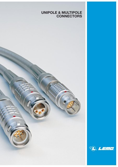
®® ®Precision modular connectors to suit your applicationSince it’s creation in Switzerland in 1946 the LEMO Group has been recognized as a global leader of circular Push-Pullconnectors and connector solutions. Today LEMO and its affiliated companies, REDEL and COELVER, are active inmore than 80 countries with the help of over 40 subsidiaries and distributors.Over 50’000 connectorsThe modular design of the LEMO range provides over 50’000 connectors from miniature ø 3 mm to ø 50 mm, capable ofhandling cable diameters up to 30 mm and for up to 106 contacts.This vast portfolio enables you to select the ideal connector configuration to suit almost any specific requirement in mostmarkets, including medical devices, test and measurement instruments, machinery, audio video broadcast, telecommunicationsand military.LEMO’s Push-Pull Self-Latching Connection SystemThis self-latching system is renowned worldwide for its easy and quick mating and unmating features. It provides absolutesecurity against vibration, shock or pull on the cable, and facilitates operation in a very limited space.The LEMO self-latching system allows the connectorto be mated by simply pushing the plug axially into thesocket.Once firmly latched, connection cannot be broken bypulling on the cable or any other component part otherthan the outer release sleeve.When required, the connector is disengaged by asingle axial pull on the outer release sleeve. This firstdisengages the latches and then withdraws the plugfrom the socket.UL RecognitionLEMO connectors are recognized by the Underwriters Laboratories (UL). The approval of the complete system (LEMOconnector, cable and your equipment) will be easier because LEMO connectors are approved.CE markingCE marking means that the appliance or equipment bearing it complies with the protection requirements of one orseveral European safety directives. CE marking applies to complete products or equipment, but not to electromechanicalcomponents, such as connectors.RoHSLEMO connectors are in compliance with the RoHS directives (2002/95/EC) of the European Parliament. This directivespecifies the restrictions of the use of hazardous substances in electrical and electronic equipment marketed in Europe.LEMO guarantees that its connectors are free of mercury, cadmium, lead, hexavalent chromium and polybromidebiphenyl (PBB) or polybromide diphenyl ether (PBDE).2www.lemo.com
® ®3 steps to select the right connector● Step 1: Select connector seriesSelect the appropriate LEMO connector series according to the environmental parameters that will affect your deviceor cable such as indoor, outdoor, temperature range, ingress protection of the mated connector and of your device.Use the table shown on page 4.Part number coding.. .B, K, S, E, L, G, C or D● Step 2: Select connector sizeUse the section (mm 2 ) or the AWG of your cable wire to select the optimal contact diameter (values vary betweensolder, crimp or print contact), see page 7.Use this optimal contact diameter to determine the right connector size as well as the insert configuration, see page 6.Part number coding. . .0, 1, 2, 3, 4, 5 or 6● Step 3: Complete the part numberNow that you know the series, as well as the insulator configuration, complete the part numbering system with the helpof the following table.Part number coding. . .Insert Housing InsulatorModel Seriesconfiguration material materialContact Collet VariantB Series (indoor, keyed)K Series (outdoor, keyed)S Series (indoor, stepped insert)E Series (outdoor, stepped insert)L Series (outdoor, keyed, stepped insert)G Series (indoor, keyed)C Series (indoor, stepped insert)D Series (indoor, 4 concentric contacts)12 12 45 50 50 50 52 5434 34 45 50 50 50 53 5458 58 91 99 99 99 102 10776 76 91 99 99 99 105 10786 86 92 99 99 99 106 107111 111 112 112 110 113 113 113117 117 120 120 116 120 121 121125 125 127 127 124 127 127 128Note: Figures in the above table refer to the catalogue pages.www.lemo.com3
® ®Step 1: Select Connector SeriesLEMO unipole and multipole connectorsThe standard keyed Series (B, 00, G)The characteristic feature of these connector series is a keying system which allows higher contact density and preventsall errors in alignment. The various keying alternatives prevent unwanted cross mating of otherwise similar connectors. Itis also possible to use crimp contacts to reduce cable assembly time. These connector series, include the 0B to 5B rangeas well as the 00 multipole and 2G (shortened version of the 2B series), some vacuumtight models are also available.The watertight keyed Series (K, L)These series are watertight when mated and assembled to an appropriate cable. They include the 0K to 5K series, availablein the same types as the 0B to 5B series, and the 0L to 2L series with keying and hermaphroditic insulator.The standard Series (S, 00, C, D)The characteristic feature of these connector series is the hermaphroditic insulator in the multipole version. They includeprincipally the 0S and 6S series, as well as the 00 unipole series, the 2C (shortened version) and the 1D quadrax type(with 4 concentric contacts).The watertight Series (E)These series are watertight when mated and assembled to an appropriate cable. They include the 0E to 6E series andare available in the same types as the S series.SeriesEnvironmentIngress 1)protectionIngress 2)protectionTemperaturerangeLatching00 multipoleBK00 unipoleSindooroutdoor orindoorharsh env.outdoor or harsh environmentIP50 IP66 to IP68 IP50 IP66 to IP68IP50 to IP68vacuumtightIP66 to IP68vacuumtightIP50 to IP68vacuumtightE LGC DIP66 to IP68vacuumtight- 55 to 250°C - 55 to 200°C - 55 to 250°C - 55 to 200°C - 55 to 250°C- 40 to 120°CPush-Pull self-latchingIP50indoorIP50IP50 to IP68vacuumtightIP50Shell sizesInsulator typeContact typeFeatures7 metaland 4 plasticMultipole6 metalSolder, crimp or print7 metaland 5 plasticUnipole or multipolehermaphroditicSolder or print13 keyways 9 keyways Stepped insert6 metal 3 metal 4 metal 1 metalMultipolehermaphroditicSolder, crimpor printSteppedinsertMultipole1 keywaySolder or printMultipolehermaphroditicSteppedinsertQuadraxSolder4 concentriccontactsPage9 to 31 32 to 44 55 to 73 74 to 83 84 to 90 109 to 115 116 to 122 123 to 128Note:1) Mated connector. See ingress protection code page 5.2) Your device. For selection of connectors for watertight and vacuumtight devices, see page 5.4www.lemo.com
® ®Definition of Ingress Protection (IP code)IEC 60529 outlines an international classification systemfor the sealing effectiveness of enclosures of electricalequipment against the intrusion into the equipment of foreignbodies (i.e. tools, dust, fingers) and moisture. Thisclassification system utilizes the letters «IP» (Ingress Protection)followed by two digits.Degrees of protection - First digitThe first digit of the IP code indicates the degree to whichpersons are protected against contact with moving partsand the degree that equipment is protected against solidforeign bodies intruding into an enclosure.Example: IP 50 = IP 5 0IP letter code1st digit2nd digitDegrees of protection - Second digitThe second digit indicates the degree of protection of theequipment inside the enclosure against the harmful entryof various forms of moisture (e.g. dripping, spraying, submersion,etc.)CodeFirst digit descriptionCodeSecond digit description0No special protection0No special protection1Protection from a large part of the body such as handor from solid objects greater than 50 mm in diameter1Protection from vertically dripping water2Protection against objects not greater than 80 mm in lengthand 12 mm in diameter2Protection from dripping water when tilted up to 15°3Protection from entry by tools, wires, etc.,with a diameter or thickness greater than 2.5 mm3Protection from sprayed water4Protection from entry by solid objectswith a diameter or thickness greater than 1.0 mm4Protection from splashed water5Protection from the amount of dust that would interferewith the operation of the equipment5Protection from water projected from a nozzle6Dust-tight6Protection against heavy seas, or powerful jets of water7–7Protection against temporary immersion8–8Protection against complete continuous submersion in waterSelection of connectors for watertight or vacuumtight devicesLEMO B and S series are rated IP50 only when mated. LEMO E, K and L series are rated IP66 (and over) only whenmated. If a device must be watertight or vacuumtight when the connectors are unmated, it is important to select a watertightor vacuumtight socket. You can consider the following two situations:A) Figure 1 shows a typical outdoor device. To ensure thisdevice retains IP66 or above when connectors areunmated, it is important to choose a watertight socketfrom B, S, E, K or L series.B) Figure 2 shows a device which is subjected to pressuredifference such as a near vacuum or pressurized gasand must exhibit no leakage. To ensure the devicemaintains its sealing, the socket is additionally tested forhelium leakage (according MIL 1344A).Fig. 1 Fig. 2your deviceyour deviceepoxyresin sealFGG plug K seriesEGG socket K seriesFGG plug B seriesHGG socket B seriesCheck temperature range (see section on pages 26, 41, 72, 82 and 89).www.lemo.com5
® ®Step 2: Select Connector SizeSelect the right connector size and insert configurationTo be able to select the right connector size (0 to 6), it is important to define the contact diameter (ø A).Find out the available contact diameter (ø A) of the LEMO connector depending on the number of contacts required anddepending on the rating required (see pages 45 to 49 and 91 to 98).The following table shows the contact diameter (ø A), or the solder pot diameter (ø C) for the 1D series.SeriesNumber of contactsInsert configuration000B-0K1B-1K2B-2K3B-3K4B-4K5B-5K000S-0E-0L 1)1S-1E-1L 1)2S-2E-2L 1)3S-3E4S-4E5S-5E6S-6E2G2CUnipole1D (ø C)Multipole11111112345678910121314161819202224263032364044485054606264721061131161201301401601123023033043053063073083093103123133143163183193203223243263303323363403443483503543603623643721061.31.62.03.0 3.04.0 4.0 4.06.0 6.00.5 0.9 1.3 2.0 3.0 6.0 0.9 1.3 1.6 2.0 4.0 6.0 1.60.5 0.9 1.3 1.6 2.0 0.7 0.9 1.3 2.0 3.0 6.0/4.0 6.0 1.30.5 0.7 0.9 1.3 2.0 3.0 4.0 0.7 0.9 1.3 2.0 3.0 4.0 8.0 1.3 0.60.7 0.9 1.3 1.6 0.9/0.7 1.3 2.0/1.3 3.0/2.0 4.0/3.00.5 0.7 1.3 1.6 2.0 0.7 1.3 1.3 2.0 3.0 1.30.5 0.7 1.3 1.6 2.0 1.3/0.9 1.3 2.0/1.30.7 0.9 1.3 0.9 1.3 1.3 3.0 0.70.5 1.3/2.0 1.30.5 0.9 1.3 1.6 3.0 0.9 1.3 1.3 2.0 0.70.7 0.9 1.3 0.9 1.3 2.0 4.0/5.0 0.70.9 1.30.5 0.7 0.9 2.0 0.9 1.3 3.0/2.0 0.70.5 0.7 0.9 0.9 2.0 0.9 0.9 2.0 3.00.7 0.9 0.9 0.9 3.0/1.6 4.0 0.70.70.7 0.9 1.6 0.9 1.6 3.00.7 0.9 3.0/1.60.7 0.9 0.9 1.6 3.00.5 0.70.7 0.9 1.3 1.3 2.00.5 2.01.3 2.0 2)0.7 1.3 1.3 2.01.30.7 1.3 1.3 2.00.90.91.61.60.9 1.31.30.912.0Note: 1) L series not available in unipole version. 2) 2.0 is for 6S series, for 6E the values are 1.3 and 5.0.6www.lemo.com
® ®Verify the fitting to your wireVerify if the selected contact diameter (ø A) of the LEMO connector fits to your cable wire diameter (AWG number ormax. available section).Contact typeContactø A ø C Form(mm) (mm) per fig.AWGmax.SolidSectionmax.(mm 2 )ConductorStrandedAWG Section (mm 2 )min. max. min. max.F r1)(N)Notefig. 1fig. 2ø Aø Aø Aø Aø Aø Aø Cø Cø Cø Cø Cø C0.5 2) 0.40 2) –0.5 0.45 –0.7 3) 0.60 3) –0.7 0.80 –0.9 0.80 –1.3 1.00 –1.6 1.40 –2.0 1.80 –3.0 2.70 –4.0 3.70 –5.0 5.20 –6.0 5.20 –8.0 7.00 –12.0 11.50 –0.5 5) 0.45 10.70.80 10.45 21.10 10.9 0.80 20.45 21.40 11.3 1.10 20.80 21.61.90 11.40 22.02.40 11.90 23.0 2.90 14.0 4.00 1Solder 28 0.09 – 30 – 0.05 –Crimp28 0.09 – 28 – 0.09 –24 0.25 – 26 – 0.14 –22 0.34 – 22 4) – 0.34 –22 0.34 – 22 4) – 0.34 –20 0.50 – 20 4) – 0.50 –16 1.00 – 18 – 1.00 –14 1.50 – 16 – 1.50 –10 4.00 – 12 – 4.00 –10 6.00 – 10 – 6.00 –– – – 8 – 10.00 –– – – 8 – 10.00 –– – – 4 – 16.00 –– – – 0 – 50.00 –– – 32 28 0.035 0.09 12– – 26 22 4) 0.140 0.34– – 32 28 0.035 0.0922– – 24 20 0.250 0.50– – 26 22 4) 0.140 0.34 30– – 32 28 0.035 0.09– – 20 18 0.500 1.00– – 24 20 0.250 0.50 40– – 26 22 4) 0.140 0.34– – 18 14 4) 1.000 1.50– – 22 18 0.340 1.0050– – 16 12 4) 1.500 2.50– – 18 14 1.000 1.5065– – 14 10 4) 2.500 4.00 75– – 12 10 4.000 6.00 90●●●●●●●●●●●●●●●●ø APrintLø Cø Aø CL dimensions and C are detailed in the section on PCB drilling pattern.See page 156 and 159.●LPrint (elbow)ø ALL dimensions and C are detailed in the section on PCB drilling pattern.See page 157 and 160.●ø CNote:1) contact retention force in the insulator (according to IEC 60512-8 test 15 a).2) for 00 multipole series.3) for S, E, 2C, 2G and 1D series.4) for a given AWG, the diameter of some stranded conductor designs is larger than the solder cup diameter. Make sure that the maximum conductordiameter is smaller than ø C.5) for 00 multipole series or for 0B and 1B series with male contacts.www.lemo.com7
® ®Verify the fitting to your cableVerify if the selected connector size fits to your cable diameter.Cable diameter range (mm)Cable diameter range (mm)Cable diameter range (mm)SeriesColletCollet for fittinga bend reliefmin. max. min. max.SeriesColletCollet for fittinga bend reliefmin. max. min. max.SeriesColletCollet for fittinga bend reliefmin. max. min. max.00 1)0B1B2B3B4B5B0K1K2K3K4K5K1.1 3.4 1.1 3.41.5 5.5 1.5 5.02.2 7.5 2.2 7.01.5 9.7 1.5 9.04.1 11.7 4.1 11.05.1 16.0 5.1 15.09.6 25.0 9.6 15.51.0 5.0 1.0 5.01.3 8.5 3) 1.3 8.51.3 10.5 3) 1.3 10.52.6 15.0 3) 2.6 15.04.6 23.5 3) 4.6 15.09.6 23.5 – –00 2)0S1S2S3S4S5S6S0E1E2E3E4E5E6E0L1L2L1.1 4.1 1.1 4.11.3 6.7 1.3 6.11.3 8.5 1.3 8.01.3 10.5 1.3 10.02.5 13.0 2.5 13.04.1 22.0 4.1 13.06.1 30.0 – –11.1 30.0 – –1.0 5.0 1.0 5.01.3 8.5 3) 1.3 8.51.3 10.5 3) 1.3 10.52.6 15.0 3) 2.6 15.04.6 23.5 3) 4.6 15.09.6 23.5 – –13.0 30.0 – –1.0 5.0 1.0 5.01.3 8.5 3) 1.3 8.51.3 10.5 3) 1.3 10.52C2G1D2.2 8.1 2.2 8.14.5 7.9 4.5 7.93.1 7.5 3.1 7.0Note:1) for multipole only.2) for unipole only.3) for these series the maximum cable diameter require models with oversized cable collet (type K).8www.lemo.com
B SERIESK SERIES (watertight)
® ®B SeriesB series connectors provide the following main features:– security of the Push-Pull self-latching system – multipole types 2 to 64 contacts– solder, crimp or print contacts (straight or elbow) – high packing density for space savings– multiple key options to avoid cross mating – keying system («G» key standard)of similar connectorsfor connector alignment– 360° screening for full EMC shielding.Metal housing models (page 12)Fixed plugs Straight plugs Fixed sockets Free socketsFWGFGGEGGECGPHGFAGFGGENGECGPHGElbow plugsJGGEKGEZGPNGFHGFixed socketsFFGESGEYGPKGFMGFNGEHGXPFFixed couplerPFGFEGEJGFKGFDGEEGR••PEGFIGEFGElbow socket models (page 22)Elbow socketsECGEPGXBG, EXGPlastic housing models (page 24)Straight plugsFixed socketsBridge models (page 29)Plug with twoparallel socketsBridge plugsFGGFGGENGFTGFGYFGYENYCFF, CRGWatertight or vacuumtight models (page 26)FixedplugFixed socketsFixedcouplerThreaded-latching models (page 30)Straight plugsFixed socketHGGHHGHEGFVGESGElbow socketYHGS••HNGHCGHMGFVBXRB10 www.lemo.com
® ®Part Numbering SystemPlugFG G . 1B . 306 .C L A D 62Free socketPH G . 1B . 306 . C L L D 62ZVariant: (page 54)Cable ø: (page 52)Collet type: (page 52)Fixed socket EG G . 1B . 306 . C Y MCoupler RJ G . 1B . 306 . C L AModel: (page 12)Alignment key: (page 31)Series: (page 12)Insert configuration: (page 45)Variant: (page 54)Contact: (page 50)Insulator: (page 50)Housing: (page 50)Part Number ExampleStraight plug with cable collet:FGG.1B.306.CLAD62 = straight plug with key (G) and cable collet, 1B series, multipole type with 6 contacts, outer shell inchrome-plated brass, PEEK insulator, male solder contacts, D type collet for 6.0 mm diameter cable.Free socket:PHG.1B.306.CLLD62Z = free socket with key (G) and cable collet, 1B series, multipole type with 6 contacts, outer shellin chrome-plated brass, PEEK insulator, female solder contacts, D type collet for 6.0 mm diameter cable and nut for fittinga bend relief.Fixed socket:EGG.1B.306.CYM = fixed socket, nut fixing, with key (G), 1B series, multipole type with 6 contacts, outer shell in chromeplatedbrass, PEEK extended insulator, female crimp contacts.Fixed coupler:RJG.1B.306.CLA = straight fixed coupler with keys (J) at the flange end and key (G) at the other end, 1B series, multipoletype with 6 contacts, outer shell in chrome-plated brass, PEEK insulator, male-female contacts.Part Section Showing Internal ComponentsFixed socket7623 4 511 6 5 4 2 7 3Straight plug1234567outer shellearthing crownretaining ringhexagonal nutlocking washerinsulatorfemale contact1234567outer shelllatch sleevecollet nutsplit insert carrierinsulatormale contactcolletwww.lemo.com11
® ®Metal housing modelsTechnical CharacteristicsMechanical and ClimaticalElectricalCharacteristics Value StandardCharacteristicsValueStandardEnduranceHumidityTemperature rangeResistance to vibrationShock resistanceSalt spray corrosion testProtection index (mated)Climatical category> 5000 cycles IEC 60512-5 test 9aup to 95% at 60° C- 55° C, +250° C10-2000 Hz, 15 g IEC 60512-4 test 6d100 g, 6 ms IEC 60512-4 test 6c> 144h IEC 60512-6 test 11fIP50 IEC 6052955/175/21 IEC 60068-1Shieldingefficiencyat 10 MHzat 1 GHz> 75 dB IEC 60169-1-3> 40 dB IEC 60169-1-3Note:the various tests have been carried out with FGG and EGG connectorpairs, with chrome-plated brass shell and PEEK insulator.Detailed electrical characteristics, as well as materials and treatment arepresented in the chapter Technical Characteristics on page 171.FGG Straight plug, key (G) or keys(A…M and R), cable colletReferenceDimensions (mm)ModelSeriesA L M S1 S2S 2~MS 1~Lø AFGG 00 1)FGG 0BFGG 1BFGG 2BFGG 3BFGG 4BFGG 5B6.4 28.5 20.5 5.5 59.5 36.0 26.0 8.0 712.0 43.0 32.0 10.0 915.0 50.0 38.0 13.0 1218.0 58.0 43.0 15.0 1425.0 75.0 57.0 21.0 2035.0 103.0 78.0 31.0 30Note: 1) the surface design of the 00 series is different.M1Cable assembly(page 161)FGG Straight plug, key (G) or keys (A…M),cable collet and nut for fitting a bend relief 2)ReferenceDimensions (mm)ModelSeriesA L M S1 S2~M~Lø AFGG 00 1)FGG 0BFGG 1BFGG 2BFGG 3BFGG 4B6.4 36.5 28.5 5.5 69.5 35.0 25.0 8.0 712.0 42.0 31.0 10.0 915.0 49.0 37.0 13.0 1218.0 56.5 41.5 15.0 1525.0 71.0 53.0 21.0 20M1Cable assembly(page 161)S 2S 1Note: 1) the surface design of the 00 series is different.2) to order, add a «Z» at the end of the reference.The bend relief must be ordered separately (see page 141).JGG Straight plug, short version, key (G),cable collet~M~LReferenceModel SeriesJGG 0BDimensions (mm)A L M S1 S29.5 32.0 22.0 8.0 7ø AM4 Cable assembly (page 161)S 2S 112 www.lemo.com
® ®FFGStraight plug, non-latching, key (G)or keys (A…M), cable colletReferenceDimensions (mm)ModelSeriesA L M S1 S2~M~Lø AFFGFFGFFGFFGFFG0B1B2B3B4B9.5 36 26 8 712.0 43 32 10 915.0 50 38 13 1218.0 58 43 15 1425.0 75 57 21 20S 2S 1M1 Cable assembly (page 161)FNG Straight plug, key (G) or keys (A…M and R),cable collet and lanyard releaseReferenceDimensions (mm)ModelSeriesA B L M N S1 S2N~M~Lø ABFNGFNGFNGFNGFNGFNG0B1B2B3B4B5B9.5 15.5 36.0 26.0 140 8 712.0 18.0 43.0 32.0 140 10 915.0 21.0 49.0 37.0 160 13 1218.0 25.0 58.0 43.0 190 15 1425.0 35.2 75.0 57.0 230 21 2035.0 47.0 103.0 78.0 300 31 30M1 Cable assembly (page 161)S 2 S 1Note: cable material: stainless steel with Polyamide sheath.In 4B and 5B series the outer shell design is similar to the PNG model.FEGStraight plug, key (G) or keys (A…L),cable collet, front sealand nut for fitting a bend relief 1)(IP 54 protection index when mated)ReferenceDimensions (mm)~LModelSeriesA L M S1 S2~Mø AFEGFEGFEGFEG0B1B2B3B11.0 35.0 25.0 8 713.5 42.0 33.0 10 916.5 48.0 36.0 13 1219.0 56.5 41.5 15 15M1Cable assembly(page 161)S 2S 1Note: 1) to order, add a «Z» at the end of the reference.The bend relief must be ordered separately (see page 141).FDG Straight plug, long version,key (G) or keys (A…L), cable colletReferenceDimensions (mm)~LModelSeriesA L M S1 S2~MFDGFDG1B2B12 68 57 10 915 79 67 13 12ø AM2 Cable assembly (page 162)S 2S 1www.lemo.com13
® ®FIGStraight plug for remote handling, key (G)or keys (A…L and R), special alignment mark,knurled handling surface, cable colletReferenceDimensions (mm)ModelSeriesA L M N S1 S2 S3~M~LNø AFIGFIGFIGFIG2B3B4B5B20 49 37 17.5 13 12 1522 58 43 21.5 15 14 1830 75 57 28.5 21 20 2540 103 78 41.0 31 30 35S 2S 1 S 3M1 Cable assembly (page 161)FWG Fixed plug, nut fixing, key (G) or keys (A…L)L maxiNS 3MReferenceDimensions (mm)ModelSeriesA B e E L M N 1) S1 S3ø Beø AFWGFWG1B2B18.0 15.8 M12x1.0 2.9 24.9 17 24.8 10.5 1419.5 19.2 M15x1.0 4.1 28.6 18 27.3 13.5 17E maxiS 1P9 Panel cut-out (page 152)Note: 1) maximum length with crimp contactsFAG Fixed plug, non-latching, nut fixing,key (G) or keys (A…M and R)ReferenceDimensions (mm)ø BeS 3E maxiL maxiNMS 1ø AModelSeriesFAG 00FAG 0BFAG 1BFAG 2BFAG 3BFAG 4BFAG 5BA B e E L M N 1) S1 S38 10.2 M7x0.5 2.9 18.1 9.0 15.0 6.3 910 12.4 M9x0.6 4.2 20.8 11.2 18.9 8.2 1114 15.8 M12x1.0 5.4 25.2 12.5 21.6 10.5 1418 19.2 M15x1.0 6.0 28.7 13.8 23.9 13.5 1722 25.0 M18x1.0 5.8 32.1 17.0 30.2 16.5 2229 34.0 M25x1.0 6.8 37.1 20.5 34.7 23.5 3040 40.0 M35x1.0 6.8 47.1 28.0 42.8 33.5 –P1 Panel cut-out (page 152)Note: 1) maximum length with crimp contacts. The 5B series is delivered withoutlocking washer or tapered washer and with a round nut.FHG Elbow (90°) plug, key (G) or keys(A…M and R), cable colletLReferenceDimensions (mm)S 1MModelSeriesA D H L M S1 S2 S3~HDS 3S 2ø AFHG 00 1)FHG 0BFHG 1BFHG 2BFHG 3BFHG 4BFHG 5B7.7 5.2 18.0 24.5 16.5 7 5 5.511.0 6.5 26.0 31.6 21.6 10 7 8.013.5 8.0 30.5 36.0 25.0 11 9 10.016.5 9.0 34.0 41.5 29.5 14 12 13.019.0 10.0 37.0 50.0 35.0 17 14 15.026.0 15.0 52.0 67.0 49.0 22 20 21.036.0 21.0 74.0 90.0 65.0 32 30 31.0M3 Cable assembly (page 161)Note: 1) the surface design of the 00 series is different.14 www.lemo.com
® ®S 1MLFMG Elbow (90°) plug, key (G) or keys (A…M),cable collet and lanyard release, long keyø A~HS 3S 2ReferenceModel SeriesFMG 0BDimensions (mm)A B H L M N S1 S2 S311 17 26 31.6 21.6 140 10 7 8NBM3 Cable assembly (page 161)Note: cable material: stainless steel with Polyamide sheathS 1MLFKG Elbow (90°) plug for remote handling, key (G)or keys (A…L), special alignment mark,knurled handling surface, cable collet~HNS 4S 3S 2ReferenceModel SeriesFKG 3BFKG 4BDimensions (mm)A H L M N S1 S2 S3 S425 37 50 35 21.0 17 14 15 2132 52 67 49 28.5 22 20 21 26ø AM3 Cable assembly (page 161)Note: dimension D is the same as for the FHG model.EGG Fixed socket, nut fixing,key (G) or keys (A…M and R)ø BeL maxiNS 3E maxiMø AS 1ModelReferenceSeriesEGG 00EGG 0BEGG 1BEGG 2BEGG 3BEGG 4BEGG 5BDimensions (mm)A B e E L M N 1) S1 S38 10.2 M7x0.5 6.0 15.5 1.0 13.7 6.3 910 12.4 M9x0.6 7.0 20.7 1.2 19.1 8.2 1114 15.8 M12x1.0 7.5 23.0 1.5 21.1 10.5 1418 19.2 M15x1.0 8.5 26.7 1.8 24.6 13.5 1722 25.0 M18x1.0 11.5 30.7 2.0 28.1 16.5 2228 34.0 M25x1.0 12.0 35.7 2.5 34.1 23.5 3040 40.0 M35x1.0 11.0 43.5 3.0 39.6 33.5 –P1 Panel cut-out (page 152)Note: 1) maximum length with crimp contacts.The 5B series is delivered with a tapered washer and a round nut.ENG Fixed socket with earthing tag,nut fixing, key (G) or keys (A…M)L maxiReferenceDimensions (mm)NModelSeriesA B e E L M N 1) S1 S3ø BeS 3E maxiMø AS 1ENG 0BENG 1B 2)ENG 2BENG 3BENG 4BP1 Panel cut-out (page 152)10 12.4 M9x0.6 7.0 20.7 1.2 19.1 8.2 1114 15.8 M12x1.0 7.5 23.0 1.5 21.1 10.5 1418 19.2 M15x1.0 8.5 26.7 1.8 24.6 13.5 1722 25.0 M18x1.0 11.5 30.7 2.0 28.1 16.5 2228 34.0 M25x1.0 12.0 35.7 2.5 34.1 23.5 30Note: 1) maximum length with crimp contacts.2) for the 1B series the earthing tag is on the upper side.www.lemo.com15
® ®EKG Fixed socket, nut fixing, key (G) or keys(A…L and R), special alignment markon the frontL maxiNReferenceDimensions (mm)S 3MModelSeriesA B e E L M N 1) S1 S3ø BeE maxiø AS 1EKGEKGEKGEKG2B3B4B5B18 19.2 M15x1.0 8.5 26.7 1.8 24.6 13.5 1722 25.0 M18x1.0 11.5 30.7 2.0 28.1 16.5 2228 34.0 M25x1.0 12.0 35.7 2.5 34.1 23.5 3040 40.0 M35x1.0 11.0 43.5 3.0 39.6 33.5 –P1 Panel cut-out (page 152)Note: 1) maximum length with crimp contacts.The 5B series is delivered with a tapered washer and a round nut.ESG Fixed socket with two round nuts,key (G) or keys (A…L), long threaded shell(back panel mounting)L maxiNM3.2 miniReferenceDimensions (mm)ModelSeriesA B e E L M N 1) S1ø Beø AESG 00ESG 1B9.5 9 M7x0.5 4.2 15.5 2 13.7 –14.0 14 M12x1.0 8.0 23.0 2 21.1 10.5E maxi S 1P1 Panel cut-out 1B series (page 152)P2 Panel cut-out 00 series (page 152)Note: 1) maximum length with crimp contacts.EHG Fixed socket, nut fixing, key (G)or keys (A…M and R), and protruding shellL maxiReferenceDimensions (mm)NModelSeriesA B e E L M N 1) S1 S3ø BeS 3E maxiMS 1ø AEHG 00EHG 0BEHG 1BEHG 2BEHG 3BEHG 5B8.0 10.2 M7x0.5 2.0 15.5 8.5 13.7 6.3 910.0 12.4 M9x0.6 2.0 19.5 12.5 19.1 8.2 1114.0 15.8 M12x1.0 4.0 21.7 12.0 21.1 10.5 1418.0 19.2 M15x1.0 5.1 22.7 12.5 24.6 13.5 1722.0 25.0 M18x1.0 7.1 30.7 13.5 30.3 16.5 2240.0 40.0 M35x1.0 2.5 43.5 28.0 38.5 33.5 –P1 Panel cut-out (page 152)Note: 1) maximum length with crimp contacts.The 5B series is delivered without locking washer or tapered washer andwith a round nut.EJGFixed socket, press or adhesive fit,key (G) or keys (A…M)L maxiNReferenceDimensions (mm)MModelSeriesA B L M N 1)ø Bø AEJGEJGEJG0B1B2B9.2 8.35 20.7 1.5 19.112.5 11.20 23.0 1.5 21.116.5 14.00 26.7 1.5 24.6P5 Panel cut-out (page 152)Note: 1) maximum length with crimp contacts.16 www.lemo.com
® ®EEG Fixed socket, nut fixing, key (G) or keys (A…M and R)(back panel mounting)L maxiReferenceDimensions (mm)ø BS 2NS 1E maxiPMeø AModelSeriesEEG 00EEG 0BEEG 1BEEG 2BEEG 3BEEG 5BP1 Panel cut-out (page 152)A B e E L M N 1) P S1 S210 9.5 M7x0.5 2.3 15.5 2.5 13.7 6.0 6.3 7.512 12.5 M9x0.6 2.4 20.7 2.5 19.1 6.3 8.2 9.016 16.0 M12x1.0 6.5 23.0 3.5 21.1 11.0 10.5 13.020 20.0 M15x1.0 3.0 26.7 3.5 24.6 9.0 13.5 15.024 25.0 M18x1.0 5.0 30.7 4.5 28.1 12.0 16.5 20.041 40.0 M35x1.0 13.5 43.5 5.0 39.6 19.5 33.5 38.0Note: 1) maximum length with crimp contacts. The 3B and 5B series are delivered with aconical nut. The 5B series is delivered without locking washer or tapered washer.L maxiNPMEFGFixed socket, nut fixing, key (G) or keys (A…M),with two flats on the shell and O-ring(back panel mounting)ReferenceDimensions (mm)ModelSeriesA B e E L M N 1) P S2ø Beø AEFG0B12 12.5 M9x0.6 5.5 20.7 2.5 19.1 9 8S 2E maxiP2 Panel cut-out (page 152)Note: 1) maximum length with crimp contacts.ECG Fixed socket with two nuts, key (G) or keys (A…M and R)(back panel mounting)ø BeS 1L maxiNS 3E maxiMø AModelReferenceSeriesECG 00ECG 0BECG 1BECG 2BECG 3BECG 4BECG 5BDimensions (mm)A B e E L M N 1) S1 S310 10.2 M7x0.5 4.3 13.7 2.5 13.7 6.3 912 12.4 M9x0.6 5.5 20.7 2.5 19.1 8.2 1116 15.8 M12x1.0 6.0 23.0 3.5 21.1 10.5 1420 19.2 M15x1.0 6.5 26.7 3.5 24.6 13.5 1724 25.0 M18x1.0 9.0 30.7 4.5 28.1 16.5 2230 34.0 M25x1.0 10.0 35.7 4.5 32.6 23.5 3041 40.0 M35x1.0 9.0 43.5 5.0 39.6 33.5 –P1 Panel cut-out (page 152)Note: 1) maximum length with crimp contacts. The 3B, 4B and 5B series are deliveredwith a conical nut. The 5B series is delivered with a tapered washer and a round nut.ECG Fixed socket with two nuts, key (G) or keys (A…F and R)and straight contact for printed circuit(back panel mounting)ø BeLS 1S 3NE maxiMø AModelReferenceSeriesECG 00ECG 0BECG 1BECG 2BECG 3BECG 4BECG 5BDimensions (mm)A B e E M N S1 S310 10.2 M7x0.5 4.3 2.5 13.7 6.3 912 12.4 M9x0.6 5.5 2.5 16.4 8.2 1116 15.8 M12x1.0 6.0 3.5 19.8 10.5 1420 19.2 M15x1.0 6.5 3.5 21.8 13.5 1724 25.0 M18x1.0 9.0 4.5 25.8 16.5 2230 34.0 M25x1.0 10.0 4.5 29.8 23.5 3041 40.0 M35x1.0 9.0 5.0 36.8 33.5 –P1Panelcut-out(page 152)P15PCB drillingpattern(page 154)Note: this contact type is available for E●● socket models fitted with female contacts.Length «L» depends on the number of contacts, see table on page 156.The 5B series is delivered with a tapered washer and a round nut.The 3B, 4B and 5B series are delivered with a conical nut.www.lemo.com17
® ®ECG Fixed socket with two nuts, key (G) or keys(A…F) with elbow (90°) contact for printedcircuit (back panel mounting)ReferenceDimensions (mm)LS 3NS 1MModelSeriesA B e E M N S1 S3max20 miniE maxieø Aø BECGECGECGECG0B1B2B3BP1 Panel cut-out (page 152)12 12.4 M9x0.6 2.4 2.5 18.3 8.2 1116 15.8 M12x1.0 6.0 3.5 20.3 10.5 1420 19.2 M15x1.0 6.5 3.5 22.3 13.5 1724 25.0 M18x1.0 9.0 4.5 25.8 16.5 222P17 PCB drilling pattern (page 157)Note: this female contact type is available for all back panel mountingsocket models. Length «L» depends on the number of contacts, see PCBdrilling pattern on page 157.For male contacts, sockets are available upon request, with J, K or L keys.The 3B series is delivered with a conical nut.EZGStraight socket for printed circuit,key (G) or keys (A, B)ReferenceDimensions (mm)ø 0.7ø 0.53Nø ABHModel Series A B H K NEZG 00 6.8 7 5.08 7 14P15 + P16 PCB drilling pattern (pages 154 and 156)KEZGStraight socket for printed circuit,key (G) or keys (A…F)ReferenceDimensions (mm)ModelSeriesA B H K NM 1.6LNBHEZGEZGEZG0B1B2B9 10 7.62 8 15.011 12 7.62 8 19.014 15 10.16 9 22.5ø AP15 + P16PCB drilling pattern (pages 154 and 156)KNote:Length «L» depends on the number of contacts, see table on page 156.EYG Fixed socket for printed circuit, nut fixing,key (G) or keys (A…F) (back panel mounting)ReferenceDimensions (mm)ModelSeriesA B C e E M N P S1M 1.6L9S 1NPMB7.62EYGEYG0B1BP1 Panel cut-out 0B series (page 152)P10 Panel cut-out 1B series (page 152)12 10 12.5 M9x0.6 2.6 2.5 15 6 8.214 12 16.0 M11x0.5 5.0 3.5 19 10 –ø Ceø AP15 + P16PCB drilling pattern (pages 154 and 156)E maxiNote:Length «L» depends on the number of contacts, see table on page 156.18 www.lemo.com
® ®XPFFixed socket, nut fixing, long shell,keys (F) for printed circuit(back panel mounting)LNPM5.08ReferenceModel SeriesXPF 0BDimensions (mm)A B e E M N P R12 11 M9x0.6 1.5 2.5 19 5 4ø Beø AP2Panel cut-out (page 152)P15 + P16PCB drilling pattern (pages 154 and 156)RE maxi1Note:Length «L» depends on the number of contacts, see table on page 156.PHG Free socket, key (G) or keys (A…M and R),cable colletReferenceDimensions (mm)ModelSeriesA L S1 S2S 2S 1~Lø APHG 00 1)PHG 0BPHG 1BPHG 2BPHG 3BPHG 4BPHG 5BM1 Cable assembly (page 161)6.8 26.0 5.5 59.5 35.5 8.0 712.5 40.5 10.0 916.5 47.0 13.0 1219.0 56.0 15.0 1426.0 73.0 21.0 2036.0 99.0 31.0 30Note: 1) the surface design of the 00 series is different.PHG Free socket, key (G) or keys (A…M),cable collet and nut for fitting a bend relief 2)ReferenceDimensions (mm)ModelSeriesA L S1 S2~Lø APHG 00 1)PHG 0BPHG 1BPHG 2BPHG 3BPHG 4B6.8 34.0 5.5 69.5 34.5 8.0 712.5 39.5 10.0 916.5 46.0 13.0 1219.0 54.5 15.0 1526.0 69.0 21.0 20S 2 S 1M1 Cable assembly (page 161)Note: 1) the surface design of the 00 series is different.2) to order, add a «Z» at the end of the reference.The bend relief must be ordered separately (see page 141).www.lemo.com19
® ®PNG Free socket, nut fixing, key (G) or keys(A…L and R), cable collet with lanyard releaseReferenceDimensions (mm)ModelSeriesA B L N S1 S2~LPNGPNGPNGPNGPNG1B2B3B4B5B12.5 20.0 40.5 140 10 916.5 24.2 47.0 160 13 1219.0 26.6 56.0 190 15 1426.0 36.2 73.0 230 21 2036.0 48.0 99.0 300 31 30Nø ABM1 Cable assembly (page 161)Note: cable material: stainless steel with Polyamide sheathS 2 S 1PKG Fixed socket, nut fixing, key (G)or keys (A…M and R), cable colletReferenceDimensions (mm)ModelSeriesA B e E L M S1 S2 S3~LeS 3Mø Aø BPKG 00PKG 0BPKG 1BPKG 2BPKG 3BPKG 4BPKG 5B8 10.2 M7x0.5 6.5 26.0 1.0 6.3 5 910 12.4 M9x0.6 7.0 35.5 1.2 8.2 7 1114 15.8 M12x1.0 7.5 40.5 1.5 10.5 9 1418 19.2 M15x1.0 8.5 47.0 1.8 13.5 12 1722 25.0 M18x1.0 11.5 56.0 2.0 16.5 14 2228 34.0 M25x1.0 12.0 73.0 2.5 23.5 20 3040 40.0 M35x1.0 11.0 99.0 3.0 33.5 30 –P1 Panel cut-out (page 152)S 2E maxiS 1M1 Cable assembly (page 161)Note: the 5B series is delivered with a tapered washer and a round nut.PFGFixed socket, with two nuts, key (G) or keys(A…M and R), cable collet (back panel mounting)ReferenceDimensions (mm)ModelSeriesA B e E L M S1 S2 S3ø B~LeS 3Mø APFG 00PFG 0BPFG 1BPFG 2BPFG 3BPFG 4BPFG 5B10 10.2 M7x0.5 5.3 26.0 2.5 6.3 5 912 12.4 M9x0.6 5.0 35.5 2.5 8.2 7 1116 15.8 M12x1.0 5.0 40.5 3.5 10.5 9 1420 19.2 M15x1.0 6.5 47.0 3.5 13.5 12 1724 25.0 M18x1.0 9.0 56.0 4.5 16.5 14 2230 34.0 M25x1.0 11.0 73.0 4.5 23.5 20 3041 40.0 M35x1.0 10.0 99.0 5.0 33.5 30 –P1 Panel cut-out (page 152)S 2S 1E maxiM1 Cable assembly (page 161)Note: the 3B, 4B and 5B series are delivered with a conical nut.The 5B series is delivered with a tapered washer and a round nut.20 www.lemo.com
® ®PEG Fixed socket, nut fixing, key (G) or keys (A…L),cable collet (back panel mounting)~LReferenceDimensions (mm)PModelSeriesA B e E L M S1 S2 S4 PS 1MPEGPEG3B4B24 22 M18x1.0 5.0 56 4.5 16.5 14 20 1232 34 M25x1.0 12.5 73 5.0 23.5 20 27 20ø BR ●●Fixed coupler, nut fixing, key (G) or keys (A and J) at the flange end and keys (J, K or M) at the other endLS 3Meeø Aø Bø AP1 Panel cut-out (page 152)S 2E maxiS 4M1 Cable assembly (page 161)Note: the 4B series has an o-ring on the flange.E maxiS 1ReferenceContactsDimensions (mm)G RGGGModelSeriesType A B e E L M S1 S3J RJGGG RGJJA RAKKG RGMMExampleRGG 1)RGG 2)RJGRGJRAKRGMRGG 2)RJGRGJRJGRGJRGJRGJ0B0B0B1B1B2B3B4Bfemale – female 12 13.8 M10x0.75 8.0 34 2.0 9.0 12female – female 12 13.8 M10x0.75 8.0 43 2.0 9.0 12male – femalefemale – malefemale – male12 13.8 M10x0.75 8.0 34 2.0 9.0 12female – malefemale – female 16 19.2 M14x1.00 8.5 47 2.5 12.5 17male – femalefemale – male16 19.2 M14x1.00 8.5 39 2.5 12.5 17male – femalefemale – male20 21.5 M16x1.00 12.0 44 4.0 15.0 19female – male 25 27.0 M20x1.00 32.0 53 4.0 18.5 24female – male 34 34.0 M25x1.00 50.0 65 4.0 23.5 30RGJPlug with key GPlug with key JAlignment key see page 31.P4 Panel cut-out (page 152)Note:1) only available with two contacts.2) only available with three contacts.For this fixed coupler, the first contact type mentioned is always the one at the flange end. On request, thesecouplers can be produced in other series, with other keys.www.lemo.com21
I® ®Elbow socket modelsTechnical CharacteristicsTypesSeries1 2Series1Type000B, 1B30221 21 2000B, 1B303331 21 2000B, 1B3044 34 31 2 30B, 1B3055 41 2 30B, 1B3066 5 41 2 30B, 1B7 3076 5 42 3 41B 1 8 3087 6 51 2 3 40B 98 7 563091 2 3 41B 9 108 7 563101212 31 42 312 53 41 62 53 41 62 7 53 4123 8764 51 82 7934 5 61 82 9 73 104 5 6Materials and TreatmentHousingComponentMetallic partsEarthing crownInsulatorFemale contactEPG-XBG 00EPG-EXG 0BEPG-EXG 0BEPG-EXG 0BEPG-EXG 0BEPG-EXG 0BEPG-EXG 0BEPG-EXG 0BEPG-EXG 1BEPG-EXG 1BEPG-EXG 1BEPG-EXG 1BEPG-EXG 1BEPG-EXG 1BEPG-EXG 1BEPG-EXG 1BEPG 1BSurfaceMaterial treat. (µm)Cu Ni AuPPS –Brass 0.5 3 –Brass 0.5 3 –Bronze 0.5 3 –PEEK –Bronze 0.5 3 1.5Note:The surface treatment standards are as follows:– Nickel: FS QQ-N-290A. – Gold: ISO 4523ElectricalModelSeriesTypes302-303-304302303304305306307309302303304305306307308310314Test voltage(kV rms)1)Contact-contactTest voltage(kV rms)1)Contact-shellRatedcurrent (A)1)1.00 1.00 2.01.45 1.20 4.51.70 1.60 4.51.30 1.10 4.51.25 1.20 4.51.25 1.20 2.51.25 1.20 2.01.00 1.10 1.51.70 1.45 4.51.60 1.85 4.51.70 1.80 4.51.30 1.55 4.51.35 1.45 4.51.45 1.45 2.01.30 1.30 2.01.00 1.00 1.51.00 1.00 1.0Note:1) see calculation method, caution and suggested standard on page 178.EPG Elbow (90°) socket for printed circuit,key (G) or keys (A…F) (solder or screw fixing)12.7ø ANKLReferenceEPG.1B.314.NLNDimensions (mm)A D H I K L N11 21 7.7 14.3 19 36 15.4P20 PCB drilling pattern (page 158)3Hø 0.7 ø 0.6M 1.6DNote: to replace the 4 ground pins by 4 screws (M1.6) add an «S» to theend of the part number. (e.g.: EPG.1B.314.NLNS)22 www.lemo.com
II® ®EPG Elbow (90°) socket for printed circuit,key (G) or keys (A…F) (solder or screw fixing)ReferenceDimensions (mm)A D H I K L N R3.0 (00)3.2 (0B-1B)Hø 0.7NRM 1.6ø 0.5 (00)ø 0.7 (0B-1B)KLDø AEPG.00.302.HLNEPG.00.303.HLNEPG.00.304.HLNEPG.0B.302.HLNEPG.0B.303.HLNEPG.0B.304.HLNEPG.0B.305.HLNEPG.0B.306.HLNEPG.0B.307.HLNEPG.0B.309.HLNEPG.1B.302.HLNEPG.1B.303.HLNEPG.1B.304.HLNEPG.1B.305.HLNEPG.1B.306.HLNEPG.1B.307.HLNEPG.1B.308.HLNEPG.1B.310.HLN6.8 11.5 3.5 7.0 8.7 19 7.1 5.089.0 14.6 6.7 12.7 13.3 25 11.7 7.6211.0 16.6 7.5 14.0 13.3 27 12.6 7.62P18 PCB drilling pattern 00 series (page 158)P19 PCB drilling pattern 0B, 1B series (page 158)Note: In the 0B and 1B series, it is possible to replace the 4 ground pins by 4 screws (M1.6)add an «S» to the end of the part number. (e.g.: EPG.0B.307.HLNS)EXG Elbow (90°) socket for printed circuit with two nuts,key (G) or keys (A…F) (solder or screw fixing)(back panel mounting)XBG Elbow (90°) socket fixing nut for printed circuit,key (G) or keys (A, B) (back panel mounting)ReferenceDimensions (mm)A B D e E H I K L M N R S33.0 (00)3.2 (0B-1B)HNRM 1.6ø 0.5 (00)ø 0.7 (0B-1B)KLS 3ø BE maxiDMeø AXBG.00.302.HLNXBG.00.303.HLNXBG.00.304.HLNEXG.0B.302.HLNEXG.0B.303.HLNEXG.0B.304.HLNEXG.0B.305.HLNEXG.0B.306.HLNEXG.0B.307.HLNEXG.0B.309.HLNEXG.1B.302.HLNEXG.1B.303.HLNEXG.1B.304.HLNEXG.1B.305.HLNEXG.1B.306.HLNEXG.1B.307.HLNEXG.1B.308.HLNEXG.1B.310.HLN10 10.2 11.5 M7x0.5 2.1 3.5 7.0 8.7 19 2.5 7.1 5.08 912 12.4 14.6 M9x0.6 6.0 6.7 12.7 13.3 25 2.5 11.7 7.62 1114 15.0 16.6 M11x0.5 7.5 7.5 14.0 13.3 27 3.5 12.6 7.62 13Note: In the 0B and 1B series, it is possible to replace the 4ground pins by 4 screws (M1.6) add an «S» to the end ofthe part number. (e.g.: EXG.0B.307.HLNS).www.lemo.comP2 Panel cut-out 00, 0B series (page 152)P10 Panel cut-out 1B series (page 152)P18 PCB drilling pattern 00 series (page 158)P19 PCB drilling pattern 0B, 1B series (page 158)23
® ®Plastic housing modelsThese connectors are particularly recommended for all applications requiring maximum electrical insulation when mated. Thedesign, including a latch sleeve and a metal earthing crown, guarantees EMC screening efficiency to meet most requirements.Technical CharacteristicsMechanical and ClimaticalCharacteristicsColourEnduranceHumidityTemperature rangeSterilization resistance 1)Resistance to solventsValuePEEK PSU PPSUStandardnatural (beige) white or grey cream –> 5000 cycles > 5000 cycles > 5000 cycles IEC 60512-5 test 9aup to 95% at 60° C –- 50° C/+250° C - 50° C/+150° C - 50° C/+180° C –> 200 cycles ~20 cycles > 100 cycles IEC 60601-1 § 44.7very good limited good –Note: 1) Steam sterilizationFGG Straight plug, key (G or J), cable collet,PEEK outer shellReferenceDimensions (mm)~M~Lø AModelFGGFGGFGGSeries1B3B4BM1 Cable assembly (page 161)A L M S213.5 43.0 32.0 1019.0 62.0 47.0 1526.0 78.5 60.5 20S 2FGG Straight plug, key (G or J), cable collet, PEEKouter shell and nut for fitting a bend relief 1)~M~LReferenceModel SeriesFGG 1BFGG 4BDimensions (mm)A L M S213.5 42.2 31.2 1026.0 83.2 65.2 20Note on availabilityfor all collet typeonly from collet M82 and upø AM1 Cable assembly (page 161)S 2Note: 1) to order, add a «Z» at the end of the reference.The bend relief must be ordered separately (see page 141).FGYStraight plug, keys (Y), cable colletand PSU or PPSU outer shellReferenceDimensions (mm)ModelSeriesA L M S2~M~LFGYFGYFGY2B3B4B16.5 50.5 39.5 1319.0 58.0 43.0 1526.0 76.2 58.2 20ø AM1 Cable assembly (page 161)S 224 www.lemo.com
® ®FGYStraight plug, keys (Y), cable colletand PSU or PPSU outer shell and nut for fittinga bend relief 1)ModelReferenceSeriesDimensions (mm)A L M S2Note on availability~M~LFGYFGYFGY2B3B4B16.5 49.5 38.5 1319.0 56.5 41.5 1526.0 74.4 56.4 20only for collet M42 and uponly for collet D62 and uponly for collet M82 and upø AM1 Cable assembly (page 161)S 2Note: 1) to order, add a «Z» at the end of the reference.The bend relief must be ordered separately (see page 141).ENG Fixed socket with earthing tag, nut fixing,key (G or J), PEEK outer shellL maxiNReferenceDimensions (mm)S 3MModelSeriesA B e E L M N 1) S1 S3ø Beø AENGENGENG1B3B4B14 15.8 M12x1.0 7.5 23.0 1.5 21.1 10.5 1422 25.0 M18x1.0 11.5 30.7 2.0 28.1 16.5 2228 34.0 M25x1.0 12.0 35.7 2.5 32.6 23.5 30E maxiS 1P1 Panel cut-out (page 152)Note: 1) maximum length with crimp contacts.ENYFixed socket with earthing tag, nut fixing,keys (Y), PSU or PPSU outer shellL maxiNReferenceDimensions (mm)S 3MModelSeriesA B e E L M N 1) S1 S3ø Beø AENYENYENY2B3B4B18 19.2 M15x1.0 8.5 26.7 1.8 24.6 13.5 1722 25.0 M18x1.0 11.5 30.7 2.0 28.1 16.5 2228 34.0 M25x1.0 12.0 35.7 2.5 32.6 23.5 30E maxiS 1P1 Panel cut-out (page 152)Note: 1) maximum length with crimp contacts.Note: other models with plastic outer shell are available on request.www.lemo.com25
® ®Watertight or vacuumtight modelsThese plug, socket and coupler models allow the device on which they are fitted to reach a protection index of IP68 as perIEC 60529. They are fully compatible with plugs of the same series and are widely used for portable radios, military, laboratoryequipment, aviation, etc.These models are identified by a letter «P» at the end of the reference.Most of these models are also available in a vacuumtight version. Such models are identified by an additional letter «V» atthe end of the part number (certificate on request).Epoxy resin is used to seal these models.Technical CharacteristicsMechanical and ClimaticalCharacteristics Value StandardCharacteristics Value StandardEnduranceHumidityTemperature range (00 to 1B)Temperature range (2B to 5B)Salt spray corrosion testClimatical categoryLeakage rate (He) 1)> 5000 cycles IEC 60512-5 test 9aup to 95% at 60° C- 20° C/+100° C- 20° C/+80° C> 144h IEC 60512-6 test 11f20/80/21 IEC 60068-1< 10 -7 mbar.l.s -1 IEC 60512-7 test 14bMaximum operatingpressure 2)000B1B2B3B4B5B60 bars60 bars60 bars40 bars IEC 60512-7 test 14d30 bars15 bars5 barsNote: 1) only for vacuumtight models.Note: 2) this value corresponds to the maximum allowed pressure differencefor the assembled socket.YHG Fixed plug, nut fixing, non-latching,key (G) or keys (A…M)L maxiReferenceDimensions (mm)S 3MModelSeriesA B e E L M S1 S3ø Beø AYHGYHGYHGYHG0B1B2B3B13.0 12.4 M9x0.6 2.4 24.1 14.2 8.2 1116.0 15.8 M12x1.0 3.9 28.0 16.2 10.5 1419.0 19.2 M15x1.0 5.5 33.1 17.8 13.5 1722.0 25.0 M18x1.0 5.1 38.2 22.2 16.5 22E maxiS 1P9 Panel cut-out (page 152)Note: this model does not include an O-ring behind the flange, it ensuresonly IP61 protection index. Consequently, it is not vacuumtight. Watertightness(when mated) is only ensured with HHG and HCG sockets.HGG Fixed socket, nut fixing, key (G) or keys(A…M and R), watertight or vacuumtightReferenceDimensions (mm)S 3L maxiMModelSeriesA B e E L M S1 S3ø BeE maxiS 1ø AHGG 00HGG 0BHGG 1BHGG 2BHGG 3BHGG 4BHGG 5B11 10.2 M7x0.5 8.0 18.0 1.5 – 913 12.4 M9x0.6 7.0 20.2 3.0 8.2 1118 15.8 M12x1.0 7.0 26.6 4.5 10.5 1420 19.2 M15x1.0 8.0 31.6 4.0 13.5 1725 25.0 M18x1.0 11.5 36.1 4.0 16.5 2234 34.0 M25x1.0 11.0 43.1 4.0 23.5 3045 40.0 M35x1.0 11.0 53.6 5.0 33.5 –P9 Panel cut-out (page 152)Note: the 5B series is delivered with a tapered washer and a round nut.26 www.lemo.com
® ®HNG Fixed socket, nut fixing, with earthing tag,key (G) or keys (A…M), watertight or vacuumtightL maxiReferenceDimensions (mm)S 3MModelSeriesA B e E L M S1 S3HNG 0B 13 12.4 M9x0.6 7 20.2 3 8.2 11ø Beø AP9 Panel cut-out (page 152)E maxiS 1HHG Fixed socket, nut fixing, key (G) or keys (A…M),watertight or vacuumtight (watertight when mated)ReferenceDimensions (mm)L maxiModelSeriesA B e E L M S1 S3ø BeS 3Mø AHHGHHGHHGHHG0B1B2B3B13 12.4 M9x0.6 7.0 23.2 4.8 8.2 1118 15.8 M12x1.0 7.0 30.3 5.2 10.5 1422 19.2 M15x1.0 8.0 35.6 6.0 13.5 1725 25.0 M18x1.0 11.5 41.3 7.2 16.5 22P9 Panel cut-out (page 152)E maxiS 1Note: this model ensures watertightness (IP66) in the mating area when mated with FGGor similar plug.HCG Fixed socket, nut fixing, key (G) or keys (A…M),watertight or vacuumtight(watertight when mated) (back panel mounting)F maxiL maxiPMModelHCGHCGHCGReferenceSeries0B1B2BDimensions (mm)A B C e e1 E F L M P S118 18 12.0 M14x1.0 M9x0.6 3.9 1.0 23.2 3.5 7.5 12.520 20 14.5 M16x1.0 M12x1.0 6.2 2.0 30.3 3.5 10.0 14.524 24 17.5 M19x1.0 M14x1.0 6.7 1.5 35.6 3.5 11.3 17.0ø Bø Ce 1eø AP3 Panel cut-out (page 152)S 1E maxiNote: this model ensures watertightness (IP66) in the mating area when mated with FGGor similar plug.HEG Fixed socket, nut fixing, key (G) or keys (A…M),watertight or vacuumtight (back panel mounting)ReferenceDimensions (mm)S2L maxiS1PMModelHEGHEGHEGSeries0B1B2BA B e E L M P S1 S212 13 M9x0.6 5.5 20.2 2.5 9.0 8.2 –16 18 M12x1.0 5.5 26.6 3.5 11.0 10.5 –20 20 M15x1.0 5.5 31.6 3.5 9.6 13.5 15ø Beø AP9 Panel cut-out (page 152)E maxiwww.lemo.com27
® ®L maxiHMG Fixed socket with earthing tag, nut fixing,key (G) or keys (A…M),watertight or vacuumtight (back panel mounting)PS1MReferenceDimensions (mm)ModelSeriesA B e E L M P S1ø Beø AHMGHMGHMG0B1B3B12 13 M9x0.6 5.5 20.2 2.5 9 8.216 18 M12x1.0 5.5 26.6 3.5 11 10.524 25 M18x1.0 7.5 36.1 4.5 14 16.5E maxiP9 Panel cut-out (page 152)Note: the 3B series is delivered with a conical nut.S ●●Fixed coupler, nut fixing, key (G) or keys (A, B, J, K and L) at the flange end and key (G)or keys (A, B, J, K and L) at the other end, watertight or vacuumtightLS 3S 1Mø Beø AE maxiReferenceContactsDimensions (mm)ModelSeriesType A B e E L M S1 S3G SGJJExampleJ SJGGK SKAAL SLBBA SAKKB SBLLSGJSJGSGJSJGSGJSJGSGJSJGSAKSBLSAKSBLSGJSJGSGJSJGSKASLBSAKSBL0B1B2B3B4B5Bfemale – malemale – femalefemale – malemale – femalefemale – malemale – femalefemale – malemale – femalefemale – malefemale – malefemale – malefemale – malefemale – malemale – femalefemale – malemale – femalemale – femalemale – femalefemale – malefemale – male14 13.8 M10x0.75 17 34 2.0 9.0 1217 15.8 M12x1.00 28 39 2.5 10.5 1420 21.5 M16x1.00 25 44 4.0 15.0 1925 27.0 M20x1.00 30 53 4.0 18.5 2434 34.0 M25x1.00 50 65 4.0 23.5 3045 40.0 M35x1.00 58 80 5.0 33.5 –SGJP4 Panel cut-out (page 152)Plug with key GPlug with key JP9 Panel cut-out 1B series (page 152)Alignment key see page 31.Note: for this fixed coupler, the first contact type mentioned is always the one at the flange end.On request these couplers can be produced in other series, with other keys.The 5B series is delivered with a round nut.28 www.lemo.com
® ®Bridge modelsTechnical CharacteristicsMechanical and ClimaticalCharacteristics Value StandardElectricalCharacteristics Value StandardEnduranceWorking temperature> 1000 cycles IEC 60512-5 test 9amaximum 90° CContact resistance< 6 mΩ IEC 60512-2 test 2aMaterials and TreatmentPlastic housingMetallic partsComponentInsulatorMale contactFemale contactMaterialSurface treat. (µm)Cu Ni Cr AuPolyamide –Brass 0.5 3 – –Brass 0.5 3 0.3 –PEEK –Brass 0.5 3 – 1.0Bronze 0.5 3 – 1.5Note: the surface treatment standards are as follows:– Nickel: FS QQ-N-290A, chrome: FS QQ-C-320B, gold: ISO 4523CFFCRGReferenceCFF.0B.302.PLCGCRG.0B.302.PLEGCFF.0B.303.PLCGCRG.0B.303.PLEGCRG.0B.306.PLEGCFF.1B.303.PLCGCRG.1B.303.PLEGCFF.1B.306.PLCGCRG.1B.306.PLEGSeriesNote: the last letter of the part number indicates the colour of the housing. Ex.G (standard) is grey. To obtain another colour, replace this letter by the lettercorresponding to the selected colour (see table on page 54).1) see calculation method, caution and suggested standard on page 178.2) lowest measured value; contact to contact or contact to shell.Audio-MonoAudio-StereoTest voltage(kV rms) 1) 2)Ratedcurrent (A)0B ● – 1.05 40B ● – 1.05 40B ● – 0.80 40B ● – 0.80 40B – ● 0.40 21B ● – 1.25 51B ● – 1.25 51B – ● 0.80 31B – ● 0.80 3CFFBridge plug with two non-latching plugsAM maxiCRGBridge plug with two non-latching plugs,and monitoring socket, key (G) or keys (A…M)ReferenceDimensions (mm)HBNModelSeriesA B H L M NCFF-CRGCFF-CRG0B1B13.5 14 27.5 37.2 27.2 22.515.0 20 35.0 42.0 31.0 22.0L maxiNote: in order to provide the user with a coding system, the bridge plug housing,the double panel washers and the bend reliefs are available in nine colours.FTGStraight plug, key (G) and two parallel sockets1537.827.8ReferenceFTG.0B.302.PLFGFTG.0B.303.PLFGFTG.0B.304.PLFG12Numberof contactsTest voltage(kV rms) 1)12 3Nominalcurrent (A)2 1.05 43 0.80 44 0.80 3Type 302 Type 303 Type 304Note:1) see calculationmethod, cautionand suggestedstandard on page178.1 42 324121213 24 13 21212 31 42 3www.lemo.com29
I® ®Threaded-latching modelsFVGStraight plug, key (G) or keys (B), cable collet~M~LReferenceDimensions (mm)Model Series A L M S1 S2FVG 00 9 28.5 24 5 8ø ANote: to be ordered with nut for fitting a bend relief to obtain the ratingIP 64.S1S2L maxiESG Fixed socket with two round nuts, key (G)or keys (B), long threaded shell(back panel mounting)NM 3.2 mini 1)ReferenceDimensions (mm)ModelSeriesA B e E L M Nø Beø AESG 00 9.5 9 M7x0.5 4.2 15.5 2 13.7E maxiP2 Panel cut-out (page 152)Note: 1) minimum length of free thread to ensure mating.FVBStraight plug, keys (B), short shellfor special cable crimpingand for fitting a bend reliefReferenceDimensions (mm)MLModel Series A L MFVB 00 9 20 15.4ø ANote: after assembly the special bend relief GMF.00.018.D● (to be orderedseparately) is to be fitted.1.22.05XRB Elbow (90°) socket for printed circuit, keys (B),short shell with one nut, screw fixing(back panel mounting)85.5= =LMP3.2 mini 1)ReferenceModel SeriesDimensions (mm)A e I L M PXRB 0010 M7x0.5 7 14 2.5 7eø AP2 Panel cut-out (page 152)32 x M 1.4P18 PCB drilling pattern for contact only (page 158)Note: 1) minimum length of free thread to ensure mating.30 www.lemo.com
δ® ®Alignment Key (B series)Alignment Key and Polarized Keying SystemB series connector model part numbers are composed of three letters. The LAST LETTER indicates the key position and thecontact type (male or female).Front view of a socketReferenceNb ofkeysAnglesSeries00 0B 1BReferenceNb ofkeysAnglesSeries2B 3B 4B 5BPlugContact typeSocketNoteβ(5B)αγβG 1 0° 0° 0°A 2 30° 30° 30°B 2 α 60° 60° 60°C 2 – 90° 90°D 2 – 135° 135°E 2 β – 145° 145°F 2 – 155° 155°J 2 45° 45° 45°K 2 γ – 70° 70°L 2 – 80° 80°M 2 δ – 110° –Y 3– – – –– – – –G 1 0° 0° 0° 0°A 2 30° 30° 30° 30°B 2 α 45° 45° 45° 45°C 2 60° 60° 60° 60°D 2 γ 95° 95° 95° 95°E 2 120° 120° 120° 120°βF 2 145° 145° 145° 145°J 2 37.5° 37.5° 37.5° 37.5°αK 2 52.5° 52.5° 52.5° 52.5°L 2 γ 70° 70° 70° 70°M 2 – – – – –Y 3β 112.5° 126° 112.5° –γ 100° 102° 147.5° –malemalemalemalemalemalemalefemalefemalefemalefemalemalefemalefemalefemalefemalefemalefemalefemalemalemalemalemalefemale●●●●●●●●●●●● 1)Front view of a socketαβReferenceNb ofkeysAnglesSeries00 0B 1BReferenceNb ofkeysAnglesSeries2B 3B 4B 5BPlugContact typeSocketNoteγδR 5α – – –β – – –γ – – –δ – – –R 5α – – – 95°β – – – 115°γ – – – 20°δ – – – 30°male female ●Note:FTG, FGY, ENY models are not available with all the keys. Please consult pages corresponding to these models.For R●● models see explanation on page 21 and for S●● models see explanation on page 28.1) only FGY and ENY models are available.● First choice alternative● Special order alternativewww.lemo.com31
® ®K SeriesK series connectors have been specifically designed for outdoor applications.They include an inner sleeve and two seals to prevent penetration of solids or liquids into the housing formed by the plug,free socket, fixed socket or coupler. All models of this series are watertight when mated to give a protection index of IP68as per IEC 60529 standard (in mated condition) when correctly assembled to an appropriate cable (IP66 otherwise).K series connectors have the same insulators as the B series and have the following main features:– security of the Push-Pull latching system – watertight connection (IP 68/IP 66)– multipole types 2 to 64 contacts – solder, crimp or print (straight or elbow) contacts– keying system («G» key standard) – multiple key options to avoid cross matingfor connector alignmentof similar connectors– 360° screening for full EMC shielding – high packing density for space savings– rugged housing for extreme working conditions.Metal housing models (page 34)Fixed plugsStraight plugs Fixed sockets Free socketsFree couplerFXGFGGEGGEBGPHGTGLT-plugwith sockets (90°)FAGFGGENGEDGPHGElbow plugFHGFGGEEGEHGPHGFTGFixed socketsFNGEEGEVGPKGEEGPBGWatertight or vacuumtight models (page 41)Fixed socketsFixed couplerPEGHGGHEGS••32 www.lemo.com
® ®Part Numbering SystemPlugFG G . 3K . 310 .C L A C 65Free socketPH G . 3K . 310 . C L L C 65 ZVariant: (page 54)Cable ø: (page 53)Collet type: (page 53)Fixed socket EG G . 3K . 310 . C Y MCoupler SL G . 3K . 310 . T L APVModel: (page 34)Alignment key: (page 43)Series: (page 34)Insert configuration: (page 45)Variant: (page 54)Contact: (page 50)Insulator: (page 50)Housing: (page 50)Part Number ExampleStraight plug with cable collet:FGG.3K.310.CLAC65 = straight plug with key (G) and cable collet, 3K series, multipole type with 10 contacts, outer shell inchrome-plated brass, PEEK insulator, male solder contacts, C type collet for 6.5 mm diameter cable.Free socket:PHG.3K.310.CLLC65Z = free socket with key (G) and cable collet, 3K series, multipole type with 10 contacts, outer shell inchrome-plated brass, PEEK insulator, female solder contacts, C type collet for 6.5 mm diameter cable and nut for fitting abend relief.Fixed socket:EGG.3K.310.CYM = fixed socket, nut fixing, with key (G), 3K series, multipole type with 10 contacts, outer shell in chromeplatedbrass, PEEK extended insulator, female crimp contacts.Fixed coupler:SLG.3K.310.TLAPV = fixed coupler, nut fixing, keys (L) on the flange end and key (G) at the other end, 3K series, multipoletype with 10 contacts, outer shell in stainless steel, PEEK insulator, male-female contacts, vacuumtight.Part Section Showing Internal ComponentsStraight plug1234567Fixed socketouter shellearthing crownretaining ringhexagonal nutinsulatorfemale contacto-ring5 2 3 4 7 7 1 6 8 2 3 7 6 4 1 9 11 1210 5123456789101112outer shelllatch sleeveinner shellretaining ringcollet nutsplit insert carrierinsulatormale contactearthing conecolletgasketwasherwww.lemo.com33
® ®Metal housing modelsTechnical CharacteristicsMechanical and ClimaticalElectricalCharacteristics Value StandardCharacteristicsValueStandardEnduranceHumidityTemperature range 1)Resistance to vibrationsShock resistanceSalt spray corrosion testProtection index (mated) 2)Climatical category> 5000 cycles IEC 60512-5 test 9aup to 95% at 60° C- 55° C, +200° C10-2000 Hz, 15 g IEC 60512-4 test 6d100 g, 6 ms IEC 60512-4 test 6c> 144h IEC 60512-6 test 11fIP 68/IP 66 IEC 6052950/175/21 IEC 60068-1Shieldingefficiencyat 10 MHzat 1 GHz> 95 dB IEC 60169-1-3> 80 dB IEC 60169-1-3Note:the various tests have been carried out with FGG and EGG connectorpairs, with chrome-plated brass shell, PEEK insulator and silicone O-ring.Detailed electrical characteristics, as well as materials and treatment arepresented in the chapter Technical Characteristics on page 171.1) minimum operating temperature is -20°C for sockets fitted with an FPM(Viton®) O-ring.2) IP68 achieved providing that the cable is perfectly circular and thatassembly process ensures a high integrity seal.FGG Straight plug, key (G) or keys(A to F, L and R), cable colletReferenceDimensions (mm)ModelSeriesA L M S2~M~Lø AFGGFGGFGGFGGFGGFGG0K1K2K3K4K5K11 34 23.0 813 42 28.0 916 52 36.0 1219 61 41.0 1525 71 50.5 1938 92 67.0 30S 2M1 Cable assembly (page 162)FGG Straight plug, key (G) or keys (A to F, L and R),cable collet and oversize cable collet 1)ReferenceDimensions (mm)ModelSeriesA B L M S1 S2~M~LFGGFGGFGGFGG1K2K3K4K13 14.5 60.0 46 12 1216 17.0 68.0 52 15 1519 22.0 85.0 65 19 1925 36.0 119.5 99 30 32ø Bø AM2 Cable assembly (page 163)S 2S 1Note: 1) correspond to K type of collet, the fitting of oversize collets onto thismodel allows them to be fitted to the cables that can be accommodated bythe next housing size up (see page 53).FGG Straight plug, key (G) or keys (A to F, L and R),cable collet and nut for fitting a bend relief 1)ReferenceDimensions (mm)ModelSeriesA L M S2~M~LFGGFGGFGGFGGFGG0K1K2K3K4K11 34 23.0 713 42 28.0 916 52 36.0 1219 60 40.0 1525 71 50.5 19M1Cable assembly(page 162)S 2Note: 1) to order, add a «Z» at the end of the reference.The bend relief must be ordered separately (see page 141).34 www.lemo.com
® ®FNG Straight plug, key (G) or keys (A to F and L),cable collet and lanyard releaseReferenceDimensions (mm)~LModelSeriesA B L M N S2~MFNGFNG2K4K16 23.6 52 36.0 160 1225 35.2 71 50.5 230 19Nø ABM1 Cable assembly (page 162)Note: cable material: stainless steel with Polyamide sheathS 2FXGFixed plug with round flange, key (G)or keys (A to F, L and R) and screw fixingReferenceDimensions (mm)~ LModelSeriesA B G H L M P S2HMPFXGFXGFXG3K4K5K38 22.5 3.4 20.6 61 10.0 30.0 1547 28.5 3.4 27.0 71 11.0 32.0 1965 42.5 4.4 38.0 100 12.5 38.5 30ø Gø Bø AP6 Panel cut-out (page 153)S 2Note: this model does not include an O-ring behind the flange, it allows thedevice on which it is fitted to reach only IP50 protection index.It does not have a cable collet.FAG Fixed plug, nut fixing, non-latching,key (G) or keys (A to F, L and R)L maxiS 3NMModelReferenceSeriesDimensions (mm)A B e E L M N 1) S1 S3ø Beø AFAGFAGFAGFAG2K3K4K5K25 27.0 M20x1.0 4.5 28.2 18.0 28.3 18.5 2431 34.0 M24x1.0 4.0 34.3 22.5 33.8 22.5 3037 40.5 M30x1.0 4.0 35.3 23.0 36.3 28.5 3655 54.0 M45x1.5 4.0 43.5 28.5 42.3 42.5 –E maxiS 1P1 Panel cut-out (page 153)Note: 1) maximum length with crimp contacts.The 5K series is delivered with a round nut.~LFHG Elbow (90°) plug, key (G)or keys (A to F, L and R), cable colletS 1~MReferenceDimensions (mm)ModelSeriesA D H L M S1 S2 S3~HS 3S 2ø AFHGFHGFHGFHGFHG0K1K2K3K4K11.5 7.6 27 36 25.0 10 8 814.0 8.8 33 43 29.0 12 9 1017.5 10.5 40 51 35.0 15 12 1321.0 11.5 47 60 40.0 18 15 1527.5 15.5 57 72 51.5 24 19 20DM3 Cable assembly (page 162)www.lemo.com35
® ®EGG Fixed socket, nut fixing, key (G)or keys (A to F, L and R)L maxiReferenceDimensions (mm)ø BeS 3NMø AModelEGGEGGEGGEGGEGGEGGSeries0K1K2K3K4K5KA B e E L M N 1) S1 S318 19.2 M14x1.0 6 21.7 4.0 20.1 12.5 1720 21.5 M16x1.0 9 27.0 4.5 25.1 14.5 1925 27.0 M20x1.0 9 30.7 5.0 28.6 18.5 2431 34.0 M24x1.0 11 36.2 6.0 33.6 22.5 3037 40.5 M30x1.0 9 40.2 6.5 38.6 28.5 3655 54.0 M45x1.5 10 47.5 9.0 43.6 42.5 –E maxiS 1P1 Panel cut-out (page 153)Note: 1) maximum length with crimp contacts.The 5K series is delivered with a round nut.L maxiENG Fixed socket, nut fixing, key (G)or keys (A to F, L and R) and earthing tagNS 3MReferenceDimensions (mm)ModelSeriesA B e E L M N 1) S1 S3ø Beø AENG 3K 31 34 M24x1.0 11.3 36.2 6 33.6 22.5 30E maxiS 1P1 Panel cut-out (page 153)Note: 1) maximum length with crimp contacts.L maxiEEG Fixed socket, nut fixing, key (G)or keys (A to F, L and R) (back panel mounting)NReferenceDimensions (mm)PModelSeriesA B e E L M N 1) P S1ø BS 1Meø AEEGEEGEEGEEGEEG0K1K2K3K4K18.0 18 M14x1.0 3.4 21.7 3.5 20.1 7.0 12.520.0 20 M16x1.0 6.2 27.0 3.5 25.1 10.0 14.525.0 25 M20x1.0 5.0 30.7 3.5 28.6 10.0 18.530.0 31 M24x1.0 7.5 36.2 4.5 33.6 12.0 22.541.5 37 M30x1.0 6.0 40.2 7.0 38.6 13.5 28.5E maxiP1 Panel cut-out (page 153)Note: 1) maximum length with crimp contacts.The 3K and 4K series are delivered with a conical nut.EEG Fixed socket, nut fixing, key (G) or keys(A to F and R) with straight print contactsfor printed circuit (back panel mounting)LNPReferenceModel SeriesDimensions (mm)A B e E M N P S1ø BS 1Meø AEEGEEGEEGEEGEEG0K1K2K3K4K18.0 18 M14x1.0 3.4 3.5 17.6 7.0 12.520.0 20 M16x1.0 6.2 3.5 23.8 10.0 14.525.0 25 M20x1.0 5.0 3.5 25.8 10.0 18.530.0 31 M24x1.0 7.5 4.5 31.3 12.0 22.541.5 37 M30x1.0 6.0 7.0 34.3 13.5 28.5E maxiP1 Panel cut-out (page 153)P15 PCB drilling pattern (page 154)Note: this contact type is available for E●● socket models fitted with femalecontact.Length «L» depends on the number of contacts, see table page 156.The 3K and 4K series are delivered with a conical nut.36 www.lemo.com
® ®LNEEG Fixed socket, nut fixing, key (G) or keys(A to F and R) with elbow (90°) contactsfor printed circuit (back panel mounting)S 1PMReferenceDimensions (mm)ModelSeriesA B e E M N P S1ø B20 minieø AEEGEEGEEGEEG0K1K2K3K18 18 M14x1.0 3.4 3.5 19.3 7 12.520 20 M16x1.0 6.2 3.5 24.3 10 14.525 25 M20x1.0 5.0 3.5 26.6 10 18.530 31 M24x1.0 7.5 4.5 31.3 12 22.5E maxiP1 Panel cut-out (page 153)2P17 PCB drilling pattern (page 157)Note: length «L» depends on the number of contacts, see PCB drillingpattern page 157. The 3K series is delivered with a conical nut.EBG Fixed socket with square flange,key (G) or keys (A to F, L and R)and screw fixingLReferenceDimensions (mm)ANModelSeriesA B F G H L M N 1)HMEBGEBGEBG3K4K5K29 23 3 3.4 23 36.2 6.0 32.637 30 3 3.4 29 40.2 6.5 36.654 45 4 4.4 44 47.5 8.0 42.1ø BP7 Panel cut-out (page 153)ø GFNote: 1) maximum length with crimp contacts.EDG Fixed socket with square flange, key (G)or keys (A to F, L and R), protruding shelland earthing tag, screw fixingAHLNMReferenceDimensions (mm)Model Series A B C F G H L M N 1)EDG 3K 29 18 23 3 3.4 23 36.2 22.5 32.6ø Bø CP7 Panel cut-out (page 153)Note: 1) maximum length with crimp contacts.ø GFL maxiEHG Fixed socket, nut fixing, key (G)or keys (A to F and L), protruding shellS 4NMReferenceDimensions (mm)ModelSeriesA B e E L M N 1) S1 S3 S4ø Beø AEHGEHGEHG0K1K2K18 19.2 M14x1.0 1.5 21.7 10.5 20.1 12.5 17 1520 21.5 M16x1.0 1.5 27.0 15.5 25.1 14.5 19 1725 27.0 M20x1.0 1.5 30.7 17.0 27.1 18.5 24 20S 3E maxiS 1P1 Panel cut-out (page 153)Note: 1) maximum length with crimp contacts.www.lemo.com37
® ®L maxiEVG Fixed socket, nut fixing, key (G)or keys (A to F and L) and dust cap(spring loaded)NMS 3PReferenceDimensions (mm)ModelSeriesA B e E L M N 1) P S1 S3ø Beø AEVG0K18 19.2 M14x1.0 6.5 24.8 7.2 23.3 21.6 12.5 17P1 Panel cut-out (page 153)E maxiS 1Note: 1) maximum length with crimp contacts.PHG Free socket, key (G) or keys (A to F, L and R),cable colletReferenceDimensions (mm)ModelSeriesA L S2S 2~Lø APHGPHGPHGPHGPHGPHG0K1K2K3K4K5K13 34.0 815 45.0 919 54.0 1223 65.0 1529 75.5 1942 95.0 32M1 Cable assembly (page 162)PHG Free socket, key (G) or keys (A to F, L and R),cable collet and oversize cable collet 1)ReferenceDimensions (mm)ModelSeriesA B L S1 S2ø B~Lø APHGPHGPHGPHG1K2K3K4K15 14.5 63 12 1219 17.0 70 15 1523 22.0 89 19 1929 36.0 124 30 32S 2S 1M2 Cable assembly (page 163)Note: 1) correspond to K type of collet, the fitting of oversize collets onto thismodel allows them to be fitted to the cables that can be accommodated bythe next housing size up (see page 53).PHG Free socket, key (G) or keys (A to F, L and R),cable collet and nut for fitting a bend relief 1)ReferenceDimensions (mm)ModelSeriesA L S2~Lø APHGPHGPHGPHGPHG0K1K2K3K4K13 34.0 715 45.0 919 54.0 1223 64.0 1529 75.5 19S 2M1 Cable assembly (page 162)Note: 1) to order, add a «Z» at the end of the reference.The bend relief must be ordered separately (see page 141).38 www.lemo.com
® ®PKGFixed socket, nut fixing, key (G)or keys (A to F, L and R), cable colletReferenceDimensions (mm)ModelSeriesA B e E L M S1 S2 S3ø B~LeS 3Mø APKGPKGPKGPKGPKGPKG0K1K2K3K4K5K18 19.2 M14x1.0 6.0 34.0 4.0 12.5 8 1720 21.5 M16x1.0 9.0 45.0 4.5 14.5 9 1925 27.0 M20x1.0 9.0 54.0 5.0 18.5 12 2431 34.0 M24x1.0 11.5 65.0 6.0 22.5 15 3037 40.5 M30x1.0 9.0 75.5 6.5 28.5 19 3655 54.0 M45x1.0 15.0 98.0 9.0 42.5 30 –P1 Panel cut-out (page 153)S 2E maxiS 1M1 Cable assembly (page 162)Note: the 5K series is delivered with a round nut.PBG Fixed socket, key (G) with square flange,cable collet and screw fixingA~LReferenceDimensions (mm)HMModelSeriesA B C F G H L M S2PBG 3K 29 19 23 3 3.4 23 65 22.5 15ø Bø CP7 Panel cut-out (page 153)M1 Cable assembly (page 162)ø GS 2FPEG Fixed socket, nut fixing, key (G)or keys (A to F, L and R), cable collet(back panel mounting)ReferenceDimensions (mm)~LModelSeriesA B e E L M P S1 S2S 1PMPEGPEGPEGPEG0K1K2K3K18 18 M14x1.0 5.0 34 3.5 8.5 12.5 820 20 M16x1.0 6.5 45 3.5 10.0 14.5 925 25 M20x1.0 4.0 54 3.5 7.5 18.5 1230 31 M24x1.0 7.5 65 4.5 12.0 22.5 15ø Beø AP1 Panel cut-out (page 153)S 2E maxiM1 Cable assembly (page 162)Note: the 3K series is delivered with a conical nut.www.lemo.com39
® ®TGLFree coupler, key (G) on one sideand keys (L) on the otherLReferenceTGL.3K.3●●.CLLPDim. (mm)A L24 64.2ø ANote: this model is only available in type 308, 310, 316, 318, 320, 324and 330.FTGT-plug, key (G) with sockets (90°), key (G)MLDimensions (mm)A B H L M16 19 48 77 6016 19 48 77 60Hø BReferenceFTG.2K.304.CLFFTG.2K.308.CLFø A40 www.lemo.com
® ®Watertight or vacuumtight modelsThese socket and coupler models allow the device on which they are fitted to reach a protection index of IP68 as per IEC60529. They are fully compatible with plugs of the same series and are widely used for portable radios, military, laboratoryequipment, aviation, etc.These models are identified by a letter «P» at the end of the reference.Most of these models are also available in a vacuumtight version. Such models are identified by an additional letter «V» atthe end of the part number (certificate on request).Epoxy resin is used to seal these models.Technical CharacteristicsMechanical and ClimaticalCharacteristics Value StandardEnduranceHumidityTemperature range (0K-1K)Temperature range (2K to 5K)Salt spray corrosion testClimatical categoryLeakage rate (He) 1)Note: 1) only for vacuumtight models.> 5000 cycles IEC 60512-5 test 9aup to 95% at 60° C- 20° C/+100° C- 20° C/+80° C> 144h IEC 60512-6 test 11f20/80/21 IEC 60068-1< 10 -7 mbar.l.s -1 IEC 60512-7 test 14bCharacteristics Value StandardMaximum operatingpressure 2)0K1K2K3K4K5K60 bars60 bars40 bars30 bars15 bars5 barsIEC 60512-7 test 14dNote: 2) this value corresponds to the maximum allowed pressure differencefor the assembled socket.HGG Fixed socket, nut fixing, key (G) or keys(A to F and L), watertight or vacuumtightL maxiReferenceDimensions (mm)S 3MModelSeriesA B e E L M S1 S3ø BeE maxiS 1ø AHGGHGGHGGHGGHGGHGG0K1K2K3K4K5K18 19.2 M14x1.0 5.5 21.7 4.0 12.5 1720 21.5 M16x1.0 9.0 30.0 4.5 14.5 1925 27.0 M20x1.0 13.0 33.7 5.0 18.5 2431 34.0 M24x1.0 16.0 41.7 6.0 22.5 3037 40.5 M30x1.0 14.0 49.2 6.5 28.5 3655 54.0 M45x1.5 10.0 55.7 9.0 42.5 –P1 Panel cut-out (page 153)Note: the 5K series is delivered with a round nut.HEG Fixed socket, nut fixing, key (G) or keys(A to F and L), watertight or vacuumtight(back panel mounting)L maxiPS 1MReferenceDimensions (mm)ModelSeriesA B e E L M P S1ø Beø AHEGHEGHEG0K1K2K18 18 M14x1.0 2.4 21.7 3.5 7 12.520 20 M16x1.0 6.2 30.0 3.5 10 14.525 25 M20x1.0 5.0 33.7 3.5 10 18.5E maxiP1 Panel cut-out (page 153)www.lemo.com41
® ®S ●● Fixed coupler, nut fixing, key (G) or keys (L) at the flange end, and key (G) or keys (C or L)at the other end, watertight or vacuumtightLS 3 S 1Mø Beø AE maxiG SGLLReferenceContactsDimensions (mm)L SLGGL SLCCExampleSGLPlug with key GPlug with key LAlignment key see page 43.ModelSGLSLGSLGSLGSLCSLGSLCSeries2K3K4K5KP1 Panel cut-out (page 153)Type A B e E L M S1 S3female – malemale – female25 27.0 M20x1.0 25 52.4 5.0 18.5 24male – female 31 34.0 M24x1.0 33 64.0 6.0 22.5 30male – female 37 40.5 M30x1.0 48 74.0 6.5 28.5 36male – female 55 54.0 M45x1.5 58 88.0 9.0 42.5 –Note: for this fixed coupler, the first contact type mentioned is always the one at the flange end.On request, these couplers can be produced in other series, with other keys.The 5K series is delivered with a round nut.42 www.lemo.com
δ® ®Alignment Key (K series)Alignment Key and Polarized Keying SystemK series connector model part numbers are composed of three letters. The LAST LETTER indicates the key position and thecontact type (male or female).Front view of a socketαReferenceNb ofkeysAnglesSeries0K 1K 2K 3K 4K 5KPlugContact typeSocketNoteγβG 1 0° 0° 0° 0° 0° 0°A 2 30° 30° 30° 30° 30° 30°B 2 α 45° 45° 45° 45° 45° 45°C 2 60° 60° 60° 60° 60° 60°D 2 γ 95° 95° 95° 95° 95° 95°E 2 120° 120° 120° 120° 120° 120°βF 2 145° 145° 145° 145° 145° 145°L 2 γ 75° 75° 75° 75° 75° 75°malemalemalemalemalemalemalefemalefemalefemalefemalefemalefemalefemalefemalemale●●●●●●●●Front view of a socketαReferenceNb ofkeysAnglesSeries0K 1K 2K 3K 4K 5KPlugContact typeSocketNoteβγδR5α – – – 95° – –β – – – 115° – –γ – – – 35° – –δ – – – 25° – –male female ●Note: S●● and TGL models are not available with all the keys. For S●● models see explication on page 42.Please consult the pages corresponding to these models.● First choice alternative● Special order alternativewww.lemo.com43
® ®44 www.lemo.com
® ®Insert configuration (B and K series)MultipoleMale solder contactsø AFemale solder contactsContact typeSoldercontactCrimpcontact1 42 3ø AMale crimp contactsFemale crimp contacts4312ReferenceNumber of contactsø A (mm)SolderCrimpPrint (straight)Print (elbow)Test voltage (kV rms) 1)Contact-contactTest voltage (kV rms) 1)Contact-shellTest voltage (kV rms) 1)Contact-contactTest voltage (kV rms) 1)Contact-shellRated current (A) 1)000B0K3023033043023032 0.5 ● ● ● ● 1.00 0.95 1.15 1.20 5.03 0.5 ● ● ● ● 0.80 0.95 1.35 1.10 3.04 0.5 ● ● ● ● 0.80 0.65 1.05 1.05 2.02 0.9 ● ● ● ● 1.30 1.05 1.45 1.20 10.0 2)3 0.9 ● ● ● ● 1.20 0.90 1.70 1.60 8.0 2)3044 0.7 ● ● ● ● 0.85 0.70 1.35 1.10 7.0 2)3055 0.7 ● ● ● ● 1.00 0.70 1.25 1.20 6.5 2)3066 0.5 ● ● 4) ● ● 0.85 0.65 1.40 1.20 2.53077 0.5 ● ● 4) ● ● 0.80 0.70 1.40 1.20 2.51B1K3093023039 0.5 ● ● 4) ● ● 0.60 0.50 1.00 0.85 2.02 1.3 ● ● ● ● 1.50 1.35 1.70 1.45 15.0 3)3 1.3 ● ● ● ● 1.30 1.55 1.60 1.85 12.03044 0.9 ● ● ● ● 1.35 1.45 1.70 1.80 10.0 2)3055 0.9 ● ● ● ● 1.25 1.15 1.30 1.55 9.0 2)3066 0.7 ● ● ● ● 1.05 1.20 1.35 1.45 7.0 2)3077 0.7 ● ● ● ● 0.95 1.05 1.45 1.45 7.0 2)3088 0.7 ● ● ● ● 0.95 1.15 1.30 1.30 5.031010 0.5 ● ● 4) ● ● 0.90 1.50 1.20 1.80 2.531414 0.5 ● ● 4) ● ● 0.80 1.20 0.95 1.60 2.031616 0.5 ● ● 4) ● ● 0.80 1.25 0.95 1.60 1.5www.lemo.com● First choice alternative● Special order alternativeNote: 1) see calculation method, caution and suggested standard on page 178.2) rated current = 6A for socket with elbow (90°) contact for printed circuit.3) rated current = 12A for socket with elbow (90°) contact for printed circuit.4) available only for connectors fitted with male contacts.45
® ®MultipoleMale solder contactsø AFemale solder contactsContact typeSoldercontactCrimpcontact1 42 3ø AMale crimp contactsFemale crimp contacts4312ReferenceNumber of contactsø A (mm)SolderCrimpPrint (straight)Print (elbow)Test voltage (kV rms) 1)Contact-contactTest voltage (kV rms) 1)Contact-shellTest voltage (kV rms) 1)Contact-contactTest voltage (kV rms) 1)Contact-shellRated current (A) 1)2B2K3022 2.0 ● ● ● ● 2.10 1.75 2.85 2.70 30.0 3)3033 1.6 ● ● ● ● 2.40 1.85 1.90 1.90 17.0 3)3044 1.3 ● ● ● ● 1.85 1.85 2.20 2.20 15.0 3)3055 1.3 ● ● ● ● 1.75 1.60 2.15 2.15 14.0 3)3066 1.3 ● ● ● ● 1.35 1.45 2.00 2.35 12.03077 1.3 ● ● ● ● 1.75 1.60 1.95 2.15 11.03088 0.9 ● ● ● ● 1.50 1.25 1.95 1.95 10.0 2)31010 0.9 ● ● ● ● 1.45 1.30 1.80 2.10 8.0 2)31212 0.7 ● ● ● ● 1.25 1.35 1.65 2.00 7.0 2)31414 0.7 ● ● ● ● 1.15 1.35 1.55 1.95 6.5 2)31616 0.7 ● ● ● ● 0.95 1.25 1.55 1.75 6.031818 0.7 ● ● ● ● 0.85 1.20 1.45 2.10 5.531919 0.7 ● ● ● ● 0.95 1.25 1.55 1.65 5.032626 0.5 ● – ● ● 0.95 1.30 1.20 1.80 2.033232 0.5 ● – ● ● 0.80 1.2 0.95 1.60 1.5● First choice alternative● Special order alternativeNote: 1) see calculation method, caution and suggested standard on page 178.2) rated current = 6A for socket with elbow (90°) contact for printed circuit.3) rated current = 12A for socket with elbow (90°) contact for printed circuit.46 www.lemo.com
® ®MultipoleMale solder contactsø AFemale solder contactsContact typeSoldercontactCrimpcontact1 42 3ø AMale crimp contactsFemale crimp contacts4312ReferenceNumber of contactsø A (mm)SolderCrimpPrint (straight)Print (elbow)Test voltage (kV rms) 1)Contact-contactTest voltage (kV rms) 1)Contact-shellTest voltage (kV rms) 1)Contact-contactTest voltage (kV rms) 1)Contact-shellRated current (A) 1)3B3K3022 3.0 ● ● ● – 2.10 1.55 2.30 1.80 35.03033 2.0 ● ● ● ● 1.90 1.50 3.20 2.65 25.03044 2.0 ● ● ● ● 1.45 1.25 2.50 2.20 19.03055 1.6 ● ● ● ● 1.90 1.25 2.40 1.75 19.03066 1.6 ● ● ● ● 1.60 1.15 1.90 1.80 17.03077 1.6 ● ● ● ● 1.70 1.25 2.00 2.05 15.03088 1.3 ● ● ● ● 1.65 1.15 1.85 1.75 13.03098 1.3 1.35 1.05 1.10 1.05 6.01 2.0● ● ● –1.35 1.05 1.10 1.05 15.031010 1.3 ● ● ● ● 1.25 0.90 1.50 1.80 12.031212 0.9 ● ● ● ● 1.45 1.00 1.65 1.85 9.031414 0.9 ● ● ● ● 1.20 1.20 1.80 1.65 9.0 2)31616 0.9 ● ● ● ● 1.20 0.85 1.80 1.50 8.031818 0.9 ● ● ● ● 1.20 1.05 1.85 1.60 7.032020 0.7 ● ● ● ● 1.00 0.90 1.35 1.55 6.032222 0.7 ● ● ● ● 1.00 0.90 1.70 1.45 5.532424 0.7 ● ● ● ● 0.95 0.80 1.35 1.35 4.032626 0.7 ● ● ● ● 0.95 0.70 1.50 1.30 4.033030 0.7 ● ● ● ● 0.80 0.70 1.35 1.20 3.5● First choice alternative● Special order alternativeNote: 1) see calculation method, caution and suggested standard on page 178.2) rated current = 6A for socket with elbow (90°) contact for printed circuit.www.lemo.com47
® ®MultipoleMale solder contactsø AFemale solder contactsContact typeSoldercontactCrimpcontact1 42 3ø AMale crimp contactsFemale crimp contacts4312ReferenceNumber of contactsø A (mm)SolderCrimpPrint (straight)Test voltage (kV rms) 1)Contact-contactTest voltage (kV rms) 1)Contact-shellTest voltage (kV rms) 1)Contact-contactTest voltage (kV rms) 1)Contact-shellRated current (A) 1)4B4K3044 3.0 ● ● ● 2.10 1.50 1.80 1.20 30.03066 2.0 ● ● ● 2.00 1.75 2.75 2.40 24.03077 2.0 ● ● ● 2.00 1.80 1.50 1.35 20.031010 1.6 ● ● ● 1.85 1.30 1.90 1.95 17.031212 1.3 ● ● ● 1.45 1.60 1.90 1.85 12.031616 0.9 ● ● ● 1.35 1.50 2.30 2.10 10.032020 0.9 ● ● ● 1.35 1.00 1.05 0.95 8.032424 0.9 ● ● ● 1.20 1.45 1.80 2.05 7.033030 0.9 ● ● ● 0.95 0.85 1.75 1.45 5.034040 0.7 ● ● ● 0.90 0.90 1.30 1.30 2.034848 0.7 ● ● ● 0.70 0.70 1.00 1.00 1.5● First choice alternative● Special order alternativeNote: 1) see calculation method, caution and suggested standard on page 178.48 www.lemo.com
® ®MultipoleMale solder contactsø AFemale solder contactsContact typeSoldercontactCrimpcontact1 42 3ø AMale crimp contactsFemale crimp contacts4312ReferenceNumber of contactsø A (mm)SolderCrimpPrint (straight)Test voltage (kV rms) 1)Contact-contactTest voltage (kV rms) 1)Contact-shellTest voltage (kV rms) 1)Contact-contactTest voltage (kV rms) 1)Contact-shellRated current (A) 1)5B5K3022 6.0 ● – – 3.60 2.95 – – 50.03044 4.0 ● ● ● 2.95 2.65 3.20 2.40 35.031010 3.0 ● ● ● 2.35 2.30 2.65 3.20 20.031414 2.0 ● ● ● 2.10 2.00 2.85 2.95 18.031616 2.0 ● ● ● 1.85 1.95 2.45 3.05 12.032020 1.6 ● ● ● 1.90 1.70 2.20 2.40 10.033030 1.3 ● ● ● 1.45 1.60 2.05 2.45 8.034040 1.3 ● ● ● 1.30 1.45 2.00 1.95 7.034848 1.3 ● ● ● 1.20 1.10 2.00 1.55 6.035050 0.9 ● ● ● 1.30 1.60 1.20 1.45 6.035454 0.9 ● ● ● 1.15 1.55 2.00 2.10 5.036464 0.9 ● ● ● 1.30 1.55 1.35 1.85 3.0www.lemo.com● First choice alternative● Special order alternativeNote: 1) see calculation method, caution and suggested standard on page 178.49
® ®Housings (B and K series)Ref.CNKSTULXGPRHPOuter shell and collet nut Latch sleeve + earthing crown Other metallic componentsMaterial Surf. treatment Material Surf. treatment Material Surf. treatmentRemarksBrass chrome brass/bronze nickel 2) brass nickel ●Brass nickel brass/bronze nickel 2) brass nickel ●Brass black chrome brass/bronze nickel 2) brass nickel ●Stainless steel – brass/bronze nickel 2) brass nickel ●Stainless steel – stainless steel – brass nickel ●Stainless steel – stainless steel – stainless steel – ●Aluminium alloy anodized brass/bronze nickel 2) brass nickel 1) ●Aluminium alloy nickel anthracite brass/bronze nickel 2) brass nickel ●PEEK (natural) – brass/bronze nickel 2) brass nickel Only for FGG and ENG (B series) ●PSU – brass/bronze nickel 2) brass nickel Only for FGY and ENY (B series) 1) ●PPSU – brass/bronze nickel 2) brass nickel Only for FGY and ENY (B series) 1) ●PPS/brass –/nickel brass/bronze nickel 2) brass nickel Only for elbow sockets (B series) ●PA.6 – brass/bronze nickel 2) brass nickel Only for CRF and CRG bridge plug 1) ●NoteNote: detailed characteristics of these materials and treatments are presented on page 171.1) see «variant» for the colour.2) in the K series, the latch sleeve is chrome-plated.● First choice alternative● Special order alternativeInsulators (B and K series)Ref.LYLMaterial Contact type Remarks NotePEEK Crimp only valid for the type 3B.309 and 5B.304 ●PEEK Crimp extended design, with contacts that recess into insulator ●PEEK Solder or print ●Note: detailed characteristics of these materials are presented on page 175.Contacts (B and K series)Soldering characteristics– no need to order specific tools, a simple soldering iron issufficient– ideal for very small and fragile conductors– contacts with solder cups to allow the solder to flowCrimping characteristics– practical, quick contact fixing outside the insulator– possible use at high temperature– need to order specific tools– no risk of heating the insulator during the conductorcontactfixing– high tensile strength– totally lead-free solutionNote: see page 176 for more information.50 www.lemo.com
® ®Contacts reference for plugs, free or fixed socketsfig. 1ø Aø Afig. 2ø Aø Aø Aø Aø AContact typeø Cø CReferenceMaleCCBCBGCBGCBCBCCFemaleMMPMPUMPUMPMPMMContactø A ø C Form(mm) (mm) per fig.0.5 2) 0.40 2) –0.5 0.45 –0.7 0.80 –0.9 0.80 –1.3 1.00 –1.6 1.40 –2.0 1.80 –3.0 2.70 –4.0 3.70 –6.0 5.20 –0.5 4) 0.45 10.70.80 10.45 21.10 10.9 0.80 20.45 21.40 11.3 1.10 20.80 21.61.90 11.40 22.02.40 11.90 23.0 2.90 14.0 4.00 1AWGmax.SolidSectionmax.(mm 2 )ConductorStrandedAWG Section (mm 2 )min. max. min. max.Solder 28 0.09 – 30 – 0.05 –CrimpPrintLø Cø Cø Cø Cø CALF r1)(N)28 0.09 – 28 – 0.09 –22 0.34 – 22 3) – 0.34 –22 0.34 – 22 3) – 0.34 –20 0.50 – 20 3) – 0.50 –16 1.00 – 18 – 1.00 –14 1.50 – 16 – 1.50 –10 4.00 – 12 – 4.00 –10 6.00 – 10 – 6.00 –– – – 8 – 10.00 –– – 32 28 0.035 0.09 12– – 26 22 3) 0.140 0.34– – 32 28 0.035 0.0922– – 24 20 0.250 0.50– – 26 22 3) 0.140 0.34 30– – 32 28 0.035 0.09– – 20 18 0.500 1.00– – 24 20 0.250 0.50 40– – 26 22 3) 0.140 0.34– – 18 14 3) 1.000 1.50– – 22 18 0.340 1.0050– – 16 12 3) 1.500 2.50– – 18 14 1.000 1.5065– – 14 10 3) 2.500 4.00 75– – 12 10 4.000 6.00 90Notes●●●●●●●●●●●●●●●●ø Aø CDNL dimensions and C are detailed in the section on PCB drilling pattern.See page 156.●LPrint (elbow)ø ALVVL dimensions and C are detailed in the section on PCB drilling pattern.See page 157.●ø CNote: 1) contact retention force in the insulator (according to IEC 60512-8 test 15 a).2) for 00 multipole series.3) for a given AWG, the diameter of some stranded conductor designs is larger than the solder cup diameter.Make sure that the maximum conductor diameter is smaller than ø C.4) available only for 00 multipole series and connectors fitted with male contacts of the 0B and 1B series.● First choice alternative● Special order alternativeContacts reference for couplers R●●, S●● and TGLRef.Contact typeRemarksALMMale - Female contact configuration is explained on page 21, 28, 42Female - Male contact configuration is explained on page 21, 28, 42Female - Female contact configuration is explained on page 21www.lemo.com51
® ®Collets (B and K series)D and M type collets for B seriesD typeø Bø AM typeReferenceTypeCodeCollet øCable øø A ø B max. min.NotesReferenceTypeCodeCollet øCable øø A ø B max. min.Notes000B1B2BD 17D 22D 27D 30D 35D 21D 31D 42D 52D 56M 27M 31D 42D 52D 62D 72D 76M 21M 31M 42D 52D 62D 72D 82D 92D 991.7 – 1.6 1.12.2 – 2.1 1.62.7 – 2.6 2.13.1 2.8 3.0 2.53.5 2.8 3.4 2.92.1 – 2.0 1.53.1 – 3.0 2.14.2 – 4.0 3.15.2 4.7 5.0 4.15.6 4.7 5.5 5.12.7 – 2.6 2.23.1 – 3.0 2.64.2 – 4.0 3.15.2 – 5.0 4.16.2 – 6.0 5.17.2 6.7 7.0 6.17.6 6.7 7.5 7.12.1 – 2.0 1.53.1 – 3.0 2.14.2 – 4.0 3.15.2 – 5.0 4.16.2 – 6.0 5.17.2 – 7.0 6.18.2 – 8.0 7.19.2 8.6 9.0 8.19.9 8.6 9.7 9.11)1)1)3B4B5BM 52D 62D 72D 82D 92D 10D 11D 12M 62M 72M 82M 92D 10D 12D 13D 15D 16D 11D 13D 15D 17D 19D 21D 23D 255.2 – 5.0 4.16.2 – 6.0 5.17.2 – 7.0 6.18.2 – 8.0 7.19.2 – 9.0 8.110.2 – 10.0 9.111.2 10.2 11.0 10.111.9 10.2 11.7 11.16.2 – 6.0 5.17.2 – 7.0 6.18.2 – 8.0 7.19.2 8.6 9.0 8.110.8 – 10.5 9.112.3 – 12.0 10.613.8 12.5 13.5 12.115.3 12.5 15.0 13.616.3 12.5 16.0 15.111.8 – 11.5 9.613.8 – 13.5 11.615.8 – 15.5 13.617.8 – 17.5 15.619.8 – 19.5 17.621.8 – 21.5 19.623.8 21.8 23.5 21.625.3 21.8 25.0 23.61)1)1)1)1)1)1)Note: all dimensions are in millimetres.1) these collets cannot be used for connector models with nut for fitting a bend relief.52 www.lemo.com
® ®C and K type collets for K seriesC typeø Bø AK typeoversizecable colletø Bø AReferenceCollet øCable øReferenceCollet øCable øTypeCodeø A ø B max. min.TypeCodeø A ø B max. min.0K1K2K3KC 10C 15C 20C 25C 30C 35C 40C 45C 50C 15C 20C 25C 30C 35C 40C 45C 50C 55C 60C 65K 70K 75K 80K 85C 15C 20C 25C 30C 35C 40C 45C 50C 55C 60C 65C 70C 75C 80C 85K 90K 95K 10K 11C 30C 35C 40C 45C 50C 55C 60C 651.6 – 1.2 1.01.6 – 1.5 1.32.1 – 2.0 1.63.1 – 2.5 2.13.1 – 3.0 2.64.2 4.2 3.5 3.14.2 4.2 4.0 3.65.2 5.2 4.5 4.15.2 5.2 5.0 4.61.6 – 1.5 1.32.2 – 2.0 1.63.2 – 2.5 2.13.2 – 3.0 2.64.2 – 3.5 3.14.2 – 4.0 3.65.2 – 4.5 4.15.2 – 5.0 4.66.2 6.2 5.5 5.16.2 6.2 6.0 5.67.2 6.7 6.5 6.17.2 – 7.0 6.68.2 8.2 7.5 7.18.2 8.2 8.0 7.69.2 8.6 8.5 8.12.2 – 1.5 1.32.2 – 2.0 1.63.2 – 2.5 2.13.2 – 3.0 2.64.2 – 3.5 3.14.2 – 4.0 3.65.2 – 4.5 4.15.2 – 5.0 4.66.2 – 5.5 5.16.2 – 6.0 5.67.2 – 6.5 6.17.2 – 7.0 6.68.2 8.2 7.5 7.18.2 8.2 8.0 7.69.2 8.6 8.5 8.19.2 – 9.0 8.610.2 10.2 9.5 9.110.2 10.2 10.0 9.611.2 10.6 10.5 10.13.2 – 3.0 2.64.2 – 3.5 3.14.2 – 4.0 3.65.2 – 4.5 4.15.2 – 5.0 4.66.2 – 5.5 5.16.2 – 6.0 5.67.2 – 6.5 6.13K4K5KC 70C 75C 80C 85C 90C 95C 10C 11K 11K 12K 13K 14K 15C 50C 55C 60C 65C 70C 75C 80C 85C 90C 95C 10C 11C 12C 13C 14C 15K 16K 17K 18K 19K 20K 21K 22K 23C 10C 11C 12C 13C 14C 15C 16C 17C 18C 19C 20C 21C 22C 237.2 – 7.0 6.68.2 – 7.5 7.18.2 – 8.0 7.69.2 – 8.5 8.19.2 – 9.0 8.610.2 10.2 9.5 9.110.2 10.2 10.0 9.611.2 10.6 10.5 10.112.3 – 12.0 10.613.8 13.8 12.8 12.113.8 13.8 13.5 12.915.3 15.3 14.0 13.615.3 15.3 15.0 14.16.3 – 5.0 4.66.3 – 5.5 5.16.3 – 6.0 5.67.3 – 6.5 6.17.3 – 7.0 6.68.3 – 7.5 7.18.3 – 8.0 7.69.3 – 8.5 8.19.3 – 9.0 8.610.8 – 9.5 9.110.8 – 10.5 9.612.3 – 12.0 10.613.8 13.8 12.8 12.113.8 13.8 13.5 12.915.3 15.3 14.0 13.615.3 15.3 15.0 14.117.8 – 16.5 15.617.8 – 17.5 16.619.8 – 18.5 17.619.8 – 19.5 18.621.8 – 20.5 19.621.8 – 21.5 20.623.8 23.8 22.5 21.623.8 23.8 23.5 22.611.8 – 10.5 9.611.8 – 11.5 10.613.8 – 12.5 11.613.8 – 13.5 12.615.8 – 14.5 13.615.8 – 15.5 14.617.8 – 16.5 15.617.8 – 17.5 16.619.8 – 18.5 17.619.8 – 19.5 18.621.8 – 20.5 19.621.8 – 21.5 20.623.8 23.8 22.5 21.623.8 23.8 23.5 22.6Note: all dimensions are in millimetres.www.lemo.com53
® ®Variant (B and K series)Bend relief for B series models with colletNeed to be orderedBend relief for K series models with colletNeed to be orderedRef.TypeColletCodeNeed to be orderedseparately(see pages 141 and 142)Ref.TypeColletCodeNeed to be orderedseparately(see pages 141 and 142)00ZD 17 to 35GMA.00.●●●.●●GMB.00.●●●.●●0KZC 10 to 50GMA.0B.●●●.●●0BZD 21 to 52GMA.0B.●●●.●●1KZC 15 to 65K 70 to 85GMA.1B.●●●.●●GMA.2B.●●●.●●1BZM 27 and 31D 42 to 72GMA.1B.●●●.●●GMA.1B.●●●.●●2KZC 15 to 85K 90 to 10GMA.2B.●●●.●●GMA.3B.●●●.●●2B3B4BZZZM 21 and 31M 42D 52 to 92M 52D 62 to 11M 62 and 72M 82 and 92D 10 to 15GMA.0B.●●●.●●GMA.2B.●●●.●●GMA.2B.●●●.●●GMA.1B.●●●.●●GMA.3B.●●●.●●GMA.2B.●●●.●●GMA.4B.●●●.●●GMA.4B.●●●.●●3K4KZZC 30 to 10K 11 to 15C 50 to 15Note: All dimensions are in millimetres.GMA.3B.●●●.●●GMA.4B.●●●.●●GMA.4B.●●●.●●5BZD 11 to 15GMA.4B.●●●.●●Colour of the bridge plug shells and connectors shell made of plastic material and aluminium alloysReferenceColourBridge plug and plastic shellPSU PPSU PA.6 Anodized colourAluminium alloysAnodized colourfor bend relief collet nutABGJMNRSTVLXFbluewhitegreyyellowbrownblackredorangenaturalgreenblacknaturalcream●●●●●●●●●●●●●●●●●●●●Note: other anodizing colours are availablefor connectors with collet nut for bend relief.Please consult us.Watertight and vacumtight socket and couplermodels (B and K series)O-ring and gasket material (K series)BModelYH●, HG●,HN●, HH●,HC●, HE●,HM●, S●●ReferenceWatertight VacuumtightPPVStandard connectors are delivered with silicone o-ring andgaskets. The vacuumtight models, identified with the letter«PV», are delivered with Viton ® gaskets. Other gasketsmaterial can be delivered upon special request.O-ring materialReferenceKHG●, HE●,S●●PPVFPM (Viton ® )EPDMHE54 www.lemo.com
S SERIESE SERIES (watertight)L SERIES (watertight keyed)
® ®S SeriesS series connectors have main features as follows:– security of the Push-Pull self-latching system – solder or print contacts (straight or elbow)– unipole types transmitting current up to 230 A – polarisation by stepped insert (half-moon)and multipole types with up to 106 contactsfitted with male and female contacts– 360° screening for full EMC shielding.Metal housing models (page 58)Fixed plugStraight plugs Fixed sockets Free socketsFAAFFA, FFPERAEEPPCA, PCPElbow plugsFFAERNERDPCAFLAFFA, FFPERCECPPCA, PCPFLSFFBERSECPPZPFixed socketsFFEEHPECPPSA, PSPFFLEBDFree couplerPSSFFFEBSRMAFixed couplerT-plugFFSEBCRADFTAFZPElbow socket models (page 68)Elbow socketsEPLEXPPlastic housing models (page 70)Straight plugsFixed socketWatertight or vacuumtight models (page 72)Fixed socketsFixed couplerFFA, FFPHGPEWBFFPERNSWHFFLHCPHGW56 www.lemo.com
® ®Part Numbering SystemPlugFFA. 1S . 304 .C L A C 32Free socketPCA . 1S . 304 . C L L C 32 ZVariant: (page 107)Cable ø: (page 102)Collet type: (page 102)Fixed socket ERA . 1S . 304 . C L LCoupler RAD . 1S . 304 . C L LVariant: (page 107)Model: (page 58)Series: (page 58)Insert configuration: (page 91)Contact: (page 99)Insulator: (page 99)Housing: (page 99)Part Number ExampleStraight plug with cable collet:FFA.1S.304.CLAC32 = straight plug with cable collet, 1S series, multipole type with 4 contacts, outer shell in chromeplatedbrass, PEEK insulator, 2 male and 2 female solder contacts, C type collet for a 3.2 mm diameter cable.Free socket:PCA.1S.304.CLLC32Z = free socket, with cable collet, 1S series, multipole type with 4 contacts, outer shell in chromeplatedbrass, PEEK insulator, 2 female and 2 male solder contacts, C type collet for a 3.2 mm diameter cable and nut forfitting a bend relief.Fixed socket:ERA.1S.304.CLL = fixed socket, nut fixing, 1S series, multipole type with 4 contacts, outer shell in chrome-plated brass, PEEKinsulator, 2 female and 2 male solder contacts.Fixed coupler:RAD.1S.304.CLL = straight coupler, nut fixing, 1S series, multipole type with 4 contacts, outer shell in chrome-platedbrass, PEEK insulator, 2 female and 2 male contacts each end.Part Section Showing Internal ComponentsFixed socketStraight plug12345678outer shellearthing crownretaining ringhexagonal nutlocking washerinsulatormale contactfemale contact6 2 3 1 4 5 8 7 1 7 6 5 4 2 8 312345678outer shelllatch sleevecollet nutcentre-pieceinsulatormale contactfemale contactcolletwww.lemo.com57
® ®Metal housing modelsTechnical CharacteristicsMechanical and ClimaticalElectricalCharacteristics Value StandardCharacteristicsValueStandardEnduranceHumidityTemperature rangeResistance to vibrationsShock resistanceSalt spray corrosion testProtection index (mated)Climatical category> 5000 cycles IEC 60512-5 test 9aup to 95% at 60° C- 55° C, +250° C10-2000 Hz, 15 g IEC 60512-4 test 6d100 g, 6 ms IEC 60512-4 test 6c> 144h IEC 60512-6 test 11fIP 50 IEC 6052955/175/21 IEC 60068-1Shieldingefficiencyat 10 MHzat 1 GHz> 75 dB IEC 60169-1-3> 40 dB IEC 60169-1-3Note:The various tests have been carried out with FFA and ERA connectorpairs, with chrome-plated brass shell and PEEK insulator.Detailed electrical characteristics, as well as materials and treatment arepresented in the chapter Technical Characteristics on page 171.FFAStraight plug, cable colletReferenceDimensions (mm)ModelSeriesA L M S2S 2~M~Lø AFFA 00FFA 0SFFA 1SFFA 2SFFA 3SFFA 4SFFA 5SFFA 6S6.4 26.0 18.0 4.59.0 34.5 24.5 6.512.0 42.5 31.5 8.514.8 52.0 40.0 11.017.8 61.0 46.0 14.024.8 77.0 59.0 19.035.0 103.0 78.0 29.046.0 106.0 81.0 38.0M1Cable assembly(pages 163 to 165)FFA Straight plug with oversize cable collet 1)ReferenceDimensions (mm)ModelSeriesA B L M S1 S2~M~LFFA 00FFA 0SFFA 1SFFA 2SFFA 3SFFA 4SFFA 5S6.4 8.0 34.0 26.0 7.0 6.59.0 10.0 45.5 35.5 9.0 8.512.0 13.0 57.0 46.0 12.0 11.014.8 18.0 67.0 55.0 14.0 14.017.8 21.0 85.0 70.0 19.0 19.024.8 31.8 107.0 89.0 28.5 29.035.0 41.8 138.0 113.0 37.5 38.0S 2 S 1M2 Cable assembly (pages 164 and 166)Note: 1) correspond to K type of collet, the fitting of oversize collets onto thismodel allows them to be fitted to the cables that can be accommodated bythe next housing size up (see page 102).FFAStraight plug, cable colletand nut for fitting a bend relief 1)ReferenceDimensions (mm)S 2~M~L6.4 26.0 18.0 69.0 34.5 24.5 712.0 42.5 31.5 914.8 52.0 40.0 1217.8 61.0 46.0 1424.8 77.0 59.0 2058 www.lemo.comModelSeriesFFA 00FFA 0SFFA 1SFFA 2SFFA 3SFFA 4SA L M S2M1Cable assembly(pages 163 and 164)Note:1) to order, add a «Z» atthe end of the reference.The bend relief mustbe ordered separately(see page 141).
® ®FFPStraight plug, cable colletand inner anti-rotating deviceReferenceDimensions (mm)ModelSeriesA L M S2~M~Lø AFFPFFPFFPFFPFFP0S1S2S3S4S9.0 34.5 24.5 6.512.0 42.5 31.5 8.514.8 52.0 40.0 11.017.8 61.0 46.0 14.024.8 77.0 59.0 19.0S 2M1 Cable assembly (pages 163 and 164)FFBStraight plug, cable colletand safety locking ringReferenceDimensions (mm)ModelSeriesA L M S2~M~Lø AFFBFFBFFBFFB0S1S2S3S9.0 36.8 26.8 6.512.0 45.0 34.0 8.514.8 55.5 43.5 11.017.8 65.0 50.0 14.0S 2M1 Cable assembly (pages 163 and 164)Note: not available with nut for fitting a bend relief.FFEStraight plug, cable collet, front sealand nut for fitting a bend relief 1)(protected to IP54 when mated)ReferenceDimensions (mm)ModelSeriesA L M S2~M~Lø AFFE 00FFE 0SFFE 1SFFE 2SFFE 3S7.4 26.0 18.0 610.0 34.5 24.5 713.0 42.5 31.5 916.0 52.0 40.0 1219.0 61.0 46.0 14S 2M1 Cable assembly (pages 163 and 164)Note: 1) to order, add a «Z» at the end of the reference.The bend relief must be ordered separately (see page 141).FFLStraight plug, flats on latch sleeve,cable collet and inner anti-rotating device~M~LReferenceModel SeriesFFL 2SDimensions (mm)A L M S1 S215.0 49.0 37.0 13 12ø AM4 Cable assembly (page 165)S 2S 1Note: this model is fitted with a «D or M» type collet system.It is also adapted for crimp contacts.Available only for multipole.www.lemo.com59
® ®FFFStraight plug, non-latching, cable colletReferenceDimensions (mm)ModelSeriesA L M S2~M~Lø AFFF 00FFF 0SFFF 1SFFF 2S6.4 26.0 18.0 4.59.0 34.5 24.5 6.512.0 42.5 31.5 8.514.8 52.0 40.0 11.0S 2M1 Cable assembly (pages 163 and 164)FFSStraight plug for cable crimpingReferenceDimensions (mm)LModelSeriesA L M S1 S2MFFS 006.4 31 23 5.5 5.5ø AM5 Cable assembly (page 163)S 1S 2Note: Model available only with crimp backnut E31 similar to 00.250 series.FZPStraight plug for remote handling, cable colletand inner anti-rotating deviceReferenceDimensions (mm)ModelSeriesA L M N S2 S3~M~Lø AFZPFZPFZPFZPFZPFZP1S2S3S4S5S6S16 42.5 31.5 15 8.5 1224 52.0 40.0 21 11.0 1824 61.0 46.0 24 14.0 1835 77.0 59.0 30 19.0 2843 103.0 78.0 44 29.0 3560 106.0 81.0 44 38.0 50S 2NS 3M1 Cable assembly (pages 163 to 165)FAAFixed plug non-latching, nut fixingReferenceDimensions (mm)ModelSeriesA B e E L L 1) M S1 S3ø BeS 3E maxiL maxiMS 1ø AFAA 00FAA 0SFAA 1SFAA 2SFAA 3SFAA 4SFAA 5SFAA 6S8 10.2 M7x0.5 2.0 – 15.5 9.0 6.3 910 12.4 M9x0.6 2.0 18.5 18.0 11.2 8.2 1114 15.8 M12x1.0 2.5 22.5 21.7 12.5 10.5 1418 19.2 M15x1.0 4.0 25.0 25.3 13.8 13.5 1722 25.0 M18x1.0 4.0 31.0 29.0 17.0 16.5 2228 34.0 M25x1.0 2.5 35.5 39.0 20.5 23.5 3040 40.0 M35x1.0 2.5 45.0 – 28.0 33.5 –54 54.0 M48x1.5 2.5 45.0 – 28.0 – –P1 Panel cut-out (page 152)P2 Panel cut-out 6S series (page 152)Note: 1) unipole model60 www.lemo.com
® ®FLAElbow (90°) plug, cable colletReferenceDimensions (mm)ModelSeriesA A1 H L M S1 S2~HLM A A 1S 1FLA 00FLA 0SFLA 1SFLA 2SFLA 3SFLA 4SFLA 5SFLA 6SM3 Cable assembly (pages 163 to 165)9 – 16.0 17.5 9.5 – 4.513 13 24.5 23.0 13.0 8 6.516 16 28.5 26.5 15.5 10 8.520 20 37.0 31.0 19.0 13 11.021 21 44.0 38.5 23.5 15 14.028 28 56.0 49.0 31.0 20 19.0– 37 76.5 65.0 40.0 30 29.0– 48 94.0 81.0 56.0 40 38.0S 2fig. 1 fig. 2Note:fig. 1 is used for the unipole type, fig. 2 is used for the multipole type.● Maximum operating temperature: 120°CFLSElbow (90°) plug for cable crimpingLMAReferenceDimensions (mm)ModelSeriesA H L MHFLS 009 16 17.5 9.5M6 Cable assembly (page 163)Note: Model available only with crimp backnut E31 similar to 00.250 series.● Maximum operating temperature: 120°CERA Fixed socket, nut fixingReferenceDimensions (mm)ModelSeriesA B e E L L 1) M S1 S3ø BeS 3L maxiE maxiMø AS 1ERA 00ERA 0SERA 1SERA 2SERA 3SERA 4SERA 5SERA 6S8 10.2 M7x0.5 5.5 – 14.5 1.0 6.3 910 12.4 M9x0.6 7.0 17.5 18.0 1.2 8.2 1114 15.8 M12x1.0 7.5 20.2 20.5 1.5 10.5 1418 19.2 M15x1.0 8.5 24.5 23.5 1.8 13.5 1722 25.0 M18x1.0 11.5 29.0 27.5 2.0 16.5 2228 34.0 M25x1.0 12.0 34.0 33.5 2.5 23.5 3040 40.0 M35x1.0 15.5 45.0 78.5 3.0 33.5 –54 54.0 M48x1.5 16.0 45.0 – 3.5 45.5 –P1 Panel cut-out (page 152)Note: 1) unipole modelNote: the 5S series is delivered with a tapered washer and a round nut.The 6S series is delivered without a locking washer and with a round nut.ERN Fixed socket, nut fixing, with earthing tagS 3L maxiMModelReferenceSeriesDimensions (mm)A B e E L L 1) M S1 S3ø BeE maxiø AS 1ERNERNERNERN0S1S2S3S10 12.4 M9x0.6 7.0 19.3 19.3 1.2 8.2 1114 15.8 M12x1.0 7.5 22.4 22.4 1.5 10.5 1418 19.2 M15x1.0 8.5 26.3 26.3 1.8 13.5 1722 25.0 M18x1.0 11.5 29.8 29.8 2.0 16.5 22P1 Panel cut-out (page 152)Note: 1) unipole modelwww.lemo.com61
® ®ERC Fixed socket, nut fixing with slot in the flangeL maxiS 3MReferenceDimensions (mm)ModelSeriesA B e E F L L 1) M S1 S3ø BeFø AERC 00ERC 0SERC 1S8 10.2 M7x0.5 5.5 1.6 – 14.5 1.0 6.3 910 12.4 M9x0.6 7.0 2.0 17.5 18.0 1.2 8.2 1114 15.8 M12x1.0 7.5 2.5 20.2 20.5 1.5 10.5 14E maxiS 1P1 Panel cut-out (page 152)Note: 1) unipole modelERSFixed socket, nut fixing, long threaded shell,without flatsL maxiS 3MReferenceDimensions (mm)ModelSeriesA B e E L L 1) M S3ø Beø AERS0S10 12.4 M9x0.6 10.5 17.5 18.0 1.2 11P2 Panel cut-out (page 152)E maxiNote: 1) unipole modelEHPFixed socket, nut fixing, protruding shellS 3L maxiMReferenceDimensions (mm)ModelSeriesA B e E L L 1) M S1 S3ø Beø AEHPEHPEHP0S1S3S10 12.4 M9x0.6 2.0 20.5 18.0 12.5 8.2 1114 15.8 M12x1.0 3.5 20.2 20.5 12.0 – 1422 25.0 M18x1.0 4.0 29.0 29.0 18.7 – 22E maxiS 1P1 Panel cut-out 0S series (page 152)P2 Panel cut-out (page 152)Note: 1) unipole modelEBD Fixed socket with square flangeand screw fixingAL maxiHMReferenceDimensions (mm)ModelSeriesA B C H L L 1) Mø BEBD2S22 15 3.2 15.5 24.5 26 2ø CP6 Panel cut-out (page 152)Note: 1) unipole model62 www.lemo.com
® ®EBSFixed socket with round flangeand screw fixingL maxiHMReferenceDimensions (mm)ø Bø AModelEBSSeries1SA B C H L L 1) M22 11 2.5 12.4 20.2 20.5 1.5ø CP7 Panel cut-out (page 152)Note: 1) unipole modelEBC Fixed socket with square flange,protruding shell and screw fixingAHL maxiMReferenceDimensions (mm)ModelSeriesA B C H L L 1) M Nø CNø BEBCEBCEBCEBC1S2S3S5S18 11.5 3.2 12.7 20.2 20.5 16.5 2.822 15.0 3.2 15.5 24.5 23.5 18.5 4.425 18.0 3.2 18.0 29.0 27.5 23.5 3.045 40.0 4.3 36.8 45.0 78.5 15.0 4.0P6 Panel cut-out (page 152)Note: 1) unipole modelEEPFixed socket, nut fixing(back panel mounting)L maxiPS 2 S 1MReferenceDimensions (mm)ModelSeriesA B e E L L 1) M P S1 S2ø Beø AEEP2S20 19.5 M15x1 3.5 24.5 23.5 3.5 9 13.5 15E maxiP1 Panel cut-out (page 152)Note: 1) unipole modelERD Fixed socket with two nuts(back panel mounting)L maxiReferenceDimensions (mm)S 3MModelSeriesA B e E L L 1) M S1 S3ø BS 1E maxieø AERDERDERDERDERD0S1S2S3S4S12 12.4 M9x0.6 5.5 17.5 18.0 2.5 8.2 1116 15.8 M12x1.0 6.0 20.2 20.5 3.5 10.5 1420 19.2 M15x1.0 6.5 24.5 23.5 3.5 13.5 1724 25.0 M18x1.0 9.0 29.0 27.5 4.5 16.5 2230 34.0 M25x1.0 10.0 34.0 33.5 4.5 23.5 30P1 Panel cut-out (page 152)Note: 1) unipole model.The 3S and 4S series are delivered with a conical nut.www.lemo.com63
® ®ECPFixed socket with two nuts, long threaded shell(back panel mounting)L maxiS 3MReferenceDimensions (mm)ModelSeriesA B e E L L 1) M S1 S3ø BS 1E maxieø AECPECPECPECP0S1S2S3S12 12.4 M9x0.6 8.5 17.5 18.5 2.5 8.2 1116 15.8 M12x1.0 10.0 20.2 21.5 3.5 10.5 1420 19.2 M15x1.0 11.0 24.5 26.0 3.5 13.5 1724 25.0 M18x1.0 14.0 29.0 30.0 4.5 16.5 22P1 Panel cut-out (page 152)Note: 1) unipole model.The 3S series is delivered with a conical nut.ECPFixed socket with two nuts, long threaded shell,with straight contact for printed circuit(back panel mounting)ReferenceDimensions (mm)ø BLNS 3Meø AModelECPECPECPECPSeries0S1S2S3SA B e E M N S1 S312 12.4 M9x0.6 8.5 2.5 15.0 8.2 1116 15.8 M12x1.0 10.0 3.5 17.5 10.5 1420 19.2 M15x1.0 11.0 3.5 20.0 13.5 1724 25.0 M18x1.0 14.0 4.5 24.0 16.5 22S 1E maxiP1 Panel cut-out (page 152)P21 PCB drilling pattern (page 159)Note: this contact type is available for all E●● socket models.See page 159 for table of available types.Length «L» depends on the number of contacts, see table on page 159.The 3S series is delivered with a conical nut.ECPFixed socket with two nuts, long threaded shell,with elbow (90°) contacts for printed circuit(back panel mounting)LNReferenceDimensions (mm)S 3 S 1MModelSeriesA B e E M N S1 S3ø B20 miniE maxieø AECPECPECPECP0S1S2S3S12 12.4 M9x0.6 8.5 2.5 15.0 8.2 1116 15.8 M12x1.0 10.0 3.5 17.5 10.5 1420 19.2 M15x1.0 11.0 3.5 20.0 13.5 1724 25.0 M18x1.0 14.0 4.5 24.0 16.5 22P1 Panel cut-out (page 152)2P24 PCB drilling pattern (page 160)Note: this contact type is available for all back panel mounting socket types.See page 160 for available types.Length «L» depends on the number of contacts, see PCB drilling pattern on page 160.The 3S series is delivered with a conical nut.64 www.lemo.com
® ®PCA Free socket, cable colletReferenceDimensions (mm)ModelSeriesA L S2S 2~Lø APCA 00PCA 0SPCA 1SPCA 2SPCA 3SPCA 4SPCA 5SPCA 6S6.5 25.0 4.58.9 33.5 6.511.9 40.5 8.514.8 50.0 11.017.8 59.0 14.024.8 75.0 19.034.7 99.0 29.046.0 102.0 38.0M1 Cable assembly (pages 163 to 165)PCAFree socket with oversize cable collet 1)ReferenceDimensions (mm)ModelSeriesA B L S1 S2ø B~Lø APCA 00PCA 0SPCA 1SPCA 2SPCA 3SPCA 4S6.5 8.0 33.0 7.0 6.58.9 10.0 44.5 9.0 8.511.9 13.0 55.0 12.0 11.014.8 18.0 65.0 14.0 14.017.8 21.0 83.0 19.0 19.024.8 31.8 105.0 28.5 29.0S 2 S 1M2 Cable assembly (pages 164 and 166)Note: 1) correspond to K type of collet, the fitting of oversize collets onto thismodel allows them to be fitted to the cables that can be accommodated bythe next housing size up (see page 102).PCA Free socket, cable colletand nut for fitting a bend relief 1)ReferenceDimensions (mm)ModelSeriesA L S2S 2~Lø APCA 00PCA 0SPCA 1SPCA 2SPCA 3SPCA 4S6.5 25.0 68.9 33.5 711.9 40.5 914.8 50.0 1217.8 59.0 1424.8 75.0 20M1Cable assembly(pages 163 and 164)Note: 1) to order, add a «Z» at the end of the reference.The bend relief must be ordered separately (see page 141).PCPFree socket, cable colletand inner anti-rotating deviceReferenceDimensions (mm)ModelSeriesA L S2~Lø APCPPCPPCPPCPPCP0S1S2S3S4S8.9 33.5 6.511.9 40.5 8.514.8 50.0 11.017.8 59.0 14.024.8 75.0 19.0S 2M1 Cable assembly (pages 163 and 164)www.lemo.com65
® ®PZPFree socket for remote handlingwith cable collet and inner anti-rotating deviceReferenceDimensions (mm)~Lø AModelPZPPZPPZPSeries1S2S3SA L N S2 S316 40.5 15 8.5 1224 50.0 21 11.0 1824 59.0 24 14.0 18S 2NS 3M1 Cable assembly (pages 163 and 164)PSAFixed socket, nut fixing, cable colletReferenceDimensions (mm)ModelSeriesA B e E L M S1 S2 S3~LS 3eMø Aø BPSA 00PSA 0SPSA 1SPSA 2SPSA 3SPSA 4SPSA 5SPSA 6S8 10.2 M7x0.5 5.5 25.0 1.0 6.3 4.5 910 12.4 M9x0.6 7.0 33.5 1.2 8.2 6.5 1114 15.8 M12x1.0 7.5 40.5 1.5 10.5 8.5 1418 19.2 M15x1.0 8.5 50.0 1.8 13.5 11.0 1722 25.0 M18x1.0 11.5 59.0 2.0 16.5 14.0 2228 34.0 M25x1.0 12.0 75.0 2.5 23.5 19.0 3040 40.0 M35x1.0 15.5 99.0 3.0 33.5 29.0 –54 54.0 M48x1.5 16.0 102.0 3.5 45.5 38.0 –M1 Cable assembly (pages 163 to 165)S 2E maxiS 1P1 Panel cut-out (page 152)Note: the 5S series is delivered with a tapered washer and a round nut.The 6S series is delivered without a locking washer and with a round nut.PSPFixed socket, nut fixing, cable colletand inner anti-rotating deviceReferenceDimensions (mm)ModelSeriesA B e E L M S1 S2 S3~LS 3eMø Aø BPSPPSPPSPPSPPSP0S1S2S3S4S10 12.4 M9x0.6 7.0 33.5 1.2 8.2 6.5 1114 15.8 M12x1.0 7.5 40.5 1.5 10.5 8.5 1418 19.2 M15x1.0 8.5 50.0 1.8 13.5 11.0 1722 25.0 M18x1.0 11.5 59.0 2.0 16.5 14.0 2228 34.0 M25x1.0 12.0 75.0 2.5 23.5 19.0 30M1 Cable assembly (pages 163 and 164)S 2E maxiS 1P1 Panel cut-out (page 152)PSSFree socket, nut fixing for cable crimpingReferenceDimensions (mm)LModelSeriesA B e E L M S1 S2 S3S 3MPSS 00 8 10.2 M7x0.5 5.5 30 1 6.3 5.5 9eø Aø BM5 Cable assembly (page 163)P1 Panel cut-out (page 152)S 2E maxi S 1Note: Model available only with crimp backnut E31 similar to 00.250 series.66 www.lemo.com
I® ®RMA Free couplerReferenceDim. (mm)ModelSeriesAL~Lø ARMA 00RMA 0SRMA 1SRMA 2SRMA 3SRMA 4SRMA 5S6.4 22.08.9 25.011.9 28.514.8 31.517.8 38.524.8 46.534.7 60.5Note: see page 101 for the available plug and contact configurations andin order to ensure correct contact alignment.RAD Fixed coupler, nut fixingReferenceDimensions (mm)LS 3eE maxiMø Aø BS 1ModelSeriesRAD 00RAD 0SRAD 1SRAD 2SRAD 3SRAD 4SRAD 5SA B e E L M S1 S28 10.2 M7x0.5 5.5 22.0 1.0 6.3 910 12.4 M9x0.6 7.0 25.0 1.2 8.2 1114 15.8 M12x1.0 7.5 28.5 1.5 10.5 1418 19.2 M15x1.0 8.5 31.5 1.8 13.5 1722 25.0 M18x1.0 11.5 38.5 2.0 16.5 2228 34.0 M25x1.0 12.0 46.5 2.5 – 3040 40.0 M35x1.0 15.5 60.5 3.0 – –P1 Panel cut-out (page 152)Note: see page 101 for the available plug and contact configurations andin order to ensure correct contact alignment.P2 Panel cut-out 4S and 5S series (page 152)Note: the 5S series is delivered with a tapered washer and a round nut.FTAT-plug with two in line socketsReferenceDimensions (mm)ALModelSeriesA H I LHFTA 00FTA 0SFTA 1SFTA 3S9 17.5 9.5 3013 23.0 13.0 3816 26.5 16.5 4521 38.5 23.5 64Note: multipole version available only with 2 contacts (type 302).www.lemo.com67
I® ®Elbow socket modelsTechnical CharacteristicsTypesMaterials and TreatmentSeries0S, 1S12Type30212HousingComponentMetallic partsEarthing crownInsulatorFemale contactNote: 1) not used for all sizes.The surface treatment standards are as follows:– Nickel FS QQ-N-290A– Gold: ISO 4523SurfaceMaterialTreat. (µm)Cu Ni AuPPS 1) –Brass 0.5 3 –Brass 0.5 3 –Bronze 0.5 3 –PEEK –Bronze 0.5 3 1.50S, 1S213303213Electrical0S, 1S1S1S2 31 41 2 35 41 2 36 5 43043053062 13 423 14 51 62 53 4ModelEPLEXPEPLEXPEPLEXPSeries0S0S1S1S1S1STypes302-303-304305-306Test voltage(kV rms) 1)Ratedcurrent (A)1.20 4.50.70 4.5Note:1) see calculation method, caution and suggested standard on page 178.EPLElbow (90°) socket for printed circuit(solder or screw fixing)7.62ø APart NumberDimensions (mm)A D H I K L NHNKLEPL.0S.302.HLNEPL.0S.303.HLNEPL.0S.304.HLNEPL.1S.302.HLNEPL.1S.303.HLNEPL.1S.304.HLNEPL.1S.305.HLNEPL.1S.306.HLN9 14.6 6.7 12.7 13.3 25 11.711 16.6 7.5 14.0 13.3 27 12.63.2ø 0.7M 1.6DNote: to replace the 4 ground pins by 4 screws (M1.6) add an «S» to theend of the part number. (e.g.: EPL.1S.303.HLNS)P22 PCB drilling pattern (page 160)68 www.lemo.com
III® ®7EPLElbow (90°) socket for printed circuit5.08ø ALPart NumberDim. (mm)A H IEPL.00.113.NLN 6.8 10 7HP23 PCB drilling pattern (page 160)ø 0.7EPLElbow (90°) socket for printed circuitK5.08N2.54LPart NumberDimensions (mm)A D H I K L NEPL.0S.116.DTL 8.8 16 12 9 7.7 22.7 9ø ANote: available only in unipole version.P23 PCB drilling pattern (page 160)3Ø 1D7.62EXPElbow (90°) socket for printed circuit with two nuts(solder or screw fixing)NPart NumberDimensions (mm)A B D e E H I K L M N S3KLS 3Meø AEXP.0S.302.HLNEXP.0S.303.HLNEXP.0S.304.HLNEXP.1S.302.HLNEXP.1S.303.HLNEXP.1S.304.HLNEXP.1S.305.HLNEXP.1S.306.HLN12 12.4 14.6 M9x0.6 6.0 6.7 12.7 13.3 25 2.5 11.7 1114 15.0 16.6 M11x0.5 7.5 7.5 14.0 13.3 27 3.5 12.6 133.2Hø 0.7M 1.6ø BE maxiDNote: to replace the 4 ground pins by 4 screws (M1.6) add an «S» to the end of the partnumber. (e.g.: EXP.1S.303.HLNS).P2 Panel cut-out 0S series (page 152)2.54P10 Panel cut-out 1S series (page 152)P22 PCB drilling pattern (page 160)www.lemo.com69
® ®Plastic housing modelsThese connectors are particularly recommended for all applications requiring maximum electrical insulation when mated. Thedesign, including a latch sleeve and a metal earthing crown, guarantees EMC screening efficiency to meet most requirements.Technical CharacteristicsMechanical and ClimaticalCharacteristicsColourEnduranceHumidityTemperature rangeSterilization resistance 1)Resistance to organic solventsValuePEEK POM PSU PPSUStandardnatural (beige) black white or grey cream –> 5000 cycles > 5000 cycles > 5000 cycles > 5000 cycles IEC 60512-5 test 9aup to 95% at 60° C –- 50° C/+250° C - 50° C/+115° C - 50° C/+150° C - 50° C/+180° C –> 200 cycles none ~20 cycles > 100 cycles IEC 60601-1 § 44.7very good very good limited good –Note:1) Steam sterilizationFFAFFPStraight plug, cable collet, PEEK or POMouter shellStraight plug, cable collet, PEEK or POMouter shell and inner anti-rotating deviceReferenceDimensions (mm)S 2~M~Lø AModelSeriesFFA 00FFP 0SFFP 1SFFP 2SFFP 3SA L M S27.0 33.5 25.5 6.09.5 34.5 24.5 8.012.0 42.5 31.5 10.015.0 52.0 40.0 12.018.0 61.0 46.0 14.0M1Cable assembly(pages 163 and 164)FFPStraight plug, cable collet, PEEK or POMouter shell, inner anti-rotating deviceand nut for fitting a bend relief 1)ReferenceDimensions (mm)ModelSeriesA L M S2~M~Lø AFFPFFPFFPFFP0S1S2S3S9.5 33.5 23.5 7.012.0 41.5 30.5 10.015.0 51.0 39.0 12.018.0 61.0 46.0 14.0S 2M1 Cable assembly (pages 163 and 164)Note: 1) to order, add a «Z» at the end of the reference.The bend relief must be ordered separately (see page 141).FFLStraight plug, cable collet, with PSUand PPSU outer shell, inner anti-rotating deviceand nut for fitting a bend relief 1)ReferenceDimensions (mm)~M~LModel Series A L M S2FFL 2S 16.5 51.5 39.5 13M4 Cable assembly (page 165)S 2ø ANote: 1) to order, add a «Z» at the end of the reference.The bend relief must be ordered separately (see page 141).This model is fitted with a «D or M» type collet system.It is also adapted for crimp contacts.Available only for multipole.70 www.lemo.com
® ®ERN Fixed socket, nut fixing,with earthing tag, PEEK or POM outer shellL maxiReferenceDimensions (mm)S 3MModelSeriesA B e E L L 1) M S1 S3ø BeE maxiø AS 1ERN 00ERN 0SERN 1SERN 2SERN 3S9 10.2 M7x0.5 5.5 – 14.5 1.0 6.3 911 12.4 M9x0.6 7.0 19.3 19.3 1.2 8.2 1114 15.8 M12x1.0 7.5 22.4 22.4 1.5 10.5 1418 19.2 M15x1.0 8.5 26.3 26.3 2.0 13.5 1722 25.0 M18x1.0 11.5 29.8 29.8 2.0 16.5 22P1 Panel cut-out (page 152)Note: 1) unipole modelwww.lemo.com71
® ®Watertight or vacuumtight modelsThese socket or coupler models allow the device on which they are fitted to reach a protection index of IP68 as per IEC 60529.They are fully compatible with plugs of the same series and are widely used for portable radios, military, laboratory equipment,aviation, etc.These models are identified by a letter «P» at the end of the reference.Most of these models are also available in a vacuumtight version. Such models are identified by an additional letter «V» atthe end of the part number (certificate on request).Epoxy resin is used to seal these models.Technical CharacteristicsMechanical and ClimaticalCharacteristics Value StandardCharacteristics Value StandardEnduranceHumidityTemperature range (0S-1S)Temperature range (2S-6S)Salt spray corrosion testClimatical categoryLeakage rate (He) 1)> 5000 cycles IEC 60512-5 test 9aup to 95% at 60° C- 20° C/+100° C- 20° C/+80° C> 144h IEC 60512-6 test 11f20/80/21 IEC 60068-1< 10 -7 mbar.l.s -1 IEC 60512-7 test 14bMaximumoperating pressure 2)0S1S2S3S4S5S6S60 bars60 bars40 bars30 bars IEC 60512-7 test 14d15 bars5 bars5 barsNote: 1) only for vacuumtight models.Note: 2) this value corresponds to the maximum allowed pressure differencefor the assembled socket.HGP Fixed socket, nut fixing, watertight or vacuumtightReferenceDimensions (mm)ø BeL maxiS 3 S 1E maxiMø AModelHGPHGPHGPHGPHGPHGPHGPSeries0S1S2S3S4S5S6SA B e E L L 1) M S1 S318 15.8 M12x1.0 11.5 20.5 21.5 4.0 10.5 1420 19.2 M14x1.0 15.5 25.0 22.0 4.0 12.5 1720 21.5 M16x1.0 17.0 29.5 28.0 4.0 14.5 1928 27.0 M20x1.0 18.0 33.0 34.0 6.0 18.5 2434 34.0 M25x1.0 22.5 39.0 43.0 6.5 23.5 3045 40.0 M35x1.0 28.0 50.5 78.5 7.5 33.5 –58 54.0 M48x1.5 22.0 51.0 – 6.0 45.5 –P3 Panel cut-out (page 152)Note: 1) unipole modelNote: the 5S and 6S series are delivered with a round nut.HGW Fixed socket, nut fixing, with back washer,watertight or vacuumtightS 3L maxiMReferenceDimensions (mm)ø Beø AModelSeriesA B e E E L M S3mini maxiE mini/maxiHGWHGW0S1S10 15 M9x0.6 2.5 6.3 17.5 1.2 1114 18 M12x1.0 2.2 9.7 20.2 1.5 14P11 Panel cut-out (page 152)Note: vacuumtight version is only available in the 0S series.72 www.lemo.com
® ®EWB Fixed socket, nut fixing, with two flatson the flange, watertight or vacuumtightL maxiS 3 S 1 MReferenceDimensions (mm)ModelSeriesA B e E L L 1) M S1 S3 S4ø BeE maxiø AS 4EWBEWBEWBEWB0S1S2S4S18 15.8 M12x1.0 11.0 20.5 – 4.0 10.5 14 1420 19.2 M14x1.0 15.5 25.5 25.5 4.0 12.5 17 1620 21.5 M16x1.0 17.0 28.0 26.5 4.0 14.5 19 1634 34.0 M25x1.0 22.5 43.0 – 6.5 23.5 30 27P3 Panel cut-out (page 152)Note: 1) unipole modelHCP Fixed socket, nut fixing, watertightor vacuumtight (back panel mounting)L maxiS 1MReferenceDimensions (mm)ModelSeriesA B e E L M P S1ø BE maxieø AHCPHCPHCP1S2S4S18 20 M14x1.0 8.6 25.5 3.5 12.0 –20 20 M16x1.0 12.5 29.0 3.5 16.5 14.527 34 M25x1.0 15.5 41.0 4.5 20.0 23.5PP3 Panel cut-out (page 152)Note: the 4S series is delivered with a conical nut.SWH Fixed coupler, nut fixing,watertight or vacuumtightReferenceDimensions (mm)ModelSeriesA B e E L M S1 S3ø BeLMø ASWHSWHSWHSWHSWHSWHSWH0S1S2S3S4S5S6S14 13.8 M10x0.75 17 34 2.0 9.0 1217 15.8 M12x1.00 28 39 2.5 10.5 1420 21.5 M16x1.00 25 44 4.0 15.0 1925 27.0 M20x1.00 30 53 4.0 18.5 2434 34.0 M25x1.00 50 65 4.0 23.5 3045 40.0 M35x1.00 58 80 5.0 33.5 –58 54.0 M48x1.50 55 81 6.0 45.5 –S 3E maxiS 1P4 Panel cut-out (page 152)Note: see page 101 for the available plug and contact configurations andin order to ensure correct contact alignment.The 5S and 6S series are delivered with a round nut.www.lemo.com73
® ®E SeriesE series connectors have been specifically designed for outdoor applications.They include an inner sleeve and two seals to prevent penetration of solids or liquids into the housing formed by the plug,free socket, fixed socket or coupler. All models of these series are watertight when mated and give a protection index of IP68 as per IEC 60529 standard (in mated condition) when correctly assembled to an appropriate cable (IP 66 otherwise).– security of the Push-Pull latching system – watertight connection (IP 68/IP 66)– unipole types transmitting current up to 230 A – polarization by stepped insert (half-moon)and multipole types with up to 106 contactsfitted with male and female contacts– wide range of models satisfying most applications – solder or print contacts (straight or elbow)– 360° screening for full EMC shielding – rugged housing for extreme working condition.Metal housing models (page 76)Straight plugStraight plugs Fixed sockets Free socketsFZPFFA, FFPERAEEPPCA, PCPFixed plugFAAFFAERCEEPPCAElbow plugFFAERBEEPPCAFLAFixed socketFFFWatertight or vacuumtight models (page 82)EHPPSAFixed socketsFixed couplerFree couplerHGPEBRSWHRMA74 www.lemo.com
® ®Part Numbering SystemPlugFFA. 1E . 304 .C L A C 35Free socketPCA . 1E . 304 . C L L C 35 ZVariant: (page 107)Cable ø: (page 105)Collet type: (page 105)Fixed socket ERA . 1E . 304 . C L LCoupler RMA . 1E . 304 . C L LVariant: (page 107)Model: (page 76)Series: (page 76)Insert configuration: (page 91)Contact: (page 99)Insulator: (page 99)Housing: (page 99)Part Number ExampleStraight plug with cable collet:FFA.1E.304.CLAC35 = straight plug with cable collet, 1E series, multipole type with 4 contacts, outer shell in chromeplatedbrass, PEEK insulator, 2 male and 2 female solder contacts, C type collet for a 3.5 mm diameter cable.Free socket:PCA.1E.304.CLLC35Z = free socket with cable collet, 1E series, multipole type with 4 contacts, outer shell in chromeplatedbrass, PEEK insulator, 2 female and 2 male solder contacts, C type collet for a 3.5 mm diameter cable and collet nutfor fitting a bend relief.Fixed socket:ERA.1E.304.CLL = fixed socket, nut fixing, 1E series, multipole type with 4 contacts, outer shell in chrome-plated brass, PEEKinsulator, 2 female and 2 male solder contacts.Free coupler:RMA.1E.304.CLL = straight coupler, 1E series, multipole type with 4 contacts, outer shell in chrome-plated brass, PEEKinsulator, 2 female and 2 male contacts each end.Part Section Showing Internal ComponentsStraight plug12345678Fixed socketouter shellearthing crownretaining ringhexagonal nutinsulatormale contactfemale contacto-ring5 2 3 8 4 1 8 7 6 9 8 2 3 7 6 1 4 10 12 13 11 51 outer shell2 latch sleeve3 inner shell4 retaining ring5 collet nut6 centre-piece7 insulator8 male contact9 female contact10 earthing cone11 collet12 gasket13 washerwww.lemo.com75
® ®Metal housing modelsTechnical CharacteristicsMechanical and ClimaticalElectricalCharacteristics Value StandardCharacteristicsValueStandardEnduranceHumidityTemperature range 1)Resistance to vibrationsShock resistanceSalt spray corrosion testProtection index (mated) 2)Climatical category> 5000 cycles IEC 60512-5 test 9aup to 95% at 60° C- 55° C, +200° C10-2000 Hz, 15 g IEC 60512-4 test 6d100 g, 6 ms IEC 60512-4 test 6c> 144h IEC 60512-6 test 11fIP 68/IP 66 IEC 6052950/175/21 IEC 60068-1Shieldingefficiencyat 10 MHzat 1 GHz> 95 dB IEC 60169-1-3> 80 dB IEC 60169-1-3Note: the various tests have been carried out with FFA and ERA connectorpairs, with chrome-plated brass shell, PEEK insulator and siliconeO-ring. Detailed electrical characteristics, as well as materials and treatmentare presented in the chapter Technical Characteristics on page 171.1) minimum operating temperature is -20°C for sockets fitted with an FPM(Viton®) O-ring.2) IP68 achieved providing that the cable is perfectly circular and thatassembly process ensures a high integrity seal.FFAStraight plug, cable colletReferenceDimensions (mm)ModelSeriesA L M S2S 2~M~Lø AFFA 0EFFA 1EFFA 2EFFA 3EFFA 4EFFA 5EFGG 1) 6ENote: 1) with key (G)11 34 23.0 813 42 28.0 916 52 36.0 1219 61 41.0 1525 71 50.5 1938 92 67.0 3247 118 89.0 38M1Cable assembly(pages 167 and 168)FFAStraight plug with oversize cable collet 1)ReferenceDimensions (mm)ModelSeriesA B L M S1 S2~M~LFFAFFAFFAFFA1E2E3E4E13 14.5 55 41 12 1216 17.0 65 49 15 1519 22.0 80 60 19 1925 36.0 105 84 30 32ø Bø AM2 Cable assembly (pages 167 and 169)S 2S 1Note: 1) correspond to K type of collet, the fitting of oversize collets onto thismodel allows them to be fitted to the cables that can be accommodated bythe next housing size up (see page 105).FFAStraight plug, cable colletand nut for fitting a bend relief 1)ReferenceDimensions (mm)ModelSeriesA L M S2~M~Lø AFFAFFAFFAFFAFFA0E1E2E3E4E11 34 23.0 713 42 28.0 916 52 36.0 1219 60 40.0 1525 71 50.5 19M1Cable assembly(pages 167 and 168)S 2Note: 1) to order, add a «Z» at the end of the reference.The bend relief must be ordered separately (see page 141).76 www.lemo.com
® ®FFFStraight plug non-latching, cable colletReferenceDimensions (mm)~LModelSeriesA L M S2~MFFFFFF0E1E11 34 23 813 42 28 9ø AM1 Cable assembly (page 167)S 2FFPStraight plug, cable colletand inner anti-rotating deviceReferenceDimensions (mm)~LModelSeriesA L M S2~MFFPFFP3E4E19 61 41.0 1525 71 50.5 19ø AM1 Cable assembly (pages 167 and 168)S 2FZPStraight plug for remote handling, cable colletand inner anti-rotating device~L~MReferenceDimensions (mm)ModelSeriesA L M N S1 S2S 2NS 1ø AFZPFZPFZPFZPFZP1E2E3E4E5E20 42 28.0 15 15 922 52 36.0 16 16 1223 61 41.0 20 19 1532 71 50.5 29 25 1944 92 67.0 40 36 32M1 Cable assembly (pages 167 and 168)FAAFixed plug non-latching, nut fixingS 3L maxiMModelReferenceSeriesDimensions (mm)A B e E L L 1) M S1 S3ø Beø AFAAFAAFAAFAA0E1E2E3E18 19.2 M14x1.0 3.5 19.5 19.5 13.0 12.5 1720 21.5 M16x1.0 3.5 23.0 23.0 16.0 14.5 1925 27.0 M20x1.0 4.0 27.0 27.0 18.0 18.5 2431 34.0 M24x1.0 4.5 32.5 32.5 22.5 22.5 30E maxiS 1P1 Panel cut-out (page 153)Note: 1) unipole modelwww.lemo.com77
® ®FLAElbow (90°) plug, cable colletReferenceDimensions (mm)~LModelSeriesA D H L M S1 S2 S3HS 1~Mø AFLAFLAFLAFLAFLA0E1E2E3E4E11.5 7.6 27 36 25.0 10 8 814.0 8.8 33 43 29.0 12 9 1017.5 10.5 40 51 35.0 15 12 1321.0 11.5 47 60 40.0 18 15 1527.5 15.5 57 72 51.5 24 19 20S 3S 2M3 Cable assembly (pages 167 and 168)DERA Fixed socket, nut fixingReferenceDimensions (mm)L maxiModelSeriesA B e E L L 1) M S1 S3ø BeS 3E maxiMø AS 1ERAERAERAERAERAERAEGG 2)0E1E2E3E4E5E6E18 19.2 M14x1.0 7.0 19.5 20.5 4.0 12.5 1720 21.5 M16x1.0 9.0 24.0 25.3 4.5 14.5 1925 27.0 M20x1.0 9.0 28.5 30.0 5.0 18.5 2431 34.0 M24x1.0 11.0 34.0 35.0 6.0 22.5 3037 40.5 M30x1.0 9.0 36.0 38.0 6.5 28.5 3655 54.0 M45x1.5 10.0 44.5 78.0 9.0 42.5 –65 65.0 M55x2.0 10.5 48.5 – 10.0 52.0 –P1 Panel cut-out (page 153)Note: The 5E and 6E series are delivered with a round nut.1) unipole model.2) with key (G).ERC Fixed socket, nut fixing with slot in the flangeL maxiS 3MReferenceDimensions (mm)ModelSeriesA B e E F L L 1) M S1 S3ø BeFø AERCERCERC0E3E4E18 19.2 M14x1.0 7 1.5 19.5 20.5 4.0 12.5 1731 34.0 M24x1.0 11 3.0 34.0 35.0 6.0 22.5 3037 40.5 M30x1.0 9 3.0 36.0 38.0 6.5 28.5 36E maxiS 1P1 Panel cut-out (page 153)Note: 1) unipole modelERB Fixed socket, nut fixing with two flats in the flangeL maxiS 3 S 4 MReferenceDimensions (mm)ModelSeriesA B e E L L 1) M S1 S3 S4ø Beø AERBERBERBERB0E1E2E3E18 19.2 M14x1.0 7 19.5 20.5 4.0 12.5 17 1420 21.5 M16x1.0 9 24.0 25.3 4.5 14.5 19 1725 27.0 M20x1.0 9 28.5 30.0 5.0 18.5 24 2031 34.0 M24x1.0 11 34.0 35.0 6.0 22.5 30 24E maxiS 1P1 Panel cut-out (page 153)Note: 1) unipole model78 www.lemo.com
® ®EEPFixed socket, nut fixing (back panel mounting)L maxiReferenceDimensions (mm)S 1PMModelSeriesA B e E L L 1) M P S1ø Beø AEEPEEPEEPEEP0E1E2E3E18 18 M14x1.0 3.5 19.5 20.5 3.5 7 12.520 20 M16x1.0 6.5 24.0 25.3 3.5 10 14.525 25 M20x1.0 6.5 28.5 30.0 3.5 10 18.530 31 M24x1.0 7.5 34.0 35.0 4.5 12 22.5E maxiP1 Panel cut-out (page 153)Note: 1) unipole modelNote: the 3E series is delivered with a conical nut.EEPFixed socket, nut fixing, with straight contactfor printed circuit (back panel mounting)LNPReferenceModel SeriesDimensions (mm)A B e E M N P S1ø BS 1Meø AEEPEEPEEPEEP0E1E2E3E18 18 M14x1.0 3.5 3.5 16.0 7 12.520 20 M16x1.0 6.5 3.5 21.5 10 14.525 25 M20x1.0 6.5 3.5 24.0 10 18.530 31 M24x1.0 7.5 4.5 29.5 12 22.5P1 Panel cut-out (page 153)E maxiP21 PCB drilling pattern (page 159)Note: this contact type is available for all E●● socket models.See page 159 for table of available types.Length «L» depends on the number of contacts, see PCB drilling pattern onpage 159. The 3E series is delivered with a conical nut.LNEEP Fixed socket, nut fixing, with elbow (90°)contacts for printed circuit(back panel mounting)PS 1MReferenceDimensions (mm)ModelSeriesA B e E M N P S1ø Beø AEEPEEP1E2E20 20 M16x1.0 6.5 3.5 16.0 10 14.525 25 M20x1.0 6.5 3.5 24.0 10 18.520 miniE maxi2P1 Panel cut-out (page 153)P24 PCB drilling pattern (page 160)Note: this contact type is available for all back panel mounting sockettypes. See page 160 for available types.Length «L» depends on the number of contacts, see PCB drilling pattern onpage 160.EHPFixed socket, nut fixing, protruding shellL maxiS 4MReferenceDimensions (mm)ModelSeriesA B e E L L 1) M S1 S3 S4ø BeS 3E maxiS 1ø AEHPEHPEHP0E1E2E18 19.2 M14x1.0 1.5 19.5 20.5 10.5 12.5 17 1520 21.5 M16x1.0 1.5 24.0 25.3 15.5 14.5 19 1725 27.0 M20x1.0 1.5 28.5 30.0 17.0 18.5 24 20P1 Panel cut-out (page 153)Note: 1) unipole modelwww.lemo.com79
® ®PCA Free socket, cable colletReferenceDimensions (mm)ModelSeriesA L S2S 2~Lø APCAPCAPCAPCAPCAPCAPHG 1)0E1E2E3E4E5E6E13 34.0 815 45.0 919 54.0 1223 65.0 1529 75.5 1942 95.0 3252 125.0 38M1Cable assembly(pages 167 and 168)Note: 1) with key (G)PCAFree socket with oversize cable collet 1)ReferenceDimensions (mm)ModelSeriesA B L S1 S2~LPCAPCAPCAPCA1E2E3E4E15 14.5 58.0 12 1219 17.0 67.0 15 1523 22.0 84.0 19 1929 36.0 109.0 30 32ø Bø AM2 Cable assembly (pages 167 and 169)S 2 S 1Note: 1) correspond to K type of collet, the fitting of oversize collets onto thismodel allows them to be fitted to the cables that can be accommodated bythe next housing size up (see page 105).PCAFree socket, cable colletand nut for fitting a bend relief 1)ReferenceDimensions (mm)ModelSeriesA L S2S 2~Lø APCAPCAPCAPCAPCA0E1E2E3E4E13 34.0 715 45.0 919 54.0 1223 64.0 1529 75.5 19M1Cable assembly(pages 167 and 168)Note: 1) to order, add a «Z» at the end of the reference.The bend relief must be ordered separately (see page 141).PCPFree socket, cable colletand inner anti-rotating deviceReferenceDimensions (mm)~Lø AModelPCPPCPSeries3E4EA L S223 65.0 1529 75.5 19M1 Cable assembly (pages 167 and 168)S 280 www.lemo.com
® ®PSAFixed socket, nut fixing, cable colletReferenceDimensions (mm)ModelSeriesA B e E L M S1 S2 S3L maxiS 3MPSAPSAPSAPSAPSAPSAPKG 1)0E1E2E3E4E5E6E18 19.2 M14x1.0 7.0 34.0 4.0 12.5 8 1720 21.5 M16x1.0 9.0 45.0 4.5 14.5 9 1925 27.0 M20x1.0 9.0 54.0 5.0 18.5 12 2431 34.0 M24x1.0 11.0 65.0 6.0 22.5 15 3037 40.5 M30x1.0 9.0 75.5 6.5 28.5 19 3651 54.0 M45x1.5 10.0 95.0 9.0 – 32 5465 65.0 M55x2.0 10.5 125.0 10.0 – 38 –ø Beø AP1 Panel cut-out (page 153)S 2E maxiS 1M1 Cable assembly (pages 167 and 168)Note: 1) with key (G).The 5E and 6E series are delivered with a round nut.RMA Free couplerReferenceDim. (mm)ModelSeriesALL maxiø ARMARMARMARMARMARMA0E1E2E3E4E5E14 3016 4020 4425 5430 5744 67Note: see page 101 for the available plug and contact configurations andin order to ensure correct contact alignment.www.lemo.com81
® ®Watertight or vacuumtight modelsThese socket or coupler models allow the device on which they are fitted to reach a protection index of IP 68 as per IEC 60529.They are fully compatible with plugs of the same series and are widely used for portable radios, military, laboratory equipment,aviation, etc.These models are identified by a letter «P» at the end of the reference.Most of these models are also available in a vacuumtight version. Such models are identified by an additional letter «V» atthe end of the part number (certificate on request).Epoxy resin is used to seal these models.Technical CharacteristicsMechanical and ClimaticalCharacteristics Value StandardCharacteristics Value StandardEnduranceHumidityTemperature range (0E-1E)Temperature range (2E-6E)Salt spray corrosion testClimatical categoryLeakage rate (He) 1)> 5000 cycles IEC 60512-5 test 9aup to 95% at 60° C- 20° C/+100° C- 20° C/+80° C> 144h IEC 60512-6 test 11f20/80/21 IEC 60068-1< 10 -7 mbar.l.s -1 IEC 60512-7 test 14bMaximum operatingpressure 2)0E1E2E3E4E5E6E60 bars60 bars40 bars30 bars IEC 60512-7 test 14d15 bars5 bars5 barsNote: 1) only for vacuumtight models.Note: 2) this value corresponds to the maximum allowed pressure differencefor the assembled socket.HGP Fixed socket, nut fixing, watertight or vacuumtightReferenceDimensions (mm)L maxiModelSeriesA B e E L L 1) M S1 S3ø BeS 3E maxiMS 1ø AHGPHGPHGPHGPHGPHGPHGP 2)0E1E2E3E4E5E6E18 19.2 M14x1.0 7.0 23.5 22.0 4.0 12.5 1720 21.5 M16x1.0 9.0 28.0 28.0 4.5 14.5 1925 27.0 M20x1.0 10.5 32.5 28.0 5.0 18.5 2431 34.0 M24x1.0 15.5 39.5 38.5 6.0 22.5 3037 40.5 M30x1.0 17.5 43.0 44.0 6.5 28.5 3655 54.0 M45x1.5 20.0 52.0 76.0 9.0 42.5 –65 65.0 M55x2.0 20.5 52.0 – 10.0 52.0 –P1 Panel cut-out (page 153)Note: The 5E and 6E series are delivered with a round nut.1) unipole model.2) with key (G).EBR Fixed socket with round flange, watertight,protruding shell and screw fixingN~LH 1~Mø BReferenceDimensions (mm)H 2ø AModelSeriesA B C H1 H2 L L 1) M NEBR 2E 28 15 2.8 11.8 20.4 32.5 28.0 19 25ø CP6 Panel cut-out (page 153)Note: 1) unipole model.This model is only available in a watertight version.82 www.lemo.com
® ®SWH Fixed coupler, nut fixing, watertightor vacuumtightReferenceDimensions (mm)ModelSeriesA B e E L M S1 S3ø BeS 3LMø ASWHSWHSWHSWHSWHSWHSWH 1)0E1E2E3E4E5E6E18 19.2 M14x1.0 22.5 36.0 4.0 12.5 1720 21.5 M16x1.0 30.5 47.0 4.5 14.5 1925 27.0 M20x1.0 28.0 52.4 5.0 18.5 2431 34.0 M24x1.0 33.0 64.2 6.0 22.5 3037 40.5 M30x1.0 44.5 70.0 6.5 28.5 3655 54.0 M45x1.5 47.0 81.0 9.0 42.5 –65 65.0 M55x2.0 12.0 76.0 10.0 – –E maxiS 1P1 Panel cut-out (page 153)Note: 1) with key (G). The 5E and 6E series are delivered with a round nut.See page 101 for the available plug and contact configurations and inorder to ensure correct contact alignment.www.lemo.com83
® ®L SeriesL series connectors have been specifically designed for outdoor applications. This series offer superior polarization combiningthe stepped insert (half-moon) of the S/E series with the keying system of the K series.They include an inner sleeve and two seals to prevent penetration of solids or liquids into the housing formed by the plug,free socket, fixed socket or coupler. All models of this series are watertight when mated to give a protection index of IP68as per IEC 60529 standard (in mated condition) when correctly assembled to an appropriate cable (IP66 otherwise).L series connectors have the same insulators as the S series and have the following main features:– security of the Push-Pull latching system – watertight connection (IP 68/IP 66)– multipole types 2 to 10 contacts – solder, crimp or print (straight) contacts– stepped insert (half-moon) fitted – multiple key options to avoid cross matingwith male and female contactsof similar connectors– high packing density for space savings – 360° screening for full EMC shielding– keying system («G» key standard) for connector alignment – rugged housing for extreme working conditions.Metal housing models (page 86)Fixed plugStraight plugs Fixed sockets Free socketsFAGElbow plugFGGEGGPHGFHGFGGEEGPHGFGGPHGVacuumtight model (page 89)Fixed socketFixed socketPKGHGG84 www.lemo.com
® ®Part Numbering SystemPlugFG G . 2L . 306 .C L A C 65Variant: (page 107)Cable ø: (page 106)Collet type: (page 106)Fixed socket EG G . 2L . 306 . C Y MModel: (page 86)Alignment key: (page 90)Series: (page 86)Insert configuration: (page 92)Variant: (page 107)Contact: (page 99)Insulator: (page 99)Housing: (page 99)Part Number ExampleStraight plug with cable collet:FGG.2L.306.CLAC65 = straight plug with key (G) and cable collet, 2L series, multipole type with 6 contacts, outer shell inchrome-plated brass, PEEK insulator, with 3 male and 3 female solder contacts, C type collet for 6.5 mm diameter cable.Fixed socket:EGG.2L.306.CYM = fixed socket, nut fixing, with key (G), 2L series, multipole type with 6 contacts, outer shell in chromeplatedbrass, PEEK extended insulator, with 3 female and 3 male crimp contacts.Part Section Showing Internal ComponentsStraight plug12345678Fixed socketouter shellearthing crownretaining ringhexagonal nutinsulatormale contactfemale contacto-ring5 2 3 8 4 1 8 7 6 9 8 2 3 7 6 1 4 10 12 13 11 51 outer shell2 latch sleeve3 inner shell4 retaining ring5 collet nut6 split insert carrier7 insulator8 male contact9 female contact10 earthing cone11 collet12 gasket13 washerwww.lemo.com85
® ®Metal housing modelsTechnical CharacteristicsMechanical and ClimaticalElectricalCharacteristics Value StandardCharacteristicsValueStandardEnduranceHumidityTemperature range 1)Resistance to vibrationsShock resistanceSalt spray corrosion testProtection index (mated) 2)Climatical category> 5000 cycles IEC 60512-5 test 9aup to 95% at 60° C- 55° C, +200° C10-2000 Hz, 15 g IEC 60512-4 test 6d100 g, 6 ms IEC 60512-4 test 6c> 144h IEC 60512-6 test 11fIP 68/IP 66 IEC 6052950/175/21 IEC 60068-1Shieldingefficiencyat 10 MHzat 1 GHz> 95 dB IEC 60169-1-3> 80 dB IEC 60169-1-3Note:The various tests have been carried out with FGG and EGG connector pairs,with chrome-plated brass shell, PEEK insulator and silicone O-ring.Detailed electrical characteristics, as well as materials and treatment arepresented in the chapter Technical Characteristics on page 171.1) minimum operating temperature is -20°C for sockets fitted with an FPM(Viton®) O-ring.2) IP68 achieved providing that the cable is perfectly circular and thatassembly process ensures a high integrity seal.FGG Straight plug, key (G) or keys(A to C and L), cable colletReferenceDimensions (mm)~LModelSeriesA L M S2~Mø AFGGFGGFGG0L1L2L11 34 23.0 813 42 28.0 916 52 36.0 12M1 Cable assembly (page 170)S 2FGG Straight plug, key (G) or keys (A to C and L),cable collet and oversize cable collet 1)ReferenceDimensions (mm)~LModelSeriesA B L M S1 S2~MFGGFGG1L2L13 14.5 60 46 12 1216 17.0 68 52 15 15ø Bø AM2 Cable assembly (page 170)S 2S 1Note: 1) correspond to K type of collet, the fitting of oversize collets onto thismodel allows them to be fitted to the cables that can be accommodated bythe next housing size up (see page 106).FGG Straight plug, key (G) or keys (A to C and L),cable collet and nut for fitting a bend relief 1)ReferenceDimensions (mm)ModelSeriesA L M S2~M~LFGGFGGFGG0L1L2L11 34 23 713 42 28 916 52 36 12M1 Cable assembly (page 170)S 2Note: 1) to order, add a «Z» at the end of the reference.The bend relief must be ordered separately (see page 141).86 www.lemo.com
® ®FAG Fixed plug, nut fixing, non-latching,key (G) or keys (A to C and L)L maxiNS 3MReferenceDimensions (mm)ModelSeriesA B e E L M N 1) S1 S3ø Beø AFAG 2L 25 27.0 M20x1.0 4.5 28.2 18.0 28.3 18.5 24E maxiS 1P1 Panel cut-out (page 153)Note: 1) maximum length with crimp contacts.~LFHG Elbow (90°) plug, key (G)or keys (A to C and L), cable colletS 1~MReferenceDimensions (mm)ø AModelSeriesA D H L M S1 S2 S3~HS 3S 2FHGFHGFHG0L1L2L11.5 7.6 27 36 25.0 10 8 814.0 8.8 33 43 29.0 12 9 1017.5 10.5 40 51 35.0 15 12 13DM3 Cable assembly (page 170)EGG Fixed socket, nut fixing, key (G)or keys (A to C and L)L maxiNS 3MReferenceDimensions (mm)ModelSeriesA B e E L M N 1) S1 S3ø Beø AEGGEGGEGG0L1L2L18 19.2 M14x1.0 6 21.7 4.0 20.1 12.5 1720 21.5 M16x1.0 9 27.0 4.5 25.1 14.5 1925 27.0 M20x1.0 9 30.7 5.0 28.6 18.5 24E maxiS 1P1 Panel cut-out (page 153)Note: 1) maximum length with crimp contacts.L maxiNEEG Fixed socket, nut fixing, key (G)or keys (A to C and L)(back panel mounting)PS 1MReferenceDimensions (mm)ModelSeriesA B e E L M N 1) P S1ø Beø AEEGEEGEEG0L1L2L18.0 18 M14x1.0 3.4 21.7 3.5 20.1 7.0 12.520.0 20 M16x1.0 6.2 27.0 3.5 25.1 10.0 14.525.0 25 M20x1.0 5.0 30.7 3.5 28.6 10.0 18.5E maxiP1 Panel cut-out (page 153)Note: 1) maximum length with crimp contacts.www.lemo.com87
® ®PHG Free socket, key (G) or keys (A to C and L),cable colletReferenceDimensions (mm)ModelSeriesA L S2~Lø APHGPHGPHG0L1L2L13 34.0 815 45.0 919 54.0 12S 2M1 Cable assembly (page 170)PHG Free socket, key (G) or keys (A to C and L),cable collet and oversize cable collet 1)ReferenceDimensions (mm)~LModelSeriesA B L S1 S2ø Bø APHGPHG1L2L15 14.5 63 12 1219 17.0 70 15 15S 2S 1M2 Cable assembly (page 170)Note: 1) correspond to K type of collet, the fitting of oversize collets onto thismodel allows them to be fitted to the cables that can be accommodated bythe next housing size up (see page 106).PHG Free socket, key (G) or keys (A to C and L),cable collet and nut for fitting a bend relief 1)ReferenceDimensions (mm)ModelSeriesA L S2~Lø APHGPHGPHG0L1L2L13 34.0 715 45.0 919 54.0 12S 2M1 Cable assembly (page 170)Note: 1) to order, add a «Z» at the end of the reference.The bend relief must be ordered separately (see page 141).PKGFixed socket, nut fixing, key (G)or keys (A to C and L), cable collet~LReferenceDimensions (mm)S 3MModelSeriesA B e E L M S1 S2 S3ø Beø APKGPKGPKG0L1L2L18 19.2 M14x1.0 6 34.0 4.0 12.5 8 1720 21.5 M16x1.0 9 45.0 4.5 14.5 9 1925 27.0 M20x1.0 9 54.0 5.0 18.5 12 24M1 Cable assembly (page 170)S 2E maxiS 1P1 Panel cut-out (page 153)88 www.lemo.com
® ®Watertight or vacuumtight modelsThis socket model allow the device on which they are fitted to reach a protection index of IP68 as per IEC 60529.This model is also available in a vacuumtight version. It is identified by the letter «PV» at the end of the part number (certificateon request).Epoxy resin is used to seal this model.Technical CharacteristicsMechanical and ClimaticalCharacteristics Value StandardCharacteristics Value StandardEnduranceHumidityTemperature range (0L-1L)Temperature range (2L)Salt spray corrosion test> 5000 cycles IEC 60512-5 test 9aup to 95% at 60° C- 20° C/+100° C- 20° C/+80° C> 144h IEC 60512-6 test 11fClimatical categoryLeakage rate (He)Maximum operatingpressure 1)0L1L2L20/80/21 IEC 60068-1< 10 -7 mbar.l.s -1 IEC 60512-7 test 14b60 bars60 bars IEC 60512-7 test 14d40 barsNote: 1) this value corresponds to the maximum allowed pressure difference for the assembled socket.HGG Fixed socket, nut fixing, key (G) or keys(A to C and L), vacuumtightL maxiS 3MReferenceDimensions (mm)ModelSeriesA B e E L M S1 S3ø Beø AHGGHGGHGG0L1L2L18 19.2 M14x1.0 5.5 21.7 4.0 12.5 1720 21.5 M16x1.0 9.0 30.0 4.5 14.5 1925 27.0 M20x1.0 13.0 33.7 5.0 18.5 24E maxiS 1P1 Panel cut-out (page 153)www.lemo.com89
® ®Alignment Key (L series)Alignment Key and Polarized Keying SystemL series connector model part numbers are composed of three letters. The LAST LETTER indicates the key position and thecontact type (male or female).Front view of a socketαReferenceNb ofkeysAnglesSeries0L 1L 2LPlugContact typeSocketNoteγG 1 0° 0° 0°A 2 30° 30° 30°αB 2 45° 45° 45°J 2 105° 105° 105°γL 2 75° 75° 75°malemalemalefemalemalefemalefemalefemalemalefemale●●●●● 1)Note: 1) that contact type is not as for the K series.● First choice alternative● Special order alternative90 www.lemo.com
® ®Insert configuration (S, E and L series)UnipoleMale solder contactsø AFemale solder contactsReferenceStandardSeriesWatertightø A (mm)SolderContacttypeCrimpTest voltage (kV rms) 1)Test voltage (kV dc) 1)Rated current (A) 1)00 113 00 – 1.3 ● 2) ● 0.8 1.2 80S0E1S1E1161200S 0E 1.6 ● 2) – 1.5 2.1 121S 1E 2.0 ● 2) – 1.7 2.4 181301S 1E 3.0 ● – 1.5 2.1 252S2E1302S 2E 3.0 ● – 2.1 3.0 301402S 2E 4.0 ● – 1.7 2.4 403S3E1403S 3E 4.0 ● – 2.3 3.3 431603S 3E 6.0 ● – 1.7 2.4 654S4E1404S – 4.0 ● – 3.0 4.2 461604S 4E 6.0 ● – 2.7 3.9 705S5E1125S 5E 12.0 ● – 1.5 2.1 230Note: 1) see calculation method, caution and suggested standard on page 178.2) also available with inversed contacts: plug = female, socket = male.www.lemo.com91
® ®MultipoleMale solder contactsø Aø AFemale solder contactsReferenceStandardSeriesWatertightNumber of contactsø A (mm)SolderContacttypeCrimpPrint (straight)Print (elbow)1) 2)Test voltage (kV rms)1) 2)Test voltage (kV dc)Rated current (A) 1)0S0E110S 0E 2 0.9 ● ● ● ● 1.5 2.1 10 3)222 11 20L303 0S 0E 3 0.7 ● ● ● ● 1.0 1.5 7 3)333022 13 41 24 33040S 0E 4 0.7 ● ● ● ● 1.0 1.5 7 3)1S1E1L12231121233023031S 1E 2 1.3 ● ● ● ● 1.2 1.8 15 3)1S 1E 3 0.9 ● ● ● ● 1.2 1.8 10 3)231414233041S 1E 4 0.9 ● ● ● ● 1.2 1.8 10 3)3 21452 31453051S 1E2 0.9● ● ● ●1.5 2.1 10 3)3 0.7 1.5 2.1 7 3)3 2145 62 3146 53061S 1E 6 0.7 ● ● ● ● 1.5 2.1 7 3)2S2E2 1121 2123023032S 2E 2 1.6 ● ● ● ● 1.7 2.4 20 4)2S 2E 3 1.3 ● ● ● ● 1.5 2.1 15 4)2L3 1.3 0.8 1.2 12 3)332 13 41 24 33042S 2E 4 1.3 ● ● ● ● 1.7 2.4 15 4)2314534 2156 734 29 15 106 874352634 256 87112314532 4157632 41 910 586723146532 4158 673053063073083102S 2E 5 1.3 ● ● ● ● 1.5 2.1 13 4)2S 2E 6 1.3 ● ● 5) ● ● 1.5 2.1 122S 2E ● ● ● ●4 0.9 0.8 1.2 9 3)2S 2E 8 0.9 ● ● ● ● 0.8 1.2 9 3)2S 2E 10 0.9 ● ● ● ● 0.8 1.2 7 3)3S3E12123023S 3E 2 2.0 ● – ● – 3.0 4.2 232 11 23033S 3E 3 2.0 ● – ● – 1.5 2.1 20332 13 41 24 33043S 3E 4 2.0 ● – ● – 1.5 2.1 18342513212534233053S 3E 2 2.0 ● – ● – 1.5 2.1 183 1.3 1.5 2.1 14432456123416543063S 3E 6 1.3 ● – ● – 2.1 3.0 14567117653073S 3E 7 1.3 ● – ● – 1.0 1.5 12Note:1) see calculation method, caution and suggested standard on page 178.2) lowest measured value; contact to contact or contact to shell.3) rated current = 6A for socket with elbow (90°) contacts for printed circuit.4) rated current = 12A for socket with elbow (90°) contacts for printed circuit.5) only for FFL model.● First choice alternative● Special order alternative92 www.lemo.com
® ®MultipoleMale solder contactsø Aø AFemale solder contactsReferenceStandardSeriesWatertightNumber of contactsø A (mm)SolderContacttypeCrimpPrint (straight)Print (elbow)1) 2)Test voltage (kV rms)1) 2)Test voltage (kV dc)Rated current (A) 1)3S3E3249 15 106 87456372183241 910 5867321874563083103S 3E 8 1.3 ● – ● ● 1.0 1.5 103S 3E 10 1.3 ● – ● ● 1.0 1.5 926101213711137112610123123S 3E 12 0.9 ● – ● ● 1.5 2.1 837111314812148123137113133S 3E 13 0.9 ● – ● ● 1.5 2.1 837111411248148123147113143S 3E 14 0.9 ● – ● ● 1.5 2.1 78412195145 81293163S 3E 16 0.9 ● – ● ● 1.0 1.5 71613411316149141055101493183S 3E 18 0.9 ● – ● ● 1.0 1.5 6181515184S4E113024S 4E 2 4.0 ● – ● – 2.1 3.0 35222311323034S 4E 3 3.0 ● – ● – 2.1 3.0 252 13 41 24 33044S 4E 4 3.0 ● – ● – 2.1 3.0 22323425123125343054S 4E2 3.0● – ● –2.1 3.0 223 2.0 2.1 3.0 1641143064S 4E 6 2.0 ● – ● – 2.1 3.0 1653624536271625321736453074S 4E3 2.0● – ● –2.1 3.0 164 1.3 2.1 3.0 1341856 74 35 2161078 94 352169784 35 211 16 1218732110945645678219213831145674512 63083093103124S 4E 8 1.3 ● – ● – 2.7 3.9 134S 4E 9 1.3 ● – ● – 2.1 3.0 124S 4E 10 1.3 ● – ● – 2.1 3.0 114S 4E 12 1.3 ● – ● – 2.1 3.0 94 35 11 102112 13697 8781093 4210 11 5113 12968 7109873134S – 13 1.3 ● – ● – 2.1 3.0 9www.lemo.comNote: 1) see calculation method, caution and suggested standard on page 178.2) lowest measured value; contact to contact or contact to shell.● First choice alternative● Special order alternative93
® ®MultipoleMale solder contactsø Aø AFemale solder contactsReferenceStandardSeriesWatertightNumber of contactsø A (mm)SolderContacttypePrint (straight)Print (elbow)1) 2)Test voltage (kV rms)1) 2)Test voltage (kV dc)Rated current (A) 1)4S4E45126 133211114321111441213563144S 4E 14 1.3 ● ● – 2.1 3.0 94178109141098781295591283164S 4E 16 0.9 ● ● – 2.1 3.0 71613411316149145105109143184S 4E 18 0.9 ● ● – 2.1 3.0 73 15 418151 34 5151810615 1161011 153204S 4E 20 0.9 ● ● – 2.1 3.0 717 1620 18621316 1718 203126111671271211163224S 4E 22 0.9 ● ● – 2.1 3.0 73 17 4202221171 34 71721222012817 1321 1824 2281213 1718 2122 243244S 4E 24 0.9 ● ● – 2.1 3.0 75S5E113025S 5E 2 6.0 ● – – 3.7 5.2 502221123035S 5E1 6.0● – –3.7 5.2 502 4.0 3.7 5.2 3533231414233045S 5E 4 4.0 ● – – 3.7 5.2 35432112343055S 5E2 4.0● – –3.0 4.2 353 3.0 3.0 4.2 2555432112343065S 5E 6 3.0 ● – – 3.0 4.2 25432562346551153085S 5E 8 3.0 ● – – 2.1 3.0 226785674 38 9211087621103 49 85673105S 5E 10 2.0 ● – – 2.1 3.0 18Note: 1) see calculation method, caution and suggested standard on page 178.2) lowest measured value; contact to contact or contact to shell.94 www.lemo.com
6® ®MultipoleMale solder contactsø Aø AFemale solder contactsReferenceStandardSeriesWatertightNumber of contactsø A (mm)SolderContacttypePrint (straight)Print (elbow)1) 2)Test voltage (kV rms)1) 2)Test voltage (kV dc)Rated current (A) 1)5S5E67543212134573125S 5E 12 2.0 ● – – 2.1 3.0 18812128765431314219101121341314567111093142 3.0 1.8 2.4 205S 5E 12 2.0 ● – – 1.8 2.4 158121289101154311109345671415132121 131415673165S 5E 16 2.0 ● – – 1.8 2.4 1581612121687891056 417183211691011321164 56171878910111093182 3.0 1.8 2.4 185S 5E 16 1.6 ● – – 1.8 2.4 11111213151467818954317 2120151114 12134 56372 1781182093205S 5E 20 1.6 ● – – 1.8 2.4 1110191616191056 47318198217 19 2010162221111512 1413111512 14133 14 56371821981 1720 916221021151114 1213151114 12131 33222 3.0 1.8 2.4 165S 5E 20 1.6 ● – – 1.8 2.4 97 44 712 88 1217 1313 173245S 5E 24 1.6 ● – – 2.7 3.9 921 1818 2124 2222 2482 1331 2815991522281623162322283305S 5E 30 1.3 ● – – 1.8 2.4 8302929305 11 511 66 1118 1212 1825 19312619 2526313365S 5E 36 1.3 ● – – 1.8 2.4 7363232366 112 71 67 122013132028 2134 2940 3521 2829 3435 403405S 5E 40 1.3 ● – – 1.2 1.8 77141282817142215152230232330374344313831384437433445S 5E 44 1.3 ● – – 1.2 1.8 63 19 41 34 916 1010 162417172432 2525 3239 3345 4033 3940 453485S 5E 48 1.3 ● – – 1.2 1.8 648 4646 48Note: 1) see calculation method, caution and suggested standard on page 178.2) lowest measured value; contact to contact or contact to shell.www.lemo.com95
® ®MultipoleMale solder contactsø Aø AFemale solder contactsReferenceStandardSeriesWatertightNumber of contactsø A (mm)Solder contacts1) 2)Test voltage (kV rms)1) 2)Test voltage (kV dc)Rated current (A) 1)6S6E112 33 2303– 6E 3 6.0 ● 3.0 4.2 5021123 44 33046S 6E 4 8.0 ● 3.0 4.2 60543223456712111011101112763126S – 12 4.0– 6E 12 5.0● 2.1 3.0 228 99 84125 13311210916132 1091 1611412135316– 6E 16 3.0 ● 1.5 2.1 14614 1578815 1476592136361259131010133186S – 18 4.0 ● 1.2 1.8 161614141618171718512215106610151111153206S – 20 3.0 ● 1.5 2.1 1419161619202067178 1891054316 15 2119 20 141311 123 45261 16 1771518 814 20 199131012 11320– 6E 20 3.0 ● 1.5 2.1 14Note: 1) see calculation method, caution and suggested standard on page 178.2) lowest measured value; contact to contact or contact to shell.96 www.lemo.com
® ®MultipoleMale solder contactsø Aø AFemale solder contactsReferenceStandardSeriesWatertightNumber of contactsø A (mm)Solder contacts1) 2)Test voltage (kV rms)1) 2)Test voltage (kV dc)Rated current (A) 1)6S6E71231488413712171313173246S – 24 3.0 ● 1.2 1.8 122118182124222224765194318223418519678201711172089 2110222324 1615161524232221910324– 6E 24 3.0 ● 1.2 1.8 121112 13141413 1211411495591510101521262216162226213306S 6E 30 2.0 ● 2.1 3.0 10302727304114855816991624171724332– 6E 32 2.0 ● 1.5 2.1 1028252528322929323113744712881218241319131918243366S – 36 2.0 ● 1.5 2.1 82925252933303033363434365115116611203036122135122135 36203033630 1.3 1.5 2.1 4– 6E 6 5.0 ● 1.5 2.1 223134343132 33333261161277122013132028212128340– 6E 40 2.0 ● 1.5 2.1 83429293440353540Note: 1) see calculation method, caution and suggested standard on page 178.2) lowest measured value; contact to contact or contact to shell.www.lemo.com97
1® ®MultipoleMale solder contactsø Aø AFemale solder contactsReferenceStandardSeriesWatertightNumber of contactsø A (mm)Solder contacts1) 2)Test voltage (kV rms)1) 2)Test voltage (kV dc)Rated current (A) 1)6S6E16931410104139162417172432393325253339323486S 6E 48 2.0 ● 1.5 2.1 74540404548464648616137713211414213022223039474031314047393606S 6E 60 1.6 ● 1.5 2.1 55448485460 5555 6071221714881422151522312323314048 41323241 4840362– 6E 62 1.6 ● 1.5 2.1 5554949556156566162625 11 51366132214142232232332423333423646S 6E 64 1.3 ● 1.2 1.8 45143435159525259646060642112933917 1010 1726181826362746 37273637 463726S 6E 72 1.3 ● 1.2 1.8 4554747556356566370646470727171729213312917101017261818263627273647 37594870 6037 47485960 70106– 6E 106 0.9 ● 0.8 1.2 28071718089 8181 899790909710498981041061051051063 11 311441120 1212 203021213041 3131 415342425365 54766654 6566761066S – 106 0.9 ● 0.8 1.2 286 7777 86958787951039696103106104104106Note: 1) see calculation method, caution and suggested standard on page 178.2) lowest measured value; contact to contact or contact to shell.98 www.lemo.com
® ®Housings (S, E and L series)Ref.CDNKSTULBGPRHOuter shell and collet nut Latch sleeve + earthing crown Other metallic componentsMaterial Surf. treatment Material Surf. treatment Material Surf. treatmentRemarksBrass chrome brass/bronze nickel 2) brass nickel ●Brass gold-plated brass/bronze nickel 2) brass nickel ●Brass nickel brass/bronze nickel 2) brass nickel ●Brass black chrome brass/bronze nickel 2) brass nickel ●Stainless steel – brass/bronze nickel 2) brass nickel ●Stainless steel – stainless steel – brass nickel ●Stainless steel – stainless steel – stainless steel – ●Aluminium alloy anodized brass/bronze nickel 2) brass nickel 1) ●POM (black) – brass/bronze nickel 2) brass nickel Only for FFP, ERN and PCP (S series) ●PEEK (natural) – brass/bronze nickel 2) brass nickel Only for FFP, ERN and PCP (S series) ●PSU – brass/bronze nickel 2) brass nickel Only for FFL (S series) 1) ●PPSU – brass/bronze nickel 2) brass nickel Only for FFL (S series) 1) ●PPS/brass –/nickel brass/bronze nickel 2) brass nickel Only for EPL and EXP (S series) ●NoteNote: detailed characteristics of these materials and treatments are presented on page 171.1) see «variant» for the colour.2) in the E and L series, the latch sleeve is chrome-plated.● First choice alternative● Special order alternativeInsulators (S, E and L series)Ref.LYTTVNMaterial Contact type Remarks NotePEEK Solder or print ●PEEK Crimp ●PTFE Solder only for unipole types ●FEP Solder only for multipole types of the S or E series ●PI Solder only for multipole types of the S or E series ●PA6.6 Solder material for 5S/5E and 6S/6E series multipole inserts ●Note: detailed characteristics of these materials are presented on page 175.● First choice alternative● Special order alternativeContacts (S, E and L series)Soldering characteristics– no need to order specific tools, a simple soldering iron issufficient– ideal for very small and fragile conductors– contacts with solder cups to allow the solder to flowCrimping characteristics– practical, quick contact fixing outside the insulator– possible use at high temperature– need to order specific tools– no risk of heating the insulator during the conductorcontactfixing– high tensile strength– totally lead-free solutionNote: see page 176 for more information.www.lemo.com99
® ®Contacts reference for plugs, free or fixed socketsContact typeReferenceMale FemaleContactø A ø C Form(mm) (mm) per fig.AWGmax.SolidSectionmax.(mm 2 )ConductorStrandedAWG Section (mm 2 )min. max. min. max.F r1)(N)Notesfig. 1ø Aø Afig. 2ø Aø Aø Aø ASolderCrimpø Cø Cø Cø Cø Cø CACBCBGCBGCBCBLMPMPUMPUMPMP0.7 0.60 –0.9 0.80 –1.3 1.00 –1.6 1.40 –2.0 1.80 –3.0 2.70 –4.0 3.70 –5.0 5.20 –6.0 5.20 –8.0 7.00 –12.0 11.50 –0.70.80 10.45 21.10 10.9 0.80 20.45 21.40 11.3 1.10 20.80 21.61.90 11.40 22.02.40 11.90 224 0.25 – 26 – 0.14 –22 0.34 – 22 2) – 0.34 –20 0.50 – 20 2) – 0.50 –16 1.00 – 18 – 1.00 –14 1.50 – 16 – 1.50 –10 4.00 – 12 – 4.00 –10 6.00 – 10 – 6.00 –– – – 8 – 10.00 –– – – 8 – 10.00 –– – – 4 – 16.00 –– – – 0 – 50.00 –– – 26 22 2) 0.140 0.34– – 32 28 0.035 0.0922– – 24 20 0.250 0.50– – 26 22 2) 0.140 0.34 30– – 32 28 0.035 0.09– – 20 18 0.500 1.00– – 24 20 0.250 0.50 40– – 26 22 2) 0.140 0.34– – 18 14 2) 1.000 1.50– – 22 18 0.340 1.0050– – 16 12 2) 1.500 2.50– – 18 14 1.000 1.5065●●●●●●●●●●●●●ø APrintLø Cø Aø CDNL dimensions and C are detailed in the section on PCB drilling pattern.See page 159.●LPrint (elbow)ø ALVVL dimensions and C are detailed in the section on PCB drilling pattern.See page 160.●ø CNote: 1) contact retention force in the insulator (according to IEC 60512-8 test 15 a).2) for a given AWG, the diameter of some stranded conductor designs is larger than the solder cup diameter.Make sure that the maximum conductor diameter is smaller than ø C.● First choice alternative● Special order alternativeContacts reference for coupler and plug with socketRef.Contact typeRemarksALMFMale - Female contact configuration is explained on page 101Female - Male contact configuration is explained on page 101Female - Female contact configuration is explained on page 101Female - Female - Male for the FTA model of the S series100 www.lemo.com
® ®Contacts reference for fixed couplers RMA, RAD and SWHAMale - FemaleLFemale - MaleMFemale - FemaleReference for plugReference for plugReference for plugReference for plugReference for plugReference for plugLUnipoleAAUnipoleLAUnipoleAA2 1Multipole(odd)1 2LA1 2Multipole(odd)2 1A 1)32323232A3416Multipole(even)1634A 1)A1634Multipole(even)3416A 1)5555Use of plugs for mating with RAD, RMA and SWH couplersUnipole type:Reference M for coupling two identical plugs fitted with male contact (contact reference A).Reference L for coupling a plug fitted with male contacts (contact reference A) at the flange end for RAD and SWH and aninverted plug fitted with female contacts (contact reference L) at the other end.Reference A for the inverted version of code L.Multipole type:Reference L for coupling a standard plug (contact reference A) at the flange end for RAD and SWH and an inverted plug(contact reference as indicated in the above table) at the other end.Reference M for coupling two standard plugs (contact type A).Only available for RAD and RMA models.Note: 1) this connector combination does not allow for contact numbering. One of the plugs has to be cable mounted in a way to ensure correctsignal continuity.www.lemo.com101
® ®Collets (S, E and L series)C, K and L type collets for S seriesC typeø Bø AK typeoversizecable colletL typeø Bø Aø AReferenceTypeCodeCollet øCable øø A ø B max. min.NotesReferenceTypeCodeCollet øCable øø A ø B max. min.Notes000SC 15C 17C 22C 27C 29C 31K 37K 42C 16C 19C 22C 27C 29C 31L 17L 22L 27L 29L 31C 17C 22C 27C 32C 37C 42C 44K 47K 52K 57K 62K 66K 68L 17L 22L 27L 32L 37L 42L 441.5 – 1.4 1.11.7 1.5 1.6 1.32.2 – 2.1 1.72.7 – 2.6 2.22.9 2.7 2.8 2.43.1 2.7 3.0 2.63.7 – 3.6 3.04.2 3.7 4.1 3.31.6 – 1.5 1.21.9 1.6 1.8 1.52.2 1.6 2.1 1.72.7 2.4 2.6 2.22.9 2.4 2.8 2.43.1 2.4 3.0 2.61.7 – 1.6 1.32.2 – 2.1 1.72.7 – 2.6 2.22.9 – 2.8 2.43.1 – 3.0 2.61.7 – 1.6 1.32.2 – 2.1 1.72.7 – 2.6 2.23.2 – 3.1 2.73.7 – 3.6 3.04.2 3.7 4.1 3.34.4 3.7 4.3 3.54.7 – 4.6 3.85.2 – 5.1 4.35.7 – 5.6 4.86.2 5.2 6.1 5.36.6 5.4 6.5 5.96.8 – 6.7 6.01.7 – 1.6 1.32.2 – 2.1 1.72.7 – 2.6 2.23.2 – 3.1 2.73.7 – 3.6 3.04.2 – 4.1 3.34.4 – 4.3 3.52)2)2)2)2)2)1)1)1)1SC 17C 22C 27C 32C 37C 42C 47C 52C 57C 62C 66C 68K 72K 77K 82K 87L 17L 22L 27L 32L 37L 42L 47L 50L 52L 57L 62L 661.7 – 1.6 1.32.2 – 2.1 1.72.7 – 2.6 2.23.2 – 3.1 2.63.7 – 3.6 2.74.2 – 4.1 3.34.7 – 4.6 3.85.2 – 5.1 4.35.7 – 5.6 4.86.2 5.2 6.1 5.36.6 5.4 6.5 5.96.8 – 6.7 6.07.2 6.7 7.0 6.17.7 6.7 7.5 7.18.2 6.7 8.0 7.68.7 6.7 8.5 8.11.7 – 1.6 1.32.2 – 2.1 1.72.7 – 2.6 2.23.2 – 3.1 2.63.7 – 3.6 2.74.2 – 4.1 3.34.7 – 4.6 3.85.0 – 4.9 4.75.2 – 5.1 4.35.7 – 5.6 4.86.2 – 6.1 5.36.6 – 6.5 5.91)1)1)Note:1) these collets cannot be used for connectors models with nut for fitting a bend relief.2) these collets are used for the FLA model.All dimensions are in millimetres.102 www.lemo.com
® ®C, K and L type collets for S seriesC typeø Bø AK typeoversizecable colletL typeø Aø Bø AReferenceTypeCodeCollet øCable øø A ø B max. min.NotesReferenceTypeCodeCollet øCable øø A ø B max. min.Notes2S3SC 17C 27C 32C 42C 52C 62C 72C 77C 82C 87K 92K 97K 10K 11L 27L 32L 42L 52L 62L 72L 77L 82L 87C 32C 42C 52C 62C 72C 82C 92C 97C 10C 11K 12K 13L 42L 52L 62L 72L 82L 92L 97L 10L 111.7 – 1.6 1.32.7 – 2.5 1.73.2 – 3.0 2.54.2 – 4.0 3.15.2 – 5.0 4.16.2 – 6.0 5.17.2 6.7 7.0 6.17.7 6.7 7.5 7.18.2 6.7 8.0 7.68.7 6.7 8.5 8.19.2 8.7 9.0 8.19.7 8.7 9.5 9.110.2 8.7 10.0 9.610.7 9.0 10.5 10.12.7 – 2.5 1.73.2 – 3.0 2.54.2 – 4.0 3.15.2 – 5.0 4.16.2 – 6.0 5.17.2 – 7.0 6.17.9 – 7.5 7.18.2 – 8.0 7.68.7 – 8.5 8.13.2 – 3.0 2.54.2 – 4.0 3.15.2 – 5.0 4.16.2 – 6.0 5.17.2 – 7.0 6.18.2 – 8.0 7.19.2 8.7 9.0 8.19.7 8.7 9.5 9.110.2 8.7 10.0 9.610.7 9.0 10.5 10.112.2 – 12.0 11.113.2 12.2 13.0 12.14.2 – 4.0 3.15.2 – 5.0 4.16.2 – 6.0 5.17.2 – 7.0 6.18.2 – 8.0 7.19.2 – 9.0 8.19.7 – 9.5 9.110.2 – 10.0 9.610.7 – 10.5 10.11)1)4SC 52C 62C 72C 82C 92C 10C 11C 12C 13K 14K 15K 16K 17K 18K 19K 20K 21K 22L 52L 62L 72L 82L 92L 10L 11L 12L 135.2 – 5.0 4.16.2 – 6.0 5.17.2 – 7.0 6.18.2 – 8.0 7.19.2 – 9.0 8.110.2 – 10.0 9.111.2 – 11.0 10.112.2 – 12.0 11.113.2 12.2 13.0 12.614.2 – 14.0 13.115.2 – 15.0 14.116.2 – 16.0 15.117.2 – 17.0 16.118.2 – 18.0 17.119.2 – 19.0 18.120.2 19.7 20.0 19.121.2 19.7 21.0 20.122.2 19.7 22.0 21.15.2 – 5.0 4.16.2 – 6.0 5.17.2 – 7.0 6.18.2 – 8.0 7.19.2 – 9.0 8.110.2 – 10.0 9.111.2 – 11.0 10.112.2 – 12.0 11.113.2 – 13.0 12.61)1)1)1)1)1)1)1)1)Note:1) these collets cannot be used for connectors models with nut for fitting a bend relief.All dimensions are in millimetres.www.lemo.com103
® ®C, K and L type collets for S seriesC typeø Bø AK typeoversizecable colletL typeø Bø Aø AReferenceCollet øCable øReferenceCollet øCable øTypeCodeø A ø B max. min.TypeCodeø A ø B max. min.5SC 72C 82C 92C 10C 11C 12C 13C 14C 15C 16C 17C 18C 19C 20C 21C 22K 23K 24K 25K 26K 27K 28K 29K 30L 92L 10L 11L 12L 13L 14L 15L 16L 17L 18L 19L 20L 217.2 – 7.0 6.18.2 – 8.0 7.19.2 – 9.0 8.110.2 – 10.0 9.111.2 – 11.0 10.112.2 – 12.0 11.113.2 – 13.0 12.114.2 – 14.0 13.115.2 – 15.0 14.116.2 – 16.0 15.117.2 – 17.0 16.118.2 – 18.0 17.119.2 – 19.0 18.120.2 19.7 20.0 19.121.2 19.7 21.0 20.122.2 19.7 22.0 21.123.2 – 23.0 22.124.2 – 24.0 23.125.2 – 25.0 24.126.2 – 26.0 25.127.2 – 27.0 26.128.2 27.2 28.0 27.129.2 27.2 29.0 28.130.2 27.2 30.0 29.19.2 – 9.0 8.110.2 – 10.0 9.111.2 – 11.0 10.112.2 – 12.0 11.113.2 – 13.0 12.114.2 – 14.0 13.115.2 – 15.0 14.116.2 – 16.0 15.117.2 – 17.0 16.118.2 – 18.0 17.119.2 – 19.0 18.120.2 – 20.0 19.121.2 – 21.0 20.1Note: the 5S.112 is only available with L type of colletAll dimensions are in millimetres.6SC 12C 13C 14C 15C 16C 17C 18C 19C 20C 21C 22C 23C 24C 25C 26C 27C 28C 29C 30L 12L 13L 14L 15L 16L 17L 18L 19L 20L 21L 22L 23L 24L 25L 26L 27L 28L 29L 3012.2 – 12.0 11.113.2 – 13.0 12.114.2 – 14.0 13.115.2 – 15.0 14.116.2 – 16.0 15.117.2 – 17.0 16.118.2 – 18.0 17.119.2 – 19.0 18.120.2 – 20.0 19.121.2 – 21.0 20.122.2 – 22.0 21.123.2 – 23.0 22.124.2 – 24.0 23.125.2 – 25.0 24.126.2 – 26.0 25.127.2 – 27.0 26.128.2 27.2 28.0 27.129.2 27.2 29.0 28.130.2 27.2 30.0 29.112.2 – 12.0 11.113.2 – 13.0 12.114.2 – 14.0 13.115.2 – 15.0 14.116.2 – 16.0 15.117.2 – 17.0 16.118.2 – 18.0 17.119.2 – 19.0 18.120.2 – 20.0 19.121.2 – 21.0 20.122.2 – 22.0 21.123.2 – 23.0 22.124.2 – 24.0 23.125.2 – 25.0 24.126.2 – 26.0 25.127.2 – 27.0 26.128.2 – 28.0 27.129.2 – 29.0 28.130.2 – 30.0 29.1104 www.lemo.com
® ®C and K type collets for E seriesC typeø Bø AK typeoversizecable colletø Bø AReferenceCollet øCable øReferenceCollet øCable øTypeCodeø A ø B max. min.TypeCodeø A ø B max. min.0E1E2EC 10C 15C 20C 25C 30C 35C 40C 45C 50C 15C 20C 25C 30C 35C 40C 45C 50C 55C 60C 65K 70K 75K 80K 85C 15C 20C 25C 30C 35C 40C 45C 50C 55C 60C 65C 70C 75C 80C 85K 90K 95K 10K 11Note: all dimensions are in millimetres.1.6 – 1.2 1.01.6 – 1.5 1.32.1 – 2.0 1.63.1 – 2.5 2.13.1 – 3.0 2.64.2 4.2 3.5 3.14.2 4.2 4.0 3.65.2 5.2 4.5 4.15.2 5.2 5.0 4.61.6 – 1.5 1.32.2 – 2.0 1.63.2 – 2.5 2.13.2 – 3.0 2.64.2 – 3.5 3.14.2 – 4.0 3.65.2 – 4.5 4.15.2 – 5.0 4.66.2 6.2 5.5 5.16.2 6.2 6.0 5.67.2 6.7 6.5 6.17.2 – 7.0 6.68.2 8.2 7.5 7.18.2 8.2 8.0 7.69.2 8.6 8.5 8.12.2 – 1.5 1.32.2 – 2.0 1.63.2 – 2.5 2.13.2 – 3.0 2.64.2 – 3.5 3.14.2 – 4.0 3.65.2 – 4.5 4.15.2 – 5.0 4.66.2 – 5.5 5.16.2 – 6.0 5.67.2 – 6.5 6.17.2 – 7.0 6.68.2 8.2 7.5 7.18.2 8.2 8.0 7.69.2 8.6 8.5 8.19.2 – 9.0 8.610.2 10.2 9.5 9.110.2 10.2 10.0 9.611.2 10.6 10.5 10.13E4EC 30C 35C 40C 45C 50C 55C 60C 65C 70C 75C 80C 85C 90C 95C 10C 11K 11K 12K 13K 14K 15C 50C 55C 60C 65C 70C 75C 80C 85C 90C 95C 10C 11C 12C 13C 14C 15K 16K 17K 18K 19K 20K 21K 22K 233.2 – 3.0 2.64.2 – 3.5 3.14.2 – 4.0 3.65.2 – 4.5 4.15.2 – 5.0 4.66.2 – 5.5 5.16.2 – 6.0 5.67.2 – 6.5 6.17.2 – 7.0 6.68.2 – 7.5 7.18.2 – 8.0 7.69.2 – 8.5 8.19.2 – 9.0 8.610.2 10.2 9.5 9.110.2 10.2 10.0 9.611.2 10.6 10.5 10.112.3 – 12.0 10.613.8 13.8 12.8 12.113.8 13.8 13.5 12.915.3 15.3 14.0 13.615.3 15.3 15.0 14.16.3 – 5.0 4.86.3 – 5.5 5.16.3 – 6.0 5.67.3 – 6.5 6.17.3 – 7.0 6.68.3 – 7.5 7.18.3 – 8.0 7.69.3 – 8.5 8.19.3 – 9.0 8.610.8 – 9.5 9.110.8 – 10.5 9.612.3 – 12.0 10.613.8 13.8 12.8 12.113.8 13.8 13.5 12.915.3 15.3 14.0 13.615.3 15.3 15.0 14.117.8 – 16.5 15.617.8 – 17.5 16.619.8 – 18.5 17.619.8 – 19.5 18.621.8 – 20.5 19.621.8 – 21.5 20.623.8 23.8 22.5 21.623.8 23.8 23.5 22.6www.lemo.com105
® ®C and K type collets for E seriesC typeø Bø AK typeoversizecable colletø Bø AReferenceCollet øCable øReferenceCollet øCable øTypeCodeø A ø B max. min.TypeCodeø A ø B max. min.5EC 10C 11C 12C 13C 14C 15C 16C 17C 18C 19C 20C 21C 22C 2311.8 – 10.5 9.611.8 – 11.5 10.613.8 – 12.5 11.613.8 – 13.5 12.615.8 – 14.5 13.615.8 – 15.5 14.617.8 – 16.5 15.617.8 – 17.5 16.619.8 – 18.5 17.619.8 – 19.5 18.621.8 – 20.5 19.621.8 – 21.5 20.623.8 23.8 22.5 21.623.8 23.8 23.5 22.66EC 14C 15C 16C 17C 18C 21C 22C 23C 27L 30Note: all dimensions are in millimetres.14.2 – 14.0 13.015.2 – 15.0 14.115.7 – 15.5 14.616.7 – 16.5 15.618.2 – 18.0 17.123.2 – 21.5 20.623.2 – 22.0 21.123.2 – 23.0 22.127.2 – 27.0 26.130.2 – 30.0 29.5C and K type collets for L seriesC typeø Bø AK typeoversizecable colletø Bø AReferenceCollet øCable øReferenceCollet øCable øTypeCodeø A ø B max. min.TypeCodeø A ø B max. min.0L1LC 10C 15C 20C 25C 30C 35C 40C 45C 50C 15C 20C 25C 30C 35C 40C 45C 50C 55C 60C 65K 70K 75K 80K 851.6 – 1.2 1.01.6 – 1.5 1.32.1 – 2.0 1.63.1 – 2.5 2.13.1 – 3.0 2.64.2 4.2 3.5 3.14.2 4.2 4.0 3.65.2 5.2 4.5 4.15.2 5.2 5.0 4.61.6 – 1.5 1.32.2 – 2.0 1.63.2 – 2.5 2.13.2 – 3.0 2.64.2 – 3.5 3.14.2 – 4.0 3.65.2 – 4.5 4.15.2 – 5.0 4.66.2 6.2 5.5 5.16.2 6.2 6.0 5.67.2 6.7 6.5 6.17.2 – 7.0 6.68.2 8.2 7.5 7.18.2 8.2 8.0 7.69.2 8.6 8.5 8.12LC 15C 20C 25C 30C 35C 40C 45C 50C 55C 60C 65C 70C 75C 80C 85K 90K 95K 10K 11Note: all dimensions are in millimetres.2.2 – 1.5 1.32.2 – 2.0 1.63.2 – 2.5 2.13.2 – 3.0 2.64.2 – 3.5 3.14.2 – 4.0 3.65.2 – 4.5 4.15.2 – 5.0 4.66.2 – 5.5 5.16.2 – 6.0 5.67.2 – 6.5 6.17.2 – 7.0 6.68.2 8.2 7.5 7.18.2 8.2 8.0 7.69.2 8.6 8.5 8.19.2 – 9.0 8.610.2 10.2 9.5 9.110.2 10.2 10.0 9.611.2 10.6 10.5 10.1106 www.lemo.com
® ®Variant (S, E and L series)Bend relief for S series models with colletNeed to be orderedBend relief for E and L series models with colletNeed to be orderedRef.TypeColletCodeNeed to be orderedseparately(see pages 141 and 142)C 15 to 31 GMA.00.0●●.D●00 Z K 37 to 42 GMA.0B.0●●.D●Z C 10 to 50L 17 to 31 GMA.00.0●●.D●C 27 to 42 GMA.0B.0●●.D●C 15 to 650S1EZ K 47 to 62 GMA.1B.0●●.D●Z K 70 to 85L 27 to 42 GMA.0B.0●●.D● 1LC 27 to 62 GMA.1B.0●●.D●C 15 to 851S2EZ K 72 to 82 GMA.2B.0●●.D●Z K 90 to 10L 27 to 62 GMA.1B.0●●.D● 2LC 42 to 82 GMA.2B.0●●.D●C 30 to 102S3EZ ZK 92 to 10 GMA.3B.0●●.D●K 11 to 15L 42 to 82 GMA.2B.0●●.D●4E Z C 50 to 15C 52 to 10 GMA.3B.0●●.D●3S Z K 12 to 13 GMA.4B.0●●.D●Note: All dimensions are in millimetres.L 52 to 10 GMA.3B.0●●.D●C 82 to 13 GMA.4B.0●●.D●4S Z L 82 to 13 GMA.4B.0●●.D●0E0LRef.TypeColletCodeNeed to be orderedseparately(see pages 141 and 142)GMA.0B.●●●.●●GMA.1B.●●●.●●GMA.2B.●●●.●●GMA.2B.●●●.●●GMA.3B.●●●.●●GMA.3B.●●●.●●GMA.4B.●●●.●●GMA.4B.●●●.●●Colour of connectors shell made of plastic material and aluminium alloysReferenceColourPlastic shellPSU PPSU PA.6 Anodized colourAluminium alloysAnodized colourfor bend relief collet nutABGJMNRSTVLXFbluewhitegreyyellowbrownblackredorangenaturalgreenblacknaturalcream●●●●●●●●●●●●●●●●●●●●Note: other anodizing colours are availablefor connectors with collet nut for bend relief.Please consult us.Watertight and vacumtight socket and couplermodels (S, E and L series)SModelEWB, HCP,HGP, HGW,SWHReferenceWatertight VacuumtightPPVO-ring and gasket material (E and L series)Standard connectors are delivered with silicone o-ring andgaskets. The vacuumtight models, identified with the letter«PV», are delivered with Viton ® gaskets. Other gasketsmaterial can be delivered upon special request.EEBR, HGP,SWHPPVO-ring materialReferenceLHGG P PVFPM (Viton ® )EPDMHEwww.lemo.com107
® ®108 www.lemo.com
2G SERIES2C SERIES
® ®2G SeriesThe 2G series with key (G) provides the same advantages of space saving due to its small dimensions as the 2C series andis available in multipole type with 18 contacts.Metal housing models (page 111)Straight plugs Fixed sockets Free socketsFGGEGGECGPHGFGGECGEYGPHGPart Numbering SystemPlugFGG. 2G . 318 .C L A D 52Variant: (page 113)Cable ø: (page 113)Collet type: (page 113)Fixed socket EGG . 2G . 318 . C L LVariant: (page 113)Model: (page 111)Series: 2GInsert configuration: (page 112)Contact: (page 113)Insulator: L = PEEKHousing: (page 112)Part Number ExampleStraight plug with cable collet:FGG.2G.318.CLAD52 = straight plug with cable collet, 2G series, multipole type with 18 contacts, outer shell in chrome-platedbrass, PEEK insulator, male solder contacts, D type collet for 5.2 mm diameter cable.Fixed socket:EGG.2G.318.CLL = fixed socket, 2G series, multipole type with 18 contacts, outer shell in chrome-plated brass, PEEKinsulator, female solder contacts.Part Section Showing Internal Components12345Fixed socketouter shellhexagonal nutlocking washerinsulatorfemale contact5 42 3 165 24 1 731234567Straight plugouter shelllatch sleevecollet nutsplit centre-pieceinsulatormale contactcollet110 www.lemo.com
® ®Metal housing modelsTechnical CharacteristicsMechanical and ClimaticalCharacteristics Value StandardEnduranceHumidityTemperature rangeSalt spray corrosion testProtection indexClimatical category> 500 cycles IEC 60512-5 test 9aup to 95% at 60° C- 55° C + 250° C> 144 h IEC 60512-6 test 11fIP50 IEC 6052955/175/21 IEC 60068-1Note:The various tests have been carried out with FGG and EGG connector pairs,with chrome-plated brass shell and PEEK insulator.Detailed electrical characteristics, as well as materials and treatment are presentedin the chapter Technical Characteristics on page 171.FGG.2GStraight plug, key (G), cable colletFGG.2GStraight plug, key (G), cable colletand nut for fitting a bend relief 1)~22~3020.428.4ø 14S 10.5EGG.2G Fixed socket, nut fixing, key (G)ECG.2G Fixed socket with two nuts, key (G)(back panel mounting)15.6 maxi15.6 maxiS 17 2S 173.5ø 19.2M15 x 1ø 18ø 19.2M15 x 1M15 x 1ø 20ø 14S 12Cable assembly (page 115) Cable assembly (page 115)Note: 1) to order, add a «Z» at the end of the reference.The bend relief must be ordered separately (see page 141).S 13.85 maxiS 13.84.2 maxiPanel cut-out (page 115) Panel cut-out (page 115)ECG.2G Fixed socket with two nuts, key (G), straightcontact for printed circuit (back panel mounting)EYG.2G Fixed socket, key (G), protruding shell(screw fixing on the panel)ø 19.2M15 x 13S 1712.53.5M15 x 1ø 20M13 x 0.7515.6 maxi8.5ø 14S 13.84.2 maxiPanel cut-out (page 115) Panel cut-out (page 115)PCB drilling pattern (page 115)Note: all dimensions are in millimetres.www.lemo.com111
® ®PHG.2G Free socket, key (G), cable colletPHG.2G Free socket, key (G), cable colletand nut for fitting a bend relief 1)~2826.4ø 14ø 14S 10.5S 12Cable assembly (page 115) Cable assembly (page 115)Note: 1) to order, add a «Z» at the end of the reference.The bend relief must be ordered separately (see page 141).Insert configuration (2G series)Male solder contactsø AFemale solder contactsReferenceNumber of contactsø A (mm)SolderContacttypePrint1) 2)Test voltage (kV rms)1) 2)Test voltage (kV dc)Rated current (A) 1)2G31818 0.7 ● ● 1.4 2.0 5.5Note: 1) see calculation method, caution and suggested standard on page 178.2) lowest measured value; contact to contact or contact to shell.Housings (2G series)Ref.CNKOuter shell and collet nut Latch sleeve Other metallic componentsNoteMaterial Surf. treatment Material Surf. treatment Material Surf. treatmentBrass chrome brass/bronze nickel brass nickel ●Brass nickel brass/bronze nickel brass nickel ●Brass black chrome brass/bronze nickel brass nickel ●Note: detailed characteristics of these materials and treatments are presented on page 171.● First choice alternative● Special order alternative112 www.lemo.com
® ®Contacts (2G series)Ref.ALNContact typeMale solderFemale solderFemale printCollets (2G series)D type collets for 2G seriesD typeø Bø AReferenceCollet øCable øTypeCodeø A ø B max. min.2GD 52D 62D 72D 805.2 – 5.1 4.56.2 – 6.1 5.57.2 6.2 7.1 6.58.0 6.2 7.9 7.5Note: all dimensions are in millimetres.Variant (2G series)Bend relief for 2G series models with colletNeed to be orderedRef.TypeColletCodeNeed to be orderedseparately(see pages 141 and 142)2GZD 52 to 80GMA.2B.●●●.●●www.lemo.com113
® ®Accessories (2G series)LBREBlanking caps for fixed and free socketsBø AMPart numberBRE.2G.200.NASDimensions (mm)A B L M N18 12 10.6 6.0 85ø 3.5NNote: these caps are suitable for use with any alignment key configuration.The last letter «S» of the part number stands for the material of the Oring (silicone rubber). O-ring’s made from FPM are also available; if required,replace the letter «S» by «V».● Body material: Nickel-plated brass (Ni 3 µm)● Lanyard material: Stainless steel● O-ring material: Silicone rubber or FPM● Maximum operating temperature: 200°C● Watertightness: IP61 according to IEC 60529LBRFBlanking caps for fixed socketsBMPart numberDimensions (mm)A B L M Nø ABRF.2G.200.NAS18 12 14.0 6.0 85sliding loopNNote: this caps are suitable for use with any alignment key configuration.The last letter «S» of the part number stands for the material of the Oring (silicone rubber). O-ring’s made from FPM are also available; if required,replace the letter «S» by «V».● Body material: Nickel-plated brass (Ni 3 µm)● Lanyard material: Stainless steel● O-ring material: Silicone rubber or FPM● Maximum operating temperature: 200°C● Watertightness: IP61 according to IEC 60529FFMNut for bend reliefLø Cø APart numberFFM.2C.130.LCDimensions (mm)A C L S214 8 12.2 12S 2Note: for bend reliefs to be used with this nut see section «Accessories»page 141.● Material: Chrome-plated brass (0.3 µm)Note: other accessories are also available. See section «Accessories» on page 135.114 www.lemo.com
® ®Tooling (2G series)Please consult the «Tooling» section (page 146).Panel cut-outs (2G series)Panel cut-outsPCB drilling patternEGG - ECGEYG22 mini17 mini60°15°13.9 +0.10ø 15.1 +0.10M13 x 0.75ø 0.630°ø 3.5ø 6.7Note: mounting nut torque: 6 Nm (1N = 0.102 kg)Cable assembly (2G series)Cable stripping lengths (2G series)TLSeriesConnectorTypeø contact A(mm)Cable strippinglengths (mm)L S TS2G 318 0.7 9 7 3Note: the tolerances on these dimensions are: L: ± 0.5 mm; S: ± 0.5 mm; T: ± 0.2 mm.www.lemo.com115
® ®2C SeriesIn many applications, it is necessary to use multipole connectors which have shortened dimensions but require high contactdensity. LEMO short series connectors, which are shorter than 30 mm, perfectly meet these needs.The 2C series, featuring a hermaphroditic insert, is available in multipole type up to 14 contacts.Metal housing models (page 117)Fixed plug Straight plugs Fixed sockets Free sockets Fixed socketWatertight orvacuumtight models(page 119)Fixed socketsFAAFFAERAECPPCAPSAERYHGPHEPFFAECPEEPPCAPart Numbering SystemPlugFFA. 2C . 306 .C L A C 27Variant: (page 121)Cable ø: (page 121)Collet type: (page 121)Fixed socket ERA . 2C . 306 . C L LVariant: (page 121)Model: (page 117)Series: 2CInsert configuration: (page 120)Contact: (page 120)Insulator: L = PEEKHousing: (page 120)Part Number ExampleStraight plug with cable collet:FFA.2C.306.CLAC27 = straight plug with cable collet, 2C series, multipole type with 6 contacts, outer shell in chromeplatedbrass, PEEK insulator, male solder contacts, C type collet for 2.7 mm diameter cable.Fixed socket:ERA.2C.306.CLL = fixed socket, nut fixing, 2C series, multipole type with 6 contacts, outer shell in chrome-plated brass, PEEKinsulator, female solder contacts.Part Section Showing Internal Components123456Fixed socketouter shellhexagonal nutlocking washerinsulatormale contactfemale contact6 42 3 157 62 54 1 8312345678Straight plugouter shelllatch sleevecollet nutsplit centre-pieceinsulatormale contactfemale contactcollet116 www.lemo.com
® ®Metal housing modelsTechnical CharacteristicsMechanical and ClimaticalCharacteristics Value StandardEnduranceHumidityTemperature rangeSalt spray corrosion testProtection indexClimatical category> 500 cycles IEC 60512-5 test 9aup to 95% at 60° C- 55° C + 250° C> 144 h IEC 60512-6 test 11fIP50 IEC 6052955/175/21 IEC 60068-1Note:The various tests have been carried out with FFA and ERA connector pairs,with chrome-plated brass shell and PEEK insulator.Detailed electrical characteristics, as well as materials and treatment arepresented in the chapter Technical Characteristics on page 171.FFA.2C Straight plug, cable colletFFA.2C Straight plug, cable collet and nut for fittinga bend relief 1)~22~3020.428.4ø 14S 10.5FAA.2C Fixed plug, nut fixing, non-latchingERA.2C Fixed socket, nut fixingS 1717 maxi9.515.6 maxiS 17 2ø 19.2M15 x 1ø 18ø 19.2M15 x 1ø 18ø 14S 12Cable assembly (page 122) Cable assembly (page 122)Note: 1) to order, add a «Z» at the end of the reference.The bend relief must be ordered separately (see page 141).2 maxiS 13.8S 13.85 maxiPanel cut-out (page 122) Panel cut-out (page 122)ECP.2C Fixed socket with two nuts(back panel mounting)ECP.2C Fixed socket with two nuts, straight contactfor printed circuit (back panel mounting)S 1715.6 maxi3.53S 1712.53.5ø 19.2M15 x 1M15 x 1ø 20ø 19.2M15 x 1M15 x 1ø 20S 13.54.2 maxiS 13.54.2 maxiPanel cut-out (page 122)Note: all dimensions are in millimetres.Panel cut-out (page 122) PCB drilling pattern (page 122)www.lemo.com117
® ®EEP.2C Fixed socket, nut fixing(back panel mounting)ERY.2C Fixed socket, protruding shell,(screw fixing on the panel)15.6 maxiS 13.53.5ø 19.5M15 x 1ø 20M13 x 0.7515.6 maxi8.5PCA.2C Free socket, cable colletPCA.2C Free socket, cable colletand nut for fitting a bend relief 1)~2826.4ø 14S 10.5PSA.2C Fixed socket nut fixing, cable collet~28S 17 2ø 19.2M15 x 1ø 18ø 14ø 144.2 maxi9.5Panel cut-out (page 122) Panel cut-out (page 122)S 12Cable assembly (page 122) Cable assembly (page 122)Note: 1) to order, add a «Z» at the end of the reference.The bend relief must be ordered separately (see page 141).S 10.5S 13.85 maxiPanel cut-out (page 122)Note: all dimensions are in millimetres.118 www.lemo.com
® ®Watertight or vacuumtight modelsThese socket allow the device on which they are fitted to reach a protection index of IP68 as per IEC 60529. They are fullycompatible with plugs of the same series and are widely used for portable radios, military, laboratory equipment, aviation,etc.These models are identified by a letter «P» at the end of the reference.These models are also available in a vacuumtight version. Such models are identified by an additional letter «V» at the endof the part number (certificate on request).Epoxy resin is used to seal these models.Technical CharacteristicsMechanical and ClimaticalCharacteristics Value StandardCharacteristics Value StandardEnduranceHumidityTemperature rangeSalt spray corrosion test> 500 cycles IEC 60512-5 test 9aup to 95% at 60° C- 20° C, +80° C> 144h IEC 60512-6 test 11fClimatical categoryLeakage rate (He) 1)Maximum operating pressureNote: 1) only for vacuumtight models.20/80/21 IEC 60068-1< 10 -7 mbar.l.s -1 IEC 60512-7 test 14b5 bars IEC 60512-7 test 14dHGP.2C Fixed socket, nut fixing,watertight or vacuumtightHEP.2C Fixed socket, nut fixing, watertightor vacuumtight (back panel mounting)20 maxiS 13.8 420 maxi5.710.63.5ø 19.2M15 x 1ø 20ø 20M15 x 1ø 20S 175 maxi5.2 maxiS 13.8Panel cut-out (page 122)Panel cut-out (page 122)www.lemo.com119
® ®Insert configuration (2C series)ø AMale solder contactsø AFemale solder contactsReferenceNumber of contactsø A (mm)SolderContacttypePrint1) 2)Test voltage (kV rms)1) 2)Test voltage (kV dc)Rated current (A) 1)2C12123022 1.6 ● – 1.80 2.40 202 131 233033 1.3 ● – 1.50 2.10 152 13 41 24 33044 1.3 ● – 1.80 2.40 153 2145 62163453066 1.3 ● – 1.50 2.10 1234 2156 8732 4158 673088 0.7 ● ● 0.95 1.35 734 29 16 8732 41 9 1058 6731010 0.7 ● ● 0.95 1.35 72 16 310 712 111 23 67 1011 1231212 0.7 ● ● 0.60 0.90 55 10123711141481 34 78 1112 1431414 0.7 ● ● 0.60 0.90 5Note: 1) see calculation method, caution and suggested standard on page 178.2) lowest measured value; contact to contact or contact to shell.Housings (2C series)Ref.CNKOuter shell and collet nut Latch sleeve Other metallic componentsNoteMaterial Surf. treatment Material Surf. treatment Material Surf. treatmentBrass chrome brass/bronze nickel brass nickel ●Brass nickel brass/bronze nickel brass nickel ●Brass black chrome brass/bronze nickel brass nickel ●Note: detailed characteristics of these materials and treatments are presented on page 171.● First choice alternative● Special order alternativeContacts (2C series)Ref.ALNContact typeMale solderFemale solderFemale printMultipole connectors are fitted with hermaphroditic inserts including male and femalecontacts. However, by convention, the letter indicating the contact type in the part number compositionwill be the male contact (reference A) for plugs and female contact (reference L)for sockets.120 www.lemo.com
® ®Collets (2C series)C and L type collets for 2C seriesC typeL typeø Bø Aø AReferenceCollet øCable øReferenceCollet øCable øTypeCodeø A ø B max. min.TypeCodeø A ø B max. min.2CC 27C 32C 37C 42C 47C 52C 57C 62C 67C 72C 75C 80Note: all dimensions are in millimetres.2.7 – 2.6 2.23.2 – 3.1 2.73.7 – 3.6 3.24.2 – 4.1 3.74.7 – 4.6 4.25.2 – 5.1 4.75.7 – 5.6 5.26.2 – 6.1 5.76.7 6.2 6.6 6.27.2 6.2 7.1 6.77.5 6.2 7.4 7.28.0 6.2 7.9 7.52CL 14L 27L 32L 37L 42L 47L 52L 57L 62L 67L 72L 77L 821.4 – 1.3 0.82.7 – 2.6 2.23.2 – 3.1 2.73.7 – 3.6 3.24.2 – 4.1 3.74.7 – 4.6 4.25.2 – 5.1 4.75.7 – 5.6 5.26.2 – 6.1 5.76.7 – 6.6 6.27.2 – 7.1 6.77.7 – 7.6 7.28.2 – 8.1 7.7Variant (2C series)Bend relief for 2C series models with collet2C Z C 42 to 80 GMA.2B.0●●.D●L 42 to 82 GMA.2B.0●●.D●Need to be orderedColletNeed to be orderedType Codeseparately(see pages 141 and 142)Ref.Watertight and vacumtight socket models (2C series)2CModelHEPHGPReferenceWatertight VacuumtightPPVwww.lemo.com121
® ®Accessories (2C series)Accessories for the 2C series are identical with the 2G series. Please refer to corresponding pages (page 114).Tooling (2C series)Please consult the «Tooling» section (page 146).Panel cut-outs (2C series)Panel cut-outsPCB drilling patterns22 miniModelB(mm)ModelB(mm)308 310ø 0.6ø 0.6B +0.1 0ø 15.1 +0.10ECPEEPERAFAAHEP13.613.613.913.913.9HGPPSA13.913.91.1 1.1(4x) 1.52.8 2.81.1 1.1(4x) 1.52.82.8ERY17 mini312 314ø 0.6ø 0.61112.4(6x) 12.412.4M13 x 0.75Note:mounting nut torque:6 Nm (1N = 0.102 kg)(6x) 12.4Cable assembly (2C series)Cable stripping lengths (2C series)TLSeriesConnectorTypeø contact A(mm)Cable strippinglengths (mm)L S TS302 1.62C 303/304/306 1.3308/310/312/314 0.711 8 311 8 311 8 3Note: the tolerances on these dimensions are: L: ± 0.5 mm; S: ± 0.5 mm; T: ± 0.2 mm.122 www.lemo.com
1D SERIES (quadrax)
® ®1D Series1D series QUADRAX connectors have four concentric contacts insulated from the connector shell.Specially developed for major radio and television channels, this new connector type provides the possibility of blind matingwith the full security of the LEMO Push-Pull self-latching system.Metal housing models (page 125)Fixed plug Straight plugsFixed socket Free socketsBridge plugFAAFFAERNPCAFFAPCACFF, CRFPart Numbering SystemPlugFFA. 1D . 694 .C N L D 42Variant: (page 128)Cable ø: (page 127)Collet type: (page 127)Fixed socket ERN . 1D . 694 . C N AVariant: (page 128)Model: (page 125)Series: 1DInsert configuration: (page 127)694 = quadraxContact: (page 127)Insulator: N = PA6.6Housing: (page 127)Part Number ExampleStraight plug with cable collet:FFA.1D.694.CNLD42 = straight plug with cable collet, 1D series, quadrax type, outer shell in chrome-plated brass, PA6.6insulator, female solder contacts, D type collet for 4.2 mm diameter cable.Fixed socket:ERN.1D.694.CNA = fixed socket, 1D series, quadrax type, outer shell in chrome-plated brass, PA6.6 insulator, malesolder contacts.Part Section Showing Internal ComponentsFixed socketStraight plug12345678910outer shellearthing crownretaining ringhexagonal nutlocking washerinsulatorprinted circuitmale contactmale intermediate contactfemale intermediate contact6 7 2 3 4 5 1 10 9 10 8 2 8 9 8 7 6 5 1 4 10 312345678910outer shelllatch sleevecollet nutsplit centre-pieceinsulatorprinted circuitfemale contactmale intermediate contactfemale intermediate contactcollet124 www.lemo.com
® ®Metal housing modelsTechnical CharacteristicsMechanical and ClimaticalElectricalCharacteristicsValueStandardCharacteristicsValueStandardEnduranceTemperature range 1)Salt spray corrosion testProtection index> 1000 cycles IEC 60512-5 test 9a-40° C, +120° C> 144h IEC 60512-6 test 11fIP50 IEC 60529Note:1) for bridge plug: -40° C, +80° CDetailed electrical characteristics, as well as materials and treatment arepresented in the chapter Technical Characteristics on page 171.Insulation resistanceInsul. res. after 48h 95%RHScreeningefficiencyContact resistanceat 10 MHzat 1 GHz> 10 11 Ω IEC 60512-2 test 3a> 10 10 Ω IEC 60512-2 test 3a> 70 dB IEC 60169-1-3> 35 dB IEC 60169-1-3< 20mΩ IEC 60512-2 test 2aFFAStraight plug, cable colletPart number~32~43ø 12FFA.1D.694.CNLD42FFA.1D.694.CNLD52FFA.1D.694.CNLD62FFA.1D.694.CNLD72FFA.1D.694.CNLD76S 9S 10Cable assembly (page 128)FFAStraight plug, cable colletand nut for fitting a bend reliefPart number3342ø 12FFA.1D.694.CNLD42ZFFA.1D.694.CNLD52ZFFA.1D.694.CNLD62ZFFA.1D.694.CNLD72ZCable assembly (page 128)S 9S 10Note: The bend relief must be ordered separately (see page 141).FAAFixed plug, nut fixing, non-latching26.5S 1422.512.5Part numberø 15.8M 12 x 1ø 14FAA.1D.694.CNLPanel cut-out (page 128)7 maxiS 10.5www.lemo.com125
® ®ERN Fixed socket nut fixing, with earthing tag21.7 maxiS 1419.51.5Part numberø 15.8M 12 x 17.5 maxiø 14S 10.5ERN.1D.694.CNAPanel cut-out (page 128)CFFCRFBridge plug with two non-latching plugsBridge plug with two non-latching plugswith monitoring output1531Part numberCFF.1D.694.PNMGCRF.1D.694.PNFG352022Note: the last letter (G) of the part number indicates the grey colour of thehousing. For other colours, replace this letter (G) by the one correspondingto the required colour.42.5PCA Free socket, cable collet~40ø 12.5Part numberPCA.1D.694.CNAD42PCA.1D.694.CNAD52PCA.1D.694.CNAD62PCA.1D.694.CNAD72PCA.1D.694.CNAD76S 9S 10Cable assembly (page 128)PCA Free socket, cable colletand nut for fitting a bend reliefPart number39.5S 9 S 10ø 12.5PCA.1D.694.CNAD42ZPCA.1D.694.CNAD52ZPCA.1D.694.CNAD62ZPCA.1D.694.CNAD72ZCable assembly (page 128)Note: The bend relief must be ordered separately (see page 141).126 www.lemo.com
® ®Insert configuration (1D series)Male solder contactsFemale solder contactsReferenceNumber of contactsContacttypeSolder1) 2)Test voltage (kV rms)1) 2)Test voltage (kV dc)Rated current (A) 1)6944 ● 0.42 0.6 0.5Note: 1) see calculation method, caution and suggested standard on page 178.2) lowest measured value; contact to contact or contact to shell.Housings (1D series)Ref.CPOuter shell and collet nut Latch sleeve + earthing crown Other metallic componentsMaterial Surf. treatment Material Surf. treatment Material Surf. treatmentRemarksBrass chrome brass/bronze nickel brass nickel ●PA.6 – brass/bronze nickel brass nickel Only for CFF and CRF bridge plug 1) ●NoteNote: detailed characteristics of these materials and treatments are presented on page 171. 1) see «variant» for the colour.● First choice alternative● Special order alternativeContacts (1D series)Ref.ALContact typeMale solder center contactFemale solder center contactFor socketsFor plugsRemarksCollets (1D series)D type collets for 1D seriesD typeD type collets for 1D seriesD typeø Bø Aø Bø AReferenceTypeCodeCollet øCable øø A ø B max. min.NotesReferenceTypeCodeCollet øCable øø A ø B max. min.Notes1DD 42D 52D 624.2 – 4.0 3.15.2 – 5.0 4.16.2 – 6.0 5.11DD 72D 767.2 6.7 7.0 6.17.6 6.7 7.5 7.11)Note: 1) these collets cannot be used for connector models with nut for fitting a bend relief. All dimensions are in millimetres.www.lemo.com127
® ®Variant (1D series)Bend relief for 1D series models with colletNeed to be orderedColour of the bridge plug shellsReferenceColour1DRef.ZColletType CodeD 42 to 72Need to be orderedseparately(see pages 141 and 142)GMA.1B.●●●.●●ABGJMNRVbluewhitegreyyellowbrownblackredgreenAccessories and Tooling (1D series)Accessories and tooling for the 1D series are identical with the 1B series. Please refer to corresponding pages (page 135and 146).Panel cut-outs (1D series)Panel cut-out20ø 12.1 +0.1010.6 +0.10Note: mounting nut torque: 4.5 Nm (1N = 0.102 kg)When connectors are assembled with double panel washers or insulatingwashers the mounting nut torque is 4 Nm.Cable assembly (1D series)Cable stripping lengths (1D series)TLSeriesConnectorTypeø contact A(mm)Cable strippinglengths (mm)L S TS1D 694 – 14 8 3Note: the tolerances on these dimensions are: L: ± 0.5 mm; S: ± 0.5 mm; T: ± 0.2 mm.128 www.lemo.com
SPARE PARTS
® ®Spare partsFGG-EGGInsulators for crimp contactsmalefemaleTypeInsulator part numberMale contact Female contactTypeInsulator part numberMale contact Female contact000B0K1B1K2B2K3B3K302303304302303304305306307309302303304305306307308310314316302303304305306307308310312314316318319302303304305306307FGG.00.302.YL EGG.00.402.YLFGG.00.303.YL EGG.00.403.YLFGG.00.304.YL EGG.00.404.YLFGG.0B.302.YL EGG.0B.402.YLFGG.0B.303.YL EGG.0B.403.YLFGG.0B.304.YL EGG.0B.404.YLFGG.0B.305.YL EGG.0B.405.YLFGG.0B.306.YL –FGG.0B.307.YL –FGG.0B.309.YL –FGG.1B.302.YL EGG.1B.402.YLFGG.1B.303.YL EGG.1B.403.YLFGG.1B.304.YL EGG.1B.404.YLFGG.1B.305.YL EGG.1B.405.YLFGG.1B.306.YL EGG.1B.406.YLFGG.1B.307.YL EGG.1B.407.YLFGG.1B.308.YL EGG.1B.408.YLFGG.1B.310.YL –FGG.1B.314.YL –FGG.1B.316.YL –FGG.2B.302.YL EGG.2B.402.YLFGG.2B.303.YL EGG.2B.403.YLFGG.2B.304.YL EGG.2B.404.YLFGG.2B.305.YL EGG.2B.405.YLFGG.2B.306.YL EGG.2B.406.YLFGG.2B.307.YL EGG.2B.407.YLFGG.2B.308.YL EGG.2B.408.YLFGG.2B.310.YL EGG.2B.410.YLFGG.2B.312.YL EGG.2B.412.YLFGG.2B.314.YL EGG.2B.414.YLFGG.2B.316.YL EGG.2B.416.YLFGG.2B.318.YL EGG.2B.418.YLFGG.2B.319.YL EGG.2B.419.YLFGG.3B.302.YL EGG.3B.402.YLFGG.3B.303.YL EGG.3B.403.YLFGG.3B.304.YL EGG.3B.404.YLFGG.3B.305.YL EGG.3B.405.YLFGG.3B.306.YL EGG.3B.406.YLFGG.3B.307.YL EGG.3B.407.YL3B3K4B4K5B5K308309310312314316318320322324326330304306307310312316320324330340348304310314316320330340348350354364FGG.3B.308.YLFGG.3B.309.MLFGG.3B.310.YLFGG.3B.312.YLFGG.3B.314.YLFGG.3B.316.YLFGG.3B.318.YLFGG.3B.320.YLFGG.3B.322.YLFGG.3B.324.YLFGG.3B.326.YLFGG.3B.330.YLFGG.4B.304.YLFGG.4B.306.YLFGG.4B.307.YLFGG.4B.310.YLFGG.4B.312.YLFGG.4B.316.YLFGG.4B.320.YLFGG.4B.324.YLFGG.4B.330.YLFGG.4B.340.YLFGG.4B.348.YLFGG.5B.304.MLFGG.5B.310.YLFGG.5B.314.YLFGG.5B.316.YLFGG.5B.320.YLFGG.5B.330.YLFGG.5B.340.YLFGG.5B.348.YLFGG.5B.350.MLFGG.5B.354.YLFGG.5B.364.YLEGG.3B.408.YLEGG.3B.409.MLEGG.3B.410.YLEGG.3B.412.YLEGG.3B.414.YLEGG.3B.416.YLEGG.3B.418.YLEGG.3B.420.YLEGG.3B.422.YLEGG.3B.424.YLEGG.3B.426.YLEGG.3B.430.YLEGG.4B.404.YLEGG.4B.406.YLEGG.4B.407.YLEGG.4B.410.YLEGG.4B.412.YLEGG.4B.416.YLEGG.4B.420.YLEGG.4B.424.YLEGG.4B.430.YLEGG.4B.440.YLEGG.4B.448.YLEGG.5B.404.MLEGG.5B.410.YLEGG.5B.414.YLEGG.5B.416.YLEGG.5B.420.YLEGG.5B.430.YLEGG.5B.440.YLEGG.5B.448.YLEGG.5B.450.MLEGG.5B.454.YLEGG.5B.464.YLNote: each insulator can be used both for crimp contacts of normal shape(fig. 1) or with reduced solder cups (fig. 2) as shown on page 131.130 www.lemo.com
® ®FGG-EGG Crimp contactsFig. 1 ø Aø CFig. 2ø Aø Cø Aø Cø Aø CTypesø A (mm)ø C (mm)Contact part numberMaleFemaleTypesø A (mm)ø C (mm)Contact part numberMaleFemale000B0K0S1B1K1S2B2K2S3B3K4B4K5B5K302 0.5 0.45 FGG.00.554.ZZC EGG.00.654.ZZM303 0.5 0.45 FGG.00.554.ZZC EGG.00.654.ZZM304 0.5 0.45 FGG.00.554.ZZC EGG.00.654.ZZM302/303 0.9 1.10 FGG.0B.560.ZZC EGG.0B.660.ZZM304/305 0.7 0.80 FGG.0B.555.ZZC EGG.0B.655.ZZM306/307/309 0.5 0.45 FGG.0B.554.ZZC –302 0.9 1.10 FGG.0B.560.ZZC EGG.0B.660.ZZM304 0.7 0.80 FGG.0B.555.ZZC EGG.0B.655.ZZM302/303 1.3 1.40 FGG.1B.565.ZZC EGG.1B.665.ZZM304/305 0.9 1.10 FGG.1B.560.ZZC EGG.1B.660.ZZM306/307/308 0.7 0.80 FGG.1B.555.ZZC EGG.1B.655.ZZM310/314/316 0.5 0.45 FGG.1B.554.ZZC –302 1.3 1.40 FGG.1B.565.ZZC EGG.1B.665.ZZM304 0.9 1.10 FGG.1B.560.ZZC EGG.1B.660.ZZM302 2.0 2.40 FGG.2B.575.ZZC EGG.2B.675.ZZM303 1.6 1.90 FGG.2B.570.ZZC EGG.2B.670.ZZM304/305 1.3 1.40 FGG.2B.565.ZZC EGG.2B.665.ZZM306/307 1.3 1.40 FGG.2B.565.ZZC EGG.2B.665.ZZM308/310 0.9 1.10 FGG.2B.560.ZZC EGG.2B.660.ZZM312/314/316 0.7 0.80 FGG.2B.555.ZZC EGG.2B.655.ZZM318/319 0.7 0.80 FGG.2B.555.ZZC EGG.2B.655.ZZM306 1.3 1.40 FGG.2B.565.ZZC EGG.2B.665.ZZM302 3.0 2.90303/304/309 2.0 2.40305/306/307 1.6 1.90308/309/310 1.3 1.40312/314 0.9 1.10316/318 0.9 1.10320/322/324 0.7 0.80326/330 0.7 0.80304 3.0 2.90306/307 2.0 2.40310 1.6 1.90312 1.3 1.40316/320 0.9 1.10324/330 0.9 1.10340/348 0.7 0.80304 4.0 4.00310 3.0 2.90314/316 2.0 2.40320 1.6 1.90330/340/348 1.3 1.40350/354/364 0.9 1.10FGG.3B.580.ZZCFGG.3B.575.ZZCFGG.3B.570.ZZCFGG.3B.565.ZZCFGG.3B.560.ZZCFGG.3B.560.ZZCFGG.3B.555.ZZCFGG.3B.555.ZZCFGG.4B.580.ZZCFGG.4B.575.ZZCFGG.4B.570.ZZCFGG.4B.565.ZZCFGG.4B.560.ZZCFGG.4B.560.ZZCFGG.4B.555.ZZCFGG.5B.582.ZZCFGG.5B.580.ZZCFGG.5B.575.ZZCFGG.5B.570.ZZCFGG.5B.565.ZZCFGG.5B.560.ZZCEGG.3B.680.ZZMEGG.3B.675.ZZMEGG.3B.670.ZZMEGG.3B.665.ZZMEGG.3B.660.ZZMEGG.3B.660.ZZMEGG.3B.655.ZZMEGG.3B.655.ZZMEGG.4B.680.ZZMEGG.4B.675.ZZMEGG.4B.670.ZZMEGG.4B.665.ZZMEGG.4B.660.ZZMEGG.4B.660.ZZMEGG.4B.655.ZZMEGG.5B.682.ZZMEGG.5B.680.ZZMEGG.5B.675.ZZMEGG.5B.670.ZZMEGG.5B.665.ZZMEGG.5B.660.ZZM0B0K0S1B1K1S2B2K2S3B3K4B4K5B5K302/303 0.9 0.80302/303 0.9 0.45304/305 0.7 0.45302 0.9 0.80302 0.9 0.45304 0.7 0.45302/303 1.3 1.10304/305 0.9 0.80306/307/308 0.7 0.45302 1.3 1.10304 0.9 0.80302 2.0 1.90303 1.6 1.40304/305 1.3 1.10306/307 1.3 1.10304/305 1.3 0.80306/307 1.3 0.80308/310 0.9 0.80308/310 0.9 0.45312/314/316 0.7 0.45318/319 0.7 0.45306 1.3 1.10306 1.3 0.80303/304/309 2.0 1.90305/306/307 1.6 1.40308/309/310 1.3 1.10312/314 0.9 0.80316/318 0.9 0.80320/322/324 0.7 0.45326/330 0.7 0.45306/307 2.0 1.90310 1.6 1.40312 1.3 1.10316/320 0.9 0.80324/330 0.9 0.80340/348 0.7 0.45314/316 2.0 1.90320 1.6 1.40330/340/348 1.3 0.80350/354/364 0.9 0.80FGG.0B.561.ZZCFGG.0B.562.ZZCFGG.0B.556.ZZCFGG.0B.561.ZZCFGG.0B.562.ZZCFGG.0B.556.ZZCFGG.1B.566.ZZCFGG.1B.561.ZZCFGG.1B.556.ZZCFGG.1B.566.ZZCFGG.1B.561.ZZCFGG.2B.576.ZZCFGG.2B.571.ZZCFGG.2B.566.ZZCFGG.2B.566.ZZCFGG.2B.567.ZZCFGG.2B.567.ZZCFGG.2B.561.ZZCFGG.2B.562.ZZCFGG.2B.556.ZZCFGG.2B.556.ZZCFGG.2B.566.ZZCFGG.2B.567.ZZCFGG.3B.576.ZZCFGG.3B.571.ZZCFGG.3B.566.ZZCFGG.3B.561.ZZCFGG.3B.561.ZZCFGG.3B.556.ZZCFGG.3B.556.ZZCFGG.4B.576.ZZCFGG.4B.571.ZZCFGG.4B.566.ZZCFGG.4B.561.ZZCFGG.4B.561.ZZCFGG.4B.556.ZZCFGG.5B.576.ZZCFGG.5B.571.ZZCFGG.5B.567.ZZCFGG.5B.561.ZZCEGG.0B.661.ZZMEGG.0B.662.ZZMEGG.0B.656.ZZMEGG.0B.661.ZZMEGG.0B.662.ZZMEGG.0B.656.ZZMEGG.1B.666.ZZMEGG.1B.661.ZZMEGG.1B.656.ZZMEGG.1B.666.ZZMEGG.1B.661.ZZMEGG.2B.676.ZZMEGG.2B.671.ZZMEGG.2B.666.ZZMEGG.2B.666.ZZMEGG.2B.667.ZZMEGG.2B.667.ZZMEGG.2B.661.ZZMEGG.2B.662.ZZMEGG.2B.656.ZZMEGG.2B.656.ZZMEGG.2B.666.ZZMEGG.2B.667.ZZMEGG.3B.676.ZZMEGG.3B.671.ZZMEGG.3B.666.ZZMEGG.3B.661.ZZMEGG.3B.661.ZZMEGG.3B.656.ZZMEGG.3B.656.ZZMEGG.4B.676.ZZMEGG.4B.671.ZZMEGG.4B.666.ZZMEGG.4B.661.ZZMEGG.4B.661.ZZMEGG.4B.656.ZZMEGG.5B.676.ZZMEGG.5B.671.ZZMEGG.5B.667.ZZMEGG.5B.661.ZZMwww.lemo.com131
® ®GBA Locking washersø Aø CLPart numberGBA.00.250.FNGBA.0S.250.FNDimensions (mm)SeriesA C L00 9.5 7.1 1.00S-0B 12.5 9.1 1.0GBA.1S.250.FNGBA.1E.250.FN1S-1B1D 16.0 12.1 1.01E-1K 21.8 16.1 1.2GBA.2S.250.FN2S-2B 19.5 15.1 1.22C-2GGBA.3S.250.FNGBA.4S.250.FN3S-3B 25.0 18.1 1.44S-4B 32.0 25.1 1.4● Material: Nickel-plated bronze (3 µm)Note: to order this accessory separately, use the above part numbers.GBB Tapered washersø Aø CLPart numberGBB.00.250.LNGBB.0S.250.LNGBB.1S.250.LNGBB.2S.250.LNGBB.3S.250.LNGBB.4S.250.LNGBB.5S.250.LNSeriesDimensions (mm)A C L00 9 7.1 2.00S-0B 11 9.1 2.51S-1B 15 12.1 3.52S-2B2C-2G18 15.1 4.03S-3B 22 18.1 4.54S-4B 28 25.2 5.05S-5B 40 35.2 7.5● Material: Nickel-plated brass (3 µm)Note: sockets of series 5B and 5S are always supplied with a taperedwasher. To order this accessory separately, use the above part numbers.GEA Hexagonal nutsAeLPart numberGEA.00.240.LNGEA.0S.240.LNGEA.0S.241.LNGEA.0E.240.LNSeriesDimensions (mm)A B e L00 9 10.2 M7 x 0.50 2.00S-0B 11 12.4 M 9 x 0.60 2.00S-0B 12 13.8 M10 x 0.75 2.50E-0K-0L1S-1B17 19.2 M14 x 1.00 2.5BGEA.1S.240.LNGEA.1E.240.LNGEA.2S.240.LNGEA.2E.240.LNGEA.3S.240.LNGEA.3E.240.LNGEA.4S.240.LNGEA.4E.240.LN1S-1B-1D 14 15.8 M12 x 1.00 2.51E-1K-1L2S-2B19 21.5 M16 x 1.00 3.02S-2B 17 19.2 M15 x 1.00 2.72E-2K-2L 24 27.0 M20 x 1.00 4.03S-3B 22 25.0 M18 x 1.00 3.03E-3K 30 34.0 M24 x 1.00 5.04S-4B 30 34.0 M25 x 1.00 5.04E-4K 36 40.5 M30 x 1.00 7.0● Material:– Nickel-plated brass (3 µm)– Natural anodized aluminium alloy– Stainless steelNote: to order this part separately, use the above part numbers. The lastletters «LN» of the part number refer to the nut material and treatment. Ifa nut in aluminium alloy or stainless steel is desired, replace the last lettersof the part number by «PT» or «AZ» respectively.132 www.lemo.com
® ®GEG Notched nutø AeLModel 1ø Aeø BLPart numberGEG.00.240.LCGEG.0S.240.LCGEG.0E.240.LCGEG.1S.240.LCGEG.1E.240.LCGEG.1S.242.LCGEG.2S.240.LCGEG.2S.241.LCGEG.2E.240.LCModelDimensions (mm)A B e L1 8.6 10 M7 x 0.5 2.51 10.5 12 M9 x 0.6 2.51 15.8 18 M14 x 1.0 3.51 14.0 16 M12 x 1.0 3.52 17.5 20 M16 x 1.0 3.51 12.1 14 M11 x 0.5 3.52 17.5 20 M15 x 1.0 3.52 20.5 24 M19 x 1.0 3.52 22.5 25 M20 x 1.0 3.5ø B● Material: Chrome-plated brass (Ni 3 µm + Cr 0.3 µm)Model 2Note: 00, 0B, 0S, 1B, 1S, 2B and 2S series fixed and free sockets forback panel mounting are always delivered with this notched nut.To order this accessory separately, use the above part numbers.GEC Conical nuts● Material: Chrome-plated brass (Ni 3 µm + Cr 0.3 µm)Note: 3B, 3K, 3S, 3E, 4B, 4K, 4S, 4E, 5B, 5K, 5S, 5E, 6S and 6E seriesfixed and free sockets for back panel mounting are always delivered witha conical nut. To order this accessory separately, use the part numbers inthe adjacent table.Aeø BLS 1Part numberGEC.00.240.LCGEC.0S.240.LCGEC.0E.240.LCGEC.1S.240.LCGEC.1S.241.LCGEC.1S.242.LCGEC.2S.240.LCGEC.2S.241.LCGEC.2E.240.LCGEC.3S.240.LCGEC.3E.240.LCGEC.4S.240.LCGEC.4K.241.LCGEC.5S.240.LCDimensions (mm)A B e L S18 10.0 M7 x 0.5 2.5 810 12.0 M9 x 0.6 2.5 1016 18.0 M14 x 1.0 3.0 1613 16.0 M12 x 1.0 3.2 1317 20.0 M16 x 1.0 4.0 1712 14.0 M11 x 0.5 3.2 1217 20.0 M15 x 1.0 3.8 1720 24.0 M19 x 1.0 5.8 2022 25.0 M20 x 1.0 5.0 2220 24.0 M18 x 1.0 4.5 2027 30.0 M24 x 1.0 4.5 2727 30.0 M25 x 1.0 4.5 2732 35.5 M30 x 1.0 5.0 3237 41.0 M35 x 1.0 5.0 37GEB Round nutsø AeLPart numberModelDimensions (mm)A e LModel 1Model 2ø AeLGEB.00.240.LNGEB.0S.240.LNGEB.0E.240.LNGEB.1S.240.LNGEB.1E.240.LNGEB.2S.240.LNGEB.2B.240.LNGEB.3S.240.LNGEB.4S.240.LNGEB.5S.240.LNGEB.5E.240.LNGEB.6S.241.LNGEB.6E.240.LN1 9.0 M7 x 0.50 4.01 11.0 M9 x 0.60 4.01 18.0 M14 x 1.00 5.01 14.0 M12 x 1.00 5.01 20.0 M16 x 1.00 5.01 18.0 M15 x 1.00 5.52 17.5 M15 x 0.75 2.51 22.0 M18 x 1.00 5.51 28.0 M25 x 1.00 6.02 40.0 M35 x 1.00 8.02 54.0 M45 x 1.50 8.02 54.0 M48 x 1.50 8.02 65.0 M55 x 2.00 9.0● Material: Nickel-plated brass (3 µm)Note: 5B, 5K, 5S, 5E, 6S and 6E series sockets are always supplied withmodel 2 round nuts. To order this accessory separately, use the part numbersin the adjacent table.www.lemo.com133
® ®134 www.lemo.com
ACCESSORIESTOOLING
® ®AccessoriesBFG Plug capsLBø APart numberBFG.00.100 PCSGBFG.0B.100.PCSGSeriesDimensions (mm)A B L N00 7.5 9.8 10.0 600S-0B 9.5 12.0 12.2 85NBFG.1B.100.PCSGBFG.2B.100.PCSGBFG.3B.100.PCSG1S-1B1D 12.0 15.0 13.8 852S-2B 15.0 18.0 15.0 853S-3B 18.5 22.0 18.5 95● Body material: Polyoxymethylene (POM) grey (or black)● Cord material: Polyamide 6, grey (or black)● Gasket material: Silicone rubber● Maximum operating temperature: 100°C● Watertightness: IP61 according to IEC 60529Note: this cap is available only with an alignment key (G). Upon requestthis cap can be supplied in black and the last letter «G» of the part numbershould be replaced with «N».Fitting the cordSlide the plug into the loop of the cord.Place the loop into the groove in front of the collet nut andtighten the loop.BFAPlug capsNBsliding loop● Body material: Nickel-plated brass (Ni 3µm)● Lanyard material: Stainless steel● Crimp ferrule material: Nickel-plated brass + polyolefin● O-ring material: Silicone rubber or FPM● Maximum operating temperature: 135°C● Watertightness: IP68 according to IEC 60529 for E seriesLø APart numberBFA.0E.100.NASBFA.1E.100.NASBFA.2E.100.NASBFA.3E.100.NASBFA.4E.100.NASBFA.4S.100.NASBFA.5E.100.NASBFA.5S.100.NASBFA.6S.100.NASSeriesDimensions (mm)A B L N0E 14.0 6 12.5 851E 16.0 6 15.5 852E 19.5 6 17.5 853E 23.0 6 22.0 1204E 29.0 10 22.5 1204S 25.0 10 22.2 1205E 44.0 10 27.0 1505S 36.0 10 30.2 1506S 46.0 10 33.0 150Note: the last letter «S» of the part number stands for the material of the O-ring (silicone rubber). O-ring’s made from FPM are also available; if required,replace the letter «S» by «V».BFGPlug caps with key (G)Bsliding loop● Body material: Nickel-plated brass (Ni 3µm)● Lanyard material: Stainless steel● Crimp ferrule material: Nickel-plated brass + polyolefin● O-ring material: Silicone rubber or FPM● Maximum operating temperature: 135°C● Watertightness: IP68 according to IEC 60529 for E and K seriesNLø APart numberBFG.0K.100.NASBFG.1K.100.NASBFG.2K.100.NASBFG.3K.100.NASBFG.4B.100.NASBFG.4K.100.NASBFG.5B.100.NASBFG.5K.100.NASBFG.6E.100.NASSeriesDimensions (mm)A B L N0K-0L 14.0 6 12.5 851K-1L 16.0 6 15.5 852K-2L 19.5 6 17.5 853K 23.0 6 22.0 1204B 25.0 10 20.2 1204K 29.0 10 22.5 1205B 36.0 10 27.2 1505K 44.0 10 27.0 1506E 54.0 10 31.0 150Note: this cap is available only with an alignment key (G). The last letter«S» of the part number stands for the material of the O-ring (silicone rubber).O-ring’s made from FPM are also available; if required, replace the letter«S» by «V».136 www.lemo.com
® ®BHG Plug caps, nut fixing or flangeBLPart numberSeriesDimensions (mm)A B L NNø 3.5ø ABHG.0K.100.NASBHG.1K.100.NASBHG.2K.100.NASBHG.3K.100.NASBHG.4B.100.NASBHG.4K.100.NASBHG.5B.100.NASBHG.5K.100.NASBHG.6E.100.NAS0K-0L 14.0 6 12.5 851K-1L 16.0 6 15.5 852K-2L 19.5 6 17.5 853K 23.0 6 22.0 1204B 25.0 10 20.2 1204K 29.0 10 22.5 1205B 36.0 10 27.2 1505K 44.0 10 27.0 1506E 54.0 10 31.0 150● Body material: Nickel-plated brass (Ni 3µm)● Lanyard material: Stainless steel● Crimp ferrule material: Nickel-plated brass + polyolefin● O-ring material: Silicone rubber or FPM● Maximum operating temperature: 135°C● Watertightness: IP68 according to IEC 60529 for E and K seriesNote: this cap is available only with an alignment key (G). The last letter«S» of the part number stands for the material of the O-ring (silicone rubber).O-ring’s made from FPM are also available; if required, replace the letter«S» by «V».BFGPlug capLø APart numberBFG.3K.100.EANDimensions (mm)SeriesA L N3K 24 30 155N● Material: black EPDM● Lanyard material: Stainless steel● Crimp ferrule material: Nickel-plated brass + polyolefinNote: These caps are suitable for use with any alignment key configuration.BHAPlug capLø APart numberBHA.3K.100.EANDimensions (mm)SeriesA L N3K 24 30 120Nø 3.5● Material: black EPDM● Lanyard material: Stainless steel● Crimp ferrule material: Nickel-plated brass + polyolefinNote: These caps are suitable for use with any alignment key configuration.LBRABlanking caps for fixed socketsand free straight socketsMPart numberSeriesDimensions (mm)A B L M Nø 3.5ø ABBRA.00.200.PCSGBRA.0B.200.PCSGBRA.1B.200.PCSG00 7.5 9.8 9.0 3.5 600S-0B 10.0 12.5 11.0 4.8 601S-1B1D 14.0 17.0 13.5 5.6 60NBRA.2B.200.PCSGBRA.3B.200.PCSG2S-2B2C-2G 18.0 21.0 14.5 6.0 603S-3B 22.0 25.5 17.0 7.0 60● Body material: Polyoxymethylene (POM) grey (or black)● Cord material: Polyamide 6, grey (or black)● Gasket material: Silicone rubber● Maximum operating temperature: 100°C● Watertightness: IP61 according to IEC 60529Note: these caps are suitable for use with any alignment key configuration.On request this cap can be supplied in black. If so, replace the last letter«G» of the part number by «N».www.lemo.com137
® ®● Body material: Nickel-plated brass (Ni 3 µm)● Lanyard material: Stainless steel● Crimp ferrule material: Nickel-plated brass + polyolefin● O-ring material: Silicone rubber or FPM● Maximum operating temperature: 135°C● Watertightness: IP61 according to IEC 60529 for S seriesø ALMBø 3.5NBRE Blanking caps for fixed and free socketsPart numberBRE.00.200.NASBRE.0S.200.NASBRE.1S.200.NASBRE.2S.200.NASBRE.3S.200.NASBRE.4S.200.NASBRE.5S.200.NASBRE.6S.200.NASBRE.6E.200.NASSeriesDimensions (mm)A B L M N00 8 7.5 8.8 3.5 600S-0B 10 9.5 10.5 4.5 851S-1B1D14 11.0 12.5 5.0 852S-2B 18 12.0 14.0 6.0 853S-3B 22 14.0 18.0 8.0 1204S-4B 28 20.0 23.0 10.0 1205S-5B 40 22.0 30.0 12.0 1506S 54 22.0 30.0 12.0 1506E 57 24.0 31.5 14.0 150Note: these caps are suitable for use with any alignment key configuration.The last letter «S» of the part number stands for the O-ring material (siliconerubber). O-ring’s made from FPM are also available; if required, replacethe letter «S» by «V».LBREBlanking caps for fixed and free socketsMBø Aø 3.5NPart numberBRE.0K.200.NASBRE.1K.200.NASBRE.2K.200.NASBRE.3K.200.NASBRE.4K.200.NASBRE.5K.200.NASSeriesDimensions (mm)A B L M N0K-0E-0L 15.0 10 15.0 4 851K-1E-1L 17.0 12 20.0 6 852K-2E-2L 20.5 14 24.0 8 853K-3E 24.0 14 28.0 8 1204K-4E 30.0 20 30.5 10 1205K-5E 44.0 22 37.0 12 150● Body material: Nickel-plated brass (Ni 3 µm)● Lanyard material: Stainless steel● Crimp ferrule material: Nickel-plated brass + polyolefin● O-ring material: Silicone rubber or FPM● Maximum operating temperature: 135°C● Watertightness: IP68 according to IEC 60529Note: these caps are suitable for use with any alignment key configuration.The last letter «S» of the part number stands for the O-ring material (siliconerubber). O-ring’s made from FPM are also available; if required, replacethe letter «S» by «V».BRABlanking caps for free socketsLø APart numberBRA.3K.200.EANDimensions (mm)SeriesA L N3K 24 26 120ø 3.5N● Material: black EPDM● Lanyard material: Stainless steel● Crimp ferrule material: Nickel-plated brass + polyolefinNote: These caps are suitable for use with any alignment key configuration.BRFBlanking caps for free socketsLø APart numberBRF.3K.200.EANDimensions (mm)SeriesA L N3K 24 26 155N● Material: black EPDM● Lanyard material: Stainless steel● Crimp ferrule material: Nickel-plated brass + polyolefinNote: These caps are suitable for use with any alignment key configuration.138 www.lemo.com
® ®LBRD Blanking caps for free socketsMø ABPart numberBRD.00.200.PCSGBRD.0B.200.PCSGSeriesDimensions (mm)A B L M N00 7.5 9.8 9.0 3.5 850S-0B 10.0 12.5 11.0 4.8 85NBRD.1B.200.PCSGBRD.2B.200.PCSGBRD.3B.200.PCSG1S-1B1D 14.0 17.0 13.5 5.6 852S-2B 18.0 21.0 14.5 6.0 853S-3B 22.0 25.5 17.0 7.0 95● Body material: Polyoxymethylene (POM) grey (or black)● Cord material: Polyamide 6, grey (or black)● Gasket material: Silicone rubber● Maximum operating temperature: 100°C● Watertightness: IP61 according to IEC 60529Note: on request this cap is available in black. If required, replace thelast letter «G» of the part number by «N».Fitting the cordSlide the socket into the loop of the cord.Place the loop into the groove in front of the collet nut.Tighten the loop.BRFBlanking caps for free socketsø ALBMsliding loopNPart numberBRF.00.200.NASBRF.0S.200.NASBRF.1S.200.NASBRF.2S.200.NASBRF.3S.200.NASBRF.4S.200.NASBRF.5S.200.NASBRF.6S.200.NASSeriesDimensions (mm)A B L M N00 8 7.5 8.8 3.5 850S-0B 10 9.5 10.5 4.5 851S-1B1D14 11.0 12.5 5.0 852S-2B 18 12.0 14.0 6.0 853S-3B 22 14.0 18.0 8.0 1204S-4B 28 20.0 23.0 10.0 1205S-5B 40 22.0 30.0 12.0 1506S 54 22.0 30.0 12.0 150● Body material: Nickel-plated brass (Ni 3 µm)● Lanyard material: Stainless steel● Crimp ferrule material: Nickel-plated brass + polyolefin● O-ring material: Silicone rubber or FPM● Maximum operating temperature: 135°C● Watertightness: IP61 according to IEC 60529 for S seriesNote: these caps are suitable for use with any alignment key configuration.The last letter «S» of the part number stands for the O-ring material (siliconerubber). O-ring’s made from FPM are also available; if required, replacethe letter «S» by «V».BRFBlanking caps for free socketsø ALMBNPart numberBRF.0K.200.NASBRF.1K.200.NASBRF.2K.200.NASBRF.3K.200.NASBRF.4K.200.NASBRF.5K.200.NASSeriesDimensions (mm)A B L M N0K-0E-0L 15.0 10 15.0 4 851K-1E-1L 17.0 12 20.0 6 852K-2E-2L 20.5 14 24.0 8 853K-3E 24.0 14 28.0 8 1204K-4E 30.0 20 30.5 10 1205K-5E 44.0 22 37.0 12 150● Body material: Nickel-plated brass (Ni 3 µm)● Lanyard material: Stainless steel● Crimp ferrule material: Nickel-plated brass + polyolefinwww.lemo.comsliding loopNote: these caps are suitable for use with any alignment key configuration.The last letter «S» of the part number stands for the O-ring material (siliconerubber). O-ring’s made from FPM are also available; if required, replacethe letter «S» by «V».● O-ring material: Silicone rubber or FPM● Maximum operating temperature: 135°C● Watertightness: IP68 according to IEC 60529139
® ®BRR Spring loaded dust caps for ERA, ERN and EG●sockets or PSA and PK● fixed socketsPart numberDimensions (mm)Series A B C E L M NBRR.0S.200.PZSG0S-0B 11.0 13.3 9.0 5.8 5.0 1.2 15.3Nø ALBRR.1S.200.PZSGBRR.2S.200.PZSG1S-1B1D 14.2 17.1 12.0 6.0 6.3 1.5 20.32S-2B2C-2G 18.6 22.4 15.2 6.5 8.2 2.0 26.2BRR.3S.200.PZSG3S-3B 22.5 26.5 18.2 9.0 8.8 2.5 30.8Bø CNote: On request, this cap is available in black. If so replace the last letter«G» of the part number by «N».E maxiM● Body material: Polyoxymethylene (POM) grey (or black)● Gasket material: Silicone rubber● Spring material: Stainless steel● Axes material: Nickel-plated brass● Maximum operating temperature: 100°C● Watertightness: IP61 according to IEC 60529BRRSpring loaded dust cap for ED● and EB●fixed socketsNø ALPart numberBRR.3K.200.PZSGDimensions (mm)SeriesA B C L M N3K 29 29 23 8.1 3 33.2Bø CM● Cap material: Polyoxymethylene (POM) grey● Body material: Nickel-plated brass● Gasket material: Silicone rubber● Spring material: Stainless steel● Axes material: Nickel-plated brass● Maximum operating temperature: 100°C● Watertightness: IP61 according to IEC 60529140 www.lemo.com
® ®GM●Bend relief (Polyurethane)LA bend relief made from thermoplastic polyurethane elastomer(Desmopan 786) can be fitted over LEMO plugs andsockets that are supplied with nut for fitting such bend relief.They are available in nine different colours that match withthe GRA insulating washers (see page 144).Use the part numbers shown below to order this accessoryseparately.ø AMain characteristics● Material: Polyurethane elastomer● Temperature range in dry atmosphere: -40°C +80°CPart numberGMA.00.012.DGGMA.00.018.DGGMB.00.025.DGGMB.00.028.DGGMB.00.032.DGGMD.00.025.DGGMD.00.028.DGGMD.00.032.DGGMA.0B.025.DGGMA.0B.030.DGGMA.0B.035.DGGMA.0B.040.DGGMA.0B.045.DGGMA.1B.025.DGGMA.1B.030.DGGMA.1B.035.DGGMA.1B.040.DGGMA.1B.045.DGGMA.1B.054.DGGMA.1B.065.DGGMA.2B.040.DGGMA.2B.045.DGGMA.2B.050.DGGMA.2B.060.DGGMA.2B.070.DGGMA.2B.080.DGGMA.3B.050.DGGMA.3B.060.DGGMA.3B.070.DGGMA.3B.080.DGGMA.3B.090.DGGMA.4B.080.DGGMA.4B.010.DGGMA.4B.011.DGGMA.4B.012.DGGMA.4B.013.DGDimensions (mm)Bend relief Cable øA L max. min.1.2 22 1.4 1.11.8 22 2.1 1.82.5 22 2.8 2.52.8 22 3.1 2.83.2 22 3.5 3.22.5 22 2.8 2.52.8 22 3.1 2.83.2 22 3.5 3.22.5 24 2.9 2.53.0 24 3.4 3.03.5 24 3.9 3.54.0 24 4.4 4.04.5 24 5.2 4.52.5 30 2.9 2.53.0 30 3.4 3.03.5 30 3.9 3.54.0 30 4.4 4.04.5 30 4.9 4.55.4 30 6.0 5.46.5 30 7.0 6.54.0 36 4.5 4.04.5 36 5.0 4.55.0 36 5.5 5.06.0 36 6.5 6.07.0 36 7.7 7.07.8 36 8.8 7.84.5 42 5.2 4.56.0 42 6.9 6.07.0 42 7.9 7.08.0 42 8.9 8.09.0 42 10.0 9.08.0 60 9.0 8.010.0 60 10.9 10.011.0 60 11.9 11.012.0 60 13.0 12.013.5 60 14.5 13.5Series000B0SFFM.0B.130.LCFFM.2B.132.LC 1)FFM.0S.130.LC0E-0K-0L FFM.0E.130.LC1B-1D1S2B2SFFM.2B.130.LCFFM.4K.132.LC 1)FFM.2S.130.LC2E-2K-2L FFM.2E.130.LC2C-2G3S3B3E-3K4SFFM.1S.130.LC1E-1K-1L FFM.1E.130.LC4S4B4E-4KPart numberof nut for fittingthe bend reliefFFM.00.130.LC 1)FFM.00.131.LC 2)FFM.1B.130.LCFFM.3B.131.LC 1)FFM.2C.130.LCFFM.3S.130.LCFFM.3B.130.LCFFM.3E.130.LCFFM.4S.130.LCFFM.4S.130.LCFFM.4B.130.LCFFM.4E.130.LC1) For unipole connectors2) For multipole connectorsNoteThe «GMD» are thin bend reliefs (for very flexible cables)1) For use only with connectors from series 2B equipped with cablefixing type M and where a bend relief from series 0B is used.1) For use only with connectors from series 3B equipped with cablefixing type M and where a bend relief from series 1B is used.1) For use only with connectors from series 4B equipped with cablefixing type M and where a bend relief from series 2B is used.Note: the last letter «G» of the part number indicates the grey colour of the bend relief. For ordering a bend relief with another colour, see table on page142 and replace the letter «G» by the letter of the required colour.See also detailed information for each series: B series on page 54: K series on page 54; S series on page 107; E series on page 107.www.lemo.com141
® ®Lø AGMA Bend relief (Silicone)A bend relief has been designed for connectors used inapplications at high temperature or requiring vapour sterilization.These bend reliefs are different from previous ones as fortheir material, a silicone elastomer which is noted for itsretention of flexibility over a wide temperature range. Theyare available in nine colours.Use the part numbers shown below to order this accessoryseparately.Main characteristics● Material: Silicone elastomer VMQ● Temperature range in dry atmosphere: -60°C +200°C● Temperature range in water steam: +140°CPart numberGMA.0B.025.RGGMA.0B.030.RGGMA.0B.035.RGGMA.0B.040.RGGMA.0B.045.RGGMA.1B.025.RGGMA.1B.030.RGGMA.1B.035.RGGMA.1B.040.RGGMA.1B.045.RGGMA.1B.051.RGGMA.1B.057.RGGMA.1B.063.RGGMA.2B.040.RGGMA.2B.045.RGGMA.2B.051.RGGMA.2B.057.RGGMA.2B.063.RGGMA.2B.071.RGGMA.2B.080.RGDimensions (mm)Bend relief Cable øA L max. min.2.5 27 2.9 2.53.0 27 3.4 3.03.5 27 3.9 3.54.0 27 4.4 4.04.5 27 5.2 4.52.5 34 2.9 2.53.0 34 3.4 3.03.5 34 3.9 3.54.0 34 4.4 4.04.5 34 5.0 4.55.1 34 5.6 5.15.7 34 6.2 5.76.3 34 7.0 6.34.0 41 4.4 4.04.5 41 5.0 4.55.1 41 5.6 5.15.7 41 6.2 5.76.3 41 7.0 6.37.1 41 7.9 7.18.0 41 9.0 8.0Series0B0SPart numberof nut for fittingthe bend reliefFFM.0B.130.LCFFM.2B.132.LC 1)FFM.0S.130.LC0E-0K-0L FFM.0E.130.LC1B-1D1S2B2SFFM.2B.130.LCFFM.4K.132.LC 1)FFM.2S.130.LC2E-2K-2L FFM.2E.130.LC2C-2GFFM.1B.130.LCFFM.3B.131.LC 1)FFM.1S.130.LC1E-1K-1L FFM.1E.130.LCFFM.2C.130.LCNote1) For use only with connectors from series 2B equipped with cablefixing type M and where a bend relief from series 0B is used.1) For use only with connectors from series 3B equipped with cablefixing type M and where a bend relief from series 1B is used.1) For use only with connectors from series 4B equipped with cablefixing type M and where a bend relief from series 2B is used.Note: the last letter «G» of the part number indicates the grey colour of the bend relief. For ordering a bend relief with another colour, see table on page142 and replace the letter «G» by the letter of the required colour.See also detailed information for each series: B series on page 54: K series on page 54; S series on page 107; E series on page 107.Note: the selection of pigments, which should remain stableat high temperature, is limited by the new regulations. Forthis reason, some colours will be a shade different fromthose used for Desmopan bend reliefs. The selected solutionsrepresent the best possible compromise.Ref.ABGJMColourbluewhitegreyyellowbrownRef.NRSVColourblackredorangegreen142 www.lemo.com
® ®GM●Overall bend relief for plugs and socketsOverall bend reliefs, type GMF for plugs and GMP for sockets offer optimum protection against mechanical damage and givea protection index of IP65 according to IEC 60529 (mated position). These bend reliefs slide easily over the connectorshell and are positioned by slightly pressing the bend relief backnut.The special design of the bend relief for plug provides for easy use of the push-pull self-latching system.GMFBend relief for straight plugLPart numberGMF.0B.035.060ENGMF.1B.062.072ENGMF.2B.082.095ENDimensions (mm)Series Bend relief Cable øA L max. min.0S-0B 11.0 60.5 3.5 1.01S-1B 16.0 72.0 6.2 2.52S-2B 22.0 95.0 8.2 5.0ø A● Material: Elastomer rubber black colour● Operating temperature: -30°C to +120°CGMPBend relief for free socketLPart numberGMP.0B.035.069ENGMP.1B.062.079ENGMP.2B.082.102ENDimensions (mm)Series Bend relief Cable øA L max. min.0S-0B 11.0 69.0 3.5 1.01S-1B 16.0 80.0 6.2 2.52S-2B 21.0 102.5 8.2 5.0ø A● Material: Elastomer rubber black colour● Operating temperature: -30°C to +120°C– The overall bend relief shall be installed over plug or free socket fitted with a nut for bend relief.– The typical applications are shown below.– The overall bend relief can be cut at different length depending on cable diameter.Plug-free socketPCA FFA S seriesPHG FGG B seriesPlug-fixed socketOptimum protection is offered only when usingfront panel mounting fixed socketsERA FFA S seriesEGG FGG B serieswww.lemo.com143
® ®GMFBend relief with cap for plugPart numberSeriesFormodelsCutadmissible ø (mm)min. max.ø131ø 3135ø 31GMF.4K.080.EANZ4E4KFFAFGG– 8.0 8.9A 9.0 9.9B 10.0 11.4C 11.5 12.9D 13.0 14.9E 15.0 16.5A BCDE160● Material: Black EPDMGMPBend relief with cap for free socketPart numberSeriesFormodelsCutadmissible ø (mm)min. max.ø156ø 3517ø 31GMP.4K.080.EANZ4E4KPCAPHG– 8.0 8.9A 9.0 9.9B 10.0 11.4C 11.5 12.9D 13.0 14.9E 15.0 16.5A BCDE160● Material: Black EPDMGRAInsulating washersSockets or plugs mounted on panels can be fitted with insulatingwashers. The nine colours available combined withthose for the bend reliefs makes colour coding possible.Part numberGRA.00.269.GGGRA.0S.269.GGGRA.1S.269.GGGRA.2S.269.GGGRA.3S.269.GGGRA.4S.269.GGSeriesDimensions (mm)A B E L M S T00 10.0 8.8 4.5 1.8 1.0 6.4 8.00S-0B 12.0 10.8 6.0 1.8 1.0 8.3 9.91S-1B 16.0 13.8 6.5 1.8 1.0 10.6 12.22S-2B 21.1 17.9 7.3 2.3 1.3 13.6 16.23S-3B 25.0 21.8 10.3 2.2 1.2 16.7 20.24S-4B 31.9 28.7 10.5 2.5 1.5 23.6 27.1LMø ASNote: insulating washers for series 5B are available on request.Caution: these insulating washers can be used with fixed and free socketswith across flat dimension S1 equivalent to the S dimension of the washer.Ref.ColourRef.ColourE maxiø BTABGJMbluewhitegreyyellowbrownNRSVblackredorangegreen● Material: Polyamide● Maximum operating temperature: 90° CNote: the last letter «G» of the part number indicates the colour grey forthe insulating washer. To obtain an insulating washer of another colour,refer to the table above and change the letter «G» of the part number to thecorresponding letter of the colour required.For the panel cut-out, please consult chapter «Panel cut-out» on page153.144 www.lemo.com
® ®GRCDouble panel washersDouble panel washers have been designed to make thedrilling of panel holes easier for mounting fixed and freesockets. The combination of the nine different colours ofthe double panel washers and of the bend reliefs makescolour coding possible.Part numberGRC.0S.260.HGGRC.1B.260.HGDimensions (mm)SeriesB E H L M N R S0S-0B 10.9 5 14 2.5 1.5 26.5 12.5 8.31S-1B 13.9 5 20 3.3 1.8 34.5 14.5 10.6LMRSCaution: these double panel washers can be used with fixed or free socketswith across flat dimension S1 equivalent to the S dimension of thewasher.Ref.ColourRef.Colourø BNHABGJMbluewhitegreyyellowbrownNRSVblackredorangegreenE maxi● Material: Polyamide● Maximum operating temperature: 90° CNote: the last letter «G» of the washer’s part number indicates the colourgrey. For other colours, refer to the above table and replace letter «G» bythe one corresponding to the colour required.For the panel cut-out, please consult chapter «Panel cut-out» on page153.GCA Earthing washerø Aø BNLPart numberGCA.00.255.LTGCA.0S.255.LTGCA.0E.255.LTGCA.1S.255.LTGCA.1E.255.LTGCA.2S.255.LTGCA.2E.255.LTGCA.3S.255.LTGCA.4S.255.LTGCA.4E.255.LTGCA.5S.255.LTSeriesDimensions (mm)A B L N00 9.5 7.1 0.4 18.20S-0B 13.0 9.1 0.4 22.00E-0K 17.0 14.1 0.5 27.51S-1B 17.0 12.2 0.5 27.51E-1K 20.0 16.2 0.5 32.02S-2B 20.0 15.2 0.5 32.02E-2K 25.0 20.2 0.5 39.03S-3B 25.0 18.2 0.5 39.04S-4B 35.0 25.6 0.6 50.04E-4K 35.0 30.6 0.6 50.05S-5B 42.0 35.1 0.3 57.5● Material: CuSnZn plated brass (2 µm)GSC Lead-through with cable colletS 3M~LPart numberGSC.1S.290.ND●●GSC.3S.290.ND●●Dimensions (mm)A B e E L M S1 S2 S312 12.5 M9x0.6 5.0 26 7.5 11 9 1117 19.5 M15x1.0 8.1 30 12.0 – 14 17ø BeE maxiø AS 1 S 2Note: ●● = collet cable diameter of the B series. For cable diameter referto page 52.The cable collet system stands for both screened and unscreened cables.It can be delivered with a nut for fitting a bend relief it you add a «Z» at theend of the part number.www.lemo.com145
® ®ToolingDCG Spanners for hexagonal nutsNPart numberDimensions (mm)B L NPart numberof the nutLDCG.91.149.0TNDCG.91.161.1TNDCG.91.201.4TNDCG.91.231.7TNDCG.91.282.2TN14 40 5016 45 5220 52 6523 62 6828 76 73GEA.00.240.LNGEA.0S.240.LNGEA.1S.240.LNGEA.2S.240.LNGEA.3S.240.LNø B● Material: blackened steelNDCA Spanners for hexagonal nuts with locatorfor flats on socket threadL maxPart numberDCA.91.149.0TNDCA.91.161.1TNDCA.91.201.4TNDCA.91.231.7TNDCA.91.282.2TNDimensions (mm)B L N14 65 5016 73 5220 85 6523 100 6828 120 73Part numberof the nutGEA.00.240.LNGEA.0S.240.LNGEA.1S.240.LNGEA.2S.240.LNGEA.3S.240.LNø B● Material: blackened steelDCB Spanners for round nutsNPart numberDimensions (mm)B L NPart numberof the nutLDCB.91.119.0TNDCB.91.131.1TNDCB.91.161.4TNDCB.91.201.8TNDCB.91.242.2TN11 40 5013 45 5016 52 6520 62 6524 76 70GEB.00.240.LNGEB.0S.240.LNGEB.1S.240.LNGEB.2S.240.LNGEB.3S.240.LNø B● Material: blackened steelø ADCH Spanners for conical nutø BLPart numberDCH.91.101.PNDCH.91.121.PNDCH.91.161.PNDCH.91.201.PNDimensions (mm)A B L N10.1 12.8 124 48.312.1 14.8 124 49.316.1 21.0 124 51.920.1 22.8 129 53.5Part numberof the nutGEC.00.240.LCGEC.0S.240.LCGEC.1S.240.LCGEC.2S.240.LC● Material: dark grey polyurethaneN146 www.lemo.com
S1® ®NMDCPFlat spanners for collet nutPart numberDimensions (mm)L M N S1LDCP.99.040.TCDCP.99.045.TCDCP.99.050.TCDCP.99.055.TCDCP.99.060.TC70 0.95 10.5 4.070 2.00 10.5 4.578 2.00 12.6 5.078 2.00 12.6 5.578 2.00 12.6 6.0● Material: chrome-plated steelS1ø ADCH Spanners for notched nutsø BPart numberDimensions (mm)A B L NPart numberof the nutLDCH.91.101.PADCH.91.121.PADCH.91.181.PADCH.91.161.PADCH.91.201.PADCH.91.141.PADCH.91.201.PADCH.91.241.PADCH.91.251.PA10.1 12.8 124 48.312.1 14.8 124 49.318.1 22.8 129 53.116.1 21.0 124 51.220.1 22.8 129 53.514.1 18.6 124 51.220.1 22.8 129 53.524.1 30.8 134 52.625.1 32.8 134 55.5GEG.00.240.LCGEG.0S.240.LCGEG.0E.240.LCGEG.1S.240.LCGEG.1E.240.LCGEG.1S.242.LCGEG.2S.240.LCGEG.2S.241.LCGEG.2E.240.LCN● Material: blue polyurethaneDCPSet of flat spanners for collet nutsNS1S2MPart numberSeriesDimensions (mm)L M N S1 S2LDCP.91.001.TNDCP.91.023.TNDCP.91.045.TN0B 95 2.5 21 8.1 7.11B 95 2.5 25 10.1 9.12B-2K 115 3.0 30 13.1 12.13B-3K 115 3.0 35 15.1 14.14B 130 3.5 40 21.2 20.25B 130 3.5 45 31.2 30.2● Material: blackened steelDCL Spanners for assembling plugs with 2 latchesø BNLPart numberDCL.91.105.0TKDCL.91.127.0TKDCL.91.149.0TKSeriesDimensions (mm)B L N00 10 45 13.50S 12 47 17.01S 14 52 19.0● Material: blackened steelwww.lemo.com147
® ®ø BNDCN Spanners for assembling plugs with 3 latchesLPart numberDCN.91.905.0TKDCN.91.125.0TKDCN.91.149.0TKDCN.91.171.2TKDCN.91.201.5TKSeriesDimensions (mm)B L N00 9 42 120S 12 47 171S 14 53 192S-2C 17 63 203S 20 74 22● Material: blackened steelDCLAssembly tool for FVB.00.303.NLA plugsPart numberDCL.91.516.5TKDim. (mm)SeriesA L00 5 165Lø ADPFPliers for assembling plugs (series K, E and L)ø APart numberDPF.91.001.TADPF.91.023.TASeriesDimensions (mm)A B0E-0K-0L 10 –1E-1K-1L – 122E-2K-2L 15 –3E-3K – 18ø B220Example for useThe plug end must be held in the pliers whilst the nut istightened with the flat spanner.SpannerPliers DPFDTATapsPart numberSeriesThreadDTA.99.700.5ZDTA.99.900.6Z00 M7 x 0.50S-0B M9 x 0.6148 www.lemo.com
® ®Crimping tools for electrical contactsFig. 1Manual crimping toolsFig. 2SupplierLEMODANIELSASTROPart numbercontact ø 0.5-0.7 contact ø 1.6-2.0 contact ø 3.0-4.00.9-1.3 (Fig. 1) (Fig. 2) (Fig. 2)DPC.91.701.V 1) DPC.91.101.A 2) DPC.91.102.VMH860 1) AF8 2) M300BT616336 1) 615708 2) –1) According to specification MIL-C-22520/7-01.2) According to specification MIL-C-22520/1-01.Pneumatic crimping toolsSupplierLEMOBALMARBUCHANANPart numberDPC.91.701.C85230621101According to specificationMIL-C-22520/7-01.For LEMO contacts ø 0.5-0.7-0.9-1.3 mmDCEPositioners for crimp contacts ø 0.5-0.7-0.9 and 1.3 mmTypeConnector + Contactø Aø CFig.ConductorAWGPositioners part numberFor male For femalecontactcontactmale female 00302303 0.5 0.45 1 28-30-32304DCE.91.050.0VCDCE.91.050.0VMThese positioners are suitable for use with both manual andpneumatic crimping tools according to the MIL-C-22520/7-01standard.Fig. 1ø Aø C0B0K302 1)303304 1)3050.9 1.10 1 20-22-240.9 0.80 2 22-24-260.9 0.45 2 28-30-320.7 0.80 1 22-24-260.7 0.45 2 28-30-32DCE.91.090.BVCDCE.91.090.AVCDCE.91.070.BVCDCE.91.090.BVMDCE.91.090.AVMDCE.91.070.BVMFig. 2ø Aø Aø Cø C1B1K306/307309 0.5 0.45 1 28-30-32302 1)303304 1)305306/3073081.3 1.40 1 18-201.3 1.10 2 20-22-240.9 1.10 1 20-22-240.9 0.80 2 22-24-260.7 0.80 1 22-24-260.7 0.45 2 28-30-320SDCE.91.131.BVC DCE.91.131.BVMDCE.91.050.BVC –DCE.91.091.BVC DCE.91.091.BVMDCE.91.071.BVC DCE.91.071.BVMø ANote: a wide variation of strand number and diameter combinationsare quoted as being AWG, some of which do not havea large enough cross section to guarantee a crimp as pereither MIL-C-22520/1-01 or /7-01. Our technical department isat your disposal to study and propose a solution to all your applications.ø C2B2K2S310/314316 0.5 0.45 1 28-30-32304/305306 1)3071.3 1.40 1 18-201.3 1.10 2 20-22-241.3 0.80 2 22-24-260.9 1.10 1 20-22-24308/310 0.9 0.80 2 22-24-260.9 0.45 2 28-30-32312/314316/3183190.7 0.80 1 22-24-260.7 0.45 2 28-30-321SDCE.91.132.BVC DCE.91.132.BVMDCE.91.051.BVC –DCE.91.132.CVC DCE.91.132.CVMDCE.91.092.BVC DCE.91.092.BVMDCE.91.092.AVC DCE.91.092.AVMDCE.91.072.BVC DCE.91.072.BVMNote: see table on page 51 for connector selection and the tableon page 131 for contact selection.Note: 1) only these types are available in S series.www.lemo.com149
® ®DCE Positioners for crimp contacts0.5-0.7-0.9 and 1.3 mm diameterConnector + ContactTypeConductorAWGø Aø CFig.Positioners part numberFor male For femalecontactcontactmalefemaleThese positioners are suitable for use with both manual andpneumatic crimping tools according to the MIL-C-22520/7-01standard.3B3K308/309310312/314316/318320/322324/3263301.3 1.40 1 18-201.3 1.10 2 20-22-240.9 1.10 1 20-22-240.9 0.80 2 22-24-260.7 0.80 1 22-24-260.7 0.45 2 28-30-32DCE.91.133.BVCDCE.91.093.BVCDCE.91.073.BVCDCE.91.133.BVMDCE.91.093.BVMDCE.91.073.BVM4B4K3121.3 1.40 1 18-201.3 1.10 2 20-22-24316/320 0.9 1.10 1 20-22-24324/330 0.9 0.80 2 22-24-260.7 0.80 1 22-24-26340/348 0.7 0.45 2 28-30-32DCE.91.134.BVCDCE.91.094.BVCDCE.91.074.BVCDCE.91.134.BVMDCE.91.094.BVMDCE.91.074.BVM5B5K330/340348350/3543641.3 1.40 1 18-200.9 1.10 1 20-22-240.9 0.80 2 22-24-26DCE.91.135.BVCDCE.91.095.BVCDCE.91.135.BVMDCE.91.095.BVMDCETurret for crimp contacts 1.6-2.0-3.0 and 4.0 mm diameterConnector + ContactTypeConductorAWGø Aø CFig.PositionersPart numberNote: these turrets can be used with manual crimping toolaccording to MIL-C-22520/1-01 standard.2B2K3B3K4B4K5B5K3022.0 2.4 1 12-14-162.0 1.9 2 14-16-183031.6 1.9 1 14-16-181.6 1.4 2 18-20-22302 3.0 2.9 1 10-12-14303/304309305/3063072.0 2.4 1 12-14-162.0 1.9 2 14-16-181.6 1.9 1 14-16-181.6 1.4 2 18-20-22304 3.0 2.9 1 10-12-142.0 2.4 1 12-14-16306/307 2.0 1.9 2 14-16-183101.6 1.9 1 14-16-181.6 1.4 2 18-20-22304 4.0 4.0 1 10-12310 3.0 2.9 1 10-12-142.0 2.4 1 12-14-16314/316 2.0 1.9 2 14-16-183201.6 1.9 1 14-16-181.6 1.4 2 18-20-22DCE.91.202.BVCMDCE.91.162.BVCMDCE.91.303.BVCMDCE.91.203.BVCMDCE.91.163.BVCMDCE.91.304.BVCMDCE.91.204.BVCMDCE.91.164.BVCMDCE.91.405.BVCMDCE.91.305.BVCMDCE.91.205.BVCMDCE.91.165.BVCM150 www.lemo.com
® ®DCFExtraction tools for crimp contactsConnectorTypeContactø AExtractorsPart number00302/303/304 0.5DCF.91.050.2LTNote: this model is used for male and female contacts.0B0K1B1K2B2K3B3K4B4K5B5K302/303 0.9304/305 0.7306/307/309 0.5302/303 1.3304/305 0.9306/307/308 0.7310/314/316 0.5302 2.0303 1.6304/305/306/307 1.3308/310 0.9312/314/316/318/319 0.7302 3.0303/304/309 2.0305/306/307 1.6308/309/310 1.3312/314/316/318 0.9320/322/324/326/330 0.7304 3.0306/307 2.0310 1.6312 1.3316/320/324/330 0.9340/348 0.7304 4.0310 3.0314/316 2.0320 1.6330/340/348 1.3350/354/364 0.9DCF.91.090.2LTDCF.91.070.2LTDCF.91.050.2LTDCF.91.131.2LTDCF.91.090.2LTDCF.91.070.2LTDCF.91.050.2LTDCF.91.202.2LTDCF.91.162.2LTDCF.91.131.2LTDCF.91.090.2LTDCF.91.070.2LTDCF.91.303.5LTDCF.91.203.5LTDCF.91.163.5LTDCF.91.133.5LTDCF.91.093.5LTDCF.91.073.5LTDCF.91.303.5LTDCF.91.203.5LTDCF.91.163.5LTDCF.91.133.5LTDCF.91.093.5LTDCF.91.073.5LTDCF.91.405.5LTDCF.91.303.5LTDCF.91.203.5LTDCF.91.163.5LTDCF.91.133.5LTDCF.91.093.5LTDCK Retention testing tools for crimp contacts0.5-0.7-0.9 and 1.3 mm diameterFContactø ATestforce (N)0.5 80.7 140.9 141.3 25Testing tool part numberFor maleFor femalecontactcontactDCK.91.050.8LRC DCK.91.050.8LRMDCK.91.071.4LRC DCK.91.071.4LRMDCK.91.091.4LRC DCK.91.091.4LRMDCK.91.132.5LRC DCK.91.132.5LRMwww.lemo.com151
® ®Panel cut-outsP1-P3-P4-P9ø A + 0.10L miniB + 0.10P2-P5-P10-P11ø AL miniP6-P7B + 0.10ø A + 0.10HP8ø CB + 0.10ø A + 0.10120° x 3B seriesSeries000B1B2B3B4B5BP1 P2 P3 P4 P5 P6 P8ø A B L ø A L ø A B L ø A B L ø A2) L ø A B H ø A B C7.1 6.4 12.5 7.1 11.5 – – – – – – – – – – – – – –9.1 8.3 14.5 9.1 13.5 14.1 12.6 20.1 10.1 9.1 15.0 8.30 10.5 – – – – – –12.1 10.6 18.5 – – 16.1 14.6 22.0 14.1 12.6 21.0 11.17 14.0 – – – – – –15.1 13.6 22.5 – – 19.2 17.1 28.0 16.1 15.1 23.0 13.95 18.0 – – – – – –18.2 16.6 27.0 – – – – – 20.2 18.6 29.5 – – – – – – – –25.2 23.6 36.0 – – – – – 25.2 23.6 36.1 – – – – – – – –35.2 1) 33.6 44.0 – – – – – 35.2 33.6 47.1 – – 3.3 35.2 34 2.8 35.2 47P9P10ø A B L ø A L7.1 – 12 – –9.1 8.3 15 – –12.1 10.6 19 11.1 1715.1 13.6 23 – –18.2 16.6 27 – –25.2 23.6 36 – –35.2 33.6 47 – –Note:1) for using the tapered washer a round hole ø 36 mm apply. 2) tolerance:+ 0.020Cut-out typesMounting nut torqueModelTypeModelTypeModelTypeModelTypeModelTypeSeriesTorque (Nm)Metal shell Plastic shell4)ECGEEGEGGEFGEHGEJGEKGP1P1P1P2P1P5P1ENGENYESGEXGEYGFAGFWGP1P1P1/P2P2/P10P1/P10P1P9HCGHEGHGGHHGHMGHNGPEGP3P9P9P9P9P9P1PFGPKGR ●●S●●XBGXPFXRBP1P1P4P4/P9 3)P2P2P2YHGP9000B1B2B3B4B5B1.0 0.42.5 0.44.5 0.76.0 0.89.0 1.012.0 5.017.0 –Note: 3) in series 1B use P9.Note: 4) these values apply when metal shell are mounted with insulating washer.S seriesSeries000S1S2S3S4S5S6SP1 P2 P3 P4 P5 P6 P7ø A B L ø A L ø A B L ø A B L ø A 2) L ø A B H ø A B H7.1 6.4 12.5 7.1 11.5 – – – – – – – – – – – – – –9.1 8.3 14.5 9.1 13.5 12.1 10.6 20.0 10.1 9.1 15 – – – – – – – –12.1 10.6 18.5 12.1 19.0 14.1 12.6 21.0 12.1 10.6 18 11.92 15.5 3.3 12.1 12.7 2.7 11.1 12.415.1 13.6 22.5 15.1 21.5 16.1 14.6 22.0 16.1 15.1 23 – – 3.3 15.1 15.5 – – –18.2 16.6 27.0 18.2 27.0 20.2 18.6 30.0 20.2 18.6 29 – – 3.3 18.2 18.0 – – –25.2 23.6 36.0 25.2 34.0 25.2 23.6 36.0 25.2 23.6 36 – – – – – – – –35.2 1) 33.6 44.0 35.2 44.0 35.2 33.6 47.0 35.2 33.6 47 – – 4.4 35.2 36.8 – – –48.3 45.6 58.0 48.3 58.0 48.3 45.6 60.0 48.3 45.6 60 – – – – – – – –P10 P11ø A L ø A L– – – –– – 9.1 1611.1 17 12.1 19– – – –– – – –– – – –– – – –– – – –Note:1) for using the tapered washer a round hole ø 36 mm apply. 2) tolerance:+ 0.020Cut-out typesMounting nut torqueModelEBCEBDEBSECPEEPEHPTypeP6P6P7P1P1P2/P1ModelERAERCERDERNERSEXPTypeP1P1P1P1P2P2/P10ModelEWBFAAHCPHGPHGWPSATypeP3P1/P2 3)P3 4)P3P11P1Note: 3) in series 6S use P2. 4) use only ø A in 1S series.5) in series 4S and 5S use P2.ModelPSPPSSRADSWHTypeP1P1P1/P2 5)P41 N = 0.102 kg152 www.lemo.comSeries0S1S2S3S4S5S6STorque (Nm)Metal shell Plastic shell6)2.5 0.44.5 0.76.0 0.89.0 1.012.0 5.017.0 –22.0 –Note: 6) these values apply when metal shell are mounted with insulating washer.
® ®K seriesSeries0K1K2K3K4K5KP1 P6 P7ø A B L ø A B H ø A B H14.1 12.6 20.5 – – – – – –16.1 14.6 22.5 – – – – – –20.2 18.6 29.0 – – – – – –24.2 22.6 35.5 3.5 22.6 20.6 3.5 23.1 23.030.2 28.6 43.0 3.5 28.6 27.0 3.5 30.1 29.045.2 42.6 57.0 4.5 42.6 38.0 4.5 45.1 44.0Cut-out typesMounting nut torqueModelTypeModelTypeModelTypeSeriesTorque(Nm)EBGEDGEEGEGGEHGENGP7P7 2)P1P1P1P1EVGFAGFXGHEGHGGPBGP1P1P6P1P1P7 3)PEGPKGS ●●P1P1P10K1K2K3K4K5K5791217221 N = 0.102 kgNote: 2) for this model dimension B = 18.1. 3) for this model dimension B = 19.1.E and L seriesSeries0E-0L1E-1L2E-2L3E4E5E6EP1P6ø A B L ø A B H14.1 12.6 20.5 – – –16.1 14.6 22.5 – – –20.2 18.6 29.0 2.9 15.1 11.8x20.424.2 22.6 35.5 – – –30.2 28.6 43.0 – – –45.2 42.6 57.0 – – –55.3 52.1 68.0 – – –Cut-out typesE seriesCut-out typesL seriesMounting nut torqueModelTypeModelTypeModelTypeSeriesTorque(Nm)EBREEPEHPERAERBERCFAAP6P1P1P1P1P1P1HGPPSAPSPSWHP1P1P1P1EEGEGGFAGHGGPKGP1P1P1P1P10E-0L1E-1L2E-2L3E4E5E6E579121722271 N = 0.102 kgPanel cut-out for mounting with insulating washer or double panel washer (S-B series)øAHSeriesDimensions (mm)ø A H LL mini0S-0B1S-1B11 14 13.514 20 17.0Note: for nut tightening torques please refer to the corresponding series inthe table on page 152.www.lemo.com153
ø Aø Aø Aø A® ®PCB drilling patternFixed socket with straight print contact (B-K series)P15302ø Aø BSeries000B-0K1B-1K2B-2KDimensionsA B0.6 1.20.8 2.20.8 2.80.8 4.4303C°ø Bø ASeries000B-0K1B-1K2B-2K3B-3KDimensionsA B C0.6 1.35 120°0.8 2.30 120°0.8 3.00 120°0.8 4.60 120°0.8 5.60 120°304C°ø Bø ASeries000B-0K1B-1K2B-2K3B-3KDimensionsA B C0.6 1.6 45°0.6 2.5 45°0.8 3.1 45°0.8 5.0 45°0.8 6.2 45°305C°ø Aø BSeries0B-0K1B-1K2B-2K3B-3KDimensionsA B C0.6 2.8 72°0.8 3.4 72°0.8 5.2 72°0.8 6.7 72°306ø Aø BSeries0B-0K1B-1KDimensionsA B C0.6 3.0 60°0.8 3.7 60°306ø Aø BSeries2B-2K3B-3KDimensionsA B C0.8 5.6 72°0.8 7.1 72°C°C°307C°ø Aø BSeries0B-0K1B-1K2B-2K3B-3KDimensionsA B C0.6 3.00 60°0.8 3.70 60°0.8 5.80 60°0.8 7.08 60°308C°ø Aø BSeries1B-1KDimensionsA B C0.8 3.8 51°26’308 DimensionsSeriesA B CC°ø A2B-2K3B-3K0.8 6.4 45°0.8 7.5 45°309C°Series0B-0K3B-3KDimensionsA B C0.6 3.2 45°0.8 7.5 45°ø Bø B310C°D°ø AHø BSeries1B-1K2B-2K3B-3KDimensionsA B C D H0.6 3.95 45° 22°30' 1.400.8 6.20 45° 22°30' 2.150.8 7.90 45° 22°30' 2.80312C°D°ø Hø BSeries2B-2K3B-3KDimensionsA B C D H0.8 6.50 45° 22°30’ 2.800.8 8.20 45° 22°30’ 3.40314C°36°36°Hø BSeries1B-1K2B-2K3B-3KDimensionsA B C H I0.6 4.4 90° 1.90 1.800.8 6.5 90° 2.65 2.650.8 8.2 90° 3.40 3.40316D°ø Hø BDimensionsSeriesA B D H1B-1K 0.6 4.4 32°44’ 2.00I72°154 www.lemo.com
ø 0.6ø 0.6ø Aø Aø Aø 0.6ø Aø Aø 0.6ø 0.6® ®31672°D°E°Series2B-2K3B-3K4B-4KDimensionsA B D E H0.8 6.6 32°44' 16°22’ 3.100.8 8.4 32°44' 16°22’ 3.860.6 10.5 32°44' 16°22’ 5.00318C°D°E°Series2B-2K3B-3KDimensionsA B C D E H0.8 6.7 60° 30° 15° 3.500.8 8.4 60° 30° 15° 4.34322E°C°Series3B-3KDimensions324A B C D E HSeries0.6 8.8 45° 25°43’ 22°30’ 5 3B-3K4B-4KC°DimensionsA B C D E H0.6 8.8 45° 25°43' 1.8 5.300.6 11.1 45° 25°43' 2.2 6.65D°D°ø Hø Bø Hø Bø Aø E3B-3K.3263B-3K.3304B-4K.330120°40°25°43'ø 2.1ø 5.6ø 990°22°30'36°11°15'2.2ø 5.7ø 990°22°30'36°11°15'2.64B-4K.34051°26'27°42'18°ø 4.24ø 7.94ø 11.645B-5K.3545B-5K.3647°30'11°15'ø 0.6ø 3.815°22°30'ø 9ø 14.2ø 19.413°51'ø 5.05ø 10.08ø 14.96ø 19.84ø Hø BC°D°E°ø Hø Bø Hø B319Series2B-2KDimensionsA B C D E H0.8 6.7 60° 30° 15° 3.5320D°ø HSeries3B-3K4B-4KDimensionsA B C D H0.6 8.62 51°26’ 27°42’ 4.780.6 11.00 51°26’ 27°42’ 6.00ø BC°2B-2K.326120°40°25°43'ø 1.6ø 4.2ø 7ø 3.1ø 7.07.4ø 11.4ø 0.6ø 0.6ø 7.22B-2K.3324B-4K.3485B-5K.35072°36°ø 2.221°11'4.6ø 7120°24°17°8'34''40°ø 2ø 5.3ø 8.65ø 12120°15°40'24°40°ø 0.6ø 3.1ø 8.36ø 13.73ø 19.236°18°57'60°27°41'32''ø 0.6Note: all views are from the side of the socket.www.lemo.com155
® ®Length of straight print contacts(for socket E●●)Length of straight print contacts(for socket EZG/EYG/XPF)TypeDimensionsTypeModelsEZG/EYGXPFø CLø C L ø C L003023033040.5 3.00.5 3.00.5 3.00B302/303304/305306/307/3090.7 4.5 – –0.5 4.5 0.7 3.00.5 3.0 – –0B0K302/303304/305306/307/3090.7 3.20.5 3.20.5 3.21B302/303/304/305306/307/308310/314/3160.7 3.8 – –0.7 3.8 – –0.5 3.8 – –1B1K302/303/304/305306/307/308310/314/3160.7 3.00.7 3.00.5 4.02B302/303/304/305306/307/308/310312/314/316/318/3190.7 5.5 – –0.7 5.5 – –0.7 5.5 – –2B2K302/303/304/305/306/307308/310/312/314/316/318/319326/3320.7 3.00.7 3.00.5 3.0E●●EZG/EYG/XPF3B3K303/304/305/306/307308/309/310/312/314/316/318320/322/324/326/3300.7 3.00.7 3.00.5 5.0ø Cø C4B4K316/320324/330340/3480.5 5.00.5 5.00.5 5.0LL5B5K3483503543640.7 5.00.5 5.00.5 5.00.5 5.0Note: This table does not apply for socket H●●; socket EH● and plug FA●.Fixed socket for printed circuit (B series) P16Holes for fixing the housingEYG-EZGBø ASeries000B1B2BDimensionsAB0.8 1) 5.081.7 2) 7.621.7 2) 7.621.7 2) 10.16XPF.0BBø ASeries0BDimensionsA B1.7 5.08Note: Mounting torque for screws: 0.1 Nm.1) to solder. 2) to screw.156 www.lemo.com
® ®Fixed socket with elbow print contact (B-K series) P17AA302 Dim.SeriesAø A00 0.61 20B-0K1B-1K0.70.92.542B-2K 0.9303LL12.5432ø ASeries000B-0K1B-1K2B-2KDim.A L0.6 1.270.7 1.270.9 1.270.9 2.54304Lø A4 31 22.54Series000B-0K1B-1K2B-2KDim.A L0.6 2.540.7 2.540.7 2.540.9 3.500B-0K.3051.275 412 32.54 2.54ø 0.71B-1K.3051.275122.54 2.5443ø 0.72B-2K.3052.542.545 412 32.54 2.54ø 0.90B-0K / 1B-1K.306ø 0.756121.272.54 2.54432.54 2.542B-2K.3060B-0K / 1B-1K.3072B-2K.3071B-1K.30851463ø 0.9615743ø 0.7615743ø 0.97 61 854ø 0.72222 31.272.54 2.541.272.54 2.541.272.54 2.540.922.54 2.542B-2K.308 / 3B-3K.3081B-1K / 2B-2K.3102B-2K / 3B-3K.3121B-1K / 2B-2K.3142.548 712 32.54 2.54654ø 0.91.277 6859 10142 32.54 2.54 2.54ø 0.72.54 2.542.547 68 12 11 51 9 10 42 32.54 2.54 2.54ø 0.71.2789710146111311252432.54 2.54 2.54 2.54ø 0.73B-3K.3142B-2K / 3B-3K.3162B-2K.3183B-3K.3181.2789710146111311252432.54 2.54 2.54 2.54ø 0.71.279 81071116 15126113 14253 42.54 2.54 2.54 2.54ø 0.71.2710 911812 18 17 71316ø 0.71 14 15 6253 41.271.271112122.541018131435.089817716615542.54ø 0.72B-2K.3193B-3K.3203B-3K.324113B-3K.330ø 0.71.2710 911812 18 17 713 19 16ø 0.71 14 15 6253 41.271312121415311201641019181759876ø 0.71314121222151632123241741020191859876ø 0.71516121426171831325271943028122429205112322216109871.272.54 2.54 2.54 2.541.272.54 2.54 2.54 2.541.272.54 2.54 2.54 2.54 2.54 2.54www.lemo.com157
® ®Elbow socket (90°) for printed circuit (B series) P18 P19 P20P18 - EPG.00.302 - XBG.00.302XRB.00.302 1)5.08ø 0.8ø 0.6P18 - EPG.00.303 - XBG.00.303XRB.00.303 1)5.08ø 0.8P18 - EPG.00.304 - XBG.00.304XRB.00.304 1)5.08ø 0.8ø 0.62.547.62ø 0.87.62==AA=1.91.27=ø 0.61.91.270.631.275.081.91.271.91.27P19 - EPG-EXG (0B/1B.302)Solder mountP19 - EPG-EXG (0B/1B.302)Screw mountP19 - EPG-EXG (0B/1B.303)Solder mountP19 - EPG-EXG (0B/1B.303)Screw mount2.547.62ø 1.72.547.62ø 0.82.547.62ø 1.77.62ø 0.82.54ø 0.82.54P19 - EPG-EXG (0B/1B.304)Solder mountP19 - EPG-EXG (0B/1B.305)Solder mount2.547.62ø 0.87.62ø 0.87.627.622.54ø 0.82.54ø 0.82.54P19 - EPG-EXG (0B/1B.306)Solder mount2.547.62ø 0.87.627.627.62ø 0.82.54ø 0.82.54P19 - EPG-EXG (0B/1B.304)Screw mountP19 - EPG-EXG (0B/1B.305)Screw mount2.547.62ø 1.72.547.62ø 1.7P19 - EPG-EXG (0B/1B.307)Solder mountø 0.87.627.627.627.62ø 0.82.54ø 0.82.54P19 - EPG-EXG (0B/1B.306)Screw mount2.547.62ø 1.72.541.27P19 - EPG-EXG (0B/1B.307)Screw mountø 1.77.627.622.541.27ø 0.82.54ø 0.82.54ø 0.81.272.542.547.62ø 1.7P20 - EPG.1B.3141.2712.7ø 0.7ø 1.77.6212.77.62ø 0.81.272.54P19 - EPG-EXG (1B.308)Solder mountP19 - EPG-EXG (1B.308)Screw mountP19 - EPG-EXG (0B.309)Solder mountP19 - EPG-EXG (0B.309)Screw mount2.547.62ø 0.81.272.547.62ø 1.71.272.547.62ø 0.81.272.547.62ø 1.71.277.627.627.627.62ø 0.81.27ø 0.81.27ø 0.81.27ø 0.81.27P19 - EPG-EXG (1B.310)Solder mount2.547.62ø 0.81.27P19 - EPG-EXG (1B.310)Screw mount7.621.27ø 0.81.27ø 0.81.272.541.27Note: 1) for the XRB.00 series the holes for shell fixing are different (see p. 30).158 www.lemo.com
® ®Fixed socket with straight print contact (S-E series)P21302ø ASeriesDimensionsA B303C°ø ASeriesDimensionsA B Cø B0S-0E1S-1E0.6 2.20.8 3.0ø B0S-0E1S-1E2S-2E0.6 2.8 45°0.8 3.5 45°0.8 5.5 60°304C°ø ASeriesDimensionsA B C305C°ø ASeriesDimensionsA B C Dø B0S-0E1S-1E2S-2E0.6 2.8 45°0.8 3.5 45°0.8 5.0 45°D°ø B1S-1E2S-2E0.8 3.5 60° 45°0.8 5.5 60° 60°306C°ø Aø BSeries1S-1E2S-2E3S-3EDimensionsA B C0.8 3.5 60°0.8 5.5 60°0.8 6.5 60°307C°60°D°ø 0.8FESeries2S-2E3S-3EDimensionsC D E F45° 22°30’ 2.75 3.2545° 22°30’ 3.25 3.90308D°SeriesDimensionsA B C D310C°D°SeriesDimensionsA B C D EC°ø B2S-2E3S-3E0.8 6.5 45° 22°30’0.8 7.8 45° 22°30’Eø B2S-2E3S-3E0.8 6.5 45° 22°30’ 1.250.8 7.8 45° 22°30’ 1.503S-3E.3126 x 1.23S-3E.3136 x 1.23S-3E.3146 x 1.23S-3E.3168 x 1ø 0.8ø 0.8ø 0.81.31.31.23.23.22.93S-3E.3188 x 1ø 0.81.22.9ø 0.81.33.2ø Aø ANote: all views are from the side of the socket.Length of straight print contacts (for socket E●●)ø CLTypeDimensionsø C LTypeDimensionsø C L0S0E3023033040.7 3.00.5 3.00.5 3.02S2E303/304/305306/307308/3100.7 3.00.7 3.00.7 3.01S1E302303/304/305305/3060.7/1.5 3.0/5.00.7 3.00.5 3.03S3E305/306/307/308/310312/313/314316/3180.7 3.00.7 3.00.7 3.0Note: This table does not apply for HGP and EHP sockets and for FAA plugs.www.lemo.com159
® ®Elbow socket (90°) for printed circuit (S series) P22 P23P22 - EPL - EXPSolder mount2.54 2.54 2.542.547.622.54ø 0.87.62P22 - EPL - EXPScrew mount2.54 2.54 2.542.547.622.54ø 1.77.62P23 - EPL.00.113= =5.082.54ø 0.8P23 - EPL.0S.116= =5.082.54ø 1.1Note: all dimensions are in millimetres.Fixed socket with elbow print contact (S-E series) P24AA302 Dim.SeriesAø A0S-0E 0.71S-1E 0.91 22.54303Bø A123CSeries0S-0E1S-1EDimensionsA B C0.7 2.00 1.000.7 2.48 1.24304Bø A1 42 3Series0S-0E1S-1E2S-2EDimensionsA B0.7 2.000.7 3.500.9 3.502.542.543052.542.542153 4ø ASeries1S-1E2S-2EDim.A0.70.93062.4 2.4123654ø ASeries1S-1E2S-2EDim.A0.70.92.54 2.542.542S-2E.3072S-2E.3082S-2E / 3S-3E.3103S-3E.3121.271 72634 52.54 2.54ø 0.762.51.751 8234 52.54 2.54 2.5476ø 0.761.251.751 829 1034 52.54 2.54 2.5476ø 0.72.41.2 1.23 714 85 926 102.54 2.54 2.541112ø 0.73S-3E.3143S-3E.3161.24 815 926 1037 112.54 2.54 2.54121314ø 0.72.41.2 1.25 916 10237 1148 122.54 2.54 2.5413141516ø 0.7160 www.lemo.com
® ®Cable assembly (B, K, S and E series)Cable stripping lengths (B series)M1M3straight plugs and sockets with cable collet, clamping type D or M (solder or crimp contacts)elbow plugs (90°) with cable collet, clamping type D or M (solder or crimp contacts)SeriesConnectorTypeø contact A(mm)Cable stripping lengths (mm)M1M3Solder Crimp Solder CrimpL S T L S T L S T L S T7.0 4 2.5 10.0 4 3.0 9.5 4 2.5 12.5 4 3.013.0 7 3.0 17.0 7 4.0 18.0 7 3.0 22.0 7 4.013.0 7 3.0 17.0 7 4.0 18.0 7 3.0 22.0 7 4.014.0 7 2.5 18.0 7 3.0 19.0 7 2.5 23.0 7 3.014.0 8 3.5 18.0 8 4.0 25.0 8 3.5 28.0 8 4.014.0 8 3.0 18.0 8 4.0 25.0 8 3.0 28.0 8 4.014.0 8 3.0 18.0 8 4.0 25.0 8 3.0 28.0 8 4.016.5 8 2.5 – – – 27.5 8 2.5 – – –19.0 9 4.0 22.0 9 5.5 30.0 9 4.0 33.0 9 5.519.0 9 3.5 22.0 9 5.5 30.0 9 3.5 33.0 9 5.518.0 9 3.5 20.0 9 4.0 29.0 9 3.5 31.0 9 4.017.0 9 3.0 20.0 9 4.0 28.0 9 3.0 31.0 9 4.017.0 9 3.0 20.0 9 4.0 28.0 9 3.0 31.0 9 4.017.0 9 2.5 – – – 28.0 9 2.5 – – –24.0 10 4.5 28.0 10 5.5 35.0 10 4.5 39.0 10 5.523.0 10 4.0 27.0 10 5.5 34.0 10 4.0 38.0 10 5.523.0 10 3.5 27.0 10 5.5 34.0 10 3.5 38.0 10 5.522.0 10 3.5 25.0 10 4.0 33.0 10 3.5 36.0 10 4.022.0 103.5 4.0 3.5 4.025.0 10 33.0 10 36.0 104.0 5.5 4.0 5.521.0 10 3.0 25.0 10 4.0 32.0 10 3.0 36.0 10 4.021.0 10 3.0 25.0 10 4.0 32.0 10 3.0 36.0 10 4.033.0 12 4.5 36.0 12 5.5 41.0 12 4.5 45.0 12 5.532.0 12 4.0 36.0 12 5.5 41.0 12 4.0 45.0 12 5.532.0 12 3.5 36.0 12 5.5 39.0 12 3.5 43.0 12 5.532.0 12 3.5 36.0 12 4.0 39.0 12 3.5 43.0 12 4.032.0 12 3.0 34.0 12 4.0 39.0 12 3.0 43.0 12 4.032.0 12 3.0 34.0 12 4.0 39.0 12 3.0 43.0 12 4.042.0 18 7.5 – – – 70.0 18 7.5 – – –47.0 18 5.5 50.0 18 7.0 75.0 18 5.5 78.0 18 7.047.0 18 4.5 50.0 18 7.0 75.0 18 4.5 78.0 18 7.046.0 18 4.0 49.0 18 5.5 74.0 18 4.0 77.0 18 5.546.0 18 3.5 49.0 18 5.5 74.0 18 3.5 77.0 18 5.545.0 18 3.5 48.0 18 4.0 74.0 18 3.5 77.0 18 4.045.0 18 3.0 48.0 18 4.0 74.0 18 3.0 77.0 18 4.0TLS00 302/303/304 0.5302/303 0.90B 1) 304/305 0.7306/307/309 2) 0.5302/303 1.31B 1) 304/305 0.9306/307/308 0.7310/314/316 0.5302 2.0303 1.62B304/305/306/307 1.3308/310 0.9312/314/316/318/319 0.7326/332 0.5302 3.0303/304 2.0305/306/307 1.6308/310 1.33B1.33092.0312/314/316/318 0.9320/322/324/326/330 0.7304 3.0306/307 2.04B310 1.6312 1.3316/320/324/330 0.9340/348 0.7302 6.0304 4.0310 3.05B 1) 314/316 2.0320 1.6330/340/348 1.3350/354/364 0.9M4straight plug, short version, clamping type D or M (solder or crimp contacts)TLSeriesConnectorTypeø contact A(mm)Cable stripping lengths (mm)M4SolderCrimpL S T L S T9.5 8 3.0 13.0 8 4.09.5 8 3.0 13.0 8 4.010.0 8 2.5 13.5 8 3.0S302/303 0.90B 304/305 0.7306/307/309 2) 0.5Note: the tolerances on these dimensions are: L: ± 0.5 mm; S: ± 0.5 mm; T: ± 0.2 mm.1) In 0B and 1B series, «L» and «S» dimensions shall be increased by 2 mm for the largest collet (D56 in 0B series; D76 in 1B series).In 5B series, «L» and «S» dimensions shall be increased by 13 mm for the largest collet (D25).2) Crimp contacts are available only for connectors fitted with male contacts.www.lemo.com161
® ®M2straight plug, long version, clamping type D or M (solder or crimp contacts)SeriesConnectorTypeø contact A(mm)Cable stripping lengths (mm)M2SolderCrimpL S T L S T39.0 8 3.5 43.0 8 4.039.0 8 3.0 43.0 8 4.039.0 8 3.0 43.0 8 4.042.0 8 2.5 – – –49.0 9 4.0 53.0 9 5.549.0 9 3.5 53.0 9 5.548.0 9 3.5 50.0 9 4.047.0 9 3.0 49.0 9 4.047.0 9 3.0 49.0 9 4.047.0 9 2.5 – – –TLS1B 1)2B302/303 1.3304/305 0.9306/307/308 0.7310/314/316 0.5302 2.0303 1.6304/305/306/307 1.3308/310 0.9312/314/316/318/319 0.7326/332 0.5Note:1) In 0B and 1B series, «L» and «S»dimensions shall be increased by2 mm for the largest collet (D56 in0B series; D76 in 1B series).In 5B series, «L» and «S» dimensionsshall be increased by 13 mmfor the largest collet (D25).The tolerances on these dimensionsare: L: ± 0.5 mm; S: ± 0.5 mm; T: ±0.2 mmCable stripping lengths (K series)M1M3straight plugs and sockets with cable collet, clamping type C (solder or crimp contacts)elbow plug (90°) with cable collet, clamping type C (solder or crimp contacts)SeriesConnectorTypeø contact A(mm)TLS302/303 0.90K 304/305 0.7306/307/309 1) 0.5302/303 1.31K304/305 0.9306/307/308 0.7310/314/316 0.5302 2.0303 1.62K304/305/306/307 1.3308/310 0.9312/314/316/318/319 0.7326/332 0.5302 3.0303/304 2.0305/306/307 1.6308/310 1.33K1.33092.0312/314/316/318 0.9320/322/324/326/330 0.7304 3.0306/307 2.04K310 1.6312 1.3316/320/324/330 0.9340/348 0.7302 6.0304 4.0310 3.05K 314/316 2.0320 1.6330/340/348 1.3350/354/364 0.9Cable stripping lengths (mm)M1M3Solder Crimp Solder CrimpL S T L S T L S T L S T8.0 6 3.0 12.0 6 4.0 21.0 6 3.0 25.0 6 4.08.0 6 3.0 12.0 6 4.0 21.0 6 3.0 25.0 6 4.09.0 6 2.5 13.0 6 4.0 22.0 6 2.5 26.0 6 4.010.5 7 3.5 14.5 7 4.0 27.0 7 3.5 31.0 7 4.010.5 7 3.0 14.5 7 4.0 27.0 7 3.0 31.0 7 4.010.5 7 3.0 14.5 7 4.0 27.0 7 3.0 31.0 7 4.013.0 7 2.5 – – – 29.5 7 2.5 – – –16.5 8 4.0 19.5 8 5.5 36.0 8 4.0 39.0 8 5.516.5 8 3.5 19.5 8 5.5 36.0 8 3.5 39.0 8 5.515.5 8 3.5 17.5 8 4.0 35.0 8 3.5 37.0 8 4.014.5 8 3.0 17.5 8 4.0 34.0 8 3.0 37.0 8 4.014.5 8 3.0 17.5 8 4.0 34.0 8 3.0 37.0 8 4.014.5 8 2.5 – – – 34.0 8 2.5 – – –19.0 10 4.5 23.0 10 5.5 48.0 10 4.5 53.0 10 5.518.0 10 4.0 22.0 10 5.5 48.0 10 4.0 52.0 10 5.518.0 10 3.5 22.0 10 5.5 48.0 10 3.5 52.0 10 5.517.0 10 3.5 20.0 10 4.0 47.0 10 3.5 50.0 10 4.017.0 103.5 4.0 3.5 4.020.0 10 47.0 10 50.0 104.0 5.5 4.0 5.516.0 10 3.0 20.0 10 4.0 46.0 10 3.0 50.0 10 4.016.0 10 3.0 20.0 10 4.0 46.0 10 3.0 50.0 10 4.022.0 11 4.5 25.0 11 5.5 52.0 11 4.5 55.0 11 5.521.0 11 4.0 25.0 11 5.5 51.0 11 4.0 55.0 11 5.521.0 11 3.5 25.0 11 5.5 51.0 11 3.5 55.0 11 5.521.0 11 3.5 25.0 11 4.0 51.0 11 3.5 55.0 11 4.021.0 11 3.0 23.0 11 4.0 51.0 11 3.0 53.0 11 4.021.0 11 3.0 23.0 11 4.0 51.0 11 3.0 53.0 11 4.024.0 14 7.5 – – – – – – – – –29.0 14 5.5 32.0 14 7.0 – – – – – –29.0 14 4.5 32.0 14 7.0 – – – – – –28.0 14 4.0 31.0 14 5.5 – – – – – –28.0 14 3.5 31.0 14 5.5 – – – – – –27.0 14 3.5 30.0 14 4.0 – – – – – –27.0 14 3.0 30.0 14 4.0 – – – – – –Note: 1) crimp contacts are available only for connectors fitted with male contacts.The tolerances on these dimensions are: L: ± 0.5 mm; S: ± 0.5 mm; T: ± 0.2 mm.162 www.lemo.com
® ®Cable stripping lengths (K series)M2straight plug and socket with oversize cable collet, clamping type K (solder or crimp contacts)SeriesConnectorTypeø contact A(mm)Cable stripping lengths (mm)M2SolderCrimpL S T L S TTLS1K2K3K4K302/303 1.3304/305 0.9306/307/308 0.7310/314/316 0.5302 2.0303 1.6304/305/306/307 1.3308/310 0.9312/314/316/318/319 0.7326/332 0.5302 3.0303/304 2.0305/306/307 1.6308/310 1.33091.32.0312/314/316/318 0.9320/322/324/326/330 0.7304 3.0306/307 2.0310 1.6312 1.3316/320/324/330 0.9340/348 0.724.5 8 3.5 28.5 8 4.024.5 8 3.0 28.5 8 4.024.5 8 3.0 28.5 8 4.027.0 8 2.5 – – –29.5 10 4.0 32.5 10 5.529.5 10 3.5 32.5 10 5.528.5 10 3.5 30.5 10 4.027.5 10 3.0 30.5 10 4.027.5 10 3.0 30.5 10 4.027.5 10 2.5 – – –37.0 11 4.5 41.0 11 5.536.0 11 4.0 40.0 11 5.536.0 11 3.5 40.0 11 5.535.0 11 3.5 38.0 11 4.035.0 113.5 4.038.0 114.0 5.534.0 11 3.0 38.0 11 4.034.0 11 3.0 38.0 11 4.045.0 14 4.5 48.0 14 5.544.0 14 4.0 48.0 14 5.544.0 14 3.5 48.0 14 5.544.0 14 3.5 48.0 14 4.044.0 14 3.0 46.0 14 4.044.0 14 3.0 46.0 14 4.0Note:the tolerances on these dimensionsare: L: ± 0.5 mmS: ± 0.5 mmT: ± 0.2 mmCable stripping lengths for unipole connectors (S series)M1M3M5M6straight plugs and sockets with cable collet, clamping type C (solder contacts)elbow plugs (90°) with cable collet, clamping type C (solder contacts)straight plugs and sockets with cable crimping type E (crimp contacts)elbow plugs (90°) with cable crimping type E (crimp contacts)SeriesConnectorTypeø contact A(mm)Cable stripping lengths (mm)M1 M5 M3 M6Solder Crimp Solder CrimpL S T L S T L S T L S TTLS00 113 1.30S 116 1.61S2S3S4S1201301401402.03.04.04.01301401601603.04.06.06.05S 112 12.09 4 4 19 5 7 7 4 2 17 5 711 5 4 – – – 8 5 2 – – –13 8 5 – – – 13 8 2 – – –13 8 5 – – – 13 8 2 – – –18 9 6 – – – 15 9 2 – – –18 9 6 – – – 15 9 2 – – –21 9 7 – – – 19 9 2 – – –21 9 9 – – – 19 9 2 – – –25 9 7 – – – 23 9 2 – – –25 9 9 – – – 23 9 2 – – –12 15 12 – – – – – – – – –www.lemo.com163
® ®Cable stripping lengths for unipole connectors (S series)M2 straight plugs and sockets with oversize cable collet, clamping type K (solder contacts)TLSSeriesConnectorTypeø contact A(mm)00 113 1.30S 116 1.61S2S3S4S1201301401402.03.04.04.01301401601603.04.06.06.0Cable strippinglengths (mm)M2SolderL S T16 4 419 5 425 8 525 8 534 9 634 9 639 9 739 9 950 9 750 9 9Cable stripping lengths for multipole connectors (S series)M1straight plugs and sockets with cable collet, clamping type C (solder or crimp contacts)M3elbow plugs (90°) with cable collet, clamping type C (solder or crimp contacts)TLSSeries0S1S2S3S4SConnectorTypeø contact A(mm)302 0.9303/304 0.7302 1.3303/304 0.93050.90.7306 0.7302 1.6303/304/305/306 1.33071.30.9308/310 0.9302/303/304 2.03052.01.3306/307/308/310 1.3312/313/314/316/318 0.9302 4.0303/304 3.03053.02.0306 2.03072.01.3308/309/310 1.3312/313/314 1.3316/318/320/322/324 0.9Cable stripping lengths (mm)M1M3Solder Crimp Solder CrimpL S T L S T L S T L S T11 5 3.0 15 5 4.0 11 5 3.0 15 5 4.011 5 2.5 15 5 4.0 11 5 2.5 15 5 4.013 8 3.0 17 8 4.0 13 8 3.0 17 8 4.013 8 3.0 17 8 4.0 13 8 3.0 17 8 4.013 8 3.0 17 8 4.0 13 8 3.0 17 8 4.013 8 2.5 17 8 4.0 13 8 2.5 17 8 4.013 8 2.5 17 8 4.0 13 8 2.5 17 8 4.018 9 4.5 22 9 5.5 18 9 4.5 22 9 5.518 9 4.0 22 9 4.0 18 9 4.0 22 9 4.018 9 4.0 22 9 4.0 18 9 4.0 22 9 4.018 9 4.0 22 9 4.0 18 9 4.0 22 9 4.018 9 4.0 22 9 4.0 18 9 4.0 22 9 4.021 9 5.0 – – – – – – – – –21 9 5.0 – – – – – – – – –21 9 4.0 – – – – – – – – –21 9 4.0 – – – – – – – – –21 9 4.0 – – – – – – – – –25 9 7.0 – – – – – – – – –25 9 6.0 – – – – – – – – –25 9 6.0 – – – – – – – – –25 9 5.0 – – – – – – – – –25 9 5.0 – – – – – – – – –25 9 5.0 – – – – – – – – –25 9 4.0 – – – – – – – – –25 9 4.0 – – – – – – – – –25 9 4.0 – – – – – – – – –25 9 4.0 – – – – – – – – –164 www.lemo.com
® ®Cable stripping lengths for multipole connectors (S series)M1straight plugs and sockets with cable collet, clamping type C (solder contacts)M3elbow plugs (90°) with cable collet, clamping type C (solder contacts)TLSSeries5S6SConnectorTypeø contact A(mm)302 6.03036.04.0304 4.03054.03.0306/308 3.0310/312 2.03143.02.0316 2.03183.01.6320 1.63223.01.6324 1.6330/336/340/344/348 1.3304 8.0312/318 4.0320/324 3.0330/336/348 2.0360 1.6364/372 1.3106 0.9Cable stripping lengths (mm)M1M3SolderSolderL S T L S T35 22 9.0 35 22 9.035 22 9.0 35 22 9.035 22 7.0 35 22 7.035 22 7.0 35 22 7.035 22 7.0 35 22 7.035 22 6.0 35 22 6.035 22 6.0 35 22 6.035 22 7.0 35 22 7.035 22 6.0 35 22 6.035 22 7.0 35 22 7.035 22 7.0 35 22 7.035 22 6.0 35 22 6.035 22 4.5 35 22 4.535 22 4.5 35 22 4.535 22 6.0 35 22 6.035 22 4.5 35 22 4.535 22 4.5 35 22 4.535 22 4.0 35 22 4.037 15 10.0 37 15 10.037 15 7.0 37 15 7.037 15 6.0 37 15 6.037 15 7.0 37 15 7.037 15 4.5 37 15 4.537 15 4.0 37 15 4.037 15 4.0 37 15 4.0Cable stripping lengths for multipole connectors (S series)M4straight plug with cable collet, clamping type D or M (solder or crimp contacts)TLSSeries2SConnectorTypeø contact A(mm)302 1.6303/304/305/306 1.33071.30.9308/310 0.9Cable stripping lengths (mm)M4SolderCrimpL S T L S T48 9 4.5 52 9 5.548 9 4.0 52 9 4.048 9 4.0 52 9 4.048 9 4.0 52 9 4.048 9 4.0 52 9 4.0www.lemo.com165
® ®Cable stripping lengths for multipole connectors (S series)M2straight plugs and sockets with oversize cable collet, clamping type K (solder or crimp contacts)TLSSeries0S1S2S3S4S5SConnectorTypeø contact A(mm)302 0.9303/304 0.7302 1.3303/304 0.93050.90.7306 0.7302 1.6303/304/305/306 1.33071.30.9308/310 0.9302/303/304 2.03052.01.3306/307/308/310 1.3312/313/314/316/318 0.9302 4.0303/304 3.03053.02.0306 2.03072.01.3308/309/310 1.3312/313/314 1.3316/318/320/322/324 0.9302 6.03036.04.0304 4.03054.03.0306/308 3.0310/312 2.03143.02.0316 2.03183.01.6320 1.63223.01.6324 1.6330/336/340/344/348 1.3Cable stripping lengths (mm)M2SolderCrimpL S T L S T19 5 3.0 23 5 4.019 5 2.5 23 5 4.025 8 3.0 28 8 4.025 8 3.0 28 8 4.025 8 3.0 28 8 4.025 8 2.5 28 8 4.025 8 2.5 28 8 4.034 9 4.5 38 9 5.534 9 4.0 38 9 4.034 9 4.0 38 9 4.034 9 4.0 38 9 4.034 9 4.0 38 9 4.039 9 5.0 – – –39 9 5.0 – – –39 9 4.0 – – –39 9 4.0 – – –39 9 4.0 – – –50 9 7.0 – – –50 9 6.0 – – –50 9 6.0 – – –50 9 5.0 – – –50 9 5.0 – – –50 9 5.0 – – –50 9 4.0 – – –50 9 4.0 – – –50 9 4.0 – – –50 9 4.0 – – –70 22 9.0 – – –70 22 9.0 – – –70 22 7.0 – – –70 22 7.0 – – –70 22 7.0 – – –70 22 6.0 – – –70 22 6.0 – – –70 22 7.0 – – –70 22 6.0 – – –70 22 7.0 – – –70 22 7.0 – – –70 22 6.0 – – –70 22 4.5 – – –70 22 4.5 – – –70 22 6.0 – – –70 22 4.5 – – –70 22 4.5 – – –70 22 4.0 – – –166 www.lemo.com
® ®Cable stripping lengths for unipole connectors (E series)M1straight plugs and sockets with cable collet, clamping type C (solder contacts)M3elbow plugs (90°) with cable collet, clamping type C (solder contacts)TLSSeriesConnectorTypeø contact A(mm)0E 116 1.61E2E3E1201301402.03.04.01301401603.04.06.04E 160 6.05E 112 12.0Cable stripping lengths (mm)M1M3SolderSolderL S T L S T9 5 4 20 5 412 8 5 25 8 513 8 5 25 8 516 9 6 33 9 615 9 6 33 9 619 9 7 40 9 720 9 9 40 9 923 9 9 50 9 912 15 12 – – –Cable stripping lengths for unipole connectors (E series)M2 straight plugs and sockets with oversize cable collet, clamping type K (solder contacts)TLSSeriesConnectorTypeø contact A(mm)1E2E3E1201301402.03.04.01301401603.04.06.04E 160 6.0Cable strippinglengths (mm)M2SolderL S T25 8 526 8 528 9 627 9 636 9 737 9 950 9 9Cable stripping lengths for multipole connectors (E series)M1straight plugs and sockets with cable collet, clamping type C (solder or crimp contacts)M3elbow plugs (90°) with cable collet, clamping type C (solder or crimp contacts)TLSSeries0E1E2EConnectorTypeø contact A(mm)302 0.9303/304 0.7302 1.3303/304 0.93050.90.7306 0.7302 1.6303/304/305/306 1.33071.30.9308/310 0.9Cable stripping lengths (mm)M1M3Solder Crimp Solder CrimpL S T L S T L S T L S T8 5 3.0 12 5 4.0 19 5 3.0 23 5 4.08 5 2.5 12 5 4.0 19 5 2.5 23 5 4.011 8 3.0 15 8 4.0 24 8 3.0 28 8 4.011 8 3.0 15 8 4.0 24 8 3.0 28 8 4.011 8 3.0 15 8 4.0 24 8 3.0 28 8 4.011 8 2.5 15 8 4.0 24 8 2.5 28 8 4.011 8 2.5 15 8 4.0 24 8 2.5 28 8 4.015 9 4.5 19 9 5.5 33 9 4.5 37 9 5.515 9 4.0 19 9 4.0 33 9 4.0 37 9 4.015 9 4.0 19 9 4.0 33 9 4.0 37 9 4.015 9 4.0 19 9 4.0 33 9 4.0 37 9 4.015 9 4.0 19 9 4.0 33 9 4.0 37 9 4.0www.lemo.com167
® ®Cable stripping lengths for multipole connectors (E series)M1straight plugs and sockets with cable collet, clamping type C (solder contacts)M3elbow plugs (90°) with cable collet, clamping type C (solder contacts)TLSSeries3E4E5E6EConnectorTypeø contact A(mm)302/303/304 2.03052.01.3306/307/308/310 1.3312/313/314/316/318 0.9302 4.0303/304 3.03053.02.0306 2.03072.01.3308/309/310/312/314 1.3316/318/320/322/324 0.9302 6.03036.04.0304 4.03054.03.0306/308 3.0310/312 2.03143.02.0316 2.03183.01.6320 1.63223.01.6324 1.6330/336/340/344/348 1.3303 6.0304 8.0312 5.0316/320/324 3.0330/332 2.03361.35.0340/348 2.0360/362 1.6364/372 1.3106 0.9Cable stripping lengths (mm)M1M3SolderSolderL S T L S T18 9 5.0 39 9 5.018 9 5.0 39 9 5.018 9 4.0 39 9 4.018 9 4.0 39 9 4.018 9 4.0 39 9 4.023 9 7.0 50 9 7.023 9 6.0 50 9 6.023 9 6.0 50 9 6.023 9 5.0 50 9 5.023 9 5.0 50 9 5.023 9 5.0 50 9 5.023 9 4.0 50 9 4.023 9 4.0 50 9 4.023 9 4.0 50 9 4.048 15 9.0 – – –48 15 9.0 – – –48 15 7.0 – – –48 15 7.0 – – –48 15 7.0 – – –48 15 6.0 – – –48 15 6.0 – – –48 15 7.0 – – –48 15 6.0 – – –48 15 7.0 – – –48 15 7.0 – – –48 15 6.0 – – –48 15 4.5 – – –48 15 4.5 – – –48 15 6.0 – – –48 15 4.5 – – –48 15 4.5 – – –48 15 4.0 – – –70 30 9.0 – – –70 30 10.0 – – –70 30 8.0 – – –70 30 6.0 – – –70 30 7.0 – – –70 30 4.0 – – –70 30 8.0 – – –70 30 7.0 – – –70 30 4.5 – – –70 30 4.0 – – –70 30 4.0 – – –168 www.lemo.com
® ®Cable stripping lengths for multipole connectors (E series)M2straight plugs and sockets with oversize cable collet, clamping type K (solder or crimp contacts)SeriesConnectorTypeø contact A(mm)Cable stripping lengths (mm)M2SolderCrimpL S T L S T24 8 3.0 28 8 4.024 8 3.0 28 8 4.024 8 3.0 28 8 4.024 8 2.5 28 8 4.024 8 2.5 28 8 4.027 9 4.5 31 9 5.527 9 4.0 31 9 4.027 9 4.0 31 9 4.027 9 4.0 31 9 4.027 9 4.0 31 9 4.035 9 5.0 – – –35 9 5.0 – – –35 9 4.0 – – –35 9 4.0 – – –35 9 4.0 – – –50 9 7.0 – – –50 9 6.0 – – –50 9 6.0 – – –50 9 5.0 – – –50 9 5.0 – – –50 9 5.0 – – –50 9 4.0 – – –50 9 4.0 – – –50 9 4.0 – – –TLS1E2E3E4E302 1.3303/304 0.93050.90.7306 0.7302 1.6303/304/305/306 1.33071.30.9308/310 0.9302/303/304 2.03052.01.3306/307/308/310 1.3312/313/314/316/318 0.9302 4.0303/304 3.03053.02.0306 2.03072.01.3308/309/310/312/314 1.3316/318/320/322/324 0.9www.lemo.com169
® ®Cable stripping lengths for multipole connectors (L series)M1straight plugs and sockets with cable collet, clamping type C (solder or crimp contacts)M3elbow plugs (90°) with cable collet, clamping type C (solder or crimp contacts)TLSSeries0L1L2LConnectorTypeø contact A(mm)302 0.9303/304 0.7302 1.3303/304 0.93050.90.7306 0.7302 1.6303/304/305/306 1.33071.30.9308/310 0.9Cable stripping lengths (mm)M1M3Solder Crimp Solder CrimpL S T L S T L S T L S T10.5 6 3.0 12.0 6 4.0 23.5 6 3.0 25.0 6 4.010.5 6 2.5 12.0 6 4.0 23.5 6 2.5 25.0 6 4.012.5 7 3.0 14.5 7 4.0 29.0 7 3.0 31.0 7 4.012.5 7 3.0 14.5 7 4.0 29.0 7 3.0 31.0 7 4.012.5 7 3.0 14.5 7 4.0 29.0 7 3.0 31.0 7 4.012.5 7 2.5 14.5 7 4.0 29.0 7 2.5 31.0 7 4.012.5 7 2.5 14.5 7 4.0 29.0 7 2.5 31.0 7 4.018.0 8 4.5 19.5 8 5.5 37.5 8 4.5 39.0 8 5.517.0 8 4.0 17.5 8 4.0 36.5 8 4.0 37.0 8 4.017.0 8 4.0 17.5 8 4.0 36.5 8 4.0 37.0 8 4.016.0 8 4.0 17.5 8 4.0 35.5 8 4.0 37.0 8 4.016.0 8 4.0 17.5 8 4.0 35.5 8 4.0 37.0 8 4.0Cable stripping lengths for multipole connectors (L series)M2straight plugs and sockets with oversize cable collet, clamping type K (solder or crimp contacts)TLSSeries1L2LConnectorTypeø contact A(mm)302 1.3303/304 0.93050.90.7306 0.7302 1.6303/304/305/306 1.33071.30.9308/310 0.9Cable stripping lengths (mm)M2SolderCrimpL S T L S T26.5 8 3.0 28.5 8 4.026.5 8 3.0 28.5 8 4.026.5 8 3.0 28.5 8 4.026.5 8 2.5 28.5 8 4.026.5 8 2.5 28.5 8 4.031.0 10 4.5 32.5 10 5.530.0 10 4.0 30.5 10 4.030.0 10 4.0 30.5 10 4.029.0 10 4.0 30.5 10 4.029.0 10 4.0 30.5 10 4.0170 www.lemo.com
® ®Technical characteristicsOuter shellBrassIn most cases, LEMO connectors have a brass outer shellwhich is suitable for most general purpose applications,including civilian and military. The brass outer shells havea chrome nickel-plated surface which ensures very good protectionagainst industrial atmosphere, salt air and most corrosiveagents.Alternative protective coatings are available to satisfy otherspecific environmental conditions:– electrolytic nickel– nickel-gold– nickel-black chrome. After the black chrome treatment, thepart is coated with a protective organic film.Stainless steelFor applications where there are severe environmental conditionsthat may rapidly damage the surface finish, we recommendusing stainless steel. The AISI 303 stainless steelis a material for general use adapted to most applications requiringa product made entirely of stainless metal.For the nuclear industry where elements are subject to radiationand to vaporous nitric acid, we offer AISI 304 stainlesssteel.Grade AISI 316L is recommended for medical applications,highly demanding with regard to non-corrosiveness. This materialis also used for connector shells soldered by electronicbeam onto a device made of the same stainless steel.These parts have no surface treatment.Aluminium alloyThe aluminium alloy outer shells find numerous applicationswhere light weight is a predominant factor; such as inthe aeronautics and space industries, and for portable andmobile equipment.These materials have high mechanical strength and excellentresistance to corrosion. The shell surface is protectedby anodizing which is available in six colours: blue, yellow,black, red, green, and natural.Plastic materialsSome connector model shells can be made of plastic. Thissolution offers optimum electrical insulating properties particularlysuitable for medical applications. Black Polyoxymethylene(POM) is particularly adapted to products ofthe 00 or S series.Grey or white polysulfone (PSU) and beige PEEK offersexcellent mechanical properties and is suitable for gas or vapoursterilization.Some models of the 2B and 3B series are available with anouter shell of cream-coloured polyphenylsulfone (PPSU). Werecommend this material particularly for applications whereproducts are to withstand hundreds of vapour sterilization cycles.Bridge plug or plugs with parallel sockets are made ofpolyamide (PA.6) available in 9 colours: blue, white, grey,yellow, brown, black, red, orange and green.Some elbow socket shells for printed circuits are overmouldedin polyphenilene sulfide (PPS).Other metallic componentsIn general, most metallic components are manufactured inbrass. However, bronze or beryllium copper are used wheregood elasticity is required (for example: earthing crown).Depending on the application, these parts have electrolyticnickel or nickel-gold plating.These parts can also be manufactured in stainless steel.Sealing gasketIn general, sealing gaskets are made of silicone rubberMQ/MVQ. However, for vacuumtight sockets and couplers,gaskets are made of fluorosilicone rubber (FPM).Sealing resinAn epoxy resin is used to seal both watertight and vacuumtightsocket and coupler models.www.lemo.com171
® ®Materials and TreatmentsComponentOuter shell,collet nut, conical nutor notched nut and oversized colletEarthing crownLatch sleeveLocking washerHexagonal or round nutOther metallic componentsO-ring and gasketsSealing resinMaterial (Standard)Brass (UNS C 38500)Stainless steel (AISI 303, 304 or 316L)Aluminium alloy (AA 6262A or AA 6023)Aluminium alloy (AA 6262A or AA 6023)POM (Delrin ® or Ertacetal ® ), Polyoxymethylene, blackPEEK, Polyether ethercetone, beigePSU (Udel ® ), Polysulfone, grey or whitePPSU (Radel ® ), Polyphenylsulfone, creamPA.6 (Grilon ® ), PolyamidPPS (Ryton ® ), Polyphenilene sulfide, brownBronze (UNS C 54400) or special brassBeryllium Copper (UNS C 17300)Stainless steel (AISI 416 or 316L)Special brassStainless steel (AISI 416 or 316L)Bronze (UNS C 52100)Brass (UNS C 38500)Stainless steel (AISI 303, 304 or 316L)Aluminium alloy (AA 6262A or AA 6023)Brass (UNS C 38500)Stainless steel (AISI 303, 304 or 316L)Silicone MQ/MVQ or FPM/FKM (Viton ® )Epoxy (Araldite ® or Stycast ® )Surface treatment (µm)chrome nickel gold black chr. NotesCu Ni Cr Cu Ni Cu Ni Au Ni Cr0.5 3 0.3 0.5 3 0.5 3 0.5 1 2without treatment– – – – 5 – – – – – 1)anodized– 2)– 3)– 4)– 4)– 5)– 6)– – – 0.5 3 0.5 3 1.0 – – 7)– – – 0.5 3 0.5 3 1.0 – – 8)without treatment 9)0.5 3 0.3 0.5 3 0.5 3 0.5 – –without treatment 9)– – – 0.5 3 0.5 3 0.5 – –without treatment 10)anodized natural 10)– – – 0.5 3 0.5 3 0.5 – –without treatment– 11)–Notes:standards for surface treatment are as follows:– chrome-plated: FS QQ-C-320B– nickel-plated: FS QQ-N-290A, or MIL-C-26074C– gold-plated: ISO 4523– black chrome: MIL-C-14538C with a minimum of 10 µm of lacquerprotection1) anthracite colour (other colours upon request)2) for FFP, PCP and ERN models of the 0S to 3S series3) for FFP, PCP and ERN models of the 0S to 3S series and FGG andENG models of the 1B, 3B and 4B series4) for the FGY and ENY models of the 2B and 3B series5) for bridge plugs of the B series6) for S and B series elbow sockets for printed circuits7) gold-plating for unipole types8) used in 00 series free and fixed sockets and couplers9) AISI 416 steel is used with shells made of AISI 303 or 30410) delivered with free and fixed sockets with aluminium alloy or stainlesssteel shell11) FPM/FKM (Viton ® ) o-ring and gaskets are installed upon specialrequest. However standard for vacuumtight models.Technical characteristics of plastic materialsTypeStandard Units POM PEEK PSU PPSU PPS PA.6 Silicone FPM EpoxyDensityTensile strength (at 23°C)Flexurale strength (at 23°C)Dielectric strengthVolume resis. at 50% HR and 23°CSurface resistivityThermal conductivityComparative tracking indexMaxi. continuous service temperatureMin. continuous service temperatureMax. short-time service temperatureWater absorption in 24h at 23°CRadiation resistanceFlammability ratingResistance to steam sterilizationNotes: 1) 1 Gy (Gray) = 100 radASTM D 792 – 1.4 1.3-1.4 1.24 1.3 1.67 1.14 ~ 1.2 ~1.9 1.58ASTM D 638/ ISO R527 MPa 70-80 92-142 70 70 121 55 > 9 > 12 16ASTM D 790/ ISO R178 MPA – 170 106 91 179 75 – – 24ASTM D 149/IEC 60243 kV/mm 60 19-25 17-20 15 17 35 18-30 – 15ASTM D 257/IEC 60093 Ω ● cm 10 15 10 16 5x10 16 – 10 16 10 15 10 14 – 10 14ASTM D 257 Ω 10 13 10 15 – – – – – – –ASTM C 177 W/K ● m 0.31 0.25 0.26 – 0.3 – – – 0.8IEC 60112 V CTI 600 CTI 150 CTI 150 – CTI 200 CTI 600 – – CTI>600UL 746 °C 90 250 140 180 220 80 200 200 80UL 746 °C -50 -55 -60 -50 -60 -40 -50 -20 -20– °C 140 300 160 200 250 150 > 250 300 120ASTM D 570/ISO R62A % 0.85 0.12 0.3 0.37 < 0.05 > 3 – – 0.25– Gy 1) 8x10 3 10 7 10 5 – > 10 7 5x10 3 10 5 8x10 4 2x10 6ASTM D 635/UL 94 – HB V-0/3.2 V-0/4.4 V-0/1.6 V-0/5V V-2 – – V-0/4– – bad excel. good excel. excel. bad good good badASTM = American Society for Testing MaterialISO = International Standards OrganisationULIEC= Underwriters Laboratories= International Electrotechnical Commission172 www.lemo.com
® ®Mechanical latching characteristicsStandard seriesFvFdForce(N)FvFdFaForce(N)FvFdFaSeries00 0S 1D 1S 2C 2S 3S 4S 5S 6S9 14 14 15 12 17 20 40 60 707 9 11 10 12 11 14 25 40 55120 140 300 250 400 350 500 650 750 900Watertight seriesKeyed seriesSeries0E 0L 1E 1L 2E 2L 3E 4E 5E 6E14 14 16 16 20 20 32 65 85 1009 9 10 10 13 13 25 40 60 75250 250 300 300 400 400 550 700 800 900FaFv: average latching force.Fd: average unmating force with axial pull onthe outer shell.Fa: average pull force with axial pull onthe collet nutForce(N)FvFdFaForce(N)FvFdFaSeries00 0B 1B 2B 2G 3B 4B 5B9 10 14 15 12 17 39 487 8 11 12 12 14 38 38120 250 300 400 400 550 700 800Keyed watertight seriesSeries0K 1K 2K 3K 4K 5K14 16 20 32 65 859 10 13 25 40 60250 300 400 550 700 800Notes: 1N = 0.102 kg.Notes: forces were measured on outer shells not fitted with contacts.Mechanical endurance: 5000 cycles.Mechanical endurance represents the number of cycles after which the latching system is still effective (1 cycle = 1 latching/unlatching at 300 cycles perhour). The values were measured according to the standard IEC 60512-7 test 13a.Electromagnetic compatibility (EMC)and shielding efficiencyThe electromagnetic compatibility of a device can only beensured by meeting a number of basic rules with the designof the device and by carefully selecting components, cablesand connectors.(dBOhm)50-5(dB)304050Electrical and electronic devices are to be designed to ensurethe following:a) reduce the emission of generated electromagneticdisturbance to a level where radios and telecommunicationand other devices can properly function;b) electromagnetic immunity against electromagneticdisturbance so that they can properly function.When selecting a connector, screen or shielding efficiencyand low resistance to electric continuity between the cableand the connector should be considered.The design of LEMO connectors with metal shell and earthingcrown guarantee optimum shielding efficiency in allapplications where electromagnetic compatibility (EMC) iscritical.The performance of a connector is measured throughshielding efficiency, a value that represents the ratio betweenthe electromagnetic field on the outside and the inside of theshell. Our measurements are carried out according to the IEC60169-1-3 standard.www.lemo.comTransfer impedance-10-15-20-25-30-3510 K20 K50 K100 K200 KFGG + PHG.1B500 K1 M2 MFrequency5 M10 M20 MFGG + PHG.1K50 M100 M200 M500 M1 GThe performance of S and B series connectors is comparableto the results of measurements carried out on a pairof FGG + PHG.1B connectors.The performance of E and K series connectors is comparableto the results of measurements carried out on a pairof FGG + PHG.1K connectors.60708090100110(Hz)Shielding efficiency173
® ®Shell electrical continuity:(measured according to IEC 60512-2 test 2f)Test current: 1AA = AmmetermV = MillivoltmeterG = GeneratorStandard seriesR 1R 2Values with earthing crown and latch sleeve or inner-sleeve nickelplated.Values with gold-plated earthing crown and nickel-plated latch sleeveor inner sleeve.SeriesR 1(mΩ)R 2(mΩ)SeriesR 1(mΩ)R 2(mΩ)AmVG000S1D1S2C3.52.82.52.2–2.81.61.11.5–2S3S4S5S6S1.81.61.41.41.01.21.21.01.00.5Keyed seriesSeriesR 1(mΩ)R 2(mΩ)SeriesR 1(mΩ)R 2(mΩ)AmVG000B1B2B3.53.52.52.22.81.31.10.92G3B4B5B–2.21.51.5–0.70.50.3Watertight seriesKeyed watertight seriesSeriesR 1(mΩ)R 2(mΩ)AmVG0E-0K-0L1E-1K-1L2E-2K-2L3E-3K4E-4K5E-5K6E2.82.21.81.61.41.41.01.61.51.21.21.01.00.5174 www.lemo.com
® ®InsulatorPlastic material used by LEMO for manufacturing insulatorsis selected according to the electric and thermalproperties required for the various connector types. Characteristicsexamined for the two connector types are:– Dielectric strength;– Comparative tracking index;– Surface and volume resistivity;– Continuous service temperature;– Water absorption;– Radiation resistance;– Flammability rating– Resistance to hydrocarbon.Mechanical and Electrical PropertiesMechanical characteristics of thermoplastics, such as PA6.6, and PEEK, are improved by the addition of glassfibres. By adding glass fibres in the resin the performanceof this material (mechanical strength and radiation resistance)is enhanced and water absorption rate is reduced.From an electric point of view, the addition of glass fibresimproves dielectric strength.Selection of the insulatorA number of thermoplastics have common characteristics,some of them are identical with other insulating materials.In this case, the insulator material is selected according tothe specific difference in features to provide all the requiredparameters for the given type.Radiation resistancePA 6.6PEEKPTFEFEPPIradsGray (Gy)Damage10 3 10 4 10 5 10 6 10 7 10 8 10 9 10 1010 1 10 2 10 3 10 4 10 5 10 6 10 7 10 8Radiation dose γMinimum to slight (almost available usable)Slight to medium (often satisfactory)Medium to serious (not usable)Note: technical data in this chapter provide general information on plasticsused by LEMO as electrical insulators. LEMO reserves the right to proposenew materials with better technical characteristics, and to withdraw, withoutnotice, any material mentioned in the present catalogue or any otherpublications edited by LEMO S.A. and/or its subsidiaries. LEMO SA andits subsidiaries use only plastic granules, powder or bars supplied by specializedcompanies, and thus cannot in any case take responsibility with regardto this material.Technical characteristicsTypeDielectric strengthVolume resistivity at 50% RH and 23°CSurface resistivityThermal conductivityComparative tracking indexDielectric constant (10 6 Hz)Dissipation factor (10 6 Hz)Maximum continuous service temperatureMaximum short-time service temperatureMinimum continuous service temperatureWater absorption in 24h at 23°CRadiation resistanceFlammability ratingStandard Units PA6.6 PEEK PTFE FEP PIASTM D 149 / IEC 60243 kV/mm 15-17 19-25 17.2-24 20 22ASTM D 257 / IEC 60093 Ω ● cm 5.8x10 15 10 16 10 18 > 10 16 > 10 16ASTM D 257 / IEC 60093 Ω 10 12 10 15 10 17 > 10 16 > 10 15ASTM C 177 W/K ● m 0.21 0.25 0.23 0.24 0.35IEC 60112 V CTI 600 CTI 150 CTI 500 – –ASTM D 150 / IEC 60250 – 4 3.2-3.5 2-2.1 2.1 3.6ASTM D 150 / IEC 60250 – – < 0.005 < 0.0003 < 0.001 < 0.0034UL 746 °C 120 250 260 200 350– °C 150 300 300 260 480– °C – -55 -200 -200 –ASTM D 570 / ISO R624 % < 0.7 < 0.3 < 0.01 < 0.01 0.24– Gy 5x10 3 10 7 2x10 2 2x10 4 10 6ASTM D 635 / UL 94 – – V-0/3.2 V-0 V-0 –Note: values of insulation resistance between contacts are given on page 177.DesignationUnipoleMultipoleSymbol Standardchemicalcommercial00 S E 00 S E B K 2C 2G 1DPolyamide (glass fitted) Nylatron ® PA 6.6 – ● ● ●Polyimide Vespel ® PI – ● ●Polyether Ethercetone Peek ® PEEK – ● ● ● ● ● ● ● ● ● ●Polytetrafluorethylene – PTFE ASTM D 1457-83 ● ● ●Tetrafluorethylene – FEP ASTM D 2116-81 ● ●● First choice alternative● Special order alternativewww.lemo.com175
® ®Electrical contactTechnical descriptionThe secure reliable electromechanical connection achievedwith LEMO female cylindrical contacts is mainly due totwo important design features :1. Prod proof entry on the mating side which ensures perfectconcentric mating even with carelessly handled connectors.2. The pressure spring, with good elasticity, maintains aconstant even force on the male contact when mated. Theleading edge of the pressure spring preserves the surfacetreatment (gold-plated) and prevents undue wear.Contact material and treatmentLEMO female contacts are made of bronze beryllium (QQ-C-530) or bronze (UNS C 54400). These materials are chosenbecause of their high modulus of elasticity, their excellentelectrical conductivity and a high mechanical strength.LEMO male solder and print contacts are made of brass (UNSC 38500). Male crimp contacts are made of brass (UNSC 34500) or annealed brass (UNS C 38500) with optimumhardness (HV) for crimping onto the wire.AuNiCuBronzeor brassMale crimpTypeMale printFemale crimpFemale printClipsWire 2)Material (standard)Bronze (UNS C 54400)Cu-Be (FS QQ-C-530)Surf. treatment (µm)Cu Ni Au 1)Brass (UNS C 34500)Brass (UNS C 38500) 0.5 3 1.0Brass (UNS C 38500)0.5 3 1.5Cu-Be (FS QQ-C-530)Stainless steel– – –Brass – 3 3) –Notes: the standard surface treatment are as follows:– nickel: FS QQ-N-290A or MIL-C-26074C– gold: ISO 4523.1) minimum value2) for elbow print contacts3) treatment completed by 6 µm Sn (lead free) tin-platingThickness comparison between the outside and theinside of female contacts2.5PContactø A(mm)male(µm)Gold thicknessfemaleoutside inside(µm) (%)2.5Note: P = inspection pointP0.50.70.91.31.62.03.04.05.06.08.012.0 1)1.0 1.5 651.0 1.5 701.0 1.5 751.0 1.5 751.0 1.5 751.0 1.5 751.0 1.5 751.0 1.5 751.0 1.5 751.0 1.5 751.0 1.5 75– – –Notes: 1) contacts are silver plated176 www.lemo.com
® ®Contact resistance with relation to the numberof mating cyles(measured according to IEC 60512-2 test 2a)Average values measured after the mating cycles and thesalt spray test according to IEC 60512-6 test 11f.A ø(mm)0.50.70.91.31.62.0Contact resistance (mΩ)1000 3000 5000cycles cycles cycles7.5 8.3 8.75.6 5.7 6.14.1 4.2 4.82.8 2.9 3.62.6 2.7 3.52.9 3.1 3.3A ø(mm)3.04.05.06.08.012.0Contact resistance (mΩ)1000 3000 5000cycles cycles cycles2.0 2.2 3.11.6 2.0 2.81.4 – –1.2 – –0.8 – –0.7 – –Insulation resistance between the contactsand contact/shell(measured according to IEC 60512-2 test 3a)newInsulating materialMultipole UnipolePEEK PTFE> 10 12 Ω > 10 12 Ω> 10 10 Ω > 10 10 ΩNote: 1) 21 days at 95% RH according to IEC 60068-2-3.after humidity test 1) 3Solder contactsThe conductor bucket of these contacts is machined at anangle to form a cup into which the solder can flow.See page 7 for the range of cable dimensions that can besoldered.Crimp contactsThe square form crimp method is used (MIL-C-22520F,class I, type 2) photo 1 for unipole contacts.For multipole contacts the standard four identer crimpmethod is used, MIL-C-22520F, class I, type 1), photo 2.The crimp method requires a controlled compression toobtain a symmetrical deformation of the conductor strand andof the contact material. The radial hole in the side of the contactmakes it possible to check whether the conductor iscorrectly positioned within the contact. A good crimping is characterizedby only slightly reduced conductor section andpractically no gap.For optimum crimping of bronze or brass contacts they areannealed to relieve internal stress and reduce materialhardening during the crimping process.Only the crimping zone is annealed with the help of aninduction heating machine designed by the LEMO Researchand Development Department (see photo 3).Advantages of crimping– practical, quick contact fixing outside the insulator– possible use at high temperature– no risk of heating the insulator during the conductorcontactfixing– high tensile strengthCrimp contacts are available in standard version (form 1) formounting maximum size conductors.For some dimensions, these crimp contacts can be producedwith reduced crimp barrels (form 2) for mountingreduced size conductors.1 2Crimp contactsThe crimp contacts can be with two forms: a standard crimpbarrel for large conductors (see fig. 1) or with a reducedcrimp barrel for smaller conductors (see fig. 2).The range of cable dimensions that can be crimped intoour contacts are indicated on the table on page 7.Fig. 1 Fig. 2www.lemo.com177
® ®Print contactsPrint contacts are available in straight or elbow versionsfor certain connector types, mostly for straight and elbow socketmodels. Connection is made on flexible or rigid printed circuitsby soldering.Straight print contacts are gold-plated which guaranteesoptimum soldering, even after long-term storage. Howeverstraightfor wave soldering, we recommend removal the gold-platingfrom the contact end on the printed circuit side before solderingaccording to the assembly procedures.Print elbow contacts include a tinned lead free brass wirecrimped into a crimp contact.elbowTest voltageTest voltage (Ue) :(measured according to the IEC 60512-2 test 4a standard)It corresponds to 75% of the mean breakdown voltage.Test voltage is applied at 500 V/s and the test duration is 1minute.This test has been carried out with a mated plug and socket,with power supply only on the plug end.Operating voltage (Us) :It is proposed according to the following ratio : Us =Caution:For a number of applications, safety requirements forelectrical appliances are more severe with regard tooperating voltage.In such cases operating voltage is defined accordingto creepage distance and air clearance) between live parts.Please consult us for the choice of a connector by indicatingthe safety standard to be met by the product.Ue3Voltage values are given in the table on insulator types foreach series.They correspond with values measured at sea level.They are adapted to all applications up to an altitude of2000 m.In case a device is used at a higher altitude, air clearancebetween live parts has to be multiplied by the followingcoefficients.It means also that test voltage has to be divided by thiscoefficient.altitude (m)2000300040005000coefficient1.001.141.291.48Rated current(measured according to IEC 60512-3 test 5a)The specified rated current can be applied simultaneouslyto all the contacts.It corresponds with an average temperature rise of 40°C ofthe connector.The current values are indicated in the table of insulatortypes in each series.For use at higher temperatures acceptable rated currentwill be lower. It tends towards zero as the material is usedat the maximum operating temperature accepted for theinsulator.In most case the current depend on the conductor dimension(see table on page 183) or on the printed circuit dimension.Caution:In general, connectors should not be unmated whilelive.For connectors with PEEK insulator, maximum admissiblecurrent will follow the curve below depending on the operatingtemperature T.100%75%50%25%0Rated current (A)50Maximum operating temperaturefor the insulator100 150 200 250T (°C)178 www.lemo.com
® ®Cable fixingCables are fixed into LEMO connectors with cable collet systems. These collets with latches have a design which is very similarto those used for tool machines. This solution guarantees excellent cable retention and ensures perfectly symmetricaldeformation of the cable.The 00 multipole series is also available with hexagonal crimping (MIL-C-22520F).Material and treatmentComponentCenter pieceColletCrimp ferruleReducerReducing coneEarthing coneMetal washerGasketSurface treatment (µm)Material (standard) Nickel 1) GoldCu Ni Cu Ni AuBrass (UNS C 38500) 0.5 3 – – –Brass (UNS C 38500) 0.5 3 – – –Copper (UNS C 18700) 0.5 3 0.5 3 0.5Brass (UNS C 38500) 0.5 3 – – –Brass (UNS C 38500) 0.5 3 – – –Brass (UNS C 38500) 0.5 3 – – –Brass (UNS C 38500) 0.5 3 – – –Silicone MQ/MVQFPM (Viton ® ) 2)–Notes:1) standards for surface treatment are as follows:– nickel-plated: FS QQ-N-290A.2) available upon special request.Cable clamping systemB series (D and M cable clamping)See assembly instructions under www.lemo.com.765F ● ● 765P ● ●97FH ●FM ●FK ●86 5Type D34 3 21Type M1Plug and socket➀ collet nut➁ reducing cone➂ collet➃ reducer➄ split insert carriers➅ insulator + contacts➆ housing subassy.Elbow plug➀ collet nut➁ reducing cone➂ collet➃ reducer➄ elbow outlet➅ insert carrier➆ insulator + contacts➇ housing subassy.➈ hex capwww.lemo.com179
® ®K series (C and K cable clamping)See assembly instructions under www.lemo.com.876F ● ● 87Type C5 4 3 21Plug and socket➀ collet nut➁ collet➂ metal washer➃ flexible gasket➄ earthing cone➅ split insert carriers➆ insulator + contacts➇ housing subassy.P ● ●FH ● 1086791Elbow plug➀ collet nut➁ collet➂ metal washer➃ flexible gasket➄ earthing cone➅ split insert carrier➆ elbow inner shell➇ insulator + contacts➈ hex cap➉ housing subassy.F ● ● 1Type K8 7 6 5 4 3 21Plug and socket➀ collet nut➁ collet➂ metal washer➃ flexible gasket➄ earthing cone➅ split centre-pieces➆ insulator + contacts➇ housing subassy.w. oversized backS series (C, L and K cable clamping)See assembly instructions under www.lemo.com.1165F ● ●P ● ●74 3 255635 2465 462Type K1Type L1Type CPlug and socket➀ collet nut➁ collet➂ oversize collethousing (type K)➂ earthingcentre-piece (type C)➃ split centre-pieces(type K and C)➄ insulator + contacts➅ housing subassy.Elbow plug➀ collet nut➁ collet➃ threaded sleeve➄ bracket➅ insulator + contacts➆ insulating sleeve➇ housing subassy.8FLA180 www.lemo.com
® ®E series (C and K cable clamping)See assembly instructions under www.lemo.com.9988887676Type K54 3 2Type C111Plug and socket➀ collet nut➁ collet➂ metal washer➃ flexible gasket➄ earthing cone➅ split centre-pieces(type K)➅ earthingcentre-piece (type C)➆ oversize collethousing (type K)➆ earthingcentre-piece (type C)➇ insulator + contacts➈ housing subassy.FLA10867954 3 21Elbow plug➀ collet nut➁ collet➂ metal washer➃ flexible gasket➄ earthing cone➅ split insert carrier➆ elbow inner shell➇ insulator + contacts➈ hex cap➉ housing subassy.Maximum metal collet nut tightening torqueStandard seriesWatertight seriesSeries00 0S 1D 1S 2C 2S 3S 4S 5S 6SSeries0E 0L 1E 1L 2E 2L 3E 4E 5E 6ETorque (Nm)0.25 0.5 1.5 1.5 2.5 2.5 6 8 10 12Torque (Nm)0.7 0.7 0.8 0.8 2 2 3 5 8 12Keyed seriesWatertight keyed seriesSeries00 0B 1B 2B 2G 3B 4B 5BSeries0K 1K 2K 3K 4K 5KTorque (Nm)0.25 0.5 1.5 2.5 2.5 4 7 10Torque (Nm)0.7 0.8 2 3 5 81N = 0.102 kgMaximum elbow plug hex cap tightening torqueKeyed seriesWatertight seriesTorque (Nm)Series00 0B 1B 2B 3B 4B 5B0.3 0.6 1 1 1.5 3 5Torque (Nm)Series0E 0L 1E 1L 2E 2L 3E 4E 5E0.8 0.8 1 1 1.2 1.2 1.5 3 5Watertight keyed seriesTorque (Nm)Series0K 1K 2K 3K 4K 5K0.8 1 1.2 1.5 3 51N = 0.102 kgMaximum plastic collet nut tightening torque 1)Torque (Nm)Series00 0S 1S 2S 3S 1B 2B 3B 4B0.15 0.45 0.50 0.50 1.00 0.50 0.50 1.00 1.50Note:1) For applications subject to strong vibration, we recommend fixing the collet nut withepoxy resin. We recommend to tight to the maximum value. Optimal torque maydepend on cable jacket design.www.lemo.com181
® ®Technical tablesTable of American Wire GaugeTable of wire gauges according to IEC-60228 standardAWG0124688101010121212 1)12141414 1)1416 1)161616 1)1618 1)18 1)1818181820 1)2020202022222224 1)24242426262628 1)28283030323234363840Construction ø wire max Wire sectionStrand AWG/nb strand(mm) (in) (mm 2 ) (sq in)259 24 11.277 0.444 52.90 0.0820817 30 9.702 0.382 41.40 0.0641259 26 8.89 0.35 33.20 0.0514133 25 6.9596 0.274 21.5925 0.0335133 27 5.5118 0.217 13.5885 0.0211168 30 4.4450 0.175 8.5127 0.0132133 29 4.3942 0.173 8.6053 0.0133105 30 3.3020 0.13 5.3204 0.008237 26 2.9210 0.115 4.7397 0.00731 10 2.6162 0.103 5.2614 0.008237 28 2.3114 0.091 2.9765 0.004619 25 2.3622 0.093 3.0847 0.00487 20 2.5400 0.10 3.6321 0.00561 12 2.0828 0.082 3.3081 0.005141 30 2.0574 0.081 2.0775 0.003219 27 1.8542 0.073 1.9413 0.00307 22 2.0828 0.082 2.2704 0.00351 14 1.6510 0.065 2.0820 0.003265 34 1.5748 0.062 1.3072 0.002026 30 1.5748 0.062 1.3174 0.002019 29 1.4986 0.059 1.2293 0.00197 24 1.5494 0.061 1.4330 0.00221 16 1.3208 0.052 1.3076 0.002065 36 1.2700 0.05 0.8234 0.001342 34 1.2700 0.05 0.8447 0.001319 30 1.3208 0.052 0.9627 0.001516 30 1.2954 0.051 0.8107 0.00137 26 1.2700 0.05 0.8967 0.00141 18 1.0414 0.041 0.8229 0.001342 36 1.0160 0.04 0.5320 8.2x10 -419 32 1.0414 0.041 0.6162 0.001010 30 1.0160 0.04 0.5067 7.9x10 -47 28 0.9906 0.039 0.5631 8.7x10 -41 20 0.8382 0.033 0.5189 8.0x10 -419 34 0.8382 0.033 0.3821 5.9x10 -47 30 0.7874 0.031 0.3547 5.5x10 -41 22 0.6604 0.026 0.3243 5.0x10 -442 40 0.6604 0.026 0.2045 3.2x10 -419 36 0.6858 0.027 0.2407 3.7x10 -47 32 0.6350 0.025 0.2270 3.5x10 -41 24 0.5588 0.022 0.2047 3.2x10 -419 38 0.5588 0.022 0.1540 2.4x10 -47 34 0.5080 0.02 0.1408 2.2x10 -41 26 0.4318 0.017 0.1281 2.0x10 -419 40 0.4318 0.017 0.0925 1.4x10 -47 36 0.4064 0.016 0.0887 1.4x10 -41 28 0.3302 0.013 0.0804 1.2x10 -47 38 0.3302 0.013 0.0568 8.8x10 -51 30 0.2794 0.011 0.0507 7.9x10 -57 40 0.2794 0.011 0.0341 5.3x10 -51 32 0.2286 0.009 0.0324 5.0x10 -51 34 0.1693 0.007 0.0201 3.1x10 -51 36 0.127 0.005 0.0127 2.0x10 -51 38 0.1016 0.004 0.0081 1.3x10 -51 40 0.078 0.003 0.0049 7.5x10 -6Conductor nox Ø (mm)196x0.407x2.14125x0.407x1.721x4.5080x0.407x1.381x3.6084x0.307x1.501x2.7656x0.307x0.861x2.2550x0.257x0.681x1.7830x0.257x0.521x1.432x0.207x0.431x1.1542x0.1528x0.201x1.028x0.1516x0.201x0.807x0.251x0.6014x0.157x0.2018x0.1014x0.1021x0.0714x0.10Note: 1) not included in the standardMax Ø Max Ø Section Section(mm) (in) (mm 2 ) (sq in)7.50 0.295 25.00 0.03876.10 0.240 25.00 0.03876.00 0.236 16.00 0.02484.90 0.192 16.00 0.02484.50 0.177 16.00 0.02484.70 0.155 10.00 0.01553.95 0.155 10.00 0.01553.60 0.141 10.00 0.01553.70 0.145 6.00 0.00933.15 0.124 6.00 0.00932.76 0.108 6.00 0.00932.80 0.110 4.00 0.00622.58 0.098 4.00 0.00622.25 0.082 4.00 0.00622.15 0.084 2.50 0.00382.04 0.080 2.50 0.00381.78 0.070 2.50 0.00381.60 0.062 1.50 0.00231.56 0.061 1.50 0.00231.40 0.055 1.50 0.00231.35 0.053 1.00 0.00151.29 0.050 1.00 0.00151.15 0.045 1.00 0.00151.20 0.047 0.75 0.00111.15 0.045 0.75 0.00111.00 0.039 0.75 0.00110.95 0.037 0.50 7.7x10 -40.90 0.035 0.50 7.7x10 -40.80 0.031 0.50 7.7x10 -40.75 0.029 0.34 5.2x10 -40.60 0.023 0.28 4.3x10 -40.75 0.029 0.25 3.8x10 -40.65 0.023 0.22 3.4x10 -40.50 0.019 0.14 2.1x10 -40.40 0.015 0.11 1.7x10 -40.40 0.015 0.09 1.3x10 -40.40 0.015 0.09 1.3x10 -4182 www.lemo.com
® ®Maximum current rating for conductorMaximum current on insulated conductors up to an ambiant temperature of 30° C (from VDE 0100, parts 430 and 532 as wellas other VDE regulations).Nominal Group 2 Group 3section Intens. Intens.mm 2 max. A max. A1.0 1.50.080.140.250.340.500.751.001.502.502.0 3.04.0 5.06.0 8.09.0 12.012.0 15.015.0 19.018.0 24.026.0 32.0Group 2Group 3Multi-conductor, e. g. solid cable under sheath, shielded cable, lead-sheath cables, …Single conductor and single conductor cable laid on open air in a way to leave at least aspace between them equal to their diameterSome formulaeResistance R of a conductor: R = ρ ●[Ω]138 DImpedance of coaxial line: Z = ● log [Ω]√ε r dU 1lAWhere: ρ = conductor resistivityl = conductor lengthA = conductor cross-sectionε r = dielectric constantD = dielectric outer diameterd = center conductor outer diameterSignal attenuation: Attenuation = 20 ● log [dB]U 2U 1 = input signal voltageU 2 = output signal voltageConversion of some units:millimeters into inches:inches into millimeters:centimeters into feet:feet (12 in) into centimeters:square centimeters into square inches:1 mm = 0.0394 in1 in = 25.4 mm1 cm = 0.0328 ft1 ft = 30.48 cm1 cm 2 = 0.155 sq insquare inches into square centimeters: 1 sq in = 6.4516 cm 2bar into pounds per square inch:bar into Pascal:1 bar = 14.51 psi1 bar = 10 5 Pa°C into °F: °F = °C ● 1.8 + 32newtonmeter (Nm) into inch pound (in ● lb)1 Nm = 8.85 in ● lbmbar ● l ● s -1 into Torr ● l ● s -1 1 mbar ● l ● s -1 = 1.33 Torr ● l ● s -1www.lemo.com183
® ®Product safety noticePLEASE READ AND FOLLOW ALL INSTUCTIONS CAREFULLY AND CONSULT ALL RELEVENT NATIONAL ANDINTERNATIONAL SAFETY REGULATIONS FOR YOUR APPLICATION.IMPROPER HANDLING, CABLE ASSEMBLY, OR WRONG USE OF <strong>CONNECTORS</strong> CAN RESULT IN HAZARDOUSSITUATIONS.1. SHOCK AND FIRE HAZARDIncorrect wiring, the use of damaged components, presence of foreign objects (such as metal debris), and / or residue(such as cleaning fluids), can result in short circuits, overheating, and / or risk of electric shock.Mated components should never be disconnected while live as this may result in an exposed electric arc and localoverheating, resulting in possible damage to components.2. HANDLINGConnectors and their components should be visually inspected for damage prior to installation and assembly. Suspectcomponents should be rejected or returned to the factory for verification.Connector assembly and installation should only be carried out by properly trained personnel. Proper tools must be usedduring installation and / or assembly in order to obtain safe and reliable performance.3. USEConnectors with exposed contacts should never be live (or on the current supply side of a circuit). Under generalconditions voltages above 30 VAC and 42 VDC are considered hazardous and proper measures should be taken toeliminate all risk of transmission of such voltages to any exposed metal part of the connector.4. TEST AND OPERATING VOLTAGESThe maximum admissible operating voltage depends upon the national or international standards in force for theapplication in question. Air and creepage distances impact the operating voltage; reference values are indicated in thecatalog however these may be influenced by PC board design and / or wiring harnesses.The test voltage indicated in the catalog is 75% of the mean breakdown voltage; the test is applied at 500 V/s and thetest duration is 1 minute.5. CE MARKINGCE Marking is applied to a complete product or device, and implies that the device complies with one or several Europeansafety directives.CE Marking can not be applied to electromechanical components such as connectors.6. PRODUCT IMPROVEMENTSThe LEMO Group reserves the right to modify and improve to our products or specifications without providing priornotification.184 www.lemo.com