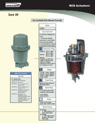
Modular Housings - Kube Engineering
Modular Housings - Kube Engineering
Modular Housings - Kube Engineering
- No tags were found...

You also want an ePaper? Increase the reach of your titles
YUMPU automatically turns print PDFs into web optimized ePapers that Google loves.
PRODUCT CATALOGModulesIsolation Amplifiers/TransmittersIsolation AmplifiersTransmittersIndicatorsProcess AnalyticsPortable MetersLaboratory MetersSensorsFittings
Selection MatrixInput Output Isolation Power supply0 ... 20 mA4 ... 20 mA0 ... 10 VBipolar0 ... (±)20 mA4 ... 20 mA0 ... (±)10 V0 ... 50 mAModel Products Other Page<strong>Modular</strong> <strong>Housings</strong> for Safe Areas and Zone 2Universal Isolation VariTrans ® P 27000 0 ... ±0.1 mA to 0 ... ±100 mA,0 ... ±20 mV to 0 ... ±200 VBroad-range1000 V5 kVpower supply 0.08 12.5 32Amplifiers VariTrans ® A 26000 Broad-range1000 V4 kVpower supply 0.1 12.5 40Broad-rangeIsolation Amplifiers VariTrans ® P 15000 1000 V4 kVpower supply 0.08 12.5 46for Standard SignalsVariTrans ® B 13000 600 V3.25 kV• • • 0.4 12.5 54VariTrans ® A 20000 300 V2.5 kV 0.2 6 62VariTrans ® B 10000 100 V510 V 0.4 6 68Standard Signal Doublers VariTrans ® A 20300 300 V1.5 kV 0.2 6 74Loop-powered17.5 /Isolation Amplifiers IsoTrans ® 41 0 ... 50 mA 500 V2.5 kV 0.02 22.5 80for Standard Signals17.5 /IsoTrans ® A 47 0 ... 50 mA 300 V2.5 kVLoop-powered0.2 22.5 88IsoTrans ® B 48 100 V510 VLoop-powered0.1 6 94IsoTrans ® A 20400 300 V2.5 kVLoop-powered0.1 6 100Broad-rangeHigh-Voltage Isolators VariTrans ® P 41000 ±60 mV to ±100 V 3600 V15 kVpower supply 0.1 22.5 106/ Isolation AmplifiersBroad-rangeVariTrans ® P 42000 ±100 V to ±3600 V 3600 V15 kVpower supply 0.3 45 114for Shunt ApplicationsBroad-rangeVariTrans ® P 43000 ±0.1 A to ±5 A 3600 V15 kVpower supply 0.3 67.5 120Repeater Power Supplies IsoAmp ® PWR A 20100 600 V2.5 kV 0.1 6 126IsoAmp ® PWR B 10116 300 V1.5 kV 0.2 6 132Universal PolyTrans ® P 32000 Resistance thermometers, strain gages, 300 V2.5 kV Broad-range 0.1 6 138Transmittersthermocouples, potentiometerspower supplyTemperature ThermoTrans ® P 32100 Resistance thermometers, 300 V2.5 kV Broad-range 0.1 6 150Transmittersthermocouplespower supplyThermoTrans ® A 20210 Resistance thermometers, 300 V2.5 kV 0.1 6 162thermocouplesStrain gage transmitters SensoTrans ® DMS P 32200 Strain gages 300 V2.5 kVBroad-rangepower supply 0.1 6 172SensoTrans ® DMS A 20220 Strain gages 300 V2.5 kV 0.1 6 180Resistance SensoTrans ® R P 32300 Potentiometers 300 V2.5 kVBroad-rangepower supply 0.1 6 188TransmittersSensoTrans ® R A 20230 Potentiometers 300 V2.5 kV 0.1 6 198AC/DC Transmitters IsoTrans ® 600 0 ... 5 A AC, 0 ... 400 V AC, 48 ... 63 Hz 400 V/600 VLoop-powered6 kV0.5•22.5 206<strong>Modular</strong> <strong>Housings</strong> for Hazardous AreasIsolation Amplifiers WG 20 1000 V4 kV 0.1 22.5 228for Standard SignalsLoop-Powered Isolators IsoTrans ® 36/37 3600 V10 kVLoop-powered0.2 22.5 220for Standard SignalsRepeater Power Supplies WG 20 1000 V4 kV 0.1 22.5 228WG 21 1000 V4.4 kV• • • 0.1 22.5 234Loop-Powered Supplies WG 25 1000 V10 kVLoop-powered0.1 22.5 240Temperature ThermoTrans ® 205 Resistance thermometers 1000 V4 kV• • • • 0.1 22.5 246TransmittersThermoTrans ® 206 Resistance thermometers 1000 V4 kV• • • • 0.1 22.5 246ThermoTrans ® 210 Thermocouples 1000 V4 kV• • • • 0.1 22.5 254ThermoTrans ® 211 Thermocouples 1000 V4 kV• • • • 0.1 22.5 254M12 Field <strong>Housings</strong>Isolation Amplifiers DuraTrans ® M12-A 20000 150 V1.5 kV 0.3 83.3 264for Standard SignalsLoop-Powered Isolators IsoTrans ® M12-A 200 300 V1.5 kVLoop-powered0.1 83.3 270Eurocards0 ... ±20 mV to 0 ... ±60 mV,Universal Isolation IsoAmp ® 11000 0 ... ±150 mV to 0 ... ±500 mV 1000 V4 kV• • 0.2 5 TE 278Amplifiers0 ... ±20 mV to 0 ... ±60 mV,IsoAmp ® 12000 0 ... ±150 mV to 0 ... ±500 mV 1000 V4 kV• • 0.2 5 TE 278Isolation Amplifiers IsoAmp ® 3000 1000 V4 kV 0.01 4/5 TE 286for Standard Signals IsoAmp ® 4000 1000 V4 kV 0.02 4/5 TE 286Standard-Signal IsoAmp ® EK 30/31 1000 V4 kV 0.1 4 TE 294MultipliersLoop-Powered Isolators IsoTrans ® 41 0 ... 50 mA 500 V2.5 kVLoop-powered0.02 4 TE 302IsoTrans ® 46 0 ... 50 mA 100 V510 VLoop-powered0.1 3 TE 308Modules0 ... ±20 mV to 0 ... ±60 mV,Universal Isolation IsoAmp ® 11000 0 ... ±150 mV to 0 ... ±500 mV 1000 V4 kV • 0.2 22.5 314Amplifiers0 ... ±20 mV to 0 ... ±60 mV,IsoAmp ® 12000 0 ... ±150 mV to 0 ... ±500 mV 1000 V4 kV • 0.2 22.5 314Isolation Amplifiers IsoAmp ® 3000 1000 V4 kV 0.01 22.5 320for Standard Signals IsoAmp ® 4000 1000 V4 kV 0.02 22.5 320Loop-Powered Isolators IsoTrans ® 41 0 ... 50 mA 500 V2.5 kVLoop-powered0.02 22.5 328IsoTrans ® 46 0 ... 50 mA 100 V4 kVLoop-powered0.1 22.5 334WorkingvoltageTest voltageAC 50 Hz24 V AC24 V DC110/115 V AC220/230 V ACOtherFault class[%]Width [mm] Covered / provided• Ordering alternatives2
KnickState of the ArtComponents from KnickIn the field of industrial galvanicisolation, Knick is the marketleader and pacesetter for technologicalchange. Components fromKnick are designed in a way thatthey not only operate reliablyunder normal conditions but alsoensure safe functioning underextreme operating conditions.The advantages are reflectedin every detail. The selection ofranges, for example, is alwayscalibrated in the Knick isolationamplifiers and transmitters. Thereis no need for complicated recalibration.Knick offers isolationamplifiers for particularly highworking voltages – up to 3600 VAC/DC – as well as devices forapplications where many signalsmust be processed in a smallspace. The 6-mm class includesisolation amplifiers and transmittersthat combine high flexibilityand precise signal transmissionwith safe galvanical isolation –up to 300 V AC/DC accordingto EN 61140.Constructive CompetenceThe conceptual design of newKnick devices focuses on the particularrequirements and demandsof the customers. Use of highqualitycomponents with longservice life is part of the basicdesign principles just as an intelligentcircuit design and the planningof safety margins betweenthe actual load and possiblemaximum load. Reliability is alsoachieved by reducing self-heatingand the resulting thermal loadby a suitable circuit design. Asa result, MTBF values of manyhundred years are obtained.Knick devices always orient themselvesto the customers’ economicobjectives such as minimizingoperational and consequentialcosts and increasing the productivity.A typical Knick module iseasy to configure, virtually maintenance-free,and provides abroad range of applications. Thefact that one module can be usedfor many applications significantlyreduces logistic costs and avoidseffort caused by wrong ordering.Certified QualityNumerous approvals prove thesuitability for extraordinaryrequirements and fields of application.The Knick range includesdevices with SIL, UL, CSA, FM,ATEX, KTA, and GL approvals.The company maintains a qualitymanagement system according toDIN EN ISO 9001 : 2000 and hasa confirmation of suitability ofthe quality assurance accordingto the KTA 1401 rule of theNuclear Safety Standards Commission.One result of the strictimplementation of the variousregulatory requirements is theproverbial long life and reliabilityof Knick isolators that is provedby a 5-year warranty.4
Isolation AmplifiersTransmittersIndicatorsProcess AnalyticsPortable MetersLaboratory MetersSensorsFittingsThe CompanyFor over 50 years, the nameKnick has been a by-word forexceptional quality in the manufactureof electronic measuringdevices. Back in 1945 thecompany’s founder, engineerUlrich Knick, started manufacturinghigh-precision zero-pointstabilizedDC amplifiers, layingthe foundation for the modulesproduct range. These amplifiersalso enabled the production ofreliable and precise pH meters.Today Knick develops and sells abroad range of devices for industrialanalog signal processing.About 50 % of the business volumeis generated with analoginterface products. The otherhalf applies to the field of liquidanalysis, where Knick’s highqualitymeasuring systems havebecome established in industryand laboratory.Innovative by TraditionToday, company policy still focuseson a high technical level anda highly innovative orientation.Every fourth employee worksin Research and Development.A large number of patents andlicensing agreements are theresult. Great emphasis is placedon Functional Safety, EMC, andexplosion protection, where thefirm has made a name for itselfwith its high level of expertise.The strategy of achieving businesssuccess through the provision ofoptimal technical solutions for demandingapplications has provedsuccessful and still promises stabilityand independence alongwith solid economic growth. Thecompany’s economic independencepermits long-term work ofthe Development departmentfocusing on innovation and sustainability– a necessary requirementfor today’s complex productsand systems but still not metby everyone. As a result, Knickcan provide products that reliablysolve the arising tasks and problemsand are a safe and longlastinginvestment.5
The Whole Range ofPerfection– Signals Over LongDistancesIf the measurement signal has along path, for example, to reachthe control room, potential differencescan occur between thepoint of measurement and thecontrol equipment causing considerablemeasurement errors.The electrical isolation completelyeliminates the effects of thesepotential differences thus rectifyingmeasurement errors. Isolationamplifiers and transmitters fromKnick always provide 3-port isolationso that a signal disturbanceis prevented in any case.– Signal AdaptationOne common task is the conversionof almost any measurementsignals to standard signals. TheVariTrans® series from Knickfeatures universal and standardsignalisolators with excellentcharacteristics in this area.– High Voltages in theMeasuring EnvironmentIf the signal being measured is ina high-voltage area (for example,power supplies for productionfacilities, buildings, railway facilities),it needs to be kept awayfrom the control technology,that is, it must be sufficientlyisolated. Standard products of theVariTrans® series have excellentcharacteristics for these applications:They are designed forworking voltages up to 1000 VAC/DC. The products of theP 40000 are even suitable forworking voltages up to 3600 VAC/DC. The routine tests areperformed with 15 kV AC.When measuring low signals athigh potentials, a high commonmode rejection (CMRR) must beensured since otherwise commonmode voltages can cause seriousmeasurement errors. The P 41100achieves a CMRR of 150 dB(DC/AC 50 Hz).– Signal AmplificationIf the power output of the signalsource is not sufficient, activeKnick isolators amplify the signalswithout distorting it due to interferingerrors. The current outputsof Knick products regularly supply10 or 12 V, i.e. 500 or 600 ohmsload at 20 mA. If that is not sufficient,the model A 20300 can beused to increase the maximumload to 1000 ohms (20 V) at20 mA.– Explosive MixturesSuitable hazardous area separationis required to connectmeasurement and control signalsbetween a hazardous area andthe control equipment. For theseapplications, the Knick rangefeatures devices which at thesame time provide galvanic isolationto prevent measurementerrors: 36A7, 37A7, WG 20.Repeater power supplies areavailable for the supply of 2-wiretransmitters in hazardous areas:WG 20/21/25.– Functional Safety(SIL)When developing new products,Knick takes account of their usein safety-related applications,i.e. they are to provide functionalsafety according to EN 61508.The PolyTrans®, ThermoTrans®,and SensoTrans® P 32000 transmittersare certified to SIL 2 bythe TÜV Rheinland, up to SIL 3can be achieved by redundantconfiguration.6
The CompanyChronology of Innovations|1945First zero-pointstabilizedmodulatedDC amplifier|1956First laboratorypH meter withzero-point-stabilizedKnick amplifier|1958First zero pointstabilized chopperlesspH amplifier|1960First transistorizedchopper amplifierfor measuring andcontrol engineering|1964First Knick amplifierfor hazardous-areaapplications|1964First DC transformer forpassive isolation inmeasuring and controlengineering|1979First microprocessorcontrolledlaboratory pHmeter with automaticelectrode calibration|1979First industrial pH meterwith digital display foron-site mounting inhazardous locationswith a Zone-0 input|1980First electrodelessconductivity measuringsystem for hazardousarea applicationswith PTB-testedsensor|1980First loop-powereddigital indicator formounting withinhazardous locations|1980First loop-powered DCtransformer for mountingwithin hazardouslocations|1985Firstretractable probecontroller for fully automatedpH measurement|1995First process analyzerfor simultaneousmeasurement of pHand conductivity inhazardous areas|1996First portable meterfor hazardous areaapplications withIP 66 protection|1997First process analyzerwith 20 ... 253 VAC/DC broad-rangepower supply|1998Firstterminal with electricalisolation|1999First isolation amplifierin 12.5 mm modularhousing with20 ... 253 V AC/DCbroad-range powersupply and calibratedrange selection|2000First product linefor liquid analysiswith PROFIBUS ® -PA interfaceand “Profile for ProcessControl Devices“|2004First IP68 isolationamplifier in M12 fieldhousing|2005First high-voltageisolator with broadrangepower supplyand 15 kV test voltage|2005Ceramat ®WA 160 –First remotecalibrationimmersionprobe|2006First universaltransmitter fortemperature, resistance,strain gages in 6-mmhousing with SILapproval|2006First openstandard of acontactlessplug-inconnectionfor intelligentelectrochemicalsensors|2006FirstO-ringsealedsensor lock-gate withlong service life andeasy on-sitemaintenance8
Isolation AmplifiersTransmittersIndicatorsProcess AnalyticsPortable MetersLaboratory MetersSensorsFittings|1965First zero-pointstabilizedindustrialpH transmitters forhazardous areaapplications|1967First portable pHmeter for hazardousareaapplications (5000operating hours withoutbattery replacement)|1969First compactdigital pH meter|1972First DCisolation amplifier fromKnick for activeisolation in measuringand controlengineering.|1973First portable pH meterwith digital display andautomatic sensorcontrol (2500 measurementswithout batteryreplacement)|1976First industrial pH transmitterfor applications inthe highest danger areaZone 0|1986First system-capableDC calibrators in theDM 2000 price range|1988Laboratory conductivitymeter with 4-electrodesensor and a new circuitprinciple that for thefirst time enablesmeasurements in the1 µS/cm ... 1000 mS/cmrange with a singlesensor|1991First loop-powereddigital indicator withEMC to NAMUR|1992First laboratory pHmeter with completeself-monitoring includingelectrode and EMCaccording to NAMUR|1992First analyzer line withEMC and user interfaceto NAMUR|1995First portable pH meterwith data logger andPC interface|2001First modular processanalyzer in hygienicstainless steel enclosure|2002First activeisolation amplifierwith 3-port isolationin 6 mm housing|2002First portable meter formeasuring dissolvedoxygen with flow-freesensors|2003First remotecalibrationprobe withmaintenance-freeceramic sealing|2003First measuring systemfor fully automatedpH measurement inhygienic locations|2003First repeater powersupply in 6 mmhousing|2006First portableanalyzer with watertight,hygienic stainlesssteel enclosure|2006First systemfor wirelesssignal transmission forpH, conductivity, andoxygen sensorsPROFIBUS ® is a registered trademark of the PROFIBUS Nutzerorganisation e. V. (PNO)9
Isolation AmplifiersTransmittersIndicatorsProcess AnalyticsPortable MetersLaboratory MetersSensorsFittingsDiscourseElectrical isolationin industrial measuringtechnologyIntroductionl––––––––––––––––––––––––––––––––––––––––––––––––––––––––––––––––––––––––––––––––––––––––––––––––––––––––– –––––––In industrial plants, the transmissionof measuring and controlsignals almost always requireselectrical isolation of the signalsbeing processed both for safetyreasons and in order to achieveoptimum signal quality(see Fig. 1).1000 V DCShunt 60 mVMAMeasurements at dangerouslyhigh voltages or in areas wherethere is an explosion hazard,different ground potentials(see Fig. 2) for example, inplant sections located a longway apart, as well as highcommon-mode voltages do notallow direct connection of themeasuring signals with otherdevices or assemblies. In thiscase, it is absolutely essential toelectrically isolate the transmittedsignals.Knick offers suitable componentsfor electrical isolation in variousdesigns to meet these requirements.Our range includes modularhousings, M12 field housingswith IP68 protection, solder-inmodules, and Eurocards.Depending on the model, theappropriate measuring signalsare also amplified or convertedto the standard values 10 V or20 mA. Voltages of a few mVup to 3000 V and currents ofa few µA up to 10 A can be0 V■ Fig. 1: Isolation of dangerous high voltagesShuntM1000 V DC60 mVP1I interferetransmitted or converted with ahigh level of accuracy.On the following pages the mostimportant technical terms usedin specifications and productdescriptions will be explainedV interfere■ Fig. 2: Avoiding interference caused by differences in potentialAP2to facilitate assessment andselection of suitable equipment.10
Electrical Isolation1. Isolators With / Without Power Supplyl––––––––––––––––––––––––––––––––––––––––––––––––––––––––––––––––––––––––––––––––––––––––––––––––––––––––– –––––––+Currentinput–Principle of Operation:It is obvious that transformersare the ideal components fortransmssion and electrical isolationof alternating quantities.Transformers are reliable, easyto produce and suitable for highworking or isolation voltages.However, they cannot transmitdirect voltage signals. The directvoltage signal is therefore firstconverted into an alternatingvoltage using an electronic chopper.This AC voltage is transmittedto the secondary circuit by aGenerator1:1transformer, where it is rectifiedin sync with the chopper frequency(see Fig. 3). The resultingDC voltage is then converted oramplified if necessary.+Currentoutput–Another principle of signal processingis used in the modern,switchable isolation amplifiersfrom the VariTrans® series.The input signal is converted intoa rectangular signal with a constantfrequency. The duty cycleof the rectangular voltage ischanged depending on the inputvoltages (pulse width modulation,PWM). The pulse widthmodulated rectangular signal istransmitted to the output sideelectrically isolated by means ofa tranformer. There it is reconvertedinto a voltage or currentusing a low-pass filter(see Fig. 4).■ Fig. 3: Schematic diagram of an isolator with transformer isolationPWM converter Transformer RC filterInputRC OutputDirect voltage Alternating voltage (PWM signal) Direct voltageVariable pulse widthThe transmission ratio of the isolationamplifier or transmitter iscontrolled by a microcontroller.The settings are made using DIPand rotary coding switches. Sincethese switches are not incorporatedin the negative feedbackof amplifier circuits, but insteadonly switch digital signals, theydo not carry currents and cannotcause any contact resistancefaults.■ Fig. 4: PWM principle: Pulse width modulationT11
Discourse++Currentinput–1:1+–Currentoutput–1.2 Loop-Powered Isolators(Passive Isolators)±Voltageinput (mV)0Generator■ Fig. 5: Schematic diagram of an active unipolar isolation amplifierGenerator■ Fig. 6: Schematic diagram of an active bipolar isolation amplifier±Voltageoutput0Electrical isolation of impressedcurrent signals does not necessarilyrequire active isolation amplifiers.Loop-powered isolatorscan often also be used withoutlimitations.The passive isolators from Knickdo not need a power supply, thepower is provided from the measurementsignal at the input terminalsas a voltage drop. The loadcapability of the input signal isreduced by the voltage requirementof the passive isolator.1.1 Isolation Amplifiers withExternal Power Supply(Active Isolators)Isolation amplifiers are thebest known type of devices forgalvanic isolation of measuringsignals. Often they are not onlyused as electrical isolators butalso as transmitters for signalconversion of voltages or currentsinto standardized 20 mA or10 V signals. When measurementsignals are transmitted 1:1, theyare also used to increase the signalload capacity. The loading ofthe input signal by the isolationamplifier is generally negligible.Isolation amplifiers generallyrequire an external power supply.Typical examples are the switchableVariTrans® P 27000 andP 15000 isolation amplifiers.Isolation Amplifiers forUnipolar Signal ProcessingIsolation amplifiers that are onlysuitable for transmitting unipolarmeasuring signals can be usedfor many applications, for example,for processing standard0/4 ... 20 mA and 0 ... 10 Vsignals. For the exact transmissioneven in the vicinity of zero, however,the control range of theKnick unipolar isolation amplifiersextends a few percent into thenegative range (see Fig. 5).Isolation Amplifiers forBipolar Signal ProcessingBipolar measurement signalsfrequently need to be processedwhen, for example, motor currentsare to be measured in bothdirections of rotation. Bipolar signalsare also processed when distancesare measured or for betterresolution of measurement signals.Knick also supplies differenttypes of bipolar isolation amplifiers,for example, the VariTrans®A 26000 for bipolar standardsignals (see Fig. 6).Passive isolators are suitablefor 1:1 transmission of unipolarcurrent signals. The suitabilityfor the respective applicationshould be checked taking theload capability of the inputsignal and output load intoconsideration.Example:A transmitter with 0 ... 20 mAsignal at the input of a looppoweredisolator can beloaded with maximally 10 V(IIN = 0...20 mA, VINmax = 10 V).The voltage drop VDROP of theloop-powered isolator is specifiedas 2.5 V. After VIN = VDROP + (IOUT· RL) the maximum output load isRLmax = (VINmax – VDROP) / 20 mA =375 ohms (see Fig. 7).12
Electrical IsolationIsolation AmplifiersTransmittersIndicatorsProcess AnalyticsPortable MetersLaboratory MetersSensorsFittingsTransmitter0 ... 20 mA,load10 VI I = 0 ... 20 mAV I = V intrins+ (I O · R L )I O = 0 ... 20 mAR L max =(10 V – V intrins )/20 mA=375 ØTransmitter0 ... 20 mAI I = I O = 0Loop-powered isolator■ Fig. 8: Loop-powered isolator with open outputTransmitterLoop-powered isolator■ Fig. 7: Circuit diagram for example 10 ... 20 mA I I = I OI OLoop-powered isolatorLoop-powered isolators do notallow signal amplification and arenot reactionless, i. e. the outputload acts directly on the inputsignal. As a result, a current cannotflow in the input circuit whenthe output is open (endlessresistance) (see Fig. 8).If temporary interruption of theoutput circuit could not be ruledout, a possible remedy was toconnect a suitable Zener diode inparallel with the isolator output.When the output circuit is open,the input current then flows viathe Zener diode in the output(see Fig. 9). In practice, thismethod often turned out to becomplicated and too error-prone.I O = 0Output open■ Fig. 9: Transmission of a measured signal over large distancesV = I O · R loadV max = < V ZInput voltage dropV I [V]54321,71Open output V I= 3 VWith Bürdenstop ® Without Bürdenstop ®0 0.5 1 1.3 1.5 20 25.0 50.0 65.0 75.0 100.0■ Fig. 10: Transfer function with Bürdenstop ®Knick’s Bürdenstop® (load stop)function solves that problem andthus considerably extends theapplication possibilities for looppoweredisolators. Here, thecurrent supplied at the primaryside is maintained independentlyfrom the output load. Any excessiveload increase at the output,such as caused by line breakageor inconstant loads includingcomplex impedances, can becompensated for. The IsoTrans®M12-A200 and IsoTrans® A20400 passive isolators are availablewith or without Bürdenstop®function. When the output load(e.g. input resistance of the controller)is up to 60 Ø, a passiveisolator with Bürdenstop® is thebest solution (see Fig. 10).The operating current requiredfor the Knick passive isolators isvery low. It is approx. 2 µA to100 µA depending on the modelwithout appearing as an additionaltransmission error. Passive isolatorsturn out to be particularlyadvantageous due to the simpleinstallation without additionalsupply lines. Loop-powered isolatorsare available in all housingversions.I I= I O= 20 mAV O [V] OutputvoltageR L [ohm] Load13
Discourse2. Transmittersl––––––––––––––––––––––––––––––––––––––––––––––––––––––––––––––––––––––––––––––––––––––––––––––––––––––––– –––––––Transmitters measure the signalsof sensors for physical quantitiessuch as temperature, path, angle,pressure, or force. They performa galvanic isolation and convertthe signals into standardized analogoutput signals: 0 ... 20 mA,4 ... 20 mA, or 0 ...10 V. Thesestandard signals can be transmittedto indicators, recorders and/or standardized controllers suchas DCS and can be used forcontrol applications.RTD 2-wireconnection1234RTD 3-wireconnection1234RTD 4-wireconnection■ Fig. 11: Connection of resistance thermometers1234RTD differentialmeasurement12342.1 Temperature Measurementwith Resistance Thermometersand ThermocouplesIn many fields of industrytemperature is an importantcontrolled variable. Here, themost important sensors areresistance thermometers andthermocouples.Resistance thermometersare highly accurate temperaturesensors with long-term stability.They measure temperatures byusing the temperature dependenceof the electric resistor.Resistance thermometers aremainly used to measure lowand medium temperatures, forexample, in air-conditioning,process engineering, and thefood industry.The most common resistancethermometers are Pt100, Pt1000,and Ni100. The first part of thedesignation represents the resistormaterial, the second partspecifies the resistance in ohmsT 1T 2■ Fig. 12: Thermocouple and reference junctionat 0 °C. Thus, for example,Pt100 designates a resistancethermometer made of platinumand having a resistance of100 ohms at 0 °C.The ThermoTrans® 205/206,A 20210, and P 32100 as wellas the PolyTrans® P 32000 transmittersallow connection of allcommon resistance thermometerseither with 2-, 3-, or4-wire connection (see Fig. 11).V TReference junctionThermocouplesThermocouples make use of theeffect named after T. J. Seebeckthat a junction of two dissimilarmetals produces an electricvoltage which is influenced bythe difference between the temperatureat the reference junctionand the temperature of the pointof measurement (see Fig. 12).When the thermoelectric voltageVT is measured using a suitabletransmitter and when the temperatureat the reference junctionis known, the temperature at thepoint of measurement can be14
Electrical IsolationIsolation AmplifiersTransmittersIndicatorsProcess AnalyticsPortable MetersLaboratory MetersSensorsFittingsdetermined from the characteristicof the thermocouple used. Thiscalculation is usually performedin the temperature transmitter.The temperature at the referencejunction can be measured oradjusted by thermostating.In practice, a measurement iseither taken “internally“, thenthe reference junction is withinthe temperature transmitter,or “externally“, then referencejunction and temperature sensorof the junction, e. g. a Pt100,are outside the transmitter.The voltage caused by thethermoelectric effect is very low –just a few microvolts per Kelvin.To obtain an interference-proofmeasurement signal, thermocouplesare preferrably used forhigh temperatures, for example,for measurements in ovens, smeltingplants, and plastic machines.A great number of metal pairswas tested for the production ofpractical thermocouples. Subsequentstandardization resulted ina manageable range of standardizedthermocouples with definedmaterial pairs. They cover themajority of all industrial temperaturemeasurement applications.The characteristics including permissibletolerances of thermocouplesare defined internationally inthe IEC 584-1 standard and inDIN 43710 which is not valid anymore and is to be applied onlyto old plants.IEC 584-1, EN 60584-1Type J Iron/Constantan(Fe/CuNi)Type T Copper/Constantan(Cu/CuNi)Type K Nickel Chromium/Nickel(NiCr/Ni)Type E Nickel Chromium/Constantan (NiCr/CuNi)Type N Nicrosil/Nisil (NiCrSi/NiSi)Type S Platinum Rhodium/Platinum (Pt10Rh/Pt)Type R Platinum Rhodium/Platinum (Pt13Rh/Pt)Type B Platinum Rhodium/Platinum (Pt30Rh/Pt6Rh)DIN 43710 (not valid anymore)Type L Iron/Constantan(Fe/CuNi)Type U (Cu/CuNi)High-temperature thermocouplessuch as W3Re/W25Re (tungsten3% rhenium/tungsten 25% rhenium)or W5Re/W26Re (tungsten5% rhenium/tungsten 26%rhenium) have not yet foundtheir way into a standard. Theircharacteristics are specified inASTM E 988-96.The Knick ThermoTrans®210/211, P 32100, andPolyTrans® P 32000 transmitterscan process the signals of allcommon thermocouples.15
DiscourseStrain gage full bridgeInternal supplyStrain gage full bridgeExternal supply112.2 Force Measurementswith Strain GagesForce, weight, torque, mechanicaltension, and the resulting parameterscan be measured by usingstrain gages. These make use ofthe effect that a change in lengthof a conductor due to strainresults in a proportional changein its electric resistance. In astrain gage transmitter thisresistance change is detected asa measure for the strain, force,etc. and then is converted to astandard signal for display andfurther processing.In practical industry applicationsthe filling weight of a container,for example, is measured by loadcells (force sensors, force transducers)which usually have integratedstrain gage full bridges.The bridge sensitivity is specifiedas signal level at the bridge outputin millivolts related to theexcitation voltage in volts, i.e. forexample 2 mV/V. When the sensitivityis known, e.g. from the calibrationcertificate of the sensormanufacturer, it is adjusted atthe transmitter. If only the nominalsensitivity is known, the actualsensitivity can be determinedby calibration with a definedmechanical load. Correspondingly,the zero point can be adjustedat the transmitter by using a tarefunction.The strain gage bridge can beconnected in 4-wire configuration(see Fig. 13). If the errorcaused by the current-carryingexcitation lines is to be reduced,a 6-wire configuration is used.■ Fig. 13: Supply of strain gagesHere, the bridge excitation voltageis measured through separatelines, virtually currentlessand therefore fault-free.In practice, also sensors that areequipped with 6 lines are operatedat 4-wire transmitters by combining2 excitation lines each.Alternatively, an external supplymay be used to take advantageof the 6-wire connection (seeFig. 13).The Knick SensoTrans® DMSA 20220 and P 32200 as well asthe PolyTrans® P 32000 transmittershave been designed for customarystrain gage sensors in afull-bridge arrangement. Sensitivityand zero point of calibratedsensors can be adjusted on thedevice by using rotary switchesor the Paraly® SW 111 parametersetting software. A tare functionto set the zero point can beactivated by a pushbutton onthe device or the software.Correspondingly, the sensorsensitivity can be calibrated ata defined load “at the push ofa button“.2342.3 Path and Angle Measurementswith PotentiometersAmong others, potentiometricsensors are used to detect linearor rotary movements. Potentiometricpath or angle sensors containresistance elements madeof conductive plastic material orwire-wound resistance elementswith movable sliding contacts.Potentiometer transmitters determinethe resistance ratio producedby the sliding contact sothat its position can be detectedand output as standard signal.Resistance transducers are usedfor setpoint specification in railvehicles, on ships, during industrialproduction, and in manyareas of machine and apparatusengineering. Resistive sensorsare used for detecting the actualvalue of actuators, for measuringdistances or thickness, and forvarious position measurementtasks. The Knick SensoTrans® RA 20230 and P 32300 as well asPolyTrans® P 32000 transmittersdetect potentiometers up to50 kohms in 3- or 4-wire configuration.The range of themovement to be mapped onthe range of the output signalcan easily be adjusted by usinga button on the device or theParaly® SW 111 software.23416
Electrical IsolationIsolation AmplifiersTransmittersIndicatorsProcess AnalyticsPortable MetersLaboratory MetersSensorsFittings3. Transmission Propertiesl––––––––––––––––––––––––––––––––––––––––––––––––––––––––––––––––––––––––––––––––––––––––––––––––––––––––– –––––––The properties required for signaltransmission are determined bydifferent factors. In addition tothe requirements regarding accuracyand speed of the signaltransmission, the input data ofthe following devices, the propertiesof the signal being transmittedand the ambient conditionsalso need to be taken intoaccount.0 ... 20 mA5 kmline length(e.g. 1 mm 2 )R lineApprox. 90 ØApprox. 90 ØR line■ Fig. 14: Transmission of a measured signal over largedistances3.1 Current or VoltageTransmissionThe initial criteria for selectingan isolation amplifier or a transmitterare the input signal to beprocessed and the output signalrequired. The output signal isgenerally determined by thefollowing devices such as controllers,indicators, DCS, PCS etc.,whereby many of these deviceshave either current or voltageinputs.If both possibilities are available,current signals should be preferredparticularly for longertransmission paths (see Fig. 14).Impressed current signals areconsiderably less sensitive tointerference than voltagesignals.3.2 Input ResistanceThe input resistances of modernisolation amplifiers are generallydimensioned in a way that theyare sufficiently high for voltageinputs and sufficiently low forcurrent inputs so that the signalbeing processed is practically notloaded. Only in a few cases (verylow voltage signals with a highsource resistance or low-loadcapability current signals) wouldthe input resistance be a selectioncriterion for isolation amplifiers.The input resistance of theVariTrans® P 41000 isolationamplifiers specially developed forshunt applications is, at approx.100 kØ, relatively low comparedwith other isolation amplifiers.However, for shunt applicationswith resistances in the mØ range,the resistance is still several timesto the power of ten higher thanrequired.17
Discourse3.2.1 Input Voltage DropIn various isolation amplifierswith a current input and in looppoweredisolators, the load onthe input signal is specified as avoltage drop and not as an inputresistance. This voltage drop isconstant during normal operationand is max. 500 mV inisolation amplifiers dependingon the model.In passive isolators, there is avoltage drop at the input resultingfrom the voltage requirementof the device plus the load voltageat the output. Before passiveisolators are used, the load capabilityof the measurement signaland the load connected to theisolator output should be known.An exception are the passiveisolators from Knick with Bürdenstop®(load stop) function: Thecurrent supplied at the primaryside is maintained independentof the output load.3.3 Output Load CapabilityThe load capability of voltageoutputs is generally indicated bythe maximum current. Almostall manufacturers specify a resistancevalue for the load capabilityat current outputs. This specificationdoes not indicate the loadcapability of the output currentsof Knick isolation amplifiersabsolutely correctly. Thereforethe output load capability is“traditionally“ given as a voltagevalue.A 20 mA current output with aload capability of 10 V can beloaded, for example, with 2 kØat 5 mA or 1 kØ at 10 mA. Thespecification of a maximum permissibleload voltage of 10 Vtherefore applies to every currentvalue, whereas 500 Ø wouldapply exclusively to 20 mA.3.4 Transmission AccuracyMany Knick isolation amplifiersstand out by extraordinarily lowtransmission errors so that theaccuracy requirements of virtuallyall industrial measurement tasksare exceeded. The long-termstability of Knick signal isolatorsensures maximum transmissionaccuracy even past the 5-yearwarranty granted for Knick isolationamplifiers and transmitters.3.4.1 Quality of MeasurementSignalsBest possible transmission of theinput signal is required not onlyfor applications in measurementengineering. Signal distortionsdue to change in polarity, overshootsin the case of signalchanges, extreme angles insquarewave transmission are therule in many isolation amplifiersavailable on the market. Theseundesirable properties are notimmediately visible to the user.They often do not becomenoticeable until inexplicableerrors occur during operation.In the cyclical, digital scanningof measured values, signaldistortions, for example, due toovershooting, can cause seriousmeasurement errors. For thisreason, Knick traditionally placesgreat emphasis on the accuratetransmission of signals in thedevelopment of its isolationamplifiers.18
Electrical IsolationIsolation AmplifiersTransmittersIndicatorsProcess AnalyticsPortable MetersLaboratory MetersSensorsFittings■ Fig. 15: Offset voltage■ Fig. 16: Offset current3.4.2 Residual RippleThe output signal of isolationamplifiers and transmitters isprincipally superimposed bylow interference voltages. Theseinterference voltages are caused,for example, by the chopper frequencyas well as by mains feedover.The amplitude of this interferencevoltage, referred to asresidual ripple, should be as lowas possible because otherwisemeasurement errors cannot beruled out – especially with lowmodulation.3.5 Temperature Coefficient(Gain Droop)The temperature coefficient orgain droop is a specification forchanges in gain caused by–+–+I offsetV offsetR NFR NFtemperature changes. Droop ratesare specified as a relative parameterin %/K or as an absolutevalue in nA/K or µA/K, for example.In absolute value specifications,you need to check whetherthe TC refers to the input or theoutput.Examples:– The temperature coefficientat the output of an isolationamplifier is max. 10 nA/K. Achange in temperature of 20 Kcauses a change in the outputcurrent of 20 · 10 nA = 200 nA.– The TC of a transmitter is0.0025 %/K. A temperaturechange of 20 K causes a gainchange of 20 · 0.0025 % =0.05 %.3.6 Offset Voltage,Offset CurrentIn real amplifiers,the output variable isnot exactly zero evenwhen the input signalis zero. The inputoffset voltage of anamplifier is by definitionthe voltage thatneeds to be appliedto the input in orderfor the output variableto become zero.It therefore acts as aninput voltage or anadditional voltageacting in series withthe input signal (see Fig. 15).The input offset current of anamplifier also acts as an additionalinput signal (see Fig. 16). Inamplifiers with a voltage input,the offset current causes a voltagedrop at the internal resistorof a signal voltage source that isadded to the input signal.The offset voltage and offset currentare so low in Knick isolationamplifiers that they are negligiblefor normal applications. Offsetinfluences should only be consideredfor very special applicationssuch as the 1:1 transmission ofvery small measurement signalsor the transmission or amplificationof very high-resistancesignals. The polarity of offsetparameters depends on thedevice and therefore is givenas an absolute value withoutplus or minus sign.19
Discourse3.7 Cutoff FrequencyIsolation amplifiers and transmittersare principally designed forthe transmission or amplificationof direct voltage signals. Inorder to be able to transmit fastchanges in the measured valuealmost without delay, Knickdevices can also transmit alternatingquantities to a certainextent. The upper cutoff frequencyis up to approx. 12 kHz forsinusoidal signals dependingon the model.As an upper limit frequency, asis common in electronics andtelecommunications, the frequencyis defined at whichthe gain is attenuated by 3 dBcompared to the DC gain, i.e.it corresponds to approx. 71 %DC gain (see Fig. 17).0 Hz (DC)f CO3 dBf■ Fig. 17: Frequency response of an isolation amplifierInput = 0 VOutput ≠ 0 VV CM■ Fig. 18: Common-mode modulation3.8 Common-Mode BehaviorIf the same voltage Vcm is appliedto ground at both inputs of asymmetrical amplifier, the inputvoltage remains Vin = 0. Thisoperating mode is called common-modemodulation. In anideally symmetrical amplifier, theoutput voltage Vout would alsoremain at 0. However, this is notthe case in real amplifiers, i. e.a voltage deviating from 0 willappear at the output (see Fig. 18).A common-mode modulationalways exists when the signalvoltage is not at ground potential,i.e. when there is a potentialdifference between the (two)input lines and the ground, forexample, when measuring voltagesacross a shunt lying at ahigh potential against ground.Common-mode voltages canalso occur as common-modeinterferences, for example,during switching processes,due to stray pickup in the signallines or due to compensatingcurrents.The ratio between an appliedcommon-mode voltage and theresulting output voltage is knownas common-mode gain. However,in practice, the deviation fromthe ideal common-mode behaviorof an amplifier, specified as common-moderejection, is of greaterinterest. The common-moderejection ratio CMRR is definedas the ratio of differential-modeto common-mode gain or as thelogarithmic ratio of an appliedcommon-mode voltage Vcm toa signal voltage Vd that wouldproduce the same output signal:CMRR = 20 · log (Vcm/Vd) [dB].20
Discourse5. Electrical Safetyl––––––––––––––––––––––––––––––––––––––––––––––––––––––––––––––––––––––––––––––––––––––––––––––––––––––––– –––––––5.1 Working VoltageAn important parameter whenselecting a suitable isolationamplifier or transmitter is thepermitted working voltage.It indicates the permitted potentialdifference between the differentcircuits (input, output, andsupply circuits) (see Fig. 21).ShuntM1000 V DC1000 A /60 mVWorking voltage1000 VAThe permitted working voltageof an isolation amplifier maydiffer between the differentcircuits. The highest of the specifiedworking voltages generallyapplies across the input andoutput and across the inputand power supply. The permittedworking voltage across the outputand power supply can belower. The permitted workingvoltages for Knick isolationamplifiers are up to approx.3600 V AC/DC depending onthe model.■ Fig. 21: Illustration of the purpose of working voltageThe requirements for the workingvoltages are defined in EN 61010Part 1. It should be noted thatthe permissible working voltageis not only determined by thedielectric strength of the solidinsulations used for the isolatingcomponents, but also by constructionalfeatures such as clearanceand creepage distances aswell as by external influences,particularly the pollution degree(environment-related, possiblecontamination) and the overvoltagecategory (value of superimposedpulse voltages).Pollution DegreesPollution Degree 1There is no or only dry, nonconductivecontamination, forexample, in air-conditioned orclean, dry rooms.Pollution Degree 2There is only non-conductivecontamination. Occasional, temporaryconductivity due to condensationcan be expected, forexample, in laboratories, precisionmechanics workshops, testdepartments, and salesrooms.Pollution Degree 3There is conductive contaminationor dry, non-conductivecontamination that becomesconductive due to expectedcondensation, for example, inrooms at industrial plants, agriculturalplants, unheated warehouserooms, and boiler rooms.Pollution Degree 4The contamination leads topermanent conductivity, forexample, due to conductivedust, rain, or snow; in openrooms or outdoors.24
Electrical IsolationIsolation AmplifiersTransmittersIndicatorsProcess AnalyticsPortable MetersLaboratory MetersSensorsFittingsOvervoltage CategoriesOvervoltage Category INo occurance of overvoltageor protection by surge arrestersor filters.Overvoltage Category IISystems with switching processes,but without lightning strikes,for example, in private households.Overvoltage Category IIISystems without lightning strikes,connection of the device nearerto the power supply connectionthan the loads and/or specialrequirements for safety andavailability of the device.Overvoltage Category IVPlants with lightening strikes.5.2 Test VoltageThe dielectric strength of theinsulation material used for theisolating components is manytimes greater than the workingvoltage permitted for the device.Therefore the test voltage withwhich each device is tested isspecified additionally for isolatingdevices. This ensures that thespecified limit values for theworking voltage apply to eachdevice.The test voltage is also used occasionallyas a parameter for thedielectric strength instead of theworking voltage. This then needsto be a certain factor higher thanthe maximum possible potentialdifference between the circuits tobe isolated according to the directivefor the specific application.The test voltage for Knick isolationamplifiers is up to 15 kV AC.5.3 Safe IsolationThe term “Safe Isolation“ isdefined in EN 61140. This basicsafety standard describes protectivemeasures against electricshocks and thus defines therequirements to be met by electricalisolation between electriccircuits. “Safe Isolation“ refers toan isolation system which is characterizedby basic protection andadditional precautions (additionalinsulation or protective shielding)or by equivalent insulation (reinforcedinsulation according toEN 61010-1). It has the aim toprotect persons against electricshock. This particularly high levelof safety must be ensured byconstructive measures such asappropriate clearance and creepagedistances as well as by theinsulation properties of the internalisolating components. Thatmeans that the requirements ofthe basic safety standard have adirect effect on the isolatordesign.25
DiscourseHazardousAreaTransmitter0 ... 20 mASafe AreaInputOutputIsoTrans ® 36 A7150 ... 20 mA26 R LThe specification “Safe Isolation“always includes the indication ofa working voltage up to whichthe “Safe Isolation“ is guaranteed.All new isolation amplifiersand transmitters developed byKnick meet the requirements ofEN 61140 regarding “SafeIsolation“.5.4 ApprovalsOn an international basis,often the US and Canadian ULapprovals (Underwriter Laboratories)and CSA (CanadianStandards Association) or theircombination CUL are demanded.Many Knick isolation amplifiershave proven in strict approvaltests that they fulfil the respectiverequirements for electricalsafety and fire protection.The GL approval (GermanischerLloyd) confirms the high loadcapability of many Knick isolationamplifiers. It permits the use onships and for offshore applications,for example.The “Kerntechnische Ausschuß“(KTA – Nuclear Safety StandardsCommission) in the GermanFederal Office for RadiationProtection issues nuclear safetystandards that are identifiedby the letters KTA. Knick offersisolation amplifiers with KTA3503 (3507) approval forapplication in nuclear powerstations.Power supply■ Fig. 22: Coupling of intrinsically safe and non-intrinsically safe circuitswith the IsoTrans ® 36 A7 passive isolator5.5 Hazardous AreaSeparationWhen electrical equipment(including electrical and electronicmeasuring devices) is usedin potentially explosive atmospheres,it must be sure that thesedevices cannot ignite any explosivegas-air mixtures even whenthey malfunction. The possibletypes of protection include the“intrinsic safety“ that ensuresthat the intrinsically safe circuitsin the respective device cannotgenerate ignitable sparks evenin the event of a malfunction.In practice, an isolated solutionwith intrinsically safe circuits ishardly ever possible, i. e. couplingwith non-intrinsically safe circuitsis necessary for signal processing.The direct link would cancel outthe intrinsic safety and is thereforenot permitted. Knick suppliessuitable isolation amplifierswith or without separate powersupply for coupling the correspondingcircuits and providingboth electrical isolation andhazardous area separationbetween intrinsically safe andnon-intrinsically safe circuits(see Fig. 22).The devices supplied by Knickwith “intrinsic safety“ type ofprotection comply with the94/9/EC directive. This directiveis generally referred to as ATEX.In Europe equipment for explosionprotected areas usually isunderstood as equipment of Category1 or 2, that is for Zone 0 or1. Equipment of Category 3 – forapplication in Zone 2 – is becomingincreasingly important. Zone2 is a place in which an explosiveatmosphere consisting of a mixtureof air with dangerous substancesin the form of gas, vapor,or mist is not likely to occur inthe normal operation and if itdoes occur, will persist for a shortperiod only. Normal operationmeans the situation when installationsand devices are usedwithin their design parameters.Such installations and devicesensure the required safety level.Zone 2 may include, amongothers:– Areas surrounding Zones 0 or 1– Areas around flange connectionswith ordinary flat gasketsin pipes in enclosed spaces.The Series P32x00 and A202x0transmitters are intended foroperation in ATEX Zone 2(EN 60079-15) or Class 1, Div 2 /Zone 2 (UL 1604).26
Electrical IsolationIsolation AmplifiersTransmittersIndicatorsProcess AnalyticsPortable MetersLaboratory MetersSensorsFittings6. Functional Safetyl––––––––––––––––––––––––––––––––––––––––––––––––––––––––––––––––––––––––––––––––––––––––––––––––––––––––– –––––––6.1 Functional Safety(SIL)6.1.1 Functional SafetyThe breakdown and malfunctionof process plants and machinescan lead to personal, environmental,and material risks. Theeffects of damage and the probabilitiesof occurrence determinethe measures required for minimizingrisk through fault prevention,fault detection, and faultcontrol. The international safetystandard IEC/EN 61508 definesthe requirements for safetyrelatedsystems in a plant. Thesafety-related systems examinedin this standard are based onelectrical, electronic, and programmableelectronic technology.The term “functional safety“describes the part of overallplant safety which depends onthe correct functioning of thesafety-related systems.6.1.2 Safety Integrity Level(SIL)The IEC/EN 61508 uses a riskbasedapproach to determinethe safety integrity requirements.Each safety function is assigned asafety integrity level which specifiesthe risk reduction requiredfor each determined hazardousevent. The remaining residual riskis determined by calculating theprobability of failure of all componentsinvolved in the safetycircuit and their interconnection.There are 4 different safety levels:from SIL 1 for a low risk to SIL 4for a very high risk. Two SIL categoriesare distinguished accordingto the respective application:– For safety functions which areactivated when required (ondemand), the probability offailure to perform the functionon demand is specified(Low Demand Mode).– For safety functions whichare continuously active, theprobability of a hazardousfailure is specified for a givenperiod of time (per hour)(High Demand Mode).6.1.3 Device CertificationThe IEC/EN 61508 covers safetyrelatedsystems over the entiresafety lifecycle, i. e. from conceptionto shutdown or deinstallation.In the product development,particular importance isplaced on verification. In a seriesof analyses and tests it must beproved that a device complieswith the safety integrity requirementfor a certain safety chain.The results form the basis forcertification by an independentbody. The PolyTrans® P 32000,ThermoTrans® P 32100,SensoTrans® DMS P 32200,and SensoTrans® P 32300 transmittersare certified to SIL 2 bythe TÜV Rheinland. With redundantconfiguration they canachieve SIL 3.27
Discourse6.2 Surge WithstandIn industrial plants, transientovervoltages with rise speeds ofseveral 1000 V/µs occur in particulardue to switching processes.This kind of overvoltage can leadto damage or destruction ofsensitive electronic components.Newly developed Knick isolationamplifiers are surge proof accordingto IEC 255-4. Both the individualcircuits (input, output, supply)and the isolation betweenthe circuits are protected againstbeing destroyed by temporaryovervoltages. The test is madewith positive and negative pulsesof 5 kV with 1.2 or 50 µs pulseduration.6.3 ElectromagneticCompatibility (EMC)The term “electromagnetic compatibility“refers to the ability ofelectrical and electronic equipmentto function satisfactorily inits electromagnetic environmentwithout introducing intolerableelectromagnetic disturbances toother equipment in that environment.The increasing use of allkinds of devices that couldemit interference, the constantlyincreasing use of modern microelectronicsin all fields of industryand the interaction of powerelectronics and microelectronicscalls for measures protectingagainst mutual influence.Electromagnetic interferencecan cause malfunctions and evencomplete failure of unprotectedelectronic devices. The constantlylower energy requirement ofmicroelectronics componentsand simultaneously increasingprocessing speeds lead toincreased sensitivity to electromagneticinterference.Within the European Union thelimit values to be observed withregard to EMC, in addition toother requirements to be met,are regulated by harmonizedstandards and laws. The Low-Voltage Directive and the EMCstandards are relevant for isolationamplifiers. The CE certificationof Knick products confirmsconformity with the respectivedirectives.28
Electrical IsolationIsolation AmplifiersTransmittersIndicatorsProcess AnalyticsPortable MetersLaboratory MetersSensorsFittings6.4 Protection againstMechanical LoadsMechanical loads, for example,caused by shaking or vibrations,are often inevitable in industrialplants, in vehicles, on ships etc.However, the operating safety ofelectrical and electronic componentsalso needs to be ensuredin these environments.The VariTrans® P 27000,A 26000, P 15000, B 13000,and A 20400 were thereforetested according to the rules ofGermanischer Lloyd and havebeen granted the GL approvalfor environmental category D:applications with increased heatdevelopment and at increasedvibration levels, for example,devices for mounting on combustionengines or compressors.6.5 IP 68 ProtectionWith the M12 field housings,Knick has now presented a newseries that considerably simplifiesdecentralization in the field ofanalog signal transmission. TheDuraTrans® M12 and IsoTrans®M12 devices are protected toIP68 and are installed withoutan enclosure or additional protectivecase directly on themachine. Even harsh ambientconditions are no problem.The housing material PBT(polybutylene terephthalate) isextremely resistant to minerallubricants and alcohols andcomplies with flame class V-0according to UL 94.Vacuum encapsulation reliablyprotects the electronics againstenvironmental influences. Forconnection, the tried and testedM12 circular connectors areused.6.6 ReliabilityKnick gives a 5-year warrantyon electrical isolation modules.Due to their recognized qualityand reliability, they are widespreadin industrial measuringand control engineering acrossthe world.The Knick quality managementhas been certified accordingto ISO 9001 for all areas ofthe company and has also contributedto Knick being certifiedaccording to KTA 1401 as a recognizedsupplier of isolationamplifiers for use in nuclearpower stations since 1994. Othercorresponding certifications havealso been awarded for productsused in the safety-related areasof nuclear power stations.Intelligent circuits with minimaluse of components allow reliabilityvalues that were previouslyconsidered to be impossible –for example, the MTBF (MeanTime Between Failures) of thenew VariTrans® B 10000 standard-signalisolator is 440 years.The quality of all Knick productsis ensured by computer-supportedindividual testing. For theelectrical isolation modules, thismeans that each individual deviceis checked again for perfect functioningand compliance with alldata after the functional test,adjustment, encapsulation wherenecessary, and high-voltage test.Only then is the device approvedfor delivery.29
Discourse7. Space Requirementl––––––––––––––––––––––––––––––––––––––––––––––––––––––––––––––––––––––––––––––––––––––––––––––––––––––––– –––––––When selecting a device, thehousing width is an importantcriterion since the available spaceis often limited. With the 6-mmclass introduced by Knick, theminimum housing width hasbeen achieved. Knick initiatedthis technological change in2001 by introducing theVariTrans® B 10000 standardsignalisolators.The Knick isolation amplifiersin wider modular housings meethigher demands, for exampleconcerning isolation or mechanicalproperties.In this catalog the devices ofthe 6-mm class are identifiedby a corresponding logo.In the meantime Knick has complementedthe product line ofthe 6-mm class with devicesproviding safe isolation, signaldoublers or standard-signal isolatorswith high output load,passive standard-signal isolators,repeater power supplies withsignal conversion as well asuniversal transmitters and temperaturetransmitters.Particular attention has beenpaid to energy efficiency. Powerloss and the resulting self-heatingare strongly reduced resultingin very high reliability and longservice life.In spite of the reduced space,the 6-mm class provides true3-port isolation between input,output, and power supply to preventparasitic voltages. Safe Isolationaccording to EN 61140 forworking voltages up to 300 VAC/DC guarantees best possibleprotection of personnel andequipment. The test voltageis up to 2.5 kV AC. The 6-mmproducts are UL and CSAapproved for application inNorth America.30
<strong>Modular</strong> <strong>Housings</strong>Isolation AmplifiersTransmittersIndicatorsProcess AnalyticsPortable MetersLaboratory MetersSensorsFittings<strong>Modular</strong> <strong>Housings</strong> for Safe Areas and Zone 2Pagel––––––––––––––––––––––––––––––––––––––––––––––––––––––––––––––––––––––––––––––––––––––––––––––––––––––––––––––––––Universal Isolation Amplifiers VariTrans® P 27000 32VariTrans® A 26000 40l––––––––––––––––––––––––––––––––––––––––––––––––––––––––––––––––––––––––––––––––––––––––––––––––––––––––––––––––––Standard-Signal Isolators VariTrans® P 15000 46VariTrans® B 13000 54VariTrans® A 20000 62VariTrans® B 10000 68l––––––––––––––––––––––––––––––––––––––––––––––––––––––––––––––––––––––––––––––––––––––––––––––––––––––––––––––––––Standard-Signal Doubler VariTrans® A 20300 74l––––––––––––––––––––––––––––––––––––––––––––––––––––––––––––––––––––––––––––––––––––––––––––––––––––––––––––––––––Loop-Powered Isolators IsoTrans® 41 80for Standard Signals IsoTrans® A 47 88IsoTrans® B 48 94IsoTrans® A 20400 100l––––––––––––––––––––––––––––––––––––––––––––––––––––––––––––––––––––––––––––––––––––––––––––––––––––––––––––––––––High-Voltage Isolators / VariTrans® P 41000 106Isolation Amplifiers for Shunt Applications VariTrans® P 42000 114VariTrans® P 43000 120l––––––––––––––––––––––––––––––––––––––––––––––––––––––––––––––––––––––––––––––––––––––––––––––––––––––––––––––––––Isolated Supplies IsoAmp® PWR A 20100 126IsoAmp® PWR B 10116 132l––––––––––––––––––––––––––––––––––––––––––––––––––––––––––––––––––––––––––––––––––––––––––––––––––––––––––––––––––Universal Transmitters PolyTrans® P 32000 138l––––––––––––––––––––––––––––––––––––––––––––––––––––––––––––––––––––––––––––––––––––––––––––––––––––––––––––––––––Temperature Transmitters ThermoTrans® P 32100 150ThermoTrans® A 20210 162l––––––––––––––––––––––––––––––––––––––––––––––––––––––––––––––––––––––––––––––––––––––––––––––––––––––––––––––––––Strain Gage Transmitters SensoTrans® DMS P 32200 172SensoTrans® DMS A 20220 180l––––––––––––––––––––––––––––––––––––––––––––––––––––––––––––––––––––––––––––––––––––––––––––––––––––––––––––––––––Resistance Transmitters SensoTrans® R P 32300 188SensoTrans® R A 20230 198l––––––––––––––––––––––––––––––––––––––––––––––––––––––––––––––––––––––––––––––––––––––––––––––––––––––––––––––––––AC/DC Transmitters IsoTrans® 600 206l––––––––––––––––––––––––––––––––––––––––––––––––––––––––––––––––––––––––––––––––––––––––––––––––––––––––––––––––––Power Supplies IsoPower® A 20900 212<strong>Modular</strong> <strong>Housings</strong>31
<strong>Modular</strong> <strong>Housings</strong>VariTrans ® P 27000The “Multimeter” amongthe isolators. With 480switchable calibratedranges and broad-rangepower supply.The TaskA wide range of measuring signalsneed to be galvanically isolatedand converted into standardsignals. This applies to any inputsignals in the range ±20 mV to±200 V and from ±0.1 mA to±100 mA.The ProblemThe variety of tasks results in alarge number of different devices.The SolutionThe calibrated switching of theinput and output ranges usingDIP switches allow the KnickVariTrans® P 27000 professionaluniversal isolators to be usedwithout complicated readjustment.As switchover occurs withoutexpensive and unreliableequipment, the devices can alsobe easily configured on site.The broad-range power supplyfor all common supply voltagesfrom 20 to 253 V AC/DC offersmaximum flexibility.To make setting the requiredinput and output ranges simpleand user friendly, we supply afree software tool called VariSoft®to support the user. VariSoft®shows you the correct DIP switchposition when you enter therequired input and output rangesand it has a print option for yourdocumentation.You can download VariSoft® freeof charge from our website.The HousingAt just 12.5 mm wide, the modularhousing with pluggable screwterminals allows simple and fastassembly and prewiring of enclosures.<strong>Housings</strong> with fixed screwterminals are also available forextremely high mechanical loads.The easy-to-open housing allowssimple configuration of the inputand output ranges and providesgood protection against contactand unintentional adjustment.The AdvantagesThe analog transmission of themeasurement signal with transformerpotential isolation and thedigitally controlled range selectionguarantee almost perfect signaltransmission:– Gain error only 0.08 %– Excellent pulse formation– Extremely low residual ripple– Maximum long-term stabilityand reliabilityThe TechnologyA microcontroller monitors thecontrol element settings and controlsthe calibrated range selection.Interference to the signaltransmission – for example, dueto contact resistance in the rangeswitch – is thus ruled out.Thanks to the VariPower® powersupply, the devices can be usedall over the world with almostany power supply. The extremelylow power consumption and therelated minimal self-heating significantlyincrease reliability. Theconsequence: a 5-year warranty.Warranty5 years!Defects occurring within 5 yearsfrom delivery are remedied free ofcharge at our works (carriage andinsurance paid by sender).32
Universal Isolation AmplifiersIsolation AmplifiersTransmittersIndicatorsProcess AnalyticsPortable MetersLaboratory MetersSensorsFittings■ The FactsFlexible and highly accurateCalibrated range selection withoutcomplicated readjustmentVariPower®broad-range power supply,20 … 253 V AC/DCMaximum reliabilityNo repair and failure costs5-year warrantyExtremely compact design12.5 mm modular housing,up to 80 active isolators permeter of mounting railFast and easy configurationHousing simple to openPluggable screw terminalsSimple, time-saving assembly andprewiring of enclosures3-port isolationProtection against incorrectmeasurements or damageMaximum accuracyIndividual test reportfollowing EN 10204 2.3Safe isolationaccording to EN 61140.Protection against high voltages(for example, with shunt measurementsat high potentials or in3-phase systems).33
<strong>Modular</strong> <strong>Housings</strong>VariTrans ® P 27000■ Product LineDevices Order No. Order No.l–––––––––––––––––––––––––– l–––––––––––––––––––––––––––––––––––––––––––––––––––––––––––––––––––––––––––––––– ––With pluggable With fixedInput Output screw terminal screw terminall–––––––––––––––––––––––––– l––––––––––––––––––––––––––––––––––––––––––––––––––––––––––––––––––––––––––––––– –––VariTrans® P 27000 0 ... ±20 mV/200 V 0 ... 20 mA P 27000 H1 P 27000 F1Input and output 0 ... ±0.1 mA/100 mA 4 ... 20 mAadjustable0 ... 10 V0 ... ±10 V0 ... ± 20 mAl–––––––––––––––––––––––––– l–––––––––––––––––––––––––––––––––––––––––––––––––––––––––––––––––––––––––––––––– ––VariTrans® P 27000 0 ... ± 20 mA 0 ... ± 20 mA P 27016 H1 P 27016 F1Fixed setting 0 ... ± 20 mA 0 ... ±10 V P 27018 H1 P 27018 F10 ... ±60 mV 0 ... ± 20 mA P 27056 H1 P 27056 F10 ... 60 mV 4 ... 20 mA P 27057 H1 P 27057 F10 ... ±60 mV 0 ... ±10 V P 27058 H1 P 27058 F10 ... ±150 mV 0 ... ± 20 mA P 27066 H1 P 27066 F10 ... 150 mV 4 ... 20 mA P 27067 H1 P 27067 F10 ... ±150 mV 0 ... ±10 V P 27068 H1 P 27068 F10 ... ±300 mV 0 ... ± 20 mA P 27076 H1 P 27076 F10 ... 300 mV 4 ... 20 mA P 27077 H1 P 27077 F10 ... ±300 mV 0 ... ±10 V P 27078 H1 P 27078 F10 ... ±500 mV 0 ... ± 20 mA P 27086 H1 P 27086 F10 ... 500 mV 4 ... 20 mA P 27087 H1 P 27087 F10 ... ±500 mV 0 ... ±10 V P 27088 H1 P 27088 F10 ... ±1 V 0 ... ± 20 mA P 27096 H1 P 27096 F10 ... 1 V 4 ... 20 mA P 27097 H1 P 27097 F10 ... ±1 V 0 ... ±10 V P 27098 H1 P 27098 F10 ... ±10 V 0 ... ± 20 mA P 27036 H1 P 27036 F10 ... ±10 V 0 ... ±10 V P 27038 H1 P 27038 F1l–––––––––––––––––––––––––– l–––––––––––––––––––––––––––––––––––––––––––––––––––––––––––––––––––––––––––––––– ––VariTrans® P 27000 P 27000 H1-nnnn P 27000 F1-nnnnFixed settingto customer requirementPower supplyl––––––––––––––––––––––––––––––––––––––––––––––––––––––––––––––––––––––––––––––––––––––––––––––––––––––––––––– –––20 ... 253 V AC/DC34
Universal Isolation AmplifiersIsolation AmplifiersTransmittersIndicatorsProcess AnalyticsPortable MetersLaboratory MetersSensorsFittings■ SpecificationsInput datal–––––––––––––––––––––––––– l–––––––––––––––––––––––––––––––––––––––––––––––––––––––––––––––––––––––––––––––––––Inputs P 27000 H1/F1: Factory setting ±10 VVoltageConfigurable from 20 mV ... 200 V and switchable in calibratedsteps: 60 mV, 100 mV, 150 mV, 300 mV, 500 mV, 1 V, 5 V,10 V, 100 V, unipolar/bipolarCurrentConfigurable from 0.1 mA ... 100 mA and switchable incalibrated steps: 1 mA, 5 mA, 10 mA, 20 mA, 50 mA,unpolar/bipolar and 4 … 20 mA 1)l–––––––––––––––––––––––––– l–––––––––––––––––––––––––––––––––––––––––––––––––––––––––––––––––––––––––––––––––––Input resistance Current input Ranges ≤ 5 mA approx. 100 ohmsRanges > 5 mA approx. 5 ohmsVoltage inputapprox. 1 Mohml–––––––––––––––––––––––––– l–––––––––––––––––––––––––––––––––––––––––––––––––––––––––––––––––––––––––––––––––––Overload Current input Ranges ≤ 5 mA ≤ 100 mARanges > 5 mA ≤ 300 mAVoltage input Ranges ≤ 500 mV limited by suppressor diode 36 V,max. permitted continuous current ≤ 20 mARanges > 500 mV limited by suppressor diode 250 V,max. permitted continuous current ≤ 3 mAOutput datal––––––––––––––––––––––––––Outputl––––––––––––––––––––––––––Offsetl–––––––––––––––––––––––––––––––––––––––––––––––––––––––––––––––––––––––––––––––––––P 27000 H1/F1: factory setting ±10 V20 mA, 5 V, 10 V unipolar/bipolar and4 ... 20 mA, 1 ... 5 V and 2 ... 10 V, calibrated selectionl––––––––––––––––––––––––––––––––––––––––––––––––––––––––––––––––––––––––––––––––––––100 %, –50 %, 0 %, 50 %, 100 % of span of the selected output rangecalibrated selectionl–––––––––––––––––––––––––––––––––––––––––––––––––––––––––––––––––––––––––––––––––––l––––––––––––––––––––––––––Load With output current ≤ 12 V (600 ohms at 20 mA)With output voltage ≤ 10 mA (1 kohm at 10 V) 2)l––––––––––––––––––––––––––Offsetl––––––––––––––––––––––––––Residual ripplel–––––––––––––––––––––––––––––––––––––––––––––––––––––––––––––––––––––––––––––––––––20 µA or 10 mVl–––––––––––––––––––––––––––––––––––––––––––––––––––––––––––––––––––––––––––––––––––< 10 mVrmsTransmission behaviorl–––––––––––––––––––––––––– l–––––––––––––––––––––––––––––––––––––––––––––––––––––––––––––––––––––––––––––––––––Adjustment rangeof ZERO potentiometer ±25 % span of selected output rangel–––––––––––––––––––––––––– l–––––––––––––––––––––––––––––––––––––––––––––––––––––––––––––––––––––––––––––––––––Adjustment rangeof SPAN potentiometer 0.33 … 3.30 x end value of selected input range (max. Vin = 200 V)l–––––––––––––––––––––––––– l–––––––––––––––––––––––––––––––––––––––––––––––––––––––––––––––––––––––––––––––––––Gain error< 0.08 % meas. val. (DC)l–––––––––––––––––––––––––– l–––––––––––––––––––––––––––––––––––––––––––––––––––––––––––––––––––––––––––––––––––Cut-off frequencyP 27000 H1/F1: > 10 kHz, < 10 Hz, switchable –3 dB, fixed-setting models > 10 kHz, –3 dBl–––––––––––––––––––––––––– l–––––––––––––––––––––––––––––––––––––––––––––––––––––––––––––––––––––––––––––––––––Temperature coefficient 3) < 0.005 %/K full scale (reference temperature 23 °C)1) Input 4 ... 20 mA: Offset switching not calibrated2) Higher output load on request3) Average TC in specified operating temperature range –10 ºC ... +70 ºC35
<strong>Modular</strong> <strong>Housings</strong>VariTrans ® P 27000Specifications (continued)Power supplyl––––––––––––––––––––––––––Power supplyl–––––––––––––––––––––––––––––––––––––––––––––––––––––––––––––––––––––––––––––––––––20 ... 253 V AC/DC; AC 48 ... 62 Hz, approx. 2 VA; DC approx. 0.9 WIsolationl–––––––––––––––––––––––––– l–––––––––––––––––––––––––––––––––––––––––––––––––––––––––––––––––––––––––––––––––––Galvanic isolation3-port isolation between input, output and power supplyl–––––––––––––––––––––––––– l–––––––––––––––––––––––––––––––––––––––––––––––––––––––––––––––––––––––––––––––––––Test voltage5 kV AC input against output; 4 kV AC output against power supplyl–––––––––––––––––––––––––– l–––––––––––––––––––––––––––––––––––––––––––––––––––––––––––––––––––––––––––––––––––Working voltage1000 V AC/DC with overvoltage category II and pollution degree 2 according to(basic insulation) EN 61010-1.For applications with high working voltages, you should ensure there is sufficient spacing orisolation from neighboring devices and protection against electric shocks.l–––––––––––––––––––––––––– l–––––––––––––––––––––––––––––––––––––––––––––––––––––––––––––––––––––––––––––––––––Protection againstSafe Isolation according to EN 61140 by reinforced insulation in accordance withelectric shock EN 61010-1.Working voltages with overvoltage category II and pollution degree 2Working voltages: up to 600 V AC/DC across input and outputup to 300 V AC/DC across output and power supplyup to category II and degree 2For applications with high working voltages, you should ensure there is sufficientspacing or isolation from neighboring devices and protection against electric shocks.Standards and approvalsl–––––––––––––––––––––––––– l–––––––––––––––––––––––––––––––––––––––––––––––––––––––––––––––––––––––––––––––––––Surge withstand 5 kV, 1.2/50 µs, according to IEC 255-4l–––––––––––––––––––––––––– l–––––––––––––––––––––––––––––––––––––––––––––––––––––––––––––––––––––––––––––––––––EMC 4) European EMC regulations; EN 61326l–––––––––––––––––––––––––– l–––––––––––––––––––––––––––––––––––––––––––––––––––––––––––––––––––––––––––––––––––Approvals CUL: File No. E 216767, Standards UL 3101-1, CSA-C 22.2, No. 10101-1GL: No. 42843-02 HHKTA 3503/3507Other datal–––––––––––––––––––––––––– l–––––––––––––––––––––––––––––––––––––––––––––––––––––––––––––––––––––––––––––––––––MTBF 5)Approx. 76 yearsl–––––––––––––––––––––––––– l–––––––––––––––––––––––––––––––––––––––––––––––––––––––––––––––––––––––––––––––––––Ambient temperature Operation: –10 ... +70 ºCTransport and storage: –40 ... +85 ºCl–––––––––––––––––––––––––– l–––––––––––––––––––––––––––––––––––––––––––––––––––––––––––––––––––––––––––––––––––Design<strong>Modular</strong> housing, width 12.5 mm, see dimension drawing for other measurementsPluggable screw terminals: Type H1Fixed screw terminals: Type F1l–––––––––––––––––––––––––– l–––––––––––––––––––––––––––––––––––––––––––––––––––––––––––––––––––––––––––––––––––Ingress protection IP 20l–––––––––––––––––––––––––– l–––––––––––––––––––––––––––––––––––––––––––––––––––––––––––––––––––––––––––––––––––Mounting Metal lock for mounting on 35 mm top hat rail according to EN 50022See dimension drawings for conductor cross sectionl–––––––––––––––––––––––––– l–––––––––––––––––––––––––––––––––––––––––––––––––––––––––––––––––––––––––––––––––––WeightApprox. 150 g364) Slight deviations are possible while there is interference5) Mean Time Between Failures – MTBF – according to EN 61709 (SN 29500).Conditions: stationary operation in well-kept rooms, average ambient temperature 40 ºC, no ventilation, continuous operation
Universal Isolation AmplifiersIsolation AmplifiersTransmittersIndicatorsProcess AnalyticsPortable MetersLaboratory MetersSensorsFittings■ Block DiagramV >500 mV+V ≤500 mV/I ≤5 mAI >5 mA++–250 VZ*500 pF1 nF1 nFC 1 nFZ 15 V+Output–* Z Input36 V ≤500 mV6.8 V ≤5 mAPower supply 20 ... 253 V AC/DC■ Application ExamplesElectrical isolationfor safe coupling of the measurement signals to the evaluation electronicsTransmittere.g.rpmVariTrans® P 27000±10 V ±10 V e.g. DCS, PCSPower supplySignal conversion or range adaptationfor conversion of any measurement signals into 10 V or 20 mA standard signalsVariTrans® P 27000±20 mV to ±200 V,±0.1 mA to ±100 mA0 ... 10 V, 0/4 ... 20 mA0 ... ±10 V, 0 ... ±20 mAPower supply37
<strong>Modular</strong> <strong>Housings</strong>VariTrans ® P 27000Application Examples (continued)Simple shunt measuremente.g. also with any overload range settingVariTrans® P 27000e.g. 1000 A/60 mV±90 mV(with 50 % overload)±20 mAe.g. PCS, control room, control deskPower supplyElectrical isolationfor safe coupling of the measurement signals to the evaluation electronicsCurrent outputVariTrans® P 27000±20 mAmax. load 50 ر20 mA max. load 600 ØPower supply■ Dimension Drawings and Terminal AssignmentsHousing with pluggable screw terminals12.51117 85 6Pluggablescrewterminals991 23 4Metal lock for fasteningon the DIN rail38
Universal Isolation AmplifiersIsolation AmplifiersTransmittersIndicatorsProcess AnalyticsPortable MetersLaboratory MetersSensorsFittingsDimension Drawings and Terminal Assignments (continued)Housing with fixed screw terminals12.51117 85 6Fixedscrewterminals991 23 4Metal lock for fasteningon the DIN railTerminal Assignments1 Input + Current >5 mA2 Input + Current ≤5 mA, voltage ≤500 mV3 Input + Voltage >500 mV4 Input –Conductor cross-section max. 2,5 mm 25 Output +6 Output –7 Power supply ~ –8 Power supply ~ –Multi-wire connection max. 1 mm 2 (two wires with same cross-section)All dimensions in mm!39
<strong>Modular</strong> <strong>Housings</strong>VariTrans ® A 26000The specialist for ±10 Vand ±20 mA. With calibratedrange selection andbroad-range power supply.The TaskThe transmission and conversionof standard 0 ... ±20 mA and0 ... ±10 V signals frequentlyused in industry, for example,for speed monitoring withtacho-generators.The ProblemsMeasuring errors occur dueto potential differences whenbipolar measurement signals aretransmitted. In addition, thesignal adaptation previouslyrequired calibration of theisolators.The SolutionKnick provides a tailormadesolution. Thanks to the calibratedselection of the input and outputparameters using DIP switches,the Knick VariTrans® P 26000universal isolation amplifiers canbe used without complicatedreadjustment.The broad-range power supplyfor all common supply voltagesfrom 20 to 253 V AC/DC offersmaximum flexibility.The HousingAt just 12.5 mm wide, the modularhousing with pluggable screwterminals allows simple and fastassembly and prewiring of enclosures.<strong>Housings</strong> with fixed screwterminals are also available forextremely high mechanical loads.The easy-to-open housing allowssimple configuration of the inputand output ranges and providesgood protection against contactand unintentional adjustment.The AdvantagesThe analog transmission of themeasurement signal with transformerisolation and the digitallycontrolled range selection guaranteeexcellent signal transmission:– Gain error only 0.1 %– Excellent pulse formation– Extremely low residual ripple– Maximum long-term stabilityand reliabilityThe TechnologyA microcontroller monitors thecontrol element settings and controlsthe calibrated range selection.Interference to the signaltransmission – for example, dueto contact resistance in the rangeswitch – is thus ruled out.Thanks to the VariPower® powersupply, the devices can be usedall over the world with almostany power supply. The extremelylow power consumption and therelated minimal self-heatingsignificantly increase reliability.The consequence: a 5-yearwarranty.Warranty5 years!Defects occurring within 5 yearsfrom delivery are remedied free ofcharge at our works (carriage andinsurance paid by sender).40
Universal Isolation AmplifiersIsolation AmplifiersTransmittersIndicatorsProcess AnalyticsPortable MetersLaboratory MetersSensorsFittings■ The FactsFlexible and highly accurateCalibrated range selection withoutcomplicated readjustmentVariPower®broad-range power supply,20 ... 253 V AC/DCMaximum reliabilityNo repair and failure costs5-year warrantyExtremely compact design12.5 mm modular housing;up to 80 active isolators permeter of mounting railFast and easy configurationHousing simple to openPluggable screw terminalsSimple, time-saving assembly andprewiring of enclosures3-port isolationProtection against incorrectmeasurements or damageMaximum accuracySpecific test reportfollowing EN 10204 2.3Safe Isolationaccording to EN 61140 protectsagainst unpermitted high voltages41
<strong>Modular</strong> <strong>Housings</strong>VariTrans ® A 26000■ Product LineDevices Order No. Order No.l–––––––––––––––––––––––––– l––––––––––––––––––––––––––––––––––––––––––––––––––––––––––––––––––––––––––––––––– –With pluggable With fixedInput Output screw terminal screw terminall–––––––––––––––––––––––––– l–––––––––––––––––––––––––––––––––––––––––––––––––––––––––––––––––––––––––––––––– ––VariTrans® A 26000 0 ... ±20 mA, 0 ... ±20 mA, A 26000 H1 A 26000 F1Input and output 0 ... ±10 V 0 ... ±10 Vcalibrated switchablel–––––––––––––––––––––––––– l––––––––––––––––––––––––––––––––––––––––––––––––––––––––––––––––––––––––––––––––– –VariTrans® A 26000 0 ... ±20 mA 0 ... ±20 mA A 26016 H1 A 26016 F1with fixed settings 0 ... ±20 mA 0 ... ±10 V A 26018 H1 A 26018 F10 ... ±10 V 0 ... ±20 mA A 26036 H1 A 26036 F10 ... ±10 V 0 ... ±10 V A 26038 H1 A 26038 F1Power supplyl––––––––––––––––––––––––––––––––––––––––––––––––––––––––––––––––––––––––––––––––––––––––––––––––––––––––––––– –––20 ... 253 V AC/DC■ SpecificationsInput datal–––––––––––––––––––––––––– l–––––––––––––––––––––––––––––––––––––––––––––––––––––––––––––––––––––––––––––––––––Inputs 0 ... ±20 mA Terminal selectable/switchable (factory setting ±10 V)0 ... ±10 V or fixed settings (see Product line)l–––––––––––––––––––––––––– l–––––––––––––––––––––––––––––––––––––––––––––––––––––––––––––––––––––––––––––––––––Input resistance Current input Voltage drop approx. 250 mV at 20 mAVoltage inputApprox. 1 Mohml–––––––––––––––––––––––––– l–––––––––––––––––––––––––––––––––––––––––––––––––––––––––––––––––––––––––––––––––––Overload Current input ≤ 300 mAVoltage input Voltage limitation with suppressor diode 30 V,max. permitted continuous current 30 mAOutput datal–––––––––––––––––––––––––– l–––––––––––––––––––––––––––––––––––––––––––––––––––––––––––––––––––––––––––––––––––Outputs 0 ... ±20 mA Terminal selectable/switchable (factory setting ±10 V)0 ... ±10 V or fixed settings (see Product line)l–––––––––––––––––––––––––– l–––––––––––––––––––––––––––––––––––––––––––––––––––––––––––––––––––––––––––––––––––Load With output current ≤ 10 V (500 ohms at 20 mA)With output voltage ≤ 10 mA (1 kohm at 10 V) 1)l–––––––––––––––––––––––––– l–––––––––––––––––––––––––––––––––––––––––––––––––––––––––––––––––––––––––––––––––––Offset20 µA or 10 mVl–––––––––––––––––––––––––– l–––––––––––––––––––––––––––––––––––––––––––––––––––––––––––––––––––––––––––––––––––Residual ripple< 10 mVrmsTransmission behaviorl––––––––––––––––––––––––––Gain errorl––––––––––––––––––––––––––Cut-off frequencyl––––––––––––––––––––––––––Temperature coefficient 2)l–––––––––––––––––––––––––––––––––––––––––––––––––––––––––––––––––––––––––––––––––––< 0.1 % meas.val. (DC)l–––––––––––––––––––––––––––––––––––––––––––––––––––––––––––––––––––––––––––––––––––> 5 kHz, –3 dBl–––––––––––––––––––––––––––––––––––––––––––––––––––––––––––––––––––––––––––––––––––0.0075 %/K full scale (reference temperature 23 °C)421) Higher output load on request2) Average TC in specified operating temperature range –10 ºC ... +70 ºC
Universal Isolation AmplifiersIsolation AmplifiersTransmittersIndicatorsProcess AnalyticsPortable MetersLaboratory MetersSensorsFittingsSpecifications (continued)Power supplyl–––––––––––––––––––––––––– l–––––––––––––––––––––––––––––––––––––––––––––––––––––––––––––––––––––––––––––––––––Power supply 20 ... 253 V AC/DC AC 48 ... 62 Hz, approx. 2 VADC approx. 0.9 WIsolationl–––––––––––––––––––––––––– l–––––––––––––––––––––––––––––––––––––––––––––––––––––––––––––––––––––––––––––––––––Galvanic isolation3-port isolation between input, output, and power supplyl–––––––––––––––––––––––––– l–––––––––––––––––––––––––––––––––––––––––––––––––––––––––––––––––––––––––––––––––––Test voltage4 kV AC input against output against power supplyl–––––––––––––––––––––––––– l–––––––––––––––––––––––––––––––––––––––––––––––––––––––––––––––––––––––––––––––––––Working voltage1000 V AC/DC with overvoltage category II and pollution degree 2 according to(basic insulation) EN 61010-1.For applications with high working voltages, you should ensure there is sufficientspacing or isolation from neighboring devices and protection against electric shocks.l–––––––––––––––––––––––––– l–––––––––––––––––––––––––––––––––––––––––––––––––––––––––––––––––––––––––––––––––––Protection againstSafe Isolation according to EN 61140 by reinforced insulation in accordance withelectric shock EN 61010-1.Working voltages up to 300 V AC/DC with overvoltage category II andpollution degree 2 between input and output and power supply.For applications with high working voltages, you should ensure there is sufficient spacingor isolation from neighboring devices and protection against electric shocks.Standards and approvalsl–––––––––––––––––––––––––– l–––––––––––––––––––––––––––––––––––––––––––––––––––––––––––––––––––––––––––––––––––Surge withstand 5 kV, 1.2/50 µs, according to IEC 255-4l–––––––––––––––––––––––––– l–––––––––––––––––––––––––––––––––––––––––––––––––––––––––––––––––––––––––––––––––––EMC 3) European EMC regulations; EN 61326l–––––––––––––––––––––––––– l–––––––––––––––––––––––––––––––––––––––––––––––––––––––––––––––––––––––––––––––––––Approvals CUL: File No. E 216767, Standards UL 3101-1, CSA-C 22.2-95, No. 10101-1GL: No. 14593-99 HHOther datal–––––––––––––––––––––––––– l–––––––––––––––––––––––––––––––––––––––––––––––––––––––––––––––––––––––––––––––––––MTBF 4)Approx. 91 yearsl–––––––––––––––––––––––––– l–––––––––––––––––––––––––––––––––––––––––––––––––––––––––––––––––––––––––––––––––––Ambient temperature Operation: –10 ... +70 ºCTransport and storage: –40 ... +85 ºCl–––––––––––––––––––––––––– l–––––––––––––––––––––––––––––––––––––––––––––––––––––––––––––––––––––––––––––––––––Design<strong>Modular</strong> housing, width 12.5 mm, see dimension drawing for other measurements,Pluggable screw terminals: Type H1Fixed screw terminals: Type F1l–––––––––––––––––––––––––– l–––––––––––––––––––––––––––––––––––––––––––––––––––––––––––––––––––––––––––––––––––Ingress protection IP 20l–––––––––––––––––––––––––– l–––––––––––––––––––––––––––––––––––––––––––––––––––––––––––––––––––––––––––––––––––Mounting Metal lock for mounting on 35 mm top hat rail according to EN 50022See dimension drawings for conductor cross sectionl–––––––––––––––––––––––––– l–––––––––––––––––––––––––––––––––––––––––––––––––––––––––––––––––––––––––––––––––––WeightApprox. 150 g3) Slight deviations are possible while there is interference4) Mean Time Between Failures – MTBF – according to EN 61709 (SN 29500). Conditions: stationary operation in well-kept rooms, average ambient temperature40 ºC, no ventilation, continuous operation43
<strong>Modular</strong> <strong>Housings</strong>VariTrans ® A 26000■ Block Diagram+Voltageinput––Currentinput+C 1 nFZ 30 VC 1 nFC 1 nF+Z 18 VOutput–Power supply 20 ... 253 V AC/DC■ Application ExamplesElectrical isolationfor safe coupling of the measurement signals to the evaluation electronicsTacho-generatore.g.r.p.m.VariTrans® A 26000±10 V ±10 V e.g. speed regulationPower supplySignal conversionfor conversion of voltage signals into current signals, for example, for interference-freesignal transmission over long distancesVoltage outputVariTrans® A 26000±10 V ±20 mA e.g. DCSPower supply44
Universal Isolation AmplifiersIsolation AmplifiersTransmittersIndicatorsProcess AnalyticsPortable MetersLaboratory MetersSensorsFittings■ Dimension Drawings and Terminal AssignmentsHousing with pluggable screw terminals12.51117 85 6Pluggablescrewterminals991 23 4Metal lock for fastening on the DIN railHousing with fixed screw terminals12.5111Terminal Assignments1 Input + Current2 Input – Current3 Input + Voltage4 Input – Voltage5 Output +6 Output –7 Power supply ~ –8 Power supply ~ –7 8Conductor cross-section max. 2,5 mm 25 6Fixedscrewterminals99Multi-wire connection max. 1 mm 2(two wires with same cross-section)1 23 4Metal lock for fastening on the DIN railAll dimensions in mm!45
<strong>Modular</strong> <strong>Housings</strong>VariTrans ® P 15000The professional standardsignalisolator. With calibratedrange selection andbroad-range power supply.The TaskIndustrial applications requirethe transmission and conversionof different standard signals(0 … 20 mA, 4 ... 20 mA and0 … 10 V) with maximumaccuracy.The ProblemsLong transmission paths cancause potential differences thatlead to errors in the measuringresult. Furthermore differentproducts would be required fordifferent signals and supplyvoltages.The SolutionThe VariTrans® P 15000 isolationamplifier from Knick featuresexcellent transmission qualitycombined with the calibratedstandard signal switching usingDIP switches and a broad-rangepower supply.The HousingAt just 12.5 mm wide, the modularhousing with pluggable screwterminals allows simple and fastassembly and prewiring of enclosures.<strong>Housings</strong> with fixed screwterminals are also available forextremely high mechanical loads.The easy-to-open housing allowssimple configuration of the inputand output ranges and providesgood protection against contactand unintentional adjustment.The AdvantagesThe analog transmission of themeasurement signal with transformerisolation and the newdigitally controlled range selectionguarantee almost perfect signaltransmission:– Gain error only 0.08 %– Excellent pulse formation– Extremely low residual ripple– Maximum long-term stabilityand reliabilityThe TechnologyA microcontroller monitors thecontrol element settings and controlsthe calibrated range selection.Interference to the signaltransmission – for example, dueto contact resistance in the rangeswitch – is thus ruled out.Thanks to the VariPower® powersupply, the devices can be usedall over the world for all commonsupply voltages from 20 to 253 VAC/DC with almost any powersupply. The extremely low powerconsumption and the relatedminimal self-heating significantlyincrease reliability. The consequence:a 5-year warranty.Warranty5 years!Defects occurring within 5 yearsfrom delivery are remedied free ofcharge at our works (carriage andinsurance paid by sender).46
Isolation Amplifiersfor Standard SignalsIsolation AmplifiersTransmittersIndicatorsProcess AnalyticsPortable MetersLaboratory MetersSensorsFittings■ The FactsFlexible and highly accurateCalibrated range selection withoutcomplicated readjustmentVariPower®broad-range power supply,20 ... 253 V AC/DCExtremely compact design12.5 mm modular housing;up to 80 active isolators permeter of mounting railFast and easy configurationHousing simple to openPluggable screw terminalsSimple, time-saving assembly andprewiring of enclosures3-port isolationProtection against incorrectmeasurements or damageMaximum accuracySpecific test reportfollowing EN 10204 2.3Safe Isolationaccording to EN 61140 protectsagainst unpermitted highvoltagesMaximum reliabilityNo repair and failure costs5-year warranty47
<strong>Modular</strong> <strong>Housings</strong>VariTrans ® P 15000■ Product LineDevices Order No. Order No.l–––––––––––––––––––––––––– l–––––––––––––––––––––––––––––––––––––––––––––––––––––––––––––––––––––––––––––––– ––With pluggable With fixedInput Output screw terminal screw terminall–––––––––––––––––––––––––– l–––––––––––––––––––––––––––––––––––––––––––––––––––––––––––––––––––––––––––––––– ––VariTrans® P 15000 0 ... 20 mA, 0 ... 20 mA, P 15000 H1 P 15000 F1Input and output 4 ... 20 mA, 4 ... 20 mA,calibrated switchable 0 ... 10 V 0 ... 10 Vl–––––––––––––––––––––––––– l–––––––––––––––––––––––––––––––––––––––––––––––––––––––––––––––––––––––––––––––– ––VariTrans® P 15000 0 ... 20 mA 0 ... 20 mA P 15016 H1 P 15016 F1with fixed settings 0 ... 20 mA 4 ... 20 mA P 15017 H1 P 15017 F10 ... 20 mA 0 ... 10 V P 15018 H1 P 15018 F14 ... 20 mA 0 ... 20 mA P 15026 H1 P 15026 F14 ... 20 mA 4 ... 20 mA P 15016 H1 P 15016 F14 ... 20 mA 0 ... 10 V P 15028 H1 P 15028 F10 ... 10 V 0 ... 20 mA P 15036 H1 P 15036 F10 ... 10 V 4 ... 20 mA P 15037 H1 P 15037 F10 ... 10 V 0 ... 10 V P 15038 H1 P 15038 F1Power supplyl––––––––––––––––––––––––––––––––––––––––––––––––––––––––––––––––––––––––––––––––––––––––––––––––––––––––––––– –––20 ... 253 V AC/DC■ SpecificationsInput datal–––––––––––––––––––––––––– l–––––––––––––––––––––––––––––––––––––––––––––––––––––––––––––––––––––––––––––––––––Inputs 0 ... 20 mA Terminal selectable/switchable (factory setting 0 ... 20 mA)4 ... 20 mA or fixed settings (see Product Line)0 ... 10 Vl–––––––––––––––––––––––––– l–––––––––––––––––––––––––––––––––––––––––––––––––––––––––––––––––––––––––––––––––––Input resistance Current input Voltage drop approx. 250 mV at 20 mAVoltage inputApprox. 1 Mohml–––––––––––––––––––––––––– l–––––––––––––––––––––––––––––––––––––––––––––––––––––––––––––––––––––––––––––––––––Overload Current input ≤ 300 mAVoltage input Voltage limitation with suppressor diode 30 V,max. permitted continuous current 30 mAOutput datal–––––––––––––––––––––––––– l–––––––––––––––––––––––––––––––––––––––––––––––––––––––––––––––––––––––––––––––––––Outputs 0 ... 20 mA Switchable (factory setting 0 ... 20 mA)4 ... 20 mA or fixed settings (see Product line)0 ... 10 V(Transmission of negative measurement signals up to approx. –5 % full scale)l–––––––––––––––––––––––––– l–––––––––––––––––––––––––––––––––––––––––––––––––––––––––––––––––––––––––––––––––––Load With output current ≤ 12 V (600 ohms at 20 mA)With output voltage ≤ 10 mA (1 kohm at 10 V) 1)1) Higher voltage output load on request48
Isolation Amplifiersfor Standard SignalsIsolation AmplifiersTransmittersIndicatorsProcess AnalyticsPortable MetersLaboratory MetersSensorsFittingsSpecifications (continued)Output data (continued)l––––––––––––––––––––––––––Offsetl––––––––––––––––––––––––––Residual rippleTransmission behaviorl––––––––––––––––––––––––––Gain errorl––––––––––––––––––––––––––Cut-off frequencyl––––––––––––––––––––––––––Temperature coefficient 2)l–––––––––––––––––––––––––––––––––––––––––––––––––––––––––––––––––––––––––––––––––––20 µA or 10 mVl–––––––––––––––––––––––––––––––––––––––––––––––––––––––––––––––––––––––––––––––––––< 10 mVrmsl–––––––––––––––––––––––––––––––––––––––––––––––––––––––––––––––––––––––––––––––––––< 0.08 % meas.val. (DC)l–––––––––––––––––––––––––––––––––––––––––––––––––––––––––––––––––––––––––––––––––––> 10 kHz, –3 dB, P 15000 F1/H1 switchable to < 10 Hz, –3 dBl–––––––––––––––––––––––––––––––––––––––––––––––––––––––––––––––––––––––––––––––––––0.005 %/K full scale (reference temperature 23 °C)Power supplyl–––––––––––––––––––––––––– l–––––––––––––––––––––––––––––––––––––––––––––––––––––––––––––––––––––––––––––––––––Power supply 20 ... 253 V AC/DC AC 48 ... 62 Hz, approx. 2 VADC approx. 0.9 WIsolationl–––––––––––––––––––––––––– l–––––––––––––––––––––––––––––––––––––––––––––––––––––––––––––––––––––––––––––––––––Galvanic isolation3-port isolation between input, output and power supplyl–––––––––––––––––––––––––– l–––––––––––––––––––––––––––––––––––––––––––––––––––––––––––––––––––––––––––––––––––Test voltage4 kV AC input against output against power supplyl–––––––––––––––––––––––––– l–––––––––––––––––––––––––––––––––––––––––––––––––––––––––––––––––––––––––––––––––––Working voltage1000 V AC/DC with overvoltage category II and pollution degree 2 according to(basic insulation) EN 61010-1.For applications with high working voltages, you should ensure there is sufficient spacingor isolation from neighboring devices and protection against electric shocks.l–––––––––––––––––––––––––– l–––––––––––––––––––––––––––––––––––––––––––––––––––––––––––––––––––––––––––––––––––Protection againstSafe Isolation according to EN 61140 by reinforced insulation in accordance withelectric shock EN 61010-1.Working voltages up to 300 V AC/DC across input and output and power supplywith overvoltage category II and pollution degree 2.For applications with high working voltages, you should ensure there is sufficient spacingor isolation from neighboring devices and protection against electric shocks.Standards and approvalsl–––––––––––––––––––––––––– l–––––––––––––––––––––––––––––––––––––––––––––––––––––––––––––––––––––––––––––––––––Surge withstand 5 kV, 1.2/50 µs, according to IEC 255-4l–––––––––––––––––––––––––– l–––––––––––––––––––––––––––––––––––––––––––––––––––––––––––––––––––––––––––––––––––EMC 3) European EMC regulations; EN 61326l–––––––––––––––––––––––––– l–––––––––––––––––––––––––––––––––––––––––––––––––––––––––––––––––––––––––––––––––––Approvals CUL: File No. E 216767, Standards UL 3101-1, CSA-C22.2-95, No. 10101-1GL: No. 14593-99 HHKTA 3503/35073) Slight deviations are possible while there is interference2) Average TC in specified operating temperature range –10 ºC ... +70 ºC49
<strong>Modular</strong> <strong>Housings</strong>VariTrans ® P 15000Specifications (continued)Other datal–––––––––––––––––––––––––– l–––––––––––––––––––––––––––––––––––––––––––––––––––––––––––––––––––––––––––––––––––MTBF 4)Approx. 91 yearsl–––––––––––––––––––––––––– l–––––––––––––––––––––––––––––––––––––––––––––––––––––––––––––––––––––––––––––––––––Ambient temperature Operation: –10 ... +70 ºCTransport and storage: –40 ... +85 ºCl–––––––––––––––––––––––––– l–––––––––––––––––––––––––––––––––––––––––––––––––––––––––––––––––––––––––––––––––––Design<strong>Modular</strong> housing, width 12.5 mm, see dimension drawing for other measurementsPluggable screw terminals: Type H1Fixed screw terminals: Type F1l–––––––––––––––––––––––––– l–––––––––––––––––––––––––––––––––––––––––––––––––––––––––––––––––––––––––––––––––––Ingress protection IP 20l–––––––––––––––––––––––––– l–––––––––––––––––––––––––––––––––––––––––––––––––––––––––––––––––––––––––––––––––––Mounting Metal lock for mounting on 35 mm top hat rail according to EN 50022See dimension drawings for conductor cross sectionl–––––––––––––––––––––––––– l–––––––––––––––––––––––––––––––––––––––––––––––––––––––––––––––––––––––––––––––––––WeightApprox. 150 g4) Mean Time Between Failures – MTBF – according to EN 61709 (SN 29500).Conditions: stationary operation in well-kept rooms, average ambient temperature 40 ºC, no ventilation, continuous operation■ Block Diagram+Voltageinput––Currentinput+C 1 nFZ 30 VC 1 nFC 1 nFZ 18 V+Output–Power supply 20 ... 253 V AC/DC50
Isolation Amplifiersfor Standard SignalsIsolation AmplifiersTransmittersIndicatorsProcess AnalyticsPortable MetersLaboratory MetersSensorsFittings■ Application ExamplesElectrical isolationfor safe coupling of the measurement signals to the evaluation electronicsTransmittere.g. °C,bar0/4 ... 20 mA0 ... 10 VVariTrans® P 15000e.g. DCS, PCSPower supplySignal conversione.g. conversion of voltage signals into current signals for interference-freesignal transmission over long distancesVoltage outputVariTrans® P 150000 ... 10 V4 ... 20 mAe.g.indicator,DCS, PCSPower supplyLoad increasee. g. for low load capability signalsCurrent outpute.g. °C,bar0 ... 20 mAmax. load50 Ø, e.g. DCSVariTrans® P 15000R I = 12.5 Ø0 ... 20 mAmax. load 600 ØPower supply51
<strong>Modular</strong> <strong>Housings</strong>VariTrans ® P 15000Application Examples (continued)Signal multiplicatione. g. for correct evaluation of measurement signals in different devicesCurrent outputVariTrans® P 15000Voltage outputVariTrans® P 150000/4 ... 20 mAe.g. DCS, PCS,displays0 ... 10 Ve.g. DCS, PCS,displaysPower supplyPower supplye.g. DCS, PCS,displayse.g. DCS, PCS,displaysPower supplyPower supply2-wire applicationfor simple set-up of 2-wire measuring circuits2-wiretransmittere.g. °C,bar4 ... 20 mAVariTrans® P 150000/4 ... 20 mAor 0 ... 10 VPower supply24 V DCMainsadapterPower supply52
Isolation Amplifiersfor Standard SignalsIsolation AmplifiersTransmittersIndicatorsProcess AnalyticsPortable MetersLaboratory MetersSensorsFittings■ Dimension Drawings and Terminal AssignmentsHousing with pluggable screw terminals12.5 1117 85 6Pluggablescrewterminals991 23 4Metal lock for fastening on the DIN railHousing with fixed screw terminals12.51117 85 6Fixedscrewterminals991 23 4Metal lock for fastening on the DIN railTerminal assignments1 Input + Current2 Input – Current3 Input + Voltage4 Input – Voltage5 Output +6 Output –7 Power supply ~ –8 Power supply ~ –Conductor cross-section max. 2.5 mm 2Multi-wire connection max. 1 mm 2 (two wires with same cross-section)All dimensions in mm!53
<strong>Modular</strong> <strong>Housings</strong>VariTrans ® B 13000The reasonably pricedalternative for standardindustrial applications.Standard-signal isolatorswith calibrated rangeselection.The TaskGuaranteeing reliable and safesystem operation requires galvanicisolation between sensors andcontroller (e.g. PCS, DCS etc.).The ProblemsIn particular with large-scalesystems, the difficulties oftenlie in the financial pressure inaddition to the lack of spacefor mounting the isolators. Upto now, low-cost single-rangeisolators have, however, causedrelatively high purchase, logistics,and storage costs, for example,also for stocking of spare parts.The HousingThe modular housing, just12.5 mm in width, can alsowithstand high mechanical loads.The housing is easy to openproviding access to the settingelements.The AdvantagesThe analog transmission of themeasurement signal with transformerisolation and the newdigitally controlled range selectionguarantee troublefree use in allstandard industrial applications.The TechnologyA microcontroller monitors thecontrol element settings and controlsthe calibrated range selection.Interference to the signaltransmission – for example, dueto contact resistance in the rangeswitch – is thus ruled out.The integrated power supply isconfigured for 230 V AC or 24 VAC/DC. The extremely low powerconsumption and the relatedminimal self-heating significantlyincrease reliability.The consequence: a 5-yearwarranty.The SolutionThe calibrated switching of theinput and output ranges allowsthe VariTrans® B 13000 basiclow-cost standard-signal isolatorsto be used universally – withoutcomplicated readjustment.The settings are made simplyusing DIP switches.Warranty5 years!Defects occurring within 5 yearsfrom delivery are remedied free ofcharge at our works (carriage andinsurance paid by sender).54
Isolation Amplifiersfor Standard SignalsIsolation AmplifiersTransmittersIndicatorsProcess AnalyticsPortable MetersLaboratory MetersSensorsFittings■ The FactsFlexible and accurateCalibrated range selection withoutcomplicated readjustmentLow-costThe competitively priced solutionfor standand applications; considerablereduction in purchasing,logistics, and storage costs, forexample for stocking of spareparts.Maximum reliabilityNo repair and failure costs5-year warrantyExtremely compact design12.5 mm modular housing;up to 80 active isolators permeter of mounting railFast and easy configurationHousing simple to open3-port isolationProtection against incorrectmeasurements or damage55
<strong>Modular</strong> <strong>Housings</strong>VariTrans ® B 13000■ Product LineDevices Input Output Order No.l–––––––––––––––––––––––––– l––––––––––––––––––––––––––––––––––––––––––––––––––––––––––––––––––––––––––––––––– –VariTrans® B 13000 0 ... 20 mA, 0 ... 20 mA, B 13000 F1Input and output 4 ... 20 mA, 4 ... 20 mA,calibrated switchable 0 ... 10 V 0 ... 10 Vl–––––––––––––––––––––––––– l––––––––––––––––––––––––––––––––––––––––––––––––––––––––––––––––––––––––––––––––– –VariTrans® B 13000 0 ... 20 mA 0 ... 20 mA B 13016 F1with fixed settings 0 ... 20 mA 4 ... 20 mA B 13017 F10 ... 20 mA 0 ... 10 V B 13018 F14 ... 20 mA 0 ... 20 mA B 13026 F14 ... 20 mA 4 ... 20 mA B 13016 F14 ... 20 mA 0 ... 10 V B 13028 F10 ... 10 V 0 ... 20 mA B 13036 F10 ... 10 V 4 ... 20 mA B 13037 F10 ... 10 V 0 ... 10 V B 13038 F1Power supplyl––––––––––––––––––––––––––––––––––––––––––––––––––––––––––––––––––––––––––––––––––––––––––––––––––––––––––––––––230 V ACl––––––––––––––––––––––––––––––––––––––––––––––––––––––––––––––––––––––––––––––––––––––––––––––––––––––––––––––––24 V AC/DC 336■ SpecificationsInput datal–––––––––––––––––––––––––– l–––––––––––––––––––––––––––––––––––––––––––––––––––––––––––––––––––––––––––––––––––Inputs 0 ... 20 mA Terminal selectable/switchable (factory setting 0 ... 20 mA)4 ... 20 mA or fixed settings (see Product line)0 ... 10 Vl–––––––––––––––––––––––––– l–––––––––––––––––––––––––––––––––––––––––––––––––––––––––––––––––––––––––––––––––––Input resistance Current input Voltage drop approx. 500 mV at 20 mAVoltage inputApprox. 1 Mohml–––––––––––––––––––––––––– l–––––––––––––––––––––––––––––––––––––––––––––––––––––––––––––––––––––––––––––––––––Overload Current input ≤ 300 mAVoltage input Voltage limitation with suppressor diode 30 V,max. permitted continuous current 30 mAOutput datal–––––––––––––––––––––––––– l–––––––––––––––––––––––––––––––––––––––––––––––––––––––––––––––––––––––––––––––––––Outputs 0 ... 20 mA Switchable (factory setting 0 ... 20 mA)4 ... 20 mA or fixed settings (see Product line)0 ... 10 V(Transmission of negative measurement signals up to approx. –5 % full scale)56
Isolation Amplifiersfor Standard SignalsIsolation AmplifiersTransmittersIndicatorsProcess AnalyticsPortable MetersLaboratory MetersSensorsFittingsSpecifications (continued)Output data (continued)l–––––––––––––––––––––––––– l–––––––––––––––––––––––––––––––––––––––––––––––––––––––––––––––––––––––––––––––––––Load With output current ≤ 10 V (500 ohms at 20 mA)With output voltage ≤ 10 mA (1 kohm at 10 V) 1)l–––––––––––––––––––––––––– l–––––––––––––––––––––––––––––––––––––––––––––––––––––––––––––––––––––––––––––––––––Offset20 µA or 10 mVl–––––––––––––––––––––––––– l–––––––––––––––––––––––––––––––––––––––––––––––––––––––––––––––––––––––––––––––––––Residual ripple< 20 mVrmsTransmission behaviorl––––––––––––––––––––––––––Gain errorl––––––––––––––––––––––––––Cut-off frequencyl––––––––––––––––––––––––––Temperature coefficient 2)l–––––––––––––––––––––––––––––––––––––––––––––––––––––––––––––––––––––––––––––––––––< 0.4 % meas.val. (DC)l–––––––––––––––––––––––––––––––––––––––––––––––––––––––––––––––––––––––––––––––––––> 1 kHz, –3 dBl–––––––––––––––––––––––––––––––––––––––––––––––––––––––––––––––––––––––––––––––––––0.015 %/K full scale (reference temperature 23 °C)Power supplyl–––––––––––––––––––––––––– l–––––––––––––––––––––––––––––––––––––––––––––––––––––––––––––––––––––––––––––––––––Power supply230 V AC, –15 % +10 %, 48 ... 62 Hz, approx. 2 VAl–––––––––––––––––––––––––– l–––––––––––––––––––––––––––––––––––––––––––––––––––––––––––––––––––––––––––––––––––Option 336: 24 V AC/DC AC: ±15 %, 48 ... 62 Hz, approx. 2 VADC: ±15%, approx. 0.9 WIsolationl–––––––––––––––––––––––––– l–––––––––––––––––––––––––––––––––––––––––––––––––––––––––––––––––––––––––––––––––––Galvanic isolation3-port isolation between input, output and power supplyl–––––––––––––––––––––––––– l–––––––––––––––––––––––––––––––––––––––––––––––––––––––––––––––––––––––––––––––––––Test voltage3.25 kV AC input against output against power supplyl–––––––––––––––––––––––––– l–––––––––––––––––––––––––––––––––––––––––––––––––––––––––––––––––––––––––––––––––––Working voltage600 V AC/DC with overvoltage category II and pollution degree 2 according to(basic insulation) EN 61010-1.For applications with high working voltages, you should ensure there is sufficientspacing or isolation from neighboring devices and protection against electric shocks.Standards and approvalsl–––––––––––––––––––––––––– l–––––––––––––––––––––––––––––––––––––––––––––––––––––––––––––––––––––––––––––––––––Surge withstand 5 kV, 1.2/50 µs, according to IEC 255-4l–––––––––––––––––––––––––– l–––––––––––––––––––––––––––––––––––––––––––––––––––––––––––––––––––––––––––––––––––EMC 3) 89/336/EEC directive; EN 61326l–––––––––––––––––––––––––– l–––––––––––––––––––––––––––––––––––––––––––––––––––––––––––––––––––––––––––––––––––Approvals CUL: File No. E 216767, Standards UL 3101-1, CSA-C22.2-95, No. 10101-1GL: No. 14627-99 HH1) Higher voltage output load on request2) Average TC in specified operating temperature range –10 ºC ... +60 ºC3) Slight deviations are possible while there is interference57
<strong>Modular</strong> <strong>Housings</strong>VariTrans ® B 13000Specifications (continued)Other datal–––––––––––––––––––––––––– l–––––––––––––––––––––––––––––––––––––––––––––––––––––––––––––––––––––––––––––––––––MTBF 4)Approx. 91 yearsl–––––––––––––––––––––––––– l–––––––––––––––––––––––––––––––––––––––––––––––––––––––––––––––––––––––––––––––––––Ambient temperature Operation: –10 ... +60 ºCTransport and storage: –20 ... +85 ºCl–––––––––––––––––––––––––– l–––––––––––––––––––––––––––––––––––––––––––––––––––––––––––––––––––––––––––––––––––Design<strong>Modular</strong> housing type F1, with screw terminals, width 12.5 mm,see dimension drawings for further measurementsl–––––––––––––––––––––––––– l–––––––––––––––––––––––––––––––––––––––––––––––––––––––––––––––––––––––––––––––––––Ingress protection IP 20l–––––––––––––––––––––––––– l–––––––––––––––––––––––––––––––––––––––––––––––––––––––––––––––––––––––––––––––––––Mounting For 35 mm top hat rail to EN 50022See dimension drawings for conductor cross sectionl–––––––––––––––––––––––––– l–––––––––––––––––––––––––––––––––––––––––––––––––––––––––––––––––––––––––––––––––––WeightApprox. 150 g4) Mean Time Between Failures – MTBF – according to EN 61709 (SN 29500). Conditions: stationary operation in well-kept rooms, average ambient temperature40 ºC, no ventilation, continuous operation■ Block Diagram+Voltageinput––Currentinput+C 1 nFZ 30 VC 1 nFC 1 nFZ 18 V+Output–Power supply 230 V AC, optional 24 V AC/DC58
Isolation Amplifiersfor Standard SignalsIsolation AmplifiersTransmittersIndicatorsProcess AnalyticsPortable MetersLaboratory MetersSensorsFittings■ Application ExamplesElectrical isolationfor safe coupling of the measurement signals to the evaluation electronicsTransmittere.g. °C,bar0/4 ... 20 mA0 ... 10 VVariTrans® B 13000e.g. DCS, PCSPower supplySignal conversione.g. conversion of voltage signals into current signals for interference-freesignal transmission over long distancesVoltage outputVariTrans® B 130000 ... 10 V4 ... 20 mAe.g.indicator,DCS, PCSPower supplyLoad increasee. g. for low load capability signalsCurrent outpute.g. °C,bar0 ... 20 mAmax. load50 Ø, e.g. DCSVariTrans® B 13000R I = 12.5 Ø0 ... 20 mAmax. load 600 ØPower supply59
<strong>Modular</strong> <strong>Housings</strong>VariTrans ® B 13000Application Examples (continued)Signal Multiplicatione. g. for correct evaluation of measurement signals in different devicesCurrent outputVariTrans® B 13000Voltage outputVariTrans® B 130000/4 ... 20 mAe.g. DCS, PCS,displays0 ... 10 Ve.g. DCS, PCS,displaysPower supplyPower supplye.g. DCS, PCS,displayse.g. DCS, PCS,displaysPower supplyPower supply2-wire applicationfor simple set-up of 2-wire measuring circuits2-wiretransmittere.g. °C,bar4 ... 20 mAVariTrans® B 130000/4 ... 20 mAor 0 ... 10 VPower supply24 V DCMainsadapterPower supply60
Isolation Amplifiersfor Standard SignalsIsolation AmplifiersTransmittersIndicatorsProcess AnalyticsPortable MetersLaboratory MetersSensorsFittings■ Dimension Drawings and Terminal Assignments12.51117 85 6Fixedscrewterminals991 23 4Metal lock for fastening on the DIN railTerminal Assignments1 Input + Current2 Input – Current3 Input + Voltage4 Input – VoltageConductor cross-section max. 2.5 mm 25 Output +6 Output –7 Power supply ~ –8 Power supply ~ –Multi-wire connection max. 1 mm 2 (two wires with same cross-section)All dimensions in mm!61
<strong>Modular</strong> <strong>Housings</strong>VariTrans ® A 20000The world’s first 3-portstandard signal isolator ina 6 mm modular housingwith Safe Isolation toEN 61140.The TaskIsolation and conversion of0 ... 20 mA, 4 ... 20 mA as wellas 0 ... 10 V standard signals withhigh demands to measurementaccuracy. At the same time,best possible protection ofpersonnel and equipmentmust be guaranteed.The ProblemThe standards governing theerection of installations demandSafe Isolation according toEN 61140. The tightly dimensionedinstallation space on themounting rail must be optimallyused. Procurement logistics andstockkeeping call for a universalproduct which covers all commonsignal combinations.The SolutionIn spite of the just 6 mm narrowmodular housing, the newVariTrans® A 20000 meets therequirements of EN 61140regarding Safe Isolation up toan operating voltage of 300 V.Test voltage is 2.5 kV AC.Very small leakage capacitancesalso ensure that high transientcommon-mode interferences canbe reliably isolated and do notlead to system malfunctions.Standardization and flexible signalconversion are optimally implementedby the calibrated rangeselection – on-site calibrationbecomes superfluous.The HousingThe 6-mm-wide modular housingallows high component densityin the enclosure. Connection ofpower supply is facilitated by asimple-to-install cross-connectioncomb which can be cut to lengthas required.The Advantages3-port isolation allows universalusability. The input and outputcircuits can be applied to anypotentials, taking account of thepermitted working voltages. Thedistinction between input andoutput isolation amplifier is notrequired with the VariTrans®A 20000 because all three electriccircuits are galvanically isolatedfrom each other.The TechnologyKnick achieves a significantincrease in reliability and servicelife through the development ofisolation amplifiers with extremelylow power consumption and lowself-heating. This leads to a significantincrease in the reliability andservice life of the electronic components– for example, the MTBF(Mean Time Between Failures)of the new VariTrans® A 20000isolation amplifier is 440 years.As the design of the electricalisolation also takes the requirementsof EN 61131-2 intoaccount, the isolator is idealfor DCS applications.Isolation amplifiers are mainlyused for d.c. current signals, butthe correct transmission of fastsignal changes cannot be dispensedwith. Excellent large-signalcharacteristics guarantee a correctrun into the overrange limit. Deadtimes, hysteresis, signal reversal,or latch-up effects are prevented –an indispensable feature forfurther processing in the DCS.Warranty5 years!Defects occurring within 5 yearsfrom delivery are remedied free ofcharge at our works (carriage andinsurance paid by sender).62
Isolation Amplifiersfor Standard SignalsIsolation AmplifiersTransmittersIndicatorsProcess AnalyticsPortable MetersLaboratory MetersSensorsFittings■ The Facts3-port isolationin a 6 mm housingProtection of personnel andequipment conforming tostandardsSafe Isolation according toEN 61140Best price/performance ratioHigh accuracy and isolation –2.5 kV AC test voltageLow-cost installationConvenient power supplythrough pluggablecross-connectionCalibrated range selectionwithout complicated adjustmentsSimple configurationDIL switches accessible fromoutsideAdjustable orfixed range modelsInternational applicationUL /CSA approvals5-year warrantyCost reduction bysmaller switch cabinetsMore channels per meter of railthanks to space-saving 6-mmhousing and closely packedmountingLong service lifeExtremely low failure rate(MTBF of 440 years) due toreduced self-heatingHigh accuracy andtemperature stabilityGain error 0.2 % meas. val. andtemperature coefficient 0.01 %/K63
<strong>Modular</strong> <strong>Housings</strong>VariTrans ® A 20000■ Product LineDevices Input Output Order No.l–––––––––––––––––––––––––– l–––––––––––––––––––––––––––––––––––––––––––––––––––––––––––––––––––––––––––––––– ––VariTrans® A 20000 0 ... 20 mA, 0 ... 20 mA, A 20000 F0Input and output 4 ... 20 mA, 4 ... 20 mA,calibrated switchable 0 ... 10 V 0 ... 10 Vl–––––––––––––––––––––––––– l–––––––––––––––––––––––––––––––––––––––––––––––––––––––––––––––––––––––––––––– ––––VariTrans® A 20000 0 ... 20 mA 0 ... 20 mA A 20016 F0with fixed settings 0 ... 20 mA 4 ... 20 mA A 20017 F00 ... 20 mA 0 ... 10 V A 20018 F04 ... 20 mA 0 ... 20 mA A 20026 F04 ... 20 mA 4 ... 20 mA A 20016 F04 ... 20 mA 0 ... 10 V A 20028 F00 ... 10 V 0 ... 20 mA A 20036 F00 ... 10 V 4 ... 20 mA A 20037 F00 ... 10 V 0 ... 10 V A 20038 F0l–––––––––––––––––––––––––– l–––––––––––––––––––––––––––––––––––––––––––––––––––––––––––––––––––––––––––––––– ––Cross-connections Pluggable cross-connection for looping through of power supply for ZU 0542up to 41 power supply connections of VariTrans ® A 20000, splittablePower supplyl––––––––––––––––––––––––––––––––––––––––––––––––––––––––––––––––––––––––––––––––––––––––––––––––––––––––––––– –––24 V DC■ SpecificationsInput datal–––––––––––––––––––––––––– l–––––––––––––––––––––––––––––––––––––––––––––––––––––––––––––––––––––––––––––––––––Inputs0 ... 20 mA4 ... 20 mA0 ... 10 V Switchable (factory setting 0 ... 20 mA)l–––––––––––––––––––––––––– l–––––––––––––––––––––––––––––––––––––––––––––––––––––––––––––––––––––––––––––––––––Input resistance Current input: Voltage drop < 0.1 V at 20 mA, with open current outputor power failure approx. 350 mVVoltage input: Approx. 100 kohmsl–––––––––––––––––––––––––– l–––––––––––––––––––––––––––––––––––––––––––––––––––––––––––––––––––––––––––––––––––Overload Current input: < 100 mAVoltage input: Voltage limitation with suppressor diode 30 V,max. permitted continuous current 3 mAOutput datal–––––––––––––––––––––––––– l–––––––––––––––––––––––––––––––––––––––––––––––––––––––––––––––––––––––––––––––––––Outputs0 ... 20 mA4 ... 20 mA0 ... 10 V Switchable (factory setting 0 ... 20 mA)l–––––––––––––––––––––––––– l–––––––––––––––––––––––––––––––––––––––––––––––––––––––––––––––––––––––––––––––––––Load With output current: ≤ 10 V (≤ 500 ohms at 20 mA)With output current: ≤ 1 mA (≥ 10 kohms at 10 V)l–––––––––––––––––––––––––– l–––––––––––––––––––––––––––––––––––––––––––––––––––––––––––––––––––––––––––––––––––Offset< 20 µA or < 10 mVl–––––––––––––––––––––––––– l–––––––––––––––––––––––––––––––––––––––––––––––––––––––––––––––––––––––––––––––––––Residual ripple< 10 mVrms64
Isolation Amplifiersfor Standard SignalsIsolation AmplifiersTransmittersIndicatorsProcess AnalyticsPortable MetersLaboratory MetersSensorsFittingsSpecifications (continued)Transmission behaviorl––––––––––––––––––––––––––Gain error 1)l––––––––––––––––––––––––––Temperature coefficient 2)l––––––––––––––––––––––––––Cut-off frequencyPower supplyl––––––––––––––––––––––––––Power supplyl–––––––––––––––––––––––––––––––––––––––––––––––––––––––––––––––––––––––––––––––––––< 0.2 % meas. val. with direct 1:1 current transmission< 0.3 % meas.val. with voltage input and/or voltage outputl–––––––––––––––––––––––––––––––––––––––––––––––––––––––––––––––––––––––––––––––––––< 0.01 %/K full scale (reference temperature 23 °C)l–––––––––––––––––––––––––––––––––––––––––––––––––––––––––––––––––––––––––––––––––––> 100 Hz, –3 dBl–––––––––––––––––––––––––––––––––––––––––––––––––––––––––––––––––––––––––––––––––––24 V DC (±15 %), approx. 0.6 WThe power supply can be routed from one device to another via cross-connections.Isolationl–––––––––––––––––––––––––– l–––––––––––––––––––––––––––––––––––––––––––––––––––––––––––––––––––––––––––––––––––Galvanic isolation3-port isolation between input, output and power supplyl–––––––––––––––––––––––––– l–––––––––––––––––––––––––––––––––––––––––––––––––––––––––––––––––––––––––––––––––––Test voltage 2.5 kV AC, 50 Hz: Input against output/power supply510 V AC, 50 Hz: Output against power supplyl–––––––––––––––––––––––––– l–––––––––––––––––––––––––––––––––––––––––––––––––––––––––––––––––––––––––––––––––––Working voltageUp to 300 V AC/DC across input and output / power supply with overvoltage category II(basic insulation)and pollution degree 2, up to 100 V AC/DC across output and power supply withcategory II and degree 2 according to EN 61010 Part 1.l–––––––––––––––––––––––––– l–––––––––––––––––––––––––––––––––––––––––––––––––––––––––––––––––––––––––––––––––––Protection againstSafe Isolation according to EN 61140 by reinforced insulation up to 300 V according toelectric shockEN 61010-1 with overvoltage category II and pollution degree 2 between input andoutput/power supply.For applications with high working voltages, you should ensure there is sufficient spacingor isolation from neighboring devices and protection against electric shocks.Standards and approvalsl–––––––––––––––––––––––––– l–––––––––––––––––––––––––––––––––––––––––––––––––––––––––––––––––––––––––––––––––––EMC 3) Product standard: EN 61326Emitted interference: Class BImmunity to interference: Industryl–––––––––––––––––––––––––– l–––––––––––––––––––––––––––––––––––––––––––––––––––––––––––––––––––––––––––––––––––Approval cURus, File Nr. E 220033Standards: UL 508 and CAN/CSA 22.2 no. 14-95Other datal–––––––––––––––––––––––––– l–––––––––––––––––––––––––––––––––––––––––––––––––––––––––––––––––––––––––––––––––––MTBF 4)Approx. 440 yearsl–––––––––––––––––––––––––– l–––––––––––––––––––––––––––––––––––––––––––––––––––––––––––––––––––––––––––––––––––Ambient temperature During operation: 0 ... +55 ºC when mounted in rowDuring storage: –40 ... +85 ºC1) Additional error in live-zero operation 20 µA or 10 mV2) Average TC in specified operating temperature range 0 ºC ... +55 ºC3) Slight deviations are possible while there is interference4) Mean Time Between Failures – MTBF – according to EN 61709 (SN 29500).Conditions: stationary operation in well-kept rooms, average ambient temperature 40 ºC, no ventilation, continuous operation65
<strong>Modular</strong> <strong>Housings</strong>VariTrans ® A 20000Specifications (continued)Other data (continued)l–––––––––––––––––––––––––– l–––––––––––––––––––––––––––––––––––––––––––––––––––––––––––––––––––––––––––––––––––Design<strong>Modular</strong> housing with screw terminals, power supply also possible via cross-connections,width 6.1 mm, see dimension drawing for other measurementsl–––––––––––––––––––––––––– l–––––––––––––––––––––––––––––––––––––––––––––––––––––––––––––––––––––––––––––––––––Ingress protection IP 20l–––––––––––––––––––––––––– l–––––––––––––––––––––––––––––––––––––––––––––––––––––––––––––––––––––––––––––––––––Mounting For 35 mm top hat rail to EN 60715l–––––––––––––––––––––––––– l–––––––––––––––––––––––––––––––––––––––––––––––––––––––––––––––––––––––––––––––––––WeightApprox. 50 g■ Block Diagram+Input0/4 ... 20 mA0 ... 10 V–Z 30Z 30+–Output0/4 ... 20 mA0 ... 10 V+–Power supply 24 V DC■ Application ExampleVariTrans ® A 20000FLOW0 … 10 V 0(4) … 20 mADCSSensor withintegratedtransmitterPower supplyController66
Isolation Amplifiersfor Standard SignalsIsolation AmplifiersTransmittersIndicatorsProcess AnalyticsPortable MetersLaboratory MetersSensorsFittings■ Dimension Drawings and Terminal Assignments90Terminal 6 Output +Terminal 5 Output –Terminal 4 Power supply +87.986.9Conductor cross-sections:Single-wire 0.5 ... 2.5 mm 2Fine-wire 0.5 ... 2.5 mm 2With ferrule 0.5 ... 1.5 mm 2Terminal 3 Power supply –Terminal 2 Input –Terminal 1 Input +97.86.1All dimensions in mm!67
<strong>Modular</strong> <strong>Housings</strong>VariTrans ® B 10000The world’s first 3-portstandard signal isolatorin a 6 mm modularhousing.The TaskIsolation and, if necessary,conversion of 0 ... 20 mA,4 ... 20 mA as well as 0 ... 10 Vstandard signals. If you havelimited space and budget, therecould still be difficulties whenit comes to selecting a suitableisolator despite the standardrequirements for transfer inthe selection.The ProblemsUp to now the only way ofreducing costs substantially wasto opt for low quality products.As a large number of differentsignals also required a largenumber of isolators, this also ledto considerable stockkeepingcosts.The SolutionWith its extreme compactnessand low self-heating, the newstandard-signal isolator fromKnick sets new standards. TheVariTrans® B 10000 is availablewith nine selectable, calibratedranges or as one of eight differentvariants with fixed settings.In any case it has an extremelyattractive price.The HousingMeasuring only 6 mm, theclosed modular housing of theVariTrans® B 10000 allows upto 163 active isolation amplifiersper meter top-hat rail.A pluggable cross-connection forpower supply ensures quick andtherefore inexpensive mounting.The AdvantagesIn spite of the reduced space, theVariTrans® B 10000 provides true3-port isolation between input,output, and power supply toprevent parasitic voltages.The TechnologyAnalog signal processing withtransformer isolation ensuresexcellent signal transmission.The input and output rangescan easily be selected using DIPswitches.Warranty5 years!Defects occurring within 5 yearsfrom delivery are remedied free ofcharge at our works (carriage andinsurance paid by sender).68
Isolation Amplifiersfor Standard SignalsIsolation AmplifiersTransmittersIndicatorsProcess AnalyticsPortable MetersLaboratory MetersSensorsFittings■ The FactsSafety in the smallest of spaces3-port isolation in a 6-mmhousingSpace-saving assemblyNo ventilation clearances requiredsince there is no noticeable heatdevelopmentAttractive priceOne of the cheapest high-qualityisolators on the marketLong service lifeExtremely low failure rate(MTBF of 440 years) due toreduced self-heating8 fixed-range variantsif range shifting is to be avoided3-port isolationPrevention of incorrect measurementscaused by potentialdifferencesSimple configurationDIL switches accessible fromoutside5-year warrantyGood accuracyExemplary signal transmissionfor standard applicationsLow-cost installationPluggable cross-connectionsallow easy and extremely costefficientconnection of powersupply to several VariTrans®B 10000 unitsCalibrated range selectionwithout complicated adjustments69
<strong>Modular</strong> <strong>Housings</strong>VariTrans ® B 10000■ Product LineDevices Input Output Order No.l–––––––––––––––––––––––––– l–––––––––––––––––––––––––––––––––––––––––––––––––––––––––––––––––––––––––––––– ––––VariTrans® B 10000 with 0 ... 20 mA, 0 ... 20 mA, B 10000 F0calibrated input and output 4 ... 20 mA, 4 ... 20 mA,selection 0 ... 10 V 0 ... 10 Vl–––––––––––––––––––––––––– l––––––––––––––––––––––––––––––––––––––––––––––––––––––––––––––––––––––––––––––––– –VariTrans® B 10000 0 ... 20 mA 0 ... 20 mA B 10016 F0with fixed settings 0 ... 20 mA 4 ... 20 mA B 10017 F00 ... 20 mA 0 ... 10 V B 10018 F04 ... 20 mA 0 ... 20 mA B 10026 F04 ... 20 mA 4 ... 20 mA B 10016 F04 ... 20 mA 0 ... 10 V B 10028 F00 ... 10 V 0 ... 20 mA B 10036 F00 ... 10 V 4 ... 20 mA B 10037 F00 ... 10 V 0 ... 10 V B 10038 F0l–––––––––––––––––––––––––– l–––––––––––––––––––––––––––––––––––––––––––––––––––––––––––––––––––––––––––––––– ––Cross-connections Pluggable cross-connection for looping through of the ZU 0542power supply for up to 41 power supply connections of theVariTrans ® B 10000, splittable.Power supplyl–––––––––––––––––––––––––––––––––––––––––––––––––––––––––––––––––––––––––––––––––––––––––––––––––––––––––––– ––––24 V DC■ SpecificationsInput datal–––––––––––––––––––––––––– l–––––––––––––––––––––––––––––––––––––––––––––––––––––––––––––––––––––––––––––––––––Inputs 0 ... 20 mA Calibrated range selection or fixed settings4 ... 20 mA (see Product Line)0 ... 10 Vl–––––––––––––––––––––––––– l–––––––––––––––––––––––––––––––––––––––––––––––––––––––––––––––––––––––––––––––––––Input resistance Current input: Voltage drop < 0.1 V at 20 mA, with open current outputor power failure approx. 350 mVVoltage input: Approx. 100 kohmsl–––––––––––––––––––––––––– l–––––––––––––––––––––––––––––––––––––––––––––––––––––––––––––––––––––––––––––––––––Overload Current input: < 100 mAVoltage input: Voltage limitation with suppressor diode 30 V,max. permitted continuous current 3 mA70Output datal–––––––––––––––––––––––––– l–––––––––––––––––––––––––––––––––––––––––––––––––––––––––––––––––––––––––––––––––––Outputs 0 ... 20 mA Calibrated range selection or fixed settings4 ... 20 mA (see Product line)0 ... 10 Vl–––––––––––––––––––––––––– l–––––––––––––––––––––––––––––––––––––––––––––––––––––––––––––––––––––––––––––––––––Load With output current: ≤ 10 V (≤ 500 ohms at 20 mA)With output voltage: ≤ 1 mA (≥ 10 kohms at 10 V)l–––––––––––––––––––––––––– l–––––––––––––––––––––––––––––––––––––––––––––––––––––––––––––––––––––––––––––––––––Offset< 20 µA or < 10 mVl–––––––––––––––––––––––––– l–––––––––––––––––––––––––––––––––––––––––––––––––––––––––––––––––––––––––––––––––––Residual ripple< 10 mVrms
Isolation Amplifiersfor Standard SignalsIsolation AmplifiersTransmittersIndicatorsProcess AnalyticsPortable MetersLaboratory MetersSensorsFittingsSpecifications (continued)Transmission behaviorl––––––––––––––––––––––––––Gain error 1)l––––––––––––––––––––––––––Cut-off frequencyl––––––––––––––––––––––––––Temperature coefficient 2)Power supplyl––––––––––––––––––––––––––Power supplyl–––––––––––––––––––––––––––––––––––––––––––––––––––––––––––––––––––––––––––––––––––< 0.3 % full scalel–––––––––––––––––––––––––––––––––––––––––––––––––––––––––––––––––––––––––––––––––––> 100 Hz, –3 dBl–––––––––––––––––––––––––––––––––––––––––––––––––––––––––––––––––––––––––––––––––––< 0.01 %/K full scale (reference temperature 23 °C)l–––––––––––––––––––––––––––––––––––––––––––––––––––––––––––––––––––––––––––––––––––24 V DC (± 15 %), 0.6 WThe power supply can be routed from once device to another via cross-connections.Isolationl–––––––––––––––––––––––––– l–––––––––––––––––––––––––––––––––––––––––––––––––––––––––––––––––––––––––––––––––––Galvanic isolation3-port isolation between input, output and power supplyl–––––––––––––––––––––––––– l–––––––––––––––––––––––––––––––––––––––––––––––––––––––––––––––––––––––––––––––––––Test voltage510 V ACl–––––––––––––––––––––––––– l–––––––––––––––––––––––––––––––––––––––––––––––––––––––––––––––––––––––––––––––––––Working voltage 100 V AC/DC with overvoltage category II and pollution degree 2 according to EN 61010-1.(basic insulation)For applications with high working voltages, you should ensure there is sufficient spacing orisolation from neighboring devices and protection against electric shocks.Standards and approvalsl–––––––––––––––––––––––––– l–––––––––––––––––––––––––––––––––––––––––––––––––––––––––––––––––––––––––––––––––––EMC 3) Product standard EN 61326, emitted interference: Class B,Immunity to interference: Industryl–––––––––––––––––––––––––– l–––––––––––––––––––––––––––––––––––––––––––––––––––––––––––––––––––––––––––––––––––Approval cURus, File No. E 220033, Standards: UL 508 and CAN/CSA 22.2 no. 14-95Other datal–––––––––––––––––––––––––– l–––––––––––––––––––––––––––––––––––––––––––––––––––––––––––––––––––––––––––––––––––MTBF 4)Approx. 440 yearsl–––––––––––––––––––––––––– l–––––––––––––––––––––––––––––––––––––––––––––––––––––––––––––––––––––––––––––––––––Ambient temperature Operation: 0 ... +55 ºCTransport and storage: –25 ... +85 ºCl–––––––––––––––––––––––––– l–––––––––––––––––––––––––––––––––––––––––––––––––––––––––––––––––––––––––––––––––––Design<strong>Modular</strong> housing with screw terminals, width 6.1 mm,see dimension drawings for further measurementsl–––––––––––––––––––––––––– l–––––––––––––––––––––––––––––––––––––––––––––––––––––––––––––––––––––––––––––––––––Ingress protection IP 20l–––––––––––––––––––––––––– l–––––––––––––––––––––––––––––––––––––––––––––––––––––––––––––––––––––––––––––––––––MountingFor 35 mm top hat rail to EN 60715, see dimension drawings for conductor cross sectionl–––––––––––––––––––––––––– l–––––––––––––––––––––––––––––––––––––––––––––––––––––––––––––––––––––––––––––––––––WeightApprox. 50 g1) Additional error in live-zero operation 20 µA or 10 mV2) Average TC in specified operating temperature range 0 ºC ... +55 ºC3) Slight deviations are possible while there is interference4) Mean Time Between Failures – MTBF – according to EN 61709 (SN 29500).Conditions: stationary operation in well-kept rooms, average ambient temperature 40 ºC, no ventilation, continuous operation71
<strong>Modular</strong> <strong>Housings</strong>VariTrans ® B 10000■ Block Diagram+Input0/4 ... 20 mA0 ... 10 V–Z 30Z 30+–Output0/4 ... 20 mA0 ... 10 V+–Power supply 24 V DC■ Application ExamplesElectrical isolationfor safe coupling of the measurement signals to the evaluation electronicsTransmittere.g. °C,bar0/4 ... 20 mA0 ... 10 VVariTrans ® B 10000e.g. DCS, PCSPower supplySignal conversione.g. conversion of voltage signals into current signals for interference-freesignal transmission over long distancesVoltage outputVariTrans ® B 100000 ... 10 V4 ... 20 mAe.g.indicators,DCS, PCSPower supply72
Isolation Amplifiersfor Standard SignalsIsolation AmplifiersTransmittersIndicatorsProcess AnalyticsPortable MetersLaboratory MetersSensorsFittingsApplication Examples (continued)Load increasee. g. for low load capability signalsCurrent outputVariTrans ® B 10000e.g. °C,bar0 ... 20 mAmax. load50 ohms, e.g. DCSR I = 5 ohms0 ... 20 mAmax. load 500 ohmsPower supply■ Dimension Drawings and Terminal Assignments90Terminal 6 Output +Terminal 5 Output –Terminal 4 Power supply +87.986.9Conductor cross-sections:Single-wire 0.5 ... 2.5 mm 2Fine-wire 0.5 ... 2.5 mm 2With ferrule 0.5 ... 1.5 mm 2Terminal 3 Power supply –Terminal 2 Input –Terminal 1 Input +97.8 6.1All dimensions in mm!73
<strong>Modular</strong> <strong>Housings</strong>VariTrans ® A 20300Signal doublers with twoswitchable calibrated outputsin a 6 mm housing,also for applications withhigh-level output loads.The TaskIsolation and transmission of0(4) … 20 mA and 0 … 10 Vstandard signals in two0(4) … 20 mA output channelswith galvanic isolation betweeninput, outputs, and power supply.The ProblemsMeasuring and control engineeringfrequently requires an analogstandard signal to be processedat two points, i.e. by two devices,both of which are to recognizethe signal. To prevent falsifiedsignals and in particular, in theevent of errors, interaction oreven damage, it is vital to isolatesignals and devices galvanicallyfrom one another.The SolutionThe VariTrans® A 20300 signaldoubler is an extremely compactproduct which also allows thetask to be dealt with costefficiently.Its input, both outputs, andpower supply are decoupled fromone another (4-port isolation).The HousingMeasuring only 6 mm, the ultraslim,closed 8-pin modular housingof the VariTrans® A 20300takes up only a little space onthe top hat rail and, if necessary,can be installed at a later date.The AdvantagesAs a signal doubler:In addition to “doubling” theanalog signal, the VariTrans®A 20300 can also convert signals,if required. For example, if thesignal source has only one voltageoutput but the installationuses current signals, the signaldoubler converts the voltagesignal (0 … 10 V) proportionallyinto the required current signals(0 ... 20 mA or 4 … 20 mA).An adjustment from “Dead Zero”(0 ... 20 mA) to “Live Zero”(4 ... 20 mA) is also possible.The corresponding input and outputsignals are calibrated and canbe selected using DIP switches,the two outputs being switchedtogether.For load increase:The VariTrans® A 20300 may alsobe used when a particularly highoutput load is required. Standardsignal sources can often drive aload of up to 500 ohms, i. e.supply 10 V at 20 mA.Sometimes certain devices – e. g.actuators – require a higher voltage,i.e. their input resistance ishigher. Likewise in this case, thesignal doubler can solve the problem:Both output signals are nownot used separately but are connectedin series to form one signal.The available voltage is thendoubled allowing an increasedload up to 1000 ohms (20 V at20 mA). The 0/4 up to 20 mAcurrent which determines thesignal remains, of course.The TechnologyIn order to implement the highfunctionality of an A 20300 inthe smallest of spaces – in a6 mm wide modular housingwith correspondingly small volume– a patented circuit technologyis used. The energy balance(2 active outputs) in particularmust be optimized for all operatingconditions. An applicationfor patent has been filed for thecircuit principles of the VariTrans®A 20300. Like all products in theVariTrans® A 20XXX series, thesignal doubler also provides SafeIsolation according to EN 61140to ensure high-level protection ofpersonnel and equipment. This isachieved by means of increasedinsulation in compliance withEN 61010-1.In spite of being only 6 mm wide,the VariTrans® A 20300 makes nocompromises regarding its insulationproperties.74
Standard Signal DoublersIsolation AmplifiersTransmittersIndicatorsProcess AnalyticsPortable MetersLaboratory MetersSensorsFittings■ The FactsSafety in the smallest of spaces4-port isolation in a 6-mmhousingSignal doublingcombined with signal conversionLoad increaseup to 1000 ohms possiblefor inputs with high inputimpedancesPersonal protectionthrough Safe Isolationaccording to EN 61140Flexible usewith DIP switches accessiblefrom the outsideCalibrated range selectionwithout complicated adjustmentsLow-cost solutionOnly one compact, low-costdevice is required instead oftwo conventional isolatorsInternational applicationUL /CSA approvals5-year warrantyWarranty5 years!Defects occurring within 5 yearsfrom delivery are remedied free ofcharge at our works (carriage andinsurance paid by sender).➛The power supply can be routedfrom one device to another viaDIN rail bus connectors.75
<strong>Modular</strong> <strong>Housings</strong>VariTrans ® A 20300■ Product LineDevices Input 2 outputs Order No.l–––––––––––––––––––––––––– l––––––––––––––––––––––––––––––––––––––––––––––––––––––––––––––––––––––––––––––– –––VariTrans® A 20300 0 ... 20 mA, 0 ... 20 mA, 10 V A 20300 P0calibrated switchable (both 4 ... 20 mA, 4 ... 20 mA, 10 Voutputs together)0 ... 10 VPower supplyl––––––––––––––––––––––––––––––––––––––––––––––––––––––––––––––––––––––––––––––––––––––––––––––––––––––––––––– –––24 V DCAccessoriesl–––––––––––––––––––––––––– l–––––––––––––––––––––––––––––––––––––––––––––––––––––––––––––––––––––––––––––––––––DIN rail bus connectors Power supply bridging for 2 devices, A 20XXX P0 or ZU 0628ZU 0628P 32XXX P0l–––––––––––––––––––––––––– l–––––––––––––––––––––––––––––––––––––––––––––––––––––––––––––––––––––––––––––––––––IsoPower® A 20900 Power supply, 24 V DC, 1 A (see Page 212) A 20900 H4l–––––––––––––––––––––––––– l–––––––––––––––––––––––––––––––––––––––––––––––––––––––––––––––––––––––––––––––––––Power terminal block Feeding the 20 ... 30 V DC supply voltage to the ZU 0677ZU 0677ZU 0628 DIN rail bus connector■ SpecificationsInput datal–––––––––––––––––––––––––– l–––––––––––––––––––––––––––––––––––––––––––––––––––––––––––––––––––––––––––––––––––Input0 ... 20 mA, 4 ... 20 mA, 0 ... 10 V, switchable (factory setting 0 ... 20 mA)l–––––––––––––––––––––––––– l–––––––––––––––––––––––––––––––––––––––––––––––––––––––––––––––––––––––––––––––––––Input resistance Current input: Voltage drop ≤ 0.1 V at 20 mA(approx. 350 mV with power failure)Voltage input: Approx. 100 kohmsl–––––––––––––––––––––––––– l–––––––––––––––––––––––––––––––––––––––––––––––––––––––––––––––––––––––––––––––––––Overload Current input: Self-resetting overcurrent protection (PTC characteristic)Voltage input: Voltage limitation with suppressor diode 30 V,max. permitted continuous current 3 mAOutput datal–––––––––––––––––––––––––– l–––––––––––––––––––––––––––––––––––––––––––––––––––––––––––––––––––––––––––––––––––Outputs 1 and 20 ... 20 mA, 4 ... 20 mA, switchable together (factory setting 0 ... 20 mA)l–––––––––––––––––––––––––– l–––––––––––––––––––––––––––––––––––––––––––––––––––––––––––––––––––––––––––––––––––Load≤ 10 V (≤ 500 ohms at 20 mA), ≤ 20 V (both otuputs in series)l–––––––––––––––––––––––––– l–––––––––––––––––––––––––––––––––––––––––––––––––––––––––––––––––––––––––––––––––––Offset < 30 µAl–––––––––––––––––––––––––– l–––––––––––––––––––––––––––––––––––––––––––––––––––––––––––––––––––––––––––––––––––Residual ripple< 10 mVrms (at 500 ohms load)l–––––––––––––––––––––––––– l–––––––––––––––––––––––––––––––––––––––––––––––––––––––––––––––––––––––––––––––––––Cut-off frequency> 100 HzTransmission behaviorl––––––––––––––––––––––––––Gain error 1)l–––––––––––––––––––––––––––––––––––––––––––––––––––––––––––––––––––––––––––––––––––< 0.2 % meas. val. with direct 1:1 current transmission< 0.3 % meas. val. with voltage input1) Additional error in live-zero operation 20 µA76
Standard Signal DoublersIsolation AmplifiersTransmittersIndicatorsProcess AnalyticsPortable MetersLaboratory MetersSensorsFittingsSpecifications (continued)Response (continued)l––––––––––––––––––––––––––Temperature coefficient 2)Power supplyl––––––––––––––––––––––––––Power supplyl–––––––––––––––––––––––––––––––––––––––––––––––––––––––––––––––––––––––––––––––––––< 0.01 %/K full scale (reference temperature 23 °C)l–––––––––––––––––––––––––––––––––––––––––––––––––––––––––––––––––––––––––––––––––––24 V DC (± 15 %), approx. 1.2 WThe power supply can be routed from one device to another via DIN rail bus connectors.Isolationl–––––––––––––––––––––––––– l–––––––––––––––––––––––––––––––––––––––––––––––––––––––––––––––––––––––––––––––––––Galvanic isolation4-port isolation between input, outputs, and power supplyl–––––––––––––––––––––––––– l–––––––––––––––––––––––––––––––––––––––––––––––––––––––––––––––––––––––––––––––––––Test voltage1.5 kV AC, 50 Hz: Power supply against input2.5 kV AC, 50 Hz: Outputs among each other and against input/power supplyl–––––––––––––––––––––––––– l–––––––––––––––––––––––––––––––––––––––––––––––––––––––––––––––––––––––––––––––––––Working voltage Up to 300 V AC/DC across all circuits with overvoltage category II and pollution degree 2.(basic insulation)For applications with high working voltages, you should ensure there is sufficientspacing or isolation from neighboring devices and protection against electric shocks.l–––––––––––––––––––––––––– l–––––––––––––––––––––––––––––––––––––––––––––––––––––––––––––––––––––––––––––––––––Protection against Safe Isolation according to EN 61140 by reinforced insulation according to EN 61010-1.electric shockWorking voltages up to 300 V AC/DC across each output and all other circuits withovervoltage category II and pollution degree 2.For applications with high working voltages, you should ensure there is sufficientspacing or isolation from neighboring devices and protection against electric shocks.Standards and approvalsl–––––––––––––––––––––––––– l–––––––––––––––––––––––––––––––––––––––––––––––––––––––––––––––––––––––––––––––––––EMC 3) Product standard: EN 61326Emitted interference: Class BImmunity to interference: Industryl–––––––––––––––––––––––––– l–––––––––––––––––––––––––––––––––––––––––––––––––––––––––––––––––––––––––––––––––––Approval cURus, File No. E 220033, Standards: UL 508 and CAN/CSA 22.2 no. 14-95Other datal–––––––––––––––––––––––––– l–––––––––––––––––––––––––––––––––––––––––––––––––––––––––––––––––––––––––––––––––––MTBF 4)Approx. 240 yearsl–––––––––––––––––––––––––– l–––––––––––––––––––––––––––––––––––––––––––––––––––––––––––––––––––––––––––––––––––Ambient temperature During operation: 0 ... +55 ºC when mounted in rowDuring storage: –25 ... +85 °Cl–––––––––––––––––––––––––– l–––––––––––––––––––––––––––––––––––––––––––––––––––––––––––––––––––––––––––––––––––Design<strong>Modular</strong> housing with screw terminals, width 6.2 mm,see dimension drawings for further measurementsl–––––––––––––––––––––––––– l–––––––––––––––––––––––––––––––––––––––––––––––––––––––––––––––––––––––––––––––––––Ingress protection IP 20l–––––––––––––––––––––––––– l–––––––––––––––––––––––––––––––––––––––––––––––––––––––––––––––––––––––––––––––––––Mounting For 35 mm top hat rail to EN 60715l–––––––––––––––––––––––––– l–––––––––––––––––––––––––––––––––––––––––––––––––––––––––––––––––––––––––––––––––––WeightApprox. 50 g2) Average TC in specified operating temperature range 0 ºC ... +55 °C3) Slight deviations are possible while there is interference4) Mean Time Between Failures – MTBF – according to EN 61709 (SN 29500).Conditions: stationary operation in well-kept rooms, average ambient temperature 40 ºC, no ventilation, continuous operation77
<strong>Modular</strong> <strong>Housings</strong>VariTrans ® A 20300■ Block Diagram+Input0/4 ... 20 mA0 ... – 10 V30 V 30 V+Output 10/4 ... 20 mA–30 V+Output 20/4 ... 20 mA–+ –Power supply24 V DC■ Application ExamplesSignal doublingTransmittere.g. °C,bar, ...VariTrans ® A 20300Recorder,0 ... 20 mA,0 ... 20 mA, IN4 ... 20 mA etc.OUT14 ... 20 mA,OUT20 ... 10 V 0 ... 20 mA,DCS, PCS,4 ... 20 mAetc.Power supplyLoad increaseDCS, PCS,etc.0 ... 20 mA,4 ... 20 mA,0 ... 10 VVariTrans ® A 20300+IN –OUT1OUT2+–0 ... 20 mA,4 ... 20 mA/20 VValve, etc.≤1000ohmsPower supply78
Standard Signal DoublersIsolation AmplifiersTransmittersIndicatorsProcess AnalyticsPortable MetersLaboratory MetersSensorsFittings■ Dimension Drawings and Terminal Assignments8 7651Output 2, +2Output 2, –3Input, +4Input, –5Output 1, +93678Output 1, –Power supply, +Power supply, –6.24310121Conductor cross-sections– Single-wire: 0.2 ... 2.5 mm 2– Fine-wire: 0.2 ... 2.5 mm 2– 24-14 AWGAll dimensions in mm!79
<strong>Modular</strong> <strong>Housings</strong>IsoTrans ® 41For isolation of0(4) … 20 mA standardcurrent signals;up to 3 channels.The TaskIf there is no power supplyavailable, the galvanic isolationof 0(4) ... 20 mA standardcurrent signals requires investmentin power supply units.The ProblemsMany products provide looppoweredisolation with insufficentaccuracy only. The desire for highaccuracy demands an isolatorconcept that fulfils the highestexpectations.The load capability of the20-mA source is limited andtherefore requires economicalhandling of the load voltage.The SolutionKnick IsoTrans® 41 with transformerpotential isolation hasspecifications well beyond otherloop-powered DC isolationamplifiers. 0.2 % fault class andjust 1.2 V voltage requirementallow diverse uses of this isolator.The HousingThe A2 modular housing with awidth of 22.5 mm for max. 3isolators offers optimum spaceusage in multichannel mode.The A3 modular housing for oneisolator is just 17.5 mm wide.The full encapsulation guaranteesa high level of reliability even inextreme conditions.The AdvantagesThe galvanic isolation in theIsoTrans® 41 is achieved using apassive isolator that obtains itspower as a voltage drop fromthe measurement signal.This saves on supply units andcabling and increases thereliability accordingly.The TechnologyThe units work with a serialchopper generator in the currentpath. This avoids the accuracyreducingcurrent losses of normalparallel connected generators,considerably reduces the voltagedrop, and ensures accuratetransmission even of the lowestcurrents.The ApplicationGalvanic isolation– of input and output circuits– the supply voltage of2-wire transmitters– in the case of addition oranother coupling of signals atdifferent potentials– for removal of double groundcompensation currents– when there is an insufficientinsulation and test voltage– of high-potential signal sources– for battery-powered deviceswith a central batteryWarranty5 years!Defects occurring within 5 yearsfrom delivery are remedied free ofcharge at our works (carriage andinsurance paid by sender).80
Loop-Powered Isolatorsfor Standard SignalsIsolation AmplifiersTransmittersIndicatorsProcess AnalyticsPortable MetersLaboratory MetersSensorsFittings■ The FactsLoop-poweredNo mains influencesExtremely high accuracyBroad field of applicationCurrent transmissionfrom 2 µA to 50 mAMaximum reliabilityNo unnecessary heat andtherefore maximum service life ofcomponentsNegligible loading of themeasurement signalVoltage drop just 1.2 VLow signal delaySpace-saving due tomultichannel variants<strong>Modular</strong> housing with up tothree channelsComputer-controlled testingguarantees quality5-year warranty81
<strong>Modular</strong> <strong>Housings</strong>IsoTrans ® 41■ Product LineDevicesOrder No.l–––––––––––––––––––––––––– l––––––––––––––––––––––––––––––––––––––––––––––––––––––––––––––––––––––––––––––––––IsoTrans® 41 1-channel, A2 modular housing (width: 22.5 mm) 41 A2 / 12-channel, A2 modular housing (width: 22.5 mm) 41 A2 / 23-channel, A2 modular housing (width: 22.5 mm) 41 A2 / 31-channel, A3 modular housing (width: 17.5 mm)41 A3Power supplyl––––––––––––––––––––––––––––––––––––––––––––––––––––––––––––––––––––––––––––––––––––––––––––––––––––––––––––––––None, supply from input signal■ SpecificationsInput datal–––––––––––––––––––––––––– l–––––––––––––––––––––––––––––––––––––––––––––––––––––––––––––––––––––––––––––––––––Inputs0(4) ... 20 mA0 ... 50 mAl–––––––––––––––––––––––––– l–––––––––––––––––––––––––––––––––––––––––––––––––––––––––––––––––––––––––––––––––––Operating current < 2 µAl–––––––––––––––––––––––––– l–––––––––––––––––––––––––––––––––––––––––––––––––––––––––––––––––––––––––––––––––––Voltage dropApprox. 1.2 V (20 mA)Approx. 1.6 V (50 mA)l–––––––––––––––––––––––––– l–––––––––––––––––––––––––––––––––––––––––––––––––––––––––––––––––––––––––––––––––––Overload 100 mA, 20 V (see also page 84)Output datal–––––––––––––––––––––––––– l–––––––––––––––––––––––––––––––––––––––––––––––––––––––––––––––––––––––––––––––––––Output0(4) ... 20 mA/max. 15 V (corresponds to 750 ohms load)0 ... 50 mA/max. 15 V (corresponds to 300 ohms load)l–––––––––––––––––––––––––– l–––––––––––––––––––––––––––––––––––––––––––––––––––––––––––––––––––––––––––––––––––Offset < 5 µAl–––––––––––––––––––––––––– l–––––––––––––––––––––––––––––––––––––––––––––––––––––––––––––––––––––––––––––––––––Residual ripple 1)< 1.5 mVpp/mATransmission behaviorl––––––––––––––––––––––––––Transformation error 2)l––––––––––––––––––––––––––Load errorl––––––––––––––––––––––––––Rise or fall timel–––––––––––––––––––––––––––––––––––––––––––––––––––––––––––––––––––––––––––––––––––0.02 % meas. val.l–––––––––––––––––––––––––––––––––––––––––––––––––––––––––––––––––––––––––––––––––––< 0.02 % meas. val. per 100 ohmsl–––––––––––––––––––––––––––––––––––––––––––––––––––––––––––––––––––––––––––––––––––Approx. 2.5 ms at 500 ohms load resistance1) Slightly increased residual ripple can occur when load < 5 ohms2) Temperature range –10 ... +70 °C82
Loop-Powered Isolatorsfor Standard SignalsIsolation AmplifiersTransmittersIndicatorsProcess AnalyticsPortable MetersLaboratory MetersSensorsFittingsSpecifications (continued)Isolationl––––––––––––––––––––––––––Test voltagel––––––––––––––––––––––––––Working voltage(basic insulation)l–––––––––––––––––––––––––––––––––––––––––––––––––––––––––––––––––––––––––––––––––––2.5 kV ACl–––––––––––––––––––––––––––––––––––––––––––––––––––––––––––––––––––––––––––––––––––500 V DC across any inputs and outputs with overvoltage category II and pollutiondegree 3 according to EN 61010-1 (with model 41 A2/3 across neighboring inputs andoutputs, with pollution degree 2 inside the housing, degree 3 outside).For applications with high working voltages, you should ensure there is sufficient spacing orisolation from neighboring devices and protection against electric shocks.Standards and approvalsl–––––––––––––––––––––––––– l–––––––––––––––––––––––––––––––––––––––––––––––––––––––––––––––––––––––––––––––––––Surge withstand 5 kV, 1.2/50 µs, according to IEC 255-4l–––––––––––––––––––––––––– l–––––––––––––––––––––––––––––––––––––––––––––––––––––––––––––––––––––––––––––––––––Immunity to interference 8 kV according to IEC 801-2Other datal–––––––––––––––––––––––––– l–––––––––––––––––––––––––––––––––––––––––––––––––––––––––––––––––––––––––––––––––––Ambient temperature –25 ... +80 ºCl–––––––––––––––––––––––––– l–––––––––––––––––––––––––––––––––––––––––––––––––––––––––––––––––––––––––––––––––––DesignA2 modular housing, 22.5 mm wide, A3 modular housing, 17.5 mm wide,see dimension drawings for further measurementsl–––––––––––––––––––––––––– l–––––––––––––––––––––––––––––––––––––––––––––––––––––––––––––––––––––––––––––––––––Ingress protection Protection class with terminal cover according to DIN 40050: Housing IP 40, terminals IP 20l–––––––––––––––––––––––––– l–––––––––––––––––––––––––––––––––––––––––––––––––––––––––––––––––––––––––––––––––––MountingSnap-on mounting for 35 mm top hat rail according to EN 50022 orM4 screw mountingSee dimension drawings for conductor cross sectionl–––––––––––––––––––––––––– l–––––––––––––––––––––––––––––––––––––––––––––––––––––––––––––––––––––––––––––––––––Weight 41 A2 / 1: Approx. 140 g41 A2 / 2: Approx. 190 g41 A2 / 3: Approx. 210 g41 A3: Approx. 70 g83
<strong>Modular</strong> <strong>Housings</strong>IsoTrans ® 41■ Transfer FunctionV I [V]Input voltage drop1510T = 1:1I I = 20 mAI O = 20 mAV I ≈ V O + 1.2 V50051015V I [V]Outputvoltage■ Reactions to Square Step of Input Current[ms]Rise or fall time(10 ... 90 %) of output current3.532.521.510 to 1 mA0 to 4 mA0 to 20 mA0.500100 200 300 400 500 600 700[Ω] Load84
Loop-Powered Isolatorsfor Standard SignalsIsolation AmplifiersTransmittersIndicatorsProcess AnalyticsPortable MetersLaboratory MetersSensorsFittings■ Block Diagram++Currentinput–Z 20 V1 µFGenerator100 kHz1:11 µF Z 20 VCurrentoutput–■ Application ExamplesElectrical isolationwith impressed current, current outputElectrical isolationwith impressed input current, voltage outputI inI outI inInputOutputInputROutputV outIsoTrans ® 41I out = I inIsoTrans®41V out = R · I inElectrical isolationin two-wire technologyInputOutputSupply unitIsoTrans ® 41Signal source85
<strong>Modular</strong> <strong>Housings</strong>IsoTrans ® 41Application Examples (continued)Electrical isolationfor current addition with impressed currentsI in1IsoTrans ® 41InputOutputI in2IsoTrans ® 41e.g. groundedInputI in3Inpute.g. groundedIsoTrans ® 41I out = I in1 + I in2 + I in386
Loop-Powered Isolatorsfor Standard SignalsIsolation AmplifiersTransmittersIndicatorsProcess AnalyticsPortable MetersLaboratory MetersSensorsFittings■ Dimension Drawings and Terminal AssignmentsType A2 <strong>Modular</strong> Housing8822.5Ø 4.41 9 52 10 6815375898076.63 11 74 12 899Snap-on mounting for35 mm top-hat rail (EN 50022)Screw mounting withextending lugsChannel 1 1 Input +2 Input –3 Output –4 Output +Channel 2 5 Input +6 Input –7 Output –8 Output +Channel 3 9 Input +10 Input –11 Output –12 Output +M 2.5 x 8 connecting screws with self-releasing clamping pieces,max. conductor cross-section 2 x 2.5 mm 2 solid or 2 x 1.5 mm 2 stranded wire with ferruleType A3 <strong>Modular</strong> Housing585317.5 +0.5M 4343 Input +4 Input –98.8905 Output +6 Output –5 6M 3.5 connecting screws withself-releasing clamping pieces,max. conductor cross-section2 x 2.5 mm 2 solid or 2 x 1.5 mm 2stranded wire with ferrule (DIN 46228)Snap-on mounting for35 mm top-hat rail (EN 50022)Screw mounting withextending lugsAll dimensions in mm!87
<strong>Modular</strong> <strong>Housings</strong>IsoTrans ® A 47For isolation of0(4) … 20 mA standardsignals, up to 4 channels.The TaskGuaranteeing reliable and safesystem operation requires galvanicisolation between sensorsand controller (e. g. PCS or DCS).The Problemsare often, particularly in largeplants, the lack of space formounting the isolators andthe increasing operating temperaturesin distributors andenclosures.The Solutioncomes in the form of the KnickAdvanced Series IsoTrans® A 47loop-powered isolators.An extremely high componentdensity of 177 channels permeter mounting rail and excellenttechnical properties, such as theirsafe isolation, make the isolatorsunbeatable!The HousingThe modern modular housingswith a width of 12.5 mm for oneor two channels and 22.5 mmwidth for four channels withpractical plug-in terminals allowsimple and quick assembly orprewiring of the enclosure.The Function PrincipleThe IsoTrans® A 47 obtains itspower as a voltage drop directlyfrom the measurement signalwithout falsifying it. There are nocosts for a power supply andwiring.The IsoTrans® A 47 has virtuallyno self-heating that would causethe electronic components to agefaster. Together with a patentedswitching technique, this meansmaximum reliability. Due to thisextraordinary long service life:a 5-year warranty!The TechnologyA transmission error of just0.1 %, excellent square-waveresponse and very low residualripple guarantee perfect signaltransmission. The low voltagedrop of approx. 2.5 V only loadsthe signal slightly.The high test voltage up to 4 kVand Safe Isolation up to 300 Vaccording to EN 61140 protectoperating personnel against themains voltage, for example.88
Loop-Powered Isolatorsfor Standard SignalsIsolation AmplifiersTransmittersIndicatorsProcess AnalyticsPortable MetersLaboratory MetersSensorsFittings■ The FactsExtremely compact designUp to 177 channels per meter1-, 2-, and 4-channel versionsCheap and flexible for a widerange of applicationsPractical screw terminalsSimple, time-saving assemblyand prewiring of enclosuresGalvanic isolationbetween input and outputProtection against incorrectmeasurements or damage tothe equipment due to parasiticvoltagesNo power supply requiredCost savings due to lower wiringrequirement, no mains influences,no unnecessary heatingand therefore maximum servicelife of componentsHigh accuracyNo distortion of themeasurement signalMaximum reliabilityNo repair and failure costs5-year warrantyWarranty5 years!Defects occurring within 5 yearsfrom delivery are remedied free ofcharge at our works (carriage andinsurance paid by sender).89
<strong>Modular</strong> <strong>Housings</strong>IsoTrans ® A 47■ Product LineDevicesOrder No.l–––––––––––––––––––––––––– l–––––––––––––––––––––––––––––––––––––––––––––––––––––––––––––––––––––––––––––––– ––IsoTrans® A 47 1-channel, H1 modular housing (width: 12.5 mm) A 47 H1 / 12-channel, H1 modular housing (width: 12.5 mm) A 47 H1 / 24-channel, H3 modular housing (width: 22.5 mm) A 47 H3 / 4Power supplyl–––––––––––––––––––––––––––––––––––––––––––––––––––––––––––––––––––––––––––––––––––––––––––––––––––––––––––– ––––None, supply from input signalOptionsl–––––––––––––––––––––––––––––––––––––––––––––––––––––––––––––––––––––––––––––––––––––––––––––––––––––––––– ––––––Increased test voltage 4 kV AC, Safe Isolation 506■ SpecificationsInput datal–––––––––––––––––––––––––– l–––––––––––––––––––––––––––––––––––––––––––––––––––––––––––––––––––––––––––––––––––Input0(4) ... 20 mA/max. 30 V (linear transmission up to 50 mA)l–––––––––––––––––––––––––– l–––––––––––––––––––––––––––––––––––––––––––––––––––––––––––––––––––––––––––––––––––Operating current < 20 µAl–––––––––––––––––––––––––– l–––––––––––––––––––––––––––––––––––––––––––––––––––––––––––––––––––––––––––––––––––Voltage dropApprox. 2.5 V at 20 mAl–––––––––––––––––––––––––– l–––––––––––––––––––––––––––––––––––––––––––––––––––––––––––––––––––––––––––––––––––Overload100 mA, 30 VOutput datal––––––––––––––––––––––––––Outputl––––––––––––––––––––––––––Residual rippleTransmission behaviorl––––––––––––––––––––––––––Transmission errorl––––––––––––––––––––––––––Load errorl––––––––––––––––––––––––––Response time (T 99)l––––––––––––––––––––––––––Temperature coefficient 1)l–––––––––––––––––––––––––––––––––––––––––––––––––––––––––––––––––––––––––––––––––––0(4) ... 20 mA/max. 27.5 V (corresponds to 1375 ohms load)l–––––––––––––––––––––––––––––––––––––––––––––––––––––––––––––––––––––––––––––––––––< 5 mVrmsl–––––––––––––––––––––––––––––––––––––––––––––––––––––––––––––––––––––––––––––––––––< 0.1 % full scalel–––––––––––––––––––––––––––––––––––––––––––––––––––––––––––––––––––––––––––––––––––< 0.02 % meas. val./100 ohmsl–––––––––––––––––––––––––––––––––––––––––––––––––––––––––––––––––––––––––––––––––––Approx. 5 ms at 500 ohm loadl–––––––––––––––––––––––––––––––––––––––––––––––––––––––––––––––––––––––––––––––––––< 0.002 %/K of meas. val. per 100 ohms load (reference temperature 23 °C)1) Average TC in specified operating temperature range –10 … +70 °C90
Loop-Powered Isolatorsfor Standard SignalsIsolation AmplifiersTransmittersIndicatorsProcess AnalyticsPortable MetersLaboratory MetersSensorsFittingsSpecifications (continued)Isolationl––––––––––––––––––––––––––Test voltagel–––––––––––––––––––––––––––––––––––––––––––––––––––––––––––––––––––––––––––––––––––1.5 kV AC input against output of the same channel2.3 kV AC channels against each otherStandards and approvalsl–––––––––––––––––––––––––– l–––––––––––––––––––––––––––––––––––––––––––––––––––––––––––––––––––––––––––––––––––EMC 2) 89/336/EEC directive, EN 61326l–––––––––––––––––––––––––– l–––––––––––––––––––––––––––––––––––––––––––––––––––––––––––––––––––––––––––––––––––Approvals UL: File No. E 220033, Standards: UL 508 and CAN/CSA 22.2 no. 14Data for Option 506l–––––––––––––––––––––––––– l–––––––––––––––––––––––––––––––––––––––––––––––––––––––––––––––––––––––––––––––––––Test voltage4 kV AC input against output of the same channel2.3 kV AC channels against each otherl–––––––––––––––––––––––––– l–––––––––––––––––––––––––––––––––––––––––––––––––––––––––––––––––––––––––––––––––––Protection againstSafe Isolation according to EN 61140 by reinforced insulation in accordance withelectric shock EN 61010-1.Working voltages up to 300 V AC/DC across all terminals with overvoltage category IIand pollution degree 2.For applications with high working voltages, you should ensure there is sufficient spacing orisolation from neighboring devices and protection against electric shocks.Other datal–––––––––––––––––––––––––– l–––––––––––––––––––––––––––––––––––––––––––––––––––––––––––––––––––––––––––––––––––MTBF 3)Approx. 1031 years/channell–––––––––––––––––––––––––– l–––––––––––––––––––––––––––––––––––––––––––––––––––––––––––––––––––––––––––––––––––Ambient temperature Operation: –10 ... +70 °CTransport and storage: –40 ... +85 °Cl–––––––––––––––––––––––––– l–––––––––––––––––––––––––––––––––––––––––––––––––––––––––––––––––––––––––––––––––––Design<strong>Modular</strong> housing, width 12.5 or 22.5 mm, with pluggable screw terminalSee dimension drawings for further measurementsl–––––––––––––––––––––––––– l–––––––––––––––––––––––––––––––––––––––––––––––––––––––––––––––––––––––––––––––––––Ingress protection IP 20l–––––––––––––––––––––––––– l–––––––––––––––––––––––––––––––––––––––––––––––––––––––––––––––––––––––––––––––––––Mounting Metal lock for mounting on 35 mm top hat rail according to EN 50022See dimension drawings for conductor cross sectionl–––––––––––––––––––––––––– l–––––––––––––––––––––––––––––––––––––––––––––––––––––––––––––––––––––––––––––––––––WeightApprox. 100 g2) Applies to 4 ... 20 mA, slight deviations are possible while there is interference3) Mean Time Between Failures – MTBF – according to EN 61709 (SN 29500).Conditions: stationary operation in well-kept rooms, average ambient temperature 40 ºC, no ventilation, continuous operation91
<strong>Modular</strong> <strong>Housings</strong>IsoTrans ® A 47■ Transfer FunctionV in /V3025201510500 200 400 600 800 100012001400R L /Ω0 4 8 12 16 20 24 28 V out /V■ Block Diagram+Input0 ... 20 mAZ 33 VC 1.5 µFC 1.5 µFZ 33 V+Output0 ... 20 mA––92
Loop-Powered Isolatorsfor Standard SignalsIsolation AmplifiersTransmittersIndicatorsProcess AnalyticsPortable MetersLaboratory MetersSensorsFittings■ Dimension Drawings and Terminal Assignments12.512.5 22.51117 85 6 5 613 14 15 169 10 11 12PluggablescrewterminalsPluggablescrewterminals991 21 23 41 2 3 45 6 7 8Metal lock for fasteningon the DIN railConductor cross-section max. 2.5 mm 2Multi-wire connection max. 1 mm 2(two wires with same cross-section)1- and 2-channelmodel1 Input + Channel 12 Input – Channel 13 Input + Channel 24 Input – Channel 25 Output + Channel 16 Output – Channel 17 Output + Channel 28 Output – Channel 24-channel model1 Input + Channel 12 Input – Channel 13 Input + Channel 24 Input – Channel 25 Input + Channel 36 Input – Channel 37 Input + Channel 48 Input – Channel 49 Output + Channel 110 Output – Channel 111 Output + Channel 212 Output – Channel 213 Output + Channel 314 Output – Channel 315 Output + Channel 416 Output – Channel 4All dimensions in mm!93
<strong>Modular</strong> <strong>Housings</strong>IsoTrans ® B 48Unbelievably simpleisolation!20 mA transmission withelectrical isolation.The TaskPreventing measuring errors oreven destruction of the systemnormally requires floating connectionof the sensors and actuatorsto the sensitive MSR electronics.The Problemwas solved up to now with additionaldevices for electrical isolationafter the routing and distributorlevel.The Solutioncomes in form of the 6-mm wideIsoTrans® B 48 isolating terminal.It fulfills all tasks set for modernterminals and safely and reliablyisolates 0(4) ... 20 mA signalsusing loop power without distortingthe measurement signal.The Connectionsuse Z-springs and allow simple,fast, and safe connection of thewires.The TechnologyThe constantly improved circuitconcept of our isolators that havebeen tried and tested overdecades and draw their power asa voltage drop from the measurementsignal and the use of aspecially developed flat-coretransformer have led to thisextremely narrow housing with awidth of just 6 mm. That are upto 166 isolating terminals permeter of mounting rail.94
Loop-Powered Isolatorsfor Standard SignalsIsolation AmplifiersTransmittersIndicatorsProcess AnalyticsPortable MetersLaboratory MetersSensorsFittings■ The FactsSubstantial cost- andspace-savingsdue to the omission of a wholeinstallation stageMinimum wiring effortdue to loop-powered electricalisolation and the combination ofterminal and isolator in onedeviceFast, simple, and safewiring using Z-springsHigh level of safety thanks toproven circuit technologyGalvanic isolationProtection against incorrectmeasurements or damage to theequipment due to parasitic voltagesExtremely compact designat just 6 mm in width themodular housing allows up to166 channels per meterEasy to use andto maintainSimple and fast installation dueto innovative Z-springsNo power supply requiredCost saving due to lower wiringeffort, no mains influencesHigh accuracyNo distortion of measurementsignal5-year warrantyWarranty5 years!Defects occurring within 5 yearsfrom delivery are remedied free ofcharge at our works (carriage andinsurance paid by sender).95
<strong>Modular</strong> <strong>Housings</strong>IsoTrans ® B 48■ Product LineDevices Input Output Order No.l–––––––––––––––––––––––––– l––––––––––––––––––––––––––––––––––––––––––––––––––––––––––––––––––––––––––––––– –––IsoTrans® B 48 0 ... 20 mA, 0 ... 20 mA, B 48 K14 ... 20 mA 4 ... 20 mAPower supplyl––––––––––––––––––––––––––––––––––––––––––––––––––––––––––––––––––––––––––––––––––––––––––––––––––––––––––––– –––None, supply from input signalAccessoriesl–––––––––––––––––––––––––– l–––––––––––––––––––––––––––––––––––––––––––––––––––––––––––––––––––––––––––––––––––End plate Shock-hazard protection for the last isolating terminal in the row, ZU 0286required 1x per application!■ SpecificationsInput datal–––––––––––––––––––––––––– l–––––––––––––––––––––––––––––––––––––––––––––––––––––––––––––––––––––––––––––––––––Input0 ... 20 mA (linear transmission up to 22 mA)l–––––––––––––––––––––––––– l–––––––––––––––––––––––––––––––––––––––––––––––––––––––––––––––––––––––––––––––––––Operating current < 100 µAl–––––––––––––––––––––––––– l–––––––––––––––––––––––––––––––––––––––––––––––––––––––––––––––––––––––––––––––––––Voltage dropApprox. 2.7 V at 20 mAl–––––––––––––––––––––––––– l–––––––––––––––––––––––––––––––––––––––––––––––––––––––––––––––––––––––––––––––––––Overload50 mA, 15 VOutput datal––––––––––––––––––––––––––Outputl––––––––––––––––––––––––––Residual rippleTransmission behaviorl––––––––––––––––––––––––––Transmission errorl––––––––––––––––––––––––––Load errorl––––––––––––––––––––––––––Response time (T 99)l––––––––––––––––––––––––––Temperature coefficient 1)l–––––––––––––––––––––––––––––––––––––––––––––––––––––––––––––––––––––––––––––––––––0 ... 20 mA, ≤ 500 ohmsl–––––––––––––––––––––––––––––––––––––––––––––––––––––––––––––––––––––––––––––––––––< 10 mVrmsl–––––––––––––––––––––––––––––––––––––––––––––––––––––––––––––––––––––––––––––––––––< 0.1 % full scalel–––––––––––––––––––––––––––––––––––––––––––––––––––––––––––––––––––––––––––––––––––< 0.05 % meas. val./100 ohmsl–––––––––––––––––––––––––––––––––––––––––––––––––––––––––––––––––––––––––––––––––––Approx. 5 ms at 500 ohm loadl–––––––––––––––––––––––––––––––––––––––––––––––––––––––––––––––––––––––––––––––––––< 0.005 %/K of meas. val. per 100 ohm load (reference temperature 23 °C)Isolationl–––––––––––––––––––––––––– l–––––––––––––––––––––––––––––––––––––––––––––––––––––––––––––––––––––––––––––––––––Test voltage510 V ACl–––––––––––––––––––––––––– l–––––––––––––––––––––––––––––––––––––––––––––––––––––––––––––––––––––––––––––––––––Working voltage 100 V with overvoltage category II and pollution degree 2 according to EN 61010-11) Average TC in specified operating temperature range –25 ... +60 °C96
Loop-Powered Isolatorsfor Standard SignalsIsolation AmplifiersTransmittersIndicatorsProcess AnalyticsPortable MetersLaboratory MetersSensorsFittingsSpecifications (continued)Standards and approvalsl–––––––––––––––––––––––––– l–––––––––––––––––––––––––––––––––––––––––––––––––––––––––––––––––––––––––––––––––––EMC 2) 89/336/EEC directive, EN 61326Other datal–––––––––––––––––––––––––– l–––––––––––––––––––––––––––––––––––––––––––––––––––––––––––––––––––––––––––––––––––Ambient temperature Operation: –25 ... +60 ºC also when mounted in rowTransport and storage: –40 ... +85 °Cl–––––––––––––––––––––––––– l–––––––––––––––––––––––––––––––––––––––––––––––––––––––––––––––––––––––––––––––––––DesignTerminal housing, 6 mm width, terminal using Z-spring technologySee dimension drawings for further measurementsl–––––––––––––––––––––––––– l–––––––––––––––––––––––––––––––––––––––––––––––––––––––––––––––––––––––––––––––––––Ingress protectionIP 20 in row or with end platel–––––––––––––––––––––––––– l–––––––––––––––––––––––––––––––––––––––––––––––––––––––––––––––––––––––––––––––––––Mounting For 35 mm top hat rail according to EN 50022,see dimension drawings for conductor cross sectionl–––––––––––––––––––––––––– l–––––––––––––––––––––––––––––––––––––––––––––––––––––––––––––––––––––––––––––––––––Weight12 g2) Applies to 4 ... 20 mA, slight deviations are possible while there is interference■ Input Voltagedepending on the load at I out= 20 mAV in /V12.5102.552.500 100 200 300 400 500R L /Ω0 2 4 6 8 10 V out /V97
<strong>Modular</strong> <strong>Housings</strong>IsoTrans ® B 48■ Block Diagram+Input0 ... 20 mAZ 18 VC 330 nFC 330 nFZ 18 V+Output0 ... 20 mA––■ Dimension Drawings and Terminal Assignments656Output +Output –54391Input –Input +2163ZU 0286 end plate, 1.5 mm wide, only requiredfor last device in row as shock-hazard protectionConductor cross-sections:Single-wire 0.5 ... 2.5 mm 2Fine-wire 0.5 ... 2.5 mm 2With ferrule 0.5 ... 1.5 mm 2All dimensions in mm!98
Isolation Amplifiersfor Standard SignalsIsolation AmplifiersTransmittersIndicatorsProcess AnalyticsPortable MetersLaboratory MetersSensorsFittings99
<strong>Modular</strong> <strong>Housings</strong>IsoTrans ® A 20400The first reactionless passiveisolator comprising theBürdenstop® function toprovide safe isolation of0(4) ... 20 mA standardsignals.The TaskMeasurement signals betweensensor and controller should beisolated galvanically to ensurereliable and safe operation of theinstallation. Here, loop-poweredstandard signal isolators are alow-cost solution. There is noexpenditure for power supplyunits and their wiring.The Problemsare often, particularly in largeplants, the lack of space formounting the isolators and theincreasing operating temperaturesin distributors and switchcabinets.The Solutioncomes in the form of the KnickAdvanced Series IsoTrans®A 20400 loop-powered isolators.An extremely high componentdensity of up to 320 channels permeter top-hat rail and excellenttechnical properties, such as theirsafe isolation, make the isolatorsunbeatable – as does their priceperformanceratio!The Function PrincipleThe IsoTrans® A 20400 obtains itspower directly from the measurementsignal as a voltage dropwithout distorting it.There are no costs for a powersupply and wiring.The IsoTrans® A 20400 moreor less has no self-heating thatwould cause the electronic componentsto age faster.Together with a patented switchingtechnique, this means maximumreliability. Due to thisextraordinary long service life:5 years warranty!The TechnologyA transmission error of just0.1%, excellent square-waveresponse and very low residualripple guarantee perfect signaltransmission. The low voltagedrop of approx. 1.7 V only loadsthe signal slightly.The high test voltage up to2.5 kV and Safe Isolation up to300 V according to EN 61140protect the operating personnelagainst, for example, the mainsvoltage.Interference-FreeFunctionalityNow Knick has considerablyexpanded the application possibilitiesof passive isolators by implementinga Bürdenstop® (loadstop) function. Here, the currentsupplied at the primary side ismaintained independently fromthe output load. Thus, for the firsttime any excessive load increaseat the output, such as caused byline breakage or inconstant loadsincluding complex impedances,can be compensated for.Warranty5 years!Defects occurring within 5 yearsfrom delivery are remedied free ofcharge at our works (carriage andinsurance paid by sender).The HousingThe ultra-slim 6 mm wide modularhousing for one or two channelsallows simple and fastassembly.100
Isolation Amplifiersfor Standard SignalsIsolation AmplifiersTransmittersIndicatorsProcess AnalyticsPortable MetersLaboratory MetersSensorsFittings■ The FactsExtremely compact designup to 320 channels per meter1 and 2-channel versionscheap and flexible for a widerange of applicationsGalvanic isolationbetween input and outputProtection against incorrectmeasurements or damage to theequipment due to parasiticvoltagesHigh accuracyNo distortion of measurementsignalMaximum reliabilityNo repair and failure costsInternational useUL / CSA approvals5-year warrantySafe Isolation up to 300 VAC/DC according to EN 61140to protect personnel andequipmentBürdenstop® preventsundesired feedbacke.g. in the case of an openoutput circuitNo power supply requiredCost savings due to lower wiringrequirement, no mains influences,no unnecessary heating andtherefore maximum service life ofcomponents101
<strong>Modular</strong> <strong>Housings</strong>IsoTrans ® A 20400■ Product LineDevices Input Order No.l–––––––––––––––––––––––––– l–––––––––––––––––––––––––––––––––––––––––––––––––––––––––––––––––––––––––––––––– ––IsoTrans® A 20400 1-channel, modular housing P0 (6 mm wide) A 20401 P02-channel, modular housing P0 (6 mm wide)A 20402 P01-channel, modular housing P0 (6 mm wide), with Bürdenstop®A 20411 P02-channel, modular housing P0 (6 mm wide), with Bürdenstop®A 20412 P0Power supplyl––––––––––––––––––––––––––––––––––––––––––––––––––––––––––––––––––––––––––––––––––––––––––––––––––––––––––––––––None, supply from input signal■ SpecificationsInput data A 20401 and A 20402 (without Bürdenstop ® ) A 20411 and A 20412 (with Bürdenstop ® )l–––––––––––––––––––––––––– l––––––––––––––––––––––––––––––––––––––– l–––––––––––––––––––––––––––––––––––––––Input 0(4) ... 20 mA/max. 18 V 0(4) ... 20 mA/max. 3 Vl–––––––––––––––––––––––––– l––––––––––––––––––––––––––––––––––––––– l–––––––––––––––––––––––––––––––––––––––Operating current Approx. 150 µA Approx. 150 µAl–––––––––––––––––––––––––– l––––––––––––––––––––––––––––––––––––––– l–––––––––––––––––––––––––––––––––––––––Voltage drop Approx. 1.7 V at 20 mA Approx. 1.5 V at 20 mAl–––––––––––––––––––––––––– l––––––––––––––––––––––––––––––––––––––– l–––––––––––––––––––––––––––––––––––––––Overload 40 mA, 18 V 50 mA, 3 VOutput datal–––––––––––––––––––––––––– l––––––––––––––––––––––––––––––––––––––– l–––––––––––––––––––––––––––––––––––––––Output 0(4) ... 20 mA/max. 12 V 0(4) ... 20 mA/max. 1.2 V(600 ohm load at 20 mA) (60 ohm load at 20 mA)l–––––––––––––––––––––––––– l––––––––––––––––––––––––––––––––––––––– l–––––––––––––––––––––––––––––––––––––––Residual ripple < 10 mVrms < 10 mVrmsTransmission behaviorl–––––––––––––––––––––––––– l––––––––––––––––––––––––––––––––––––––– l–––––––––––––––––––––––––––––––––––––––Transmission error < 0.1 % full scale < 0.1 % full scalel–––––––––––––––––––––––––– l––––––––––––––––––––––––––––––––––––––– l–––––––––––––––––––––––––––––––––––––––Load error < 0.05 % meas. val./100 ohms Negligiblel–––––––––––––––––––––––––– l––––––––––––––––––––––––––––––––––––––– l–––––––––––––––––––––––––––––––––––––––Response time (T99) Approx. 5 ms at 500 ohm load Approx. 5 ms at 60 ohm loadl–––––––––––––––––––––––––– l––––––––––––––––––––––––––––––––––––––– l–––––––––––––––––––––––––––––––––––––––Temperature coefficient 1) < 0.002 %/K of meas. val. per 100 ohm load < 0.002 %/K of meas. val.(reference temperature 23 °C)(reference temperature 23 °C)1) Average TC in specified operating temperature range –20 ... +65 °C102
Isolation Amplifiersfor Standard SignalsIsolation AmplifiersTransmittersIndicatorsProcess AnalyticsPortable MetersLaboratory MetersSensorsFittingsSpecifications (continued)Isolationl–––––––––––––––––––––––––– l–––––––––––––––––––––––––––––––––––––––––––––––––––––––––––––––––––––––––––––––––––Test voltage2.5 kV ACl–––––––––––––––––––––––––– l–––––––––––––––––––––––––––––––––––––––––––––––––––––––––––––––––––––––––––––––––––Working voltageUp to 600 V AC/DC with overvoltage category II and pollution degree 2 across(basic insulation)input and output of the same channel and channels against each other.l–––––––––––––––––––––––––– l–––––––––––––––––––––––––––––––––––––––––––––––––––––––––––––––––––––––––––––––––––Protection againstSafe Isolation according to EN 61140 by reinforced insulation in accordance withelectric shock EN 61010-1.Working voltages up to 300 V AC/DC across input and output of the same channel andacross different channels with overvoltage category II and pollution degree 2 .For applications with high working voltages, you should ensure there is sufficient spacing orisolation from neighboring devices and protection against electric shocks.Standards and approvalsl–––––––––––––––––––––––––– l–––––––––––––––––––––––––––––––––––––––––––––––––––––––––––––––––––––––––––––––––––EMC 2) Product standard: EN 61326Emitted interference: Class BImmunity to interference: Industryl–––––––––––––––––––––––––– l–––––––––––––––––––––––––––––––––––––––––––––––––––––––––––––––––––––––––––––––––––Approvals cUL: Standards: UL 508 and CAN/CSA 22.2 no. 14-95GL: No. 32650-06 HHOther datal–––––––––––––––––––––––––– l–––––––––––––––––––––––––––––––––––––––––––––––––––––––––––––––––––––––––––––––––––MTBF 3)Approx. 1031 years/channell–––––––––––––––––––––––––– l–––––––––––––––––––––––––––––––––––––––––––––––––––––––––––––––––––––––––––––––––––Chopper frequencyApprox. 100 kHzl–––––––––––––––––––––––––– l–––––––––––––––––––––––––––––––––––––––––––––––––––––––––––––––––––––––––––––––––––Ambient temperature Operation: –20 ... +65 °CTransport and storage: –25 ... +85 °Cl–––––––––––––––––––––––––– l–––––––––––––––––––––––––––––––––––––––––––––––––––––––––––––––––––––––––––––––––––Design<strong>Modular</strong> housing with screw terminals, 6.2 mm wide,see dimension drawings for further measurementsl–––––––––––––––––––––––––– l–––––––––––––––––––––––––––––––––––––––––––––––––––––––––––––––––––––––––––––––––––Ingress protection IP 20l–––––––––––––––––––––––––– l–––––––––––––––––––––––––––––––––––––––––––––––––––––––––––––––––––––––––––––––––––Mounting For 35 mm top hat rail to EN 50022l–––––––––––––––––––––––––– l–––––––––––––––––––––––––––––––––––––––––––––––––––––––––––––––––––––––––––––––––––WeightApprox. 50 g2) Applies to 4 ... 20 mA, slight deviations are possible while there is interference4) Mean Time Between Failures – MTBF – according to EN 61709 (SN 29500).Conditions: stationary operation in well-kept rooms, average ambient temperature 40 ºC, no ventilation, continuous operation103
<strong>Modular</strong> <strong>Housings</strong>IsoTrans ® A 20400■ Transfer Function with Bürdenstop ® (load stop)V in [V]5Input voltage drop4321.71Output open V in= 3 VWith Bürdenstop ® Without Bürdenstop ®I in= I out= 20 mA0 0.5 1 1.3 1.5 20 25.0 50.0 65.0 75.0 100.0V out [V] output voltageR L [ohm] load■ Block Diagram+Input0 ... 20 mAZ 18 VC 1 µFC 1 µFZ 18 V+Output0 ... 20 mA––■ Application ExampleSensor/TransmitterIsoTrans ® A 20400Channel 1e.g. °C,bar, ...0/4 ... 20 mA0/4 ... 20 mAe.g. DCS,PCS etc.(Channel 2)e.g. °C,bar, ...0/4 ... 20 mA0/4 ... 20 mA104
Isolation Amplifiersfor Standard SignalsIsolation AmplifiersTransmittersIndicatorsProcess AnalyticsPortable MetersLaboratory MetersSensorsFittings■ Dimension Drawings and Terminal Assignments8 76512Input 1, +Input 1, –3Input 2, +4Input 2, –5Output 1, +936Output 1, –78Output 2, +Output 2, –4 36,2 10121Conductor cross-sections– Single-wire: 0.2 ... 2.5 mm 2– Fine-wire: 0.2 ... 2.5 mm 2– 24-14 AWGAll dimensions in mm!105
<strong>Modular</strong> <strong>Housings</strong>VariTrans ® P 41000Universal high-voltageisolators.Input signals fromV in= ±60 mV up toV in= ±100 V.The TaskIn high-voltage systems unipolaror bipolar voltage signals rangingfrom 60 mV to 100 V, e.g. voltagesacross shunt resistors, mustbe galvanically isolated andconverted to standard ±20 mA,±10 V, or 4 ... 20 mA outputsignals.The ProblemsIn the case of insufficient insulationthe high voltages and harshambient conditions may impairthe galvanic isolation. This canresult in false signals or even personalinjury or damage to theequipment. These risks have tobe securely eliminated in the longterm through isolation amplifiersthat are specially suited for highvoltageapplications.The SolutionThe VariTrans® P 41000isolation amplifiers have beenspecially conceived for measurementsof bipolar voltages frommillivolts to volts. They reliablyisolate high potentials at theinput circuit.The isolating distances aredesigned to withstand permanentvoltages up to 3600 V AC/DCand fast transients up to 20 kV.Protection against electric shockis achieved through Safe Isolationto EN 61140 from input to outputand power supply.The HousingFor the VariTrans® P 41000 highvoltageisolation amplifiers anew 22.5 mm wide modularhousing is used. It is snappedon a standard DIN rail. The frontpanels of the adjustable modelsprovide a rotary coding switchfor selecting the ranges.The AdvantagesThe VariTrans® P 41000 are availablefor any input voltages from±60 mV to ±100 V. Analogunipolar and bipolar (standard)signals are available at theoutput: ±20 mA, ±10 V, and4 ... 20 mA standard signals.16 input/output signal combinationscan easily be selected witha rotary coding switch on thefront of the device. Tedious onsiteadjustment using a screwdriver,calibrator, and multimeteris no longer required. Drift problemsdue to instable trimmingcomponents (e. g. potentiometers)are avoided. Thanks to theeasy scalability of the rangeselection, the devices can be flexiblysuited to the individual needsof the application. Up to 16 customizedsignal combinations canbe implemented in one device.The integrated 20 to 253 VAC/DC VariPower® broad-rangepower supply offers highest flexibility.This ensures trouble-freeoperation with alternating ordirect voltages everywhere in theworld and provides for maximumsafety even in unstable power106
High-Voltage Isolators /Isolation Amplifiers forShunt ApplicationsIsolation AmplifiersTransmittersIndicatorsProcess AnalyticsPortable MetersLaboratory MetersSensorsFittingssupply networks. Installation issafe and easy: Erroneous connectionof mains supply is practicallyimpossible. Expensive standstilltimes and repair work during thecommissioning are prevented.Vacuum encapsulation providesmaximum long-term protectionagainst aggressive environmentalinfluences, shock, and vibrationsand ensures the high disruptivestrength required for workingvoltages up to 3600 V AC/DC.The isolation system meets thesafety requirements ofEN 61010-1 and EN 50124-1(railway applications: insulationcoordination).The TechnologyIn this series, Knick relies on thenewly developed TransShield®technology which compared toconventional designs enablesvery compact high-voltagetransformers with low leakage.Thanks to the resulting spaceadvantage, the P 41000 shuntisolators can be installed in anonly 22.5 mm wide modularhousing.Another substantial advantage ofthis technology: High transientovervoltages (common-modeinterference) are reliably isolatedand cause hardly any measurementerrors at the output.To guarantee the specified isolationcapabilities, the devices aresubjected to routine testing with15 kV AC (fixed-range models)or 10 kV AC (switchable models)on a 100 % basis.Circuit design and device constructionensure excellent transmissioncharacteristics, which arereflected in zero stability, linearity,long-term stability, frequencyresponse, and immunity to interference.A cutoff frequency>5 kHz and rise time
<strong>Modular</strong> <strong>Housings</strong>VariTrans ® P 41000■ The FactsUniversal high-voltageisolatorsfor conversion of voltages,e. g. in shunt applications,from ±60 mV up to ±100 V toimpressed ±20mA, ±10 V, or4 ... 20 mA output signals.New TransShield®technologyenables extremely compactmodular housingsWorking voltages up to3600 V AC/DCProtection againstelectric shockthrough Safe Isolation up to1800 V AC/DC according toEN 61140Test voltages up to 15 kV ACExcellenttransmission properties:– Gain error < 0.1 %– Cutoff frequency >5 kHz(low-pass filtering possible)– Rise time T90 < 0.1 msVirtually no influence fromcommon-mode voltages:CMRR > 150 dBHigh immunity totransient interferences:T-CMRR > 115 dBVery high flexibility due to– calibrated selection of up to16 input/output ranges (up to2200 V working voltage)– up to 16 customer-specificranges– 20 V to 253 V AC/DC broadrangepower supply unitReliable function even withunstable supplyNo damage in the case oferroneous power connectionSwitchable modelsminimize required device variantsand save stockkeeping costsRobustthanks to vacuum encapsulationSuitable forDC railway systemsup to 3000 V DCMechanically stablefor operation on ships,rail vehicles and land crafts5-year warranty108
High-Voltage Isolators /Isolation Amplifiers forShunt ApplicationsIsolation AmplifiersTransmittersIndicatorsProcess AnalyticsPortable MetersLaboratory MetersSensorsFittings■ Product LineDevices Order No. Order No.l–––––––––––––––––––––––––– l–––––––––––––––––––––––––––––––––––––––––––––––––––––––––––––––––––––––––––––––– ––Working voltage Working voltage≤2.2 kV AC/DC ≤3.6 kV AC/DCTest voltage Test voltageInput Output 10 kV AC 15 kV ACl–––––––––––––––––––––––––– l–––––––––––––––––––––––––––––––––––––––––––––––––––––––––––––––––––––––––––––––– ––VariTrans® P 41000 ±60 / 90 / 150 / 300 / ±10 V, ±20 mA P 41000 D1 –Input and output 500 mV / 10 V 1) , and 4 ... 20 mA,adjustable switchable switchablel–––––––––––––––––––––––––– l–––––––––––––––––––––––––––––––––––––––––––––––––––––––––––––––––––––––––––––––– ––VariTrans® P 41000 ±60 mV ±20 mA P 41056 D1 P 41156 D1with fixed settings ±60 mV 4 ... 20 mA P 41059 D1 P 41159 D10 ... 60 mV 4 ... 20 mA P 41057 D1 P 41157 D1±60 mV ±10 V P 41058 D1 P 41158 D1±90 mV ±20 mA P 41046 D1 P 41146 D1±90 mV 4 ... 20 mA P 41049 D1 P 41149 D10 ... 90 mV 4 ... 20 mA P 41047 D1 P 41147 D1±90 mV ±10 V P 41048 D1 P 41148 D1±150 mV ±20 mA P 41066 D1 P 41166 D1±150 mV 4 ... 20 mA P 41069 D1 P 41169 D10 ... 150 mV 4 ... 20 mA P 41067 D1 P 41167 D1±150 mV ±10 V P 41068 D1 P 41168 D1±300 mV ±20 mA P 41076 D1 P 41176 D1±300 mV 4 ... 20 mA P 41079 D1 P 41179 D10 ... 300 mV 4 ... 20 mA P 41077 D1 P 41177 D1±300 mV ±10 V P 41078 D1 P 41178 D1±500 mV ±20 mA P 41086 D1 P 41186 D1±500 mV 4 ... 20 mA P 41089 D1 P 41189 D10 ... 500 mV 4 ... 20 mA P 41087 D1 P 41187 D1±500 mV ±10 V P 41088 D1 P 41188 D1±1 V ±20 mA P 41096 D1 P 41196 D1±1 V 4 ... 20 mA P 41099 D1 P 41199 D10 ... 1 V 4 ... 20 mA P 41097 D1 P 41197 D1±1 V ±10 V P 41098 D1 P 41198 D1±10 V ±20 mA P 41036 D1 P 41136 D1±10 V ±10 V P 41038 D1 P 41138 D1l–––––––––––––––––––––––––– l–––––––––––––––––––––––––––––––––––––––––––––––––––––––––––––––––––––––––––––––– ––VariTrans® P 41000 with ±60 mV ... 100 V ±10 V, ±20 mA, P 41000 D1-nnnn –customer-specific settings one or more ranges to 4 ... 20 mA, onecustomer requirement 2) or more rangesto customer requ. 2)l–––––––––––––––––––––––––––––––––––––––––––––––––––––––––––––––––––––––––––––––– ––±60 mV ... 100 V, fixed ±10 V, ±20 mA, P 41000 D1-nnnn P 41100 D1-nnnnto customer requirement 2) 4 ... 20 mA, fixed,to customer requ. 2)Power supplyl––––––––––––––––––––––––––––––––––––––––––––––––––––––––––––––––––––––––––––––––––––––––––––––––––––––––––––– –––20 ... 253 V AC/DC1) Input ±10 V switchable only with output ±10 V2) Please specify desired setting when ordering109
<strong>Modular</strong> <strong>Housings</strong>VariTrans ® P 41000■ SpecificationsInput datal–––––––––––––––––––––––––– l–––––––––––––––––––––––––––––––––––––––––––––––––––––––––––––––––––––––––––––––––––Inputs P 41000 D1 ±60 mV, ±90 mV, ±150 mV, ±300 mV, Calibrated selection,±500 mV, ±10 V, (bipolar) factory setting: ±10 VP 41000 D1-nnnn 60 mV to 100 V, unipolar/bipolar 1 to 16 switchable calibratedranges to customer requirementsP 41100 D1-nnnn 60 mV to 100 V, unipolar/bipolar Fixed settings, to customerrequirementsl–––––––––––––––––––––––––– l–––––––––––––––––––––––––––––––––––––––––––––––––––––––––––––––––––––––––––––––––––Input resistance Range ≤ 0.5 V Approx. 100 kohmsRange > 0.5 V > 2 Mohmsl–––––––––––––––––––––––––– l–––––––––––––––––––––––––––––––––––––––––––––––––––––––––––––––––––––––––––––––––––Input capacitance Range ≤ 0.5 V Approx. 10 nFRange > 0.5 V Approx. 1 nFl–––––––––––––––––––––––––– l–––––––––––––––––––––––––––––––––––––––––––––––––––––––––––––––––––––––––––––––––––Overload Range ≤ 10 V Limited by 36 V suppressor diode,permitted continuous current = 20 mARange > 10 V Limited by 150 V suppressor diode,permitted continuous current = 3 mAOutput datal–––––––––––––––––––––––––– l–––––––––––––––––––––––––––––––––––––––––––––––––––––––––––––––––––––––––––––––––––Outputs 1 and 2 P 41000 D1 20 mA, 10 V, unipolar/bipolar Calibrated selection,and 4 ... 20 mAfactory setting: ±10 VP 41000 D1-nnnn 20 mA, 10 V, unipolar/bipolar Calibrated selection, toand/or 4 ... 20 mAcustomer requirementsP 41100 D1-nnnn 20 mA, 10 V, unipolar/bipolar Fixed settings, toor 4 ... 20 mAcustomer requirementsl–––––––––––––––––––––––––– l–––––––––––––––––––––––––––––––––––––––––––––––––––––––––––––––––––––––––––––––––––Offset Factory setting up to ±150 %l–––––––––––––––––––––––––– l–––––––––––––––––––––––––––––––––––––––––––––––––––––––––––––––––––––––––––––––––––LoadWith output current ≤ 12 V (600 ohms at 20 mA)With output voltage ≤ 10 mA (1000 ohms at 10 V)l–––––––––––––––––––––––––– l–––––––––––––––––––––––––––––––––––––––––––––––––––––––––––––––––––––––––––––––––––Offset< 20 µA or 10 mVl–––––––––––––––––––––––––– l–––––––––––––––––––––––––––––––––––––––––––––––––––––––––––––––––––––––––––––––––––Residual ripple< 10 mVrmsTransmission behaviorl–––––––––––––––––––––––––– l–––––––––––––––––––––––––––––––––––––––––––––––––––––––––––––––––––––––––––––––––––Gain error< 0.1 % meas. val.l–––––––––––––––––––––––––– l–––––––––––––––––––––––––––––––––––––––––––––––––––––––––––––––––––––––––––––––––––Cutoff frequency (–3 dB) > 5 kHz; optional factory setting: < 10 Hzl–––––––––––––––––––––––––– l–––––––––––––––––––––––––––––––––––––––––––––––––––––––––––––––––––––––––––––––––––Common mode rejection ratio Input range ≤ 1 V CMRR 1) Approx. 150 dB (DC/AC: 50 Hz)T-CMRR 2)Approx. 115 dB (1000 V, tr = 1 µs)Input range > 1 V CMRR 1) DC: approx. 150 dBAC 50 Hz: approx. 120 dBl–––––––––––––––––––––––––– l–––––––––––––––––––––––––––––––––––––––––––––––––––––––––––––––––––––––––––––––––––Temperature coefficient 3) < 0.005 %/KDifferential voltage gain1) Common-Mode Rejection Ratio = Common-mode voltage gainDifferential DC gain2) Transient Common-Mode Rejection Ratio = Common-mode transient peak value gain3) Reference temperature for TC specifications 23 °C, average TC is specified110
High-Voltage Isolators /Isolation Amplifiers forShunt ApplicationsIsolation AmplifiersTransmittersIndicatorsProcess AnalyticsPortable MetersLaboratory MetersSensorsFittingsSpecifications (continued)Power supplyl–––––––––––––––––––––––––– l–––––––––––––––––––––––––––––––––––––––––––––––––––––––––––––––––––––––––––––––––––Power supply 20 ... 253 V AC/DC AC 48 ... 62 Hz, approx. 2 VA; DC approx. 0.9 WIsolationl–––––––––––––––––––––––––– l–––––––––––––––––––––––––––––––––––––––––––––––––––––––––––––––––––––––––––––––––––Galvanic isolation3-port isolation between input, output and power supplyl–––––––––––––––––––––––––– l–––––––––––––––––––––––––––––––––––––––––––––––––––––––––––––––––––––––––––––––––––Test voltage Calibrated selection 10 kV AC input against output and power supplyFixed settings (Model P411xxD1) 15 kV AC input against output and power supplyAll models4 kV AC output against power supplyl–––––––––––––––––––––––––– l–––––––––––––––––––––––––––––––––––––––––––––––––––––––––––––––––––––––––––––––––––Working voltage Calibrated selection Up to 2200 V AC/DC across input, output, and power(basic insulation) tosupply with overvoltage category III and pollutionEN 61010-1degree 2 (fast transients: max. 13.5 kV)Fixed settingsUp to 3600 V AC/DC across input, output, and power(Model P411xxD1)supply with overvoltage category III and pollutiondegree 2 (fast transients: max. 20 kV)l–––––––––––––––––––––––––– l–––––––––––––––––––––––––––––––––––––––––––––––––––––––––––––––––––––––––––––––––––Rated Calibrated selection Up to 2200 V AC/DC across input, output, and powerisolation voltage to supply with overvoltage category III and pollution degree 2EN 50124-1 Fixed settings Up to 3600 V AC/DC across input, output, and power(Model P411xxD1)supply with overvoltage category III and pollutiondegree 2l–––––––––––––––––––––––––– l–––––––––––––––––––––––––––––––––––––––––––––––––––––––––––––––––––––––––––––––––––Protection against Calibrated selection Safe Isolation according to EN 61140 by reinforcedelectric shock insulation in accordance with EN 61010-1Working voltages with overvoltage category III andpollution degree 2:– up to 1100 V AC/DC across input and output/power supply– up to 300 V AC/DC across output and power supplyFixed settingsSafe Isolation according to EN 61140 by reinforced(Model P411xxD1) insulation in accordance with EN 61010-1Working voltages with overvoltage category III andpollution degree 2:– up to 1800 V AC/DC across input and output/power supply– up to 300 V AC/DC across output and power supplyFor applications with high working voltages, you should ensure there is sufficientspacing or isolation from neighboring devices and protection against electric shocks.Standards and approvalsl–––––––––––––––––––––––––– l–––––––––––––––––––––––––––––––––––––––––––––––––––––––––––––––––––––––––––––––––––EMC 4) Product standard: EN 61326Emitted interference:Class BImmunity to interference: Industry4) Slight deviations are possible while there is interference111
<strong>Modular</strong> <strong>Housings</strong>VariTrans ® P 41000Specifications (continued)Other datal–––––––––––––––––––––––––– l–––––––––––––––––––––––––––––––––––––––––––––––––––––––––––––––––––––––––––––––––––MTBF 5)Approx. 96 yearsl–––––––––––––––––––––––––– l–––––––––––––––––––––––––––––––––––––––––––––––––––––––––––––––––––––––––––––––––––Ambient temperature 6) Operation: –10 ... +70 °CTransport and storage: –40 ... +85 °Cl–––––––––––––––––––––––––– l–––––––––––––––––––––––––––––––––––––––––––––––––––––––––––––––––––––––––––––––––––Design <strong>Modular</strong> housing Housing width D1: 22.5 mmWith screw terminalsSee dimension drawings for further measurementsl–––––––––––––––––––––––––– l–––––––––––––––––––––––––––––––––––––––––––––––––––––––––––––––––––––––––––––––––––Ingress protection Housing IP 40, terminals IP 20l–––––––––––––––––––––––––– l–––––––––––––––––––––––––––––––––––––––––––––––––––––––––––––––––––––––––––––––––––Mounting With snap-on mounting for 35 mm top hat rail according to EN 60715l–––––––––––––––––––––––––– l–––––––––––––––––––––––––––––––––––––––––––––––––––––––––––––––––––––––––––––––––––WeightApprox. 180 g5) Mean Time Between Failures – MTBF – according to EN 61709 (SN 29500). Conditions: stationary operation in well-kept rooms, averageambient temperature 40 ºC, no ventilation, continuous operation6) Extended temperature range –25 ... +85 °C on request■ Application ExampleCurrent measurement via shunt resistor3600 V DCVariTrans ® P 41067 D1Controller0 ... 150 mV4 ... 20 mAM20 ... 253 V AC/DC112
High-Voltage Isolators /Isolation Amplifiers forShunt ApplicationsIsolation AmplifiersTransmittersIndicatorsProcess AnalyticsPortable MetersLaboratory MetersSensorsFittings■ Block DiagramV >500 mVV ≤500 mVZ*1 nFC 1 nFZ 15 V+Output V/I36 V10 nF–* Z Input36 V ≤10 V150 V >10 VPower supply 20 ... 253 V AC/DC■ Dimension Drawings and Terminal Assignments22.5118.013 14 15 1611 1290.05 67Snap-on mounting for35 mm top-hat rail (EN 50022)Terminal assignments:5 Voltage input + (>1 V ... 100 V)6 Voltage input + (60 ... 1000 mV)7 Input –11 Power supply AC/DC12 Power supply AC/DC13 Current output +14 Voltage output +15 Current output –16 Voltage output –M 3.5 connecting screws withself-releasing terminal housingConductor cross-sectionmax. 1 x 4 mm 2 solidor 1 x 2.5 mm 2 stranded wire with ferrule,min. 1 x 0.5 mm 2 solid or stranded wire with ferruleFor switchable models and voltage output:Place jumper across terminals 13 and 14All dimensions in mm!113
<strong>Modular</strong> <strong>Housings</strong>VariTrans ® P 42000Universal high-voltageisolators.Input voltages up toI in= ±3600 V.The TaskIn high-voltage systems unipolaror bipolar voltage signals rangingfrom 100 V to 3600 V must begalvanically isolated and convertedto standard ±20 mA, ±10 V,or 4 ... 20 mA output signals.The ProblemsIn the case of insufficient insulationthe high voltages and harshambient conditions may impairthe galvanic isolation. This canresult in false signals or even personalinjury or damage to theequipment. These risks have tobe securely eliminated in the longterm through isolation amplifiersthat are specially suited for highvoltageapplications.The SolutionThe VariTrans® P 42000isolation amplifiers have beenspecially conceived for measuringhigh voltages up to 3600 VAC/DC. They reliably isolate highpotentials at the input circuit.The isolating distances aredesigned to withstand permanentvoltages up to 3600 V AC/DCand fast transients up to 20 kV.Protection against electric shockis achieved through Safe Isolationto EN 61140 from input to outputand power supply.The HousingFor the VariTrans® P 42000 highvoltageisolation amplifiers anew 67.5 mm wide modularhousing is used. It is snappedon a standard DIN rail. The frontpanels of the adjustable modelsprovide a rotary coding switchfor selecting the ranges.The AdvantagesThe VariTrans® P 42000 are availablefor any input voltages from±100 V to ±3600 V. Analogunipolar and bipolar (standard)signals are available at theoutput: ±20 mA, ±10 V, and4 ... 20 mA standard signals.16 input/output signal combinationscan easily be selected witha rotary coding switch on thefront of the device. Tedious onsiteadjustment using a screwdriver,calibrator, and multimeteris no longer required. Drift problemsdue to instable trimmingcomponents (e. g. potentiometers)are avoided. Thanks tothe easy scalability of the rangeselection, the devices can be flexiblysuited to the individual needsof the application. Up to 16 customizedsignal combinations canbe implemented in one device.The integrated 20 to 253 VAC/DC VariPower® broad-rangepower supply offers highest flexibility.This ensures trouble-freeoperation with alternating ordirect voltages everywhere in theworld and provides for maximumsafety even in unstable powersupply systems. Installation is alsoeasy and safe: Erroneous connectionof mains supply is practicallyimpossible. Expensive standstilltimes and repair work during thecommissioning are prevented.Vacuum encapsulation providesmaximum long-term protectionagainst aggressive environmentalinfluences, shock, and vibrationsand ensures the high disruptivestrength required for workingvoltages up to 3600 V AC/DC.The isolation system meetsthe safety requirements ofEN 61010-1 and EN 50124-1(railway applications: insulationcoordination).114
High-Voltage Isolators /Isolation Amplifiers forShunt ApplicationsIsolation AmplifiersTransmittersIndicatorsProcess AnalyticsPortable MetersLaboratory MetersSensorsFittingsWarranty5 years!Defects occurring within 5 yearsfrom delivery are remedied free ofcharge at our works (carriage andinsurance paid by sender).The TechnologyIn this series, Knick relies on thenewly developed TransShield®technology which compared toconventional designs enables verycompact high-voltage transformerswith low leakage. Thanks tothe resulting space savings a just67.5 mm modular housing issufficient for input voltages upto 3600 V AC/DC.To guarantee the specified isolationcapabilities, the devices aresubjected to routine testing with15 kV AC (fixed-range models)or 10 kV AC (switchable models)on a 100 % basis.Circuit design and device constructionensure excellent transmissioncharacteristics, which arereflected in zero stability, linearity,long-term stability, frequencyresponse, and immunity to interference.A cutoff frequency> 5 kHz and rise time < 0.1 msguarantee distortion-free signalconversion. The output signal followsfast changes in the inputsignal almost without delay.■ The FactsUniversal high-voltageisolators for conversion of inputvoltages up to 3600 V AC/DC toimpressed ±20 mA, ±10 V, or4 ... 20 mA output signalsNew TransShield® technologyenables extremely compactmodular housingsWorking voltages up to3600 V AC/DCProtection againstelectric shock through SafeIsolation up to 1800 V AC/DCaccording to EN 61140Test voltages up to 15 kV ACExcellenttransmission properties:– Gain error < 0.3 %– Cutoff frequency > 5 kHz (lowpassfiltering possible)– Rise time T90 < 0.1 msMaximum accuracyTremendous flexibilityprovided by– selection of up to 16 calibratedinput/output ranges (up to2200 V working voltage)– up to 16 customer-specificranges– 20 V to 253 V AC/DC broadrangepower supplyReliable functioneven with unstable power supplyNo damage in the case of erroneouspower connectionSwitchable modelsminimize required device variantsand save stockkeeping costsRobustthanks to vacuum encapsulationSuitable for DC railwaysystems up to 3000 V DCMechanically stablefor operation on ships,rail vehicles and land crafts5-year warranty115
<strong>Modular</strong> <strong>Housings</strong>VariTrans ® P 42000■ Product LineDevices Input Output Working voltage Test voltage Order No.l–––––––––––––––––––––––––– l–––––––––––––––––––––––––––––––––––––––––––––––––––––––––––––––––––––––––––––––– ––VariTrans® P 42000 ±400 / 600 / 800 / ±10 V, ±20 mA ≤ 2.2 kV AC/DC 10 kV AC P 42000 D3Input and output 1000 / 1200 V and 4 ... 20 mA,adjustable switchable switchablel–––––––––––––––––––––––––––––––––––––––––––––––––––––––––––––––––––––––––––––––– ––±1400 / 1600 / ±10 V, ±20 mA ≤ 2.2 kV AC/DC 10 kV AC P 42001 D31800 / 2000 / and 4 ... 20 mA,2200 V, switchable switchablel–––––––––––––––––––––––––– l–––––––––––––––––––––––––––––––––––––––––––––––––––––––––––––––––––––––––––––––– ––VariTrans® P 42000 with ±100 V ... 2200 V, ±10 V, ±20 mA, ≤ 2.2 kV AC/DC 10 kV AC P 42000customer-specific settings one or more 4 ... 20 mA, one or D3-nnnnranges to customer more ranges to cusrequirement1) tomer requirement 1)l–––––––––––––––––––––––––––––––––––––––––––––––––––––––––––––––––––––––––––––––– ––±100 V ... 3600 V, ±10 V, ±20 mA, or ≤ 3.6 kV AC/DC 15 kV AC P 42100fixed, to customer 4 ... 20 mA, fixed, D3-nnnnrequirement 1) to customerrequirement 1)Power supplyl––––––––––––––––––––––––––––––––––––––––––––––––––––––––––––––––––––––––––––––––––––––––––––––––––––––––––––– –––20 … 253 V AC/DC1) Please specify required setting when ordering■ SpecificationsInput datal–––––––––––––––––––––––––– l–––––––––––––––––––––––––––––––––––––––––––––––––––––––––––––––––––––––––––––––––––Inputs P 42000 D3 400 V, 600 V, 800 V, 1000 V, Calibrated selection,1200 V, unipolar/bipolar factory setting: ±1200 VP 42001 D3 1400 V, 1600 V, 1800 V, 2000 V, Calibrated selection,2200 V, unipolar/bipolar factory setting: ±2200 VP 42000 D3-nnnn 100 V ... 2200 V, unipolar/bipolar 1 to 16 ranges to customerrequirement, calibrated selectionP 42100 D3-nnnn 100 V ... 3600 V, unipolar/bipolar Fixed settings, to customerrequirementl–––––––––––––––––––––––––– l–––––––––––––––––––––––––––––––––––––––––––––––––––––––––––––––––––––––––––––––––––Input resistance P 42000 D3 7.2 MohmsP 42001 D3 14 MohmsP 42000 D3-nnnn > 5 MohmsP 42100 D3-nnnn > 5 Mohmsl–––––––––––––––––––––––––– l–––––––––––––––––––––––––––––––––––––––––––––––––––––––––––––––––––––––––––––––––––Input capacitance< 10 pFl–––––––––––––––––––––––––– l–––––––––––––––––––––––––––––––––––––––––––––––––––––––––––––––––––––––––––––––––––Overload20 % full scale, max. ±3900 V116Output datal–––––––––––––––––––––––––– l–––––––––––––––––––––––––––––––––––––––––––––––––––––––––––––––––––––––––––––––––––Output P 42000 D3 20 mA, 10 V, unipolar/bipolar, and 4 ... 20 mAP 42001 D3 20 mA, 10 V, unipolar/bipolar, and 4 ... 20 mAP 42000 D3-nnnn 20 mA, 10 V, unipolar/bipolar, and/or 4 ... 20 mAP 42100 D3-nnnn 20 mA or 10 V, unipolar/bipolar, or 4 ... 20 mA
High-Voltage Isolators /Isolation Amplifiers forShunt ApplicationsIsolation AmplifiersTransmittersIndicatorsProcess AnalyticsPortable MetersLaboratory MetersSensorsFittingsSpecifications (continued)Output data (continued)l–––––––––––––––––––––––––– l–––––––––––––––––––––––––––––––––––––––––––––––––––––––––––––––––––––––––––––––––––Offset Factory setting up to ±150 %l–––––––––––––––––––––––––– l–––––––––––––––––––––––––––––––––––––––––––––––––––––––––––––––––––––––––––––––––––Load With output current ≤ 12 V (600 ohms at 20 mA)With output voltage ≤ 10 mA (1000 ohms at 10 V)l–––––––––––––––––––––––––– l–––––––––––––––––––––––––––––––––––––––––––––––––––––––––––––––––––––––––––––––––––Offset20 µA or 10 mVl–––––––––––––––––––––––––– l–––––––––––––––––––––––––––––––––––––––––––––––––––––––––––––––––––––––––––––––––––Residual ripple< 10 mVrmsTransmission behaviorl––––––––––––––––––––––––––Gain errorl––––––––––––––––––––––––––Cutoff frequency (–3 dB)l––––––––––––––––––––––––––Temperature coefficient 1)l–––––––––––––––––––––––––––––––––––––––––––––––––––––––––––––––––––––––––––––––––––< 0.3 % meas. val.l–––––––––––––––––––––––––––––––––––––––––––––––––––––––––––––––––––––––––––––––––––> 5 kHz; optional factory setting: < 10 Hzl–––––––––––––––––––––––––––––––––––––––––––––––––––––––––––––––––––––––––––––––––––0.01 %/K full scalePower supplyl–––––––––––––––––––––––––– l–––––––––––––––––––––––––––––––––––––––––––––––––––––––––––––––––––––––––––––––––––Power supply 20 ... 253 V AC/DC AC 48 ... 62 Hz, approx. 2 VA; DC approx. 0.9 WIsolationl–––––––––––––––––––––––––– l–––––––––––––––––––––––––––––––––––––––––––––––––––––––––––––––––––––––––––––––––––Galvanic isolation3-port isolation between input, output and power supplyl–––––––––––––––––––––––––– l–––––––––––––––––––––––––––––––––––––––––––––––––––––––––––––––––––––––––––––––––––Test voltage Calibrated selection 10 kV AC input against output and power supplyFixed settings15 kV AC input against output and power supply(Model P42100D3-nnnn)All models4 kV AC output against power supplyl–––––––––––––––––––––––––– l–––––––––––––––––––––––––––––––––––––––––––––––––––––––––––––––––––––––––––––––––––Working voltage Calibrated selection Up to 2200 V AC/DC across input, output, and power(basic insulation) tosupply with overvoltage category III and pollutionEN 61010-1degree 2 (fast transients: 13.5 kV)Fixed settingsUp to 3600 V AC/DC across input, output, and power(Model P42100D3-nnnn) supply with overvoltage category III and pollutiondegree 2 (fast transients: 20 kV)l–––––––––––––––––––––––––– l–––––––––––––––––––––––––––––––––––––––––––––––––––––––––––––––––––––––––––––––––––Rated isolation Calibrated selection Up to 2200 V AC/DC across input, output, and powervoltage to supply with overvoltage category III and pollution degree 2EN 50124-1 Fixed settings Up to 3600 V AC/DC across input, output, and power(Model P42100D3-nnnn) supply with overvoltage category III and pollution degree 2l–––––––––––––––––––––––––– l–––––––––––––––––––––––––––––––––––––––––––––––––––––––––––––––––––––––––––––––––––Protection against Calibrated selection Safe Isolation according to EN 61140 by reinforcedelectric shock insulation in accordance with EN 61010-1.Working voltages with overvoltage category III andpollution degree 2:– up to 1100 V AC/DC across input and output / power supply– up to 300 V AC/DC across output and power supply1) Reference temperature for TC specifications = 23 °C, average TC is specified117
<strong>Modular</strong> <strong>Housings</strong>VariTrans ® P 42000Specifications (continued)Isolation (continued)l–––––––––––––––––––––––––– l–––––––––––––––––––––––––––––––––––––––––––––––––––––––––––––––––––––––––––––––––––Protection against Fixed settings Safe Isolation according to EN 61140 by reinforcedelectric shock (Model P42100D3-nnnn) insulation in accordance with EN 61010-1.Working voltages with overvoltage category III andpollution degree 2:– up to 1800 V AC/DC across input and output / power supply– up to 300 V AC/DC across output and power supplyFor applications with high working voltages, you should ensure there is sufficientspacing or isolation from neighboring devices and protection against electric shocks.Standards and approvalsl–––––––––––––––––––––––––– l–––––––––––––––––––––––––––––––––––––––––––––––––––––––––––––––––––––––––––––––––––EMC 2) Product standard: EN 61326Emitted interference: Class BImmunity to interference: IndustryOther datal–––––––––––––––––––––––––– l–––––––––––––––––––––––––––––––––––––––––––––––––––––––––––––––––––––––––––––––––––MTBF 3)Approx. 96 yearsl–––––––––––––––––––––––––– l–––––––––––––––––––––––––––––––––––––––––––––––––––––––––––––––––––––––––––––––––––Ambient temperature 4) Operation: –10 ... +70 ºCTransport and storage: –40 ... +85 ºCl–––––––––––––––––––––––––– l–––––––––––––––––––––––––––––––––––––––––––––––––––––––––––––––––––––––––––––––––––Design <strong>Modular</strong> housing Housing width D3: 67.5 mmWith screw terminals See dimension drawings for further measurementsl–––––––––––––––––––––––––– l–––––––––––––––––––––––––––––––––––––––––––––––––––––––––––––––––––––––––––––––––––Ingress protection Housing IP 40, terminals IP 20l–––––––––––––––––––––––––– l–––––––––––––––––––––––––––––––––––––––––––––––––––––––––––––––––––––––––––––––––––Mounting With snap-on mounting for 35 mm top hat rail according to EN 60715l–––––––––––––––––––––––––– l–––––––––––––––––––––––––––––––––––––––––––––––––––––––––––––––––––––––––––––––––––WeightApprox. 500 g2) Slight deviations are possible while there is interference.3) Mean Time Between Failures – MTBF – according to EN 61709 (SN 29500).Conditions: stationary operation in well-kept rooms, average ambient temperature 40 ºC, no ventilation, continuous operation4) Extended temperature range –25 ... +85 °C on request■ Application ExampleDirect measurement of supply voltage3600 V DCVariTrans ® P 42000 D3ControllerM4 ... 20 mA20 ... 253 V AC/DC118
High-Voltage Isolators /Isolation Amplifiers forShunt ApplicationsIsolation AmplifiersTransmittersIndicatorsProcess AnalyticsPortable MetersLaboratory MetersSensorsFittings■ Block DiagramVoltage inputC 1 nFZ 15 V–+10 pF+Output V/I–Power supply20 ... 253 V AC/DC■ Dimension Drawings and Terminal Assignments67.5118.037 38 39 4027 2890.015 23Terminal assignments:15 Voltage input –23 Voltage input + (≤ 3600 V)27 Power supply AC/DC28 Power supply AC/DC37 Current output +38 Voltage output +39 Current output –40 Voltage output –Snap-on mounting for35 mm top-hat rail (EN 50022)M 3.5 connecting screws withself-releasing terminal housingConductor cross-sectionmax. 1 x 4 mm 2 solidor 1 x 2.5 mm 2 stranded wire with ferrule,min. 1 x 0.5 mm 2 solid or stranded wire with ferruleFor switchable models and voltage output:Place jumper across terminals 37 and 38All dimensions in mm!119
<strong>Modular</strong> <strong>Housings</strong>VariTrans ® P 43000Universal high-voltageisolators.Input currents up toIin = 5 A.Warranty5 years!Defects occurring within 5 yearsfrom delivery are remedied free ofcharge at our works (carriage andinsurance paid by sender).The TaskIn high-voltage systems unipolaror bipolar currents ranging from100 mA to 5 A must be galvanicallyisolated and converted tostandard ±20 mA, ±10 V, or4 ... 20 mA output signals.The ProblemsIn the case of insufficient insulationthe high voltages and harshambient conditions may impairthe galvanic isolation. This canresult in false signals or even personalinjury or damage to theequipment. These risks have tobe securely eliminated in the longterm through isolation amplifiersthat are specially suited for highvoltageapplications.The SolutionThe VariTrans® P 43000isolation amplifiers have beenspecially conceived for directmeasurement of currents up to5 A AC/DC. They reliably isolatehigh potentials at the inputcircuit.The isolating distances aredesigned to withstand permanentvoltages up to 3600 V AC/DCand fast transients up to 20 kV.Protection against electric shockis achieved through Safe Isolationto EN 61140 from input to outputand power supply.The HousingFor the VariTrans® P 43000 highvoltageisolation amplifiers anew 45 mm wide modular housingis used. It is snapped on astandard DIN rail. The front panelsof the adjustable models providea rotary coding switch forselecting the ranges.The AdvantagesThe VariTrans® P 43000 are availablefor any input currents from±100 mA to ±5 A. Analog unipolarand bipolar (standard) signalsare available at the output:±20 mA, ±10 V, and 4 ... 20 mA.16 input/output signal combinationscan easily be selected with arotary coding switch on the frontof the device. Tedious on-siteadjustment using a screwdriver,calibrator, and multimeter is nolonger required. Drift problemsdue to instable trimming components(e. g. potentiometers) areavoided. Thanks to the easy scalabilityof the range selection, thedevices can be flexibly suited tothe individual needs of the application.Up to 16 customized signalcombinations can be implementedin one device.The integrated 20 to 253 VAC/DC VariPower® broad-rangepower supply offers highest flexibility.This ensures trouble-freeoperation with alternating ordirect voltages everywhere in theworld and provides for maximumsafety even in unstable powersupply networks. Installation isalso easy and safe: Erroneousconnection of mains supply ispractically impossible. Expensivestandstill times and repair workduring the commissioning areprevented.Vacuum encapsulation providesmaximum long-term protectionagainst aggressive environmentalinfluences, shock, and vibrationsand ensures the high disruptivestrength required for workingvoltages up to 3600 V AC/DC.The isolation system meetsthe safety requirements ofEN 61010-1 and EN 50124-1(railway applications: insulationcoordination).120
High-Voltage Isolators /Isolation Amplifiers forShunt ApplicationsIsolation AmplifiersTransmittersIndicatorsProcess AnalyticsPortable MetersLaboratory MetersSensorsFittingsThe TechnologyIn this series, Knick relies on thenewly developed TransShield®technology which compared toconventional designs enables verycompact high-voltage transformerswith low leakage. Thanks tothe resulting space savings a just45 mm modular housing is sufficientfor input currents up to5 A AC/DC. Another substantialadvantage of this technology:high transient overvoltages(common-mode interference)are reliably isolated and causehardly any measurement errorsat the output.To guarantee the specified isolationcapabilities, the devices aresubjected to routine testing with15 kV AC (fixed-range models)or 10 kV AC (switchable models)on a 100 % basis.Circuit design and device constructionensure excellent transmissioncharacteristics, which arereflected in zero stability, linearity,long-term stability, frequencyresponse, and immunity tointerference. A cutoff frequency> 5 kHz and rise time < 0.1 msguarantee distortion-free signalconversion. The output signalfollows fast changes in the inputsignal almost without delay.■ The FactsUniversal high-voltageisolators for conversion of inputcurrents up to 5 A to impressed±20 mA, ±10 V, or 4 ... 20 mAoutput signals.New TransShield ® technologyenables extremely compactmodular housingsWorking voltages up to3600 V AC/DCProtection against electricshock through Safe Isolation upto 1800 V AC/DC according toEN 61140Increased test voltage up to15 kV ACExcellent transmissionproperties:– Gain error < 0.3 %– Cutoff frequency > 5 kHz(low-pass filtering possible)– Rise time T90 < 0.1 msTremendous flexibilityprovided by– Calibrated switching of up to16 input/output ranges (upto 2200 V working voltage)– up to 16 customer-specificranges– 20 V to 253 V AC/DC broadrangepower supply unitReliable functioneven with unstable power supplyNo damagein the case of erroneous powerconnectionSwitchable modelsminimize required device variantsand save stockkeeping costsRobustthanks to vacuum encapsulationMechanically stablefor operation on ships, railvehicles, and land crafts5-year warranty121
<strong>Modular</strong> <strong>Housings</strong>VariTrans ® P 43000■ Product LineDevices Input Output Working voltage Test voltage Order No.l–––––––––––––––––––––––––– l–––––––––––––––––––––––––––––––––––––––––––––––––––––––––––––––––––––––––––––––– ––VariTrans® P 43000 ±1 / 1.5 / 2 / ±10 V, ±20 mA ≤ 2.2 kV AC/DC 10 kV AC P 43000 D2Input and output 3 / 5 A and 4 ... 20 mA,adjustable switchable switchablel–––––––––––––––––––––––––– l–––––––––––––––––––––––––––––––––––––––––––––––––––––––––––––––––––––––––––––––– ––VariTrans® P 43000 with ±0.1 A ... 5 A, ±10 V, ±20 mA, ≤ 2.2 kV AC/DC 10 kV AC P 43000settings to customer one or more 4 ... 20 mA, one D2-nnnnrequirementsranges to customer or more rangesrequirement 1) to customerrequirement 1)l–––––––––––––––––––––––––––––––––––––––––––––––––––––––––––––––––––––––––––––––– ––±0.1 A ... 5 A, ±10 V, ±20 mA, ≤ 3.6 kV AC/DC 15 kV AC P 43100fixed, to customer 4 ... 20 mA, D2-nnnnrequirement 1) fixed, to customerrequirement 1)Power supplyl––––––––––––––––––––––––––––––––––––––––––––––––––––––––––––––––––––––––––––––––––––––––––––––––––––––––––––– –––20 ... 253 V AC/DC1) Please specify required setting when ordering■ SpecificationsInput datal–––––––––––––––––––––––––– l–––––––––––––––––––––––––––––––––––––––––––––––––––––––––––––––––––––––––––––––––––Inputs P 43000 D2 1 A, 1.5 A, 2 A, 3 A, 5 A, Calibrated selection, factoryunipolar/bipolarsetting: ±5 AP 43000 D2-nnnn 0.1 A ... 5 A, unipolar/bipolar 1 to 16 ranges to customer requirement,calibrated selectionP 43100 D2-nnnn 0.1 A ... 5 A, unipolar/bipolar Fixed settings, to customer requirementl–––––––––––––––––––––––––– l–––––––––––––––––––––––––––––––––––––––––––––––––––––––––––––––––––––––––––––––––––Input resistance< 0.6 ohml–––––––––––––––––––––––––– l–––––––––––––––––––––––––––––––––––––––––––––––––––––––––––––––––––––––––––––––––––Input capacitanceApprox. 1 nFl–––––––––––––––––––––––––– l–––––––––––––––––––––––––––––––––––––––––––––––––––––––––––––––––––––––––––––––––––Overload20 % full scaleOutput datal–––––––––––––––––––––––––– l–––––––––––––––––––––––––––––––––––––––––––––––––––––––––––––––––––––––––––––––––––Output P 43000 D2 20 mA, 10 V, unipolar/bipolar Calibrated selection, factoryand 4 ... 20 mAsetting: ±10 VP 43000 D2-nnnn 20 mA, 10 V, unipolar/bipolar Calibrated selection, toand/or 4 ... 20 mAcustomer requirementsP 43100 D2-nnnn 20 mA, 10 V, unipolar/bipolar Fixed settings, to customer requirementor 4 ... 20 mAl–––––––––––––––––––––––––– l–––––––––––––––––––––––––––––––––––––––––––––––––––––––––––––––––––––––––––––––––––OffsetUp to ±150 % as default122
High-Voltage Isolators /Isolation Amplifiers forShunt ApplicationsIsolation AmplifiersTransmittersIndicatorsProcess AnalyticsPortable MetersLaboratory MetersSensorsFittingsSpecifications (continued)Output data (continued)l–––––––––––––––––––––––––– l–––––––––––––––––––––––––––––––––––––––––––––––––––––––––––––––––––––––––––––––––––Load With output current ≤ 12 V (600 ohms at 20 mA)With output voltage ≤ 10 mA (1000 ohms at 10 V)l–––––––––––––––––––––––––– l–––––––––––––––––––––––––––––––––––––––––––––––––––––––––––––––––––––––––––––––––––Offset20 µA or 10 mVl–––––––––––––––––––––––––– l–––––––––––––––––––––––––––––––––––––––––––––––––––––––––––––––––––––––––––––––––––Residual ripple< 10 mVrmsTransmission behaviorl–––––––––––––––––––––––––– l–––––––––––––––––––––––––––––––––––––––––––––––––––––––––––––––––––––––––––––––––––Gain error< 0.3 % meas. val.l–––––––––––––––––––––––––– l–––––––––––––––––––––––––––––––––––––––––––––––––––––––––––––––––––––––––––––––––––Cutoff frequency (–3 dB) > 5 kHz; optional factory setting < 10 Hzl–––––––––––––––––––––––––– l–––––––––––––––––––––––––––––––––––––––––––––––––––––––––––––––––––––––––––––––––––Common mode rejection ratio CMRR 1)DC: approx. 160 dBAC 50 Hz: approx. 120 dBl–––––––––––––––––––––––––– l–––––––––––––––––––––––––––––––––––––––––––––––––––––––––––––––––––––––––––––––––––Temperature coefficient 2) < 0.005 %/K full scalePower supplyl–––––––––––––––––––––––––– l–––––––––––––––––––––––––––––––––––––––––––––––––––––––––––––––––––––––––––––––––––Power supply 20 ... 253 V AC/DC AC 48 ... 62 Hz, approx. 2 VA; DC approx. 0.9 WIsolationl–––––––––––––––––––––––––– l–––––––––––––––––––––––––––––––––––––––––––––––––––––––––––––––––––––––––––––––––––Galvanic isolation3-port isolation between input, output, and power supplyl–––––––––––––––––––––––––– l–––––––––––––––––––––––––––––––––––––––––––––––––––––––––––––––––––––––––––––––––––Test voltage Calibrated selection 10 kV AC input against output and power supplyFixed settings15 kV AC input against output and power supply(Model P43100D2-nnnn)All models4 kV AC output against power supplyl–––––––––––––––––––––––––– l–––––––––––––––––––––––––––––––––––––––––––––––––––––––––––––––––––––––––––––––––––Working voltage Calibrated selection Up to 2200 V AC/DC across input, output, and power(basic insulation) tosupply with overvoltage category III and pollutionEN 61010-1degree 2 (fast transients: 13.5 kV)Fixed settingsUp to 3600 V AC/DC across input, output, and power(Model P43100D2-nnnn) supply with overvoltage category III and pollutiondegree 2 (fast transients: 20 kV)l–––––––––––––––––––––––––– l–––––––––––––––––––––––––––––––––––––––––––––––––––––––––––––––––––––––––––––––––––Rated isolation Calibrated selection Up to 2200 V AC/DC across input, output, and powervoltage to supply with overvoltage category III and pollution degree 2EN 50124-1 Fixed settings Up to 3600 V AC/DC across input, output, and power(Model P43100D2-nnnn) supply with overvoltage category III and pollution degree 2l–––––––––––––––––––––––––– l–––––––––––––––––––––––––––––––––––––––––––––––––––––––––––––––––––––––––––––––––––Protection against Calibrated selection Safe Isolation according to EN 61140 byelectric shock reinforced insulation in accordance with EN 61010-1.Working voltages with overvoltage category III andpollution degree 2:– up to 1100 V AC/DC across input and output / power supply– up to 300 V AC/DC across output and power supplyDifferential voltage gain1) Common-Mode Rejection Ratio = Common-mode voltage gain2) Reference temperature for TC specifications = 23 °C, average TC is specified123
<strong>Modular</strong> <strong>Housings</strong>VariTrans ® P 43000Specifications (continued)Isolation (continued)l–––––––––––––––––––––––––– l–––––––––––––––––––––––––––––––––––––––––––––––––––––––––––––––––––––––––––––––––––Protection against Fixed settings Safe Isolation according to EN 61140 byelectric shock (Model P43100D2-nnnn) reinforced insulation in accordance with EN 61010-1.Working voltages with overvoltage category III andpollution degree 2:– up to 1800 V AC/DC across input and output / power supply– up to 300 V AC/DC across output and power supplyFor applications with high working voltages, you should ensure there is sufficientspacing or isolation from neighboring devices and protection against electric shocks.Standards and approvalsl–––––––––––––––––––––––––– l–––––––––––––––––––––––––––––––––––––––––––––––––––––––––––––––––––––––––––––––––––EMC 3) Product standard: EN 61326Emitted interference: Class BImmunity to interference: IndustryOther datal–––––––––––––––––––––––––– l–––––––––––––––––––––––––––––––––––––––––––––––––––––––––––––––––––––––––––––––––––MTBF 4)Approx. 96 yearsl–––––––––––––––––––––––––– l–––––––––––––––––––––––––––––––––––––––––––––––––––––––––––––––––––––––––––––––––––Ambient temperature 5) Operation: –10 ... +70 °CTransport and storage: –40 ... +85 °Cl–––––––––––––––––––––––––– l–––––––––––––––––––––––––––––––––––––––––––––––––––––––––––––––––––––––––––––––––––Design <strong>Modular</strong> housing Housing width D2: 45.0 mmWith screw terminals See dimension drawings for further measurementsl–––––––––––––––––––––––––– l–––––––––––––––––––––––––––––––––––––––––––––––––––––––––––––––––––––––––––––––––––Ingress protection Housing IP 40, terminals IP 20l–––––––––––––––––––––––––– l–––––––––––––––––––––––––––––––––––––––––––––––––––––––––––––––––––––––––––––––––––Mounting With snap-on mounting for 35 mm top hat rail according to EN 60715l–––––––––––––––––––––––––– l–––––––––––––––––––––––––––––––––––––––––––––––––––––––––––––––––––––––––––––––––––WeightApprox. 350 g3) Slight deviations are possible while there is interference4) Mean Time Between Failures – MTBF – according to EN 61709 (SN 29500).Conditions: stationary operation in well-kept rooms, average ambient temperature 40 ºC, no ventilation, continuous operation5) Extended temperature range –25 ... +85 °C on request■ Application ExampleDirect measurement at a high input potential3600 V5 AVariTrans ® P 43000 D24 ... 20 mAControllerLoad20 ... 253 V AC/DC124
High-Voltage Isolators /Isolation Amplifiers forShunt ApplicationsIsolation AmplifiersTransmittersIndicatorsProcess AnalyticsPortable MetersLaboratory MetersSensorsFittings■ Block Diagram≤ 5 A≤ 2 A+Current input––C 1 nFZ 15 V+Output V/I–Power supply 20 ... 253 V AC/DC■ Dimension Drawings and Terminal Assignments45.0118.025 26 27 2819 2090.013 14 15 16Snap-on mounting for35 mm top-hat rail (EN 50022)Terminal assignments:13 n. c.14 Current input +15 Current input – (≤ 5 A )16 Current input – (≤ 2 A )19 Power supply AC/DC20 Power supply AC/DC25 Current output +26 Voltage output +27 Current output –28 Voltage output –M 3.5 connecting screws withself-releasing terminal housingConductor cross-sectionmax. 1 x 4 mm 2 solidor 1 x 2.5 mm 2 stranded wire with ferrule,min. 1 x 0.5 mm 2 solid or stranded wire with ferruleFor switchable models and voltage output:Place jumper across terminals 25 and 26All dimensions in mm!125
<strong>Modular</strong> <strong>Housings</strong>IsoAmp ® PWR A 20100Repeater power supplyin a 6-mm housing withcalibrated switching ofoutput signals, HART®transmission, and SafeIsolationThe TaskFlexible and safe supply of 2-wiretransmitters via the 4 ... 20-mAcurrent loops with simultaneoustransmission of data protocolsfor SMART transmitters / HART®communication. Conversion ofoutput signals to 0 … 20 mA or0 ... 10 V, if required.The ProblemsGood isolator properties combinedwith high transmissionaccuracy often result in complexsystems that cost space andmoney.Galvanic isolation of the supplyand signal processing, however,are frequently indispensable toexclude measuring problems fromthe start. Therefore, the selectionof possible alternatives within thebudget is often limited.The SolutionKnick is the first manufacturer toprovide a repeater power supplyfor 2-wire transmitters in anextremely compact 6-mm housing.The IsoAmp® PWR A 20100supplies the transmitter withpower and transmits the measurementsignal galvanically isolatedto the output with a high levelof accuracy. In case a signal otherthan the 4 to 20 mA current loopsignal is required, the repeaterpower supply provides a selectionof output signals via DIP switches.HART® signals are of coursetransmitted without alteration.The width of just 6 mm alsoallows use of the repeater powersupply in the tightest of spaces.The HousingMounted in tried and tested6.1 mm wide modular housingwith screw terminals. The outputsare selected using DIP switchesthat can be accessed withoutopening the housing.The AdvantagesThe new IsoAmp® PWR A 20100repeater power supply combinessmall dimensions with excellentfeatures! Safe Isolation and 0.1 %accuracy also allow use for applicationswith increased requirements.The TechnologyThe output signal is switchablebetween 0 ... 20 mA,4 ... 20 mA, and 0 … 10 V.The calibrated ranges are selectedvia DIP switches. In addition tothe analog signal, the repeaterpower supply transmits dataprotocols for SMART transmitters(according to HART® specification).It allows bidirectional communicationwith the field device viaa host computer or HART®communicators (hand-heldcommunicator).Warranty5 years!Defects occurring within 5 yearsfrom delivery are remedied free ofcharge at our works (carriage andinsurance paid by sender).126
Repeater Power SuppliesIsolation AmplifiersTransmittersIndicatorsProcess AnalyticsPortable MetersLaboratory MetersSensorsFittings■ The FactsExtremely flat3-port isolation in a6 mm modular housingFlexible and highly accurateCalibrated outputsignal switchingFast and easyconfigurationwith DIL switches on the side sothey are easy to access and stillprotected against accidentaladjustmentSMART transmitter(to HART® specification)Cross-connections for powersupplyPower supply only wired once foralmost any number of parallelrepeater power supplies5-year warrantyLow-cost assemblySupply of the current loop andgalvanic isolation of the measuredsignal in one deviceSafe Isolationup to 300 V according toEN 61140HART® is a registered trademarkof the HART CommunicationFoundation127
<strong>Modular</strong> <strong>Housings</strong>IsoAmp ® PWR A 20100■ Product LineDevices Input Output Order No.l–––––––––––––––––––––––––– l––––––––––––––––––––––––––––––––––––––––––––––––––––––––––––––––––––––––––––––––– –IsoAmp® PWR A 20100 4 ... 20 mA 4 ... 20 mA, A 20100 F00 ... 20 mA,0 ... 10 V,calibrated selectionPower supplyl––––––––––––––––––––––––––––––––––––––––––––––––––––––––––––––––––––––––––––––––––––––––––––––––––––––––––––––––24 V DCAccessoriesl–––––––––––––––––––––––––– l–––––––––––––––––––––––––––––––––––––––––––––––––––––––––––––––––––––––––––––––––––Cross-connections Pluggable cross-connection for looping through of the ZU 0542power supply for up to 41 power supply connections ofB 10XXX F0 and A 20XXX F0, separable.■ SpecificationsInput datal––––––––––––––––––––––––––Input(current loop)l––––––––––––––––––––––––––Residual ripplel–––––––––––––––––––––––––––––––––––––––––––––––––––––––––––––––––––––––––––––––––––4 ... 20 mA, supply voltage 16.5 V, constant for 3 ... 22 mA, current limited tomax. 25 mAl–––––––––––––––––––––––––––––––––––––––––––––––––––––––––––––––––––––––––––––––––––< 10 mVrmsOutput datal–––––––––––––––––––––––––– l–––––––––––––––––––––––––––––––––––––––––––––––––––––––––––––––––––––––––––––––––––Output4 ... 20 mA, 0 ... 20 mA or 0 … 10 V, calibrated selectionl–––––––––––––––––––––––––– l–––––––––––––––––––––––––––––––––––––––––––––––––––––––––––––––––––––––––––––––––––Output signal with22 ... 25 mA or 11 ... 12.5 Vinput short-circuitl–––––––––––––––––––––––––– l–––––––––––––––––––––––––––––––––––––––––––––––––––––––––––––––––––––––––––––––––––Output signal with< 3 mA or 0 for 0 ... 20 mA or 0 ... 10 V outputsopen inputl–––––––––––––––––––––––––– l–––––––––––––––––––––––––––––––––––––––––––––––––––––––––––––––––––––––––––––––––––Load With output current ≤ 10 V (≤ 500 ohms at 20 mA)With output voltage ≤ 1 mA (≥ 10 kohms at 10 V)l–––––––––––––––––––––––––– l–––––––––––––––––––––––––––––––––––––––––––––––––––––––––––––––––––––––––––––––––––Offset Current output 1) < 30 µAVoltage output< 30 mVl–––––––––––––––––––––––––– l–––––––––––––––––––––––––––––––––––––––––––––––––––––––––––––––––––––––––––––––––––Residual ripple at output < 10 mVrms1) Additional error 30 µA for output 0 ... 20 mA128
Repeater Power SuppliesIsolation AmplifiersTransmittersIndicatorsProcess AnalyticsPortable MetersLaboratory MetersSensorsFittingsSpecifications (continued)Transmission behaviorl–––––––––––––––––––––––––– l–––––––––––––––––––––––––––––––––––––––––––––––––––––––––––––––––––––––––––––––––––Gain error Current output < 0.1% meas. val.Voltage output < 0.2% meas. val.l–––––––––––––––––––––––––– l–––––––––––––––––––––––––––––––––––––––––––––––––––––––––––––––––––––––––––––––––––Response time< 2 msl–––––––––––––––––––––––––– l–––––––––––––––––––––––––––––––––––––––––––––––––––––––––––––––––––––––––––––––––––Communication 2)Bidirectional transmission of FSK signals according to the HART ® specification between(output 4 ... 20 mA)output and current loopPower supplyl––––––––––––––––––––––––––Power supplyl–––––––––––––––––––––––––––––––––––––––––––––––––––––––––––––––––––––––––––––––––––24 V DC (±15 %), approx. 1 WThe power supply can be routed from one device to another via cross-connections.Isolationl–––––––––––––––––––––––––– l–––––––––––––––––––––––––––––––––––––––––––––––––––––––––––––––––––––––––––––––––––Galvanic isolation3-port isolation between current loop, output, and power supplyl–––––––––––––––––––––––––– l–––––––––––––––––––––––––––––––––––––––––––––––––––––––––––––––––––––––––––––––––––Test voltage2.5 kV AC current loop against output/power supply510 kV AC output against power supplyl–––––––––––––––––––––––––– l–––––––––––––––––––––––––––––––––––––––––––––––––––––––––––––––––––––––––––––––––––Working voltageUp to 600 V AC/DC across current loop and output/power supply with overvoltage(basic insulation)category II and pollution degree 2, up to 100 V AC/DC across output and power supplywith category II and degree 2 according to EN 61010-1.For applications with high working voltages, you should ensure there is sufficient spacingor isolation from neighboring devices and protection against electric shocks.l–––––––––––––––––––––––––– l–––––––––––––––––––––––––––––––––––––––––––––––––––––––––––––––––––––––––––––––––––Protection againstSafe Isolation according to EN 61140 by reinforced insulation in accordance withelectric shock EN 61010-1.Up to 300 V across current loop and output/power supply with overvoltage category IIand pollution degree 2.For applications with high working voltages, you should ensure there is sufficient spacingor isolation from neighboring devices and protection against electric shocks.Standards and approvalsl–––––––––––––––––––––––––– l–––––––––––––––––––––––––––––––––––––––––––––––––––––––––––––––––––––––––––––––––––EMC 3) Product standard: EN 61326Emitted interference: Class BImmunity to interference: Industryl–––––––––––––––––––––––––– l–––––––––––––––––––––––––––––––––––––––––––––––––––––––––––––––––––––––––––––––––––Approval cURus, File No. E 220033, Standards: UL 508 and CAN/CSA 22.2 no. 14-952) HART ® attenuation
<strong>Modular</strong> <strong>Housings</strong>IsoAmp ® PWR A 20100Specifications (continued)Other datal–––––––––––––––––––––––––– l–––––––––––––––––––––––––––––––––––––––––––––––––––––––––––––––––––––––––––––––––––MTBF 4)Approx. 450 yearsl–––––––––––––––––––––––––– l–––––––––––––––––––––––––––––––––––––––––––––––––––––––––––––––––––––––––––––––––––Ambient temperature Operation: 0 … +55 °CTransport and storage: –25 … +85 °Cl–––––––––––––––––––––––––– l–––––––––––––––––––––––––––––––––––––––––––––––––––––––––––––––––––––––––––––––––––Design<strong>Modular</strong> housing with screw terminals, width 6.1 mmSee dimension drawings for further measurementsl–––––––––––––––––––––––––– l–––––––––––––––––––––––––––––––––––––––––––––––––––––––––––––––––––––––––––––––––––Ingress protection IP 20l–––––––––––––––––––––––––– l–––––––––––––––––––––––––––––––––––––––––––––––––––––––––––––––––––––––––––––––––––MountingFor 35 mm top hat rail to EN 50022, see dimension drawing for conductor cross-sectionl–––––––––––––––––––––––––– l–––––––––––––––––––––––––––––––––––––––––––––––––––––––––––––––––––––––––––––––––––WeightApprox. 50 g4) Mean Time Between Failures – MTBF – according to EN 61709 (SN 29500).Conditions: stationary operation in well-kept rooms, average ambient temperature 40 ºC, no ventilation, continuous operation■ Application Example2-wiretransmitterCurrentloopIsoAmp ® PWR A 20100Repeater Power Supply1256OutputcircuitInputR Le.g. PCS,recorder3 4Power supplywith HART ® transmissionR L ≥230 ØHHTHHT handheld terminalHHT130
Repeater Power SuppliesIsolation AmplifiersTransmittersIndicatorsProcess AnalyticsPortable MetersLaboratory MetersSensorsFittings■ Block Diagram+Current loop–Z 30Z 30+–Output0/4 ... 20 mA0 ... 10 V+–Power supply 24 V DC■ Dimension Drawings and Terminal Assignments90Terminal 6: Output +Terminal 5: Output –Terminal 4: Power supply +87.986.9Conductor cross-sections:SIngle-wire 0.5 ... 2.5 mm 2Fine-wire 0.5 ... 2.5 mm 2With ferrule 0.5 ... 1.5 mm 2Terminal 3: Power supply –Terminal 2: Current loop –Terminal 1: Current loop +97.8 6.1All dimensions in mm!131
<strong>Modular</strong> <strong>Housings</strong>IsoAmp ® PWR B 10116Repeater power supply in6-mm housing.The TaskSupply of 2-wire transmittersvia the measuring line and 1:1transmission of 4 ... 20 mAmeasurement signals.The ProblemsIn many cases, space is limitedat the operating site and furthermore,additional effort for thesupply units and galvanic isolationoften requires two separatedevices.The SolutionWe supply one of the narrowestrepeater power supplies at anextremely attractive price. TheIsoAmp® PWR B 10116 suppliesthe transmitter with power andtransmits the measurement signalgalvanically isolated to the outputwith a high level of accuracy.A high supply voltage allows usewith almost all commerciallyavailable 2-wire transmitters.The HousingMounted in a 6-pin terminalhousing with 6.1 mm row width.Connection with screw terminals.The AdvantagesThe new IsoAmp® PWR B 10116repeater power supply unitesexcellent technology with unbeatablevalue for money.The TechnologyTransformer signal and energytransmission. The output signal ispermanently set to 4 ... 20 mA.Warranty5 years!Defects occurring within 5 yearsfrom delivery are remedied free ofcharge at our works (carriage andinsurance paid by sender).132
Repeater Power SuppliesIsolation AmplifiersTransmittersIndicatorsProcess AnalyticsPortable MetersLaboratory MetersSensorsFittings■ The FactsExtremely flat3-port isolation in a 6-mmmodular housingLow-cost assemblySupply of the current loopand galvanic isolation of themeasured signal in one deviceCross-connections forpower supplyPower supply only wired once foralmost any number of parallelrepeater power supplies5-year warrantySafety in the smallest space3-port isolation in a 6-mmhousingSupplies all common2-wire transmitters(2-wire sensors)24 V DC power supply133
<strong>Modular</strong> <strong>Housings</strong>IsoAmp ® PWR B 10116■ Product LineDevices Input Output Order No.l–––––––––––––––––––––––––– l–––––––––––––––––––––––––––––––––––––––––––––––––––––––––––––––––––––––––––––––– ––IsoAmp® PWR B 10116 4 ... 20 mA 4 ... 20 mA B 10116 F0Power supplyl––––––––––––––––––––––––––––––––––––––––––––––––––––––––––––––––––––––––––––––––––––––––––––––––––––––––––––– –––24 V DCAccessoriesl–––––––––––––––––––––––––– l–––––––––––––––––––––––––––––––––––––––––––––––––––––––––––––––––––––––––––––––––––Cross-connections Pluggable cross-connection for looping through of the ZU 0542power supply for up to 41 power supply connections ofB 10XXX F0 and A 20XXX F0, separable.■ SpecificationsInput datal––––––––––––––––––––––––––Input(current loop)l––––––––––––––––––––––––––Residual ripplel–––––––––––––––––––––––––––––––––––––––––––––––––––––––––––––––––––––––––––––––––––4 ... 20 mA, supply voltage 16.5 V, constant for 3 ... 22 mA,Current limited to max. 25 mAl–––––––––––––––––––––––––––––––––––––––––––––––––––––––––––––––––––––––––––––––––––< 10 mVrmsOutput datal–––––––––––––––––––––––––– l–––––––––––––––––––––––––––––––––––––––––––––––––––––––––––––––––––––––––––––––––––Output4 ... 20 mAl–––––––––––––––––––––––––– l–––––––––––––––––––––––––––––––––––––––––––––––––––––––––––––––––––––––––––––––––––Output signal with22 ... 25 mAinput short-circuitl–––––––––––––––––––––––––– l–––––––––––––––––––––––––––––––––––––––––––––––––––––––––––––––––––––––––––––––––––Output signal with< 3 mAopen inputl–––––––––––––––––––––––––– l–––––––––––––––––––––––––––––––––––––––––––––––––––––––––––––––––––––––––––––––––––Load≤ 10 V (500 ohms at 20 mA)l–––––––––––––––––––––––––– l–––––––––––––––––––––––––––––––––––––––––––––––––––––––––––––––––––––––––––––––––––Offset 1) < 30 µAl–––––––––––––––––––––––––– l–––––––––––––––––––––––––––––––––––––––––––––––––––––––––––––––––––––––––––––––––––Residual ripple at output < 10 mVrmsTransmission behaviorl––––––––––––––––––––––––––Gain errorl––––––––––––––––––––––––––Response timel–––––––––––––––––––––––––––––––––––––––––––––––––––––––––––––––––––––––––––––––––––< 0.1 % meas. val.l–––––––––––––––––––––––––––––––––––––––––––––––––––––––––––––––––––––––––––––––––––< 5 ms1) Additional error 30 µA for output 0 ... 20 mA134
Repeater Power SuppliesIsolation AmplifiersTransmittersIndicatorsProcess AnalyticsPortable MetersLaboratory MetersSensorsFittingsSpecifications (continued)Power supplyl––––––––––––––––––––––––––Power supplyIsolationl––––––––––––––––––––––––––Galvanic isolationl––––––––––––––––––––––––––Test voltagel––––––––––––––––––––––––––Working voltage(basic insulation)l–––––––––––––––––––––––––––––––––––––––––––––––––––––––––––––––––––––––––––––––––––24 V DC (±15 %), approx. 1 WThe power supply can be routed from one device to another via cross-connections.l–––––––––––––––––––––––––––––––––––––––––––––––––––––––––––––––––––––––––––––––––––3-port isolation between current loop, output, and power supplyl–––––––––––––––––––––––––––––––––––––––––––––––––––––––––––––––––––––––––––––––––––1.5 kV AC current loop against output/power supply510 V AC output against power supplyl–––––––––––––––––––––––––––––––––––––––––––––––––––––––––––––––––––––––––––––––––––Up to 300 V AC/DC across current loop and output/power supply with overvoltagecategory II and pollution degree 2, up to 100 V AC/DC across output and power supplywith category II and degree 2 according to EN 61010-1.For applications with high working voltages, you should ensure there is sufficient spacingor isolation from neighboring devices and protection against electric shocks.Standards and approvalsl–––––––––––––––––––––––––– l–––––––––––––––––––––––––––––––––––––––––––––––––––––––––––––––––––––––––––––––––––EMC 2) Product standard: EN 61326Emitted interference: Class BImmunity to interference: Industryl–––––––––––––––––––––––––– l–––––––––––––––––––––––––––––––––––––––––––––––––––––––––––––––––––––––––––––––––––Approval cURus, File No. E 220033, Standards: UL 508 and CAN/CSA 22.2 no. 14-95Other datal–––––––––––––––––––––––––– l–––––––––––––––––––––––––––––––––––––––––––––––––––––––––––––––––––––––––––––––––––MTBF 3)Approx. 450 yearsl–––––––––––––––––––––––––– l–––––––––––––––––––––––––––––––––––––––––––––––––––––––––––––––––––––––––––––––––––Ambient temperature Operation: 0 … +55 °CTransport and storage: –25 to +85 °Cl–––––––––––––––––––––––––– l–––––––––––––––––––––––––––––––––––––––––––––––––––––––––––––––––––––––––––––––––––Design<strong>Modular</strong> housing, width 6.1 mm, see dimension drawing for other measurements,with screw terminalsl–––––––––––––––––––––––––– l–––––––––––––––––––––––––––––––––––––––––––––––––––––––––––––––––––––––––––––––––––Ingress protection IP 20l–––––––––––––––––––––––––– l–––––––––––––––––––––––––––––––––––––––––––––––––––––––––––––––––––––––––––––––––––Mounting For 35 mm top hat rail to EN 50022See dimension drawings for conductor cross sectionl–––––––––––––––––––––––––– l–––––––––––––––––––––––––––––––––––––––––––––––––––––––––––––––––––––––––––––––––––WeightApprox. 50 g2) Slight deviations are possible while there is interference3) Mean Time Between Failures – MTBF – according to EN 61709 (SN 29500).Conditions: stationary operation in well-kept rooms, average ambient temperature 40 ºC, no ventilation, continuous operation135
<strong>Modular</strong> <strong>Housings</strong>IsoAmp ® PWR B 10116■ Application Example2-wiretransmitterCurrentloopIsoAmp ® PWR B 10116Repeater Power Supply1256OutputcircuitInpute.g. PCS,recorder3 4Power supply■ Block DiagramCurrentloop+–Z 30Z 30+Output4 ... 20 mA–+–Power supply 24 V136
Repeater Power SuppliesIsolation AmplifiersTransmittersIndicatorsProcess AnalyticsPortable MetersLaboratory MetersSensorsFittings■ Dimension Drawings and Terminal Assignments90Terminal 6: Output +Terminal 5: Output –Terminal 4: Power supply +87.986.9Conductor cross-sections:Single-wire 0.5 ... 2.5 mm 2Fine-wire 0.5 ... 2.5 mm 2With ferrule 0.5 ... 1.5 mm 2Terminal 3: Power supply –Terminal 2: Current loop –Terminal 1: Current loop +97.8 6.1All dimensions in mm!137
<strong>Modular</strong> <strong>Housings</strong>PolyTrans ® P 32000Universal transmitter fortemperature, strain gages,and potentiometers –in a 6-mm housing withinfrared interface, SILapproval, and broad-rangepower supply.The TaskTemperature, strain or force, andposition are parameters whichmust be measured in virtually allareas of industry. They are oftenused as reference input for controlor monitoring systems, safetyshutdown systems, or for similarcritical jobs. Here, normally thehighest demands are placed onaccuracy, flexibility, and functionalsafety as well as electrical safety.Different sensors are useddepending on the measuringtask. These sensors provide araw signal which is prepared,linearized if required, and standardizedfor further processingusing a transmitter.The ProblemThere is a very wide range ofstandardized and commercial sensorsfor the detection of temperature,strain or force, and position.The large number of sensors,connection variants, individualmeasurement ranges, differentsupply voltages, and required outputsignals call for very variabletransmitters that can be optimallysuited to the different conditions.However, the required flexibilityshould not be paid for with complexoperation. Rather, it is desirablethat adjustments can easilybe made on the site. High performanceshould not result inincreased susceptibility – highreliability and availability are keyrequirements.The SolutionThe PolyTrans® P 32000universal transmitters provideconnection possibilities forall standard thermocouples,resistance thermometers, straingage full bridges, resistors, andpotentiometers/resistive sensors.They can be flexibly adapted tothe respective measuring taskusing DIP and rotary switches orvia an IrDA® port. The broadrangepower supply covers allcommon supply voltages from24 to 230 V and ensures maximumsafety even with unstablemains supplies. 3-port isolationwith Safe Isolation up to 300 VAC/DC according to EN 61140ensures optimum protection ofpersonnel and equipment as wellas unaltered transmission ofmeasurement signals.The PolyTrans® P 32000 offermaximum performance in thesmallest of spaces.Resistance thermometers can beoperated either in 2-, 3-, or 4-wire configuration. The configurationtype is automatically recognized,adjustment is not required.All commercial thermocouplescan be detected with internalor external reference junctioncompensation.To detect mechanical quantitiessuch as force or strain, straingages can be connected in fullbridgeconfiguration. The possibilityfor connecting resistive sensorsand potentiometers creates awide range of application possibilities,for example, in the fieldof path or position measurement.Input voltage signals up to+/–1000 mV are converted to0/4 to 20 mA or 0 to 10 Vstandard signals. This enableslow-cost implementation of currentmeasurements using shuntresistors, for example.The devices meet the requirementsof type of protection “n“.This means they can be installedand used in Zone 2 hazardousareas in the EC, the USA, and inCanada. Thanks to their approvalto Class 1, Division 2 (UL 1604),they can also be used accordingto the traditional North Americanclassification system.Knick offers the PolyTrans®P 32000 transmitters with SILapproval for applications withhigh demands on functionalsafety. The requirements ofEN 61508 were implemented bya specially developed hardware138
Universal TransmittersIsolation AmplifiersTransmittersIndicatorsProcess AnalyticsPortable MetersLaboratory MetersSensorsFittingsand software. The fail-safe conceptmakes use of structuralmeasures at the device level(redundancy of system components)and diagnostic methodsfor selective fault detection.The product is SIL 2 approved(EN 61508) by an authorizedbody (TÜV Rheinland).Operating SoftwareThe user-friendly, menu-guidedParaly® SW 111 communicationsoftware runs on standard andpocket PCs and opens a numberof further options – such asaccess to further sensor types,input of customer-specificlinearization curves, readoutof the connection configuration,as well as the use of extensivediagnostic functions. Configuration,documentation and,if necessary, maintenance ofentire plant components canbe accomplished by “infraredremote control“. Moreover, theoutput current or voltage can bespecified independently of theinput value using the simulationfunction – a useful feature forplant commissioning or revision.The HousingThe modular housing – 6 mmslim – is stingy with enclosurespace and allows high componentdensity. DIN rail bus connectorsinserted in the mounting railfacilitate the power supply connectionif necessary.IrDA ® is a registered trademark of the InfraredData Association.Warranty5 years!Defects occurring within 5 yearsfrom delivery are remedied free ofcharge at our works (carriage andinsurance paid by sender).SafetyIntegrityLevelSIL 2IEC 61508SafetyIntegrityLevelSIL 2IEC 61508/IEC 61511**gemäß 11.4139
<strong>Modular</strong> <strong>Housings</strong>PolyTrans ® P 32000■ The FactsUniversal usabilityfrom simple to challengingmeasurement demands with allknown temperature sensors,strain gage sensors, potentiometers,and similar sensorsConvenient parameter settingvia IrDA® port – uncomplicated,menu-guided adjustment also“on site“ including archivingof configuration dataIntuitive configuration of basicparameters – easy, without tools,using 4 rotary and 8 DIP switchesCalibrated range selectionwithout complicated adjustmentsAutomatic recognitionof the sensor connection(2-, 3-, or 4-wire)Simulation of any desired outputvalues for correct installation/commissioningWorld-wide usability due tobroad-range power supply24 ... 110 V DC (±20 %) and110 ... 230 V AC (±10 %)Safe Isolation according toEN 61140 – protection of maintenancestaff and subsequentdevices against non-permittedhigh voltages up to 300 V AC/DCFunctional safety up to SIL 2(up to SIL 3 in the case of redundantconfiguration) with TÜVcertificate – systematically developedaccording to EN 61508High accuracydue to innovative circuit designReduced stockkeepingOne transmitter covers allconceivable tasksMinimum space consumptionin the enclosure: only 6 mm widemodular housing – more transmittersper meter of mounting railLow-cost assemblyQuick mounting, convenientconnection of power supplythrough DIN rail bus connectors(in the case of 24 V DC supply)5-year warranty■ Product LineUniversal transmitter, adjustablel–––––––––––––––––––––––––– l–––––––––––––––––––––––––––––––––––––––––––––––––––––––––––––––––––––––––––––––––––PolyTrans® P 32000 Order No. P 32000 P0 / __l–––––––––––––––––––––––––– l–––––––––––––––––––––––––––––––––––––––––––––––––––––––––––––––––––––––––––––––––––Functional Safety Without 0(EN 61508) SIL 2 (up to SIL 3 in the case of redundant configuration) 1l–––––––––––––––––––––––––– l–––––––––––––––––––––––––––––––––––––––––––––––––––––––––––––––––––––––––––––––––––Power supplyBroad-range power supply24 ... 110 V DC, 110 ... 230 V AC via screw terminals only, 124 V DC via screw terminals or DIN rail bus connector 0AccessoriesOrder No.l–––––––––––––––––––––––––– l–––––––––––––––––––––––––––––––––––––––––––––––––––––––––––––––––––––––––––––––––––Paraly® SW 111 Communication software SW 111l–––––––––––––––––––––––––– l–––––––––––––––––––––––––––––––––––––––––––––––––––––––––––––––––––––––––––––––––––DIN rail bus connector Power supply bridging for two devices, A 20XXX P0 orZU 0628 P 32XXX P0 ZU 0628l–––––––––––––––––––––––––– l–––––––––––––––––––––––––––––––––––––––––––––––––––––––––––––––––––––––––––––––––––IsoPower® A 20900 Power supply, 24 V DC, 1 A, see Page 212 A 20900 H4l–––––––––––––––––––––––––– l–––––––––––––––––––––––––––––––––––––––––––––––––––––––––––––––––––––––––––––––––––DIN rail bus connector Tapping of supply voltage (A 20900), routing toZU 0678 ZU 0628 DIN rail bus connector ZU 0678l–––––––––––––––––––––––––– l–––––––––––––––––––––––––––––––––––––––––––––––––––––––––––––––––––––––––––––––––––Power terminal block ZU 0677 Feeding the 24 V DC supply voltage to theZU 0628 DIN rail bus connector ZU 0677140
Universal TransmittersIsolation AmplifiersTransmittersIndicatorsProcess AnalyticsPortable MetersLaboratory MetersSensorsFittings■ SpecificationsResistance/Resistance ThermometersInput data Sensor type Standard Measurement rangel–––––––––––––––––––––––––– l–––––––––––––––––––––––––– l –––––––––––––––––––––––––– l ––––––––––––––––––––––––––Input 1) Pt 100 DIN 60751 –200 ... +850 °CPt 1000 DIN 60751 –200 ... +850 °COther platinum resistors DIN 60751 –200 ... +850 °CNi 100 DIN 43760 –60 ... +180 °COther nickel resistors DIN 43760 –60 ... +180 °Cl–––––––––––––––––––––––––– l–––––––––––––––––––––––––––––––––––––––––––––––––––––––––––––––––––––––––––––––––––Connection2-, 3-, or 4-wire (automatic recognition), signaling via yellow LEDl–––––––––––––––––––––––––– l–––––––––––––––––––––––––––––––––––––––––––––––––––––––––––––––––––––––––––––––––––Resistance ranges Temperature measurement: 0 ... 5 kohmsincl. line resistance Resistance measurement: 0 ... 5 kohms or 5 ... 100 kohmsl–––––––––––––––––––––––––– l–––––––––––––––––––––––––––––––––––––––––––––––––––––––––––––––––––––––––––––––––––Max. line resistance100 ohmsl–––––––––––––––––––––––––– l–––––––––––––––––––––––––––––––––––––––––––––––––––––––––––––––––––––––––––––––––––Supply current 200 µA, 400 µA, or 0 ... 500 µAl–––––––––––––––––––––––––– l–––––––––––––––––––––––––––––––––––––––––––––––––––––––––––––––––––––––––––––––––––Line monitoringOpen circuitsl–––––––––––––––––––––––––– l–––––––––––––––––––––––––––––––––––––––––––––––––––––––––––––––––––––––––––––––––––Input error limits Resistances < 5 kohms: ± (50 mohms +0.05 % meas. val.) for spans > 15 ohmsResistances > 5 kohms: ± (1 mohm +0.05 % meas. val.) for spans > 50 ohmsl–––––––––––––––––––––––––– l–––––––––––––––––––––––––––––––––––––––––––––––––––––––––––––––––––––––––––––––––––Temperature coefficient < 50 ppm/K of adjusted end valueat input(average TC in permitted operating temp range, reference temp 23 °C)ThermocouplesInput data Sensor type Standard Measurement rangel–––––––––––––––––––––––––– l–––––––––––––––––––––––––– l –––––––––––––––––––––––––– l ––––––––––––––––––––––––––Input 2) Type B DIN 60584-1 +250 … +1820 °CType E DIN 60584-1 –200 … +1000 °CType J DIN 60584-1 –210 …+1200 °CType K DIN 60584-1 –200 …+1372 °CType L DIN 43710 –200 …+900 °CType N DIN 60584-1 –200 …+1300 °CType R DIN 60584-1 –50 …+1767 °CType S DIN 60584-1 –50 …+1767 °CType T DIN 60584-1 –200 …+400 °CType U DIN 43710 –200 …+600 °CW3Re/W25Re ASTM E988-96 0 … +2315 °CW5Re/W26Re ASTM E988-96 0 … +2315 °Cl–––––––––––––––––––––––––– l–––––––––––––––––––––––––––––––––––––––––––––––––––––––––––––––––––––––––––––––––––Input resistance> 10 Mohmsl–––––––––––––––––––––––––– l–––––––––––––––––––––––––––––––––––––––––––––––––––––––––––––––––––––––––––––––––––Max. line resistance1 kohml–––––––––––––––––––––––––– l–––––––––––––––––––––––––––––––––––––––––––––––––––––––––––––––––––––––––––––––––––Line monitoringOpen circuitsl–––––––––––––––––––––––––– l–––––––––––––––––––––––––––––––––––––––––––––––––––––––––––––––––––––––––––––––––––Input error limits± (10 µV + 0.05 % meas. val.) for spans > 2 mV1) Other sensor types with resistance values up to 5 kohms on request2) Other thermocouple types on request141
<strong>Modular</strong> <strong>Housings</strong>PolyTrans ® P 32000Specifications (continued)Thermocouples (continued)Input datal–––––––––––––––––––––––––– l–––––––––––––––––––––––––––––––––––––––––––––––––––––––––––––––––––––––––––––––––––Temperature coefficient < 50 ppm/K of adjusted end valueat input(average TC in permitted operating temp range, reference temp 23 °C)l–––––––––––––––––––––––––– l–––––––––––––––––––––––––––––––––––––––––––––––––––––––––––––––––––––––––––––––––––Reference junction Internal (Pt 100)compensationSelectable via IrDA ® : external (Pt 100), fixed value, or uncompensatedl–––––––––––––––––––––––––– l–––––––––––––––––––––––––––––––––––––––––––––––––––––––––––––––––––––––––––––––––––Error of internal reference < 1.5 Kjunction compensationl–––––––––––––––––––––––––– l–––––––––––––––––––––––––––––––––––––––––––––––––––––––––––––––––––––––––––––––––––Error of external reference < 80 mohms +0.1 % meas. val. via Pt 100 for Tcomp = 0 ... 80 °Cjunction compensationShunt voltagesInput datal––––––––––––––––––––––––––Inputl––––––––––––––––––––––––––Input resistancel––––––––––––––––––––––––––Input error limitsl––––––––––––––––––––––––––Line monitoringl––––––––––––––––––––––––––Temperature coefficientat inputl––––––––––––––––––––––––––OverloadStrain gage input datal––––––––––––––––––––––––––Inputl––––––––––––––––––––––––––Bridge resistancel––––––––––––––––––––––––––Zero adjustmentl––––––––––––––––––––––––––Supply current (int. supply)l––––––––––––––––––––––––––Supply voltage(ext. supply)l––––––––––––––––––––––––––Line monitoringl––––––––––––––––––––––––––Input error limitsl––––––––––––––––––––––––––Temperature coefficientat inputl––––––––––––––––––––––––––Overloadl––––––––––––––––––––––––––––––––––––––––––––––––––––––––––––––––––––––––––––––––––––1000 ... 1000 mV unipolar/bipolarl–––––––––––––––––––––––––––––––––––––––––––––––––––––––––––––––––––––––––––––––––––> 10 Mohmsl–––––––––––––––––––––––––––––––––––––––––––––––––––––––––––––––––––––––––––––––––––± (200 µV + 0.05 % meas. val.) for spans > 50 mVl–––––––––––––––––––––––––––––––––––––––––––––––––––––––––––––––––––––––––––––––––––Open circuitsl–––––––––––––––––––––––––––––––––––––––––––––––––––––––––––––––––––––––––––––––––––< 50 ppm/K of adjusted end value(average TC in permitted operating temp range, reference temp 23 °C)l–––––––––––––––––––––––––––––––––––––––––––––––––––––––––––––––––––––––––––––––––––5 V across all inputsl–––––––––––––––––––––––––––––––––––––––––––––––––––––––––––––––––––––––––––––––––––±7.5 mV/Vl–––––––––––––––––––––––––––––––––––––––––––––––––––––––––––––––––––––––––––––––––––200 ohms ... 10 kohmsl–––––––––––––––––––––––––––––––––––––––––––––––––––––––––––––––––––––––––––––––––––Within input rangel–––––––––––––––––––––––––––––––––––––––––––––––––––––––––––––––––––––––––––––––––––0 ... 5 mAl–––––––––––––––––––––––––––––––––––––––––––––––––––––––––––––––––––––––––––––––––––1 ... 3 Vl–––––––––––––––––––––––––––––––––––––––––––––––––––––––––––––––––––––––––––––––––––Short circuit or open circuitl–––––––––––––––––––––––––––––––––––––––––––––––––––––––––––––––––––––––––––––––––––± (2 µV/V +0.1 % meas. val.) for spans ≥ 0.5 mV/Vl–––––––––––––––––––––––––––––––––––––––––––––––––––––––––––––––––––––––––––––––––––< 50 ppm/K of adjusted sensitivity(average TC in permitted operating temp range, reference temp 23 °C)l–––––––––––––––––––––––––––––––––––––––––––––––––––––––––––––––––––––––––––––––––––5 V across all inputs142
Universal TransmittersIsolation AmplifiersTransmittersIndicatorsProcess AnalyticsPortable MetersLaboratory MetersSensorsFittingsSpecifications (continued)PotentiometersInput datal–––––––––––––––––––––––––– l–––––––––––––––––––––––––––––––––––––––––––––––––––––––––––––––––––––––––––––––––––Input200 ohms ... 50 kohmsl–––––––––––––––––––––––––– l–––––––––––––––––––––––––––––––––––––––––––––––––––––––––––––––––––––––––––––––––––Connection3- or 4-wirel–––––––––––––––––––––––––– l–––––––––––––––––––––––––––––––––––––––––––––––––––––––––––––––––––––––––––––––––––Supply current0 ... 5 mAl–––––––––––––––––––––––––– l–––––––––––––––––––––––––––––––––––––––––––––––––––––––––––––––––––––––––––––––––––Line monitoringShort circuit or open circuitl–––––––––––––––––––––––––– l–––––––––––––––––––––––––––––––––––––––––––––––––––––––––––––––––––––––––––––––––––Input error limits ± (0.2 % full scale + 0.05 % meas. val.) for spans > 5 %l–––––––––––––––––––––––––– l–––––––––––––––––––––––––––––––––––––––––––––––––––––––––––––––––––––––––––––––––––Temperature coefficient < 50 ppm/K of adjusted end valueat input(average TC in permitted operating temp range, reference temp 23 °C)Output datal–––––––––––––––––––––––––– l–––––––––––––––––––––––––––––––––––––––––––––––––––––––––––––––––––––––––––––––––––Outputs 0 ... 20 mA, Calibrated selection4 ... 20 mA, (factory setting 4 ... 20 mA)0 ... 5 V,0 ... 10 Vl–––––––––––––––––––––––––– l–––––––––––––––––––––––––––––––––––––––––––––––––––––––––––––––––––––––––––––––––––Control range0 ... ≈102.5 % span with 0 ... 20 mA, 0 ... 10 V or 0 ... 5 V output–1.25 ... ≈102.5 % span with 4 ... 20 mA outputl–––––––––––––––––––––––––– l–––––––––––––––––––––––––––––––––––––––––––––––––––––––––––––––––––––––––––––––––––Resolution16 bitsl–––––––––––––––––––––––––– l–––––––––––––––––––––––––––––––––––––––––––––––––––––––––––––––––––––––––––––––––––Simulation mode 0 ... 20 mA current output: 0 ... 21 mAadjustable via IrDA ® 4 ... 20 mA current output: 3 ... 21 mA0 ... 5 V voltage output: 0 ... 5.25 V0 ... 10 V voltage output: 0 ... 10.5 Vl–––––––––––––––––––––––––– l–––––––––––––––––––––––––––––––––––––––––––––––––––––––––––––––––––––––––––––––––––Load Current output: ≤ 10 V (≤ 500 ohms at 20 mA)Voltage output: ≤ 1 mA (≥ 10 kohms at 10 V)l–––––––––––––––––––––––––– l–––––––––––––––––––––––––––––––––––––––––––––––––––––––––––––––––––––––––––––––––––Output error limits Current output: ±(10 µA + 0.05 % meas. val.)Voltage output:±(5 mV + 0.05 % meas. val.)l–––––––––––––––––––––––––– l–––––––––––––––––––––––––––––––––––––––––––––––––––––––––––––––––––––––––––––––––––Residual ripple< 10 mVrmsl–––––––––––––––––––––––––– l–––––––––––––––––––––––––––––––––––––––––––––––––––––––––––––––––––––––––––––––––––Temperature coefficient < 50 ppm/K full scaleat output(average TC in permitted operating temp range, reference temp 23 °C)l–––––––––––––––––––––––––– l–––––––––––––––––––––––––––––––––––––––––––––––––––––––––––––––––––––––––––––––––––Error signaling0 ... 20 mA output: I =0 mA or ≥ 21 mA4 ... 20 mA output: I ≤3.6 mA or ≥21 mA0 ... 5 V or 0 ... 10 V output: V = 0 V or V ≥5.25 V or V ≥10.5 Vvia output signal, red LED, and IrDA ® forout-of-range conditions, faulty settings, sensor short circuit or open circuit,output load error, unintentional adjustment of switches during operation(for SIL devices only), other device errors. Also see “Error Signaling“ Page 149.143
<strong>Modular</strong> <strong>Housings</strong>PolyTrans ® P 32000Specifications (continued)Transmission behaviorl––––––––––––––––––––––––––Characteristicl––––––––––––––––––––––––––Meas. rateDisplayl––––––––––––––––––––––––––Green LEDl––––––––––––––––––––––––––Yellow LEDl––––––––––––––––––––––––––Red LEDl–––––––––––––––––––––––––––––––––––––––––––––––––––––––––––––––––––––––––––––––––––Linear rising / falling,curves defined by sampling points (via IrDA ® port)l–––––––––––––––––––––––––––––––––––––––––––––––––––––––––––––––––––––––––––––––––––Approx. 3/s*}l–––––––––––––––––––––––––––––––––––––––––––––––––––––––––––––––––––––––––––––––––––Power supplyl–––––––––––––––––––––––––––––––––––––––––––––––––––––––––––––––––––––––––––––––––––Signaling the connection typeIrDA ® communicationl–––––––––––––––––––––––––––––––––––––––––––––––––––––––––––––––––––––––––––––––––––Maintenance request or device failurePower supply 24 V DC power supply unit Broad-range power supply unitl–––––––––––––––––––––––––– l–––––––––––––––––––––––––––––––––––––––– l ––––––––––––––––––––––––––––––––––––––––Power supply 24 V DC (–20 %, +25 %), approx. 1.2 W 24 V ... 110 V DC (±20 %), approx. 1.2 WThe power supply can be routed from 110 V ... 230 V AC (±10 %),one device to another via DIN rail48 ... 62 Hz, approx. 1.5 VAbus connectors.Isolationl–––––––––––––––––––––––––– l–––––––––––––––––––––––––––––––––––––––––––––––––––––––––––––––––––––––––––––––––––Galvanic isolation3-port isolation between input, output, and power supplyl–––––––––––––––––––––––––– l–––––––––––––––––––––––––––––––––––––––––––––––––––––––––––––––––––––––––––––––––––Test voltage2.5 kV AC, 50 Hz: Power supply against input against outputl–––––––––––––––––––––––––– l–––––––––––––––––––––––––––––––––––––––––––––––––––––––––––––––––––––––––––––––––––Working voltage Up to 300 V AC/DC across all circuits with overvoltage category II and pollution degree 2(basic insulation) according to EN 61010-1.For applications with high working voltages, you should ensure there is sufficient spacingor isolation from neighboring devices and protection against electric shocks.l–––––––––––––––––––––––––– l–––––––––––––––––––––––––––––––––––––––––––––––––––––––––––––––––––––––––––––––––––Protection againstSafe Isolation according to EN 61140 by reinforced insulation in accordance withelectric shock EN 61010-1.Working voltage up to 300 V AC/DC across all circuits with overvoltage category II andpollution degree 2.For applications with high working voltages, you should ensure there is sufficient spacingor isolation from neighboring devices and protection against electric shocks.Standards and approvalsl–––––––––––––––––––––––––– l–––––––––––––––––––––––––––––––––––––––––––––––––––––––––––––––––––––––––––––––––––Functional safetySIL 2 to EN 61508, SIL 3 with redundant configurationl–––––––––––––––––––––––––– l–––––––––––––––––––––––––––––––––––––––––––––––––––––––––––––––––––––––––––––––––––Explosion protection ATEX Zone 2 (EN 60079-15)Class 1, Div 2 / Zone 2 (UL 1604)*} For thermocouples with exernal reference junction compensation or for resistance measurements in the range 5 kohms ... 100 kohms:measuring rate 2/s.144
Universal TransmittersIsolation AmplifiersTransmittersIndicatorsProcess AnalyticsPortable MetersLaboratory MetersSensorsFittingsSpecifications (continued)Standards and approvals (continued)l–––––––––––––––––––––––––– l–––––––––––––––––––––––––––––––––––––––––––––––––––––––––––––––––––––––––––––––––––EMC Product family standard: EN 61326Emitted interference: Class BImmunity to interference 3) : IndustryEMC-requirements for devices with safety-related functionsIEC 61326-3: draftl–––––––––––––––––––––––––– l–––––––––––––––––––––––––––––––––––––––––––––––––––––––––––––––––––––––––––––––––––cURus File No. 220033Standards: UL 508 and CAN/CSA 22.2 no. 14-95Interfacesl––––––––––––––––––––––––––IrDA ®l–––––––––––––––––––––––––––––––––––––––––––––––––––––––––––––––––––––––––––––––––––Specification 1.1, slave device for bidirectional communicationParaly ® SW 111 communication softwareFree download at www.knick.deOther datal–––––––––––––––––––––––––– l–––––––––––––––––––––––––––––––––––––––––––––––––––––––––––––––––––––––––––––––––––Ambient temperature Operation: 0 ... +55 °C in row, without spacing0 ... +65 °C with spacing ≥ 6 mmStorage: –25 to +85 °Cl–––––––––––––––––––––––––– l–––––––––––––––––––––––––––––––––––––––––––––––––––––––––––––––––––––––––––––––––––Ambient conditionsStationary application, weather-protectedrelative air humidity: 5 ... 95 %, no condensationbarometric pressure: 70 ... 106 KPawater or wind-driven rain, snow, or hail excludedl–––––––––––––––––––––––––– l–––––––––––––––––––––––––––––––––––––––––––––––––––––––––––––––––––––––––––––––––––Design<strong>Modular</strong> housing with screw terminals, width 6.2 mm,see dimension drawings for further measurements and conductor cross sectionl–––––––––––––––––––––––––– l–––––––––––––––––––––––––––––––––––––––––––––––––––––––––––––––––––––––––––––––––––Ingress protection Terminal IP 20, housing IP 40l–––––––––––––––––––––––––– l–––––––––––––––––––––––––––––––––––––––––––––––––––––––––––––––––––––––––––––––––––Mounting For 35 mm top hat rail to EN 50022l–––––––––––––––––––––––––– l–––––––––––––––––––––––––––––––––––––––––––––––––––––––––––––––––––––––––––––––––––WeightApprox. 60 g3) Slight deviations are possible while there is interference145
<strong>Modular</strong> <strong>Housings</strong>PolyTrans ® P 32000■ Application ExamplesPDAPCIrDA ®PolyTrans ® P 32000Sensore.g.indicators,DCS, PCSPower supplyConnection of Resistance ThermometersRTD2-wire connectionRTD3-wire connectionRTD4-wire connectionRTDdifferential measurement111b) Special configuration selectable via IrDA ®234234234234a) a) a) b)a) Selectable via DIP switches or IrDA ® port1146
Universal TransmittersIsolation AmplifiersTransmittersIndicatorsProcess AnalyticsPortable MetersLaboratory MetersSensorsFittingsApplication Examples (continued)Connection of ThermocouplesThermocouple withinternal reference junctioncompensationThermocouple withexternal reference junctioncompensationThermocouplesfor differentialmeasurementThermocouples in summingconfiguration (averaging), externalreference junction compensation1111222233334444a) b) b) b)Connection of Strain Gages4-wire connection6-wire connection (withexternal 1 ... 3 V supply)11223344a) b)Connection of PotentiometersVoltage Input3-wire connection4-wire connectionVoltage measurementCurrent measurement with shunt resistor11112222=33334444a) b)a) a)a) Selectable via DIP switches or IrDA ® port b) Special configuration selectable via IrDA ®147
<strong>Modular</strong> <strong>Housings</strong>PolyTrans ® P 32000■ Block DiagramInputRTD, TC,R, V,strain gageµPZ 13 VOutput0(4) ... 20 mA0 ... (5)10 VPower supply24 ... 110 V DC110 ... 230 V AC■ Dimension Drawings and Terminal Assignments8 76512Input +Input +3Input –4Input –5Output +93678Output –Power supply ~ –Power supply ~ –4321Conductor cross-section:– Single-wire 0.2 ... 2.5 mm 2– Fine-wire 0.2 ... 2.5 mm 2– 24-14 AWG6.2 101All dimensions in mm!148
Universal TransmittersIsolation AmplifiersTransmittersIndicatorsProcess AnalyticsPortable MetersLaboratory MetersSensorsFittings■ Error SignalingNo. Error Message configuration 4) Output––––––––––––––––––––––––––––––––––––––––––––––––––––––––––––––––––––––––––––––––––––––––––––––––––––––––––––– ––––With SIL Without SIL 4 ... 20 0 ... 20 0 ... 5 0 ... 10[mA] [mA] [V] [V]0 None Not self-locking Not self-locking – – – –1 Value below range Not self-locking Not self-locking 3.6 0 0 02 Value above range Not self-locking Not self-locking 21 21 5.25 10.53 Sensor short circuit Self-locking Not self-locking 21 21 5.25 10.54 Sensor open Self-locking Not self-locking 21 21 5.25 10.55 Basic resistance invalid 5) Self-locking Not self-locking 21 21 5.25 10.56 Load output error 6) Not self-locking Not self-locking 3.6 0 0 07 Identification of connection Self-locking Not self-locking 21 21 5.25 10.58 Switch misadjusted Self-locking Not self-locking 21 21 5.25 10.59 Parameter error Self-locking Not self-locking 21 21 5.25 10.510 Device error (subordinated error Self-locking Self-locking 3.6 0 0 0number distinguished via IrDA ®port)4) With the “self-locking“ configuration, the error signal is maintained after termination of the error cause.The error message can be reset by restart (power supply on/off or via IrDA ® port).5) With potentiometer or strain gage only6) With SIL models P 32000 P0/1x onlyOutput Current (4 ... 20 mA) Responseto Out-Of-Range ConditionsOutput / mA21.020.53.83.6Input149
<strong>Modular</strong> <strong>Housings</strong>ThermoTrans ® P 32100Universal transmitters fortemperature measurementwith resistance thermometersand thermocouples –in a 6-mm housing withinfrared interface, SILapproval, and broad-rangepower supply.The TaskIn virtually all areas of industrytemperatures are continuouslymeasured and often used asreference input for closed-loopcontrol systems, monitoring systems,safety shutdown systems,or for similar critical jobs. Here,normally the highest demandsare placed on accuracy, flexibility,and functional safety as well aselectrical safety.Different sensors are useddepending on the measuringtask. They provide a raw signalwhich is prepared, linearized,and standardized for furtherprocessing using a temperaturetransmitter.The ProblemThere is a very wide range ofstandardized and commercialtemperature sensors. The largenumber of sensors, connectionvariants, individual temperatureranges, different supply voltages,and required output signals callfor very variable transmitters thatcan be optimally suited to thedifferent conditions. However, therequired flexibility should not bepaid for with complex operation.Rather, it is desirable that adjustmentscan easily be made onthe site. High performanceshould not result in increasedsusceptibility – high reliability andavailability are key requirements.The SolutionThe universal ThermoTrans®P 32100 temperature transmittersprovide connection possibilitiesfor all common thermocouplesand resistance thermometers.They can be flexibly adapted tothe respective measuring taskusing DIP and rotary switchesor via an IrDA® port. The broadrangepower supply covers allcommon supply voltages from24 to 230 V and ensures maximumsafety even with unstablemains supplies.3-port isolation with Safe Isolationup to 300 V AC/DC accordingto EN 61140 ensures optimumprotection of personnel andequipment as well as unalteredtransmission of measurement signals.The ThermoTrans® P 32100offer maximum performance inthe smallest of spaces.Resistance thermometers can beoperated either in 2-, 3-, or 4-wire configuration. The configurationtype is automatically recognized,adjustment is not required.All commercial thermocouplescan be detected with internalor external reference junctioncompensation.Input voltage signals up to+/–1000 mV are converted to0/4 to 20 mA or 0 to 10 Vstandard signals.This enables low-cost implementationof current measurementsusing shunt resistors, forexample.The devices meet the requirementsof type of protection “n“.This means they can be installedand used in Zone 2 hazardousareas in the EC, the USA, and inCanada. Thanks to their approvalto Class 1, Division 2 (UL 1604),they can also be used accordingto the traditional North Americanclassification system.Special measuring tasks can besolved with ThermoTrans® devicesthat Knick configures accordingto individual specifications. Fixedrangemodels without switch areused, for example, when manipulationsor mix-up are to beexcluded.Knick offers the ThermoTrans®P 32100 transmitters with SILapproval for applications withhigh demands on functional safety.The requirements of EN 61508were implemented by a speciallydeveloped hardware and software.The fail-safe concept makesuse of structural measures atthe device level (redundancy ofsystem components) and diagnosticmethods for selective faultdetection. The product is SIL 2approved (EN 61508) by anauthorized body (TÜV Rheinland).150
Temperature TransmittersIsolation AmplifiersTransmittersIndicatorsProcess AnalyticsPortable MetersLaboratory MetersSensorsFittingsOperating SoftwareThe user-friendly, menu-guidedParaly® SW 111 communicationsoftware runs on standard andpocket PCs and opens a numberof further options – such asaccess to further sensor types,input of customer-specificlinearization curves, readout ofthe connection configuration,as well as the use of extensivediagnostic functions. Configuration,documentation and, ifnecessary, maintenance of entireplant components can be accomplishedby “infrared remote control“.Moreover, the output currentor voltage can be specifiedindependently of the input valueusing the simulation function –a useful feature for plantcommissioning or revision.The HousingThe modular housing – 6 mmslim – is stingy with enclosurespace and allows high componentdensity. DIN rail busconnectors inserted in themounting rail facilitate thepower supply connection ifnecessary.IrDA® is a registered trademark of theInfrared Data Association.SafetySIL 2IEC 61508SafetyIntegrityIntegrityLevelLevelSIL 2IEC 61508/IEC 61511**gemäß 11.4Warranty5 years!Defects occurring within 5 yearsfrom delivery are remedied free ofcharge at our works (carriage andinsurance paid by sender).151
<strong>Modular</strong> <strong>Housings</strong>ThermoTrans ® P 32100■ The FactsUniversal usabilityfrom simple to challengingmeasurement demands with allknown temperature sensorsConvenient parameter settingvia IrDA® port – uncomplicated,menu-guided adjustment also“on site“ including archiving ofconfiguration dataIntuitive configuration of basicparameters – easy, without tools,using 4 rotary and 8 DIP switchesCalibrated range selectionwithout complicated adjustmentsWorld-wide usability due tobroad-range power supply24 ... 110 V DC (±20 %) and110 ... 230 V AC (±10 %)Automatic recognitionof the sensor connection(2-, 3-, or 4-wire)Safe Isolation accordingto EN 61140 – protectionof maintenance staff andsubsequent devices againstnon-permitted high voltagesup to 300 V AC/DCFunctional safetyup to SIL 2 (up to SIL 3 in thecase of redundant configuration)with TÜV certificate – systematicallydeveloped according toEN 61508High accuracy due to innovativecircuit designMinimum space consumptionin the enclosure: only 6 mm widemodular housing – more transmittersper meter of mountingrailLow-cost assemblyQuick mounting, convenientconnection of power supplythrough DIN rail bus connectors(in the case of 24 V DC supply)5-year warranty■ Product LineTemperature transmitter,adjustablel–––––––––––––––––––––––––– l–––––––––––––––––––––––––––––––––––––––––––––––––––––––––––––––––––––––––––––––––––ThermoTrans® P 32100 Order No. P 32100 P0 / __l–––––––––––––––––––––––––– l–––––––––––––––––––––––––––––––––––––––––––––––––––––––––––––––––––––––––––––––––––Functional safety Without 0(EN 61508)SIL 2 (up to SIL 3 in the case ofredundant configuration) 1l–––––––––––––––––––––––––– l–––––––––––––––––––––––––––––––––––––––––––––––––––––––––––––––––––––––––––––––––––Power supplyBroad-range power supply24 … 110 V DC, 110 ... 230 V ACvia screw terminals only, 124 V DC via screw terminals orDIN rail bus connector 0152
Temperature TransmittersIsolation AmplifiersTransmittersIndicatorsProcess AnalyticsPortable MetersLaboratory MetersSensorsFittingsProduct Line (continued)Temperature transmitter,with fixed settingsl–––––––––––––––––––––––––– l–––––––––––––––––––––––––––––––––––––––––––––––––––––––––––––––––––––––––––––––––––ThermoTrans® P 32100 Order No. P 32100 P0 / __________________l–––––––––––––––––––––––––– l–––––––––––––––––––––––––––––––––––––––––––––––––––––––––––––––––––––––––––––––––––Functional safety Without 0(EN 61508) SIL 2 (up to SIL 3 in the case of redundant 1configuration)l–––––––––––––––––––––––––– l–––––––––––––––––––––––––––––––––––––––––––––––––––––––––––––––––––––––––––––––––––Power supplyBroad-range power supply24 ... 110 V DC, 110 ... 230 V AC 124 V DC via screw terminals 0or DIN rail bus connectorl–––––––––––––––––––––––––– l–––––––––––––––––––––––––––––––––––––––––––––––––––––––––––––––––––––––––––––––––––Input / Sensor type Pt100 (–200 … +850 °C) PPt1000 (–200 … +850 °C)QNi100 (–60 … +180 °C)NTC / J (–210 … +1200 °C)JTC / K (–200 … +1372 °C)KTC / J (–210 … +1200 °C), external Xreference comp. (Pt100)TC / K (–200 … +1372 °C), external Yreference comp. (Pt100)U (–1000 mV … +1000 mV)UOtherSl–––––––––––––––––––––––––– l–––––––––––––––––––––––––––––––––––––––––––––––––––––––––––––––––––––––––––––––––––Start of range + or – sign X4-digit number (°C / mV)X X X Xl–––––––––––––––––––––––––– l–––––––––––––––––––––––––––––––––––––––––––––––––––––––––––––––––––––––––––––––––––End of range + or – sign X4-digit number (°C / mV)X X X Xl–––––––––––––––––––––––––– l–––––––––––––––––––––––––––––––––––––––––––––––––––––––––––––––––––––––––––––––––––Output 0 … 20 mA A4 … 20 mA B0 … 10 V C0 … 5 V Dl–––––––––––––––––––––––––– l–––––––––––––––––––––––––––––––––––––––––––––––––––––––––––––––––––––––––––––––––––Further customer-specific Withoutsettings (e. g. other As specified n n n nthermocouple)l–––––––––––––––––––––––––– l–––––––––––––––––––––––––––––––––––––––––––––––––––––––––––––––––––––––––––––––––––Example for fixed-setting SIL 2, broad-range power supply,model:Pt1000 / –50 °C … +150 °C / 4 … 20 mAOrder no.P 32100 P0 / 1 1 Q – 0 0 5 0 + 0 1 5 0 B153
<strong>Modular</strong> <strong>Housings</strong>ThermoTrans ® P 32100AccessoriesOrder No.l–––––––––––––––––––––––––– l–––––––––––––––––––––––––––––––––––––––––––––––––––––––––––––––––––––––––––––––––––Paraly® SW 111 Communication software SW 111l–––––––––––––––––––––––––– l–––––––––––––––––––––––––––––––––––––––––––––––––––––––––––––––––––––––––––––––––––DIN rail bus connector Power supply bridging for two devices, A 20XXX P0 orZU 0628 P 32XXX P0 ZU 0628l–––––––––––––––––––––––––– l–––––––––––––––––––––––––––––––––––––––––––––––––––––––––––––––––––––––––––––––––––IsoPower® A 20900 Power supply, 24 V DC, 1 A, see Page 212 A 20900 H4l–––––––––––––––––––––––––– l–––––––––––––––––––––––––––––––––––––––––––––––––––––––––––––––––––––––––––––––––––DIN rail bus connector Tapping of supply voltage (A 20900), routing toZU 0678 ZU 0628 DIN rail bus connector ZU 0678l–––––––––––––––––––––––––– l–––––––––––––––––––––––––––––––––––––––––––––––––––––––––––––––––––––––––––––––––––Power terminal block ZU 0677 Feeding the 24 V DC supply voltage to theZU 0628 DIN rail bus connector ZU 0677■ SpecificationsResistance thermometersInput data Sensor type Standard Measurement rangel–––––––––––––––––––––––––– l–––––––––––––––––––––––––– l –––––––––––––––––––––––––– l ––––––––––––––––––––––––––Pt 100 DIN 60751 –200 ... +850 °CPt 1000 DIN 60751 –200 ... +850 °COther platinum resistors DIN 60751 –200 ... +850 °CNi 100 DIN 43760 –60 ... +180 °COther nickel resistors DIN 43760 –60 ... +180 °Cl–––––––––––––––––––––––––– l–––––––––––––––––––––––––––––––––––––––––––––––––––––––––––––––––––––––––––––––––––Connection2-, 3-, or 4-wire (automatic recognition), signaling via yellow LEDl–––––––––––––––––––––––––– l–––––––––––––––––––––––––––––––––––––––––––––––––––––––––––––––––––––––––––––––––––Resistance range0 ... 5 kohmsincl. line resistancel–––––––––––––––––––––––––– l–––––––––––––––––––––––––––––––––––––––––––––––––––––––––––––––––––––––––––––––––––Max. line resistance100 ohmsl–––––––––––––––––––––––––– l–––––––––––––––––––––––––––––––––––––––––––––––––––––––––––––––––––––––––––––––––––Supply current 200 µA, 400 µA, or 0 ... 500 µAl–––––––––––––––––––––––––– l–––––––––––––––––––––––––––––––––––––––––––––––––––––––––––––––––––––––––––––––––––Line monitoringOpen circuit monitoringl–––––––––––––––––––––––––– l–––––––––––––––––––––––––––––––––––––––––––––––––––––––––––––––––––––––––––––––––––Input error limits Resistances < 5 kohms: ± (50 mohms +0.05 % meas. val.) for spans > 15 ohmsResistances > 5 kohms: ± (1 mohm +0.05 % meas. val.) for spans > 50 ohmsl–––––––––––––––––––––––––– l–––––––––––––––––––––––––––––––––––––––––––––––––––––––––––––––––––––––––––––––––––Temperature coefficient < 50 ppm/K of adjusted end valueat input(average TC in permitted operating temp range, reference temp 23 °C)154
Temperature TransmittersIsolation AmplifiersTransmittersIndicatorsProcess AnalyticsPortable MetersLaboratory MetersSensorsFittingsSpecifications (continued)ThermocouplesInput data Sensor type Standard Measurement rangel–––––––––––––––––––––––––– l–––––––––––––––––––––––––– l –––––––––––––––––––––––––– l ––––––––––––––––––––––––––Input Type B DIN 60584-1 +250 … +1820 °CType E DIN 60584-1 –200 … +1000 °CType J DIN 60584-1 –210 … +1200 °CType K DIN 60584-1 –200 … +1372 °CType L DIN 43710 –200 … +900 °CType N DIN 60584-1 –200 … +1300 °CType R DIN 60584-1 –50 … +1767 °CType S DIN 60584-1 –50 … +1767 °CType T DIN 60584-1 –200 … +400 °CType U DIN 43710 –200 … +600 °CW3Re/W25Re ASTM E988-96 0 … +2315 °CW5Re/W26Re ASTM E988-96 0 … +2315 °Cl–––––––––––––––––––––––––– l–––––––––––––––––––––––––––––––––––––––––––––––––––––––––––––––––––––––––––––––––––Input resistance>10 Mohmsl–––––––––––––––––––––––––– l–––––––––––––––––––––––––––––––––––––––––––––––––––––––––––––––––––––––––––––––––––Max. line resistance1 kohml–––––––––––––––––––––––––– l–––––––––––––––––––––––––––––––––––––––––––––––––––––––––––––––––––––––––––––––––––Line monitoringOpen circuitsl–––––––––––––––––––––––––– l–––––––––––––––––––––––––––––––––––––––––––––––––––––––––––––––––––––––––––––––––––Input error limits± (10 µV + 0.05 % meas. val.) for spans > 2 mVl–––––––––––––––––––––––––– l–––––––––––––––––––––––––––––––––––––––––––––––––––––––––––––––––––––––––––––––––––Temperature coefficient 10 Mohmsl–––––––––––––––––––––––––––––––––––––––––––––––––––––––––––––––––––––––––––––––––––± (200 µV + 0.05 % meas. val.) for spans > 50 mVl–––––––––––––––––––––––––––––––––––––––––––––––––––––––––––––––––––––––––––––––––––Open circuitsl–––––––––––––––––––––––––––––––––––––––––––––––––––––––––––––––––––––––––––––––––––< 50 ppm/K of adjusted end value(average TC in permitted operating temp range, reference temp 23 °C)l–––––––––––––––––––––––––––––––––––––––––––––––––––––––––––––––––––––––––––––––––––5 V across all inputs155
<strong>Modular</strong> <strong>Housings</strong>ThermoTrans ® P 32100Specifications (continued)Output datal–––––––––––––––––––––––––– l–––––––––––––––––––––––––––––––––––––––––––––––––––––––––––––––––––––––––––––––––––Outputs 0 ... 20 mA, Calibrated selection4 ... 20 mA, (factory setting 4 ... 20 mA)0 ... 5 V,0 ... 10 Vl–––––––––––––––––––––––––– l–––––––––––––––––––––––––––––––––––––––––––––––––––––––––––––––––––––––––––––––––––Control range0 ... ≈102.5 % span with 0 ... 20 mA, 0 ... 10 V or 0 ... 5 V output–1.25 ... ≈102.5 % span with 4 ... 20 mA outputl–––––––––––––––––––––––––– l–––––––––––––––––––––––––––––––––––––––––––––––––––––––––––––––––––––––––––––––––––Resolution16 bitsl–––––––––––––––––––––––––– l–––––––––––––––––––––––––––––––––––––––––––––––––––––––––––––––––––––––––––––––––––Simulation mode 0 ... 20 mA current output: 0 ... 21 mAadjustable via IrDA ® 4 ... 20 mA current output: 3 ... 21 mA0 ... 5 V voltage output: 0 ... 5.25 V0 ... 10 V voltage output: 0 ... 10.5 Vl–––––––––––––––––––––––––– l–––––––––––––––––––––––––––––––––––––––––––––––––––––––––––––––––––––––––––––––––––Load Current output: ≤ 10 V (≤ 500 ohms at 20 mA)Voltage output: ≤ 1 mA (≥ 10 kohms at 10 V)l–––––––––––––––––––––––––– l–––––––––––––––––––––––––––––––––––––––––––––––––––––––––––––––––––––––––––––––––––Output error limits Current output: ±(10 µA + 0.05 % meas. val.)Voltage output:±(5 mV + 0.05 % meas. val.)l–––––––––––––––––––––––––– l–––––––––––––––––––––––––––––––––––––––––––––––––––––––––––––––––––––––––––––––––––Residual ripple< 10 mVrmsl–––––––––––––––––––––––––– l–––––––––––––––––––––––––––––––––––––––––––––––––––––––––––––––––––––––––––––––––––Temperature coefficient < 50 ppm/K full scaleat output(average TC in permitted operating temp range, reference temp 23 °C)l–––––––––––––––––––––––––– l–––––––––––––––––––––––––––––––––––––––––––––––––––––––––––––––––––––––––––––––––––Error signaling0 ... 20 mA output: I = 0 mA or ≥ 21 mA4 ... 20 mA output: I ≤3.6 mA or ≥ 21 mA0 ... 5 V or 0 ... 10 V output: V = 0 V or V ≥ 5.25 V or V ≥ 10.5 Vvia output signal, red LED, and IrDA ® forout-of-range conditions, faulty settings, sensor short circuit or open circuit,output load error, unintentional adjustment of switches during operation(for SIL devices only), other device errors.Also see “Error Signaling“ Page 161.Transmission behaviorl––––––––––––––––––––––––––Characteristicl––––––––––––––––––––––––––Meas. rateDisplayl––––––––––––––––––––––––––Green LEDl––––––––––––––––––––––––––Yellow LEDl––––––––––––––––––––––––––Red LEDl–––––––––––––––––––––––––––––––––––––––––––––––––––––––––––––––––––––––––––––––––––Linear rising / falling,curves defined by sampling points (via IrDA ® port)l–––––––––––––––––––––––––––––––––––––––––––––––––––––––––––––––––––––––––––––––––––Approx. 3/s*}l–––––––––––––––––––––––––––––––––––––––––––––––––––––––––––––––––––––––––––––––––––Power supplyl–––––––––––––––––––––––––––––––––––––––––––––––––––––––––––––––––––––––––––––––––––Connection typesignalling of IrDA ® communicationl–––––––––––––––––––––––––––––––––––––––––––––––––––––––––––––––––––––––––––––––––––Maintenance request or device failure*} For thermocouples with exernal reference junction compensation: measuring rate 2/s.156
Temperature TransmittersIsolation AmplifiersTransmittersIndicatorsProcess AnalyticsPortable MetersLaboratory MetersSensorsFittingsSpecifications (continued)Power supply 24 V DC power supply unit Broad-range power supply unitl–––––––––––––––––––––––––– l–––––––––––––––––––––––––––––––––––––––– l ––––––––––––––––––––––––––––––––––––––––Power supply 24 V DC (–20 %, +25 %), approx. 1.2 W 24 V ... 110 V DC (±20 %), approx. 1.2 WThe power supply can be routed from 110 V ... 230 V AC (±10 %),one device to another via DIN rail48 ... 62 Hz, approx. 1.5 VAbus connectors.Isolationl–––––––––––––––––––––––––– l–––––––––––––––––––––––––––––––––––––––––––––––––––––––––––––––––––––––––––––––––––Galvanic isolation3-port isolation between input, output and power supplyl–––––––––––––––––––––––––– l–––––––––––––––––––––––––––––––––––––––––––––––––––––––––––––––––––––––––––––––––––Test voltage2.5 kV AC, 50 Hz: Power supply against input against outputl–––––––––––––––––––––––––– l–––––––––––––––––––––––––––––––––––––––––––––––––––––––––––––––––––––––––––––––––––Working voltage Up to 300 V AC/DC across all circuits with overvoltage category II and pollution degree 2(basic insulation) according to EN 61010-1.For applications with high working voltages, you should ensure there is sufficient spacingor isolation from neighboring devices and protection against electric shocks.l–––––––––––––––––––––––––– l–––––––––––––––––––––––––––––––––––––––––––––––––––––––––––––––––––––––––––––––––––Protection againstSafe Isolation according to EN 61140 by reinforced insulation in accordance withelectric shock EN 61010-1.Working voltage up to 300 V AC/DC across all circuits with overvoltage category II andpollution degree 2. For applications with high working voltages, you should ensure there issufficient spacing or isolation from neighboring devices and protection against electric shocks.Standards and approvalsl–––––––––––––––––––––––––– l–––––––––––––––––––––––––––––––––––––––––––––––––––––––––––––––––––––––––––––––––––Functional safetySIL 2 to EN 61508, SIL 3 with redundant configurationl–––––––––––––––––––––––––– l–––––––––––––––––––––––––––––––––––––––––––––––––––––––––––––––––––––––––––––––––––Explosion protection ATEX Zone 2 (EN 60079-15)Class 1, Div 2 / Zone 2 (UL 1604)l–––––––––––––––––––––––––– l–––––––––––––––––––––––––––––––––––––––––––––––––––––––––––––––––––––––––––––––––––EMC Product family standard: EN 61326Emitted interference:Class BImmunity to interference 1) :IndustryEMC-requirements for devices with safety-related functionsIEC 61326-3: draftl–––––––––––––––––––––––––– l–––––––––––––––––––––––––––––––––––––––––––––––––––––––––––––––––––––––––––––––––––cURus File No. 220033Standards: UL 508 and CAN/CSA 22.2 no. 14-95Interfacesl––––––––––––––––––––––––––IrDA ®l–––––––––––––––––––––––––––––––––––––––––––––––––––––––––––––––––––––––––––––––––––Specification 1.1, slave device for bidirectional communicationParaly ® SW 111 communication softwareFree download at www.knick.de1) Slight deviations are possible while there is interference157
<strong>Modular</strong> <strong>Housings</strong>ThermoTrans ® P 32100Specifications (continued)Other datal–––––––––––––––––––––––––– l–––––––––––––––––––––––––––––––––––––––––––––––––––––––––––––––––––––––––––––––––––Ambient temperature Operation: 0 ... +55 °C in row, without spacing0 ... +65 °C with spacing ≥ 6 mmStorage: –25 ... +85 °Cl–––––––––––––––––––––––––– l–––––––––––––––––––––––––––––––––––––––––––––––––––––––––––––––––––––––––––––––––––Ambient conditionsStationary application, weather-protectedrelative air humidity: 5 ... 95 %, no condensationbarometric pressure: 70 ... 106 KPawater or wind-driven rain, snow, or hail excludedl–––––––––––––––––––––––––– l–––––––––––––––––––––––––––––––––––––––––––––––––––––––––––––––––––––––––––––––––––Design<strong>Modular</strong> housing with screw terminals, width 6.2 mm,see dimension drawings for further measurements and conductor cross sectionl–––––––––––––––––––––––––– l–––––––––––––––––––––––––––––––––––––––––––––––––––––––––––––––––––––––––––––––––––Ingress protection Terminal IP 20, housing IP 40l–––––––––––––––––––––––––– l–––––––––––––––––––––––––––––––––––––––––––––––––––––––––––––––––––––––––––––––––––Mounting For 35 mm top hat rail to EN 50022l–––––––––––––––––––––––––– l–––––––––––––––––––––––––––––––––––––––––––––––––––––––––––––––––––––––––––––––––––WeightApprox. 60 g■ Application ExamplesPDAPCIrDA ®ThermoTrans ® P 32100Sensore.g.indicator,DCS, PCSPower supply158
Temperature TransmittersIsolation AmplifiersTransmittersIndicatorsProcess AnalyticsPortable MetersLaboratory MetersSensorsFittingsApplication Examples (continued)Connection of Resistance ThermometersRTD / 2-wire connection RTD / 3-wire connection RTD / 4-wire connection RTD / differential measurement1111222233334444a) a) a) b)Connection of ThermocouplesThermocouple withinternal referencejunction compensationThermocouple withexternal referencejunction compensationThermocouplesfor differentialmeasurementThermocouples in summingconfiguration (averaging), externalreference junction compensation1111222233334444a) a) b) b)Voltage InputVoltage measurementCurrent measurementwith shunt resistor1122=334a) a)4a) Selectable via DIP switches or IrDA ® portb) Special configuration selectable via IrDA ®159
<strong>Modular</strong> <strong>Housings</strong>ThermoTrans ® P 32100■ Block DiagramInputRTDTCVµPZ 13 VOutput0(4) ... 20 mA0 ... (5)10 VPower supply24 ... 110 V DC110 ... 230 V AC■ Dimension Drawings and Terminal Assignments8 76512Input +Input +3Input –4Input –5Output +93678Output –Power supply ~ –Power supply ~ –4321Conductor cross-sections:– Single-wire 0.2 ... 2.5 mm 2– Fine-wire 0.2 ... 2.5 mm 2– 24-14 AWG6.2 101All dimensions in mm!160
Temperature TransmittersIsolation AmplifiersTransmittersIndicatorsProcess AnalyticsPortable MetersLaboratory MetersSensorsFittings■ Error SignalingNo. Error Message configuration 2) Output––––––––––––––––––––––––––––––––––––––––––––––––––––––––––––––––––––––––––––––––––––––––––––––––––––––––––––– ––––With SIL Without SIL 4 ... 20 0 ... 20 0 ... 5 0 ... 10[mA] [mA] [V] [V]0 None Not self-locking Not self-locking – – – –1 Value below range Not self-locking Not self-locking 3.6 0 0 02 Value above range Not self-locking Not self-locking 21 21 5.25 10.53 Sensor short circuit Self-locking Not self-locking 21 21 5.25 10.54 Sensor open Self-locking Not self-locking 21 21 5.25 10.55 – – – – – – –6 Load output error 3) Not self-locking Not self-locking 3.6 0 0 07 Identification of connection Self-locking Not self-locking 21 21 5.25 10.58 Switch misadjusted Self-locking Not self-locking 21 21 5.25 10.59 Parameter error Self-locking Not self-locking 21 21 5.25 10.510 Device error (subordinated error Self-locking Self-locking 3.6 0 0 0number distinguished via IrDA ®port)2) With the “self-locking“ configuration, the error signal is maintained after termination of the error cause.The error message can be reset by restart (power supply on/off or via IrDA ® port).3) With SIL models P 32100 P0/1x onlyOutput Current (4 ... 20 mA) Responseto Out-Of-Range ConditionsOutput / mA21.020.53.83.6Input161
<strong>Modular</strong> <strong>Housings</strong>ThermoTrans ® A 20210Standard transmitters fortemperature measurementwith resistance thermometersand thermocouples ina 6-mm housing.The TaskIn virtually all areas of industrytemperatures are continuouslymeasured and often used as referenceinput for closed-loop controlsystems, monitoring systems,safety shutdown systems, or forsimilar critical jobs. Here, normallythe highest demands are placedon function, accuracy, flexibility,and electrical safety.Different sensors are useddepending on the measuringtask. They provide a raw signalwhich is prepared, linearized,and standardized for furtherprocessing using a temperaturetransmitter.The ProblemThere is a very wide range ofstandardized and commercialtemperature sensors. The largenumber of sensors, connectionvariants, individual temperatureranges, different supply voltages,and required output signals callfor very variable transmitters thatcan be optimally suited to thedifferent conditions.However, the required flexibilityshould not be paid for withcomplex operation. Rather, it isdesirable that adjustments caneasily be made on the site. Highperformance should not resultin increased susceptibility – highreliability and availability are keyrequirements.The SolutionThe flexible ThermoTrans®A 20210 temperature transmittersprovide connectionpossibilities for all commonthermocouples and resistancethermometers. They can be flexiblyadapted to the respectivemeasuring task using DIP androtary coding switches. 3-portisolation with Safe Isolation upto 300 V AC/DC according toEN 61140 ensures optimum protectionof personnel and equipmentas well as unaltered transmissionof measurement signals.The ThermoTrans® A 20210 offermaximum performance in thesmallest of spaces.Resistance thermometers canbe operated either in 2-, 3-, or4-wire configuration. The configurationtype is automaticallyrecognized, adjustment is notrequired. Thermocouples can bedetected with internal or externalreference junction compensation.Input voltage signals up to+/–1000 mV are converted to0/4 to 20 mA or 0 to 10 Vstandard signals.This enables low-cost implementationof current measurementsusing shunt resistors, for example.The devices meet the requirementsof type of protection “n“.This means they can be installedand used in Zone 2 hazardousareas in the EC, the USA, and inCanada. Thanks to their approvalto Class 1, Division 2 (UL 1604),they can also be used accordingto the traditional North Americanclassification system.Special measuring tasks can besolved with ThermoTrans®devices that Knick configuresaccording to individual specifications.Fixed-range models withoutswitch are used, for example,when manipulations or mix-upare to be excluded.The HousingThe modular housing – 6 mmslim – is stingy with enclosurespace and allows high componentdensity. DIN rail bus connectorsinserted in the mountingrail facilitate the power supplyconnection if necessary.162
Temperature TransmittersIsolation AmplifiersTransmittersIndicatorsProcess AnalyticsPortable MetersLaboratory MetersSensorsFittings■ The FactsFlexible applicationwith common temperaturesensors: Pt100, Pt1000, Ni100,thermocouples type J and KIntuitive configurationEasy, without tools, using4 rotary and 8 DIP switchesCalibrated range selectionwithout complicated adjustmentsAutomatic recognitionof the sensor connection(2-, 3-, or 4-wire)High accuracy due toinnovative circuit designMinimum space consumptionin the enclosure: only 6 mm widemodular housing – more transmittersper meter of mounting railLow-cost assemblyQuick mounting, convenientconnection of power supplythrough DIN rail bus connectors5-year warrantySafe Isolation according toEN 61140 – protection ofmaintenance staff and subsequentdevices againstnon-permitted high voltages upto 300 V AC/DCWarranty5 years!Defects occurring within 5 yearsfrom delivery are remedied free ofcharge at our works (carriage andinsurance paid by sender).163
<strong>Modular</strong> <strong>Housings</strong>ThermoTrans ® A 20210■ Product LineTemperature transmitter,adjustablel–––––––––––––––––––––––––– l–––––––––––––––––––––––––––––––––––––––––––––––––––––––––––––––––––––––––––––––––––ThermoTrans® A 20210 Order No. A 20210 P0Temperature transmitter,with fixed settingsl–––––––––––––––––––––––––– l–––––––––––––––––––––––––––––––––––––––––––––––––––––––––––––––––––––––––––––––––––ThermoTrans® A 20210 Order No. A 20210 P0 / ________________l–––––––––––––––––––––––––– l–––––––––––––––––––––––––––––––––––––––––––––––––––––––––––––––––––––––––––––––––––Input / Sensor type Pt100 (–200 … +850 °C) PPt1000 (–200 … +850 °C)QNi100 (–60 … +180 °C)NTC / J (–210 … +1200 °C)JTC / K (–200 … +1372 °C)KTC / J (–210 … +1200 °C), external Xreference junction comp. (Pt100)TC / K (–200 … +1372 °C), external Yreference junction comp. (Pt100)U (–1000 mV … +1000 mV)Ul–––––––––––––––––––––––––– l–––––––––––––––––––––––––––––––––––––––––––––––––––––––––––––––––––––––––––––––––––Start of range + or – sign X4-digit number (°C / mV)X X X Xl–––––––––––––––––––––––––– l–––––––––––––––––––––––––––––––––––––––––––––––––––––––––––––––––––––––––––––––––––End of range + or – sign X4-digit number (°C / mV)X X X Xl–––––––––––––––––––––––––– l–––––––––––––––––––––––––––––––––––––––––––––––––––––––––––––––––––––––––––––––––––Output 0 … 20 mA A4 … 20 mA B0 … 10 V C0 … 5 V Dl–––––––––––––––––––––––––– l–––––––––––––––––––––––––––––––––––––––––––––––––––––––––––––––––––––––––––––––––––Example for fixed-setting Pt1000 / –50 °C … +150 °C / 4 … 20 mAmodel: Order no. A 20210 P0 / Q – 0 0 5 0 + 0 1 5 0 BAccessoriesOrder No.l–––––––––––––––––––––––––– l–––––––––––––––––––––––––––––––––––––––––––––––––––––––––––––––––––––––––––––––––––DIN rail bus connector Power supply bridging for two devices, A 20XXX P0 orZU 0628 P 32XXX P0 ZU 0628l–––––––––––––––––––––––––– l–––––––––––––––––––––––––––––––––––––––––––––––––––––––––––––––––––––––––––––––––––IsoPower ® A 20900 Power supply, 24 V DC, 1 A, see Page 212 A 20900 H4l–––––––––––––––––––––––––– l–––––––––––––––––––––––––––––––––––––––––––––––––––––––––––––––––––––––––––––––––––DIN rail bus connector Tapping of supply voltage (A 20900), routing toZU 0678 ZU 0628 DIN rail bus connector ZU 0678l–––––––––––––––––––––––––– l–––––––––––––––––––––––––––––––––––––––––––––––––––––––––––––––––––––––––––––––––––Power terminal block Feeding the 24 V DC supply voltage to theZU 0677 ZU 0628 DIN rail bus connector ZU 0677164
Temperature TransmittersIsolation AmplifiersTransmittersIndicatorsProcess AnalyticsPortable MetersLaboratory MetersSensorsFittings■ SpecificationsResistance thermometersInput data Sensor type Standard Measurement rangel–––––––––––––––––––––––––– l–––––––––––––––––––––––––– l –––––––––––––––––––––––––– l ––––––––––––––––––––––––––Pt 100 DIN 60751 –200 ... +850 °CPt 1000 DIN 60751 –200 ... +850 °CNi 100 DIN 43760 –60 ... +180 °Cl–––––––––––––––––––––––––– l–––––––––––––––––––––––––––––––––––––––––––––––––––––––––––––––––––––––––––––––––––Connection2-, 3-, or 4-wire (automatic recognition), signaling via yellow LEDl–––––––––––––––––––––––––– l–––––––––––––––––––––––––––––––––––––––––––––––––––––––––––––––––––––––––––––––––––Max. resistance range 5 kohmsincl. line resistancel–––––––––––––––––––––––––– l–––––––––––––––––––––––––––––––––––––––––––––––––––––––––––––––––––––––––––––––––––Max. line resistance100 ohmsl–––––––––––––––––––––––––– l–––––––––––––––––––––––––––––––––––––––––––––––––––––––––––––––––––––––––––––––––––Supply current 200 µA, 400 µA, or 0 ... 500 µAl–––––––––––––––––––––––––– l–––––––––––––––––––––––––––––––––––––––––––––––––––––––––––––––––––––––––––––––––––Line monitoringOpen circuitsl–––––––––––––––––––––––––– l–––––––––––––––––––––––––––––––––––––––––––––––––––––––––––––––––––––––––––––––––––Input error limits Resistances < 5 kohms: ± (50 mohms +0.05 % meas. val.) for spans > 15 ohmsResistances > 5 kohms: ± (1 mohm +0.05 % meas. val.) for spans > 50 ohmsl–––––––––––––––––––––––––– l–––––––––––––––––––––––––––––––––––––––––––––––––––––––––––––––––––––––––––––––––––Temperature coefficient < 50 ppm/K of adjusted end valueat input(average TC in permitted operating temp range, reference temp 23 °C)ThermocouplesInput data Sensor type Standard Measurement rangel–––––––––––––––––––––––––– l–––––––––––––––––––––––––– l –––––––––––––––––––––––––– l ––––––––––––––––––––––––––Input Type J DIN 60584-1 –210 …+1200 °CType K DIN 60584-1 –200 …+1372 °Cl–––––––––––––––––––––––––– l–––––––––––––––––––––––––––––––––––––––––––––––––––––––––––––––––––––––––––––––––––Input resistance> 10 Mohmsl–––––––––––––––––––––––––– l–––––––––––––––––––––––––––––––––––––––––––––––––––––––––––––––––––––––––––––––––––Max. line resistance1 kohml–––––––––––––––––––––––––– l–––––––––––––––––––––––––––––––––––––––––––––––––––––––––––––––––––––––––––––––––––Line monitoringOpen circuitsl–––––––––––––––––––––––––– l–––––––––––––––––––––––––––––––––––––––––––––––––––––––––––––––––––––––––––––––––––Input error limits± (10 µV + 0.05 % meas. val.) for spans > 2 mVl–––––––––––––––––––––––––– l–––––––––––––––––––––––––––––––––––––––––––––––––––––––––––––––––––––––––––––––––––Temperature coefficient < 50 ppm/K of adjusted end valueat input(average TC in permitted operating temp range, reference temp 23 °C)l–––––––––––––––––––––––––– l–––––––––––––––––––––––––––––––––––––––––––––––––––––––––––––––––––––––––––––––––––Reference junction Internal (Pt 100)compensationexternal (Pt 100), fixed value, or uncompensatedl–––––––––––––––––––––––––– l–––––––––––––––––––––––––––––––––––––––––––––––––––––––––––––––––––––––––––––––––––Error of internal reference < 1.5 Kjunction compensationl–––––––––––––––––––––––––– l–––––––––––––––––––––––––––––––––––––––––––––––––––––––––––––––––––––––––––––––––––Error of external reference < 80 mohms +0.1 % meas. val. via Pt 100 for Tcomp = 0 ... 100 °Cjunction compensation165
<strong>Modular</strong> <strong>Housings</strong>ThermoTrans ® A 20210Specifications (continued)Shunt voltagesInput datal––––––––––––––––––––––––––Inputl––––––––––––––––––––––––––Input resistancel––––––––––––––––––––––––––Input error limitsl––––––––––––––––––––––––––Line monitoringl––––––––––––––––––––––––––Temperature coefficientat inputl––––––––––––––––––––––––––Overloadl––––––––––––––––––––––––––––––––––––––––––––––––––––––––––––––––––––––––––––––––––––1000 ... 1000 mV unipolar/bipolarl–––––––––––––––––––––––––––––––––––––––––––––––––––––––––––––––––––––––––––––––––––> 10 Mohmsl–––––––––––––––––––––––––––––––––––––––––––––––––––––––––––––––––––––––––––––––––––± (200 µV +0.05 % meas. val.) for spans > 50 mVl–––––––––––––––––––––––––––––––––––––––––––––––––––––––––––––––––––––––––––––––––––Open circuitsl–––––––––––––––––––––––––––––––––––––––––––––––––––––––––––––––––––––––––––––––––––< 50 ppm/K of adjusted end value(average TC in permitted operating temp range, reference temp 23 °C)l–––––––––––––––––––––––––––––––––––––––––––––––––––––––––––––––––––––––––––––––––––5 V across all inputsOutput datal–––––––––––––––––––––––––– l–––––––––––––––––––––––––––––––––––––––––––––––––––––––––––––––––––––––––––––––––––Outputs 0 ... 20 mA, Calibrated selection4 ... 20 mA, (factory setting 4 ... 20 mA)0 ... 5 V,0 ... 10 Vl–––––––––––––––––––––––––– l–––––––––––––––––––––––––––––––––––––––––––––––––––––––––––––––––––––––––––––––––––Control range0 ... ≈102.5 % span with 0 ... 20 mA, 0 ... 10 V or 0 ... 5 V output–1.25 ... ≈102.5 % span with 4 ... 20 mA outputl–––––––––––––––––––––––––– l–––––––––––––––––––––––––––––––––––––––––––––––––––––––––––––––––––––––––––––––––––Resolution16 bitsl–––––––––––––––––––––––––– l–––––––––––––––––––––––––––––––––––––––––––––––––––––––––––––––––––––––––––––––––––Load Current output: ≤ 10 V (≤ 500 ohms at 20 mA)Voltage output: ≤ 1 mA (≥ 10 kohms at 10 V)l–––––––––––––––––––––––––– l–––––––––––––––––––––––––––––––––––––––––––––––––––––––––––––––––––––––––––––––––––Output error limits Current output: ±(10 µA + 0.05 % meas. val.)Voltage output: ±(5 mV + 0.05 % meas. val.)l–––––––––––––––––––––––––– l–––––––––––––––––––––––––––––––––––––––––––––––––––––––––––––––––––––––––––––––––––Residual ripple< 10 mVrmsl–––––––––––––––––––––––––– l–––––––––––––––––––––––––––––––––––––––––––––––––––––––––––––––––––––––––––––––––––Temperature coefficient < 50 ppm/K full scaleat output(average TC in permitted operating temp range, reference temp 23 °C)l–––––––––––––––––––––––––– l–––––––––––––––––––––––––––––––––––––––––––––––––––––––––––––––––––––––––––––––––––Error signaling0 ... 20 mA output: I = 0 mA or ≥ 21 mA4 ... 20 mA output: I ≤3.6 mA or ≥ 21 mA0 ... 5 V or 0 ... 10 V output: V = 0 V or V ≥ 5.25 V or V ≥ 10.5 Vvia output signal and red LED forout-of-range conditions, faulty settings, sensor short circuit or open circuit,output load error, other device errors.Also see “Error Signaling“ Page 171.Transmission behaviorl––––––––––––––––––––––––––Characteristicl––––––––––––––––––––––––––Meas. ratel–––––––––––––––––––––––––––––––––––––––––––––––––––––––––––––––––––––––––––––––––––Linear rising / fallingl–––––––––––––––––––––––––––––––––––––––––––––––––––––––––––––––––––––––––––––––––––Approx. 3/s*}166*} For thermocouples with exernal reference junction compensation: measuring rate 2/s.
Temperature TransmittersIsolation AmplifiersTransmittersIndicatorsProcess AnalyticsPortable MetersLaboratory MetersSensorsFittingsSpecifications (continued)Displayl––––––––––––––––––––––––––Green LEDl––––––––––––––––––––––––––Yellow LEDl––––––––––––––––––––––––––Red LEDPower supplyl––––––––––––––––––––––––––Power supplyl–––––––––––––––––––––––––––––––––––––––––––––––––––––––––––––––––––––––––––––––––––Power supplyl–––––––––––––––––––––––––––––––––––––––––––––––––––––––––––––––––––––––––––––––––––Connection typel–––––––––––––––––––––––––––––––––––––––––––––––––––––––––––––––––––––––––––––––––––Maintenance request or device failurel–––––––––––––––––––––––––––––––––––––––––––––––––––––––––––––––––––––––––––––––––––24 V DC (– 20 %, + 25 %), approx. 1.2 WThe power supply can be routed from one device to another via DIN rail bus connectors.Isolationl–––––––––––––––––––––––––– l–––––––––––––––––––––––––––––––––––––––––––––––––––––––––––––––––––––––––––––––––––Galvanic isolation3-port isolation between input, output and power supplyl–––––––––––––––––––––––––– l–––––––––––––––––––––––––––––––––––––––––––––––––––––––––––––––––––––––––––––––––––Test voltage2.5 kV AC, 50 Hz: Power supply against input against outputl–––––––––––––––––––––––––– l–––––––––––––––––––––––––––––––––––––––––––––––––––––––––––––––––––––––––––––––––––Working voltage Up to 300 V AC/DC across all circuits with overvoltage category II and pollution degree 2(basic insulation) according to EN 61010-1.For applications with high working voltages, you should ensure there is sufficient spacingor isolation from neighboring devices and protection against electric shocks.l–––––––––––––––––––––––––– l–––––––––––––––––––––––––––––––––––––––––––––––––––––––––––––––––––––––––––––––––––Protection againstSafe Isolation according to EN 61140 by reinforced insulation in accordance withelectric shock EN 61010-1.Working voltage up to 300 V AC/DC across all circuits with overvoltage category II andpollution degree 2.For applications with high working voltages, you should ensure there is sufficient spacingor isolation from neighboring devices and protection against electric shocks.Standards and approvalsl–––––––––––––––––––––––––– l–––––––––––––––––––––––––––––––––––––––––––––––––––––––––––––––––––––––––––––––––––Explosion protection ATEX Zone 2 (EN 60079-15)Class 1, Div 2 / Zone 2 (UL 1604)l–––––––––––––––––––––––––– l–––––––––––––––––––––––––––––––––––––––––––––––––––––––––––––––––––––––––––––––––––EMC Product family standard: EN 61326Emitted interference:Class BImmunity to interference 1) :Industryl–––––––––––––––––––––––––– l–––––––––––––––––––––––––––––––––––––––––––––––––––––––––––––––––––––––––––––––––––cURus File No. 220033Standards: UL 508 and CAN/CSA 22.2 no. 14-951) Slight deviations are possible while there is interference167
<strong>Modular</strong> <strong>Housings</strong>ThermoTrans ® A 20210Specifications (continued)Other datal–––––––––––––––––––––––––– l–––––––––––––––––––––––––––––––––––––––––––––––––––––––––––––––––––––––––––––––––––Ambient temperature Operation: 0 ... +55 °C in row, without spacing0 ... +65 °C with spacing ≥ 6 mmStorage: –25 ... +85 °Cl–––––––––––––––––––––––––– l–––––––––––––––––––––––––––––––––––––––––––––––––––––––––––––––––––––––––––––––––––Ambient conditionsStationary application, weather-protectedrelative air humidity: 5 ... 95 %, no condensationbarometric pressure: 70 ... 106 KPawater or wind-driven rain, snow, or hail excludedl–––––––––––––––––––––––––– l–––––––––––––––––––––––––––––––––––––––––––––––––––––––––––––––––––––––––––––––––––Design<strong>Modular</strong> housing with screw terminals, width 6.2 mm,see dimension drawings for further measurements and conductor cross sectionl–––––––––––––––––––––––––– l–––––––––––––––––––––––––––––––––––––––––––––––––––––––––––––––––––––––––––––––––––Ingress protection Terminal IP 20, housing IP 40l–––––––––––––––––––––––––– l–––––––––––––––––––––––––––––––––––––––––––––––––––––––––––––––––––––––––––––––––––Mounting For 35 mm top hat rail to EN 50022l–––––––––––––––––––––––––– l–––––––––––––––––––––––––––––––––––––––––––––––––––––––––––––––––––––––––––––––––––WeightApprox. 60 g■ Application ExamplesThermoTrans ® A 20210Sensore.g.indicator,DCS, PCSPower supplyConnection of Resistance ThermometersRTD / 2-wire connection RTD / 3-wire connection RTD / 4-wire connection111222333444168
Temperature TransmittersIsolation AmplifiersTransmittersIndicatorsProcess AnalyticsPortable MetersLaboratory MetersSensorsFittingsApplication Examples (continued)Connection of ThermocouplesThermocouple withinternal referencejunction compensationThermocouple withexternal referencejunction compensation11223344Voltage InputVoltage measurementCurrent measurementwith shunt resistor1122=3344169
<strong>Modular</strong> <strong>Housings</strong>ThermoTrans ® A 20210■ Block DiagramInputRTDTCVµPZ 13 VOutput0(4) ... 20 mA0 ... (5)10 V24 V DC■ Dimension Drawings and Terminal Assignments8 76512Input +Input +3Input –4Input –5Output +6Output –9378Power supply +Power supply –4321Conductor cross-sections:– SIngle-wire 0.2 ... 2.5 mm 2– Fine-wire 0.2 ... 2.5 mm 2– 24-14 AWG6.2 101All dimensions in mm!170
Temperature TransmittersIsolation AmplifiersTransmittersIndicatorsProcess AnalyticsPortable MetersLaboratory MetersSensorsFittings■ Error SignalingNo. Error Message configuration 1) Output––––––––––––––––––––––––––––––––––––––––––––––––––––––––––––––––––––––––––––––––––––––––––––––––––––––––––––– ––––4 ... 20 0 ... 20 0 ... 5 0 ... 10[mA] [mA] [V] [V]0 None Not self-locking – – – –1 Value below range Not self-locking 3.6 0 0 02 Value above range Not self-locking 21 21 5.25 10.53 Sensor short circuit Not self-locking 21 21 5.25 10.54 Sensor open Not self-locking 21 21 5.25 10.55 – – – – – –6 Output load error Not self-locking 3.6 0 0 07 Identification of connection Not self-locking 21 21 5.25 10.58 Switch misadjusted Not self-locking 21 21 5.25 10.59 Parameter error Not self-locking 21 21 5.25 10.510 Device error Self-locking 3.6 0 0 01) With the “self-locking“ configuration, the error signal is maintained after termination of the error cause.The error message can be reset by restart (power supply on/off).Output Current (4 ... 20 mA) Responseto Out-Of-Range ConditionsOutput / mA21.020.53.83.6Input171
<strong>Modular</strong> <strong>Housings</strong>The transmitters for straingage full bridges – in a6-mm housing with infraredinterface, SIL approval, andbroad-range power supply.SensoTrans ®DMS P 32200The TaskIn many different industrial applicationsstrain gages are used tocontinuously measure mechanicalquantities such as force/weight ordeflection/torsion.In many cases they are used asreference input for monitoringsystems, safety shutdown systems,or for similar critical jobs.Here, normally the highestdemands are placed on accuracy,flexibility, and functional safety aswell as electrical safety.Strain gages are high-sensitiveresistors which react to mechanicalstress with a slight change inresistance. These changes can bedetected by a bridge circuit, inmost cases a full bridge. In forcetransducers and load cells thestrain gages are already mechanicallyapplied in full bridge circuits.These sensors provide a raw signalwhich is prepared and standardizedfor further processingusing a strain gage transmitter.The ProblemCustomary strain gage sensorshave individual characteristics,which requires tedious and timeconsumingadjustment of therespective strain gage transmitterusing potentiometers.Furthermore, strain gage transmittersup to now had a verywide modular housing and thereforeoccupied a large amount ofspace in the enclosure. For worldwideapplications, often severalversions with different supplyvoltages were used.The SolutionThe universal SensoTrans® DMSP 32200 strain gage transmittersprovide connection possibilitiesfor all standard strain gage forcetransducers and strain gage loadcells in full bridge configuration.They can be flexibly adapted tothe respective measuring taskusing DIP and rotary switches orvia an IrDA® port. The broadrangepower supply covers allcommon supply voltages from24 to 230 V and ensures maximumsafety even with unstablemains supplies.3-port isolation with Safe Isolationup to 300 V AC/DC accordingto EN 61140 ensures optimumprotection of personnel andequipment as well as unalteredtransmission of measurementsignals. The SensoTrans® DMSP 32200 offer maximum performancein the smallest of spaces.Adjusting the zero point andsensitivity to the individual straingage sensor is particularly convenientvia the infrared port, forexample using a PDA. Sensorswith known characteristics canbe very easily calibrated using4 rotary coding switches and8 DIP switches.Special measuring tasks can besolved with SensoTrans® devicesthat Knick configures accordingto individual specifications. Fixedrangemodels without switch areused, for example, when manipulationsor mix-up are to beexcluded.The devices meet the requirementsof type of protection “n“.This means they can be installedand used in Zone 2 hazardousareas in the EC, the USA, and inCanada. Thanks to their approvalto Class 1, Division 2 (UL 1604),they can also be used accordingto the traditional North Americanclassification system.Knick offers the SensoTrans®DMS P 32200 transmitters withSIL approval for applicationswith high demands on functionalsafety. The requirements of EN61508 were implemented by aspecially developed hardware andsoftware. The fail-safe conceptmakes use of structural measuresat the device level (redundancyof system components) anddiagnostics methods for selectivefault detection. The product isSIL 2 approved (EN 61508) by anauthorized body (TÜV Rheinland).172
Strain Gage TransmittersIsolation AmplifiersTransmittersIndicatorsProcess AnalyticsPortable MetersLaboratory MetersSensorsFittingsThe Operating SoftwareThe user-friendly, menu-guidedParaly® SW 111 communicationsoftware runs on standard andpocket PCs and opens a numberof further options such as inputof customer-specific linearizationcurves, readout of the connectionconfiguration, as well as the useof extensive diagnostic functions.Configuration, documentationand, if necessary, maintenanceof entire plant components canbe accomplished by “infraredremote control“. Moreover, theoutput current or voltage can bespecified independently of theinput value using the simulationfunction – a useful feature forplant commissioning or revision.The HousingThe modular housing – 6 mmslim – is stingy with enclosurespace and allows high componentdensity. DIN rail bus connectorsinserted in the mountingrail facilitate the power supplyconnection if necessary.Warranty5 years!Defects occurring within 5 yearsfrom delivery are remedied free ofcharge at our works (carriage andinsurance paid by sender).SafetySIL 2IEC 61508SafetyIntegrityIntegrityLevelLevelSIL 2IEC 61508/IEC 61511**gemäß 11.4■ The FactsUniversal usability for straingages, pressure and load cells,and other resistive measuringbridgesConvenient parameter settingvia IrDA® port – uncomplicated,menu-guided adjustment also“on site“ including archiving ofconfiguration dataIntuitive configurationEasy, without tools, using4 rotary and 8 DIP switchesCalibrated range selectionwithout complicated adjustmentsConvenient adjustmentZero point and sensitivityadjustable via IrDA ®Simulation of any desired outputvalues for correct installation/commissioningWorld-wide usability due tobroad-range power supply24 ... 110 V DC, 110 ... 230 V ACSafe Isolation according toEN 61140 – protection ofmaintenance staff and subsequentdevices against nonpermittedhigh voltages up to300 V AC/DCFunctional safetyup to SIL 2 (up to SIL 3 in thecase of redundant configuration)with TÜV certificate – systematicallydeveloped according toEN 61508High accuracy due toinnovative circuit designMinimum space consumptionin the enclosure: only 6 mm widemodular housing – more transmittersper meter of mountingrailLow-cost assemblyQuick mounting, convenientconnection of power supplythrough DIN rail bus connectors5-year warrantyIrDA® is a registered trademark of theInfrared Data Association.173
<strong>Modular</strong> <strong>Housings</strong>SensoTrans ® DMS P 32200■ Product LineStrain gage transmitter,adjustablel–––––––––––––––––––––––––– l–––––––––––––––––––––––––––––––––––––––––––––––––––––––––––––––––––––––––––––––––––SensoTrans® DMS P 32200 Order No. P 32200 P0 / __l–––––––––––––––––––––––––– l–––––––––––––––––––––––––––––––––––––––––––––––––––––––––––––––––––––––––––––––––––Functional safety Without 0(EN 61508) SIL 2 (up to SIL 3 in the case of redundant configuration) 1l–––––––––––––––––––––––––– l–––––––––––––––––––––––––––––––––––––––––––––––––––––––––––––––––––––––––––––––––––Power supplyBroad-range power supply24 ... 110 V DC, 110 ... 230 V AC via screw terminals only, 124 V DC via screw terminals or DIN rail bus connectors 0Strain gage transmitter,with fixed settingsl–––––––––––––––––––––––––– l–––––––––––––––––––––––––––––––––––––––––––––––––––––––––––––––––––––––––––––––––––SensoTrans® DMS P 32200 Order No. P 32200 P0 / ______l–––––––––––––––––––––––––– l–––––––––––––––––––––––––––––––––––––––––––––––––––––––––––––––––––––––––––––––––––Functional safety Without 0(EN 61508) SIL 2 (up to SIL 3 in the case of redundant configuration) 1l–––––––––––––––––––––––––– l–––––––––––––––––––––––––––––––––––––––––––––––––––––––––––––––––––––––––––––––––––Power supplyBroad-range power supply24 ... 110 V DC, 110 ... 230 V AC 124 V DC via screw terminals or DIN rail bus connectors 0l–––––––––––––––––––––––––– l–––––––––––––––––––––––––––––––––––––––––––––––––––––––––––––––––––––––––––––––––––Customer-specific settings, As specified n n n ne. g. cutoff frequency,zero/sensitivityAccessoriesOrder No.l–––––––––––––––––––––––––– l–––––––––––––––––––––––––––––––––––––––––––––––––––––––––––––––––––––––––––––––––––Paraly® SW 111 Communication software SW 111l–––––––––––––––––––––––––– l–––––––––––––––––––––––––––––––––––––––––––––––––––––––––––––––––––––––––––––––––––DIN rail bus connector Power supply bridging for two devices, A 20XXX P0 orZU 0628 P 32XXX P0 ZU 0628l–––––––––––––––––––––––––– l–––––––––––––––––––––––––––––––––––––––––––––––––––––––––––––––––––––––––––––––––––IsoPower® A 20900 Power supply, 24 V DC, 1 A, see Page 212 A 20900 H4l–––––––––––––––––––––––––– l–––––––––––––––––––––––––––––––––––––––––––––––––––––––––––––––––––––––––––––––––––DIN rail bus connector Tapping of supply voltage (A 20900), routing toZU 0678 ZU 0628 DIN rail bus connector ZU 0678l–––––––––––––––––––––––––– l–––––––––––––––––––––––––––––––––––––––––––––––––––––––––––––––––––––––––––––––––––Power terminal block Feeding the 24 V DC supply voltage to theZU 0677 ZU 0628 DIN rail bus connector ZU 0677■ Specifications174Strain gage input datal––––––––––––––––––––––––––Inputl––––––––––––––––––––––––––Bridge resistancel––––––––––––––––––––––––––Zero adjustmentl––––––––––––––––––––––––––Supply current (int. supply)l–––––––––––––––––––––––––––––––––––––––––––––––––––––––––––––––––––––––––––––––––––±7.5 mV/Vl–––––––––––––––––––––––––––––––––––––––––––––––––––––––––––––––––––––––––––––––––––200 ohms ... 10 kohmsl–––––––––––––––––––––––––––––––––––––––––––––––––––––––––––––––––––––––––––––––––––Within input rangel–––––––––––––––––––––––––––––––––––––––––––––––––––––––––––––––––––––––––––––––––––0 ... 5 mA
Strain Gage TransmittersIsolation AmplifiersTransmittersIndicatorsProcess AnalyticsPortable MetersLaboratory MetersSensorsFittingsSpecifications (continued)Strain gage input data (continued)l–––––––––––––––––––––––––– l–––––––––––––––––––––––––––––––––––––––––––––––––––––––––––––––––––––––––––––––––––Supply voltage (ext. supply) 1 ... 3 Vl–––––––––––––––––––––––––– l–––––––––––––––––––––––––––––––––––––––––––––––––––––––––––––––––––––––––––––––––––Input error limits± (2 µV/V +0.1 % meas. val.) for spans ≥ 0.5 mV/Vl–––––––––––––––––––––––––– l–––––––––––––––––––––––––––––––––––––––––––––––––––––––––––––––––––––––––––––––––––Line monitoringShort circuit or open circuitl–––––––––––––––––––––––––– l–––––––––––––––––––––––––––––––––––––––––––––––––––––––––––––––––––––––––––––––––––Temperature coefficient 50 ppm/K of adjusted sensitivityat input(average TC in permitted operating temp range, reference temp 23 °C)l–––––––––––––––––––––––––– l–––––––––––––––––––––––––––––––––––––––––––––––––––––––––––––––––––––––––––––––––––Overload5 V across all inputsOutput datal–––––––––––––––––––––––––– l–––––––––––––––––––––––––––––––––––––––––––––––––––––––––––––––––––––––––––––––––––Outputs 0 ... 20 mA, Calibrated selection4 ... 20 mA, (factory setting 4 ... 20 mA)0 ... 5 V,0 ... 10 Vl–––––––––––––––––––––––––– l–––––––––––––––––––––––––––––––––––––––––––––––––––––––––––––––––––––––––––––––––––Control range0 ... ≈102.5 % span with 0 ... 20 mA, 0 ... 10 V or 0 ... 5 V output–1.25 ... ≈102.5 % span with 4 ... 20 mA outputl–––––––––––––––––––––––––– l–––––––––––––––––––––––––––––––––––––––––––––––––––––––––––––––––––––––––––––––––––Resolution16 bitsl–––––––––––––––––––––––––– l–––––––––––––––––––––––––––––––––––––––––––––––––––––––––––––––––––––––––––––––––––Simulation mode 0 ... 20 mA current output: 0 ... 21 mAadjustable via IrDA ® 4 ... 20 mA current output: 3 ... 21 mA0 ... 5 V voltage output: 0 ... 5.25 V0 ... 10 V voltage output: 0 ... 10.5 Vl–––––––––––––––––––––––––– l–––––––––––––––––––––––––––––––––––––––––––––––––––––––––––––––––––––––––––––––––––Load Current output: ≤ 10 V (≤ 500 ohms at 20 mA)Voltage output: ≤ 1 mA (≥ 10 kohms at 10 V)l–––––––––––––––––––––––––– l–––––––––––––––––––––––––––––––––––––––––––––––––––––––––––––––––––––––––––––––––––Output error limits Current output: ±(10 µA + 0.05 % meas. val.)Voltage output:±(5 mV + 0.05 % meas. val.)l–––––––––––––––––––––––––– l–––––––––––––––––––––––––––––––––––––––––––––––––––––––––––––––––––––––––––––––––––Residual ripple< 10 mVrmsl–––––––––––––––––––––––––– l–––––––––––––––––––––––––––––––––––––––––––––––––––––––––––––––––––––––––––––––––––Temperature coefficient 50 ppm/Kat output(average TC in permitted operating temp range, reference temp 23 °C)l–––––––––––––––––––––––––– l–––––––––––––––––––––––––––––––––––––––––––––––––––––––––––––––––––––––––––––––––––Error signaling0 ... 20 mA output: I = 0 mA or ≥21 mA4 ... 20 mA output: I ≤3.6 mA or ≥21 mA0 ... 5 V or 0 ... 10 V output: V = 0 V or V ≥5.25 V or V ≥10.5 Vvia output signal, red LED, and IrDA ® for out-of-range conditions, faulty settings, sensorshort circuit or open circuit, output load error, unintentional adjustment of switches duringoperation (for SIL devices only), other device errors. Also see “Error Signaling“ Page 179.Transmission behaviorl–––––––––––––––––––––––––– l–––––––––––––––––––––––––––––––––––––––––––––––––––––––––––––––––––––––––––––––––––CharacteristicLinear rising / falling,curves defined by sampling points (via IrDA ® port)l–––––––––––––––––––––––––– l–––––––––––––––––––––––––––––––––––––––––––––––––––––––––––––––––––––––––––––––––––Meas. rate Approx. 3/s175
<strong>Modular</strong> <strong>Housings</strong>SensoTrans ® DMS P 32200Specifications (continued)Displayl––––––––––––––––––––––––––Green LEDl––––––––––––––––––––––––––Yellow LEDl––––––––––––––––––––––––––Red LEDl–––––––––––––––––––––––––––––––––––––––––––––––––––––––––––––––––––––––––––––––––––Power supplyl–––––––––––––––––––––––––––––––––––––––––––––––––––––––––––––––––––––––––––––––––––Connection type, IrDA ® communicationl–––––––––––––––––––––––––––––––––––––––––––––––––––––––––––––––––––––––––––––––––––Maintenance request or device failurePower supply 24 V DC power supply unit Broad-range power supply unitl–––––––––––––––––––––––––– l–––––––––––––––––––––––––––––––––––––––– l ––––––––––––––––––––––––––––––––––––––––Power supply 24 V DC (–20 %, +25 %), approx. 1.2 W 24 V ... 110 V DC (±20 %), approx. 1.2 WThe power supply can be routed fromone device to another via DIN rail bus connectors.110 V ... 230 V AC (±10 %),48 ... 62 Hz, approx. 1.5 VAIsolationl–––––––––––––––––––––––––– l–––––––––––––––––––––––––––––––––––––––––––––––––––––––––––––––––––––––––––––––––––Galvanic isolation3-port isolation between input, output, and power supplyl–––––––––––––––––––––––––– l–––––––––––––––––––––––––––––––––––––––––––––––––––––––––––––––––––––––––––––––––––Test voltage2.5 kV AC, 50 Hz: Power supply against input against outputl–––––––––––––––––––––––––– l–––––––––––––––––––––––––––––––––––––––––––––––––––––––––––––––––––––––––––––––––––Working voltage Up to 300 V AC/DC across all circuits with overvoltage category II and pollution degree 2(basic insulation)according to EN 61010-1. For applications with high working voltages, you should ensure thereis sufficient spacing or isolation from neighboring devices and protection against electric shocks.l–––––––––––––––––––––––––– l–––––––––––––––––––––––––––––––––––––––––––––––––––––––––––––––––––––––––––––––––––Protection againstSafe Isolation according to EN 61140 by reinforced insulation in accordance withelectric shockEN 61010-1. Working voltages up to 300 V AC/DC across all circuits with overvoltagecategory II and pollution degree 2.For applications with high working voltages, you should ensure there is sufficient spacingor isolation from neighboring devices and protection against electric shocks.Standards and approvalsl–––––––––––––––––––––––––– l–––––––––––––––––––––––––––––––––––––––––––––––––––––––––––––––––––––––––––––––––––Functional safetySIL 2 to EN 61508, SIL 3 with redundant configurationl–––––––––––––––––––––––––– l–––––––––––––––––––––––––––––––––––––––––––––––––––––––––––––––––––––––––––––––––––Explosion protection ATEX Zone 2 (DIN EN 60079-15), Class 1, Div 2 / Zone 2 (UL 1604)l–––––––––––––––––––––––––– l–––––––––––––––––––––––––––––––––––––––––––––––––––––––––––––––––––––––––––––––––––EMC Product family standard: EN 61326Emitted interference:Class BImmunity to interference 1) :IndustryEMC requirements for devices with safety-related functionsIEC 61326-3: draftl–––––––––––––––––––––––––– l–––––––––––––––––––––––––––––––––––––––––––––––––––––––––––––––––––––––––––––––––––cURus File No. 220033Standards: UL 508 and CAN/CSA 22.2 no. 14-95Interfacesl––––––––––––––––––––––––––IrDA ®l–––––––––––––––––––––––––––––––––––––––––––––––––––––––––––––––––––––––––––––––––––Specification 1.1, slave device for bidirectional communicationParaly ® SW 111 communication software, free download at www.knick.de176Other datal–––––––––––––––––––––––––– l–––––––––––––––––––––––––––––––––––––––––––––––––––––––––––––––––––––––––––––––––––Ambient temperature Operation: 0 ... +55 °C in row, without spacing0 ... +65 °C with spacing ≥ 6 mmStorage: –25 ... +85 °C
Strain Gage TransmittersIsolation AmplifiersTransmittersIndicatorsProcess AnalyticsPortable MetersLaboratory MetersSensorsFittingsSpecifications (continued)Other data (continued)l–––––––––––––––––––––––––– l–––––––––––––––––––––––––––––––––––––––––––––––––––––––––––––––––––––––––––––––––––Ambient conditionsStationary application, weather-protectedrelative air humidity: 5 ... 95 %, no condensationbarometric pressure: 70 ... 106 KPawater or wind-driven rain, snow, or hail excludedl–––––––––––––––––––––––––– l–––––––––––––––––––––––––––––––––––––––––––––––––––––––––––––––––––––––––––––––––––Design<strong>Modular</strong> housing with screw terminals, 6.2 mm wide, see dimension drawing forfurther measurements and conductor cross sectionl–––––––––––––––––––––––––– l–––––––––––––––––––––––––––––––––––––––––––––––––––––––––––––––––––––––––––––––––––Ingress protection Terminal IP 20, housing IP 40l–––––––––––––––––––––––––– l–––––––––––––––––––––––––––––––––––––––––––––––––––––––––––––––––––––––––––––––––––Mounting For 35 mm top hat rail to EN 50022l–––––––––––––––––––––––––– l–––––––––––––––––––––––––––––––––––––––––––––––––––––––––––––––––––––––––––––––––––WeightApprox. 60 g1) Slight deviations are possible while there is interference■ Application ExamplesPDAPCSensoTrans ® DMS P 32200Sensore.g.indicator,DCS, PCSPower supplyConnection of Strain Gages4-wire circuit1IrDA ® 6-wire circuit (withexternal 1 ... 3 V supply)1223344177
<strong>Modular</strong> <strong>Housings</strong>SensoTrans ® DMS P 32200■ Block DiagramInputstraingageµPZ 13 VOutput0(4) ... 20 mA0 ... (5)10 VPower supply24 ... 110 V DC110 ... 230 V AC■ Dimension Drawings and Terminal Assignments8 76512Input +Input +3Input –4Input –5Output +93678Output –Power supply ~ –Power supply ~ –4321Conductor cross-sections:– Single-wire 0.2 ... 2.5 mm 2– Fine-wire 0.2 ... 2.5 mm 2– 24-14 AWG6.2 101All dimensions in mm!178
Strain Gage TransmittersIsolation AmplifiersTransmittersIndicatorsProcess AnalyticsPortable MetersLaboratory MetersSensorsFittings■ Error SignalingNo. Error Message configuration 2) Output––––––––––––––––––––––––––––––––––––––––––––––––––––––––––––––––––––––––––––––––––––––––––––––––––––––––––––– ––––With SIL Without SIL 4 ... 20 0 ... 20 0 ... 5 0 ... 10[mA] [mA] [V] [V]0 None Not self-locking Not self-locking – – – –1 Value below range Not self-locking Not self-locking 3.6 0 0 02 Value above range Not self-locking Not self-locking 21 21 5.25 10.53 Sensor short circuit Self-locking Not self-locking 21 21 5.25 10.54 Sensor open Self-locking Not self-locking 21 21 5.25 10.55 Basic resistance invalid Self-locking Not self-locking 21 21 5.25 10.56 Load output error 3) Not self-locking Not self-locking 3.6 0 0 07 Identification of connection Self-locking Not self-locking 21 21 5.25 10.58 Switch misadjusted Self-locking Not self-locking 21 21 5.25 10.59 Parameter error Self-locking Not self-locking 21 21 5.25 10.510 Device error (subordinated error Self-locking Self-locking 3.6 0 0 0number distinguished via IrDA ®port)2) With the “self-locking“ configuration, the error signal is maintained after termination of the error cause.The error message can be reset by restart (power supply on/off or via IrDA ® port).3) With SIL models P 32200 P0/1x onlyOutput Current (4 ... 20 mA) Responseto Out-Of-Range ConditionsOutput / mA21.020.53.83.6Input179
<strong>Modular</strong> <strong>Housings</strong>SensoTrans ®DMS A 20220The transmitter for straingage full bridges in6-mm housing.The TaskIn many different industrial applicationsstrain gages are used tocontinuously measure mechanicalquantities such as force/weightor deflection/torsion.In many cases they are used asreference input for monitoringsystems, safety shutdown systems,or for similar critical jobs.Here, normally the highestdemands are placed on function,accuracy, flexibility, and electricalsafety.Strain gages are high-sensitiveresistors which react to mechanicalstress with a slight change inresistance. These changes can bedetected by a bridge circuit, inmost cases a full bridge. In forcetransducers and load cells thestrain gages are already mechanicallyapplied in full bridge circuits.These sensors provide a raw signalwhich is prepared and standardizedfor further processingusing a strain gage transmitter.The ProblemCustomary strain gage sensorshave individual characteristics,which requires tedious and timeconsumingadjustment of therespective strain gage transmitterusing potentiometers.Furthermore, strain gage transmittersup to now had a verywide modular housing and thereforeoccupied a large amount ofspace in the enclosure. For worldwideapplications, often severalversions with different supplyvoltages were used.The SolutionThe universal SensoTrans® DMSA 20220 strain gage transmittersprovide connection possibilitiesfor all standard strain gage forcetransducers and strain gage loadcells in full bridge configuration.They can be flexibly adapted tothe respective measuring taskusing DIP and rotary codingswitches or via a “teach-in function“.3-port isolation with SafeIsolation up to 300 V AC/DCaccording to EN 61140 ensuresoptimum protection of personneland equipment as well as unalteredtransmission of measurementsignals. The SensoTrans®DMS A 20220 offer maximumperformance in the smallest ofspaces.Adjusting the zero point andsensitivity to the individual straingage sensor is particularly convenientusing the “teach-infunction“ – just at the pushof a button at the device front.Sensors with known characteristicscan be very easily calibratedusing 4 rotary coding switchesand 8 DIP switches.Special measuring tasks can besolved with SensoTrans devicesthat Knick configures accordingto individual specifications. Fixedrangemodels without switch areused, for example, when manipulationsor mix-up are to beexcluded.The devices meet the requirementsof type of protection “n“.This means they can be installedand used in Zone 2 hazardousareas in the EC, the USA, and inCanada. Thanks to their approvalto Class 1, Division 2 (UL 1604),they can also be used accordingto the traditional North Americanclassification system.The HousingThe modular housing – 6 mmslim – is stingy with enclosurespace and allows high componentdensity. DIN rail bus connectorsinserted in the mountingrail facilitate the power supplyconnection if necessary.Warranty5 years!Defects occurring within 5 yearsfrom delivery are remedied free ofcharge at our works (carriage andinsurance paid by sender).180
Strain Gage TransmittersIsolation AmplifiersTransmittersIndicatorsProcess AnalyticsPortable MetersLaboratory MetersSensorsFittings■ The FactsUniversal usabilityfor strain gages, pressure andload cells, and other resistivemeasuring bridgesIntuitive configurationof basic parameters – easy,without tools, using 4 rotary and8 DIP switchesCalibrated range selectionwithout complicated trimmingConvenient adjustmentZero point and sensitivity aredirectly adjusted “at the pushof a button” using the teach-infunctionSafe Isolation according toEN 61140 – protection ofmaintenance staff and subsequentdevices against nonpermittedhigh voltages upto 300 V AC/DCHigh accuracy due toinnovative circuit designMinimum space consumptionin the enclosure: only 6 mm widemodular housing – more transmittersper meter of mounting railLow-cost assemblyQuick mounting, convenientconnection of power supplythrough DIN rail bus connectors5-year warranty181
<strong>Modular</strong> <strong>Housings</strong>SensoTrans ® DMS A 20220■ Product LineStrain gage transmitter,adjustablel–––––––––––––––––––––––––– l–––––––––––––––––––––––––––––––––––––––––––––––––––––––––––––––––––––––––––––––––––SensoTrans® DMS A 20220 Order No. A 20220 P0Strain gage transmitter,with fixed settingsl–––––––––––––––––––––––––– l–––––––––––––––––––––––––––––––––––––––––––––––––––––––––––––––––––––––––––––––––––SensoTrans® DMS A 20220 Order No. A 20220 P0 / ____l–––––––––––––––––––––––––– l–––––––––––––––––––––––––––––––––––––––––––––––––––––––––––––––––––––––––––––––––––Further customer-specific As specified n n n nsettings (e. g. cutofffrequency, zero/sensitivity)AccessoriesOrder No.l–––––––––––––––––––––––––– l–––––––––––––––––––––––––––––––––––––––––––––––––––––––––––––––––––––––––––––––––––DIN rail bus connector Power supply bridging for two devices, A 20XXX P0 orZU 0628 P 32XXX P0 ZU 0628l–––––––––––––––––––––––––– l–––––––––––––––––––––––––––––––––––––––––––––––––––––––––––––––––––––––––––––––––––IsoPower® A 20900 Power supply, 24 V DC, 1 A, see Page 212 A 20900 H4l–––––––––––––––––––––––––– l–––––––––––––––––––––––––––––––––––––––––––––––––––––––––––––––––––––––––––––––––––Power terminal block ZU 0677 Feeding the 24 V DC supply voltage to theZU 0628 DIN rail bus connector ZU 0677l–––––––––––––––––––––––––– l–––––––––––––––––––––––––––––––––––––––––––––––––––––––––––––––––––––––––––––––––––DIN rail bus connector Tapping of supply voltage (A 20900), routing toZU 0678 ZU 0628 DIN rail bus connector ZU 0678■ SpecificationsStrain gage input datal––––––––––––––––––––––––––Inputl––––––––––––––––––––––––––Bridge resistancel––––––––––––––––––––––––––Zero adjustmentl––––––––––––––––––––––––––Supply current (int. supply)l––––––––––––––––––––––––––Supply voltage (ext. supply)l––––––––––––––––––––––––––Input error limitsl––––––––––––––––––––––––––Line monitoringl––––––––––––––––––––––––––Temperature coefficientat inputl––––––––––––––––––––––––––Overloadl–––––––––––––––––––––––––––––––––––––––––––––––––––––––––––––––––––––––––––––––––––±7.5 mV/Vl–––––––––––––––––––––––––––––––––––––––––––––––––––––––––––––––––––––––––––––––––––200 ohms ... 10 kohmsl–––––––––––––––––––––––––––––––––––––––––––––––––––––––––––––––––––––––––––––––––––Within input rangel–––––––––––––––––––––––––––––––––––––––––––––––––––––––––––––––––––––––––––––––––––0 ... 5 mAl–––––––––––––––––––––––––––––––––––––––––––––––––––––––––––––––––––––––––––––––––––1 ... 3 Vl–––––––––––––––––––––––––––––––––––––––––––––––––––––––––––––––––––––––––––––––––––± (2 µV/ V + 0.1 % meas. val.) for spans ≥ 0.5 mV/ Vl–––––––––––––––––––––––––––––––––––––––––––––––––––––––––––––––––––––––––––––––––––Short circuit or open circuitl–––––––––––––––––––––––––––––––––––––––––––––––––––––––––––––––––––––––––––––––––––< 50 ppm/K of adjusted sensitivity(average TC in permitted operating temp range, reference temp 23 °C)l–––––––––––––––––––––––––––––––––––––––––––––––––––––––––––––––––––––––––––––––––––5 V across all inputs182
Strain Gage TransmittersIsolation AmplifiersTransmittersIndicatorsProcess AnalyticsPortable MetersLaboratory MetersSensorsFittingsSpecifications (continued)Output datal–––––––––––––––––––––––––– l–––––––––––––––––––––––––––––––––––––––––––––––––––––––––––––––––––––––––––––––––––Outputs 0 ... 20 mA, Calibrated selection4 ... 20 mA, (factory setting 4 ... 20 mA)0 ... 5 V,0 ... 10 Vl–––––––––––––––––––––––––– l–––––––––––––––––––––––––––––––––––––––––––––––––––––––––––––––––––––––––––––––––––Control range0 ... ≈102.5 % span with 0 ... 20 mA, 0 ... 10 V or 0 ... 5 V output–1.25 ... ≈102.5 % span with 4 ... 20 mA outputl–––––––––––––––––––––––––– l–––––––––––––––––––––––––––––––––––––––––––––––––––––––––––––––––––––––––––––––––––Resolution16 bitsl–––––––––––––––––––––––––– l–––––––––––––––––––––––––––––––––––––––––––––––––––––––––––––––––––––––––––––––––––Load Current output: ≤ 10 V (≤ 500 ohms at 20 mA)Voltage output: ≤ 1 mA (≥ 10 kohms at 10 V)l–––––––––––––––––––––––––– l–––––––––––––––––––––––––––––––––––––––––––––––––––––––––––––––––––––––––––––––––––Output error limits Current output: ±(10 µA + 0.05 % meas. val.)Voltage output: ±(5 mV + 0.05 % meas. val.)l–––––––––––––––––––––––––– l–––––––––––––––––––––––––––––––––––––––––––––––––––––––––––––––––––––––––––––––––––Residual ripple< 10 mVrmsl–––––––––––––––––––––––––– l–––––––––––––––––––––––––––––––––––––––––––––––––––––––––––––––––––––––––––––––––––Temperature coefficient < 50 ppm/K full scaleat output(average TC in permitted operating temp range, reference temp 23 °C)l–––––––––––––––––––––––––– l–––––––––––––––––––––––––––––––––––––––––––––––––––––––––––––––––––––––––––––––––––Error signaling0 ... 20 mA output: I = 0 mA or ≥ 21 mA4 ... 20 mA output: I ≤ 3.6 mA or ≥ 21 mA0 ... 5 V or 0 ... 10 V output: V = 0 V or V ≥5.25 V or V ≥10.5 Vvia output signal and red LED for out-of-range conditions,faulty settings, sensor short circuit or open circuit, output load error,other device errors. Also see “Error Signaling“ Page 187.Transmission behaviorl–––––––––––––––––––––––––– l–––––––––––––––––––––––––––––––––––––––––––––––––––––––––––––––––––––––––––––––––––CharacteristicLinear rising / fallingl–––––––––––––––––––––––––– l–––––––––––––––––––––––––––––––––––––––––––––––––––––––––––––––––––––––––––––––––––Meas. rate Approx. 3/sDisplayl––––––––––––––––––––––––––Green LEDl––––––––––––––––––––––––––Yellow LEDl––––––––––––––––––––––––––Red LEDPower supplyl––––––––––––––––––––––––––Power supplyl–––––––––––––––––––––––––––––––––––––––––––––––––––––––––––––––––––––––––––––––––––Power supplyl–––––––––––––––––––––––––––––––––––––––––––––––––––––––––––––––––––––––––––––––––––Connection typel–––––––––––––––––––––––––––––––––––––––––––––––––––––––––––––––––––––––––––––––––––Maintenance request or device failurel–––––––––––––––––––––––––––––––––––––––––––––––––––––––––––––––––––––––––––––––––––24 V DC (–20 % +25 %), approx. 1.2 WThe power supply can be routed from one device to another via DIN rail bus connectors.183
<strong>Modular</strong> <strong>Housings</strong>SensoTrans ® DMS A 20220Specifications (continued)Isolationl–––––––––––––––––––––––––– l–––––––––––––––––––––––––––––––––––––––––––––––––––––––––––––––––––––––––––––––––––Galvanic isolation3-port isolation between input, output, and power supplyl–––––––––––––––––––––––––– l–––––––––––––––––––––––––––––––––––––––––––––––––––––––––––––––––––––––––––––––––––Test voltage2.5 kV AC, 50 Hz: Power supply against input against outputl–––––––––––––––––––––––––– l–––––––––––––––––––––––––––––––––––––––––––––––––––––––––––––––––––––––––––––––––––Working voltage Up to 300 V AC/DC across all circuits with overvoltage category II and pollution degree 2(basic insulation) according to EN 61010-1.For applications with high working voltages, you should ensure there is sufficient spacingor isolation from neighboring devices and protection against electric shocks.l–––––––––––––––––––––––––– l–––––––––––––––––––––––––––––––––––––––––––––––––––––––––––––––––––––––––––––––––––Protection againstSafe Isolation according to EN 61140 by reinforced insulation in accordance withelectric shock EN 61010-1.Working voltage up to 300 V AC/DC across all circuits with overvoltage category II andpollution degree 2.For applications with high working voltages, you should ensure there is sufficient spacing orisolation from neighboring devices and protection against electric shocks.Standards and approvalsl–––––––––––––––––––––––––– l–––––––––––––––––––––––––––––––––––––––––––––––––––––––––––––––––––––––––––––––––––Explosion protection ATEX Zone 2 (EN 60079-15)Class 1, Div 2 / Zone 2 (UL 1604)l–––––––––––––––––––––––––– l–––––––––––––––––––––––––––––––––––––––––––––––––––––––––––––––––––––––––––––––––––EMC Product family standard: EN 61326Emitted interference: Class BImmunity to interference 1) : Industryl–––––––––––––––––––––––––– l–––––––––––––––––––––––––––––––––––––––––––––––––––––––––––––––––––––––––––––––––––cURus File No. 220033Standards: UL 508 and CAN/CSA 22.2 no. 14-95Other datal–––––––––––––––––––––––––– l–––––––––––––––––––––––––––––––––––––––––––––––––––––––––––––––––––––––––––––––––––Ambient temperature Operation: 0 ... +55 °C in row, without spacing0 ... +65 °C with spacing ≥6 mmStorage: –25 ... +85 °Cl–––––––––––––––––––––––––– l–––––––––––––––––––––––––––––––––––––––––––––––––––––––––––––––––––––––––––––––––––Ambient conditionsStationary application, weather-protectedrelative air humidity: 5 ... 95 %, no condensationbarometric pressure: 70 ... 106 KPawater or wind-driven rain, snow, or hail excludedl–––––––––––––––––––––––––– l–––––––––––––––––––––––––––––––––––––––––––––––––––––––––––––––––––––––––––––––––––Design<strong>Modular</strong> housing with screw terminals, width 6.2 mm,see dimension drawings for further measurements and conductor cross sectionl–––––––––––––––––––––––––– l–––––––––––––––––––––––––––––––––––––––––––––––––––––––––––––––––––––––––––––––––––Ingress protection Terminal IP 20, housing IP 40l–––––––––––––––––––––––––– l–––––––––––––––––––––––––––––––––––––––––––––––––––––––––––––––––––––––––––––––––––Mounting For 35 mm top hat rail to EN 50022l–––––––––––––––––––––––––– l–––––––––––––––––––––––––––––––––––––––––––––––––––––––––––––––––––––––––––––––––––WeightApprox. 60 g1) Slight deviations are possible while there is interference184
Strain Gage TransmittersIsolation AmplifiersTransmittersIndicatorsProcess AnalyticsPortable MetersLaboratory MetersSensorsFittings■ Application ExamplesSensoTrans ® A 20220Sensore.g.indicator,DCS, PCSPower supplyConnection of Strain Gages4-wire circuit16-wire circuit (withexternal 1 ... 3 V supply)1223344■ Block DiagramInputstraingageµPZ 13 VOutput0(4) ... 20 mA0 ... (5)10 V24 V DC185
<strong>Modular</strong> <strong>Housings</strong>SensoTrans ® DMS A 20220■ Dimension Drawings and Terminal Assignments8 76512Input +Input +3Input –4Input –5Output +6Output –937Power supply +8Power supply –4321Conductor cross-sections:– Single-wire 0.2 ... 2.5 mm 2– Fine-wire 0.2 ... 2.5 mm 2– 24-14 AWG6.2 101All dimensions in mm!186
Strain Gage TransmittersIsolation AmplifiersTransmittersIndicatorsProcess AnalyticsPortable MetersLaboratory MetersSensorsFittings■ Error SignalingNo. Error Message configuration 1) Output––––––––––––––––––––––––––––––––––––––––––––––––––––––––––––––––––––––––––––––––––––––––––––––––––––––––––––– ––––4 ... 20 0 ... 20 0 ... 5 0 ... 10[mA] [mA] [V] [V]0 None Not self-locking – – – –1 Value below range Not self-locking 3.6 0 0 02 Value above range Not self-locking 21 21 5.25 10.53 Sensor short circuit Not self-locking 21 21 5.25 10.54 Sensor open Not self-locking 21 21 5.25 10.55 Basic resistance invalid Not self-locking 21 21 5.25 10.56 Output load error Not self-locking 3.6 0 0 07 Identification of connection Not self-locking 21 21 5.25 10.58 Switch misadjusted Not self-locking 21 21 5.25 10.59 Parameter error Not self-locking 21 21 5.25 10.510 Device error Self-locking 3.6 0 0 01) With the “self-locking“ configuration, the error signal is maintained after termination of the error cause.The error message can be reset by restart (power supply on/off).Output Current (4 ... 20 mA) Responseto Out-Of-Range ConditionsOutput / mA21.020.53.83.6Input187
<strong>Modular</strong> <strong>Housings</strong>SensoTrans ® R P 32300The transmitter forpotentiometers forposition determination,path measurement, or setpointspecification – in a 6mm housing with infraredinterface, SIL approval, andbroad-range power supply.The TaskIn many fields of industry positionsof actuators or directors,for example, must be accuratelydetected. In many cases they areused as reference input for controlor monitoring systems, safetyshutdown systems, or for similarcritical jobs. Here, normally thehighest demands are placed onaccuracy, flexibility, and functionalsafety as well as electrical safety.Rotative motions can be detectedby potentiometers used as angleencoder, translative motions bylinear potentiometers used asposition encoder.These and other sensors providea raw signal which is prepared,scaled, and converted to a standardsignal for further processingusing a resistance transmitter.The ProblemCustomary position sensors haveindividual characteristics, whichrequires tedious and time-consumingadjustment of the respectiveresistance transmitter usingpotentiometers.Furthermore, resistance transmittersup to now had a very widemodular housing and thereforeoccupied a large amount of spacein the enclosure. For world-wideapplications, often several versionswith different supply voltageswere used.The SolutionThe universal SensoTrans® R P32300 resistance transmitters provideconnection possibilities forall standard potentiometers forangle, path, or position detectionup to 50 kohms. They can beflexibly adapted to the respectivemeasuring task using DIP androtary switches or via an IrDA®port. The broad-range powersupply covers all common supplyvoltages from 24 to 230 V AC/DCand ensures maximum safetyeven with unstable mains supplies.3-port isolation with SafeIsolation up to 300 V AC/DCaccording to EN 61140 ensuresoptimum protection of personneland equipment as well as unalteredtransmission of measurementsignals. The SensoTrans® RP 32300 offer maximum performancein the smallest of spaces.Adjusting the start and end valueto the individual position sensoris particularly convenient via theinfrared interface, for exampleusing a PDA. Sensors with knowncharacteristics can be very easilycalibrated using 4 rotary codingswitches and 8 DIP switches.Special measuring tasks can besolved with SensoTrans® devicesthat Knick configures accordingto individual specifications. Fixedrangemodels without switch areused, for example, when manipulationsor mix-up are to beexcluded.The devices meet the requirementsof type of protection “n“.This means they can be installedand used in Zone 2 hazardousareas in the EC, the USA, and inCanada. Thanks to their approvalto Class 1, Division 2 (UL 1604),they can also be used accordingto the traditional North Americanclassification system.Knick offers the SensoTrans®R P 32300 transmitter with SILapproval for applications withhigh demands on functional safety.The requirements of EN 61508were implemented by a speciallydeveloped hardware and software.The fail-safe concept makesuse of structural measures at thedevice level (redundancy of systemcomponents) and diagnosticmethods for selective faultdetection. The product is SIL 2approved (EN 61508) by anauthorized body (TÜV Rheinland).188
Resistance TransmittersIsolation AmplifiersTransmittersIndicatorsProcess AnalyticsPortable MetersLaboratory MetersSensorsFittingsThe Operating SoftwareThe user-friendly, menu-guidedParaly® SW 111 communicationsoftware runs on standard andpocket PCs and opens a numberof further options such as inputof customer-specific linearizationcurves, readout of the connectionconfiguration, as well as the useof extensive diagnostic functions.Configuration, documentationand, if necessary, maintenanceof entire plant components canbe accomplished by “infraredremote control“. Moreover, theoutput current or voltage can bespecified independently of theinput value using the simulationfunction – a useful feature forplant commissioning or revision.SafetySIL 2IEC 61508SafetyIntegrityIntegrityLevelLevelSIL 2IEC 61508/IEC 61511**gemäß 11.4The HousingThe modular housing – 6 mmslim – is stingy with enclosurespace and allows high componentdensity. DIN rail bus connectorsinserted in the mountingrail facilitate the power supplyconnection if necessary.IrDA® is a registered trademark of theInfrared Data Association.Warranty5 years!Defects occurring within 5 yearsfrom delivery are remedied free ofcharge at our works (carriage andinsurance paid by sender).189
<strong>Modular</strong> <strong>Housings</strong>SensoTrans ® R P 32300■ The FactsUniversal usabilitywith potentiometers, resistivesensors, remote resistancetransducers, and similar sensorsConvenient parameter settingvia IrDA® port – uncomplicated,menu-guided adjustment also“on site“ including archiving ofconfiguration dataIntuitive configuration of basicparameters – easy, without tools,using 4 rotary and 8 DIP switchesCalibrated range selectionwithout complicated trimmingConvenient adjustmentStart and end point adjustable viaIrDA® interfaceSimulation of any desiredoutput valuesfor correctinstallation/commissioningWorld-wide applicationdue to broad-range power supply24 ... 110 V DC (±20 %) and110 ... 230 V AC (±10 %)Safe Isolation to EN 61140 –protection of maintenance staffand subsequent devices againstnon-permitted high voltages upto 300 V AC/DCFunctional safety up to SIL 2(up to SIL 3 in the case ofredundant configuration) withTÜV certificate – systematicallydeveloped according to EN 61508High accuracy due to innovativecircuit designMinimum space consumptionin the enclosure: only 6 mm widemodular housing – more transmittersper meter of mounting railLow-cost assemblyQuick mounting, convenientconnection of power supplythrough DIN rail bus connectors(in the case of 24 V DC supply)5-year warranty■ Product LineResistance transmitters,adjustablel–––––––––––––––––––––––––– l–––––––––––––––––––––––––––––––––––––––––––––––––––––––––––––––––––––––––––––––––––SensoTrans® R P 32300 Order No. P 32300 P0 / __l–––––––––––––––––––––––––– l–––––––––––––––––––––––––––––––––––––––––––––––––––––––––––––––––––––––––––––––––––Functional safety Without 0(EN 61508)SIL 2 (up to SIL 3 in the case of redundantconfiguration) 1l–––––––––––––––––––––––––– l–––––––––––––––––––––––––––––––––––––––––––––––––––––––––––––––––––––––––––––––––––Power supplyBroad-range power supply24 ... 110 V DC, 110 ... 230 V AC via screwterminals only, 124 V DC via screw terminals orDIN rail bus connector 0190
Resistance TransmittersIsolation AmplifiersTransmittersIndicatorsProcess AnalyticsPortable MetersLaboratory MetersSensorsFittingsProduct Line (continued)Resistance transmitters,with fixed settingsl––––––––––––––––––––––––––l–––––––––––––––––––––––––––––––––––––––––––––––––––––––––––––––––––––––––––––––––––SensoTrans® R P 32300 Order No. P 32300 P0 / _______ – _________l–––––––––––––––––––––––––– l–––––––––––––––––––––––––––––––––––––––––––––––––––––––––––––––––––––––––––––––––––Functional safety Without 0(EN 61508)SIL 2 (up to SIL 3 in the case ofredundant configuration) 1l–––––––––––––––––––––––––– l–––––––––––––––––––––––––––––––––––––––––––––––––––––––––––––––––––––––––––––––––––Power supplyBroad-range power supply24 ... 110 V DC, 110 ... 230 V AC 124 V DC via screw terminalsor DIN rail bus connectors 0l–––––––––––––––––––––––––– l–––––––––––––––––––––––––––––––––––––––––––––––––––––––––––––––––––––––––––––––––––Input / Sensor type Potentiometer PResistorRl–––––––––––––––––––––––––– l–––––––––––––––––––––––––––––––––––––––––––––––––––––––––––––––––––––––––––––––––––Start of range 4-digit number (0xxx % / xx.xx kOhm) X X X Xl–––––––––––––––––––––––––– l–––––––––––––––––––––––––––––––––––––––––––––––––––––––––––––––––––––––––––––––––––End of range 4-digit number (0xxx % / xx.xx kOhm) X X X Xl–––––––––––––––––––––––––– l–––––––––––––––––––––––––––––––––––––––––––––––––––––––––––––––––––––––––––––––––––Output 0 … 20 mA A4 … 20 mA B0 … 10 V C0 … 5 V Dl–––––––––––––––––––––––––– l–––––––––––––––––––––––––––––––––––––––––––––––––––––––––––––––––––––––––––––––––––Further customer-specific Withoutsettings As specified n n n nAccessoriesOrder No.l–––––––––––––––––––––––––– l–––––––––––––––––––––––––––––––––––––––––––––––––––––––––––––––––––––––––––––––––––Paraly® SW 111 Communication software SW 111l–––––––––––––––––––––––––– l–––––––––––––––––––––––––––––––––––––––––––––––––––––––––––––––––––––––––––––––––––DIN rail bus connector Power supply bridging for two devices, A 20XXX P0 orZU 0628 P 32XXX P0 ZU 0628l–––––––––––––––––––––––––– l–––––––––––––––––––––––––––––––––––––––––––––––––––––––––––––––––––––––––––––––––––IsoPower ® A 20900 Power supply, 24 V DC, 1 A, see Page 212 A 20900 H4l–––––––––––––––––––––––––– l–––––––––––––––––––––––––––––––––––––––––––––––––––––––––––––––––––––––––––––––––––Power terminal block Feeding the 24 V DC supply voltage to theZU 0677 ZU 0628 DIN rail bus connector ZU 0677l–––––––––––––––––––––––––– l–––––––––––––––––––––––––––––––––––––––––––––––––––––––––––––––––––––––––––––––––––DIN rail bus connector Tapping of supply voltage (A 20900), routing toZU 0678 ZU 0628 DIN rail bus connector ZU 0678191
<strong>Modular</strong> <strong>Housings</strong>SensoTrans ® R P 32300■ SpecificationsResistance measurementInput datal–––––––––––––––––––––––––– l–––––––––––––––––––––––––––––––––––––––––––––––––––––––––––––––––––––––––––––––––––Resistance measurement incl. 0 ... 5 kohms or 5 ... 100 kohmsline resistancel–––––––––––––––––––––––––– l–––––––––––––––––––––––––––––––––––––––––––––––––––––––––––––––––––––––––––––––––––Connection2-, 3-, or 4-wire (automatic recognition), signaling via yellow LEDl–––––––––––––––––––––––––– l–––––––––––––––––––––––––––––––––––––––––––––––––––––––––––––––––––––––––––––––––––Max. line resistance100 ohmsl–––––––––––––––––––––––––– l–––––––––––––––––––––––––––––––––––––––––––––––––––––––––––––––––––––––––––––––––––Supply current 200 µA, 400 µA, or 0 ... 500 µAl–––––––––––––––––––––––––– l–––––––––––––––––––––––––––––––––––––––––––––––––––––––––––––––––––––––––––––––––––Line monitoringOpen circuitsl–––––––––––––––––––––––––– l–––––––––––––––––––––––––––––––––––––––––––––––––––––––––––––––––––––––––––––––––––Input error limitsResistances < 5 kohms: ±(50 mohms +0.05 % meas. val.) for spans > 15 ohmsResistances < 5 kohms: ±(1 mohms +0.05 % meas. val.) for spans > 50 ohmsl–––––––––––––––––––––––––– l–––––––––––––––––––––––––––––––––––––––––––––––––––––––––––––––––––––––––––––––––––Temperature coefficient < 50 ppm/K of adjusted end valueat input(average TC in permitted operating temp range, reference temp 23 °C)PotentiometerInput datal–––––––––––––––––––––––––– l–––––––––––––––––––––––––––––––––––––––––––––––––––––––––––––––––––––––––––––––––––Input200 ohms ... 50 kohmsl–––––––––––––––––––––––––– l–––––––––––––––––––––––––––––––––––––––––––––––––––––––––––––––––––––––––––––––––––Connection3- or 4-wirel–––––––––––––––––––––––––– l–––––––––––––––––––––––––––––––––––––––––––––––––––––––––––––––––––––––––––––––––––Supply current0 ... 5 mAl–––––––––––––––––––––––––– l–––––––––––––––––––––––––––––––––––––––––––––––––––––––––––––––––––––––––––––––––––Line monitoringShort circuit or open circuitl–––––––––––––––––––––––––– l–––––––––––––––––––––––––––––––––––––––––––––––––––––––––––––––––––––––––––––––––––Input error limits ± (0.2 % full scale + 0.05 % meas. val.) for spans > 5 %l–––––––––––––––––––––––––– l–––––––––––––––––––––––––––––––––––––––––––––––––––––––––––––––––––––––––––––––––––Temperature coefficient < 50 ppm/K of adjusted end valueat input(average TC in permitted operating temp range, reference temp 23 °C)Output datal–––––––––––––––––––––––––– l–––––––––––––––––––––––––––––––––––––––––––––––––––––––––––––––––––––––––––––––––––Outputs 0 ... 20 mA, Calibrated selection4 ... 20 mA, (factory setting 4 ... 20 mA)0 ... 5 V,0 ... 10 Vl–––––––––––––––––––––––––– l–––––––––––––––––––––––––––––––––––––––––––––––––––––––––––––––––––––––––––––––––––Control range0 ... ≈102.5 % span with 0 ... 20 mA, 0 ... 10 V or 0 ... 5 V output–1.25 ... ≈102.5 % span with 4 ... 20 mA outputl–––––––––––––––––––––––––– l–––––––––––––––––––––––––––––––––––––––––––––––––––––––––––––––––––––––––––––––––––Resolution16 bitsl–––––––––––––––––––––––––– l–––––––––––––––––––––––––––––––––––––––––––––––––––––––––––––––––––––––––––––––––––Simulation mode 0 ... 20 mA current output: 0 ... 21 mAAdjustable via IrDA ® 4 ... 20 mA current output: 3 ... 21 mA0 ... 5 V voltage output: 0 ... 5.25 V0 ... 10 V voltage output: 0 ... 10.5 V192
Resistance TransmittersIsolation AmplifiersTransmittersIndicatorsProcess AnalyticsPortable MetersLaboratory MetersSensorsFittingsSpecifications (continued)Output data (continued)l–––––––––––––––––––––––––– l–––––––––––––––––––––––––––––––––––––––––––––––––––––––––––––––––––––––––––––––––––Load Current output: ≤ 10 V (≤ 500 ohms at 20 mA)Voltage output: ≤ 1 mA (≥ 10 kohms at 10 V)l–––––––––––––––––––––––––– l–––––––––––––––––––––––––––––––––––––––––––––––––––––––––––––––––––––––––––––––––––Output error limits Current output: ±(10 µA + 0.05 % meas. val.)Voltage output: ±(5 mV + 0.05 % meas. val.)l–––––––––––––––––––––––––– l–––––––––––––––––––––––––––––––––––––––––––––––––––––––––––––––––––––––––––––––––––Residual ripple< 10 mVrmsl–––––––––––––––––––––––––– l–––––––––––––––––––––––––––––––––––––––––––––––––––––––––––––––––––––––––––––––––––Temperature coefficient < 50 ppm/K full scaleat output(average TC in permitted operating temp range, reference temp 23 °C)l–––––––––––––––––––––––––– l–––––––––––––––––––––––––––––––––––––––––––––––––––––––––––––––––––––––––––––––––––Error signaling0 ... 20 mA output: I = 0 mA or ≥21 mA4 ... 20 mA output: I ≤3.6 mA or ≥21 mA0 ... 5 V or 0 ... 10 V output: V = 0 V or V ≥5.25 V or V ≥10.5 Vvia output signal, red LED, and IrDA ® forout-of-range conditions, faulty settings, sensor short circuit or open circuit,output load error, unintentional adjustment of switches during operation(for SIL devices only), other device errors. Also see “Error Signaling“ Page 197.Transmission behaviorl––––––––––––––––––––––––––Characteristicl––––––––––––––––––––––––––Meas. rateDisplayl––––––––––––––––––––––––––Green LEDl––––––––––––––––––––––––––Yellow LEDl––––––––––––––––––––––––––Red LEDl–––––––––––––––––––––––––––––––––––––––––––––––––––––––––––––––––––––––––––––––––––Linear rising / falling,curves defined by sampling points (via IrDA ® port)l–––––––––––––––––––––––––––––––––––––––––––––––––––––––––––––––––––––––––––––––––––Approx. 3/s*}l–––––––––––––––––––––––––––––––––––––––––––––––––––––––––––––––––––––––––––––––––––Power supplyl–––––––––––––––––––––––––––––––––––––––––––––––––––––––––––––––––––––––––––––––––––Connection typeIrDA ® communicationl–––––––––––––––––––––––––––––––––––––––––––––––––––––––––––––––––––––––––––––––––––Maintenance request or device failurePower supply 24 V DC power supply unit Broad-range power supply unitl–––––––––––––––––––––––––– l–––––––––––––––––––––––––––––––––––––––––––––––––––––––––––––––––––––––––––––––––––Power supply 24 V DC (–20 %, +25 %), approx. 1.2 W 24 V ... 110 V DC (±20 %), approx. 1.2 W110 V ... 230 V AC (±10 %),48 ... 62 Hz, approx. 1.5 VAIsolationl––––––––––––––––––––––––––Galvanic isolationl––––––––––––––––––––––––––Test voltageThe power supply can be routed from onedevice to another via DIN rail bus connectors.l–––––––––––––––––––––––––––––––––––––––––––––––––––––––––––––––––––––––––––––––––––3-port isolation between input, output, and power supplyl–––––––––––––––––––––––––––––––––––––––––––––––––––––––––––––––––––––––––––––––––––2.5 kV AC, 50 Hz: Power supply against input against output*} For resistance measurements in the range 5 kohms ... 100 kohms: measuring rate 2/s.193
<strong>Modular</strong> <strong>Housings</strong>SensoTrans ® R P 32300Specifications (continued)Isolation (continued)l–––––––––––––––––––––––––– l–––––––––––––––––––––––––––––––––––––––––––––––––––––––––––––––––––––––––––––––––––Working voltage Up to 300 V AC/DC across all circuits with overvoltage category II and pollution degree 2(basic insulation) according to EN 61010-1.For applications with high working voltages, you should ensure there is sufficient spacingor isolation from neighboring devices and protection against electric shocks.l–––––––––––––––––––––––––– l–––––––––––––––––––––––––––––––––––––––––––––––––––––––––––––––––––––––––––––––––––Protection against Safe Isolation according to EN 61140 by reinforced insulation in accordance with EN 61010-1.electric shockWorking voltage up to 300 V AC/DC across all circuits with overvoltage category II andpollution degree 2. For applications with high working voltages, you should ensure there issufficient spacing or isolation from neighboring devices and protection against electric shocks.Standards and approvalsl–––––––––––––––––––––––––– l–––––––––––––––––––––––––––––––––––––––––––––––––––––––––––––––––––––––––––––––––––Functional safetyOptional: SIL 2 to EN 61508, SIL 3 with redundant configurationl–––––––––––––––––––––––––– l–––––––––––––––––––––––––––––––––––––––––––––––––––––––––––––––––––––––––––––––––––Explosion protection ATEX Zone 2 (EN 60079-15)Class 1, Div 2 / Zone 2 (UL 1604)l–––––––––––––––––––––––––– l–––––––––––––––––––––––––––––––––––––––––––––––––––––––––––––––––––––––––––––––––––EMC Product family standard: EN 61326Emitted interference: Class BImmunity to interference 1) : IndustryEMC requirements for devices with safety-related functionsIEC 61326-3: draftl–––––––––––––––––––––––––– l–––––––––––––––––––––––––––––––––––––––––––––––––––––––––––––––––––––––––––––––––––cURus File No. 220033Standards: UL 508 and CAN/CSA 22.2 no. 14-95Interfacesl––––––––––––––––––––––––––IrDA ®l–––––––––––––––––––––––––––––––––––––––––––––––––––––––––––––––––––––––––––––––––––Specification 1.1, slave device for bidirectional communicationParaly ® SW 111 communication software is included in the shipmentFree download at www.knick.deOther datal–––––––––––––––––––––––––– l–––––––––––––––––––––––––––––––––––––––––––––––––––––––––––––––––––––––––––––––––––Ambient temperature Operation: 0 ... +55 °C in row, without spacing0 ... +65 °C with spacing ≥ 6 mmStorage: –25 ... +85 °Cl–––––––––––––––––––––––––– l–––––––––––––––––––––––––––––––––––––––––––––––––––––––––––––––––––––––––––––––––––Ambient conditionsStationary application, weather-protectedrelative air humidity: 5 ... 95 %, no condensationbarometric pressure: 70 ... 106 KPawater or wind-driven rain, snow, or hail excludedl–––––––––––––––––––––––––– l–––––––––––––––––––––––––––––––––––––––––––––––––––––––––––––––––––––––––––––––––––Design<strong>Modular</strong> housing with screw terminals, width 6.2 mm,see dimension drawings for further measurements and conductor cross sectionl–––––––––––––––––––––––––– l–––––––––––––––––––––––––––––––––––––––––––––––––––––––––––––––––––––––––––––––––––Ingress protection Terminal IP 20, housing IP 40l–––––––––––––––––––––––––– l–––––––––––––––––––––––––––––––––––––––––––––––––––––––––––––––––––––––––––––––––––Mounting For 35 mm top hat rail to EN 50022l–––––––––––––––––––––––––– l–––––––––––––––––––––––––––––––––––––––––––––––––––––––––––––––––––––––––––––––––––WeightApprox. 60 g1941) Slight deviations are possible while there is interference
Resistance TransmittersIsolation AmplifiersTransmittersIndicatorsProcess AnalyticsPortable MetersLaboratory MetersSensorsFittings■ Application ExamplesPDAPCIrDA ®SensoTrans ® R P 32300Sensore.g.indicator,DCS, PCSPower supplyConnection of PotentiometersConnection of Resistors3-wire connection4-wire connection2-wire connection 3-wire connection 4-wire connection11111222223333344444195
<strong>Modular</strong> <strong>Housings</strong>SensoTrans ® R P 32300■ Block DiagramInputpotentiometerresistorµPZ 13 VOutput0(4) ... 20 mA0 ... (5)10 VPower supply24 ... 110 V DC110 ... 230 V AC■ Dimension Drawings and Terminal Assignments8 76512Input +Input +3Input –4Input –5Output +93678Output –Power supply ~ –Power supply ~ –4321Conductor cross-sections:– Single-wire 0.2 ... 2.5 mm 2– Fine-wire 0.2 ... 2.5 mm 2– 24-14 AWG6.2 101All dimensions in mm!196
Resistance TransmittersIsolation AmplifiersTransmittersIndicatorsProcess AnalyticsPortable MetersLaboratory MetersSensorsFittings■ Error SignalingNo. Error Message configuration 2) Output––––––––––––––––––––––––––––––––––––––––––––––––––––––––––––––––––––––––––––––––––––––––––––––––––––––––––––– ––––With SIL function Without SIL function 4 ... 20 0 ... 20 0 ... 5 0 ... 10[mA] [mA] [V] [V]0 None Not self-locking Not self-locking – – – –1 Value below range Not self-locking Not self-locking 3.6 0 0 02 Value above range Not self-locking Not self-locking 21 21 5.25 10.53 Sensor short circuit Self-locking Not self-locking 21 21 5.25 10.54 Sensor open Self-locking Not self-locking 21 21 5.25 10.55 Basic resistance invalid 3) Self-locking Not self-locking 21 21 5.25 10.56 Load output error 4) Not self-locking Not self-locking 3.6 0 0 07 Identification of connection Self-locking Not self-locking 21 21 5.25 10.58 Switch misadjusted Self-locking Not self-locking 21 21 5.25 10.59 Parameter error Self-locking Not self-locking 21 21 5.25 10.510 Device error (subordinated error Self-locking Self-locking 3.6 0 0 0number distinguished via IrDA ®port)2) With the “self-locking“ configuration, the error signal is maintained after termination of the error cause.The error message can be reset by restart (power supply on/off or via IrDA ® port).3) With potentiometers only4) With SIL models P 32300 P0/1x onlyOutput Current (4 ... 20 mA) Responseto Out-Of-Range ConditionsOutput / mA21.020.53.83.6Input197
<strong>Modular</strong> <strong>Housings</strong>SensoTrans ® R A 20230The transmitter forpotentiometers for positiondetermination, pathmeasurement, or setpointspecification in a 6 mmhousing.The TaskIn many fields of industry positionsof actuators or directors,for example, must be accuratelydetected. In many cases they areused as reference input for controlor monitoring systems, safetyshutdown systems, or for similarcritical jobs. Here, normally thehighest demands are placed onfunction, accuracy, flexibility, andelectrical safety.Rotative motions can be detectedby potentiometers used as angleencoder, translative motions bylinear potentiometers used asposition encoder.These and other sensors providea raw signal which is prepared,scaled, and converted into a standardsignal for further processingusing a resistance transmitter.The ProblemCustomary position sensorshave individual characteristics,which requires tedious and timeconsumingadjustment of therespective resistance transmitterusing potentiometers.Furthermore, resistance transmittersup to now had a very widemodular housing and thereforeoccupied a large amount of spacein the enclosure. For world-wideapplications, often severalversions with different supplyvoltages were used.The SolutionThe universal SensoTrans®R A 20230 resistance transmittersprovide connection possibilitiesfor all standard potentiometersfor angle, path, or position detectionup to 50 kohms. They can beflexibly adapted to the respectivemeasuring task using DIP androtary coding switches or viaa “teach-in function“. 3-portisolation with Safe Isolation upto 300 V AC/DC according toEN 61140 ensures optimumprotection of personnel andequipment as well as unalteredtransmission of measurement signals.The SensoTrans® R A 20230offer maximum performance inthe smallest of spaces.Adjusting the start and end valueto the individual position sensor isparticularly convenient using the“teach-in function“ – just at thepush of a button at the devicefront. Sensors with knowncharacteristics can be very easilycalibrated using 4 rotary codingswitches and 8 DIP switches.Special measuring tasks can besolved with SensoTrans® devicesthat Knick configures accordingto individual specifications. Fixedrangemodels without switchare used, for example, whenmanipulations or mix-up areto be excluded.The devices meet the requirementsof type of protection “n“.This means they can be installedand used in Zone 2 hazardousareas in the EC, the USA, and inCanada. Thanks to their approvalto Class 1, Division 2 (UL 1604),they can also be used accordingto the traditional North Americanclassification system.The HousingThe modular housing – 6 mmslim – is stingy with enclosurespace and allows high componentdensity. DIN rail bus connectorsinserted in the mountingrail facilitate the power supplyconnection if necessary.Warranty5 years!Defects occurring within 5 yearsfrom delivery are remedied free ofcharge at our works (carriage andinsurance paid by sender).198
Resistance TransmittersIsolation AmplifiersTransmittersIndicatorsProcess AnalyticsPortable MetersLaboratory MetersSensorsFittings■ The FactsUniversal usability withpotentiometers, resistive sensors,remote resistance transducers,and similar sensorsIntuitive configurationof basic parameters – easy, withouttools, using 4 rotary and 8DIP switchesCalibratedrange selectionwithout complicated trimmingMinimum space consumptionin the enclosure: only 6 mm widemodular housing – more transmittersper meter of mounting railLow-cost assemblyQuick mounting, convenientconnection of power supplythrough DIN rail bus connectors5-year warrantyConvenient adjustmentStart and end point are directlyadjusted “at the push of autton“ using the teach-infunctionSafe Isolation to EN 61140 –protection of maintenance staffand subsequent devices againstnon-permitted high voltages upto 300 V AC/DCHigh accuracy due to innovativecircuit design199
<strong>Modular</strong> <strong>Housings</strong>SensoTrans ® R A 20230■ Product LineResistance transmitters,adjustablel–––––––––––––––––––––––––– l–––––––––––––––––––––––––––––––––––––––––––––––––––––––––––––––––––––––––––––––––––SensoTrans® R A 20230 Order No. A 20230 P0Resistance transmitters,with fixed settingsl––––––––––––––––––––––––––l–––––––––––––––––––––––––––––––––––––––––––––––––––––––––––––––––––––––––––––––––––SensoTrans® R A 20230 Order No. A 20230 P0 / _____ – _________l–––––––––––––––––––––––––– l–––––––––––––––––––––––––––––––––––––––––––––––––––––––––––––––––––––––––––––––––––Input / Sensor type Potentiometer PResistorRl–––––––––––––––––––––––––– l–––––––––––––––––––––––––––––––––––––––––––––––––––––––––––––––––––––––––––––––––––Start of range 4-digit number (0xxx % / xx.xx kOhm) X X X Xl–––––––––––––––––––––––––– l–––––––––––––––––––––––––––––––––––––––––––––––––––––––––––––––––––––––––––––––––––End of range 4-digit number (0xxx % / xx.xx kOhm) X X X Xl–––––––––––––––––––––––––– l–––––––––––––––––––––––––––––––––––––––––––––––––––––––––––––––––––––––––––––––––––Output 0 … 20 mA A4 … 20 mA B0 … 10 V C0 … 5 V Dl–––––––––––––––––––––––––– l–––––––––––––––––––––––––––––––––––––––––––––––––––––––––––––––––––––––––––––––––––Further customer-specific Withoutsettings As specified n n n nAccessoriesOrder No.l–––––––––––––––––––––––––– l–––––––––––––––––––––––––––––––––––––––––––––––––––––––––––––––––––––––––––––––––––DIN rail bus connector Power supply bridging for two devices, A 20XXX P0 orZU 0628 P 32XXX P0 ZU 0628l–––––––––––––––––––––––––– l–––––––––––––––––––––––––––––––––––––––––––––––––––––––––––––––––––––––––––––––––––IsoPower® A 20900 Power supply, 24 V DC, 1 A, see Page 212 A 20900 H4l–––––––––––––––––––––––––– l–––––––––––––––––––––––––––––––––––––––––––––––––––––––––––––––––––––––––––––––––––Power terminal block Feeding the 24 V DC supply voltage to theZU 0677 ZU 0628 DIN rail bus connector ZU 0677l–––––––––––––––––––––––––– l–––––––––––––––––––––––––––––––––––––––––––––––––––––––––––––––––––––––––––––––––––DIN rail bus connector Tapping of supply voltage (A 20900), routing toZU 0678 ZU 0678 DIN rail bus connector ZU 0678■ SpecificationsResistance measurementInput datal–––––––––––––––––––––––––– l–––––––––––––––––––––––––––––––––––––––––––––––––––––––––––––––––––––––––––––––––––Resistance measurement incl. 0 ... 5 kohms or 5 ... 100 kohmsline resistancel–––––––––––––––––––––––––– l–––––––––––––––––––––––––––––––––––––––––––––––––––––––––––––––––––––––––––––––––––Connection2-, 3-, or 4-wire (automatic recognition), signaling via yellow LEDl–––––––––––––––––––––––––– l–––––––––––––––––––––––––––––––––––––––––––––––––––––––––––––––––––––––––––––––––––Max. line resistance100 ohmsl–––––––––––––––––––––––––– l–––––––––––––––––––––––––––––––––––––––––––––––––––––––––––––––––––––––––––––––––––Supply current 200 µA, 400 µA, or 0 ... 500 µA200
Resistance TransmittersIsolation AmplifiersTransmittersIndicatorsProcess AnalyticsPortable MetersLaboratory MetersSensorsFittingsSpecifications (continued)Resistance measurementInput data (continued)l––––––––––––––––––––––––––Line monitoringl––––––––––––––––––––––––––Input error limitsl––––––––––––––––––––––––––Temperature coefficientat inputl–––––––––––––––––––––––––––––––––––––––––––––––––––––––––––––––––––––––––––––––––––Open circuitsl–––––––––––––––––––––––––––––––––––––––––––––––––––––––––––––––––––––––––––––––––––Resistances < 5 kohms: ±(50 mohms +0.05 % meas. val.) for spans > 15 ohmsResistances < 5 kohms: ±(1 mohms +0.05 % meas. val.) for spans > 50 ohmsl–––––––––––––––––––––––––––––––––––––––––––––––––––––––––––––––––––––––––––––––––––< 50 ppm/K of adjusted end value(average TC in permitted operating temp range, reference temp 23 °C)Potentiometer input datal–––––––––––––––––––––––––– l–––––––––––––––––––––––––––––––––––––––––––––––––––––––––––––––––––––––––––––––––––Input200 ohms ... 50 kohmsl–––––––––––––––––––––––––– l–––––––––––––––––––––––––––––––––––––––––––––––––––––––––––––––––––––––––––––––––––Connection3- or 4-wirel–––––––––––––––––––––––––– l–––––––––––––––––––––––––––––––––––––––––––––––––––––––––––––––––––––––––––––––––––Supply current0 ... 5 mAl–––––––––––––––––––––––––– l–––––––––––––––––––––––––––––––––––––––––––––––––––––––––––––––––––––––––––––––––––Line monitoringShort circuit or open circuitl–––––––––––––––––––––––––– l–––––––––––––––––––––––––––––––––––––––––––––––––––––––––––––––––––––––––––––––––––Input error limits ± (0.2 % full scale + 0.05 % meas. val.) for spans > 5 %l–––––––––––––––––––––––––– l–––––––––––––––––––––––––––––––––––––––––––––––––––––––––––––––––––––––––––––––––––Temperature coefficient < 50 ppm/K of adjusted end valueat input(average TC in permitted operating temp range, reference temp 23 °C)Output datal–––––––––––––––––––––––––– l–––––––––––––––––––––––––––––––––––––––––––––––––––––––––––––––––––––––––––––––––––Outputs 0 ... 20 mA, Calibrated selection4 ... 20 mA, (factory setting 4 ... 20 mA)0 ... 5 V,0 ... 10 Vl–––––––––––––––––––––––––– l–––––––––––––––––––––––––––––––––––––––––––––––––––––––––––––––––––––––––––––––––––Control range0 ... ≈102.5% span with 0 ... 20 mA, 0 ... 10 V or 0 ... 5 V output–1.25 ... ≈102.5% span with 4 ... 20 mA outputl–––––––––––––––––––––––––– l–––––––––––––––––––––––––––––––––––––––––––––––––––––––––––––––––––––––––––––––––––Resolution16 bitsl–––––––––––––––––––––––––– l–––––––––––––––––––––––––––––––––––––––––––––––––––––––––––––––––––––––––––––––––––Load Current output: ≤ 10 V (≤ 500 ohms at 20 mA)Voltage output: ≤ 1 mA (≥ 10 kohms at 10 V)l–––––––––––––––––––––––––– l–––––––––––––––––––––––––––––––––––––––––––––––––––––––––––––––––––––––––––––––––––Output error limits Current output: ±(10 µA + 0.05 % meas. val.)Voltage output: ±(5 mV + 0.05 % meas. val.)l–––––––––––––––––––––––––– l–––––––––––––––––––––––––––––––––––––––––––––––––––––––––––––––––––––––––––––––––––Residual ripple at output < 10 mVrmsl–––––––––––––––––––––––––– l–––––––––––––––––––––––––––––––––––––––––––––––––––––––––––––––––––––––––––––––––––Temperature coefficient < 50 ppm/K full scaleat output(average TC in permitted operating temp range, reference temp 23 °C)l–––––––––––––––––––––––––– l–––––––––––––––––––––––––––––––––––––––––––––––––––––––––––––––––––––––––––––––––––Error signaling0 ... 20 mA output: I =0 mA or ≥21 mA4 ... 20 mA output: I ≤3.6 mA or ≥21 mA0 ... 5 V or 0 ... 10 V output: V = 0 V or V ≥5.25 V or V ≥10.5 Vvia output signal and red LED for out-of-range conditions, faulty settings, sensor shortcircuit or open circuit, output load error, other device errors.Also see “Error Signaling“ Page 205.201
<strong>Modular</strong> <strong>Housings</strong>SensoTrans ® R A 20230Specifications (continued)Transmission behaviorl––––––––––––––––––––––––––Characteristicl––––––––––––––––––––––––––Meas. rateDisplayl––––––––––––––––––––––––––Green LEDl––––––––––––––––––––––––––Yellow LEDl––––––––––––––––––––––––––Red LEDPower supplyl––––––––––––––––––––––––––Power supplyl–––––––––––––––––––––––––––––––––––––––––––––––––––––––––––––––––––––––––––––––––––Linear rising/fallingl–––––––––––––––––––––––––––––––––––––––––––––––––––––––––––––––––––––––––––––––––––Approx. 3/s*}l–––––––––––––––––––––––––––––––––––––––––––––––––––––––––––––––––––––––––––––––––––Power supplyl–––––––––––––––––––––––––––––––––––––––––––––––––––––––––––––––––––––––––––––––––––Connection typel–––––––––––––––––––––––––––––––––––––––––––––––––––––––––––––––––––––––––––––––––––Maintenance request or device failurel–––––––––––––––––––––––––––––––––––––––––––––––––––––––––––––––––––––––––––––––––––24 V DC (– 20 %, + 25 %), approx. 1.2 WThe power supply can be routed from one device to another via DIN rail bus connectors.Isolationl–––––––––––––––––––––––––– l–––––––––––––––––––––––––––––––––––––––––––––––––––––––––––––––––––––––––––––––––––Galvanic isolation3-port isolation between input, output, and power supplyl–––––––––––––––––––––––––– l–––––––––––––––––––––––––––––––––––––––––––––––––––––––––––––––––––––––––––––––––––Test voltage2.5 kV AC, 50 Hz: Power supply against input against outputl–––––––––––––––––––––––––– l–––––––––––––––––––––––––––––––––––––––––––––––––––––––––––––––––––––––––––––––––––Working voltage Up to 300 V AC/DC across all circuits with overvoltage category II and pollution degree 2(basic insulation) according to EN 61010-1.For applications with high working voltages, you should ensure there is sufficient spacingor isolation from neighboring devices and protection against electric shocks.l–––––––––––––––––––––––––– l–––––––––––––––––––––––––––––––––––––––––––––––––––––––––––––––––––––––––––––––––––Protection against Safe Isolation according to EN 61140 by reinforced insulation in accordance with EN 61010-1.electric shockWorking voltage up to 300 V AC/DC across all circuits with overvoltage category II andpollution degree 2.For applications with high working voltages, you should ensure there is sufficient spacingor isolation from neighboring devices and protection against electric shocks.Standards and approvalsl–––––––––––––––––––––––––– l–––––––––––––––––––––––––––––––––––––––––––––––––––––––––––––––––––––––––––––––––––Explosion protection ATEX Zone 2 (EN 60079-15)Class 1, Div 2 / Zone 2 (UL 1604)l–––––––––––––––––––––––––– l–––––––––––––––––––––––––––––––––––––––––––––––––––––––––––––––––––––––––––––––––––EMC Product family standard: EN 61326Emitted interference: Class BImmunity to interference 1) : Industryl–––––––––––––––––––––––––– l–––––––––––––––––––––––––––––––––––––––––––––––––––––––––––––––––––––––––––––––––––cURus File No. 220033Standards: UL 508 and CAN/CSA 22.2 no. 14-95*} For resistance measurements in the range 5 kohms ... 100 kohms: measuring rate 2/s.1) Slight deviations are possible while there is interference202
Resistance TransmittersIsolation AmplifiersTransmittersIndicatorsProcess AnalyticsPortable MetersLaboratory MetersSensorsFittingsSpecifications (continued)Other datal–––––––––––––––––––––––––– l–––––––––––––––––––––––––––––––––––––––––––––––––––––––––––––––––––––––––––––––––––Ambient temperature Operation: 0 ... +55 °C in row, without spacing0 ... +65 °C with spacing ≥6 mmStorage: –25 ... +85 °Cl–––––––––––––––––––––––––– l–––––––––––––––––––––––––––––––––––––––––––––––––––––––––––––––––––––––––––––––––––Ambient conditionsStationary application, weather-protectedrelative air humidity: 5 ... 95 %, no condensationbarometric pressure: 70 ... 106 KPawater or wind-driven rain, snow, or hail excludedl–––––––––––––––––––––––––– l–––––––––––––––––––––––––––––––––––––––––––––––––––––––––––––––––––––––––––––––––––Design<strong>Modular</strong> housing with screw terminals, width 6.2 mm,see dimension drawings for further measurements and conductor cross sectionl–––––––––––––––––––––––––– l–––––––––––––––––––––––––––––––––––––––––––––––––––––––––––––––––––––––––––––––––––Ingress protection Terminal IP 20, housing IP 40l–––––––––––––––––––––––––– l–––––––––––––––––––––––––––––––––––––––––––––––––––––––––––––––––––––––––––––––––––Mounting For 35 mm top hat rail to EN 50022l–––––––––––––––––––––––––– l–––––––––––––––––––––––––––––––––––––––––––––––––––––––––––––––––––––––––––––––––––WeightApprox. 60 g■ Application ExamplesSensoTrans ® R A 20230Sensore.g.indicator,DCS, PCSPower supplyConnection of PotentiometersConnection of Resistors3-wire connection4-wire connection2-wire connection 3-wire connection 4-wire connection11111222223333344444203
<strong>Modular</strong> <strong>Housings</strong>SensoTrans ® R A 20230■ Block DiagramInputpotentiometerresistorµPZ 13 VOutput0(4) ... 20 mA0 ... (5)10 V24 V DC■ Dimension Drawings and Terminal Assignments8 76512Input +Input +3Input –4Input –5Output +6Output –937Power supply +8Power supply –4321Conductor cross-sections:– Single-wire 0.2 ... 2.5 mm 2– Fine-wire 0.2 ... 2.5 mm 2– 24-14 AWG6.2 101All dimensions in mm!204
Resistance TransmittersIsolation AmplifiersTransmittersIndicatorsProcess AnalyticsPortable MetersLaboratory MetersSensorsFittings■ Error SignalingNo. Error Message configuration 2) Output––––––––––––––––––––––––––––––––––––––––––––––––––––––––––––––––––––––––––––––––––––––––––––––––––––––––––––– ––––4 ... 20 0 ... 20 0 ... 5 0 ... 10[mA] [mA] [V] [V]0 None Not self-locking – – – –1 Value below range Not self-locking 3.6 0 0 02 Value above range Not self-locking 21 21 5.25 10.53 Sensor short circuit Not self-locking 21 21 5.25 10.54 Sensor open Not self-locking 21 21 5.25 10.55 Basic resistance invalid 3) Not self-locking 21 21 5.25 10.56 Output load error Not self-locking 3.6 0 0 07 Identification of connection Not self-locking 21 21 5.25 10.58 Switch misadjusted Not self-locking 21 21 5.25 10.59 Parameter error Not self-locking 21 21 5.25 10.510 Device error Self-locking 3.6 0 0 02) With the “self-locking“ configuration, the error signal is maintained after termination of the error cause.The error message can be reset by restart (power supply on/off).3) With potentiometers onlyOutput Current (4 ... 20 mA) Responseto Out-Of-Range ConditionsOutput / mA21.020.53.83.6Input205
<strong>Modular</strong> <strong>Housings</strong>IsoTrans ® 600For isolation and conversionof sinusoidal alternatingcurrents and voltagesinto standard signals.The TaskFor monitoring mains supplies,control of electric motors etc.,alternating currents up to 10 Aand voltages up to 800 V areconverted to 0(4) … 20 mA or0 … 10 V standard signals.The Problemis the provision of several AC/DCtransmitters for different measurementranges. Furthermore themaintenance staff and the systemneed to be protected against highpotentials.The Solutioncomes with the switchable looppoweredIsoTrans® 600 AC/DCtransmitters.Only the transmitters with4 … 20 mA output require230 V AC power supply.The calibrated range selection forall regular alternating voltagesand the 22.5 mm slim modularhousing allow universal use.The AdvantagesThe accuracy class is 0.5 – noneed to readjust the switchableranges.The IsoTrans® 600 provides SafeIsolation up to 600 V AC/DCaccording to EN 61010-1.This allows use in 3-phasesystems. Further measures forensuring safe isolation are notnecessary.Except for the 4 … 20 mA output,the IsoTrans® 600 is supplieddirectly from the measurementsignal. There are no costs for apower supply and wiring.Optimized switching technologymakes the power consumptionand the resulting self-heatingvery low. This protects againstunnecessary temperature-relatedcomponent aging and thusincreases reliability.The TechnologyFor conversion, the average inputvalues are calibrated to formr. m. s values.Short rise times, very low residualripple and excellent overloadbehavior guarantee maximumtransmission quality.206
AC/DC TransmittersIsolation AmplifiersTransmittersIndicatorsProcess AnalyticsPortable MetersLaboratory MetersSensorsFittings■ The FactsCalibrated range selectionSimple stockkeeping due touniversal application possibilities,no need for complicatedreadjustmentLoop-powered models with0 ...20 mA and 0 ... 10 VoutputReduced wiring effort, no mainsinfluencesSafe Isolation accordingto EN 61140 Protection ofmaintenance staff andsubsequent devices againstnon-permitted high voltagesVery low power consumptionallows minimum ratings of theupstream current and voltagetransformerVery low self-heatingNo temperature-relatedcomponent aging, high MTBFMaximum reliabilityNo repair and failure costsHigh reliability5-year warrantyWarranty5 years!Defects occurring within 5 yearsfrom delivery are remedied free ofcharge at our works (carriage andinsurance paid by sender).<strong>Modular</strong> 22.5 mm housingLow space requirement due tocompact designHigh long-term stability andaccuracyReliable operation withoutrecalibration207
<strong>Modular</strong> <strong>Housings</strong>IsoTrans ® 600■ Product LineDevicesIsoTrans® 600with current input Input Output Order No.l–––––––––––––––––––––––––– l––––––––––––––––––––––––––––––––––––––––––––––––––––––––––––––––––––––––––––––––––IsoTrans® 611-1 0 ... 1 A 0 ... 20 mA 611-1 A2IsoTrans® 621-1(with power supply) 0 ... 1 A 4 ... 20 mA 621-1 A2IsoTrans® 631-1 0 ... 1 A 0 ... 10 V 631-1 A2IsoTrans® 615-1 0 ... 5 A 0 ... 20 mA 615-1 A2IsoTrans® 625-1(with power supply) 0 ... 5 A 4 ... 20 mA 625-1 A2IsoTrans® 635-1 0 ... 5 A 0 ... 10 V 635-1 A2IsoTrans® 600with voltage inputl–––––––––––––––––––––––––– l––––––––––––––––––––––––––––––––––––––––––––––––––––––––––––––––––––––––––––––––––IsoTrans® 647-2 0 ... 100/120 V 0 ... 20 mA / 0 ... 10 V 647-2 A2switch selectableterminal selectableIsoTrans® 648-2 0 ... 250/400 V 0 ... 20 mA / 0 ... 10 V 648-2 A2switch selectableterminal selectableIsoTrans® 650-2 0 ... 100 / 120 / 250 / 0 ... 20 mA / 4 ... 20 mA 650-2 A2(with power supply) 400 V, terminal selectable 0 ... 10 V, switch/terminal selectablePower supplyl––––––––––––––––––––––––––––––––––––––––––––––––––––––––––––––––––––––––––––––––––––––––––––––––––––––––––––––––621-1, 625-1, 650-2: 230 V AC, others: none, supply from input signalOptionsl––––––––––––––––––––––––––––––––––––––––––––––––––––––––––––––––––––––––––––––––––––––––––––––––––––––––––––––––IsoTrans® 635-1 and IsoTrans® 650-2 for input frequency 16 2/3 Hz 469(635-1: response time 1 s, load ≥ 7.5 kohms)■ Selection AidOutputl–––––––––––––––––––––––––––––––––––––––––––––––––––––––––––––0 ... 20 mA 4 ... 20 mA 0 ... 10 Vl––––––––––––––––––––––––––––––––––––––––––––––– l–––––––––––––––––––––––––––––––––––––––––––––––––––––––––––––Input 0 … 1 A AC 611-1 A2 621-1 A2* ) 631-1 A2l––––––––––––––––– l–––––––––––––––––– l–––––––––––––––––– l––––––––––––––– –––0 … 5 A AC 615-1 A2 625-1 A2* ) 635-1 A2l––––––––––––––––– l–––––––––––––––––– l–––––––––––––––––– l––––––––––––––– –––0 … 100 V AC 647-2 A2 650-2 A2* ) 647-2 A2650-2 A2* ) 650-2 A2* )l––––––––––––––––– l–––––––––––––––––– l–––––––––––––––––– l––––––––––––––– –––0 … 120 V AC 647-2 A2 650-2 A2* ) 647-2 A2650-2 A2* ) 650-2 A2* )l––––––––––––––––– l–––––––––––––––––– l–––––––––––––––––– l––––––––––––––– –––0 … 250 V AC 648-2 A2 650-2 A2* ) 648-2 A2650-2 A2* ) 650-2 A2* )l––––––––––––––––– l–––––––––––––––––– l–––––––––––––––––– l––––––––––––––– –––0 … 400 V AC 648-2 A2 650-2 A2* ) 648-2 A2650-2 A2* ) 650-2 A2* )208*) With power supply
AC/DC TransmittersIsolation AmplifiersTransmittersIndicatorsProcess AnalyticsPortable MetersLaboratory MetersSensorsFittings■ SpecificationsInput data IsoTrans ® 600 with current input IsoTrans ® 600 with voltage inputl––––––––––––––––––– l––––––––––––––––––––––––––––––––––– ––––– l–––––––––––––––––––––––––––––––––––––––––––––––6x1 6x5 647 648 650l––––––––––––––––––– l––––––––––––––––––– l––––––––––––––––––– l––––––––––––– l––––––––––––– l–––––––––––– ––Input 1) 0 ... 1 A 0 ... 5 A 0 ... 100 / 0 ... 250 / 0 ...100 / 120 /120 V 400 V 250/400 V48 ... 63 Hz 48 ... 63 Hz switch selectable switch selectable terminalMeasurement Measurement selectablefrom from 48 ... 63 Hz10 % full scale 10 % full scale48 ... 63 Hz 48 ... 63 Hzl––––––––––––––––––– l––––––––––––––––––––––––––––––––––– ––––– l–––––––––––––––––––––––––––––––––––––––––––––––Overload Continuous: 2 times Inom Continuous: 1.5 times Vnom1 s: 50 times Inom 1 s: 4 times Vnoml––––––––––––––––––– l–––––––––––––––––––––––––––––––––––––––––––––––––––––––––––––––––––––––– l–––––––––––– ––Input power Approx. 1 VA max. 0.4 VAOutput data IsoTrans ® 600 with current input IsoTrans ® 600 with voltage inputl––––––––––––––––––––––––––––––––––––––––––– l–––––––––––––––––––––––––––––––––––––––––––––61x 62x 63x 647 648 650l––––––––––––––––––– l––––––––––––– l ––––––––––––– l––––––––––––– l––––––––––––– l––––––––––––– l––––––––––––––Output 0 … 20 mA 4 … 20 mA 0 … 10 V 0 … 20 mA / 0(4) … 20 mA /0 … 10 V 0(2) … 10 Vterminalswitch/ terminalselectableselectablel––––––––––––––––––– l–––––––––––––––––––––––––––– l––––––––––––– l –––––––––––––––––––––––––––––––––––––––––––––Load ≤ 750 ohms ≥ 2 kohms with output current: ≤ 600 ohmswith output current: ≥ 1 kohml––––––––––––––––––– l–––––––––––––––––––––––––––– l––––––––––––– l –––––––––––––––––––––––––––––––––––––––––––––Response time (T 90) < 0.2 s Approx. 0.25 sLoad 0 ohmApprox. 0.1 sLoad 750 ohms Approx. 0.2 secTransmission behaviorl–––––––––––––––––––––––––– l–––––––––––––––––––––––––––––––––––––––––––––––––––––––––––––––––––––––––––––––––––Transmission error Class 0.5 (EN 60688)Power supplyl––––––––––––––––––––––––––Power supply (models with4 … 20 mA output)l–––––––––––––––––––––––––––––––––––––––––––––––––––––––––––––––––––––––––––––––––––230 V AC –15 % +10 %, 47 … 63 Hz, approx. 1 VA (IsoTrans ® 650 approx. 1.5 VA)Isolationl–––––––––––––––––––––––––– l–––––––––––––––––––––––––––––––––––––––––––––––––––––––––––––––––––––––––––––––––––Galvanic isolation With power supply: 3-port isolation between input, output and power supplyLoop-powered: Isolation between input and outputl–––––––––––––––––––––––––– l–––––––––––––––––––––––––––––––––––––––––––––––––––––––––––––––––––––––––––––––––––Test voltage With current input: 6 kV ACfor models with power supply: 6 kV AC (input against output/power supply), 4 kV AC (output against power supply)With voltage input: 4 kV AC1) Other input values up to 10 A or 800 V in the frequency range 16 … 63 Hz are available on request209
<strong>Modular</strong> <strong>Housings</strong>IsoTrans ® 600Specifications (continued)Isolation (continued)l–––––––––––––––––––––––––– l–––––––––––––––––––––––––––––––––––––––––––––––––––––––––––––––––––––––––––––––––––Protection against Safe Isolation according to EN 61140 by reinforced insulation in accordance with EN 61010-1.electric shock Working voltages with overvoltage category II and pollution degree 2:up to 400 V AC/DC across output and power supply,up to 600 V AC/DC across input and output and, where necessary, power supply (currentisolator up to category III, degree 2).For applications with high working voltages, you should ensure there is sufficient spacingor isolation from neighboring devices and protection against electric shocks.Standards and approvalsl–––––––––––––––––––––––––– l–––––––––––––––––––––––––––––––––––––––––––––––––––––––––––––––––––––––––––––––––––Surge withstand 5 kV, 1.2/50 µs, according to IEC 255-4l–––––––––––––––––––––––––– l–––––––––––––––––––––––––––––––––––––––––––––––––––––––––––––––––––––––––––––––––––EMC 89/336/EEC directive; EN 61326Other datal–––––––––––––––––––––––––– l–––––––––––––––––––––––––––––––––––––––––––––––––––––––––––––––––––––––––––––––––––Ambient temperature Operation: –10 ... +70 ºCTransport and storage: –30 ... +80 ºCl–––––––––––––––––––––––––– l–––––––––––––––––––––––––––––––––––––––––––––––––––––––––––––––––––––––––––––––––––DesignA7 modular housing, width 22.5 mm, screw terminalsSee dimension drawings for further measurementsl–––––––––––––––––––––––––– l–––––––––––––––––––––––––––––––––––––––––––––––––––––––––––––––––––––––––––––––––––Ingress protection Housing IP 40, terminals IP 20l–––––––––––––––––––––––––– l–––––––––––––––––––––––––––––––––––––––––––––––––––––––––––––––––––––––––––––––––––MountingWith snap-on mounting for 35 mm top hat rail according to EN 50022 orM4 screw mounting, see dimension drawings for conductor cross sectionl–––––––––––––––––––––––––– l–––––––––––––––––––––––––––––––––––––––––––––––––––––––––––––––––––––––––––––––––––Weight6xx-1: Approx. 350 g6xx-2: Approx. 250 g■ Block DiagramsAC/DC Transmitter with Current Input~+ICurrentC ZOutputinput~ I, V–~Powersupply~Power supply only for modelswith 4 ... 20 mA outputOutput C Z0(4) ... 20 mA 0.47 µF 18 V0 ... 10 V 15 µF 14 V210
AC/DC TransmittersIsolation AmplifiersTransmittersIndicatorsProcess AnalyticsPortable MetersLaboratory MetersSensorsFittingsBlock Diagrams (continued)AC/DC Transmitter with Voltage Input~Voltageinput~II, V+100 n Z 39 V Currentoutput–100 n Z 39 V Voltageoutput+~Powersupply(650-2 only)~■ Dimension Drawings and Terminal Assignments8822.5 Ø 4.41 21 9 52 10815375898076.65 67 83 11 74 899Snap-on mounting for35 mm top-hat rail (EN 50022)Range switch, do not use during operation!Screw mounting withextending lugsM2.5 x 8 connecting screwswith self-releasing clamping piecesmax. conductor cross-section2 x 2.5 mm 2 solid or2 x 1.5 mm 2 stranded wire with ferruleAll dimensions in mm!AC/DC Transmitterswith Current Input 6**-11 Input ~2 Input ~5 Output +6 Output –7 Power supply ~8 Power supply ~ }(only for Models 621 and 625,otherwise not connected)AC/DC Transmitterswith Voltage Input 647-2 and 648-21 Input ~2 Input ~5 Output + 20 mA6 Output –7 Output + 10 VAC/DC Transmitterswith Voltage Input650-21 Input 09 Input 100 V ~5 Input 120 V ~2 Input 250 V ~10 Input 400 V ~7 Output –11 Output + 20 mA3 Output + 10 V4 Power supply ~8 Power supply ~211
<strong>Modular</strong> <strong>Housings</strong>IsoPower ® A 2090024 V DC power supplywith broad-range powersupply unit.The TaskTransmitters and isolation amplifierswhich are not loop-poweredrequire a stable and safe supplyvoltage. The series A 20XXX P0and P 32XXX P0 devices permitpower supply through DIN railbus connectors. Power supplyshall be fed into the DIN rail busas comfortably as these devicesare supplied with power by beingsnapped onto the DIN rail.The ProblemIn many regions of the worldthe stability of the public mainssupply is not always sufficientlyensured. The nominal voltagesof the public mains systems varyfrom country to country andsometimes even within one country.Therefore, broad-range powersupplies are ideal to cover allrequirements with one device.The SolutionThe IsoPower® A 20900 powersupply provides a 24 V DC outputvoltage via two terminal pairs. Atthe rear side there are contacts tothe DIN rail bus connector. Whenthe IsoPower® power supply issnapped on the DIN rail, the DINrail bus is automatically suppliedwith 24 V. The IsoPower® A20900 is equipped with broadrangepower supply unit. A floatingsignal contact signalizes adrop in the output voltage ofmore than 10 %.The AdvantagesThe IsoPower® A 20900 powersupply is designed for a broadinput voltage range of 100 to240 V AC (–15 % +10 %) whichmakes it suitable for all typicalmains voltages. It ensures a highsafety of operation in industrialnetworks that are influenced bylarge inductive loads as well asin countries with unstable mainssupplies. Using DIN rail bus connectorsa supply network fortransmitters and isolation amplifiersof the 6-mm class can bebuilt up. The devices can beinstalled much faster and theycan be replaced very easily.The IsoPower® A 20900 isequipped with pluggable screwterminals for easy installationand replaceability.212
Power SuppliesIsolation AmplifiersTransmittersIndicatorsProcess AnalyticsPortable MetersLaboratory MetersSensorsFittings■ The FactsSlim design 35 mmWorld-wide application100 ... 240 V ACbroad-range power supplyHigh availabilityeven in fluctuating mains supplysystemsLow-priced, fast multiplesupplyFeeding up to twenty 6-mmdevices conveniently via DIN railbus connectorsFloating relay outputfor monitoring the outputvoltagePluggable screw terminalsSimple and fast assembly andprewiring of enclosures2-year warranty213
<strong>Modular</strong> <strong>Housings</strong>IsoPower ® A 20900■ Product LineDevices Input Output Order No.l–––––––––––––––––––––––––– l–––––––––––––––––––––––––––––––––––––––––––––––––––––––––––––––––––––––––––––––– ––IsoPower® A 20900 100 ... 240 V AC 24 V DC, 1 A A 20900 H4Power supplyl––––––––––––––––––––––––––––––––––––––––––––––––––––––––––––––––––––––––––––––––––––––––––––––––––––––––––––––––100 ... 240 V ACAccessoriesl–––––––––––––––––––––––––– l–––––––––––––––––––––––––––––––––––––––––––––––––––––––––––––––––––––––––––––––– ––DIN rail bus connector Tapping of supply voltage, routing to ZU 0678ZU 0678ZU 0628 DIN rail bus connector, required number:supply towards left = 1, supply towards right = 2l–––––––––––––––––––––––––– l–––––––––––––––––––––––––––––––––––––––––––––––––––––––––––––––––––––––––––––––– ––DIN rail bus connector Power supply bridging for two devices, A 20XXX P0 or ZU 0628ZU 0628P 32XXX P0■ SpecificationsInput datal––––––––––––––––––––––––––Nominal input voltagel––––––––––––––––––––––––––Input voltage rangel––––––––––––––––––––––––––Frequencyl––––––––––––––––––––––––––Current consumptionl––––––––––––––––––––––––––Peak inrush current/I 2 t (at 25 °C)l––––––––––––––––––––––––––Turn-on time after applyingthe mains voltagel–––––––––––––––––––––––––––––––––––––––––––––––––––––––––––––––––––––––––––––––––––100 ... 240 V AC (broad-range input)l–––––––––––––––––––––––––––––––––––––––––––––––––––––––––––––––––––––––––––––––––––85 ... 264 V ACl–––––––––––––––––––––––––––––––––––––––––––––––––––––––––––––––––––––––––––––––––––45 ... 65 Hzl–––––––––––––––––––––––––––––––––––––––––––––––––––––––––––––––––––––––––––––––––––Approx. 0.5 A (at 120 V AC)Approx. 0.3 A (at 230 V AC)l–––––––––––––––––––––––––––––––––––––––––––––––––––––––––––––––––––––––––––––––––––< 15 A/
Power SuppliesIsolation AmplifiersTransmittersIndicatorsProcess AnalyticsPortable MetersLaboratory MetersSensorsFittingsSpecifications (continued)Output data (continued)l–––––––––––––––––––––––––– l–––––––––––––––––––––––––––––––––––––––––––––––––––––––––––––––––––––––––––––––––––Efficiency> 84 % (at 230V AC and nominal values)l–––––––––––––––––––––––––– l–––––––––––––––––––––––––––––––––––––––––––––––––––––––––––––––––––––––––––––––––––Rise time VOUT (10 ... 90 %) < 2 msl–––––––––––––––––––––––––– l–––––––––––––––––––––––––––––––––––––––––––––––––––––––––––––––––––––––––––––––––––Residual ripple< 100 mVpp (at nominal values)l–––––––––––––––––––––––––– l–––––––––––––––––––––––––––––––––––––––––––––––––––––––––––––––––––––––––––––––––––Surge voltage protection Yes, limited to approx. 30 V DCagainst internal surge voltagesl–––––––––––––––––––––––––– l–––––––––––––––––––––––––––––––––––––––––––––––––––––––––––––––––––––––––––––––––––Resistance to reverse feed 30 V DCl–––––––––––––––––––––––––– l–––––––––––––––––––––––––––––––––––––––––––––––––––––––––––––––––––––––––––––––––––DC OC output, floating, VOUT > 21.5 V DC Contact closedmax.: 30 V AC/DC, 1 A VOUT ≤ 21.5 V DC Contact openDisplayl––––––––––––––––––––––––––Green LEDl–––––––––––––––––––––––––––––––––––––––––––––––––––––––––––––––––––––––––––––––––––Signaling of output voltage:VOUT > 21.5 V DC LED onVOUT ≤ 21.5 V DC LED offIsolationl–––––––––––––––––––––––––– l–––––––––––––––––––––––––––––––––––––––––––––––––––––––––––––––––––––––––––––––––––Test voltage3 kV AC input against output and DC OK outputl–––––––––––––––––––––––––– l–––––––––––––––––––––––––––––––––––––––––––––––––––––––––––––––––––––––––––––––––––Protection againstSafe Isolation according to EN 50178 by reinforced insulation.electric shockRated isolation voltage 300 V AC across input and output and across input andDC OK output with overvoltage category III and pollution degree 2l–––––––––––––––––––––––––– l–––––––––––––––––––––––––––––––––––––––––––––––––––––––––––––––––––––––––––––––––––Rated isolation voltage Up to 150 V AC/DC across output and DC OK output with overvoltage(basic insulation) category III and pollution degree 2Standards and approvalsl–––––––––––––––––––––––––– l–––––––––––––––––––––––––––––––––––––––––––––––––––––––––––––––––––––––––––––––––––EMCIn conformance with EMC directive 89/336/EEC and low voltage directive 73/23/EECl–––––––––––––––––––––––––– l–––––––––––––––––––––––––––––––––––––––––––––––––––––––––––––––––––––––––––––––––––Electrical equipmentEN 60204 (overvoltage category III)of machinesl–––––––––––––––––––––––––– l–––––––––––––––––––––––––––––––––––––––––––––––––––––––––––––––––––––––––––––––––––Safety transformers for EN 61558-2-17switched-mode power suppliesl–––––––––––––––––––––––––– l–––––––––––––––––––––––––––––––––––––––––––––––––––––––––––––––––––––––––––––––––––Electrical safety EN 69950 / VDE 0805l–––––––––––––––––––––––––– l–––––––––––––––––––––––––––––––––––––––––––––––––––––––––––––––––––––––––––––––––––Electronic equipment for use EN 50178/VDE 0160in electric power plantsl–––––––––––––––––––––––––– l–––––––––––––––––––––––––––––––––––––––––––––––––––––––––––––––––––––––––––––––––––Protective low voltage PELV (EN 60204)SELV (EN 60950)215
<strong>Modular</strong> <strong>Housings</strong>IsoPower ® A 20900Specifications (continued)Standards and approvals (continued)l–––––––––––––––––––––––––– l–––––––––––––––––––––––––––––––––––––––––––––––––––––––––––––––––––––––––––––––––––Limitation of mains According to EN 61000-3-2harmonic currentsl–––––––––––––––––––––––––– l–––––––––––––––––––––––––––––––––––––––––––––––––––––––––––––––––––––––––––––––––––Approvals UL/C-UL Recognized UL 60 950UL/C-UL Listed UL 508Other datal–––––––––––––––––––––––––– l–––––––––––––––––––––––––––––––––––––––––––––––––––––––––––––––––––––––––––––––––––MTBF 1)Approx. 57 yearsl–––––––––––––––––––––––––– l–––––––––––––––––––––––––––––––––––––––––––––––––––––––––––––––––––––––––––––––––––Ambient temperature Operation: –25 ... +70 °CTransport and storage: –40 ... +85 °Cl–––––––––––––––––––––––––– l–––––––––––––––––––––––––––––––––––––––––––––––––––––––––––––––––––––––––––––––––––HumidityUp to 95 % at +25 °C, no condensationl–––––––––––––––––––––––––– l–––––––––––––––––––––––––––––––––––––––––––––––––––––––––––––––––––––––––––––––––––Climatic class 3K3 to EN 60 721l–––––––––––––––––––––––––– l–––––––––––––––––––––––––––––––––––––––––––––––––––––––––––––––––––––––––––––––––––Design<strong>Modular</strong> housing, width 35 mm, screw terminals, polyamide PASee dimension drawings for further measurementsl–––––––––––––––––––––––––– l–––––––––––––––––––––––––––––––––––––––––––––––––––––––––––––––––––––––––––––––––––Ingress protectionIP20l–––––––––––––––––––––––––– l–––––––––––––––––––––––––––––––––––––––––––––––––––––––––––––––––––––––––––––––––––Mounting Metal lock for mounting on 35 mm top hat rail according to EN 50022See dimension drawings for conductor cross sectionl–––––––––––––––––––––––––– l–––––––––––––––––––––––––––––––––––––––––––––––––––––––––––––––––––––––––––––––––––WeightApprox. 250 g1) Mean Time Between Failures – MTBF – according to EN 61709 (SN 29500).Conditions: stationary operation in well-kept rooms, average ambient temperature 40 ºC, no ventilation, continuous operation■ Block DiagramLInput100 ...240 V AC3.15 A24 V DC,max. 1 AN1314Relay outputDC ok216
Power SuppliesIsolation AmplifiersTransmittersIndicatorsProcess AnalyticsPortable MetersLaboratory MetersSensorsFittings■ Dimension Drawings and Terminal Assignments35102.595PluggablescrewterminalsDCcontrollamp99Metal lock for fastening on the DIN railTerminal AssignmentsL L conductor input (single-phase AC networks)L1 conductor input (three-phase networks)NC Not connectedN (PE)N conductor input (single-phase AC networks)L2 conductor input (three-phase networks)24 V 24 V DC outputs0 V 0 V outputs13 Floating relay output14All dimensions in mm!217
<strong>Modular</strong> <strong>Housings</strong> forHazardous AreasIsolation AmplifiersTransmittersIndicatorsProcess AnalyticsPortable MetersLaboratory MetersSensorsFittings<strong>Modular</strong> <strong>Housings</strong> for Hazardous AreasPagel––––––––––––––––––––––––––––––––––––––––––––––––––––––––––––––––––––––––––––––––––––––––––––––––––––––––––––––––––Isolation Amplifiers for Standard Signals WG 20 230l––––––––––––––––––––––––––––––––––––––––––––––––––––––––––––––––––––––––––––––––––––––––––––––––––––––––––––––––––Loop-Powered Isolators for Standard Signals IsoTrans® 36/37 222l––––––––––––––––––––––––––––––––––––––––––––––––––––––––––––––––––––––––––––––––––––––––––––––––––––––––––––––––––Repeater Power Supplies WG 20 230WG 21 236l––––––––––––––––––––––––––––––––––––––––––––––––––––––––––––––––––––––––––––––––––––––––––––––––––––––––––––––––––Loop-Powered Supplies WG 25 242l––––––––––––––––––––––––––––––––––––––––––––––––––––––––––––––––––––––––––––––––––––––––––––––––––––––––––––––––––Temperature Transmitters ThermoTrans® 205/206 248ThermoTrans® 210/211 256<strong>Modular</strong> <strong>Housings</strong> …219
<strong>Modular</strong> <strong>Housings</strong>for Hazardous AreasIsoTrans ® 36/37For hazardous area/safearea isolation of 0 … 20 mAstandard signals withoutpower supply.The TaskHazardous area normally meanssystems in continuous operationthat require highly reliable components.The measurement signalsneed to be transmitted tothe controller outside the hazardousarea very accurately tocontrol the processes optimally.The ProblemsOften complex systems withpower supplies are used for reliablehazardous/safe area isolationcombined with electrical isolationto prevent measurement errors.The SolutionKnick loop-powered isolators for0(4) ... 20 mA signal transmission.These devices are availableas hazardous-area input andhazardous-area output isolators.Due to their patented design(German patent 3526997), theyare considered to be the mostreliable solution for isolatingstandard signals without externalpower supply.The AdvantagesThe IsoTrans® 36 and 37 isolatorsare not only suitable as highlyreliable isolators for normal applications,they also meet the mostextreme requirements that canbe set for potential isolation.There is no need to wire thepower supply.The TechnologyThe pioneering TransShield®technology allows specificationsthat previously could not beimplemented:– Extremely high reliability– Safe Isolation, transientprotection– 10 kV test voltage (optional)– High electromagneticcompatibility– Extremely low residual rippleand common-modeinterference– Excellent pulse formation– High transmission accuracy– SMART transmission– Hazardous/safe area isolationIn addition to the analog signals,they also transmit data protocolsfor SMART transmitters (HART®).They allow bidirectional communicationfrom every point of thecabling.Special model available!Measure voltage without apower supply.Voltages in the range from 250to 1200 V DC can be convertedinto current signals up to 5 mAusing a special loop-poweredversion of the isolator. Thisallows, for example, the contactwire voltage to be checked easily.Please contact us if you needdetailed information on thisspecial model.Warranty5 years!Defects occurring within 5 yearsfrom delivery are remedied free ofcharge at our works (carriage andinsurance paid by sender).220
Loop-Powered Isolatorsfor Standard SignalsIsolation AmplifiersTransmittersIndicatorsProcess AnalyticsPortable MetersLaboratory MetersSensorsFittings■ The FactsGalvanic isolation betweeninput and output signalProtection against measuringerrors caused by groundingproblems and parasiticinterference voltageNo power supply requiredCost saving due to lower wiringeffort, no mains influencesVery low residual rippleNo interference of the connectedmeasuring or control systemSMART transmissionBidirectional point-to-point transmissionof digital data accordingto HART® specification5-year warrantyHART® is a registered trademarkof the HART CommunicationFoundationExplosion protectionaccording to ATEXHigh transmission accuracyExcellent pulse formation due toexact transmission of measuredvaluesVery low common-modeinterferenceAvoiding incorrect measurementsor failure due to interferencesignalsMaximum reliabilityNo repair and failure costs10 kV test voltage (optional)Safe Isolation according toEN 61140Protection of maintenance staffand subsequent devices againstnon-permitted high voltages221
<strong>Modular</strong> <strong>Housings</strong>for Hazardous AreasIsoTrans ® 36/37■ Product LineDevicesOrder No.l–––––––––––––––––––––––––– l––––––––––––––––––––––––––––––––––––––––––––––––––––––––––––––––––––––––––––––––––IsoTrans® 36 Input intrinsically safe 36 A7IsoTrans® 37 Output intrinsically safe 37 A7IsoTrans® 36 A9 special model Passive voltage measurement, details on request 36 A9-xxxPower supplyl–––––––––––––––––––––––––––––––––––––––––––––––––––––––––––––––––––––––––––––––––––––––––––––––––––––––––––– ––––None, supply from input signalOptionsl–––––––––––––––––––––––––––––––––––––––––––––––––––––––––––––––––––––––––––––––––––––––––––––––––––––––––– ––––––Increased test voltage 10 kV AC 471■ SpecificationsInput data 36 A7 37 A7l–––––––––––––––––––––––––– l–––––––––––––––––––––––––––––––––––––––– l ––––––––––––––––––––––––––––––––––––––––Input 1) 0 ... 20 mA, intrinsically safe 0 ... 20 mAl–––––––––––––––––––––––––– l–––––––––––––––––––––––––––––––––––––––––––––––––––––––––––––––––––––––––––––––––––Operating current ≤ 20 µAl–––––––––––––––––––––––––– l–––––––––––––––––––––––––––––––––––––––––––––––––––––––––––––––––––––––––––––––––––Overload50 mAl–––––––––––––––––––––––––– l–––––––––––––––––––––––––––––––––––––––– l ––––––––––––––––––––––––––––––––––––––––Voltage drop Approx. 4.5 V at 20 mA 2) Approx. 4 V at 20 mAOutput data 36 A7 37 A7l–––––––––––––––––––––––––– l–––––––––––––––––––––––––––––––––––––––– l ––––––––––––––––––––––––––––––––––––––––Output 0 ... 20 mA, max. 10 V 0 ... 20 mA, max. 20 V, intrinsically safe(corresponds to 500 ohms load)(corresponds to 1000 ohms load)l–––––––––––––––––––––––––– l–––––––––––––––––––––––––––––––––––––––––––––––––––––––––––––––––––––––––––––––––––Load error< 0.15 % meas. val. per 100 ohms loadl–––––––––––––––––––––––––– l–––––––––––––––––––––––––––––––––––––––––––––––––––––––––––––––––––––––––––––––––––Offset < 20 µAl–––––––––––––––––––––––––– l–––––––––––––––––––––––––––––––––––––––––––––––––––––––––––––––––––––––––––––––––––Residual ripple V rms< 10 mV at 20 mA and 500 ohms loadTransmission behaviorl––––––––––––––––––––––––––Transmission errorl––––––––––––––––––––––––––Rise or fall timel––––––––––––––––––––––––––HART ® attenuationl–––––––––––––––––––––––––––––––––––––––––––––––––––––––––––––––––––––––––––––––––––0.2 % meas. val.l–––––––––––––––––––––––––––––––––––––––––––––––––––––––––––––––––––––––––––––––––––≤ 400 µs at 500 ohms load(10 ... 90 %, jump from 0 ... 20 mA or 20 ... 0 mA)l–––––––––––––––––––––––––––––––––––––––––––––––––––––––––––––––––––––––––––––––––––
Loop-Powered Isolatorsfor Standard SignalsIsolation AmplifiersTransmittersIndicatorsProcess AnalyticsPortable MetersLaboratory MetersSensorsFittingsSpecifications (continued)Isolationl–––––––––––––––––––––––––– l–––––––––––––––––––––––––––––––––––––––––––––––––––––––––––––––––––––––––––––––––––Test voltage4.4 kV AC10 kV AC with option 471l–––––––––––––––––––––––––– l–––––––––––––––––––––––––––––––––––––––––––––––––––––––––––––––––––––––––––––––––––Working voltages 3600 V AC/DC, 2500 V AC 3) with overvoltage category II and pollution degree 2(basic insulation) according to EN 61010-1For applications with high working voltages, you should ensure there is sufficient spacingor isolation from neighboring devices and protection against electric shocks.Permissible working voltages for other overvoltage categories and pollutiondegrees on request.For hazardous area applications the maximum working voltage is 250 V.l–––––––––––––––––––––––––– l–––––––––––––––––––––––––––––––––––––––––––––––––––––––––––––––––––––––––––––––––––Protection againstSafe Isolation according to EN 61140 by reinforced insulation in accordance withelectric shock EN 61010-1.Working voltages with overvoltage category II and pollution degree 2:600 V AC/DC.For applications with high working voltages, you should ensure there is sufficient spacingor isolation from neighboring devices and protection against electric shocks.For hazardous area applications the maximum working voltage is 250 V.Standards and approvals 36 A7 37 A7l–––––––––––––––––––––––––– l–––––––––––––––––––––––––––––––––––––––– l ––––––––––––––––––––––––––––––––––––––––Explosion protection II (1) G [EEx ia] IIC, input intrinsically safe II (2) G [EEx ib] IIC, output intrinsically safePTB 02 ATEX 2134 PTB 02 ATEX 2063For further specifications, refer to EC-Type-Examination Certificates.l–––––––––––––––––––––––––– l–––––––––––––––––––––––––––––––––––––––––––––––––––––––––––––––––––––––––––––––––––EMC 4)European EMC regulations according to 89/536/EEC directiveNAMUR NE 21, EN 61326Other datal–––––––––––––––––––––––––– l–––––––––––––––––––––––––––––––––––––––––––––––––––––––––––––––––––––––––––––––––––Ambient temperature Operation: –10 ... +50 ºCTransport and storage: –30 ... +80 ºCl–––––––––––––––––––––––––– l–––––––––––––––––––––––––––––––––––––––––––––––––––––––––––––––––––––––––––––––––––Design<strong>Modular</strong> housing, width 22.5 mm, screw terminals,See dimension drawings for further measurementsl–––––––––––––––––––––––––– l–––––––––––––––––––––––––––––––––––––––––––––––––––––––––––––––––––––––––––––––––––Ingress protection Housing IP 20, terminals IP 20l–––––––––––––––––––––––––– l–––––––––––––––––––––––––––––––––––––––––––––––––––––––––––––––––––––––––––––––––––Mounting With snap-on mounting for 35 mm top hat rail according to EN 50022,see dimension drawings for conductor cross sectionl–––––––––––––––––––––––––– l–––––––––––––––––––––––––––––––––––––––––––––––––––––––––––––––––––––––––––––––––––WeightApprox. 120 g3) For circuits according to table 6 from EN 61010-1 (transient overvoltage 2600 V)4) In the 1 ... 20 mA range223
<strong>Modular</strong> <strong>Housings</strong>for Hazardous AreasIsoTrans ® 36/37■ Block DiagramsIsoTrans ® 36 A71+52 Ø50 mA+5CurrentinputZ 17 V130 nF130 nFZ 18 VCurrentoutput2–10 Ø–6IsoTrans ® 37 A714+50 mA25 Ø+58CurrentinputZ 33 V130 nF 130 nF Z 22 VCurrentoutput372–10 Ø–6224
Loop-Powered Isolatorsfor Standard SignalsIsolation AmplifiersTransmittersIndicatorsProcess AnalyticsPortable MetersLaboratory MetersSensorsFittings■ Application Examples IsoTrans ® 36 A7Without HART ® communicationHazardousAreaTransmitterCurrentoutput0 ... 20 mAInputSafe AreaOutputIsoTrans ® 3615260 ... 20 mAV max = 10 VR L 0 ... 500 ØPower supplyFor connection to intrinsically safecurrent circuits with the followingmaximum values:I ≤ 100 mA P ≤ 1.1 WC I ineffective L I ineffectiveWith HART ® communicationHazardousAreaTransmitterCurrentoutputPower supply0 ... 20 mAInputSafe AreaOutputIsoTrans ® 3615260 ... 20 mAV max = 10 VR L 0 ... 500 ØWith HART ®transmissionR L ≥ 230 ØFor connection tointrinsically safecurrent circuitswith the followingmaximum values:I ≤ 100 mAC I ineffectiveHHTintrins.safeP ≤ 1.1 WL I ineffectiveHHT handheld terminalHHT225
<strong>Modular</strong> <strong>Housings</strong>for Hazardous AreasIsoTrans ® 36/37Application Examples IsoTrans ® 37 A7 (continued)Without HART ® communicatione.g. control room0 ... 20 mAActivecurrentoutputPower supplyInputSafe AreaOutputIsoTrans ® 3715 0 ... 20 mA234678V max = 20 VI ≤ 28 mAP ≤ 647 mWC I ineffectiveL I ineffectiveC A = 63 nFL A = 0.5 mHHazardousAreae.g. valve, controller,or indicatorR L 0 ... 1000 ØWith HART ® communicatione.g. control room0 ... 20 mAActivecurrentoutputPower supplyInputSafe AreaOutputIsoTrans ® 3712560 ... 20 mAV max = 20 V37HazardousAreae.g. valve, controller,or indicatorR L 0 ... 1000 ØWith HART ®transmissionR L ≥ 230 Ø48HHTHHT handheld terminalI ≤ 28 mAP ≤ 647 mWC I ineffectiveL I ineffectiveC O = 63 nFL O = 0.5 mHHHTintrins.safe226
Loop-Powered Isolatorsfor Standard SignalsIsolation AmplifiersTransmittersIndicatorsProcess AnalyticsPortable MetersLaboratory MetersSensorsFittings■ Dimension Drawings and Terminal Assignments22.5 118.21 2 3 473.5IsoTrans ® 36 A71 Input +2 Input –5 Output +6 Output –5 6 7 8Snap-on mounting for35 mm top-hat rail (EN 50022)Captive M3 x 8 clamping screws, box terminals with self-releasingwire protection, max. conductor cross-section1 x 4 mm 2 solid; 1 x 2.5 mm 2 stranded with ferrule;2 x 1.5 mm 2 stranded with ferruleInstallation, commissioning, and maintenancemay be carried out only by trained personnel!IsoTrans ® 37 A71 Input +2 Input –3 HHT non-intrinsically safe4 HHT non-intrinsically safe5 Output +6 Output –7 HHT intrinsically safe8 HHT intrinsically safeHHT = handheld terminalAll dimensions in mm!227
<strong>Modular</strong> <strong>Housings</strong>for Hazardous AreasWG 20For transmission of0(4) ... 20-mA signals fromhazardous areas or supplyof intrinsically safe 2-wiretransmitters.The TaskThe WG 20 power supply/isolatoris used to supply intrinsically safe2-wire transmitters. It supplies thetransmitter with power and transmitsthe measurement signal tothe output with high accuracy.The AdvantagesThe WG 20 provides Safe Isolationand high insulation from theinput to the output and to thepower supply.The TechnologyAn additional measurementcurrent inputallows use as a highlyaccurate standardsignalisolator inhazardous areas.High supply voltage,good hazardous arearatings and the simpleLiveZero (4...20 mA) /Dead Zero (0...20 mA)switching allow universalapplications.The WG 20 achieves an extraordinarilyhigh transmissionaccuracy for hazardous-areaapplications.The control range of the measuringcircuit extends to the negativevalues and allows strictly lineartransmission also in the zerorange.The encapsulation techniqueallows maximum operating safety,long-time stability, and disruptivestrength even under extremeconditions.Warranty5 years!Defects occurring within 5 yearsfrom delivery are remedied free ofcharge at our works (carriage andinsurance paid by sender).228
Repeater Power SuppliesIsolation AmplifiersTransmittersIndicatorsProcess AnalyticsPortable MetersLaboratory MetersSensorsFittings■ The FactsUniversal use for 2-wiretransmitters or as standardsignalisolatorsLow stockkeeping costs withmany application possibilitiesSafe Isolation according toEN 61140Protection of maintenance staffand subsequent devices againstnon-permitted high voltages3-port isolationProtection against incorrectmeasurements or damage tothe equipment due to parasiticvoltagesHigh transmission accuracyExact transmission of measuredvaluesExplosion protectionaccording to ATEXTrouble-free use inhazardous areasOutput 0 ... 20 mA or4 ... 20 mA, switchableUniversal adaptation tothe following devicesMeasuring circuit withlinear zero crossingNo transmission lossin the zero range<strong>Modular</strong> housing 22.5 mmStraightforward installationdue to compact design5-year warranty■ Product LineDevicesOrder No.l–––––––––––––––––––––––––––––––––––––––––––––––––––––––––––––––––––––––––––––––––––––––––––––––––––––––––––– ––––WG 20WG 20 A2Power supplyl–––––––––––––––––––––––––––––––––––––––––––––––––––––––––––––––––––––––––––––––––––––––––––––––––––––––––––– ––––24 V AC/DC229
<strong>Modular</strong> <strong>Housings</strong>for Hazardous AreasWG 20■ SpecificationsOperation as a repeater power supplyl–––––––––––––––––––––––––– l–––––––––––––––––––––––––––––––––––––––––––––––––––––––––––––––––––––––––––––––––––Input4 ... 20 mA, intrinsically safe(current loop)l–––––––––––––––––––––––––– l–––––––––––––––––––––––––––––––––––––––––––––––––––––––––––––––––––––––––––––––––––Output 4 ... 20 mA/0 ... 20 mA, switchable 1)l–––––––––––––––––––––––––– l–––––––––––––––––––––––––––––––––––––––––––––––––––––––––––––––––––––––––––––––––––Current loopIntrinsically safe supply voltage 20 V, constant for 0 ... 22 mA, floating, resistant tocontinuous short-circuit, current limited to 30 mA, residual ripple < 10 mV ppOperation as isolation amplifierl–––––––––––––––––––––––––– l–––––––––––––––––––––––––––––––––––––––––––––––––––––––––––––––––––––––––––––––––––Input 2) 0 ... 20 mA, intrinsically safe 4 ... 20 mA, intrinsically safel–––––––––––––––––––––––––– l–––––––––––––––––––––––––––––––––––––––––––––––––––––––––––––––––––––––––––––––––––Output 0 ... 20 mA 4 ... 20 mA/0 ... 20 mA, switchable 1)l–––––––––––––––––––––––––– l–––––––––––––––––––––––––––––––––––––––––––––––––––––––––––––––––––––––––––––––––––Overload capacity (at input) ≤ 300 mA, limited by diode ≤ 1 V, 13 ohmsl–––––––––––––––––––––––––– l–––––––––––––––––––––––––––––––––––––––––––––––––––––––––––––––––––––––––––––––––––Input voltage drop≤ 300 mVOutput datal–––––––––––––––––––––––––– l–––––––––––––––––––––––––––––––––––––––––––––––––––––––––––––––––––––––––––––––––––Load≤ 12 Vl–––––––––––––––––––––––––– l–––––––––––––––––––––––––––––––––––––––––––––––––––––––––––––––––––––––––––––––––––Offset < 10 µAl–––––––––––––––––––––––––– l–––––––––––––––––––––––––––––––––––––––––––––––––––––––––––––––––––––––––––––––––––Residual ripple at output ≤ 10 mVppTransmission behaviorl––––––––––––––––––––––––––Transmission error(at output)l––––––––––––––––––––––––––Cutoff frequencyl––––––––––––––––––––––––––Temperature coefficient(at output)Power supplyl––––––––––––––––––––––––––Power supplyl–––––––––––––––––––––––––––––––––––––––––––––––––––––––––––––––––––––––––––––––––––0.1% meas. val.l–––––––––––––––––––––––––––––––––––––––––––––––––––––––––––––––––––––––––––––––––––1 kHz, –3 dBl–––––––––––––––––––––––––––––––––––––––––––––––––––––––––––––––––––––––––––––––––––≤ 1 µA/K (reference temperature 23 °C)l–––––––––––––––––––––––––––––––––––––––––––––––––––––––––––––––––––––––––––––––––––24 V AC/DCAC –15 % +10 %, 48 ... 62 Hz, approx. 3.3 VA DC –15% +20%, approx. 2.2 W1) Additional error at output 10 µA2) Transmission of negative signals up to approx. 3% full scale230
Repeater Power SuppliesIsolation AmplifiersTransmittersIndicatorsProcess AnalyticsPortable MetersLaboratory MetersSensorsFittingsSpecifications (continued)Isolationl–––––––––––––––––––––––––– l–––––––––––––––––––––––––––––––––––––––––––––––––––––––––––––––––––––––––––––––––––Galvanic isolation3-port isolation between input, output and power supplyl–––––––––––––––––––––––––– l–––––––––––––––––––––––––––––––––––––––––––––––––––––––––––––––––––––––––––––––––––Test voltage4 kV AC (current loop, input / output / power supply)l–––––––––––––––––––––––––– l–––––––––––––––––––––––––––––––––––––––––––––––––––––––––––––––––––––––––––––––––––Working voltages1000 V AC/DC current loop, input against output and power supply(basic insulation)800 V AC/DC output against power supply with overvoltage category II and pollutiondegree 2 according to EN 61010-1.For applications with high working voltages, you should ensure there is sufficient spacingor isolation from neighboring devices and protection against electric shocks.For hazardous area applications the maximum working voltage is 250 V.l–––––––––––––––––––––––––– l–––––––––––––––––––––––––––––––––––––––––––––––––––––––––––––––––––––––––––––––––––Protection againstSafe Isolation according to EN 61140 by reinforced insulation in accordance withelectric shock EN 61010-1.Working voltages with overvoltage category II and pollution degree 2: up toup to 600 V AC/DC across current loop, input, and output / power supply, as well as250 V AC/DC across output and power supply.For applications with high working voltages, you should ensure there is sufficient spacingor isolation from neighboring devices and protection against electric shocks.For hazardous area applications the maximum working voltage is 250 V.Standards and approvalsl–––––––––––––––––––––––––– l–––––––––––––––––––––––––––––––––––––––––––––––––––––––––––––––––––––––––––––––––––Explosion protection II (1) G [EEx ia] IIC current loop, input intrinsically safe, PTB 99 ATEX 2047,for further details see certificates of conformity at our website: www.knick.del–––––––––––––––––––––––––– l–––––––––––––––––––––––––––––––––––––––––––––––––––––––––––––––––––––––––––––––––––EMC 89/336/EEC directive 3)Other datal–––––––––––––––––––––––––– l–––––––––––––––––––––––––––––––––––––––––––––––––––––––––––––––––––––––––––––––––––Ambient temperature Operation: –10 ... +60 ºCTransport and storage: –30 ... +80 ºCl–––––––––––––––––––––––––– l–––––––––––––––––––––––––––––––––––––––––––––––––––––––––––––––––––––––––––––––––––Design<strong>Modular</strong> housing, width 22.5 mm, screw terminalsSee dimension drawings for further measurementsl–––––––––––––––––––––––––– l–––––––––––––––––––––––––––––––––––––––––––––––––––––––––––––––––––––––––––––––––––Ingress protection Housing IP 40, terminals IP 20l–––––––––––––––––––––––––– l–––––––––––––––––––––––––––––––––––––––––––––––––––––––––––––––––––––––––––––––––––MountingWith snap-on mounting for 35 mm top hat rail according to EN50022 orM4 screw mounting, see dimension drawings for conductor cross sectionl–––––––––––––––––––––––––– l–––––––––––––––––––––––––––––––––––––––––––––––––––––––––––––––––––––––––––––––––––WeightApprox. 250 g3) Deviations are possible while there is interference231
<strong>Modular</strong> <strong>Housings</strong>for Hazardous AreasWG 20■ Block DiagramPower supply+viCurrentloopZ 24 V–+Currentinput–13 ØZ 15 V+Currentoutput–■ Application ExampleHazardousarea2-wiretransmitterCurrentloopPower supplySafe areaOutputcircuitInpute.g. PCS,recorderWG 20232
Repeater Power SuppliesIsolation AmplifiersTransmittersIndicatorsProcess AnalyticsPortable MetersLaboratory MetersSensorsFittings■ Dimension Drawings and Terminal Assignments22.5 Ø 4.4881 9 51 Current loop –;Input +5 Current loop +9 Input –8980311776.67553813 Output +7 Output –; jumper11 Jumper (for output0 ... 20 mA: jumper 7–11)484 Power supply –8 Power supply –99Screw mounting withextending lugsSnap-on mounting for 35 mm top-hat rail (EN 50022)M3x8 connecting screws with self-releasing clamping pieces,max. conductor cross-section 2 x .1.5 mm 2 solidor 2 x 1.0 mm 2 stranded wire with ferruleAll dimensions in mm!233
<strong>Modular</strong> <strong>Housings</strong>for Hazardous AreasWG 21For supply of intrinsicallysafe 2-wire transmittersand SMART transmitters.The TaskThe WG 21 repeater power supplyis used to supply intrinsicallysafe 2-wire transmitters. It suppliesthe transmitter with powerand transmits the measurementsignal to the output galvanicallyisolated and with high accuracy.In addition to the analog signal,the WG 21 also optionally transmitsdata protocols for SMARTtransmitters (HART®). It allowsbidirectional communication withthe field device from every pointof the cabling.The AdvantagesThe WG 21 provides SafeIsolation and high insulationbetween the input, output,and power supply.The TechnologyThe high supply voltage, thegood hazardous area ratings andthe broad-range power supplyallow universal use. Cables1400 m in length can thereforebe used without any problems.Thanks to a new transformertransmission technique, theWG 21 achieves an extraordinarilyhigh transmission accuracy forhazardous-area applications.The encapsulation providesmaximum operating safety,long-term stability, and disruptivestrength even under extremeambient conditions.234
Repeater Power SuppliesIsolation AmplifiersTransmittersIndicatorsProcess AnalyticsPortable MetersLaboratory MetersSensorsFittings■ The FactsSMART transmission(Optional) bidirectional point-topointtransmission of digital dataaccording to HART® specificationHigh supply voltage and goodhazardous area ratingsUniversal useBroad-range power supplyJust 2 versions for all mainsvoltagesSafe Isolationaccording to EN 61140Protection of maintenance staffand subsequent devices againstnon-permitted high voltagesExplosion protectionaccording to ATEXTrouble-free use inhazardous areas<strong>Modular</strong> housing 22.5 mmStraightforward installationdue to compact design5-year warrantyHART® is a registered trademarkof the HART CommunicationFoundationWarranty5 years!Defects occurring within 5 yearsfrom delivery are remedied free ofcharge at our works (carriage andinsurance paid by sender).3-port isolationProtection against incorrectmeasurements or damage tothe equipment due to parasiticvoltagesHigh transmission accuracyExact transmission of measuredvalues235
<strong>Modular</strong> <strong>Housings</strong>for Hazardous AreasWG 21■ Product LineDevicesOrder No.l–––––––––––––––––––––––––––––––––––––––––––––––––––––––––––––––––––––––––––––––––––––––––––––––––––––––––––– ––––WG 21WG 21 A7Power supplyl–––––––––––––––––––––––––––––––––––––––––––––––––––––––––––––––––––––––––––––––––––––––––––––––––––––––––––– ––––90 ... 253 V ACl–––––––––––––––––––––––––––––––––––––––––––––––––––––––––––––––––––––––––––––––––––––––––––––––––––––––––––– ––––24 V AC/DC 336Optionsl–––––––––––––––––––––––––––––––––––––––––––––––––––––––––––––––––––––––––––––––––––––––––––––––––––––––––––– ––––Transmission of data protocols for SMART transmitters (HART ® ) 470■ SpecificationsInput datal––––––––––––––––––––––––––Current loopl–––––––––––––––––––––––––––––––––––––––––––––––––––––––––––––––––––––––––––––––––––Intrinsically safe supply voltage ≥ 18 V, constant for 0 ... 22 mA, floating,current limited to approx. 30 mA; residual ripple 10 mVOutput datal–––––––––––––––––––––––––– l–––––––––––––––––––––––––––––––––––––––––––––––––––––––––––––––––––––––––––––––––––Output 4 ... 20 mA 1)l–––––––––––––––––––––––––– l–––––––––––––––––––––––––––––––––––––––––––––––––––––––––––––––––––––––––––––––––––Load≤ 13 Vl–––––––––––––––––––––––––– l–––––––––––––––––––––––––––––––––––––––––––––––––––––––––––––––––––––––––––––––––––Offset < 20 µAl–––––––––––––––––––––––––– l–––––––––––––––––––––––––––––––––––––––––––––––––––––––––––––––––––––––––––––––––––Residual ripple at output < 10 mVTransmission behaviorl––––––––––––––––––––––––––Transmission errorl––––––––––––––––––––––––––Response timel––––––––––––––––––––––––––Temperature coefficientl––––––––––––––––––––––––––Communication(Option 470)l–––––––––––––––––––––––––––––––––––––––––––––––––––––––––––––––––––––––––––––––––––0.2 % meas. val.l–––––––––––––––––––––––––––––––––––––––––––––––––––––––––––––––––––––––––––––––––––< 10 msl–––––––––––––––––––––––––––––––––––––––––––––––––––––––––––––––––––––––––––––––––––< 0.5 µA/K +0.005 %/K meas. val. (average TC), (reference temperature 23 °C)l–––––––––––––––––––––––––––––––––––––––––––––––––––––––––––––––––––––––––––––––––––Bidirectional transmission of FSK signals according to the HART ® specification betweenoutput and current loopPower supplyl–––––––––––––––––––––––––– l–––––––––––––––––––––––––––––––––––––––––––––––––––––––––––––––––––––––––––––––––––Power supply90 ... 253 V AC, 48 ... 62 Hz, approx. 3 VAl–––––––––––––––––––––––––– l–––––––––––––––––––––––––––––––––––––––––––––––––––––––––––––––––––––––––––––––––––Option 336: 24 V AC/DC AC: –15 % +10 %, 48 ... 500 Hz, approx. 3 VADC: –15 % +20%, approx. 2 W1) Linear transmission of 3.6 ... 22 mA236
Repeater Power SuppliesIsolation AmplifiersTransmittersIndicatorsProcess AnalyticsPortable MetersLaboratory MetersSensorsFittingsSpecifications (continued)Isolationl–––––––––––––––––––––––––– l–––––––––––––––––––––––––––––––––––––––––––––––––––––––––––––––––––––––––––––––––––Galvanic isolation3-port isolation between input, output and power supplyl–––––––––––––––––––––––––– l–––––––––––––––––––––––––––––––––––––––––––––––––––––––––––––––––––––––––––––––––––Test voltage4 kV AC (current loop against output and power supply)3 kV AC (power supply against output)l–––––––––––––––––––––––––– l–––––––––––––––––––––––––––––––––––––––––––––––––––––––––––––––––––––––––––––––––––Working voltages1000 V AC/DC current loop against output and power supply,(basic insulation)600 V AC/DC output against power supply with overvoltage category II and pollutiondegree 2 according to EN 61010-1.For applications with high working voltages, you should ensure there is sufficient spacingor isolation from neighboring devices and protection against electric shocks.Permitted working voltage for other overvoltage categories and pollution degrees on request.For hazardous area applications the maximum working voltage is 250 V.l–––––––––––––––––––––––––– l–––––––––––––––––––––––––––––––––––––––––––––––––––––––––––––––––––––––––––––––––––Protection againstSafe Isolation according to EN 61140 by reinforced insulation in accordance withelectric shock EN 61010-1.600 V AC/DC working voltage with overvoltage category II and pollution degree 2,300 V AC/DC current loop against output and power supply, output against power supply.For applications with high working voltages, you should ensure there is sufficient spacingor isolation from neighboring devices and protection against electric shocks.Standards and approvalsl–––––––––––––––––––––––––– l–––––––––––––––––––––––––––––––––––––––––––––––––––––––––––––––––––––––––––––––––––Explosion protectionII (1) G [EEx ia] IIC PTB 01 ATEX 2059 current loop intrinsically safeFor further details see certificates of conformity at our website: www.knick.del–––––––––––––––––––––––––– l–––––––––––––––––––––––––––––––––––––––––––––––––––––––––––––––––––––––––––––––––––EMC 2) 89/336/EEC directive,EN 61326, NAMUR NE 21Other datal–––––––––––––––––––––––––– l–––––––––––––––––––––––––––––––––––––––––––––––––––––––––––––––––––––––––––––––––––Ambient temperature Operation: –10 ... +60 ºCTransport and storage: –30 ... +80 ºCl–––––––––––––––––––––––––– l–––––––––––––––––––––––––––––––––––––––––––––––––––––––––––––––––––––––––––––––––––Design<strong>Modular</strong> housing, width 22.5 mm, screw terminalsSee dimension drawings for further measurementsl–––––––––––––––––––––––––– l–––––––––––––––––––––––––––––––––––––––––––––––––––––––––––––––––––––––––––––––––––Ingress protection Housing IP 40, terminals IP 20l–––––––––––––––––––––––––– l–––––––––––––––––––––––––––––––––––––––––––––––––––––––––––––––––––––––––––––––––––Mounting With snap-on mounting for 35 mm top hat rail according to EN 50022See dimension drawings for conductor cross sectionl–––––––––––––––––––––––––– l–––––––––––––––––––––––––––––––––––––––––––––––––––––––––––––––––––––––––––––––––––WeightApprox. 250 g2) Slight transmission errors are possible while there is interference237
<strong>Modular</strong> <strong>Housings</strong>for Hazardous AreasWG 21■ Block Diagram≈Power supply≈Currentloop+–390 ØZ 24 VZ 33 V+Currentoutput–HART ®■ Application ExampleHazardousarea2-wiretransmitterCurrent loopPower supply7 81526Safe areaOutput circuitInpute.g PCS,recorderWG 21HHTintrins.safeHHT handheld terminalHHTHART ® communication between transmitterand HHT at intrinsically safe current loop.The communication signals are also transmittedtothe non-intrinsically safe outputcircuit. A HART ® resistor of 390 Ø isintegrated in the WG 21.HART ® communication between transmitter and PCS, HHT at non-intrinsicallysafe output circuit.The communication signals are transmitted bidirectionally via the WG 21.A minimum load resistance of 230 Ø is required. It should be added ifnecessary.238
Repeater Power SuppliesIsolation AmplifiersTransmittersIndicatorsProcess AnalyticsPortable MetersLaboratory MetersSensorsFittings■ Dimension Drawings and Terminal Assignments22.5118.21 2 3 473.51 Current loop +2 Current loop –5 Output +6 Output –7 Power supply –8 Power supply –5 6 7 8Snap-on mounting for 35 mm top-hat rail (EN 50022)Captive M3 x 8 clamping screws, box terminals with self-releasing wire protectionMax. conductor cross-section 1 x 4 mm 2 solild1 x 2.5 mm 2 stranded wire with ferrule2 x 1.5 mm 2 stranded wire with ferruleInstallation, commissioning, and maintenance may only be carried out by trained personnel!All dimensions in mm!239
<strong>Modular</strong> <strong>Housings</strong>for Hazardous AreasWG 25For supply of intrinsicallysafe 2-wire transmittersand SMART transmitters.The TaskThe passive WG 25 repeaterpower supply is loop-powered.It is used for galvanic hazardousarea isolation of a 2-wiresupply line and transmits both4 ... 20 mA and HART® signalsin each direction. With a voltagedrop of just 4.2 V, the WG 25uses the supply optimally so thatall common 2-wire transmitterscan be connected.Warranty5 years!Defects occurring within 5 yearsfrom delivery are remedied free ofcharge at our works (carriage andinsurance paid by sender).The AdvantagesCompared with active repeaterpower supplies, it has considerableprice and reliability advantages.For example, only a central,safe-area power supply that doesnot even need Safe Isolation isrequired even for multi-channelsystems.The TechnologyUsing Knick TransShield® technology,the WG 25 has specificationsthat have not yet been achievedby passive repeater powersupplies:– Extremely high reliability,MTTF of 300 years– Safe Isolation, transientprotection– 10 kV test voltage (optional)– High electromagneticcompatibility– Extremely low residual rippleand common-modeinterference– Excellent pulse formation– HART® transmission– Hazardous-/safe-area isolation240
Loop-Powered SuppliesIsolation AmplifiersTransmittersIndicatorsProcess AnalyticsPortable MetersLaboratory MetersSensorsFittings■ The FactsLow-costGood price due to omission ofintegrated power supplyNo mains supply requiredCost saving due to lower wiringrequirement, no mains influencesLow power lossNo unnecessary heating inenclosureMaximum reliabilityNo maintenance work, thereforethe related costs are not incurred5-year warrantyHART® is a registered trademarkof the HART CommunicationFoundationSafe Isolationaccording to EN 61140Protection of maintenance staffand subsequent devices againstnon-permitted high voltagesHART® transmissionBidirectional point-to-pointtransmission of digital dataaccording to HART®specificationEMC testedRFI suppressed and surge proof,reliable operation even withelectromagnetic interference241
<strong>Modular</strong> <strong>Housings</strong>for Hazardous AreasWG 25■ Product LineDevicesOrder No.l–––––––––––––––––––––––––––––––––––––––––––––––––––––––––––––––––––––––––––––––––––––––––––––––––––––––––––– ––––WG 25WG 25 A7Power supplyl–––––––––––––––––––––––––––––––––––––––––––––––––––––––––––––––––––––––––––––––––––––––––––––––––––––––––––– ––––None, supply from output signalOptionsl–––––––––––––––––––––––––––––––––––––––––––––––––––––––––––––––––––––––––––––––––––––––––––––––––––––––––––– ––––Increased test voltage 10 kV AC 471■ SpecificationsInput datal–––––––––––––––––––––––––– l–––––––––––––––––––––––––––––––––––––––––––––––––––––––––––––––––––––––––––––––––––Input4 ... 20 mA (transmission up to 22 mA possible),(current loop)intrinsically safel–––––––––––––––––––––––––– l–––––––––––––––––––––––––––––––––––––––––––––––––––––––––––––––––––––––––––––––––––Supply voltage ≥ 17 V, short-circuit-proof, see diagram on page 244l–––––––––––––––––––––––––– l–––––––––––––––––––––––––––––––––––––––––––––––––––––––––––––––––––––––––––––––––––Operating current< 1 mAl–––––––––––––––––––––––––– l–––––––––––––––––––––––––––––––––––––––––––––––––––––––––––––––––––––––––––––––––––Input short-circuit current ≤ 28 mAl–––––––––––––––––––––––––– l–––––––––––––––––––––––––––––––––––––––––––––––––––––––––––––––––––––––––––––––––––Voltage drop < 4.2 V at 20 mA and supply ≤ 20 V, see diagram on page 244Output datal–––––––––––––––––––––––––– l–––––––––––––––––––––––––––––––––––––––––––––––––––––––––––––––––––––––––––––––––––Output4 ... 20 mA, 1:1 transmission (22 mA)l–––––––––––––––––––––––––– l–––––––––––––––––––––––––––––––––––––––––––––––––––––––––––––––––––––––––––––––––––Overload50 mA, 30 V (corresponds to 600 ohm load)l–––––––––––––––––––––––––– l–––––––––––––––––––––––––––––––––––––––––––––––––––––––––––––––––––––––––––––––––––Offset < 20 µAl–––––––––––––––––––––––––– l–––––––––––––––––––––––––––––––––––––––––––––––––––––––––––––––––––––––––––––––––––Residual ripple Vrms< 1.5 mV/mATransmission behaviorl––––––––––––––––––––––––––Transmission errorl––––––––––––––––––––––––––Supply voltage influencel––––––––––––––––––––––––––HART ® attenuationl–––––––––––––––––––––––––––––––––––––––––––––––––––––––––––––––––––––––––––––––––––0.2 % meas. val.l–––––––––––––––––––––––––––––––––––––––––––––––––––––––––––––––––––––––––––––––––––< 15 µA/Vl–––––––––––––––––––––––––––––––––––––––––––––––––––––––––––––––––––––––––––––––––––< 10 dB242
Loop-Powered SuppliesIsolation AmplifiersTransmittersIndicatorsProcess AnalyticsPortable MetersLaboratory MetersSensorsFittingsSpecifications (continued)Isolationl–––––––––––––––––––––––––– l–––––––––––––––––––––––––––––––––––––––––––––––––––––––––––––––––––––––––––––––––––Test voltage4.4 kV AC10 kV AC with option 471l–––––––––––––––––––––––––– l–––––––––––––––––––––––––––––––––––––––––––––––––––––––––––––––––––––––––––––––––––Working voltages1000 V AC/DC with overvoltage category II and pollution degree 2 according to(basic insulation) EN 61010-1.For applications with high working voltages, you should ensure there is sufficient spacingor isolation from neighboring devices and protection against electric shocks.Permissible working voltage for other overvoltage categories and pollution degreeson request.For hazardous area applications the maximum working voltage is 250 V.l–––––––––––––––––––––––––– l–––––––––––––––––––––––––––––––––––––––––––––––––––––––––––––––––––––––––––––––––––Protection againstSafe Isolation according to EN 61140 by reinforced insulation in accordance withelectric shock EN 61010-1.Working voltage up to 600 V AC/DC with overvoltage category II and pollution degree 2.For applications with high working voltages, you should ensure there is sufficient spacingor isolation from neighboring devices and protection against electric shocks.For hazardous area applications the maximum working voltage is 250 V.Standards and approvalsl–––––––––––––––––––––––––– l–––––––––––––––––––––––––––––––––––––––––––––––––––––––––––––––––––––––––––––––––––Explosion protection II (2) G [EEx ib] IIC PTB 02 ATEX 2063For further details see certificates of conformity at our website: www.knick.del–––––––––––––––––––––––––– l–––––––––––––––––––––––––––––––––––––––––––––––––––––––––––––––––––––––––––––––––––EMC 89/336/EEC directive, EN 61326, NAMUR NE 21Other datal–––––––––––––––––––––––––– l–––––––––––––––––––––––––––––––––––––––––––––––––––––––––––––––––––––––––––––––––––Ambient temperature Operation: –10 ... +50 ºCTransport and storage: –30 ... +80 ºCl–––––––––––––––––––––––––– l–––––––––––––––––––––––––––––––––––––––––––––––––––––––––––––––––––––––––––––––––––Design<strong>Modular</strong> housing, width 22.5 mm, screw terminalsSee dimension drawings for further measurementsl–––––––––––––––––––––––––– l–––––––––––––––––––––––––––––––––––––––––––––––––––––––––––––––––––––––––––––––––––Ingress protection Housing IP 40, terminals IP 20l–––––––––––––––––––––––––– l–––––––––––––––––––––––––––––––––––––––––––––––––––––––––––––––––––––––––––––––––––Mounting With snap-on mounting for 35 mm top hat rail according to EN 50022See dimension drawings for conductor cross sectionl–––––––––––––––––––––––––– l–––––––––––––––––––––––––––––––––––––––––––––––––––––––––––––––––––––––––––––––––––WeightApprox. 120 g243
<strong>Modular</strong> <strong>Housings</strong>for Hazardous AreasWG 25■ Supply Voltage versus SupplySupply voltageat 2-wiretransmitter [V]201510501015 20 2530Supply [V]■ Block Diagram14Input325 Ø50 mAV/IlimitationZ 22 V 130 nF 130 nFZ 33 V+58Output7210 Ø6–■ Application ExamplesWithout HART ® communicationHazardousareaInputSafe areaWG 25Output2-wiretransmitter4 ... 20 mASupply voltage17 ... 20 V1235674 ... 20 mAe.g. PCS,or analogcard withpassive input48 Supply20 ... 30 V244
Loop-Powered SuppliesIsolation AmplifiersTransmittersIndicatorsProcess AnalyticsPortable MetersLaboratory MetersSensorsFittingsApplication Examples (continued)With HART ® communicationHazardousarea2-wiretransmitterInput4 ... 20 mASupply voltage17 ... 20 VSafe area12WG 2556Output4 ... 20 mAe.g. PCS,active analog cardActive inputSupply20 ... 30 V HART ®resistore.g. 250 Ø3748HHT handheld terminalHHTintrins.safeHHTintrins.safeThe communication signals aretransmitted bidirectionally via theWG 25. A minimum load resistanceof 230 Ø is required. It should beadded if necessary.HHT■ Dimension Drawings and Terminal Assignments22.5 118.21 2 3 473.55 6 7 81 Input +2 Input –3 HHT IS4 HHT IS5 Output +6 Output –7 HHT8 HHTSnap-on mounting on 35 mm top-hat rail (EN 50022)Captive M3 x 8 clamping screws, box terminals with self-releasingwire protectionMax. conductor cross-section 1 x 4 mm 2 solild1 x 2.5 mm 2 stranded wire with ferrule2 x 1.5 mm 2 stranded wire with ferruleInstallation, commissioning, and maintenance may only be carried out by trained personnel!All dimensions in mm!245
<strong>Modular</strong> <strong>Housings</strong>for Hazardous AreasThermoTrans ® 205/206The practical solution fortemperature measurementwith resistancethermometers.The AdvantagesThe ThermoTrans® 205/206temperature transmitters provideyou with just the flexibility youneed:– Configuration effort where it isonly really necessary, instead ofcomplicated parameter tables.– High level of reliability andcompact design due to digitalsignal processing speciallydeveloped for the measuringtask instead of unnecessaryreduction in reliability dueto overburdening withcomplicated technology.You can solve special measuringtasks with a transmitter that weconfigure according to yourspecifications.The TechnologyThe ThermoTrans® 205/206temperature transmitters provideSafe Isolation and high insulationresistance between the input,output, and power supply.They meet the strict NAMUREMC requirements and can easilybe used for measurements inhazardous areas.Vacuum encapsulation protectsthe devices against aggressiveenvironmental influences, shock,and vibrations.ThermoTrans® 205/206 forresistance thermometersResistance thermometers arehighly accurate temperaturesensors with long-term stabilityfor measuring temperatures upto max. 850 °C.They are mainly used to measurelow and medium temperatures,for example, in air-conditioning,process engineering, and thefood industry.The ModelsFor the majority of standardapplications with fixed presetparameters, you simply select oneof the numerous preconfiguredstandard models.Warranty5 years!Defects occurring within 5 yearsfrom delivery are remedied free ofcharge at our works (carriage andinsurance paid by sender).The ThermoTrans® 205/206 transmittersallow connection of allcommon resistance thermometerseither in 2-, 3-, or 4-wire configuration.The possibility for connectingresistive sensors and potentiometerscreates a wide range ofapplication possibilities, for example,in the field of path measurement.Converting the input signalinto a proportional current/voltage signal allows simplefurther processing.246
Temperature TransmittersIsolation AmplifiersTransmittersIndicatorsProcess AnalyticsPortable MetersLaboratory MetersSensorsFittings■ The FactsExplosion protection[EEx ia] IIC according to ATEXTrouble-free use in hazardousareasExtensive range ofstandard modelsConfiguration not necessary forstandard applications<strong>Modular</strong> housing, 22.5 mmwide with 73.5 mm standardheightCompact design means easyinstallation, also easy to fit instandard cabinets5-year warrantyAdjustable via opticalinterfaceUniversal for a wide range ofmeasuring tasks, can also beconfigured on siteEMC testedReliable operation even with electromagneticinterference in themains or in the environmentSafe Isolationaccording to EN 61140Protection of maintenance staffand the subsequent devicesagainst non-permitted highvoltages247
<strong>Modular</strong> <strong>Housings</strong>for Hazardous AreasThermoTrans ® 205/206■ Product LineThermoTrans ® 205 ThermoTrans ® 206with current outputwith voltage outputl–––––––––––––––––––––––––––––––– l––––––––––––––––––––––––––––––––––––– l–––––––––––––––––––––––––––––––––––––Adjustable Order No. 205 A7 000 000 Opt. 444 206 A7 000 000 Opt. 444modelsAdjustable via interface, communication kiton request. See Configuration Schedule forfactory setting.l–––––––––––––––––––––––––––––––– l––––––––––––––––––––––––––––––––––––– l–––––––––––––––––––––––––––––––––––––Fixed range Order No. 205 A7 x xx xx x Opt. 444 206 A7 x xx xx V Opt. 444standard modelsl–––––––––––––––––––––––––––––––– l––––––––––––––––––––––––––––––––––––– l–––––––––––––––––––––––––––––––––––––SensorsPt 100 (–200 ... + 850 °C) A APt 1000 (–200 ... + 850 °C) B BNi 100 (–60 ... + 180 °C) C C1000 ohms D D5000 ohms E El–––––––––––––––––––––––––––––––– l––––––––––––––––––––––––––––––––––––– l–––––––––––––––––––––––––––––––––––––Span 50 K 05 05100 K 10 10150 K 15 15200 K 20 20300 K 30 30400 K 40 401000 K 70 705000 K 88 88l–––––––––––––––––––––––––––––––– l––––––––––––––––––––––––––––––––––––– l–––––––––––––––––––––––––––––––––––––Start of scale –100 °C 02 02–50°C 01 010 °C 00 0050 °C 11 11100 °C 12 12200 °C 14 140 ohm 30 30l–––––––––––––––––––––––––––––––– l––––––––––––––––––––––––––––––––––––– l–––––––––––––––––––––––––––––––––––––Output 0 ... 20 mA D4 ... 20 mA L0 ... 10 V VSensor with 4-wire connection (3-wire connection Option 494), rising output curve, without filter constantThermoTrans ® 205: open circuit recognition 22 mA; ThermoTrans ® 206: open circuit recognition 11 VPower supplyOrder No.l–––––––––––––––––––––––––––––––––––––––––––––––––––––––––––––––––––––––––––––––––––––––––––––––––––––––––––– ––––230 V ACl–––––––––––––––––––––––––––––––––––––––––––––––––––––––––––––––––––––––––––––––––––––––––––––––––––––––––––– ––––24 V AC/DC 336l–––––––––––––––––––––––––––––––––––––––––––––––––––––––––––––––––––––––––––––––––––––––––––––––––––––––––––– ––––115 V AC 363Optionsl–––––––––––––––––––––––––––––––––––––––––––––––––––––––––––––––––––––––––––––––––––––––––––––––––––––––––––– ––––ThermoTrans ® 205/206 standard model with 3-wire connection 494248
Temperature TransmittersIsolation AmplifiersTransmittersIndicatorsProcess AnalyticsPortable MetersLaboratory MetersSensorsFittingsProduct Line (continued)ThermoTrans ® 205 ThermoTrans ® 206with current outputwith voltage outputl–––––––––––––––––––––––––––––––– l––––––––––––––––––––––––––––––––––––– l–––––––––––––––––––––––––––––––––––––Customer-specific Order No. 205 A7 999 999 Opt. 444 206 A7 999 999 Opt. 444models■ Configuration ScheduleImportant! Please fill in the configuration schedule completely and enclose it with your order. If entries are missing, the valueentered in square brackets or the red-colored setting will be set.ThermoTrans ® 205/206l––––––––––––––––––––––––––––––––Sensor 1)l–––––––––––––––––––––––––––––––––––––––––––––––––––––––––––––––––––––––––––––Temperature detector: Pt 100 according to IEC 751 Ni 100 according to DIN 43 760 Pt 500 Ni 120 Pt 1000 Ni 500 Ni 1000l–––––––––––––––––––––––––––––––––––––––––––––––––––––––––––––––––––––––––––––Resistive sensor or potentiometer: ≤ 500 ohms ≤ 5000 ohmsl–––––––––––––––––––––––––––––––––––––––––––––––––––––––––––––––––––––––––––––l––––––––––––––––––––––––––––––––Connection 2-wire connection, line resistance 2) __ __ __ , __ __ ohms 3-wire connection 4-wire connectionl–––––––––––––––––––––––––––––––– l–––––––––––––––––––––––––––––––––––––––––––––––––––––––––––––––––––––––––––––Range Start of scale 2) __ __ __ __ °C [0 °C] or __ __ __ __ ohmsSpan 2) __ __ __ __ K [100 K] or __ __ __ __ ohmsl–––––––––––––––––––––––––––––––– l–––––––––––––––––––––––––––––––––––––––––––––––––––––––––––––––––––––––––––––Output 3) 0 … 20 mA 0 … 10 V 4 … 20 mAl–––––––––––––––––––––––––––––––– l–––––––––––––––––––––––––––––––––––––––––––––––––––––––––––––––––––––––––––––Curve Rising Fallingl–––––––––––––––––––––––––––––––– l–––––––––––––––––––––––––––––––––––––––––––––––––––––––––––––––––––––––––––––Error messagesMessage: only with open circuit with open circuit and overrangel–––––––––––––––––––––––––––––––––––––––––––––––––––––––––––––––––––––––––––––Signal: 22 mA or 11 V –1 mA or –0.5 Vl–––––––––––––––––––––––––––––––– l–––––––––––––––––––––––––––––––––––––––––––––––––––––––––––––––––––––––––––––Filter constant T 99__ __ __ s 2) (1st order filter) [0 s]l–––––––––––––––––––––––––––––––– l–––––––––––––––––––––––––––––––––––––––––––––––––––––––––––––––––––––––––––––Tag number__ __ __ __ __ __ __ __ __ __ __ __ __ __ __ __ [none]1) Other models on request2) See the specifications for the possible parameter range3) Other values on request249
<strong>Modular</strong> <strong>Housings</strong>for Hazardous AreasThermoTrans ® 205/206■ SpecificationsInput data Sensor type Measurement range Span (user-defined)l–––––––––––––––––––––––––– l––––––––––––––––––––––––– l ––––––––––––––––––––––––– l ––––––––––––––––––––––––––––Intrinsically safe Pt 100 to IEC 751 –200 ... +850 °C 25 ... 1050 KPt 500Pt 1000l––––––––––––––––––––––––– l ––––––––––––––––––––––––– l ––––––––––––––––––––––––––––Ni 100 to DIN 43760 –60 ... +180 °C 25 ... 240 KNi 120Ni 500Ni 1000l––––––––––––––––––––––––– l ––––––––––––––––––––––––– l ––––––––––––––––––––––––––––Remote resistance transducer 0 ... 500 ohms or 9 ... 500 ohms orand potentiometer 0 ... 5000 ohms 90 ... 5000 ohmsl–––––––––––––––––––––––––– l–––––––––––––––––––––––––––––––––––––––––––––––––––––––––––––––––––––––––––––––––––Connection2-wire connection: configuredline resistance is calculatedin the measured value3-wire connection: R L1= R L4R L4R L44433RR X R L3X4-wire connection2-wire connection 3-wire connection 4-wire connectionl–––––––––––––––––––––––––– l–––––––––––––––––––––––––––––––––––––––––––––––––––––––––––––––––––––––––––––––––––Max. line resistanceR L1+ R L4= 100 ohmsl–––––––––––––––––––––––––– l–––––––––––––––––––––––––––––––––––––––––––––––––––––––––––––––––––––––––––––––––––Sensor currentApprox. 1 mA or 0.1 mA depending on the measurement rangel–––––––––––––––––––––––––– l–––––––––––––––––––––––––––––––––––––––––––––––––––––––––––––––––––––––––––––––––––Open-circuit voltage< 5 Vl–––––––––––––––––––––––––– l–––––––––––––––––––––––––––––––––––––––––––––––––––––––––––––––––––––––––––––––––––Sensor failure monitoring All inputs for open circuitl–––––––––––––––––––––––––– l–––––––––––––––––––––––––––––––––––––––––––––––––––––––––––––––––––––––––––––––––––Input error limits Resistance: Range 0 ... 500 ohms ± 0.05 ohmRange 0 ... 5 kohms± 0.5 ohmWith Pt: Range –200 ... +850 ºC ± 0.2 KWith Ni: Range -60 ... +180 ºC ± 0.2 Kl–––––––––––––––––––––––––– l–––––––––––––––––––––––––––––––––––––––––––––––––––––––––––––––––––––––––––––––––––Temperature coefficient 0.0025 % / K full scale (average TC in permitted operating temperature range,at inputreference temperature 23 ºC)Output datal–––––––––––––––––––––––––– l–––––––––––––––––––––––––––––––––––––––––––––––––––––––––––––––––––––––––––––––––––Output signalModel 205: 0/4 ... 20 mA, impressed current, load voltage ≤ 10 V(0 … 100 %) Model 206: 0 ... 10 V, impressed voltage, load current ≤ 10 mAl–––––––––––––––––––––––––– l–––––––––––––––––––––––––––––––––––––––––––––––––––––––––––––––––––––––––––––––––––Resolution Approx. 8000 steps (for 0 ... 100 %)l–––––––––––––––––––––––––– l–––––––––––––––––––––––––––––––––––––––––––––––––––––––––––––––––––––––––––––––––––Control range–2.5 ... 102.5 % spanl–––––––––––––––––––––––––– l–––––––––––––––––––––––––––––––––––––––––––––––––––––––––––––––––––––––––––––––––––Overload rangeModel 205: –1.0 mA or 22 mAwith error messageModel 206: –0.5 V or 11 Vl–––––––––––––––––––––––––– l–––––––––––––––––––––––––––––––––––––––––––––––––––––––––––––––––––––––––––––––––––Output error limits0.1 % full scaleR L121R L121R L4R XR L3R L2R L14321250
Temperature TransmittersIsolation AmplifiersTransmittersIndicatorsProcess AnalyticsPortable MetersLaboratory MetersSensorsFittingsSpecifications (continued)Output datal––––––––––––––––––––––––––Temperature coefficientat outputl––––––––––––––––––––––––––Residual ripple at outputTransmission behaviorl––––––––––––––––––––––––––Characteristicl––––––––––––––––––––––––––Meas. ratel––––––––––––––––––––––––––Response time T99l––––––––––––––––––––––––––Digital output filterl–––––––––––––––––––––––––––––––––––––––––––––––––––––––––––––––––––––––––––––––––––0.01 % / K full scale (average TC in permitted operating temperature range,reference temperature 23 ºC)l–––––––––––––––––––––––––––––––––––––––––––––––––––––––––––––––––––––––––––––––––––< 10 mVpp + digitalization error of inputl–––––––––––––––––––––––––––––––––––––––––––––––––––––––––––––––––––––––––––––––––––Resistance or temperature linearrising or fallingl–––––––––––––––––––––––––––––––––––––––––––––––––––––––––––––––––––––––––––––––––––Approx. 1 / sl–––––––––––––––––––––––––––––––––––––––––––––––––––––––––––––––––––––––––––––––––––≤ 900 msl–––––––––––––––––––––––––––––––––––––––––––––––––––––––––––––––––––––––––––––––––––T99 = 0 ... 100 s (1st order filter)Power supplyl–––––––––––––––––––––––––– l–––––––––––––––––––––––––––––––––––––––––––––––––––––––––––––––––––––––––––––––––––Power supply230 V AC – 15 % + 10 %, 48 … 62 Hz, approx. 2 VAl–––––––––––––––––––––––––– l–––––––––––––––––––––––––––––––––––––––––––––––––––––––––––––––––––––––––––––––––––Option 336: 24 V AC/DC AC: – 15 % + 10 %, 48 ... 500 Hz, approx. 1.5 VADC: – 15 % + 20 %, approx. 1.2 Wl–––––––––––––––––––––––––– l–––––––––––––––––––––––––––––––––––––––––––––––––––––––––––––––––––––––––––––––––––Option 363:115 V AC – 15 % + 10 %, 48 … 62 Hz, approx. 2 VAIsolationl–––––––––––––––––––––––––– l–––––––––––––––––––––––––––––––––––––––––––––––––––––––––––––––––––––––––––––––––––Galvanic isolation3-port isolation between input, output and power supplyl–––––––––––––––––––––––––– l–––––––––––––––––––––––––––––––––––––––––––––––––––––––––––––––––––––––––––––––––––Test voltage4 kV AC (input against output and power supply)3 kV AC (output against power supply)l–––––––––––––––––––––––––– l–––––––––––––––––––––––––––––––––––––––––––––––––––––––––––––––––––––––––––––––––––Working voltage1000 V AC/DC input against output and power supply with overvoltage category II(basic insulation) and pollution degree 2,300 V AC/DC output against power supply with overvoltage category II andpollution degree 2 according to EN 61010-1.For applications with high working voltages, you should ensure there is sufficient spacing orisolation from neighboring devices and protection against electric shocks.For hazardous area applications the maximum working voltage is 250 V.l–––––––––––––––––––––––––– l–––––––––––––––––––––––––––––––––––––––––––––––––––––––––––––––––––––––––––––––––––Protection againstSafe Isolation according to EN 61140 by reinforced insulation in accordance withelectric shock EN 61010-1.Working voltages with overvoltage category II and pollution degree 2:600 V AC/DC for input against output and power supply,300 V AC / DC for output against power supply.For applications with high working voltages, you should ensure there is sufficient spacingor isolation from neighboring devices and protection against electric shocks.When used in hazardous areas, the max. working voltage is 250 V.251
<strong>Modular</strong> <strong>Housings</strong>for Hazardous AreasThermoTrans ® 205/206Specifications (continued)Standards and approvalsl–––––––––––––––––––––––––– l–––––––––––––––––––––––––––––––––––––––––––––––––––––––––––––––––––––––––––––––––––Explosion protection II (1) G [EEx ia] II C PTB 02 ATEX 2107(Opt. 444)For further details see certificates of conformity at our website: www.knick.del–––––––––––––––––––––––––– l–––––––––––––––––––––––––––––––––––––––––––––––––––––––––––––––––––––––––––––––––––Surge withstand 5 kV 1.2 / 50 µs according to IEC 255-4l–––––––––––––––––––––––––– l–––––––––––––––––––––––––––––––––––––––––––––––––––––––––––––––––––––––––––––––––––EMC 1) 89/336/EEC directive,EN 61326, NAMUR NE 21Other datal–––––––––––––––––––––––––– l–––––––––––––––––––––––––––––––––––––––––––––––––––––––––––––––––––––––––––––––––––InterfaceOptical, interface adapter on RS 232 interface (PC) is included in the communications kit(adjustable models only) (ZU 0254)l–––––––––––––––––––––––––– l–––––––––––––––––––––––––––––––––––––––––––––––––––––––––––––––––––––––––––––––––––Ambient temperature Operation: –10 ... +60 ºCTransport and storage: –30 ... +80 ºCl–––––––––––––––––––––––––– l–––––––––––––––––––––––––––––––––––––––––––––––––––––––––––––––––––––––––––––––––––DesignA7 modular housing, width 22.5 mm, screw terminalsSee dimension drawings for further measurementsl–––––––––––––––––––––––––– l–––––––––––––––––––––––––––––––––––––––––––––––––––––––––––––––––––––––––––––––––––Ingress protection Housing IP 40, terminals IP 20l–––––––––––––––––––––––––– l–––––––––––––––––––––––––––––––––––––––––––––––––––––––––––––––––––––––––––––––––––Mounting With snap-on mounting for 35 mm top hat rail according to EN 50022-35,width 22.5 mm, see dimension drawings for conductor cross sectionl–––––––––––––––––––––––––– l–––––––––––––––––––––––––––––––––––––––––––––––––––––––––––––––––––––––––––––––––––WeightApprox. 300 g1) Slight deviations are possible while there is interference from RF radiation■ Block DiagramInputADfV100 nF Z 15 VOutputµPInterface252
Temperature TransmittersIsolation AmplifiersTransmittersIndicatorsProcess AnalyticsPortable MetersLaboratory MetersSensorsFittings■ Application Examples2-wire connection3-wire connection4-wire connection111ϑ2ϑ2ϑ2333444■ Dimension Drawings and Terminal Assignments22.5118.215263748Adjustablemodels only:Optical fibersocket accessibleafter removalof coverScrewdriverslot, foropeningthe cover73.5ThermoTrans ® 205/2061 Input2 Sense line3 Sense line4 Input5 Output +6 Output –7 Power supply AC/DC8 Power supply AC/DCSnap-on mounting for35 mm top-hat rail(EN 50022-35)Device labelRemovable cover,for adjustable models onlyCaptive M3 x 8 clamping screws, box terminals withself-releasing wire protectionMax. conductor cross-section 1 x 4 mm 2 solid1 x 2.5 mm 2 stranded wire with ferrule2 x 1.5 mm 2 stranded wire with ferruleAll dimensions in mm!253
<strong>Modular</strong> <strong>Housings</strong>for Hazardous AreasThermoTrans ® 210/211The practical solution fortemperature measurementwith thermocouples.The AdvantagesThe ThermoTrans® 210/211temperature transmitters provideyou with just the flexibility youneed:– Configuration effort where it isonly really necessary, instead ofcomplicated parameter tables.– High level of reliability andcompact design due to digitalsignal processing speciallydeveloped for the measuringtask instead of unnecessaryreduction in reliability dueto overburdening withcomplicated technology.The ModelsFor the majority of standardapplications with fixed presetparameters, you simply select oneof the numerous preconfiguredstandard models.You can solve special measuringtasks with a transmitter that weconfigure according to yourspecifications.The TechnologyThe ThermoTrans® 210/211temperature transmitters provideSafe Isolation and high insulationresistance between the input,output, and power supply.They meet the strict NAMUREMC requirements and can easilybe used for measurements inhazardous areas.Vacuum encapsulation protectsthe devices against aggressiveenvironmental influences, shock,and vibrations.ThermoTrans® 210/211 forThermocouplesThermocouples have very lowresistance which makes them failsafe.They are preferrably usedfor high temperatures, for example,for measurements in ovens,smelting plants, and plasticmachines.The range of standard thermocouplesis very wide.The ThermoTrans® 210/211 transmitterstherefore provide consistentconnection possibilities forall common thermocouples.To avoid long compensatingcables, an external referencejunction can also be used in additionto the internal one. For referencejunctions with thermostat,the reference temperature can befixed or measured with a Pt 100.The ThermoTrans® 210/211transmitters can also be used tomeasure voltages in the range of–20 ... +100 mV at a transmissionrate of 1/sec. Due to the transfercurve freely configured usingfunctions or sampling points, theyare ideal for difficult measuringtasks, such as level measurementin spherical tanks.Warranty5 years!Defects occurring within 5 yearsfrom delivery are remedied free ofcharge at our works (carriage andinsurance paid by sender).254
Temperature TransmittersIsolation AmplifiersTransmittersIndicatorsProcess AnalyticsPortable MetersLaboratory MetersSensorsFittings■ The FactsExplosion protection[EEx ia] IICaccording to ATEX, trouble-freeuse in hazardous areasExtensive range ofstandard modelsConfiguration not necessary forstandard applications<strong>Modular</strong> housing, 22.5 mmwide with 73.5 mm standardheightCompact design means easyinstallation, also easy to fit instandard cabinets5-year warrantyAdjustable via opticalinterfaceUniversal for a wide range ofmeasuring tasks, can also beconfigured on siteEMC testedReliable operation even with electromagneticinterference in themains or in the environmentSafe Isolationaccording to EN 61140Protection of maintenance staffand the subsequent devicesagainst non-permitted highvoltages255
<strong>Modular</strong> <strong>Housings</strong>for Hazardous AreasThermoTrans ® 210/211■ Product LineThermoTrans ® 210 ThermoTrans ® 211with current outputwith voltage outputl–––––––––––––––––––––––––––––––– l––––––––––––––––––––––––––––––––––––– l–––––––––––––––––––––––––––––––––––––Adjustable Order No. 210 A7 000 000 Opt. 444 211 A7 000 000 Opt. 444modelsAdjustable via interface, communication kiton request. See Configuration Schedulefor factory setting.l–––––––––––––––––––––––––––––––– l––––––––––––––––––––––––––––––––––––– l–––––––––––––––––––––––––––––––––––––Fixed range Order No. 210 A7 x xx xx x Opt. 444 211 A7 x xx xx V Opt. 444standard modelsl–––––––––––––––––––––––––––––––– l––––––––––––––––––––––––––––––––––––– l–––––––––––––––––––––––––––––––––––––Sensors J J JK K KS S Sl–––––––––––––––––––––––––––––––– l––––––––––––––––––––––––––––––––––––– l–––––––––––––––––––––––––––––––––––––Span 700 K 60 601000 K 75 751700 K 97 97l–––––––––––––––––––––––––––––––– l––––––––––––––––––––––––––––––––––––– l–––––––––––––––––––––––––––––––––––––Start of scale 0 °C 00 00l–––––––––––––––––––––––––––––––– l––––––––––––––––––––––––––––––––––––– l–––––––––––––––––––––––––––––––––––––Output 0 ... 20 mA D4 ... 20 mA L0 ... 10 V VOutput curve rising, without filter constant, internal reference junctionThermoTrans ® 210: open circuit recognition 22 mA; ThermoTrans ® 211: open circuit recognition 11 VPower supplyOrder No.l–––––––––––––––––––––––––––––––––––––––––––––––––––––––––––––––––––––––––––––––––––––––––––––––––––––––––––– ––––230 V ACl–––––––––––––––––––––––––––––––––––––––––––––––––––––––––––––––––––––––––––––––––––––––––––––––––––––––––––– ––––24 V AC/DC 336l–––––––––––––––––––––––––––––––––––––––––––––––––––––––––––––––––––––––––––––––––––––––––––––––––––––––––––– ––––115 V AC 363256
Temperature TransmittersIsolation AmplifiersTransmittersIndicatorsProcess AnalyticsPortable MetersLaboratory MetersSensorsFittingsProduct Line (continued)ThermoTrans ® 210 ThermoTrans ® 211with current outputwith voltage outputl–––––––––––––––––––––––––––––––– l––––––––––––––––––––––––––––––––––––– l–––––––––––––––––––––––––––––––––––––Customer-specific Order No. 210 A7 999 999 Opt. 444 211 A7 999 999 Opt. 444models■ Configuration ScheduleImportant! Please fill in the configuration schedule completely and enclose it with your order. If entries are missing,the value entered in square brackets or the red-colored setting will be set.ThermoTrans ® 210/211l–––––––––––––––––––––––––––––––– l–––––––––––––––––––––––––––––––––––––––––––––––––––––––––––––––––––––––––––––SensorThermocouple: Type B Type R Type E Type S Type J Type T Type K Type U Type L Voltage Type Nl–––––––––––––––––––––––––––––––– l–––––––––––––––––––––––––––––––––––––––––––––––––––––––––––––––––––––––––––––Range Start of scale 1) __ __ __ __ °C [0 °C] or __ __ __ __ mVSpan 1) __ __ __ __ K [1000 K] or __ __ __ __ mVl–––––––––––––––––––––––––––––––– l–––––––––––––––––––––––––––––––––––––––––––––––––––––––––––––––––––––––––––––Reference junction Internal Internal/external, selectable (via jumper) External Pt 100 Permanently set temperature 2)or __ __ , __ °C [25 °C]l–––––––––––––––––––––––––––––––– l–––––––––––––––––––––––––––––––––––––––––––––––––––––––––––––––––––––––––––––Output 3) 0 … 20 mA 0 … 10 V 4 … 20 mAl–––––––––––––––––––––––––––––––– l–––––––––––––––––––––––––––––––––––––––––––––––––––––––––––––––––––––––––––––Curve Rising Fallingl–––––––––––––––––––––––––––––––– l–––––––––––––––––––––––––––––––––––––––––––––––––––––––––––––––––––––––––––––Error messagesMessage: only with open circuit with open circuit and overrangel–––––––––––––––––––––––––––––––––––––––––––––––––––––––––––––––––––––––––––––Signal: 22 mA or 11 V –1 mA or –0.5 Vl–––––––––––––––––––––––––––––––– l–––––––––––––––––––––––––––––––––––––––––––––––––––––––––––––––––––––––––––––Filter constant T 99__ __ __ s 1) (1st order filter) [0 s]l–––––––––––––––––––––––––––––––– l–––––––––––––––––––––––––––––––––––––––––––––––––––––––––––––––––––––––––––––Tag number__ __ __ __ __ __ __ __ __ __ __ __ __ __ __ __ [none]1) See the specifications for the possible parameter range2) Compensation range –10 ... 80 ºC3) Other values on request257
<strong>Modular</strong> <strong>Housings</strong>for Hazardous AreasThermoTrans ® 210/211■ SpecificationsInput data Sensor type Rangel–––––––––––––––––––––––––– l–––––––––––––––––––––––––––––––––––––––– l ––––––––––––––––––––––––––––––––––––––––Intrinsically safe Type B IEC 584-1 0 … +1820 °CType E IEC 584-1 –270 … +1000 °CType J IEC 584-1 –210 … +1200 °CType K IEC 584-1 –270 … +1372 °CType L DIN 43710 –200 … +900 °CType N ASTM E 230-87 –270 … +1300 °CType R IEC 584-1 –50 … +1767 °CType S IEC 584-1 –50 … +1767 °CType T IEC 584-1 –270 … +400 °CType U DIN 43710 –200 … +600 °Cl–––––––––––––––––––––––––– l–––––––––––––––––––––––––––––––––––––––––––––––––––––––––––––––––––––––––––––––––––Voltage input–20 … +100 mVl–––––––––––––––––––––––––– l–––––––––––––––––––––––––––––––––––––––––––––––––––––––––––––––––––––––––––––––––––Input resistance> 10 Mohmsl–––––––––––––––––––––––––– l–––––––––––––––––––––––––––––––––––––––––––––––––––––––––––––––––––––––––––––––––––Span (configurable)Min.: ≥ 2 mV, max.: end of scale – start of scalel–––––––––––––––––––––––––– l–––––––––––––––––––––––––––––––––––––––––––––––––––––––––––––––––––––––––––––––––––Sensor failure monitoring all inputs for open circuit (not with voltage measurement)l–––––––––––––––––––––––––– l–––––––––––––––––––––––––––––––––––––––––––––––––––––––––––––––––––––––––––––––––––Input error limits± 10 µV + 0.05 % meas.val.l–––––––––––––––––––––––––– l–––––––––––––––––––––––––––––––––––––––––––––––––––––––––––––––––––––––––––––––––––Temperature coefficient 0.01 % / K full scale (average TC in permitted operating temperature range,at inputreference temperature 23ºC)l–––––––––––––––––––––––––– l–––––––––––––––––––––––––––––––––––––––––––––––––––––––––––––––––––––––––––––––––––Reference junction input Internal Pt 100 < ±1.0 K(user-defined) External Pt 100 < ±0.3 K + error of Pt 100 usedOutput datal–––––––––––––––––––––––––– l–––––––––––––––––––––––––––––––––––––––––––––––––––––––––––––––––––––––––––––––––––Output signalModel 210: 0/4 ... 20 mA, impressed current, load voltage ≤ 10 V(0 … 100 %) Model 211: 0 ... 10 V, impressed voltage, load current ≤ 10 mAl–––––––––––––––––––––––––– l–––––––––––––––––––––––––––––––––––––––––––––––––––––––––––––––––––––––––––––––––––Resolution Approx. 8000 steps (for 0 ... 100 %)l–––––––––––––––––––––––––– l–––––––––––––––––––––––––––––––––––––––––––––––––––––––––––––––––––––––––––––––––––Control range–2.5 ... 102.5 % spanl–––––––––––––––––––––––––– l–––––––––––––––––––––––––––––––––––––––––––––––––––––––––––––––––––––––––––––––––––Overload rangeModel 210: –1.0 mA or 22 mAwith error messageModel 211: –0.5 V or 11 Vl–––––––––––––––––––––––––– l–––––––––––––––––––––––––––––––––––––––––––––––––––––––––––––––––––––––––––––––––––Output error limits0.1 % full scalel–––––––––––––––––––––––––– l–––––––––––––––––––––––––––––––––––––––––––––––––––––––––––––––––––––––––––––––––––Temperature coefficient 0.01 % / K full scale (average TC in permitted operating temperature range,at outputreference temperature 23ºC)l–––––––––––––––––––––––––– l–––––––––––––––––––––––––––––––––––––––––––––––––––––––––––––––––––––––––––––––––––Residual ripple at output < 10 mVpp + digitalization error of input258
Temperature TransmittersIsolation AmplifiersTransmittersIndicatorsProcess AnalyticsPortable MetersLaboratory MetersSensorsFittingsSpecifications (continued)Transmission behaviorl––––––––––––––––––––––––––Characteristicl––––––––––––––––––––––––––Meas. ratel––––––––––––––––––––––––––Response time T99l––––––––––––––––––––––––––Digital output filterl–––––––––––––––––––––––––––––––––––––––––––––––––––––––––––––––––––––––––––––––––––Resistance or temperature linearrising or fallingl–––––––––––––––––––––––––––––––––––––––––––––––––––––––––––––––––––––––––––––––––––Approx. 1 / sl–––––––––––––––––––––––––––––––––––––––––––––––––––––––––––––––––––––––––––––––––––≤ 900 msl–––––––––––––––––––––––––––––––––––––––––––––––––––––––––––––––––––––––––––––––––––T99 = 0 ... 100 s (1st order filter)Power supplyl–––––––––––––––––––––––––– l–––––––––––––––––––––––––––––––––––––––––––––––––––––––––––––––––––––––––––––––––––Power supply230 V AC – 15 % + 10 %, 48 … 62 Hz, approx. 2 VAl–––––––––––––––––––––––––– l–––––––––––––––––––––––––––––––––––––––––––––––––––––––––––––––––––––––––––––––––––Option 336: 24 V AC/DC AC: – 15 % + 10 %, 48 ... 500 Hz, approx. 1.5 VADC: – 15 % + 20 %, approx. 1.2 Wl–––––––––––––––––––––––––– l–––––––––––––––––––––––––––––––––––––––––––––––––––––––––––––––––––––––––––––––––––Option 363:115 V AC – 15 % + 10 %, 48 … 62 Hz, approx. 2 VAIsolationl–––––––––––––––––––––––––– l–––––––––––––––––––––––––––––––––––––––––––––––––––––––––––––––––––––––––––––––––––Galvanic isolation3-port isolation between input, output and power supplyl–––––––––––––––––––––––––– l–––––––––––––––––––––––––––––––––––––––––––––––––––––––––––––––––––––––––––––––––––Test voltage4 kV AC (input against output and power supply)3 kV AC (output against power supply)l–––––––––––––––––––––––––– l–––––––––––––––––––––––––––––––––––––––––––––––––––––––––––––––––––––––––––––––––––Working voltage1000 V AC/DC input against output and power supply with overvoltage category II(basic insulation) and pollution degree 2,330 V AC/DC output against power supply with overvoltage category II andpollution degree 1, according to EN 61010-1.For applications with high working voltages, you should ensure there is sufficient spacing orisolation from neighboring devices and protection against electric shocks.For hazardous area applications the maximum working voltage is 250 V.l–––––––––––––––––––––––––– l–––––––––––––––––––––––––––––––––––––––––––––––––––––––––––––––––––––––––––––––––––Protection againstSafe Isolation according to EN 61140 by reinforced insulation in accordance withelectric shock EN 61010-1.Working voltages with overvoltage category II and pollution degree 2:600 V AC/DC for input against output and power supply,300 V AC / DC for output against power supply.For applications with high working voltages, you should ensure there is sufficient spacingor isolation from neighboring devices and protection against electric shocks.For hazardous area applications the maximum working voltage is 250 V.259
<strong>Modular</strong> <strong>Housings</strong>for Hazardous AreasThermoTrans ® 210/211Specifications (continued)Standards and approvalsl–––––––––––––––––––––––––– l–––––––––––––––––––––––––––––––––––––––––––––––––––––––––––––––––––––––––––––––––––Explosion protectionII (1) G [EEx ia] II C(Opt. 444) PTB 02 ATEX 2107For further details see certificates of conformity at our website: www.knick.del–––––––––––––––––––––––––– l–––––––––––––––––––––––––––––––––––––––––––––––––––––––––––––––––––––––––––––––––––Surge withstand 5 kV 1.2 / 50 µs according to IEC 255-4l–––––––––––––––––––––––––– l–––––––––––––––––––––––––––––––––––––––––––––––––––––––––––––––––––––––––––––––––––EMC 1) 89/336/EEC directive, EN 61326, NAMUR NE 21Other datal–––––––––––––––––––––––––– l–––––––––––––––––––––––––––––––––––––––––––––––––––––––––––––––––––––––––––––––––––InterfaceOptical, interface adapter on RS 232 interface (PC) is included in the communications kit(adjustable models only) (ZU 0254)l–––––––––––––––––––––––––– l–––––––––––––––––––––––––––––––––––––––––––––––––––––––––––––––––––––––––––––––––––Ambient temperature Operation: –10 ... +60 ºCTransport and storage: –30 ... +80 ºCl–––––––––––––––––––––––––– l–––––––––––––––––––––––––––––––––––––––––––––––––––––––––––––––––––––––––––––––––––DesignA7 modular housing, width 22.5 mm, screw terminalsSee dimension drawings for further measurementsl–––––––––––––––––––––––––– l–––––––––––––––––––––––––––––––––––––––––––––––––––––––––––––––––––––––––––––––––––Ingress protection Housing IP 40, terminals IP 20l–––––––––––––––––––––––––– l–––––––––––––––––––––––––––––––––––––––––––––––––––––––––––––––––––––––––––––––––––MountingWith snap-on mounting for 35 mm top hat rail according to EN 50022-35, width 22.5 mm,see dimension drawings for conductor cross sectionl–––––––––––––––––––––––––– l–––––––––––––––––––––––––––––––––––––––––––––––––––––––––––––––––––––––––––––––––––WeightApprox. 300 g1) Slight deviations are possible while there is interference from RF radiation■ Block DiagramThermocoupleInputAPt 100 1)InternalPt 100DfVOutput100 nF Z 15 VµPInterface1) For measuring the temperature of external reference junctions260
Temperature TransmittersIsolation AmplifiersTransmittersIndicatorsProcess AnalyticsPortable MetersLaboratory MetersSensorsFittings■ Application ExamplesWith external reference junctionSumming connection withexternal reference junctionDifferential connectionCu wiring+–12Cuwiring+–12HotCuwiring+–12Pt 10034Pt 10034Cold34Internal/external reference junction selectablePt 100 externalPt 100 internalCu wiring+–12+–12Pt 1003434■ Dimension Drawings and Terminal Assignments22.5118.215263748Adjustablemodels only:Optical fibersocket accessibleafter removalof coverScrewdriverslot, foropeningthe cover73.5ThermoTrans ® 210/2111 Input + / hot2 Input – / cold3 Pt 100 input4 Pt 100 input5 Output +6 Output –7 Power supply AC/DC8 Power supply AC/DCSnap-on mounting for35 mm top-hat rail(EN 50022-35)Device labelRemovable cover,for adjustable models onlyCaptive M3 x 8 clamping screws, box terminals with self-releasing wire protectionMax. conductor cross-section1 x 4 mm 2 solid1 x 2.5 mm 2 stranded wire with ferrule2 x 1.5 mm 2 stranded wire with ferruleAll dimensions in mm!261
M12 Field <strong>Housings</strong>Isolation AmplifiersTransmittersIndicatorsProcess AnalyticsPortable MetersLaboratory MetersSensorsFittingsM12 Field <strong>Housings</strong>Pagel––––––––––––––––––––––––––––––––––––––––––––––––––––––––––––––––––––––––––––––––––––––––––––––––––––––––––––––––––Isolation Amplifiers for Standard Signals DuraTrans® M12-A 20000 266l––––––––––––––––––––––––––––––––––––––––––––––––––––––––––––––––––––––––––––––––––––––––––––––––––––––––––––––––––Loop-Powered Isolators for Standard Signals IsoTrans® M12-A 200 272M12 Field <strong>Housings</strong>263
M12 Field <strong>Housings</strong>Compact standard signalisolators / converters withM12 connection technologyfor automation withoutenclosures.DuraTrans ®M12-A 20000The TaskIsolation and conversion of0 (4) ... 20 mA und 0 ... 10 Vstandard signals directly on thesite in harsh industrial environment.The ProblemsWet, dirty, or dusty environmentsrequire a robust housing.Therefore, components with IP20protection are not suitable formodern automation conceptswithout enclosures since theywould require additional andexpensive protective cases.An easy and above all feasiblesolution must be found for analogsignal processing in an IP67environment.The SolutionWith the DuraTrans® M12-A20000 standard-signal isolationconverters, Knick has now presenteda new series that considerablysimplifies decentralizationin the field of analog signaltransmission. The devices are protectedaccording to IP68 and areinstalled without an enclosure oradditional protective case directlyin the machine – even underharsh ambient conditions. Theyenable signal adaptation and galvanicisolation in one componentand carry out the two core functionsof analog signal processingdirectly on the site.The HousingDuraTrans® M12-A 20000consistently uses the tried andtested M12 circular connectors,thus it optimally supports existingwiring concepts for IP67.Measuring 83 x 36 x 14 mm, theDuraTrans® M12 housings haveextremely compact dimensions.The housing material is PBT(polybutylene terephthalate).It is extremely resistant to minerallubricants and alcohols andcomplies with flame class V-0according to UL 94.A retaining bracket for easyon-site installation as well ascables in different lengths withM12 connection technology areavailable as product accessories.The Advantages– Substantial cost and space savingsdue to omission of enclosuresor terminal boxes.– Plug & Play:• Easy connection thanks toscrewable M12 circularconnectors• Quick and easy installationwithout tools• Preassembled connections toprevent wiring errors– Sturdy housing with IP 68protection, fully encapsulatedand therefore optimally suitedfor wet, dirty, or dustyenvironments.– Eight device variants with fixedinput and output settings:0 to 20 mA, 4 to 20 mA,or 0 to 10 V.The TechnologyDespite the extremely compacthousings, the DuraTrans® M12series provides true 3-port isolationbetween input, output, andpower supply. Safe Isolationaccording to EN 61140 ensuresoptimum protection of personneland equipment. The test voltageacross input, output, and powersupply is 1500 V AC.Minimum self-heating enablesuse in a wide temperature rangeand increases the service life ofthe devices. For example, theMTBF (mean time between failures)is 440 years. Vacuum encapsulationprotects the electronicsreliably against extreme ambientconditions.Analog transmission of measuredvalues ensures excellent signalquality with maximum long-termstability and reliability.264
Isolation Amplifiersfor Standard SignalsIsolation AmplifiersTransmittersIndicatorsProcess AnalyticsPortable MetersLaboratory MetersSensorsFittings■ The FactsAppropriate signal adaptationwith preconfigured fixed rangemodelsLow gain error of only0.1 ... 0.3 %Excellent pulse imagingUndistorted transmission,even of critical input signalsPrevention ofsignal interferencesthrough 3-port isolationPlug & Play:– Easy connection using screw-onM12 circular connectors– Quick and easy installationwithout tools– Preassembled connections toprevent wiring errorsFully cast housingwith IP 68 protection5-year warrantyWarranty5 years!Defects occurring within 5 yearsfrom delivery are remedied free ofcharge at our works (carriage andinsurance paid by sender).Safe electrical isolationTest voltage 1500 V ACSafe Isolation according toEN 61140provides best possible protectionof personnel and equipment265
M12 Field <strong>Housings</strong>DuraTrans ® M12-A 20000■ Product LineDevices Input Output Order No.l–––––––––––––––––––––––––– l––––––––––––––––––––––––––––––––––––––––––––––––––––––––––––––––––––––––––––––––– –DuraTrans® M12-A 20000 0 ... 20 mA 0 ... 20 mA M12-A200160 ... 20 mA 4 ... 20 mA M12-A200170 ... 20 mA 0 ... 10 V M12-A200184 ... 20 mA 0 ... 20 mA M12-A200264 ... 20 mA 4 ... 20 mA M12-A200164 ... 20 mA 0 ... 10 V M12-A200280 ... 10 V 0 ... 20 mA M12-A200360 ... 10 V 4 ... 20 mA M12-A200370 ... 10 V 0 ... 10 V M12-A20038Power supplyl––––––––––––––––––––––––––––––––––––––––––––––––––––––––––––––––––––––––––––––––––––––––––––––––––––––––––––––––24 V DCAccessoriesl––––––––––––––––––––––––––––––––––––––––––––––––––––––––––––––––––––––––––––––––––––––––––––––––––––––––––––––––Retaining bracket for wall mounting ZU 0610l––––––––––––––––––––––––––––––––––––––––––––––––––––––––––––––––––––––––––––––––––––––––––––––––––––––––––––––––Signal line, 4-pole, M12 plug, straight – M12 socket, straight Length 0.3 m ZU 0611Signal line, 4-pole, M12 plug, straight – M12 socket, straight Length 0.6 m ZU 0612Signal line, 4-pole, M12 plug, straight – M12 socket, straight Length 1.5 m ZU 0613l––––––––––––––––––––––––––––––––––––––––––––––––––––––––––––––––––––––––––––––––––––––––––––––––––––––––––––––––Signal line, 4-pole, M12 plug – one side open Length 1.5 m ZU 0614Signal line, 4-pole, M12 socket – one side open Length 1.5 m ZU 0615■ SpecificationsInput datal–––––––––––––––––––––––––– l–––––––––––––––––––––––––––––––––––––––––––––––––––––––––––––––––––––––––––––––––––Inputs0 ... 20 mA, 4 ... 20 mA, 0 ... 10 Vl–––––––––––––––––––––––––– l–––––––––––––––––––––––––––––––––––––––––––––––––––––––––––––––––––––––––––––––––––Input resistance Current input Voltage drop < 0.1 V at 20 mA(approx. 350 mV with open current output or power failure)Voltage inputApprox. 100 kohmsl–––––––––––––––––––––––––– l–––––––––––––––––––––––––––––––––––––––––––––––––––––––––––––––––––––––––––––––––––Overload Current input < 100 mAVoltage input Voltage limitation with suppressor diode 30 V,max. permitted continuous current 3 mAOutput datal–––––––––––––––––––––––––– l–––––––––––––––––––––––––––––––––––––––––––––––––––––––––––––––––––––––––––––––––––Outputs0 ... 20 mA, 4 ... 20 mA, 0 ... 10 Vl–––––––––––––––––––––––––– l–––––––––––––––––––––––––––––––––––––––––––––––––––––––––––––––––––––––––––––––––––Load With output current ≤ 10 V (≤ 500 ohms at 20 mA)With output voltage ≤ 1 mA (≥ 10 kohms at 10 V)l–––––––––––––––––––––––––– l–––––––––––––––––––––––––––––––––––––––––––––––––––––––––––––––––––––––––––––––––––Offset< 20 µA or < 10 mVl–––––––––––––––––––––––––– l–––––––––––––––––––––––––––––––––––––––––––––––––––––––––––––––––––––––––––––––––––Residual ripple< 10 mVrms266
Isolation Amplifiersfor Standard SignalsIsolation AmplifiersTransmittersIndicatorsProcess AnalyticsPortable MetersLaboratory MetersSensorsFittingsSpecifications (continued)Transmission behaviorl––––––––––––––––––––––––––Gain error 1)l––––––––––––––––––––––––––Cutoff frequencyl––––––––––––––––––––––––––Temperature coefficient 2)Power supplyl––––––––––––––––––––––––––Power supplyl–––––––––––––––––––––––––––––––––––––––––––––––––––––––––––––––––––––––––––––––––––< 0.2 % meas. val. with direct 1:1 current transmission< 0.3 % meas.val. with voltage input and/or voltage outputl–––––––––––––––––––––––––––––––––––––––––––––––––––––––––––––––––––––––––––––––––––> 100 Hz, –3 dBl–––––––––––––––––––––––––––––––––––––––––––––––––––––––––––––––––––––––––––––––––––< 0.01 %/K full scale (reference temperature 23 °C)l–––––––––––––––––––––––––––––––––––––––––––––––––––––––––––––––––––––––––––––––––––24 V DC (±15 %), approx. 0.6 WIsolationl–––––––––––––––––––––––––– l–––––––––––––––––––––––––––––––––––––––––––––––––––––––––––––––––––––––––––––––––––Galvanic isolation3-port isolation between input, output, and power supplyl–––––––––––––––––––––––––– l–––––––––––––––––––––––––––––––––––––––––––––––––––––––––––––––––––––––––––––––––––Test voltage1.5 kV AC, 50 Hzl–––––––––––––––––––––––––– l–––––––––––––––––––––––––––––––––––––––––––––––––––––––––––––––––––––––––––––––––––Working voltage300 V AC/DC across input and output with overvoltage category II and pollution(basic insulation)degree 3, up to 100 V AC/DC across output and power supply with category II anddegree 3 according to EN 61010 Part 1.l–––––––––––––––––––––––––– l–––––––––––––––––––––––––––––––––––––––––––––––––––––––––––––––––––––––––––––––––––Protection againstSafe Isolation up to 150 V AC/DC according to EN 61140 by reinforced insulationelectric shock according to EN 61010 Part 1 with overvoltage category II and pollution degree 3across input and output/power supply.Standards and approvalsl–––––––––––––––––––––––––– l–––––––––––––––––––––––––––––––––––––––––––––––––––––––––––––––––––––––––––––––––––EMC 3) Product standard: EN 61326Emitted interference: Class BImmunity to interference: Industryl–––––––––––––––––––––––––– l–––––––––––––––––––––––––––––––––––––––––––––––––––––––––––––––––––––––––––––––––––cURus Standards: UL 508 and CAN/CSA 22.2 no. 14-95, File No. E 220033Other datal–––––––––––––––––––––––––– l–––––––––––––––––––––––––––––––––––––––––––––––––––––––––––––––––––––––––––––––––––MTBF 4)Approx. 440 yearsl–––––––––––––––––––––––––– l–––––––––––––––––––––––––––––––––––––––––––––––––––––––––––––––––––––––––––––––––––Ambient temperature Operation: –10 ... +70 ºCTransport and storage: –25 ... +85 ºCl–––––––––––––––––––––––––– l–––––––––––––––––––––––––––––––––––––––––––––––––––––––––––––––––––––––––––––––––––DesignM12 field housing with 4 pole M12 circular connectorsH 36 mm, W 83.3 mm, D 14 mml–––––––––––––––––––––––––– l–––––––––––––––––––––––––––––––––––––––––––––––––––––––––––––––––––––––––––––––––––Ingress protectionIP68l–––––––––––––––––––––––––– l–––––––––––––––––––––––––––––––––––––––––––––––––––––––––––––––––––––––––––––––––––MountingRetaining bracket for wall mountingl–––––––––––––––––––––––––– l–––––––––––––––––––––––––––––––––––––––––––––––––––––––––––––––––––––––––––––––––––WeightApprox. 50 g1) Additional error in live-zero operation 20 µA or 10 mV2) Average TC in specified operating temperature range –10 °C ... +70 °C3) Slight deviations are possible while there is interference4) Mean Time Between Failures – MTBF – according to EN 61709 (SN 29500).Conditions: stationary operation in well-kept rooms, average ambient temperature 40 ºC, no ventilation, continuous operation267
M12 Field <strong>Housings</strong>DuraTrans ® M12-A 20000■ Terminal AssignmentsM12 FemaleM12 Male(GND)(+ 24V)(– IN)(+ IN)(– OUT) (GND) (+ OUT)(+ 24V)2 +Input0/4 ... 20 mA0 ... 10 V4 –+ 2Output0/4 ... 20 mA0 ... 10 V– 41 +3 –Power supply 24 V DC+ 1– 3■ Block Diagram+Input0/4 ... 20 mA0 ... 10 V–Z 30Z 30+–Output0/4 ... 20 mA0 ... 10 V+–Power supply 24 V DC■ Application ExampleSensor /TransmitterDuraTrans ® M12-A20037Isolation ConverterSensor-actuator distributor,controller, ...0 ... 10 V 4 … 20 mA24 V DC24 V DC268
Isolation Amplifiersfor Standard SignalsIsolation AmplifiersTransmittersIndicatorsProcess AnalyticsPortable MetersLaboratory MetersSensorsFittings■ Dimension Drawings and Terminal Assignments83.3541436All dimensions in mm!269
M12 Field <strong>Housings</strong>IsoTrans ® M12-A 200Compact, robust standardsignalisolator with IP68protection: IsoTrans®M12-A 200. With M12 connectiontechnology for decentralizedautomation. For thesafe isolation of 0(4) ... 20 mAstandard signals.The TaskIf a singular analog signalisolation is required outsidethe enclosure, the ideal IP 68isolator is now available:IsoTrans® M12-A 200.No further protective housingis required for the installation.A metal clamp available asaccessory offers a securefixture.The TechnologyThe wiring of the IsoTrans® M12-A 200 is effected easily andquickly using low-priced standardcables with M12 connectors orsockets. The innovative standardsignal isolator is plugged directlyonto the sensor-actuator distributoror is simply inserted into thecable.IsoTrans® M12-A 200 showsvirtually no self-heating, minimizingthe aging of the electroniccomponents. This means maximumreliability and exceptionaldurability.The HousingFully cast and system-compatible,the new IsoTrans® M12-A 200 byKnick supports modern installationconcepts and is destined forlow-priced applications directlyon plant and machinery – evenin wet, dirty, or dustyenvironments.270
Loop-Powered Isolatorsfor Standard SignalsIsolation AmplifiersTransmittersIndicatorsProcess AnalyticsPortable MetersLaboratory MetersSensorsFittings■ The FactsEasy connection using ascrew-on M12 connectorFully cast housingwith IP 68 protectionFast and easy installationEven without toolsPreassembled connectionsto prevent wiring errorsExcellent pulse imaging,Undistorted transmission, evenof critical input signalsExtremely low gain errorof only 0.1 %Reduction of system costs byappropriate electrical isolation5-year warrantySafe electrical isolationMaximum protection ofpersonnel and equipmentSafe Isolationaccording to EN 61140Warranty5 years!Defects occurring within 5 yearsfrom delivery are remedied free ofcharge at our works (carriage andinsurance paid by sender).271
M12 Field <strong>Housings</strong>IsoTrans ® M12-A 200■ Product LineDevices Input Output Order No.l–––––––––––––––––––––––––– l––––––––––––––––––––––––––––––––––––––––––––––––––––––––––––––––––––––––––––––––– –IsoTrans® M12-A 200 0 ... 20 mA, 0 ... 20 mA, M12-A2004 ... 20 mA 4 ... 20 mAl–––––––––––––––––––––––––– l––––––––––––––––––––––––––––––––––––––––––––––––––––––––––––––––––––––––––––––––– –IsoTrans® M12-A 210 0 ... 20 mA, 0 ... 20 mA, M12-A210with Bürdenstop® 4 ... 20 mA 4 ... 20 mAAccessoriesl––––––––––––––––––––––––––––––––––––––––––––––––––––––––––––––––––––––––––––––––––––––––––––––––––––––––––––––––Retaining bracket for wall mounting, stainless steel ZU 0610l––––––––––––––––––––––––––––––––––––––––––––––––––––––––––––––––––––––––––––––––––––––––––––––––––––––––––––––––Signal line, 4-pole, M12 plug, straight – M12 socket, straight Length 0.3 m ZU 0611Signal line, 4-pole, M12 plug, straight – M12 socket, straight Length 0.6 m ZU 0612Signal line, 4-pole, M12 plug, straight – M12 socket, straight Length 1.5 m ZU 0613l––––––––––––––––––––––––––––––––––––––––––––––––––––––––––––––––––––––––––––––––––––––––––––––––––––––––––––––––Signal line, 4-pole, M12 plug – one side open Length 1.5 m ZU 0614Signal line, 4-pole, M12 socket – one side open Length 1.5 m ZU 0615■ SpecificationsIsoTrans ® M12-A 200 IsoTrans ® M12-A 210Input data (without Bürdenstop ® ) (with Bürdenstop ® )l–––––––––––––––––––––––––– l–––––––––––––––––––––––––––––––––––––––– l ––––––––––––––––––––––––––––––––––––––––Inputs 0(4) ... 20 mA/max. 18 V 0(4) ... 20 mA/max. 3 Vl–––––––––––––––––––––––––– l–––––––––––––––––––––––––––––––––––––––––––––––––––––––––––––––––––––––––––––––––––Operating current < 150 µAl–––––––––––––––––––––––––– l–––––––––––––––––––––––––––––––––––––––– l ––––––––––––––––––––––––––––––––––––––––Voltage drop Approx. 1.7 V at 20 mA Approx. 1.5 V at 20 mAl–––––––––––––––––––––––––– l–––––––––––––––––––––––––––––––––––––––– l ––––––––––––––––––––––––––––––––––––––––Overload 40 mA, 18 V 50 mA, 3 VOutput datal–––––––––––––––––––––––––– l–––––––––––––––––––––––––––––––––––––––– l ––––––––––––––––––––––––––––––––––––––––Outputs 0(4) ... 20 mA/max. 12 V 0(4) ... 20 mA/max. 1.2 V(600 ohms load at 20 mA) (60 ohms load at 20 mA)l–––––––––––––––––––––––––– l–––––––––––––––––––––––––––––––––––––––––––––––––––––––––––––––––––––––––––––––––––Residual ripple< 10 mVrmsTransmission behaviorl–––––––––––––––––––––––––– l–––––––––––––––––––––––––––––––––––––––––––––––––––––––––––––––––––––––––––––––––––Transmission error< 0.1 % full scalel–––––––––––––––––––––––––– l–––––––––––––––––––––––––––––––––––––––– l ––––––––––––––––––––––––––––––––––––––––Load error < 0.05 % meas. val./100 ohms Negligiblel–––––––––––––––––––––––––– l–––––––––––––––––––––––––––––––––––––––– l ––––––––––––––––––––––––––––––––––––––––Response time (T99) Approx. 5 ms at 500 ohms load Approx. 5 ms at 60 ohms loadl–––––––––––––––––––––––––– l–––––––––––––––––––––––––––––––––––––––– l ––––––––––––––––––––––––––––––––––––––––Temperature coefficient 1) < 0.002 %/K of meas. val. per 100 ohms load < 0.002 %/K of meas. val.(reference temperature 23 °C)(reference temperature 23 °C)1) Average TC in specified operating temperature range 0 ºC ... +60 °C272
Loop-Powered Isolatorsfor Standard SignalsIsolation AmplifiersTransmittersIndicatorsProcess AnalyticsPortable MetersLaboratory MetersSensorsFittingsSpecifications (continued)Isolationl–––––––––––––––––––––––––– l–––––––––––––––––––––––––––––––––––––––––––––––––––––––––––––––––––––––––––––––––––Galvanic isolationIsolation between input and output and all other circuitsl–––––––––––––––––––––––––– l–––––––––––––––––––––––––––––––––––––––––––––––––––––––––––––––––––––––––––––––––––Test voltage1.5 kV AC, 50 Hzl–––––––––––––––––––––––––– l–––––––––––––––––––––––––––––––––––––––––––––––––––––––––––––––––––––––––––––––––––Working voltage300 V AC/DC across input and output and all other circuits with overvoltage category II(basic insulation) and pollution degree 3l–––––––––––––––––––––––––– l–––––––––––––––––––––––––––––––––––––––––––––––––––––––––––––––––––––––––––––––––––Protection againstSafe Isolation according to EN 61140 by reinforced insulation in accordance withelectric shock EN 61010-1.Working voltage up to 300 V AC/DC across input and output and all other circuitswith overvoltage category II and pollution degree 3.For applications with high working voltages, you should ensure there is sufficient spacingor isolation from neighboring devices and protection against electric shocks.Standards and approvalsl–––––––––––––––––––––––––– l–––––––––––––––––––––––––––––––––––––––––––––––––––––––––––––––––––––––––––––––––––EMC 2) Product standard: EN 61326Emitted interference: Class BImmunity to interference: Industryl–––––––––––––––––––––––––– l–––––––––––––––––––––––––––––––––––––––––––––––––––––––––––––––––––––––––––––––––––cUL Standards: UL 508 and CAN/CSA 22.2 no. 14-95Other datal–––––––––––––––––––––––––– l–––––––––––––––––––––––––––––––––––––––––––––––––––––––––––––––––––––––––––––––––––MTBF 3)Approx. 945 yearsl–––––––––––––––––––––––––– l–––––––––––––––––––––––––––––––––––––––––––––––––––––––––––––––––––––––––––––––––––Chopper frequencyApprox. 100 kHzl–––––––––––––––––––––––––– l–––––––––––––––––––––––––––––––––––––––––––––––––––––––––––––––––––––––––––––––––––Ambient temperature Operation: 0 ... +60 °CTransport and storage: –25 ... +85 °Cl–––––––––––––––––––––––––– l–––––––––––––––––––––––––––––––––––––––––––––––––––––––––––––––––––––––––––––––––––DesignM12 field housing with 4 pole M12 circular connectorsH 36 mm, W 83.3 mm, D 14 mml–––––––––––––––––––––––––– l–––––––––––––––––––––––––––––––––––––––––––––––––––––––––––––––––––––––––––––––––––Ingress protectionIP68l–––––––––––––––––––––––––– l–––––––––––––––––––––––––––––––––––––––––––––––––––––––––––––––––––––––––––––––––––MountingRetaining bracket for wall mountingl–––––––––––––––––––––––––– l–––––––––––––––––––––––––––––––––––––––––––––––––––––––––––––––––––––––––––––––––––WeightApprox. 50 g2) Applies to 4 ... 20 mA, slight deviations are possible while there is interference3) Mean Time Between Failures – MTBF – according to EN 61709 (SN 29500).Conditions: stationary operation in well-kept rooms, average ambient temperature 40 ºC, no ventilation, continuous operation273
M12 Field <strong>Housings</strong>IsoTrans ® M12-A 200■ Terminal AssignmentsM12 FemaleM12 Male(– IN)(+ IN)(– OUT) (+ OUT)2 +Input0 ... 20 mA4 –13+ 2Output0 ... 20 mA– 413■ Transfer Function with Bürdenstop ® (Load Stop)Transfer Function with Bürdenstop ® (Load Stop)V in [V]Input voltage drop321.71Open output V in= 3 VWith Bürdenstop ®I in= I out= 20 mA0 0.5 1 1.3Output voltage V out [V]■ Block Diagram+Input0 ... 20 mAZ 18 VC 1 µFC 1 µFZ 18 V+Output0 ... 20 mA––274
Loop-Powered Isolatorsfor Standard SignalsIsolation AmplifiersTransmittersIndicatorsProcess AnalyticsPortable Meters■ Application ExampleSensor /TransmitterIsoTrans ® M12-A 200Passive IsolatorSensor-actuator distributor,controller, ...0(4) … 20 mA 0(4) … 20 mA24 V DC24 V DC■ Dimension Drawings and Terminal Assignments83.3541436Laboratory MetersSensorsFittingsAll dimensions in mm!275
EurocardsIsolation AmplifiersTransmittersIndicatorsProcess AnalyticsPortable MetersLaboratory MetersSensorsFittingsEurocardsPagel––––––––––––––––––––––––––––––––––––––––––––––––––––––––––––––––––––––––––––––––––––––––––––––––––––––––––––––––––Universal Isolation Amplifiers IsoAmp® 11000/12000 280l––––––––––––––––––––––––––––––––––––––––––––––––––––––––––––––––––––––––––––––––––––––––––––––––––––––––––––––––––Isolation Amplifiers for Standard Signals IsoAmp® 3000/4000 288l––––––––––––––––––––––––––––––––––––––––––––––––––––––––––––––––––––––––––––––––––––––––––––––––––––––––––––––––––Standard-Signal Multipliers IsoAmp® EK 30/31 296l––––––––––––––––––––––––––––––––––––––––––––––––––––––––––––––––––––––––––––––––––––––––––––––––––––––––––––––––––Loop-Powered Isolators IsoTrans® 41 304for Standard Signals IsoTrans® 46 310Eurocards277
EurocardsIsoAmp ® 11000/12000Universal isolationamplifiers for ±20 mV to±10 V or ±20 mA inputsignals.The ModelsKnick’s IsoAmp® 11000/12000series features a tried and testedrange of powerful DC isolationamplifiers that have excellentspecifications despite their smalldimensions and have a symmetricalinput with high commonmode rejection.The ProblemsWhen conventional unsymmetricalisolation amplifiers are used,measurement signal interferencecan occur that seem inexplicableto the user at first. If, for example,there are several devices in acurrent output loop, an isolationamplifier can meet a LO outputwith its HI input which can causethe above-mentioned signalinterference.The InputsOn the Knick IsoAmp®11000/12000 DC isolation amplifiers,the input is symmetrical,i. e. both input terminals can beexchanged without undesiredeffects on the common moderejection.Models with connections forexternal gain setting, zeroing andlive-zero switching (0 ... 20 mA/4 ... 20 mA) are available forspecial tasks.The ApplicationsThe isolation amplifiers allowtrouble-free use, particularly forapplications where small dimensionsare required in conjunctionwith high isolation voltage, highaccuracy, and maximum reliability.Warranty5 years!Defects occurring within 5 yearsfrom delivery are remedied free ofcharge at our works (carriage andinsurance paid by sender).278
Universal IsolationAmplifiersIsolation AmplifiersTransmittersIndicatorsProcess AnalyticsPortable MetersLaboratory MetersSensorsFittings■ The FactsSymmetrical inputwith high common moderejectionExcellent specificationsHigh isolation voltageHigh output powerOptional external gainadjustment with just oneresistorLive-zero switchingComplete modules withoutexternal wiringEurocard up to 4 channelsEurocard up to 2 channels,floating outputsHigh quality and reliability100 % computer-aidedproduction control andfinal inspection5-year warranty279
EurocardsIsoAmp ® 11000/12000■ Product LineDevicesOrder No.l–––––––––––––––––––––––––– l––––––––––––––––––––––––––––––––––––––––––––––––––––––––––––––––––––––––––––––––––IsoAmp® 11000/12000 For up to 4 channels EK 14 –... 1)Eurocardsl––––––––––––––––––––––––––––––––––––––––––––––––––––––––––––––––––––––––––––––––––With isolation transformer for isolated supply EK 16 –... 1)For up to 2 channelsChannels for Eurocards Symmetrical input Impressed output Loadabilityl–––––––––––––––––––––––––– l––––––––––––––––––––––––––––––––––––––––––––––––––––––––––––––––––––––––––––––––––Free wiring Up to ±500 mV depending on wiring ±20 mA 10 V 2) 11001 Ml–––––––––––––––––––––––––––––––––––––––––––––––––––––––––––––––––––––––––––––––– ––Up to ±500 mV depending on wiring ±10 V 2) 20 mA 12001 Ml–––––––––––––––––––––––––– l––––––––––––––––––––––––––––––––––––––––––––––––––––––––––––––––––––––––––––––––––Fixed settings ±20 mV ±20 mA 10 V 2) 11202 M±60 mV ±20 mA 10 V 2) 11206 M±150 mV ±20 mA 10 V 2) 11215 M±500 mV ±20 mA 10 V 2) 11250 M±10 V ±20 mA 10 V 2) 11310 M±20 mA ±20 mA 10 V 2) 11820 Ml–––––––––––––––––––––––––––––––––––––––––––––––––––––––––––––––––––––––––––––––– ––±20 mV ±10 V 20 mA 12202 M±60 mV ±10 V 20 mA 12206 M±150 mV ±10 V 20 mA 12215 M±500 mV ±10 V 20 mA 12250 M±10 V ±10 V 20 mA 12310 M±20 mA ±10 V 20 mA 12820 MOptionsl–––––––––––––––––––––––––– l––––––––––––––––––––––––––––––––––––––––––––––––––––––––––––––––––––––––––––––––––Eurocard INTERMAS front panel for EK 14 or EK 16 Eurocard, mounted 174l––––––––––––––––––––––––––––––––––––––––––––––––––––––––––––––––––––––––––––––––––EK 14 or EK 16 Eurocard with wiring to customer requirements 185 3)in the range Vin ≥ 20 mV … ≤ 200 V or Iin ≥ 100 µA … ≤ 50 mAl–––––––––––––––––––––––––– l––––––––––––––––––––––––––––––––––––––––––––––––––––––––––––––––––––––––––––––––––Channels for Eurocard Output ±0 … 20 mA or +4 … 20 mA, switchable 173(additional error with live zero: ±10 µA)l––––––––––––––––––––––––––––––––––––––––––––––––––––––––––––––––––––––––––––––––––Gain error < 0.1 % of measured value (not for Model 11202) 04 3)1) Please indicate the required channel configuration when ordering. Any channel combination possible.2) ±10 V or 20 V unipolar (note power supply!)3) Options 04 and 185 cannot be combined.280
Universal IsolationAmplifiersIsolation AmplifiersTransmittersIndicatorsProcess AnalyticsPortable MetersLaboratory MetersSensorsFittings■ SpecificationsInput datal–––––––––––––––––––––––––– l–––––––––––––––––––––––––––––––––––––––––––––––––––––––––––––––––––––––––––––––––––InputSee Product Linel–––––––––––––––––––––––––– l–––––––––––––––––––––––––––––––––––––––––––––––––––––––––––––––––––––––––––––––––––Configuration EK 14 Max. 4 channels also in combined versionEK 16 Max. 2 channels also in combined version(EK16 with isolation transformer for isolated supply)l–––––––––––––––––––––––––– l–––––––––––––––––––––––––––––––––––––––––––––––––––––––––––––––––––––––––––––––––––Input resistance> 1 Mohm, for models with Iin ±20 mA: 7.5 ohmsl–––––––––––––––––––––––––– l–––––––––––––––––––––––––––––––––––––––––––––––––––––––––––––––––––––––––––––––––––OverloadVin ≤ 25 V, Iin ≤ 300 mAOutput datal––––––––––––––––––––––––––Outputl––––––––––––––––––––––––––Offset current 2)l––––––––––––––––––––––––––Offset voltage 2)Driftl––––––––––––––––––––––––––Residual rippleTransmission behaviorl––––––––––––––––––––––––––Gain errorl––––––––––––––––––––––––––Cutoff frequency 1)l––––––––––––––––––––––––––Temperature coefficient2) 3) 1.5 ... 5 kHz –3 dB (20 mV ... 500 mV or 10 V) (different values on request)l–––––––––––––––––––––––––––––––––––––––––––––––––––––––––––––––––––––––––––––––––––1 nA/K, < 2 µV/K (reference temperature 23 °C)l–––––––––––––––––––––––––––––––––––––––––––––––––––––––––––––––––––––––––––––––––––±14.5 … 15.5 V stabilized, approx. 30 mAfor unipolar operation up to 20 V output voltage: –5, +25 V, stabilizedl–––––––––––––––––––––––––––––––––––––––––––––––––––––––––––––––––––––––––––––––––––24 V – ±10 %, approx. 80 mA30 V 4) – ±10 %, approx. 60 mA, switchablel–––––––––––––––––––––––––––––––––––––––––––––––––––––––––––––––––––––––––––––––––––3-port isolation between input, output and power supplyl–––––––––––––––––––––––––––––––––––––––––––––––––––––––––––––––––––––––––––––––––––4 kV AC1) Current output up to 250 ohm load, models 11310 and 12310 up to 10 Vpp2) x 10 for models 11310, 123103) Offset set to zero4) For operation with ±15 V without 0-V line281
EurocardsIsoAmp ® 11000/12000Specifications (continued)Isolation (continued)l––––––––––––––––––––––––––Working voltage(basic insulation)Standards and approvalsl––––––––––––––––––––––––––EMCl–––––––––––––––––––––––––––––––––––––––––––––––––––––––––––––––––––––––––––––––––––EK 14: 600 V AC/DCEK 16: 900 V DC each input against all other inputs and outputs250 V DC power supply against all other circuits with overvoltage category IIand pollution degree 2 according to EN 61010-1.For applications with high working voltages, you should ensure there is sufficient spacingor isolation from neighboring devices and protection against electric shocks.l–––––––––––––––––––––––––––––––––––––––––––––––––––––––––––––––––––––––––––––––––––European EMC regulations, according to directive 89/336/EECOther datal–––––––––––––––––––––––––– l–––––––––––––––––––––––––––––––––––––––––––––––––––––––––––––––––––––––––––––––––––Ambient temperature –10 ... +70 ºCl–––––––––––––––––––––––––– l–––––––––––––––––––––––––––––––––––––––––––––––––––––––––––––––––––––––––––––––––––DesignEurocard 5 TEl–––––––––––––––––––––––––– l–––––––––––––––––––––––––––––––––––––––––––––––––––––––––––––––––––––––––––––––––––Pin connectorType F according to DIN 41612, see also dimension drawingsl–––––––––––––––––––––––––– l–––––––––––––––––––––––––––––––––––––––––––––––––––––––––––––––––––––––––––––––––––Socket connector 5)Type F according to DIN 41612 (wire-wrap connection),see also dimension drawingsl–––––––––––––––––––––––––– l–––––––––––––––––––––––––––––––––––––––––––––––––––––––––––––––––––––––––––––––––––Front plateOption 174: INTERMAS SP / K 3-n 05 T, plastic, gray,see also dimension drawingsl–––––––––––––––––––––––––– l–––––––––––––––––––––––––––––––––––––––––––––––––––––––––––––––––––––––––––––––––––WeightApprox. 45 g per channel5) The socket connector belongs to package contents282
Universal IsolationAmplifiersIsolation AmplifiersTransmittersIndicatorsProcess AnalyticsPortable MetersLaboratory MetersSensorsFittings■ Dimension Drawings and Pin AssignmentsEK 14, Equipped with 11000 M25.06R P1C RV1 C V2V1 R P2 R V2 C V3 C V3R V1 C V1 R V2 C V2 R V3 R P3 R V3C V4 C V4R V4 R P4 R V4128.412 3 4100Front panelOpt. 174R G1 P1 R G2 P2 R G3 P3 R G4 P4173.52Input 1±Wiring is not requried for fixed-range models!610141820222426283032dz– 15 V+ 15 V0 VPowersupplyInput 2±Input 3Input 4Output 1Output 2Output 3Output 4Plug-in control±±Output 1 0Output 2 0Output 3 0Output 4 0Separate the strip conductors when R V , C Vare mounted!R G : Negative feedback resistorR P : Shunt resistorR V : Sym. voltage divider (R V , R P , R V )C V : Frequency compensationP1 ... P4 = Nulling potentiometerVModel 11001: R G= -------- in[Ø, mV] (1 ... 25 Ø)20Output with Option 173± 0 ... 20 mA + 4 ... 20 mAOutput 1 d 18 z 18Output 2 d 20 z 20Output 3 d 22 z 22Output 4 d 24 z 24283
EurocardsIsoAmp ® 11000/12000Dimension Drawings and Pin Assignments (continued)EK 14, Equipped with 12000 M25.06R P1Cv1 RV1 C V2R P2 R V2 C V3 C V3R V1 C V1 R V2 C V2 R V3 R P3 R V3C V4 C V4R V4 R P4 R V4128.412 3 4100Front panelOpt. 174R G1 P1 R G2 P2 R G3 P3 R G4 P4173.52Input 1″Wiring is not required for fixed-range models!610141820222426283032dz–15 V+15 V0 VPowersupplyInput 2Input 3″″Input 4Output 1Input 2Input 3Input 4Plug-in control″Output 1 0Output 2 0Output 3 0Output 4 0Separate the strip conductors when R V , C Vare mounted!R G : Negative feedback resistorR P : Shunt resistorR V : Sym. voltage divider (R V , R P , R V )C V : Frequency compensationP1 ... P4 = Nulling potentiometer20500 VModel 12001: R G = ------------------------- in[Ø, mV] (41.1 ... 1079 Ø)10000 – V in284
Universal IsolationAmplifiersIsolation AmplifiersTransmittersIndicatorsProcess AnalyticsPortable MetersLaboratory MetersSensorsFittingsDimension Drawings and Pin Assignments (continued)EK 16, Equipped with 11000/12000 M25.06T 3 T 2 T 1 R P C V R V R V C V R P C V R V R V C V128.4T 41 2100Front panelOpt. 174R G11 P1 R G22 P2R G12173.5R G2126101418202224262830320Input 1Input 2±±Output 1Output 20Plug-in control–+ 30 V (24 V)Wiring is not required for fixed-range models!R G11, R G21: Negative feedback resistor 11000 MR G12, R G22: Negative feedback resistor 12000 MR P : Shunt resistorR V : Sym. voltage divider (R V , R P , R V )C V : Frequency compensationP1, P2 = Nulling potentiometerSeparate the strip conductors when R V , C Vare mounted!12000 M: Base emitters of T 1 , T 2 or T 3 , T 4must be jumpered.d zOutput with 11000 M Option 173± 0 ... 20 mA + 4 ... 20 mAOutput 1 d 18 / dz 20 d 18 / dz 20Output 2 d 22 / dz 24 d 22 / dz 24All dimensions in mm!285
EurocardsIsoAmp ® 3000/4000For transmission andconversion of impressedsignals.286The DC isolation amplifiers ofthe IsoAmp® 3000/4000 seriestransmit and convert impressed0(4) … 20 mA or 0 … 10 Vstandard signals according to ourGerman patent DBP 34 12 843with maximum accuracy.They provide Safe Isolation andhigh insulation from input tooutput to power supply.The AdvantagesThe control range extends intothe negative values and allowsstrict linear transmission in thezero range. Compared with conventionalunipolar amplifiers, thishas a great advantage: The oftenasymptotic setting of the zeropoint, for example, when calibratingwith a sensor, is ruled out.The number of transmissionerrors is unusually low. The reasonfor this is mainly a negativefeedback circuit that is incorporatedin the electrical isolation. It hasno sensing resistor with 1:1 transmissionand just one sensingresistor for current/voltage conversion.Differentiated signalreturn allows the circuit to remainstable even with strong complexloads.The components required in conventionalconcepts for matchingamplifiers and resistor networksare omitted. The reliability isaccordingly high. The computeraidedproduction control andfinal inspection ensure high andconstant quality. The full encapsulationguarantees maximumsafety and reliability even inextreme conditions.The ApplicationsThe devices can be used for manygalvanic isolation applications,for example:– in measuring and controlengineering– for linking measurement signalsto different potentials– for removal of double groundcompensation currents– for isolation of dangerous touchvoltages– for computer interfacing– for increase of load voltage anddecoupled signal transmissionEach Eurocard can be equippedwith up to four channels.The 16-mm-high channel designeven allows just 4 TE rack width.Therefore 21 cards with 84 channelscan be accommodated per19; rack.For Safe Isolationaccording to EN 61140, therequired clearance and creepagedistances should be taken intoconsideration.The ModelsIsoAmp® 3820 transformsthe input current 1:1 into animpressed output current withoutnegative feedback resistors bymeans of negative-feedbackcurrent transformation.IsoAmp® 4820 converts theinput current 2:1 into animpressed output voltage withjust one precision resistor aftercurrent transformation.IsoAmp® 3310 converts theinput voltage 3:1 into animpressed output current withjust a precision resistor aftervoltage transformation.IsoAmp® 4310 converts theinput voltage 1:1 into animpressed output voltage withoutnegative-feedback resistors aftervoltage transformation.Warranty5 years!Defects occurring within 5 yearsfrom delivery are remedied free ofcharge at our works (carriage andinsurance paid by sender).
Isolation Amplifiersfor Standard SignalsIsolation AmplifiersTransmittersIndicatorsProcess AnalyticsPortable MetersLaboratory MetersSensorsFittings■ The FactsSafe Isolation according toEN 61140Protection of maintenance staffand subsequent devices againstnon-permitted high voltages3-port isolationProtection against incorrectmeasurements or damage to theequipment due to parasiticvoltagesDecoupledNo load effect on the signalsourceMaximum reliabilityNo maintenance work, thereforethe related costs are not incurredHigh accuracy: No distortion ofmeasurement signalSimple live zero/dead zeroswitching optionMultiple application possibilitiesdue to optional switching ofinput or output5-year warranty■ Product LineDevicesOrder No.l–––––––––––––––––––––––––– l––––––––––––––––––––––––––––––––––––––––––––––––––––––––––––––––––––––––––––––––––IsoAmp ® 3000/4000 For up to 3 channels EK 8 – 1)2)Eurocards For up to 4 channels EK 9 – 1)2)l–––––––––––––––––––––––––– l––––––––––––––––––––––––––––––––––––––––––––––––––––––––––––––––––––––––––––––––––Channels for Eurocards Input: 0 … 20 mA, output: 0 … 20 mA 3820 MhInput: 0 … 20 mA, output: 0 … 10 V4820 Mhl–––––––––––––––––––––––––––––––––––––––––––––––––––––––––––––––––––––––––––––––– ––Input: 0 … 10 V, output: 0 … 20 mA3310 MgInput: 0 … 10 V, output: 0 … 10 V4310 MgPower supplyl––––––––––––––––––––––––––––––––––––––––––––––––––––––––––––––––––––––––––––––––––––––––––––––––––––––––––––––––24 V AC/DCOptionsl––––––––––––––––––––––––––––––––––––––––––––––––––––––––––––––––––––––––––––––––––––––––––––––––––––––––––––––––Input 0 … 20 mA or 4 … 20 mA, switchable 250 3)l––––––––––––––––––––––––––––––––––––––––––––––––––––––––––––––––––––––––––––––––––––––––––––––––––––––––––––––––Output 0 … 20 mA or 4 … 20 mA, switchable 251 3)l––––––––––––––––––––––––––––––––––––––––––––––––––––––––––––––––––––––––––––––––––––––––––––––––––––––––––––––––INTERMAS front panel, width 25 mm, for EK 8 or EK 9 Eurocard, mounted 174l––––––––––––––––––––––––––––––––––––––––––––––––––––––––––––––––––––––––––––––––––––––––––––––––––––––––––––––––INTERMAS front panel, width 20 mm, for EK 8 or EK 9 Eurocard,when equipped with 3820 Mh and 4820 Mh only 3011) Please indicate the required channel configuration when ordering. Any channel combination possible.2) ±10 V or 20 V unipolar (note power supply!)3) Options 250 and 251 cannot be combined; additional error at output: ±10 µA, with Model 4820: ±10 mV287
EurocardsIsoAmp ® 3000/4000Product Line (continued)Accessoriesl––––––––––––––––––––––––––––––––––––––––––––––––––––––––––––––––––––––––––––––––––––––––––––––––––––––––––––––––Inspection Certificate 3.1 B according to EN 10204 ZU 0267l––––––––––––––––––––––––––––––––––––––––––––––––––––––––––––––––––––––––––––––––––––––––––––––––––––––––––––––––Inspection Certificate 3.1 B according to EN 10204,with description and results of inspections performed ZU 0268■ Selection Aid for Modules and OptionsOutputl––––––––––––––––––––––––––––––––––––––––––––––––––––––––––––––0 … 20 mA 0 … 20 mA/ 0 … 10 V4 … 20 mA 4)l––––––––––––––––––––––––––––––––––––––––––––––– l––––––––––––––––––––––––––––––––––––––––––––––––––––––––––––––Input 0 … 20 mA 3820 Mh 3820 Mh Option 251 4820 Mhl–––––––––––––––––––––– l––––––––––––––––––––––––––––––––––––––––––––––––––––––––––––––0/4 … 20 mA 4) 3820 Mh Option 250 3820 Mh 5) 4820 Mh Option 250l–––––––––––––––––––––– l––––––––––––––––––––––––––––––––––––––––––––––––––––––––––––––0 … 10 V 3310 Mg 3310 Mg Option 251 4310 Mg4) Selectable5) 1:1 transmission■ SpecificationsInput data 3820 Mh 4820 Mh 3310 Mg 4310 Mgl–––––––––––––––––––––––––– l–––––––––––––––––––––––––––––––––––––––– l –––––––––––––––––––––––––––––––––––––––––Input 6) 0 ... 20 mA impressed current 0 ... 10 VOption 250: 0/4 ... 20 mA, switchable 7)l–––––––––––––––––––––––––– l––––––––––––––––––– l ––––––––––––––––––– l –––––––––––––––––––––––––––––––––––––––––Input voltage drop Approx. 100 mV, Approx. 150 mV, –open output: approx. power failure:750 mV, power fail- approx. 750 mVure: approx. 750 mVl–––––––––––––––––––––––––– l–––––––––––––––––––––––––––––––––––––––– l ––––––––––––––––––– l –––––––––––––––––– ––Input resistance – > 5 Mohms > 2 Mohmsl–––––––––––––––––––––––––– l–––––––––––––––––––––––––––––––––––––––– l ––––––––––––––––––– l –––––––––––––––––– ––Offset current 8) – < 500 nA ±10 nA/K < 1 nA ±10 nA/Kl–––––––––––––––––––––––––– l–––––––––––––––––––––––––––––––––––––––– l –––––––––––––––––––––––––––––––––––––––––Overload ≤ 300 mA ≤ 100 mALimited to 750 mV by diodeLimited to 13 V by suppressor diode6) Transmission of negative signals up to approx. –3 % full scale288
Isolation Amplifiersfor Standard SignalsIsolation AmplifiersTransmittersIndicatorsProcess AnalyticsPortable MetersLaboratory MetersSensorsFittingsSpecifications (continued)Output data 3820 Mh 4820 Mh 3310 Mg 4310 Mgl–––––––––––––––––––––––––– l––––––––––––––––––– l ––––––––––––––––––– l ––––––––––––––––––– l –––––––––––––––––– ––Output 6) 0 ... 20 mA, 14 V 9) 0 ... 10 V, 10 mA 0 ... 20 mA, 10 V 0 ... 10 V, 20 mAOption 251: Option 251:0/4 ... 20 mA 0/4 ... 20 mAselectable 7) selectable 7)l–––––––––––––––––––––––––– l–––––––––––––––––––––––––––––––––––––––––––––––––––––––––––––––––––––––––––––––––––Residual ripple< 10 mVppl–––––––––––––––––––––––––– l––––––––––––––––––– l ––––––––––––––––––– l ––––––––––––––––––– l –––––––––––––––––– ––Transmission error 0.01 % meas. val. 0.1 % meas. val. 0.1 % meas. val. 0.02 % meas. val.l–––––––––––––––––––––––––– l––––––––––––––––––– l ––––––––––––––––––– l ––––––––––––––––––– l –––––––––––––––––– ––Offset < 2 µA < 2 mV < 5 µA < 2 mVl–––––––––––––––––––––––––– l––––––––––––––––––– l ––––––––––––––––––– l ––––––––––––––––––– l –––––––––––––––––– ––Cutoff frequency 5 kHz, –3 dB 10 kHz, –3 dB/ 10 kHz, –3 dB 10 kHz, –3 dB/Vout ≤ 3 Vpp;Vout ≤ 3 Vpp;3 kHz, –3 dB/ 3 kHz, –3 dB/Vout ≤ 10 VppVout ≤ 10 Vppl–––––––––––––––––––––––––– l––––––––––––––––––– l ––––––––––––––––––– l ––––––––––––––––––– l –––––––––––––––––– ––Temperature coefficient 8) < 10 nA/K < 40 µV/K < 100 nA/K < 40 µV/K±0.0025 %/K m. val. ±0.0025 %/K m. val.Power supplyl–––––––––––––––––––––––––– l–––––––––––––––––––––––––––––––––––––––––––––––––––––––––––––––––––––––––––––––––––Power supply 24 V AC/DC AC: –15 % +10 %, 48 ... 500 Hz, approx. 1.3 VADC: –15 % +20%, approx. 0.6 VAIsolationl–––––––––––––––––––––––––– l–––––––––––––––––––––––––––––––––––––––––––––––––––––––––––––––––––––––––––––––––––Galvanic isolation3-port isolation between input, output and power supplyl–––––––––––––––––––––––––– l–––––––––––––––––––––––––––––––––––––––––––––––––––––––––––––––––––––––––––––––––––Test voltage4 kV AC (input / output / power supply)l–––––––––––––––––––––––––– l–––––––––––––––––––––––––––––––––––––––––––––––––––––––––––––––––––––––––––––––––––Working voltages According to EN 61010-1(basic insulation) l––––––––––––––––––––––– l––––––––––––––––––––––––––– l–––––––––––––––––––––––––––Type EK8 Overvoltage category / PermittedPerm. pollution degree working voltagel––––––––––––––––––––––– l––––––––––––––––––––––––––– l–––––––––––––––––––––––––––Each input against II / degree 2 1000 V DCall other circuits II / degree 3 660 V DC / 630 V ACl––––––––––––––––––––––– l––––––––––––––––––––––––––– l–––––––––––––––––––––––––––Each output against I / degree 1 1000 V DCall other circuits II / degree 2 660 V AC/DCl––––––––––––––––––––––– l––––––––––––––––––––––––––– l–––––––––––––––––––––––––––Power supply against II / degree 1 1000 V DCall other circuits III / degree 2 600 V AC/DC6) Transmission of negative signals up to approx. –3 % full scale7) Options 250 and 251 cannot be combined.8) Reference temperature for TC specifications: 23 °C289
EurocardsIsoAmp ® 3000/4000Specifications (continued)Isolation (continued)l–––––––––––––––––––––––––– l–––––––––––––––––––––––––––––––––––––––––––––––––––––––––––––––––––––––––––––––––––Working voltages According to EN 61010-1(basic insulation) l––––––––––––––––––––––– l––––––––––––––––––––––––––– l–––––––––––––––––––––––––––Type EK9 Overvoltage category / PermittedPerm. pollution degree working voltagel––––––––––––––––––––––– l––––––––––––––––––––––––––– l–––––––––––––––––––––––––––Each input against II / degree 1 1000 V DCall other circuits III / degree 2 600 V AC/DCl––––––––––––––––––––––– l––––––––––––––––––––––––––– l–––––––––––––––––––––––––––Each output against I / degree 1 1000 V DCall other circuits II / degree 1 600 V AC/DCl––––––––––––––––––––––– l––––––––––––––––––––––––––– l–––––––––––––––––––––––––––Power supply against II / degree 1 1000 V DCall other circuits II / degree 2 600 V AC/DCPermissible working voltages for other overvoltage categories and pollution degreesand for reinforced insulation / Safe Isolation on request.For applications with high working voltages, you should ensure there is sufficient spacingor isolation from neighboring devices and protection against electric shocks.l–––––––––––––––––––––––––– l–––––––––––––––––––––––––––––––––––––––––––––––––––––––––––––––––––––––––––––––––––Protection againstSafe Isolation according to EN 61140 by reinforced insulation in accordance withelectric shock EN 61010-1.For applications with high working voltages, you should ensure there is sufficient spacingor isolation from neighboring devices and protection against electric shocks.Standards and approvalsl–––––––––––––––––––––––––– l–––––––––––––––––––––––––––––––––––––––––––––––––––––––––––––––––––––––––––––––––––Surge withstand 5 kV, 1.2/50 µs according to IEC 255-4l–––––––––––––––––––––––––– l–––––––––––––––––––––––––––––––––––––––––––––––––––––––––––––––––––––––––––––––––––EMC European EMC regulations, 89/336/EEC directive 10)Other datal–––––––––––––––––––––––––– l–––––––––––––––––––––––––––––––––––––––––––––––––––––––––––––––––––––––––––––––––––Ambient temperature Operation: –10 ... +70 ºCTransport and storage: –30 ... +80 ºCl–––––––––––––––––––––––––– l–––––––––––––––––––––––––––––––––––––––––––––––––––––––––––––––––––––––––––––––––––Design Eurocard 5 TE (opt. 174) / 4 TE (opt. 301)l–––––––––––––––––––––––––– l–––––––––––––––––––––––––––––––––––––––––––––––––––––––––––––––––––––––––––––––––––Pin connectorType F according to DIN 41612, see also dimension drawingsl–––––––––––––––––––––––––– l–––––––––––––––––––––––––––––––––––––––––––––––––––––––––––––––––––––––––––––––––––Socket connector 11)Type F according to DIN 41612 (wire-wrap connection), see also dimension drawingsl–––––––––––––––––––––––––– l–––––––––––––––––––––––––––––––––––––––––––––––––––––––––––––––––––––––––––––––––––Front plateOption 174: INTERMAS, SP / K3-n05T, plastic, gray, see also dimension drawingsOption 301: INTERMAS, SP / K3-n04T, plastic, gray, see also dimension drawingsl–––––––––––––––––––––––––– l–––––––––––––––––––––––––––––––––––––––––––––––––––––––––––––––––––––––––––––––––––WeightApprox. 60 g – 73 g per channel10) Deviations are possible while there is interference11) The socket connector belongs to package contents290
Isolation Amplifiersfor Standard SignalsIsolation AmplifiersTransmittersIndicatorsProcess AnalyticsPortable MetersLaboratory MetersSensorsFittings■ Terminal Assignments for Options 250 and 251Model Option Input ✳) Output Output connection Jumper (output)l––––––––––––– l ––––––––––––– l ––––––––––––––––––– l ––––––––––––––––––– l ––––––––––––––––––– l ––––––––––––––––––––3820 250 0 … 20 mA 0 … 20 mA dz4 … 20 mA 0 … 20 mA dz dbl––––––––––––– l ––––––––––––– l ––––––––––––––––––– l ––––––––––––––––––– l ––––––––––––––––––– l ––––––––––––––––––––3820 251 0 … 20 mA 0 … 20 mA dz0 … 20 mA 4 … 20 mA dbl––––––––––––– l ––––––––––––– l ––––––––––––––––––– l ––––––––––––––––––– l ––––––––––––––––––– l ––––––––––––––––––––4820 250 0 … 20 mA 0 … 10 V dz db4 … 20 mA 0 … 10 V dzl––––––––––––– l ––––––––––––– l ––––––––––––––––––– l ––––––––––––––––––– l ––––––––––––––––––– l ––––––––––––––––––––3310 251 0 … 10 V 0 … 20 mA dz0 … 10 V 4 … 20 mA db✳) See dimension drawing■ Block DiagramsModel 3820++Currentinput2 µF+–Z 18 VCurrentoutput–1:1–Model 4820+Currentinput1.5 µF–1:2–+–+Z 13 V1000 Ø+–VoltageoutputModel 3310++~ 167 ØVoltage+input Z 13 V 10 nFZ 13 V––3:1–Currentoutput291
EurocardsIsoAmp ® 3000/4000Block Diagrams (continued)Model 4310++Currentinput2 µF+–Z 18 VCurrentoutput–1:1–■ Dimension Drawings and Pin AssignmentsFor EK 8 Eurocard25.0619.98173.5128.4128.43 2 1100Front panelOpt. 174Front panelOpt. 3012 Input 1Plug-in connection: Type F according to DIN 41612814Input 2Input 3Front panel Opt. 174: INTERMAS SP/K3-n05T, plastic, grayFront panel Opt. 301: INTERMAS SP/K3-n04T, plastic, gray20242832d b z– (+) +Output 1Output 2Output 3Power supplyAC/DCInstallation, commissioning, and maintenancemay only be carried out by trained personnel!292
Isolation Amplifiersfor Standard SignalsIsolation AmplifiersTransmittersIndicatorsProcess AnalyticsPortable MetersLaboratory MetersSensorsFittingsDimension Drawings and Pin Assignments (continued)For EK 9 Eurocard25.0619.98173.52 1128.4128.43 4100Front panelOpt. 174Front panelOpt. 3012610142022262832d b z– (+) +InputInput 2Input 3Input 4Output 1Output 2Output 3Output 4Power supplyAC/DCPlug-in connection: Type F according to DIN 41612Front panel Opt. 174: INTERMAS SP/K3-n05T, plastic, grayFront panel Opt. 301: INTERMAS SP/K3-n04T, plastic, grayInstallation, commissioning, and maintenancemay only be carried out by trained personnel!All dimensions in mm!293
EurocardsIsoAmp ® EK 30/31For isolation andconversion ofimpressed signals.The TaskReliable transmission andconversion of (0)4 ... 20 mAand 0 ... 10 V signals to up tofour 0(4) ... 20 mA outputsignals with high accuracy.The ProblemsBest possible signal transmissionwith avoidance of dangerouselectric shock.The SolutionThe Knick standard-signal multipliersprovide perfect solutions for– signal multiplication to up tofour output channels withgalvanic isolation– increasing the output load to amax. of 40 V (series connectionof output circuits)– converting the standard currentor the voltage input signal toany standard current outputsignals– prevention of dangerous electricshocks by Safe IsolationThe HousingThe compact design allows theuse of a Eurocard with a widthof just 4 TE. This means up to 84channels can be accommodatedin a 19; rack.The AdvantagesThere are no negative feedbackresistors as normally requiredin conventional amplifiers.The number of components isthus reduced to a minimum.Accuracy and reliability areincreased accordingly.The modular concept allowssimple retrofitting of outputchannels. Your point of measurementis therefore expandable forfuture measuring tasks.The TechnologyWith an optimized circuit design,the Knick standard-signal multipliersachieve almost perfectsignal transmission.Warranty5 years!Defects occurring within 5 yearsfrom delivery are remedied free ofcharge at our works (carriage andinsurance paid by sender).294
Standard-Signal MultipliersIsolation AmplifiersTransmittersIndicatorsProcess AnalyticsPortable MetersLaboratory MetersSensorsFittings■ The FactsEasy signal switchingUniversal use for numeroussignal combinations3-port isolationProtection against incorrectmeasurements or damage to theequipment due to parasiticvoltagesMaximum reliabilityNo repair or failure costsExpandableRetrofittable outputs, expandablefor future measuring tasks5-year warrantySafe Isolation according toEN 61140Protection against unpermittedhigh voltagesCompact designEurocard with just 4 TE width,up to 84 output channels in a19; rackMaximum accuracyNo distortion of measurementsignal295
EurocardsIsoAmp ® EK 30/31■ Product LineEurocards Configuration Order No.l–––––––––––––––––––––––––– l–––––––––––––––––––––––––––––––––––––––––––––––––––––––––––––––––––––––––––––– ––––IsoAmp® EK 30 2 output channels EK 30 / 2Eurocards 3 output channels EK 30 / 34 output channels EK 30 / 4l–––––––––––––––––––––––––– l––––––––––––––––––––––––––––––––––––––––––––––––––––––––––––––––––––––––––––––––– –IsoAmp® EK 31 2 output channels EK 31 / 2with Safe Isolation 3 output channels EK 31 / 3also of the outputs 4 output channels EK 31 / 4Power supplyl–––––––––––––––––––––––––––––––––––––––––––––––––––––––––––––––––––––––––––––––––––––––––––––––––––––––––––– ––––24 V AC/DCOptionl–––––––––––––––––––––––––––––––––––––––––––––––––––––––––––––––––––––––––––––––––––––––––––––––––––––––––––– ––––INTERMAS SP / K3-n04T front panel, width 20 mm, plastic, gray, mounted 301Accessoriesl–––––––––––––––––––––––––––––––––––––––––––––––––––––––––––––––––––––––––––––––––––––––––––––––––––––––––––– ––––Output module for IsoAmp ® EK 30, individually retrofittable46 Mkl–––––––––––––––––––––––––––––––––––––––––––––––––––––––––––––––––––––––––––––––––––––––––––––––––––––––––––– ––––Output module with Safe Isolation, for IsoAmp ® EK 31, individually retrofittable 46 Mk Opt. 453■ SpecificationsInput datal––––––––––––––––––––––––––Input 1)l––––––––––––––––––––––––––Configurationl––––––––––––––––––––––––––OverloadOutput datal––––––––––––––––––––––––––Outputl––––––––––––––––––––––––––Loadl––––––––––––––––––––––––––Load errorl––––––––––––––––––––––––––Offsetl––––––––––––––––––––––––––Residual ripplel–––––––––––––––––––––––––––––––––––––––––––––––––––––––––––––––––––––––––––––––––––0 ... 20 mA or 4 … 20 mA, voltage drop approx. 400 V0 ... 10 V, input resistance 1 Mohml–––––––––––––––––––––––––––––––––––––––––––––––––––––––––––––––––––––––––––––––––––Max. 4 output channelsl–––––––––––––––––––––––––––––––––––––––––––––––––––––––––––––––––––––––––––––––––––100 mAl–––––––––––––––––––––––––––––––––––––––––––––––––––––––––––––––––––––––––––––––––––up to 4 channels, 0 ... 20 mA or 4 … 20 mA(selectable via slide switches for all channels together)l–––––––––––––––––––––––––––––––––––––––––––––––––––––––––––––––––––––––––––––––––––≤ 500 ohms per channel at 20 mAl–––––––––––––––––––––––––––––––––––––––––––––––––––––––––––––––––––––––––––––––––––< 0.02 % meas. val./100 ohmsl–––––––––––––––––––––––––––––––––––––––––––––––––––––––––––––––––––––––––––––––––––20 µA at input 0 (4) ... 20 mA25 µA at input 0 ... 10 Vl–––––––––––––––––––––––––––––––––––––––––––––––––––––––––––––––––––––––––––––––––––< 5 mV1) Other ranges on request296
Standard-Signal MultipliersIsolation AmplifiersTransmittersIndicatorsProcess AnalyticsPortable MetersLaboratory MetersSensorsFittingsSpecifications (continued)Transmission behaviorl––––––––––––––––––––––––––Transmission error 2)l––––––––––––––––––––––––––Rise or fall timel––––––––––––––––––––––––––Transmission error 3)Power supplyl––––––––––––––––––––––––––Power supplyl–––––––––––––––––––––––––––––––––––––––––––––––––––––––––––––––––––––––––––––––––––0.1 % meas. val. with 0 (4) ... 20 mA input0.25 % meas. val. with 0 ... 10 V inputl–––––––––––––––––––––––––––––––––––––––––––––––––––––––––––––––––––––––––––––––––––Approx. 5 ms at 500 ohms loadl–––––––––––––––––––––––––––––––––––––––––––––––––––––––––––––––––––––––––––––––––––0.01 % meas. val. with 0 (4) ... 20 mA input0.015 %/K of meas. val. with 0 ... 10 V inputl–––––––––––––––––––––––––––––––––––––––––––––––––––––––––––––––––––––––––––––––––––24 V DC –15 % +20 %, approx. 2.7 W24 V AC –15 % +10 %, 48 ... 500 Hz, approx. 3.5 VAIsolationl–––––––––––––––––––––––––– l–––––––––––––––––––––––––––––––––––––––––––––––––––––––––––––––––––––––––––––––––––Galvanic isolation3-port isolation between input, output, and power supplyl–––––––––––––––––––––––––– l–––––––––––––––––––––––––––––––––––––––––––––––––––––––––––––––––––––––––––––––––––Test voltage EK 30 Power supply against all other circuits 4 kV ACOutputs against each other and against input 510 V ACEK 31 All isolating distances 4 kV ACl–––––––––––––––––––––––––– l–––––––––––––––––––––––––––––––––––––––––––––––––––––––––––––––––––––––––––––––––––Working voltages According to EN 61010-1(basic insulation) Overvoltage category / PermittedType EK30 Perm. pollution degree working voltagel––––––––––––––––––––––––––––– l––––––––––––––––––––––––––––– l––––––––––––––––––Output against each other I / degree 4 150 V AC/DCand against input II / degree 4 100 V AC/DCI / degree 450 V AC/DCl––––––––––––––––––––––––––––– l––––––––––––––––––––––––––––– l––––––––––––––––––Power supply against input II / degree 2 1000 V AC/DCand against output III / degree 2 600 V AC/DCIII / degree 3410 V AC/DCIV / degree 3300 V AC/DCType EK31l––––––––––––––––––––––––––––– l––––––––––––––––––––––––––––– l––––––––––––––––––All isolating distances II / degree 2 1000 V AC/DCIII / degree 2600 V AC/DCIII / degree 3410 V AC/DCIV / degree 3300 V AC/DCFor applications with high working voltages, you should ensure there is sufficient spacing orisolation from neighboring devices and protection against electric shocks.l–––––––––––––––––––––––––– l–––––––––––––––––––––––––––––––––––––––––––––––––––––––––––––––––––––––––––––––––––Protection against Safe Isolation according to EN 61140 by reinforced insulation to EN 61010-1.electric shock Working voltage up to overvoltage category III and pollution degree 2with EK 30: 300 V AC/DC across power supply and all other circuits,with EK 31: 300 V AC/DC across each output and all other circuits as well asacross power supply and all other circuits.For applications with high working voltages, you should ensure there is sufficient spacingor isolation from neighboring devices and protection against electric shocks.2) Additional error in live-zero operation (mode selector position 2 and 3) 20 µA3) Average TC, reference temperature 23 °C; additional error in live-zero operation (mode selector position 2 and 3) 1 µA/K297
EurocardsIsoAmp ® EK 30/31Specifications (continued)Standards and approvalsl–––––––––––––––––––––––––– l–––––––––––––––––––––––––––––––––––––––––––––––––––––––––––––––––––––––––––––––––––EMC European EMC regulations; according to 89/336/EEC directive, EN 61326; NAMUR NE 21Other datal–––––––––––––––––––––––––– l–––––––––––––––––––––––––––––––––––––––––––––––––––––––––––––––––––––––––––––––––––MTBF 4)Approx. 144 years/channell–––––––––––––––––––––––––– l–––––––––––––––––––––––––––––––––––––––––––––––––––––––––––––––––––––––––––––––––––Ambient temperature Operation: –10 ... +70 ºCTransport and storage: –30 ... +80 ºCl–––––––––––––––––––––––––– l–––––––––––––––––––––––––––––––––––––––––––––––––––––––––––––––––––––––––––––––––––DesignEurocard, 4 TE, see also dimension drawingl–––––––––––––––––––––––––– l–––––––––––––––––––––––––––––––––––––––––––––––––––––––––––––––––––––––––––––––––––Pin connectorType F according to DIN 41612, see also dimension drawingsl–––––––––––––––––––––––––– l–––––––––––––––––––––––––––––––––––––––––––––––––––––––––––––––––––––––––––––––––––Socket connectorType F according to DIN 41612 (included in package contents), see also dimension drawingsl–––––––––––––––––––––––––– l–––––––––––––––––––––––––––––––––––––––––––––––––––––––––––––––––––––––––––––––––––WeightWith 2 channels approx. 170 g, with 3 channels approx. 185 g, with 4 channelsapprox. 200 g4) Mean Time Between Failures – MTBF – according to EN 61709 (SN 29500).Conditions: stationary operation in well-kept rooms, average ambient temperature 40 ºC, no ventilation, continuous operation■ Block DiagramMode selector+Output0(4) ... 20 mA–Voltage input0 ... 10 VCurrent input0(4) ... 20 mAZ 13 V+Output0(4) ... 20 mA–+Output0(4) ... 20 mA–Power supply24 V AC/DC250 mA+–Output0(4) ... 20 mA298
Standard-Signal MultipliersIsolation AmplifiersTransmittersIndicatorsProcess AnalyticsPortable MetersLaboratory MetersSensorsFittings■ Application ExamplesGalvanically isolated actuation of computer, recorder, and indicatorwith additional measuring output0(4) ... 20 mAComputer0 ... 10 V or0(4) ... 20 mARecorderIndicatorMeasuring outputSeries connection for increasing the load voltage0(4) ... 20 mA0 ... 10 V or0(4) ... 20 mA2000 Ø40 V299
EurocardsIsoAmp ® EK 30/31■ Dimension Drawings and Pin Assignments19.98173.54 3 2 1128.41003212410141822Front panelOpt. 301Input:VoltageVoltageCurrentCurrentOutput 1Output 2Output 3Output 4Switch position Input Output1 0 – 10 V 0 – 20 mA0 – 20 mA2 0 – 10 V 4 – 20 mA0 – 20 mA3 4 – 20 mA 0 – 20 mAPlug-in connection:Front panel Opt. 301:Type F according toDIN 41612INTERMAS SP/K3-n04T,plastic, gray2832d–z+Plug-incontrolPower supplyAC/DCInstallation, commissioning, and maintenancemay only be carried out by trained personnel!All dimensions in mm!300
Standard-Signal MultipliersIsolation AmplifiersTransmittersIndicatorsProcess AnalyticsPortable MetersLaboratory MetersSensorsFittings301
EurocardsIsoTrans ® 41For isolation of0(4) ... 20 mA standardsignals in 19; formatwithout a power supply.The TaskGalvanic isolation of measurementsignals using 19; technology,cost cutting by means ofminimum cabling in seriesproductionThe ProblemsThe application possibilities forloop-powered isolators are mainlydefined by the following criticaldata:– Voltage drop– Operating current– Accuracy– Load voltage– Signal delay– Isolation voltage– DimensionsThe SolutionKnick’s IsoTrans® 41 isolator hasunmatched technical specifications.The isolator draws itspower as voltage drop fromthe measured signal withoutinfluencing it noticeably.This saves on supply units andcabling and increases thereliability accordingly.The HousingThe integration of several moduleson a Eurocard means minimumcabling, compact design,and a low price. The full encapsulationguarantees a high level ofreliability even in extremeconditions.The AdvantagesThe IsoTrans® 41 with a voltagedrop of 1.2 V is the 1:1 isolatorfor all applications where looppoweredisolators are not suitablebecause of technical problemssuch as excessive voltage drop.The ApplicationGalvanic isolation– of input and output circuits– of the supply voltage of2-wire transmitters– in the case of addition orother coupling of signals atdifferent potentials– for removal of double groundcompensation currents– in the case of insufficientinsulation and test voltage– of high-potential signal sources– for battery-powered deviceswith a central batteryThe TechnologyKnick’s IsoTrans® 41 DC isolatorswith transformer isolation havespecifications well beyond anyother loop-powered isolators.They feature a chopper generatorconnected in series in the currentpath and current conversionwhich gradually changes fromsine to square wave over themeasuring range. This avoids theaccuracy-reducing power lossesof normal parallel connectedgenerators, reduces the voltagedrop considerably and alsoensures accurate transmission ofthe smallest currents.Warranty5 years!Defects occurring within 5 yearsfrom delivery are remedied free ofcharge at our works (carriage andinsurance paid by sender).302
Loop-Powered Isolatorsfor Standard SignalsIsolation AmplifiersTransmittersIndicatorsProcess AnalyticsPortable MetersLaboratory MetersSensorsFittings■ The FactsLower costs due to multichanneldesignEurocard with up to 8 channelsExtremely high accuracy5-year warrantyMinimum loadingVoltage drop from 1.2 V, currenttransmission from 2 µA to 50 mAGood signal transmissionLow signal delayNo power supply requiredCost saving due to lower wiringeffort, no mains influencesMaximum reliabilityNo repair and failure costs303
EurocardsIsoTrans ® 41■ Product LineDevicesOrder No.l–––––––––––––––––––––––––– l–––––––––––––––––––––––––––––––––––––––––––––––––––––––––––––––––––––––––––––––––––IsoTrans® 41 Eurocards For up to 8 channels EK 15 – 41Mi... 1)Power supplyl––––––––––––––––––––––––––––––––––––––––––––––––––––––––––––––––––––––––––––––––––––––––––––––––––––––––––––––––None, supply from input signalOptionsl––––––––––––––––––––––––––––––––––––––––––––––––––––––––––––––––––––––––––––––––––––––––––––––––––––––––––––––––INTERMAS SP/K3-n04T front panel, plastic, gray, width 20 mm 3011) Please indicate the required channel number when ordering. Model EK 5 –... is still available for replacement purposes.■ SpecificationsInput datal–––––––––––––––––––––––––– l–––––––––––––––––––––––––––––––––––––––––––––––––––––––––––––––––––––––––––––––––––Input0 ... 20 mA0 ... 50 mAl–––––––––––––––––––––––––– l–––––––––––––––––––––––––––––––––––––––––––––––––––––––––––––––––––––––––––––––––––Operating current < 2 µAl–––––––––––––––––––––––––– l–––––––––––––––––––––––––––––––––––––––––––––––––––––––––––––––––––––––––––––––––––ConfigurationMax. 8 modulesl–––––––––––––––––––––––––– l–––––––––––––––––––––––––––––––––––––––––––––––––––––––––––––––––––––––––––––––––––Voltage dropApprox. 1.2 V (20 mA)Approx. 1.6 V (50 mA)l–––––––––––––––––––––––––– l–––––––––––––––––––––––––––––––––––––––––––––––––––––––––––––––––––––––––––––––––––Overload100 mA, 20 VOutput datal–––––––––––––––––––––––––– l–––––––––––––––––––––––––––––––––––––––––––––––––––––––––––––––––––––––––––––––––––Output0 ... 20 mA/max. 15 V (corresponds to 750 ohms load)0 ... 50 mA/max. 15 V (corresponds to 300 ohms load)l–––––––––––––––––––––––––– l–––––––––––––––––––––––––––––––––––––––––––––––––––––––––––––––––––––––––––––––––––Offset < 5 µAl–––––––––––––––––––––––––– l–––––––––––––––––––––––––––––––––––––––––––––––––––––––––––––––––––––––––––––––––––Residual ripple 2)< 1.5 mVpp/mATransmission behaviorl––––––––––––––––––––––––––Transformation error 3)l––––––––––––––––––––––––––Load errorl––––––––––––––––––––––––––Rise or fall timel–––––––––––––––––––––––––––––––––––––––––––––––––––––––––––––––––––––––––––––––––––0.02 % meas. val.l–––––––––––––––––––––––––––––––––––––––––––––––––––––––––––––––––––––––––––––––––––< 0.02 % measured value per 100 ohmsl–––––––––––––––––––––––––––––––––––––––––––––––––––––––––––––––––––––––––––––––––––Approx. 2.5 ms at 500 ohms load resistance2) Slightly increased residual ripple can occur with 5 ohms load3) Temperature range –10 ... +70 °C304
Loop-Powered Isolatorsfor Standard SignalsIsolation AmplifiersTransmittersIndicatorsProcess AnalyticsPortable MetersLaboratory MetersSensorsFittingsSpecifications (continued)Isolationl–––––––––––––––––––––––––– l–––––––––––––––––––––––––––––––––––––––––––––––––––––––––––––––––––––––––––––––––––Test voltage2.5 kV ACl–––––––––––––––––––––––––– l–––––––––––––––––––––––––––––––––––––––––––––––––––––––––––––––––––––––––––––––––––Working voltage ≤ 4 channels: 500 V DC with overvoltage category II and pollution degree 2(basic insulation)≥ 5 channels: 500 V DC with overvoltage category II and pollution degree 1 according toEN 61010-1.For applications with high working voltages, you should ensure there is sufficient spacingor isolation from neighboring devices and protection against electric shocks.Standards and approvalsl–––––––––––––––––––––––––– l–––––––––––––––––––––––––––––––––––––––––––––––––––––––––––––––––––––––––––––––––––Surge withstand 5 kV, 1.2/50 µs according to IEC 255-4l–––––––––––––––––––––––––– l–––––––––––––––––––––––––––––––––––––––––––––––––––––––––––––––––––––––––––––––––––Immunity to interference 8 kV according to IEC 801-2Other datal–––––––––––––––––––––––––– l–––––––––––––––––––––––––––––––––––––––––––––––––––––––––––––––––––––––––––––––––––Ambient temperature –25 ... +80 ºCl–––––––––––––––––––––––––– l–––––––––––––––––––––––––––––––––––––––––––––––––––––––––––––––––––––––––––––––––––DesignEurocard 4 TEl–––––––––––––––––––––––––– l–––––––––––––––––––––––––––––––––––––––––––––––––––––––––––––––––––––––––––––––––––Pin connectorType F according to DIN 41612, see also dimension drawingsl–––––––––––––––––––––––––– l–––––––––––––––––––––––––––––––––––––––––––––––––––––––––––––––––––––––––––––––––––Socket connector 4)Type F according to DIN 41612 (wire-wrap connection), see also dimension drawingsl–––––––––––––––––––––––––– l–––––––––––––––––––––––––––––––––––––––––––––––––––––––––––––––––––––––––––––––––––WeightApprox. 40 g per channel4) Included in package contents.■ Transfer FunctionsV I [V][ms]Input voltage drop1510T = 1:1I I = 20 mAI O = 20 mAV I ≈ V O + 1.2 VRise or fall time(10 ... 90 %) of output current3.532.521.50 to 1 mA0 to 4 mA0 to 20 mA510.50051015V I [V]Outputvoltage00100 200 300 400 500 600 700[Ω] Load305
EurocardsIsoTrans ® 41■ Block Diagram++Currentinput–Z 20 V1 µFGenerator100 kHz1:11 µF Z 20 VCurrentoutput–■ Application ExamplesElectrical isolationwith impressed current, current outputElectrical isolationwith impressed output current, voltage outputI inI outI inInputOutputInputROutputV outIsoTrans ® 41I out = I inIsoTrans®41V out = R · I inElectrical isolationfor current addition with impressed currentsI in1IsoTrans ® 41InputOutputI in2IsoTrans ® 41e.g. groundedInputI in3Inpute.g. groundedIsoTrans ® 41I out = I in1 + I in2 + I in3306
Loop-Powered Isolatorsfor Standard SignalsIsolation AmplifiersTransmittersIndicatorsProcess AnalyticsPortable MetersLaboratory MetersSensorsFittingsApplication Examples (continued)Electrical isolationin two-wire configurationInputOutputSupply unitIsoTrans ® 41Signal source■ Dimension Drawings and Pin AssignmentsFor EK 15 Eurocard19.988 3 6 1128.41002 7 4 5Front panel Opt. 301173.52468101214161820222426283032d z– +Input 1Input 6Input 3Input 8Output 1Output 6Output 3Output 8Input 5Input 4Input 7Input 2Output 5Output 4Output 7Output 2Plug-in connection Type F acc. to DIN 41612Front panel Opt. 301 INTERMAS SP/K3-n04 T,plastic, grayAll dimensions in mm!307
EurocardsIsoTrans ® 46For isolation of 0 ... 20 mAstandard signals.The IsoTrans® 46 complementsKnick’s loop-powered isolators toa competitively priced, compactseries.The TaskThe IsoTrans® 46 isolates0 ... 20 mA standard currentsignals avoiding parasitic voltagesor currents and eliminatinggrounding problems.It is optionally available withsafe isolation to EN 61140.The TechnologyThe IsoTrans® 46 draws itspower as voltage drop directlyfrom the measurement signal.This saves on the costs forpower supplies and cablingand increases reliability.Warranty5 years!Defects occurring within 5 yearsfrom delivery are remedied free ofcharge at our works (carriage andinsurance paid by sender).The Mounting HeightThe low height allows use ofup to 8 channels on a Eurocardwith just 3 TE front plate. Thismeans 224 channels can beaccommodated in a 19; rack.308
Loop-Powered Isolatorsfor Standard SignalsIsolation AmplifiersTransmittersIndicatorsProcess AnalyticsPortable MetersLaboratory MetersSensorsFittings■ The FactsNo mains supply requiredCost saving due to lower wiringeffort, no mains influencesLow power lossNo unnecessary heating inenclosureSafe Isolation according toEN 61140Protection of maintenance staffand subsequent devices againstnon-permitted high voltagesMaximum reliabilityNo maintenance work, thereforethe related costs are not incurred5-year warranty309
EurocardsIsoTrans ® 46■ Product LineDevicesOrder No.l–––––––––––––––––––––––––– l–––––––––––––––––––––––––––––––––––––––––––––––––––––––––––––––––––––––––––––––––––IsoTrans® 46 Eurocards For up to 8 channels EK 15 – 46Mk/... 1)Power supplyl––––––––––––––––––––––––––––––––––––––––––––––––––––––––––––––––––––––––––––––––––––––––––––––––––––––––––––––––None, supply from input signalOptionsl––––––––––––––––––––––––––––––––––––––––––––––––––––––––––––––––––––––––––––––––––––––––––––––––––––––––––––––––INTERMAS SP/K3-n03T front panel, plastic, gray, width 15 mm, for EK 15 Eurocard, mounted 446l––––––––––––––––––––––––––––––––––––––––––––––––––––––––––––––––––––––––––––––––––––––––––––––––––––––––––––––––Safe Isolation to EN 61140 4531) Please indicate the required module number when ordering.■ SpecificationsInput datal–––––––––––––––––––––––––– l–––––––––––––––––––––––––––––––––––––––––––––––––––––––––––––––––––––––––––––––––––Input 0 ... 20 mA 2)l–––––––––––––––––––––––––– l–––––––––––––––––––––––––––––––––––––––––––––––––––––––––––––––––––––––––––––––––––Operating current < 20 µAl–––––––––––––––––––––––––– l–––––––––––––––––––––––––––––––––––––––––––––––––––––––––––––––––––––––––––––––––––ConfigurationUp to 8 channelsl–––––––––––––––––––––––––– l–––––––––––––––––––––––––––––––––––––––––––––––––––––––––––––––––––––––––––––––––––Overload100 mA, 30 Vl–––––––––––––––––––––––––– l–––––––––––––––––––––––––––––––––––––––––––––––––––––––––––––––––––––––––––––––––––Voltage drop Approx. 2.5 V 3)Output datal––––––––––––––––––––––––––Outputl––––––––––––––––––––––––––Load errorl––––––––––––––––––––––––––Residual rippleTransmission behaviorl––––––––––––––––––––––––––Transmission errorl––––––––––––––––––––––––––Rise and fall timel––––––––––––––––––––––––––Temperature coefficient 4)Isolationl––––––––––––––––––––––––––Test voltagel–––––––––––––––––––––––––––––––––––––––––––––––––––––––––––––––––––––––––––––––––––0 ... 20 mA, max. 27.5 V (corresponds to 1375 ohms load)l–––––––––––––––––––––––––––––––––––––––––––––––––––––––––––––––––––––––––––––––––––< 0.02 % meas. val./100 ohmsl–––––––––––––––––––––––––––––––––––––––––––––––––––––––––––––––––––––––––––––––––––< 5 mVl–––––––––––––––––––––––––––––––––––––––––––––––––––––––––––––––––––––––––––––––––––< 0.1 % full scalel–––––––––––––––––––––––––––––––––––––––––––––––––––––––––––––––––––––––––––––––––––Approx. 5 ms at 500 ohms loadl–––––––––––––––––––––––––––––––––––––––––––––––––––––––––––––––––––––––––––––––––––0.002 %/K of meas. val. per 100 ohms loadl–––––––––––––––––––––––––––––––––––––––––––––––––––––––––––––––––––––––––––––––––––510 V AC4 kV AC with Option 4533102) Linear transmission up to 50 mA 3) Approx. 3.5 V at 50 mA4) Average TC, reference temperature 23 °C
Loop-Powered Isolatorsfor Standard SignalsIsolation AmplifiersTransmittersIndicatorsProcess AnalyticsPortable MetersLaboratory MetersSensorsFittingsSpecifications (continued)Isolation (continued)l–––––––––––––––––––––––––– l–––––––––––––––––––––––––––––––––––––––––––––––––––––––––––––––––––––––––––––––––––Working voltages According to EN 61010-1(basic insulation) Overvoltage category / PermittedType EK15 Permitted pollution degree working voltagel––––––––––––––––––––––––––––– l––––––––––––––––––––––––––––– l––––––––––––––––––Input against output I / degree 4 150 V AC/DCof the same channel II / degree 4 100 V AC/DCIII / degree 450 V AC/DCl––––––––––––––––––––––––––––– l––––––––––––––––––––––––––––– l––––––––––––––––––With ≤ 4 channels III / degree 2 600 V AC/DCInputs/outputs against inputs or IV / degree 3 300 V AC/DCoutputs of external channelsl––––––––––––––––––––––––––––– l––––––––––––––––––––––––––––– l––––––––––––––––––With ≥ 5 channels II / degree 2 600 V AC/DCInputs/outputs against inputs or III / degree 2 300 Voutputs of external channelsPermitted working voltages for modules with safe isolation (opt. 453) and otherovervoltage categories and pollution degrees on request.For applications with high working voltages, you should ensure there is sufficient spacing orisolation from neighboring devices and protection against electric shocks.l–––––––––––––––––––––––––– l–––––––––––––––––––––––––––––––––––––––––––––––––––––––––––––––––––––––––––––––––––Protection againstSafe Isolation according to EN 61140 by reinforced insulation in accordance withelectric shock (Opt. 453) EN 61010-1.For applications with high working voltages, you should ensure there is sufficient spacingor isolation from neighboring devices and protection against electric shocks.Standards and approvalsl–––––––––––––––––––––––––– l–––––––––––––––––––––––––––––––––––––––––––––––––––––––––––––––––––––––––––––––––––Surge withstand 5 kV 1.2/50 µs (only with Option 453)according to IEC 255-4l–––––––––––––––––––––––––– l–––––––––––––––––––––––––––––––––––––––––––––––––––––––––––––––––––––––––––––––––––Surge withstand850 Vaccording to EN 61010-1 > 6 kV with Option 453l–––––––––––––––––––––––––– l–––––––––––––––––––––––––––––––––––––––––––––––––––––––––––––––––––––––––––––––––––EMC 5)NAMUR NE 21, European EMC regulationsOther datal–––––––––––––––––––––––––– l–––––––––––––––––––––––––––––––––––––––––––––––––––––––––––––––––––––––––––––––––––Ambient temperature Operation: –10 ... +70 ºCTransport and storage: –30 ... +80 ºCl–––––––––––––––––––––––––– l–––––––––––––––––––––––––––––––––––––––––––––––––––––––––––––––––––––––––––––––––––DesignEurocard 3 TEl–––––––––––––––––––––––––– l–––––––––––––––––––––––––––––––––––––––––––––––––––––––––––––––––––––––––––––––––––Pin connectorType F according to DIN 41612, see also dimension drawingsl–––––––––––––––––––––––––– l–––––––––––––––––––––––––––––––––––––––––––––––––––––––––––––––––––––––––––––––––––Socket connectorType F according to DIN 41612, wire-wrap connection (included in package contents),see also dimension drawingsl–––––––––––––––––––––––––– l–––––––––––––––––––––––––––––––––––––––––––––––––––––––––––––––––––––––––––––––––––Front plate (opt. 446) INTERMAS, SP / K3-n03T, plastic, gray, see also dimension drawingsl–––––––––––––––––––––––––– l–––––––––––––––––––––––––––––––––––––––––––––––––––––––––––––––––––––––––––––––––––WeightApprox. 13 g per channel5) Valid for 4 ... 20 mA, slight deviations possible during interference.311
EurocardsIsoTrans ® 46■ Block Diagram++CurrentinputZ 33 V1.5 µF 1.5 µF Z 33 VCurrentoutput––■ Dimension Drawings and Pin Assignments14.98 3 6 1128.41002 7 4 5Front panelOpt. 446 173.52468101214161820222426283032d z– +Input 1Input 6Input 3Input 8Output 1Output 6Output 3Output 8Input 5Input 4Input 7Input 2Output 5Output 4Output 7Output 2Plug-in connection Type F acc. to DIN 41612Front panel Opt. 446 INTERMAS SP/K3-n3 T,plastic, grayAll dimensions in mm!312
ModulesIsolation AmplifiersTransmittersIndicatorsProcess AnalyticsPortable MetersLaboratory MetersSensorsFittingsModulesPagel––––––––––––––––––––––––––––––––––––––––––––––––––––––––––––––––––––––––––––––––––––––––––––––––––––––––––––––––––Universal Isolation Amplifiers IsoAmp® 110000/12000 314l––––––––––––––––––––––––––––––––––––––––––––––––––––––––––––––––––––––––––––––––––––––––––––––––––––––––––––––––––Isolation Amplifiers for Standard Signals IsoAmp® 3000/4000 320l––––––––––––––––––––––––––––––––––––––––––––––––––––––––––––––––––––––––––––––––––––––––––––––––––––––––––––––––––Loop-Powered Isolators for IsoTrans® 41 328Standard Signals IsoTrans® 46 334313Modules
ModulesIsoAmp ® 11000/12000The universal isolator.The ModelsKnick’s IsoAmp® 11000/12000series features a tried and testedrange of powerful DC isolationamplifiers that have excellentspecifications despite their smalldimensions and have a symmetricalinput with high commonmode rejection.The ProblemsWhen conventional unsymmetricalisolation amplifiers are used,measurement signal interferencescan occur that seem inexplicableto the user at first. If, for example,there are several devices in acurrent output loop, an isolationamplifier can meet a LO outputwith its HI input which can causethe above-mentioned signalinterferences.The InputsOn the Knick IsoAmp®11000/12000 DC isolationamplifiers, the input is symmetrical,i. e. both input terminals canbe exchanged without undesiredeffects on the common moderejection.Models with connections forexternal gain setting, nulling, andlive-zero switching (0 ... 20 mA /4 ... 20 mA) are available forspecial tasks.The ApplicationsThe isolation amplifiers allowproblem-free use, particularly forapplications where small dimensionsare required in conjunctionwith high isolation voltage, highaccuracy, and maximum reliability.314
Universal IsolationAmplifiersIsolation AmplifiersTransmittersIndicatorsProcess AnalyticsPortable MetersLaboratory MetersSensorsFittings■ The FactsSymmetrical input with highcommon mode rejectionExcellent specificationsHigh isolation voltageHigh output powerOptional externalgain adjustmentwith just one resistorHigh quality and reliability100 % computer-aidedproduction control andfinal inspection5-year warrantyWarranty5 years!Defects occurring within 5 yearsfrom delivery are remedied free ofcharge at our works (carriage andinsurance paid by sender).Live-zero switching(0 ... 20 mA / 4 ... 20 mA)Complete modules withoutexternal wiringMiniature flat design forpcb mounting315
ModulesIsoAmp ® 11000/12000■ Product LineDevices Symmetrical input Impressed output Load capability Order No.l–––––––––––––––––––––––––– l–––––––––––––––––––––––––––––––––––––––––––––––––––––––––––––––––––––––––––––––– ––IsoAmp® 11000/12000 up to ± 500 mV ±20 mA 10 V 1) 11001 MFree wiringDepending on wiringl––––––––––––––––––––––––––––––––––––––––––––––––––––––––––––––––––––––––––––––– –––up to ± 500 mV ±10 V 1) 20 mA 12001 MDepending on wiringl–––––––––––––––––––––––––– l–––––––––––––––––––––––––––––––––––––––––––––––––––––––––––––––––––––––––––––––– ––IsoAmp® 11000/12000 ±20 mV 11202 MFixed settings ±60 mV 11206 M±150 mV ±20 mA 10 V 1) 11215 M±500 mV 11250 M±10 V 11310 M±20 mA 11820 Ml––––––––––––––––––––––––––––––––––––––––––––––––––––––––––––––––––––––––––––––– –––±20 mV 12202 M±60 mV 12206 M±150 mV ±10 V 20 mA 12215 M±500 mV 12250 M±10 V 12310 M±20 mA 12820 MPower supplyl–––––––––––––––––––––––––––––––––––––––––––––––––––––––––––––––––––––––––––––––––––––––––––––––––––––––––––– ––––15 V DCOptionl–––––––––––––––––––––––––––––––––––––––––––––––––––––––––––––––––––––––––––––––––––––––––––––––––––––––––––– ––––Output ±0 … 20 mA and +4 … 20 mA, selectable 173(at live-zero: unipolar input, additional error ±10 µA)l–––––––––––––––––––––––––––––––––––––––––––––––––––––––––––––––––––––––––––––––––––––––––––––––––––––––––––– ––––Gain error < 0.1 % measured value (not for Model 11202) 041) ±10 V or 20 V unipolar (note power supply!)■ SpecificationsInput datal––––––––––––––––––––––––––Inputl––––––––––––––––––––––––––Input resistancel––––––––––––––––––––––––––Overloadl–––––––––––––––––––––––––––––––––––––––––––––––––––––––––––––––––––––––––––––––––––See Product Linel–––––––––––––––––––––––––––––––––––––––––––––––––––––––––––––––––––––––––––––––––––> 1 Mohm, for models with I in±20 mA: 7.5 ohmsl–––––––––––––––––––––––––––––––––––––––––––––––––––––––––––––––––––––––––––––––––––V in≤ 25 V, I in≤ 300 mA316
Universal IsolationAmplifiersIsolation AmplifiersTransmittersIndicatorsProcess AnalyticsPortable MetersLaboratory MetersSensorsFittingsSpecifications (continued)Output datal––––––––––––––––––––––––––Outputl––––––––––––––––––––––––––Offset current 3)l––––––––––––––––––––––––––Offset voltage 3)Driftl––––––––––––––––––––––––––Residual rippleTransmission behaviorl––––––––––––––––––––––––––Gain errorl––––––––––––––––––––––––––Cutoff frequency 2)l––––––––––––––––––––––––––Temperature coefficient 3) 4) 1.5 ... 5 kHz –3 dB (20 mV ... 500 mV or 10 V); different values on requestl–––––––––––––––––––––––––––––––––––––––––––––––––––––––––––––––––––––––––––––––––––1 nA/K, < 2 µV/K (reference temperature 23 °C)l–––––––––––––––––––––––––––––––––––––––––––––––––––––––––––––––––––––––––––––––––––±14.5 ... 15.5 V DC, stabilized, approx. 30 mAfor unipolar operation up to 20 V output voltage: –5, +25 V, stabilizedIsolationl–––––––––––––––––––––––––– l–––––––––––––––––––––––––––––––––––––––––––––––––––––––––––––––––––––––––––––––––––Galvanic isolation3-port isolation between input, output and power supplyl–––––––––––––––––––––––––– l–––––––––––––––––––––––––––––––––––––––––––––––––––––––––––––––––––––––––––––––––––Test voltage4 kV AC across input and output / power supplyl–––––––––––––––––––––––––– l–––––––––––––––––––––––––––––––––––––––––––––––––––––––––––––––––––––––––––––––––––Working voltages1000 V DC with overvoltage category II and pollution degree 3 according to(basic insulation) EN 61010-1For applications with high working voltages, you should ensure there is sufficient spacingor isolation from neighboring devices and protection against electric shocks.Standards and approvalsl––––––––––––––––––––––––––EMCl–––––––––––––––––––––––––––––––––––––––––––––––––––––––––––––––––––––––––––––––––––European EMC regulations, according to directive 89/336/EECOther datal–––––––––––––––––––––––––– l–––––––––––––––––––––––––––––––––––––––––––––––––––––––––––––––––––––––––––––––––––Ambient temperature –10 ... +70 ºCl–––––––––––––––––––––––––– l–––––––––––––––––––––––––––––––––––––––––––––––––––––––––––––––––––––––––––––––––––DesignModule, encapsulated, see dimension drawings for measurementsl–––––––––––––––––––––––––– l–––––––––––––––––––––––––––––––––––––––––––––––––––––––––––––––––––––––––––––––––––WeightApprox. 45 g2) Current output up to 250 ohms load, models 11310 and 12310 up to 10 Vpp3) x 10 for models 11310, 123104) Offset set to zero317
ModulesIsoAmp ® 11000/12000■ Connection Diagrams11000 M Connection Diagram+–± 20 ... 500 mV± 20 mA (Model 11820 M)± 10 V (Model 11310 M)Input symmetricalgalvanically isolated1211000 M9854´467(Opt. 173)R G(Model 11001)+ 4 ... 20 mA± 0 ... 20 mA+ 15 V0 VOutput±0VModel 11001: R G= -------- in[Ø, mV] (1 ... 25 Ø)20100 kØNullingpotentiometer– 15 VPower supply12000 M Connection Diagram+–± 20 ... 500 mV± 20 mA (Model 12820 M)± 10 V (Model 12310 M)Input symmetricalgalvanically isolated1212000 M9853467R G(Model 12001)+ 15 V0 V±Output0100 kØNulling potentiometer– 15 VPower supply20500 V inModel 12001: R G = ------------------------- [Ø, mV] (41.1 ... 1079 Ø)10000 – V in318
Universal IsolationAmplifiersIsolation AmplifiersTransmittersIndicatorsProcess AnalyticsPortable MetersLaboratory MetersSensorsFittings■ Dimension Drawings and Pin Assignments2R1R12Pin View16R2R9854’4674R3.553R3R 2R3.551 Input +2 Input –4 Output ± 0 ... 20 mA, R G4 Output + 4 ... 20 mA (Opt. 173)5 Power supply –6 R G (Model 11 001)7 Nulling Power supply +8 potentiometer9 100 kΩConnect 0 output to 0 V power supply17.510R152R1 Input +2 Input –2R = Spacing = 2.54Pin View9834673 Output 0, Power supply 0 V, R G4 Output ±5 Power supply –6 R G (Model 12 001)7 Nulling Power supply +8 potentiometer9 100 kΩØ 1Appr. 6.847.7532.5All dimensions in mm!319
ModulesIsoAmp ® 3000/4000For transmission andconversion of impressedsignals.The DC isolation amplifiers ofthe IsoAmp® 3000/4000 seriestransmit and convert impressed0(4) ... 20 mA or 0 ... 10 Vstandard signals according to ourGerman patent DBP 34 12 843with a high level of accuracy.They provide Safe Isolation andhigh insulation from input tooutput to power supply.The AdvantagesThe control range extends intothe negative values and allowsstrict linear transmission in thezero range. Compared with conventionalunipolar amplifiers, thishas a great advantage: The oftenasymptotic setting of the zeropoint, for example, when calibratingwith a sensor, is ruled out.The transmission error is unusuallylow. The reason for this ismainly a negative feedback circuitthat is incorporated in the electricalisolation. It has no sensingresistor with 1:1 transmissionand just one sensing resistor forcurrent/voltage conversion. Differentiatedsignal return allows thecircuit to remain stable even withstrong complex loads.The components required in conventionalconcepts for matchingamplifiers and resistor networksare omitted. The reliability isaccordingly high.The computer-aided productioncontrol and final inspectionensure high and constant quality.The full encapsulation guaranteesmaximum safety and reliabilityeven in extreme conditions.The ApplicationsThe devices can be used for manygalvanic isolation applications, forexample:– in measuring and controlengineering– for linking measurement signalsto different potentials– for removal of double groundcompensation currents– for isolation of dangerous touchvoltages– for computer interfacing– for increase of load voltage anddecoupled signal transmissionThe DC isolation amplifier is availableas a module for universal24 V AC/DC current supply foruse on printed circuit boards.For Safe Isolation according toEN 61140, the required clearanceand creepage distances should betaken into consideration.The ModelsIsoAmp® 3820transforms the input current 1:1into an impressed output currentwithout negative feedback resistorsby means of negative-feedbackcurrent transformation.IsoAmp® 4820converts the input current 2:1into an impressed output voltagewith just one precision resistorafter current transformation.IsoAmp® 3310converts the input voltage 3:1into an impressed output currentwith just one precision resistorafter voltage transformation.IsoAmp® 4310converts the input voltage1:1 into an impressed outputvoltage without negativefeedbackresistors aftervoltage transformation.320
Isolation Amplifiersfor Standard SignalsIsolation AmplifiersTransmittersIndicatorsProcess AnalyticsPortable MetersLaboratory MetersSensorsFittings■ The FactsSafe Isolation according toEN 61140Protection of maintenance staffand subsequent devices againstnon-permitted high voltages3-port isolationProtection against incorrectmeasurements or damage to theequipment due to parasiticvoltagesDecoupledNo load effect on thesignal sourceSimple live zero/dead zeroswitching optionMultiple application possibilitiesdue to optional switching ofinput or output 0 ... 20 mA,4 ... 20 mA5-year warrantyWarranty5 years!Defects occurring within 5 yearsfrom delivery are remedied free ofcharge at our works (carriage andinsurance paid by sender).Maximum reliabilityNo maintenance work, thereforethe related costs are not incurredFull encapsulationReliable functioning also inaggressive atmospheres or withconsiderable mechanical loading,for example, due to vibrationsHigh accuracyNo distortion of measurementsignal321
ModulesIsoAmp ® 3000/4000■ Product LineDevicesOrder No.l––––––––––––––––––––––––––––––––––––––––––––––––––––––––––––––––––––––––––––––––––––––––––––––––––––––––––––––––IsoAmp® 3000/4000Input: 0 … 20 mA, output: 0 … 20 mA3820 MhInput: 0 … 20 mA, output: 0 … 10 V4820 Mhl––––––––––––––––––––––––––––––––––––––––––––––––––––––––––––––––––––––––––––––––––––––––––––––––––––––––––––––––IsoAmp® 3000/4000Input: 0 … 10 V, output: 0 … 20 mA3310 MgInput: 0 … 10 V, output: 0 … 10 V4310 MgPower supplyl––––––––––––––––––––––––––––––––––––––––––––––––––––––––––––––––––––––––––––––––––––––––––––––––––––––––––––––––24 V AC/DCOptionsl––––––––––––––––––––––––––––––––––––––––––––––––––––––––––––––––––––––––––––––––––––––––––––––––––––––––––––––––Input 0 … 20 mA or 4 … 20 mA, switchable 250 1)l––––––––––––––––––––––––––––––––––––––––––––––––––––––––––––––––––––––––––––––––––––––––––––––––––––––––––––––––Output 0 … 20 mA or 4 … 20 mA, switchable 251 1)Accessoriesl––––––––––––––––––––––––––––––––––––––––––––––––––––––––––––––––––––––––––––––––––––––––––––––––––––––––––––––––Inspection Certificate 3.1 B according to EN 10204 ZU 0267l––––––––––––––––––––––––––––––––––––––––––––––––––––––––––––––––––––––––––––––––––––––––––––––––––––––––––––––––Inspection Certificate 3.1 B according to EN 10204, with description and results ZU 0268from inspections1) Options 250 and 251 cannot be combined; additional error at output: ±10 µA, with Model 4820: ±10 mV■ Selection AidOutputl–––––––––––––––––––––––––––––––––––––––––––––––––––––––––––––0 … 20 mA/0 … 20 mA 4 … 20 mA 2) 0 … 10 Vl––––––––––––––––––––––––––––––––––––––––––––––– l–––––––––––––––––––––––––––––––––––––––––––––––––––––––––––––Input 0 … 20 mA 3820 Mh 3820 Mh Opt. 251 4820 Mhl––––––––––––––––– l–––––––––––––––––– l–––––––––––––––––– l––––––––––––––– –––0 / 4 … 20 mA 2) 3820 Mh Opt. 250 3820 Mh 3) 4820 Mh Opt. 250l––––––––––––––––– l–––––––––––––––––– l–––––––––––––––––– l––––––––––––––– –––0 … 10 V 3310 Mg 3310 Mg opt. 251 4310 Mg2) Switchable3) 1:1 transmission322
Isolation Amplifiersfor Standard SignalsIsolation AmplifiersTransmittersIndicatorsProcess AnalyticsPortable MetersLaboratory MetersSensorsFittings■ SpecificationsInput data 3820 Mh 4820 Mh 3310 Mg 4310 Mgl–––––––––––––––––––––––––– l–––––––––––––––––––––––––––––––––––––––– l –––––––––––––––––––––––––––––––––––––––––Input 1) 0 ... 20 mA impressed current 0 ... 10 VOption 250: 0 / 4 ... 20 mA, switchable 2)l–––––––––––––––––––––––––– l–––––––––––––––––––––––––––––––––––––––– l ––––––––––––––––––– l –––––––––––––––––– ––Input resistance – > 5 Mohms > 2 Mohmsl–––––––––––––––––––––––––– l––––––––––––––––––– l ––––––––––––––––––– l –––––––––––––––––––––––––––––––––––––––––Input voltage drop Approx. 100 mV Approx. 150 mV –With open output: Upon power failure:approx. 750 mV approx. 750 mVUpon power failure:approx. 750 mVl–––––––––––––––––––––––––– l–––––––––––––––––––––––––––––––––––––––– l ––––––––––––––––––– l –––––––––––––––––– ––Offset current 3) – < 500 nA ± 10 nA/K < 1 µA ± 10 nA/Kl–––––––––––––––––––––––––– l–––––––––––––––––––––––––––––––––––––––– l –––––––––––––––––––––––––––––––––––––––––Overload ≤ 300 mA ≤ 100 mALimited to 750 mV by diodeLimited to 13 V by suppressor diodeOutput data 3820 Mh 4820 Mh 3310 Mg 4310 Mgl–––––––––––––––––––––––––– l––––––––––––––––––– l ––––––––––––––––––– l ––––––––––––––––––– l –––––––––––––––––– ––Output 1) 0 ... 20 mA, 14 V 4) 0 ... 10 V, 10 mA 0 ... 20 mA, 10 V 0 ... 10 V, 20 mAOption 251: Option 251:0/4 ... 20 mA 0/4 ... 20 mAselectable 2) selectable 2)l–––––––––––––––––––––––––– l––––––––––––––––––– l ––––––––––––––––––– l ––––––––––––––––––– l –––––––––––––––––– ––Offset < 2 µA < 2 mV < 5 µA < 2 mVl–––––––––––––––––––––––––– l–––––––––––––––––––––––––––––––––––––––––––––––––––––––––––––––––––––––––––––––––––Residual ripple< 10 mVppl–––––––––––––––––––––––––– l––––––––––––––––––– l ––––––––––––––––––– l ––––––––––––––––––– l –––––––––––––––––– ––Transmission error 0.01 % meas. val. 0.1 % meas. val. 0.1 % meas. val. 0.02 % meas. val.l–––––––––––––––––––––––––– l––––––––––––––––––– l ––––––––––––––––––– l ––––––––––––––––––– l –––––––––––––––––– ––Cutoff frequency 5 kHz, –3 dB 10 kHz, –3 dB/ 10 kHz, –3 dB 10 kHz, –3 dB/Vout ≤ 3 Vpp;Vout ≤ 3 Vpp;3 kHz, –3 dB/ 3 kHz, –3 dB/Vout ≤ 10 VppVout ≤ 10 Vppl–––––––––––––––––––––––––– l––––––––––––––––––– l ––––––––––––––––––– l ––––––––––––––––––– l –––––––––––––––––– ––Temperature coefficient 3) < 10 nA/K < 40 µV/K < 100 nA/K < 40 µV/K0.0025 %/K m. val. 0.0025 %/K m. val.Power supplyl–––––––––––––––––––––––––– l–––––––––––––––––––––––––––––––––––––––––––––––––––––––––––––––––––––––––––––––––––Power supply 24 V AC/DC AC: –15 % +10 %, 48 ... 500 Hz, approx. 1.3 VADC: –15 % +20%, approx. 0.6 VA1) Transmission of negative signals up to approx. –3 % full scale2) Options 250 and 251 cannot be combined.3) Reference temperature for TC specifications: 23 °C4) Options 250 and 251: 12 V323
ModulesIsoAmp ® 3000/4000Specifications (continued)Isolationl–––––––––––––––––––––––––– l–––––––––––––––––––––––––––––––––––––––––––––––––––––––––––––––––––––––––––––––––––Galvanic isolation3-port isolation between input, output and power supplyl–––––––––––––––––––––––––– l–––––––––––––––––––––––––––––––––––––––––––––––––––––––––––––––––––––––––––––––––––Test voltage4 kV AC (input / output / power supply)l–––––––––––––––––––––––––– l–––––––––––––––––––––––––––––––––––––––––––––––––––––––––––––––––––––––––––––––––––Working voltages 1000 V DC with overvoltage category II and pollution degree 3 according to EN 61010-1.(basic insulation)For applications with high working voltages, you should ensure there is sufficient spacingor isolation from neighboring devices and protection against electric shocks.l–––––––––––––––––––––––––– l–––––––––––––––––––––––––––––––––––––––––––––––––––––––––––––––––––––––––––––––––––Protection againstSafe Isolation according to EN 61140 by reinforced insulation in accordance withelectric shock EN 61010-1.For applications with high working voltages, you should ensure there is sufficient spacingor isolation from neighboring devices and protection against electric shocks.Standards and approvalsl–––––––––––––––––––––––––– l–––––––––––––––––––––––––––––––––––––––––––––––––––––––––––––––––––––––––––––––––––Surge withstand 5 kV, 1.2/50 µs according to IEC 255-4l–––––––––––––––––––––––––– l–––––––––––––––––––––––––––––––––––––––––––––––––––––––––––––––––––––––––––––––––––EMC European EMC regulations, 89 / 336 / EEC directive 5)Other datal–––––––––––––––––––––––––– l–––––––––––––––––––––––––––––––––––––––––––––––––––––––––––––––––––––––––––––––––––Ambient temperature Operation: –10 ... +70 ºCTransport and storage: –30 ... +80 ºCl–––––––––––––––––––––––––– l–––––––––––––––––––––––––––––––––––––––––––––––––––––––––––––––––––––––––––––––––––Design Height: Mg module (Models 3310/4310): 19 mm,Mh module (Models 3820/4820): 15.9 mmSee dimension drawings for further measurementsl–––––––––––––––––––––––––– l–––––––––––––––––––––––––––––––––––––––––––––––––––––––––––––––––––––––––––––––––––WeightApprox. 45 g5) Deviations are possible while there is interference324
Isolation Amplifiersfor Standard SignalsIsolation AmplifiersTransmittersIndicatorsProcess AnalyticsPortable MetersLaboratory MetersSensorsFittings■ Terminal Assignments for Options 250 and 251Model Option Input*} Output Output connection Jumper (output)l––––––––––––– l ––––––––––––– l ––––––––––––––––––– l ––––––––––––––––––– l ––––––––––––––––––– l ––––––––––––––––––––3820 250 0 … 20 mA 0 … 20 mA 2 – 44 … 20 mA 0 … 20 mA 2 – 4 3 – 4l––––––––––––– l ––––––––––––– l ––––––––––––––––––– l ––––––––––––––––––– l ––––––––––––––––––– l ––––––––––––––––––––3820 251 0 … 20 mA 0 … 20 mA 2 – 40 … 20 mA 4 … 20 mA 3 – 4l––––––––––––– l ––––––––––––– l ––––––––––––––––––– l ––––––––––––––––––– l ––––––––––––––––––– l ––––––––––––––––––––4820 250 0 … 20 mA 0 … 10 V 2 – 44 … 20 mA 0 … 10 V 2 – 4 3 – 4l––––––––––––– l ––––––––––––– l ––––––––––––––––––– l ––––––––––––––––––– l ––––––––––––––––––– l ––––––––––––––––––––3310 251 0 … 10 V 0 … 20 mA 2 – 40 … 10 V 4 … 20 mA 3 – 4*} See dimension drawing325
ModulesIsoAmp ® 3000/4000■ Block DiagramsModel 3820++Currentinput2 µF+–Z 18 VCurrentoutput–1:1–Model 4820+Currentinput1.5 µF–1:2–+–+Z 13 V1000 Ø+–CurrentoutputModel 3310++~ 167 ØVoltage+input Z 13 V10 nFZ 13 V––3:1–CurrentoutputModel 4310Voltageinput+Z 13 V47 nF+–Z 13 V+Voltageoutput–1:1–326
Isolation Amplifiersfor Standard SignalsIsolation AmplifiersTransmittersIndicatorsProcess AnalyticsPortable MetersLaboratory MetersSensorsFittings■ Dimension Drawings and Pin Assignments3R22R7 86412R 41 Power supply +2 Output +3 Output +, Jumper4 Output –, Jumper6 Input –7 Input +4 3 218 Power supply –R = Spacing = 2.54Pin View2R1R10 R1RAMg19Mh15.9Bappr. 6.8appr. 9.8BAØ 164 38.5All dimensions in mm!327
ModulesIsoTrans ® 41For isolation of0 ... 20 mA standard signals.The TaskGalvanic isolation of measurementsignals on circuit boards,cost cutting by means of minimumeffort in series production.The ProblemsThe application possibilities forloop-powered isolators are mainlydefined by the following criticaldata:– Voltage drop– Operating current– Accuracy– Load voltage– Signal delay– Isolation voltage– DimensionsThe HousingThe full encapsulation guaranteesmaximum reliability even inextreme conditions.The AdvantagesThe IsoTrans® 41 with a voltagedrop of 1.2 V is the 1:1 isolatorfor all applications where looppoweredisolators are not suitablebecause of technical problemssuch as excessive voltage drop.The ApplicationGalvanic isolation– of input and output circuits– of the supply voltage for2-wire transmitters– in the case of addition oranother coupling of signals atdifferent potentials– for removal of double groundcompensation currents– when there is an insufficientinsulation and test voltage– of high-potential signal sources– for battery-powered deviceswith a central batteryThe SolutionKnick’s IsoTrans® 41 isolator hasunmatched technical specifications.The isolator draws itspower as voltage drop from themeasured signal without influencingit noticeably. This saves onsupply units and cabling andincreases the reliabilityaccordingly.328
Loop-Powered Isolatorsfor Standard SignalsIsolation AmplifiersTransmittersIndicatorsProcess AnalyticsPortable MetersLaboratory MetersSensorsFittingsThe TechnologyKnick’s IsoTrans® 41 isolatorswith transformer isolation havespecifications well beyond anyother loop-powered isolators.They feature a chopper generatorconnected in series in the currentpath and current conversionwhich gradually changes fromsine to square wave over themeasuring range. This avoids theaccuracy-reducing current lossesof normal parallel connectedgenerators, considerably reducesthe voltage drop, and ensuresaccurate transmission even ofthe lowest currents.■ The FactsMinimum loadingVoltage drop from 1.2 V, currenttransmission from 2 µA to 50 mAGood signal transmissionLow signal delayNo power supply requiredCost saving due to lower wiringeffort, no mains influencesMaximum reliabilityNo repair and failure costsExtremely high accuracy5-year warrantyWarranty5 years!Defects occurring within 5 yearsfrom delivery are remedied free ofcharge at our works (carriage andinsurance paid by sender).329
ModulesIsoTrans ® 41■ Product LineDevicesOrder No.l–––––––––––––––––––––––––––––––––––––––––––––––––––––––––––––––––––––––––––––––––––––––––––––––––––––––––––– ––––IsoTrans® 4141 MiPower supplyl–––––––––––––––––––––––––––––––––––––––––––––––––––––––––––––––––––––––––––––––––––––––––––––––––––––––––––– ––––None, supply from input signal■ SpecificationsInput datal–––––––––––––––––––––––––– l–––––––––––––––––––––––––––––––––––––––––––––––––––––––––––––––––––––––––––––––––––Input0 ... 20 mA0 ... 50 mAl–––––––––––––––––––––––––– l–––––––––––––––––––––––––––––––––––––––––––––––––––––––––––––––––––––––––––––––––––Operating current < 2 µAl–––––––––––––––––––––––––– l–––––––––––––––––––––––––––––––––––––––––––––––––––––––––––––––––––––––––––––––––––Overload100 mA, 20 Vl–––––––––––––––––––––––––– l–––––––––––––––––––––––––––––––––––––––––––––––––––––––––––––––––––––––––––––––––––Voltage dropApprox. 1.2 V (20 mA)Approx. 1.6 V (50 mA)Output datal–––––––––––––––––––––––––– l–––––––––––––––––––––––––––––––––––––––––––––––––––––––––––––––––––––––––––––––––––Output0 ... 20 mA/max. 15 V (corresponds to 750 ohms load)0 ... 50 mA/max. 15 V (corresponds to 300 ohms load)l–––––––––––––––––––––––––– l–––––––––––––––––––––––––––––––––––––––––––––––––––––––––––––––––––––––––––––––––––Load error< 0.02 % meas. val. per 100 ohmsl–––––––––––––––––––––––––– l–––––––––––––––––––––––––––––––––––––––––––––––––––––––––––––––––––––––––––––––––––Offset < 5 µAl–––––––––––––––––––––––––– l–––––––––––––––––––––––––––––––––––––––––––––––––––––––––––––––––––––––––––––––––––Residual ripple 1)< 1.5 mVpp/mATransmission behaviorl––––––––––––––––––––––––––Transformation error 2)l––––––––––––––––––––––––––Rise or fall timel–––––––––––––––––––––––––––––––––––––––––––––––––––––––––––––––––––––––––––––––––––0.02 % meas. val.l–––––––––––––––––––––––––––––––––––––––––––––––––––––––––––––––––––––––––––––––––––Approx. 2.5 ms at 500 ohms load resistanceIsolationl–––––––––––––––––––––––––– l–––––––––––––––––––––––––––––––––––––––––––––––––––––––––––––––––––––––––––––––––––Test voltage2.5 kV ACl–––––––––––––––––––––––––– l–––––––––––––––––––––––––––––––––––––––––––––––––––––––––––––––––––––––––––––––––––Working voltages 500 V DC with overvoltage category II and pollution degree 4 according to EN 61010-1.(basic insulation)For applications with high working voltages, you should ensure there is sufficient spacingor isolation from neighboring devices and protection against electric shocks.1) Slightly increased residual ripple can occur with 5 ohms load2) Temperature range –10 ... +70 °C330
Loop-Powered Isolatorsfor Standard SignalsIsolation AmplifiersTransmittersIndicatorsProcess AnalyticsPortable MetersLaboratory MetersSensorsFittingsSpecifications (continued)Standards and approvalsl–––––––––––––––––––––––––– l–––––––––––––––––––––––––––––––––––––––––––––––––––––––––––––––––––––––––––––––––––Surge withstand 5 kV, 1.2/50 µs according to IEC 255-4l–––––––––––––––––––––––––– l–––––––––––––––––––––––––––––––––––––––––––––––––––––––––––––––––––––––––––––––––––Immunity to interference 8 kV according to IEC 801-2Other datal–––––––––––––––––––––––––– l–––––––––––––––––––––––––––––––––––––––––––––––––––––––––––––––––––––––––––––––––––Ambient temperature –25 ... +80 ºCl–––––––––––––––––––––––––– l–––––––––––––––––––––––––––––––––––––––––––––––––––––––––––––––––––––––––––––––––––DesignMi module, height 16 mm, see also dimension drawings■ Transfer FunctionsV in [V]Input voltage drop1510T = 1:1I in = 20 mAI out = 20 mAV in ≈ V out + 1.2 V50051015V in [V]Outputvoltage[ms]Rise or fall time(10 ... 90 %) of output current3.532.521.50 to 1 mA0 to 4 mA0 to 20 mA10.500100 200 300 400 500 600 700[Ø] Load331
ModulesIsoTrans ® 41■ Block Diagram++Currentinput–Z 20 V1 µFGenerator100 kHz1:11 µF Z 20 VCurrentoutput–■ Application ExamplesElectrical isolationwith impressed current, current outputElectrical isolationwith impressed input current, voltage outputI inI outI inV outInputOutputInputROutputIsoTrans ® 41I out = I inIsoTrans®41V out = R · I inElectrical isolationin two-wire connectionElectrical isolationfor current addition with impressed currentsInputOutputI in1InputIsoTrans ® 41OutputSupply unit IsoTrans ® 41Signal sourceI in2IsoTrans ® 41e.g. groundedElectrical isolationin short-circuit operation, current output with respect to groundI outInputI in3OutputInputI in+Input–IsoTrans ® 41I out = I in1 + I in2 + I in3IsoTrans ® 41I out = I ine.g. grounded332
Loop-Powered Isolatorsfor Standard SignalsIsolation AmplifiersTransmittersIndicatorsProcess AnalyticsPortable MetersLaboratory MetersSensorsFittingsApplication Examples (continued)Electrical isolationwith impressed input currentand low-resistance voltage outputElectrical isolationwith high-resistance voltage input andimpressed output currentI inInputRV outV inInput+–I outOutputIsoTrans ® 41–+OutputRIsoTrans ® 41VI out = ––– inRV out = R · I inElectrical isolationwith precision full-wave rectification,impressed input and output currentElectrical isolationwith precision rectification, high-resistancevoltage input, impressed output currentI inIsoTrans ® 41Input–+I outOutputV inIsoTrans ® 41Input+–I outOutpute.g.groundedI out = I inRe.g.groundedVI out = ––– inR■ Dimension Drawings and Pin Assignments35.7593.8516Approx. 10.4123R6RØ 130.61 Input +2 Input –3 Output –4 Output +43R = spacing = 2.543R6RPin ViewAll dimensions in mm!333
ModulesIsoTrans ® 46For isolation of 0 ... 20 mAstandard signals.Knick has expanded its range ofloop-powered isolators with theIsoTrans® 46, a competitivelypriced, compact model with amodular design.The TaskThe IsoTrans® 46 isolates0 ... 20 mA standard currentsignals avoiding parasitic voltagesor currents and eliminatinggrounding problems. It is optionallyavailable with Safe Isolationto EN 61140.The TechnologyThe IsoTrans® 46 draws its poweras voltage drop directly from themeasurement signal. This saveson the costs for power suppliesand cabling and increasesreliability.Warranty5 years!Defects occurring within 5 yearsfrom delivery are remedied free ofcharge at our works (carriage andinsurance paid by sender).334
Loop-Powered Isolatorsfor Standard SignalsIsolation AmplifiersTransmittersIndicatorsProcess AnalyticsPortable MetersLaboratory MetersSensorsFittings■ The FactsGalvanic isolation betweeninput and output signalProtection against measurementerrors caused by groundingproblems and parasiticinterference voltageMaximum reliabilityNo maintenance work, thereforethe related costs are not incurred5-year warrantySafe Isolation according toEN 61140Protection of maintenance staffand subsequent devices againstnon-permitted high voltagesModule mounting height11 mmExtremely low mounting height,mounting on Eurocardwith width of just 3 TENo power supply requiredCost saving due to lower wiringeffort, no mains influences335
ModulesIsoTrans ® 46■ Product LineDevicesOrder No.l–––––––––––––––––––––––––––––––––––––––––––––––––––––––––––––––––––––––––––––––––––––––––––––––––––––––––––– ––––IsoTrans® 46, module46 MkPower supplyl–––––––––––––––––––––––––––––––––––––––––––––––––––––––––––––––––––––––––––––––––––––––––––––––––––––––––––– ––––None, supply from input signalOptionsl–––––––––––––––––––––––––––––––––––––––––––––––––––––––––––––––––––––––––––––––––––––––––––––––––––––––––––– ––––Safe Isolation to EN 61140, test voltage 4 kV AC 453■ SpecificationsInput datal–––––––––––––––––––––––––– l–––––––––––––––––––––––––––––––––––––––––––––––––––––––––––––––––––––––––––––––––––Input 0 ... 20 mA 1)l–––––––––––––––––––––––––– l–––––––––––––––––––––––––––––––––––––––––––––––––––––––––––––––––––––––––––––––––––Operating current < 20 µAl–––––––––––––––––––––––––– l–––––––––––––––––––––––––––––––––––––––––––––––––––––––––––––––––––––––––––––––––––Overload100 mA, 30 Vl–––––––––––––––––––––––––– l–––––––––––––––––––––––––––––––––––––––––––––––––––––––––––––––––––––––––––––––––––Voltage drop Approx. 2.5 V 2)Output datal––––––––––––––––––––––––––Outputl––––––––––––––––––––––––––Load errorl––––––––––––––––––––––––––Residual rippleTransmission behaviorl––––––––––––––––––––––––––Transmission errorl––––––––––––––––––––––––––Rise and fall timel––––––––––––––––––––––––––Temperature coefficient 3)l–––––––––––––––––––––––––––––––––––––––––––––––––––––––––––––––––––––––––––––––––––0 ... 20 mA, max. 27.5 Vl–––––––––––––––––––––––––––––––––––––––––––––––––––––––––––––––––––––––––––––––––––< 0.02 % meas. val./100 ohmsl–––––––––––––––––––––––––––––––––––––––––––––––––––––––––––––––––––––––––––––––––––< 5 mVl–––––––––––––––––––––––––––––––––––––––––––––––––––––––––––––––––––––––––––––––––––< 0.1 % full scalel–––––––––––––––––––––––––––––––––––––––––––––––––––––––––––––––––––––––––––––––––––Approx. 5 ms at 500 ohms loadl–––––––––––––––––––––––––––––––––––––––––––––––––––––––––––––––––––––––––––––––––––< 0.002 %/K of meas. val. per 100 ohms load1) Linear transmission up to 50 mA2) Approx. 3.5 V at 50 mA3) Average TC, reference temperature 23 °C336
Loop-Powered Isolatorsfor Standard SignalsIsolation AmplifiersTransmittersIndicatorsProcess AnalyticsPortable MetersLaboratory MetersSensorsFittingsSpecifications (continued)Isolationl–––––––––––––––––––––––––– l–––––––––––––––––––––––––––––––––––––––––––––––––––––––––––––––––––––––––––––––––––Test voltage510 V AC4 kV AC with option 453l–––––––––––––––––––––––––– l–––––––––––––––––––––––––––––––––––––––––––––––––––––––––––––––––––––––––––––––––––Working voltages 150 V with overvoltage category I and pollution degree 4 according to EN 61010-1(basic insulation)Permissible working voltages for other overvoltage categories and pollution degreesand for reinforced insulation / Safe Isolation on request.For applications with high working voltages, you should ensure there is sufficient spacingor isolation from neighboring devices and protection against electric shocks.l–––––––––––––––––––––––––– l–––––––––––––––––––––––––––––––––––––––––––––––––––––––––––––––––––––––––––––––––––Protection againstSafe Isolation according to EN 61140 by reinforced insulation in accordance withelectric shock (Opt. 453) EN 61010-1.For applications with high working voltages, you should ensure there is sufficient spacingor isolation from neighboring devices and protection against electric shocks.Standards and approvalsl–––––––––––––––––––––––––– l–––––––––––––––––––––––––––––––––––––––––––––––––––––––––––––––––––––––––––––––––––Surge withstand 5 kV 1.2/50 µs (only with Option 453)according to IEC 255-4l–––––––––––––––––––––––––– l–––––––––––––––––––––––––––––––––––––––––––––––––––––––––––––––––––––––––––––––––––Surge withstand850 Vaccording to EN 61010-1 > 6 kV with Option 453l–––––––––––––––––––––––––– l–––––––––––––––––––––––––––––––––––––––––––––––––––––––––––––––––––––––––––––––––––EMC 4)According to NAMUR NE 21, European EMC regulations according to 89/336/EEC directive,EN 61326Other datal–––––––––––––––––––––––––– l–––––––––––––––––––––––––––––––––––––––––––––––––––––––––––––––––––––––––––––––––––MTBF 5)Approx. 1281 yearsl–––––––––––––––––––––––––– l–––––––––––––––––––––––––––––––––––––––––––––––––––––––––––––––––––––––––––––––––––Ambient temperature Operation: –10 ... +70 ºCTransport and storage: –30 ... +80 ºCl–––––––––––––––––––––––––– l–––––––––––––––––––––––––––––––––––––––––––––––––––––––––––––––––––––––––––––––––––DesignMk module, encapsulated,see dimension drawings for further measurementsl–––––––––––––––––––––––––– l–––––––––––––––––––––––––––––––––––––––––––––––––––––––––––––––––––––––––––––––––––WeightApprox. 13 g4) Valid for 4 ... 20 mA, slight deviations possible during interference.5) Mean Time Between Failures – MTBF – according to EN 61709 (SN 29500).Conditions: stationary operation in well-kept rooms, average ambient temperature 40 ºC, no ventilation, continuous operation337
ModulesIsoTrans ® 46■ Block Diagram++CurrentinputZ 33 V1.5 µF 1.5 µF Z 33 VCurrentoutput––■ Dimension Drawings and Pin Assignments3R12436R1 Input +2 Input –3 Output –4 Output +3.433RPin View6R3.48R = 2.5410.8Ø 0.634.829.8approx. 4All dimensions in mm!338
TP-194.000-E0906 Rev. II 2500 Subject to change!Isolation AmplifiersTransmittersIndicatorsProcess AnalyticsPortable MetersLaboratory MetersSensorsFittingsKnickElektronische MessgeräteGmbH & Co. KGBeuckestraße 22, 14163 BerlinP.O. Box 37 04 15, D-14134 BerlinPhone: +49 (0)30 - 801 91- 0Fax: +49 (0)30 - 801 91- 200E-Mail: knick@knick.deInternet: www.knick.de