installing the ceiling plate - Hunter Fan
installing the ceiling plate - Hunter Fan
installing the ceiling plate - Hunter Fan

Create successful ePaper yourself
Turn your PDF publications into a flip-book with our unique Google optimized e-Paper software.
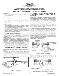
3Angle Moununtining (Figure 3) hangs from a vaulted or angled <strong>ceiling</strong>.preparing <strong>the</strong> fan siteFigurure 3 - Angle moununtiningThese guidelines are designed to help you select <strong>the</strong> best locationfor your fan and to prepare <strong>the</strong> site prior to <strong>installing</strong> <strong>the</strong> fan. Proper<strong>ceiling</strong> fan location and attachment to <strong>the</strong> building structure areessential for safety, reliable operation, maximum efficiency, and energysavings.choosing <strong>the</strong> fan site34º MaxPitch12Within <strong>the</strong> room where you want to install <strong>the</strong> fan, choose a fansite where:• No object can come in contact with <strong>the</strong> rotating fan bladesduring normal operation.• The fan blades are at least 7 feet above <strong>the</strong> floor and <strong>the</strong><strong>ceiling</strong> is at least 8 feet high.• The fan blades have no obstructions to air flow, such aswalls or posts, within 30 inches of <strong>the</strong> fan blade tips.• The fan is directly below a joist or support brace that willhold <strong>the</strong> outlet box and <strong>the</strong> full weight of <strong>the</strong> fan.See Figure 4 for <strong>the</strong> minimum mounting distances.8using an existing fan siteIf you are preparing a new fan site, go to <strong>the</strong> preparining a new fansite section.If you plan to use an existing fan site, complete <strong>the</strong> following checklistfor <strong>the</strong> support brace, <strong>ceiling</strong> hole, outlet box, and wiring. If youcannot check off every item, see <strong>the</strong> preparining a new fan site sectionfor instructions on properly preparing <strong>the</strong> site for your newfan.fan support system• <strong>Fan</strong> must attach directly to building structure.• <strong>Fan</strong> support system must hold full weight of fan and lightkit.<strong>ceiling</strong> hole• Outlet box clearance hole directly below <strong>the</strong> joist or supportbrace.outlet box• UL-approved octagonal 4" x 1-1/2" outlet box (or as specifiedby <strong>the</strong> support brace manufacturer).• Outlet box secured to joist or support brace by woodscrews and washers through inner holes of outlet box.• Outer holes of outlet box aligned with joist or supportbrace.• Bottom of outlet box recessed a minimum of 1/16" into<strong>ceiling</strong>.wiring• Electrical cable secured to outlet box by approved connector.• Six inches of lead wires extend from outlet box.See Figure 5 for an adequate existing fan site.Support BraceCeiling JoistApprovedConnector8’ MinimumCeiling Height7’ Minimumto FloorFigurure 4 - Mininimum imum moununtining distances30” FromWall orNearestObstructionWasherWood ScrewFigurure e 5 - Adequate e existining g fan siteIf your existing fan site is suitable, go to <strong>the</strong> installinlling <strong>the</strong> ceiliniling<strong>plate</strong> section and begin <strong>installing</strong> your new <strong>Hunter</strong> fan.preparing a new fan siteOutlet BoxCeilingTo prepare <strong>the</strong> fan site follow four steps:• Cutting <strong>the</strong> Ceiling Hole• Installing <strong>the</strong> Support Brace (if necessary)• Installing <strong>the</strong> Outlet Box• Preparing <strong>the</strong> Wiring© 2002 <strong>Hunter</strong> <strong>Fan</strong> Company 41800-01 11/02/2002
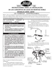
8Blade IronSwitch HousingMounting PlateUpper SwitchHousingHousingAssemblyScrewUpper PlugConnectorMedallionFigurure 24 - Attachining <strong>the</strong> blade to <strong>the</strong> blade iron andmedallillionIf you used grommets, <strong>the</strong> blades may appear slightly looseafter screws are tightened. This is normal.3. Remove <strong>the</strong> blade mounting screws and rubber shippingbumpers from <strong>the</strong> motor.4. For each blade, insert one blade mounting screw through <strong>the</strong>blade iron as shown in Figure 25, and attach lightly to <strong>the</strong> fan.Insert <strong>the</strong> second blade mounting screw, <strong>the</strong>n securely tightenboth mounting screws.Figurure 26 - Attachining <strong>the</strong> upper r switch housinsing to <strong>the</strong>moununtining <strong>plate</strong>3. Align <strong>the</strong> keyhole slots in <strong>the</strong> upper switch housing with <strong>the</strong>housing assembly screws installed previously.4. Turn <strong>the</strong> upper switch housing counterclockwise until <strong>the</strong>housing assembly screws are firmly situated in <strong>the</strong> narrow endof <strong>the</strong> keyhole slots as shown in Figure 27. Install <strong>the</strong> one remaining#6-32 x 3/8" housing assembly screw into <strong>the</strong> thirdhole in <strong>the</strong> upper switch housing. Tighten all three screws firmly.Figurure 25 - Attachining <strong>the</strong> blade iron to <strong>the</strong> fan<strong>installing</strong> <strong>the</strong> light fixtureYou can install with or without <strong>the</strong> light fixture. If you want toinstall without <strong>the</strong> light fixture, skip to <strong>the</strong> installinlling without t <strong>the</strong>light t fixturure section.attaching <strong>the</strong> upper switch housing1. Partially install two #6-32 x 3/8" housing assembly screws into<strong>the</strong> switch housing mounting <strong>plate</strong> as shown in Figure 26.2. Feed <strong>the</strong> upper plug connector through <strong>the</strong> center opening of<strong>the</strong> upper switch housing. See Figure 26.Figurure 27 - Moununtining <strong>the</strong> upper r switch housinsingCAUTION: N: Make e surure e <strong>the</strong> upper r switch housinsing g is s se-cururely y attached d to <strong>the</strong> switch housinsing g moununtining g <strong>plate</strong>. . Failil-ure e to properly y attach h and d tighten all ll thrhree e housinsing g assembmbly y screws s coululd d resulult t in <strong>the</strong> switch housinsing g and d lightfixturure e fallinlling.attaching <strong>the</strong> lower switch housing1. Connect <strong>the</strong> upper plug connector from <strong>the</strong> motor to <strong>the</strong> lowerplug connector in <strong>the</strong> lower switch housing assembly. See Figure28.NOTE: Both plug connectors are polarized and will only fit toge<strong>the</strong>rone way. Make sure that both connectors are properlyaligned before connecting <strong>the</strong>m toge<strong>the</strong>r. Incorrect connectioncould cause improper operation and damage to <strong>the</strong> product.Lower PlugConnectorUpper SwitchHousingUpper PlugConnectorHousingAssemblyScrewLowerSwitchHousingFigurure e 28 - Connnnectining g <strong>the</strong> plulug g connnnectors41800-01 11/02/2002 © 2002 <strong>Hunter</strong> <strong>Fan</strong> Company
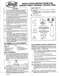
10<strong>installing</strong> <strong>the</strong> wiring harnessRefer to Figure 31.1. Insert <strong>the</strong> pull chain and fan pull chain switch through <strong>the</strong>round opening on <strong>the</strong> side of <strong>the</strong> switch housing. Thread <strong>the</strong>bellmouth nut over <strong>the</strong> pull chain and hand tighten <strong>the</strong>bellmouth nut.2. Reattach <strong>the</strong> patented breakaway connector to <strong>the</strong> end of <strong>the</strong>pull chain.3. Insert <strong>the</strong> reversing switch into <strong>the</strong> square hole on <strong>the</strong> side of<strong>the</strong> switch housing. Install and tighten <strong>the</strong> two screws youremoved previously from <strong>the</strong> o<strong>the</strong>r switch housing.4. Carefully place <strong>the</strong> capacitors in <strong>the</strong> switch housing.HousingAssemblyScrewCapacitorTwo-wire Light Plug Connector<strong>Fan</strong> SpeedSwitchoperating your <strong>ceiling</strong> fan1. Turn on electrical power to <strong>the</strong> fan.2. The fan pull chain controls power to <strong>the</strong> fan. The pull chainhas four settings in sequence: High, Medium, Low and Off.• Pull <strong>the</strong> chain slowly to change settings.• Release slowly to prevent <strong>the</strong> chain from recoiling into <strong>the</strong>blades.• The chain uses a breakaway connector that separates if<strong>the</strong> chain is jerked. If this happens, simply reinsert <strong>the</strong> chaininto <strong>the</strong> connector.3. The light pull chain controls power to <strong>the</strong> light. The pull chainhas two settings: On and Off.4. Ceiling fans work best by blowing air downward (counterclockwiseblade rotation) in warm wea<strong>the</strong>r to cool <strong>the</strong> room with adirect breeze. In winter, having <strong>the</strong> fan draw air upward (clockwiseblade rotation) will distribute <strong>the</strong> warmer air trapped at<strong>the</strong> <strong>ceiling</strong> around <strong>the</strong> room without causing a draft. Refer toFigure 32.ReverseSwitchMulti-wire Plug ConnectorCapacitorFigurure 31 - Reininstallinlling <strong>the</strong> wiririning harness<strong>installing</strong> <strong>the</strong> lower switch housing1. Connect <strong>the</strong> upper plug connector from <strong>the</strong> motor to <strong>the</strong> lowerplug connector in <strong>the</strong> lower switch housing assembly. See Figure28.NOTE: Both plug connectors are polarized and will only fit toge<strong>the</strong>rone way. Make sure that both connectors are properlyaligned before connecting <strong>the</strong>m toge<strong>the</strong>r. Incorrect connectioncould cause improper operation and damage to <strong>the</strong> product.2. Place <strong>the</strong> lower switch housing assembly over <strong>the</strong> upper switchhousing. Align <strong>the</strong> side screw holes in <strong>the</strong> upper and lowerswitch housings. Attach <strong>the</strong> lower switch housing to <strong>the</strong> upperswitch housing with three #6-32 x 3/8" housing assemblyscrews. See Figure 28.Figurure 32 - Air flow patternsTo change <strong>the</strong> direction of air flow, turn <strong>the</strong> fan off and let itcome to a complete stop. Slide <strong>the</strong> reversing switch on <strong>the</strong> fanto <strong>the</strong> opposite position as shown in Figure 33. Restart fan.<strong>Fan</strong> PullChainReversingSwitchFigurure e 33 - Pull ull chain and d reversinsing g switch41800-01 11/02/2002 © 2002 <strong>Hunter</strong> <strong>Fan</strong> Company
11cleaning your <strong>ceiling</strong> fancaring for finishesFor cleaning, a soft brush or lint-free cloth should be used to preventscratching <strong>the</strong> finish. A vacuum cleaner brush nozzle can removeheavier dust. Surface smudges or an accumulation of dirtand dust can easily be removed by using a mild detergent and aslightly dampened cloth. An artistic agent may be used, but neveruse abrasive cleaning agents as <strong>the</strong>y will damage <strong>the</strong> finish.caring for bladesWood finish blades should be cleaned with a furniture polishingcloth. Occasionally, a light coat of furniture polish may be appliedfor added protection and beauty. Painted and high-gloss bladesmay be cleaned in <strong>the</strong> same manner as <strong>the</strong> fan finish.troubleshootingProblem: Nothing happens; fan does not move.1. Turn power on, replace fuse, or reset breaker.2. Loosen canopy, check all connections according to <strong>the</strong>wiririning <strong>the</strong> fan section.3. Check <strong>the</strong> plug connection in <strong>the</strong> switch housing.4. Push motor reversing switch firmly up or down to ensurethat <strong>the</strong> switch is engaged.5. Pull <strong>the</strong> pull chain to ensure it is on.6. Remove <strong>the</strong> shipping bumpers.Problem: Noisy operation.1. Tighten <strong>the</strong> blade bracket screws until snug.2. Tighten <strong>the</strong> blade screws until snug.3. Check to see if <strong>the</strong> blade is cracked. If so, replace all <strong>the</strong>blades.4. Change to an approved speed control.5. Be sure that <strong>the</strong> Easy y Lock TM glass is fully engaged.6. Check and tighten <strong>the</strong> screws in <strong>the</strong> switch housingmounting <strong>plate</strong> and in <strong>the</strong> upper and lower switch housing.Problem: Excessive wobbling.1. If your fan wobbles when operating, use <strong>the</strong> enclosed balancingkit and instructions to balance <strong>the</strong> fan.2. Tighten all blade and/or blade iron screws.3. Turn power off, support fan very carefully, and check that<strong>the</strong> hanger ball is properly seated.If you need parts or service assistance, please call 888-830-1326 orvisit us at our WEB site at http://www.hunterfan.com.<strong>Hunter</strong> <strong>Fan</strong> Company2500 Frisco AvenueMemphis, Tennessee 38114© 2002 <strong>Hunter</strong> <strong>Fan</strong> Company 41800-01 11/02/2002