
Create successful ePaper yourself
Turn your PDF publications into a flip-book with our unique Google optimized e-Paper software.
Bisch<strong>of</strong> Dr. Markus DrögeEvangelische Kirche Berlin-Brandenburg-schlesische OberlausitzGrußwortZur Eröffnung des EKD Kirchen-Kultur-Kongresses15. September 2011Sehr geehrte Damen und Herren,der Systemtheoretiker und Soziologe Niklas Luhmann hatte zu allem etwas zu sagen.Natürlich auch zur „Kultur“. Dieser Begriff, so Luhmann, sei einer der schlimmsten,der je geprägt wurde. Denn ehe man sich´s versieht, wird unter der Hand alles,was man macht bzw. beobachtet, zur Kultur. Man kann also reden über was man will,man muss sich jedenfalls niemals die Sorge machen, es wäre nicht Kultur.Dieses Unbehagen hat Luhmann allerdings nicht davon abgehalten, selbst über Kulturzu schreiben und zu reden. Das finde ich sympathisch.Sympathisch finde ich auch, wie der Kirchen-Kultur-Kongress 2011 hier in Berlin diesesThema aufnimmt. In acht Themenfeldern an acht verschiedenen Orten werdenKirche und Kultur miteinander ins Gespräch gebracht und in Szene gesetzt. Die verschiedenenPerspektiven werden dann zentral präsentiert und gemeinsam diskutiert.Damit bleibt die Vielfalt an den dezentralen Orten bestehen. Man versucht nicht, allesam Ende zusammenzubinden oder auf einen Kulturbegriff zu bringen. Und trotzdemgibt es das Gespräch miteinander und Verbindungen werden geknüpft.All dies geschieht in der Perspektive der Freiheit. Kirche und Kultur sind Freiräume,so heißt es im Programm. Der Kirchenkulturkongress will Begegnungsort sein für„TheologInnen und Künstler, Ideenwerkstatt, Plattform für Unternehmungslustige,Club der Visionäre: für einen Glauben, der kreativ ist.“Schließlich wird nicht nur über Kultur geredet, sondern Theologen und Kulturschaffendeverantworten jeweils gemeinsam die acht Themenfelder.Kirche und Kultur, das finde ich an diesem Kongress besonders sympathisch, sollennicht miteinander verheiratet werden, sondern können in spannungsvoller FreiheitImpulse in die Gesellschaft und die Kirche einbringen. Es ist gut, dass dabei nichts<strong>of</strong>ort nach der Verwertbarkeit gefragt wird oder wie das denn umzusetzen ist, washier geschieht.Getrieben von der Leidenschaft für die Freiheit werden Kirche und Kultur sich alsonicht verheiraten, aneinander binden oder voneinander abhängig machen. Aber siekönnen dennoch Koalitionen eingehen, um die Freiheit gemeinsam zu verteidigen.1
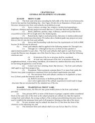
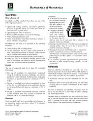
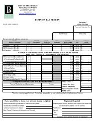
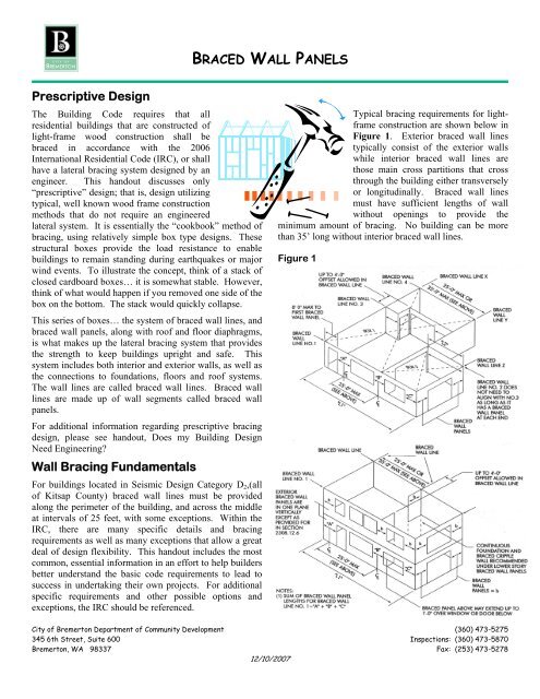
Some basic rules <strong>of</strong> prescriptive bracing in SeismicDesign Category D 2 are shown below. Many <strong>of</strong> the basicrules do, however, have exceptions that allow limitedmodification <strong>of</strong> the requirements. A double asterisk**below, signifies that exceptions exist, that will bediscussed in more detail later in this document.Braced Wall Lineso Every ro<strong>of</strong> and floor must be supported on allsides by braced wall lines.**o Braced wall lines must be placed across thebuilding at least every 25 feet.**o Braced wall lines may have <strong>of</strong>fsets <strong>of</strong> up to 4 feet(in each direction) along the length <strong>of</strong> the bracedwall line.o Braced wall lines must be perpendicular to eachother.o Buildings longer than 50 feet must havecontinuous footings and foundations under theinterior braced wall lines.**o If cripple walls are used (wood walls between thefoundation and the first floor framing) they mustbe constructed as braced wall lines andconsidered as an additional story if over 4 feettall.o Braced wall lines must have at least 25% <strong>of</strong> thewall area constructed as braced wall panels forsingle story buildings, or the top floor walls <strong>of</strong> atwo-story; and 55% <strong>of</strong> the wall area constructedas bracing on the first story walls <strong>of</strong> a two storybuilding.**Braced Wall Panelso Braced Wall panels must be at least 48 incheslong (plywood or OSB).**o Braced wall panels must be located at the ends <strong>of</strong>every braced wall line.**o Braced wall panels must be located at least every25 feet on center along every braced wall line.**o Braced wall panels may be constructed by anyone <strong>of</strong> seven allowable methods found in IRCSection R602.10.3, though the most commonmethods <strong>of</strong> braced wall panel construction aremethod #3, wood structural panel sheathing,(plywood or OSB) and method #5 for interiorwalls using gypsum wall board.o Required braced wall panels may be replaced by“Alternate Braced Wall Panels” that can be assmall as 2 feet 8 inches long.Braced Wall Panel LocationsBraced wall lines shall consist <strong>of</strong>braced wall panels that meet therequirements for location, type, andamount <strong>of</strong> bracing specified in the table below, and arein line or <strong>of</strong>fset from each other by not more than 4'.Braced wall panels shall be located at the end <strong>of</strong> eachbraced wall line, or may start up to 8 feet from the endprovided certain conditions are satisfied. All bracedwall panels shall be clearly indicated on the plans.Braced WallPanel LocationOne Story,or top story <strong>of</strong> atwo storyFirst Story <strong>of</strong> atwo storyCripple Wallsless than 48” tallIRC R602.10.3ConstructionMethod(s)2,3,4,5,6,7 or 82,3,4,5,6,7 or 8Method 3Bracing RequirementsLocated at each end and atleast every 25 feet on centerbut not less than 25% <strong>of</strong>braced wall line for Method 3and 40% <strong>of</strong> braced wall line forMethods 2,4,5,6,7 or 8.Located at each end and atleast every 25 feet on centerbut not less than 55% <strong>of</strong>braced wall line for Method 3and 75% <strong>of</strong> braced wall line forMethods 2,4,5,6,7 or 8Located at each end and atleast every 25 feet on centerbut not less than 75% <strong>of</strong>braced wall line.Braced Wall Panel ConstructionIRC Section R602.10.3 specifies 8 different methods toconstruct braced wall panels, however, in Seismic DesignCategory D 2 area, only Methods 2 through 8 areallowable. Method 3 is by far the most common method,and Method 5 is frequently used for interior braced wallpanels; they are described below. The other methods arenot described in this handout, however could be used.For the other methods, please see IRC Section R602.10.3.• Method 3: Wood structural panel sheathing witha thickness not less than 5/16" for 16" studspacing and not less than 3/8" for 24" studspacing. Wood structural panels shall be installedin accordance with IRC Table R602.3(3). SeeFigure 4)• Method 5: Gypsum sheathing, minimum ½ inchthickness, placed on studs spaced a maximum <strong>of</strong>24 inches on center and fastened with 1 ½ inchgalvanized ro<strong>of</strong>ing nails or 6d common nails at 7inches on center throughout; Or, gypsumwallboard (interior) fastened with 5d cooler nailsspaced 7” on center throughout.(See Figure 5)All vertical joints in braced wall panels shall occur overthe studs; all horizontal panel joints shall occur overblocking at least 1½ inches thick.#62—<strong>BRACED</strong> <strong>WALL</strong> <strong>PANELS</strong>Page 2
FIGURE 4:TYPICAL PRESCRIPTIVE <strong>BRACED</strong> <strong>WALL</strong> PANEL(per IRC Section R602.10.3, Method #3)4'-0" min.2 - 2x Top plates.Stagger joints 4'-0" min.Nail 16d at 16" oc.2x studs spaced 24" o.c. max. End nail studto top plate with 2-16d nails. Nail stud to sillplate with 4-8d toenails or 2-16d end nail.Wood structural panel sheathingminimum 5/16" thick for studs 16" oc.and minimum 3/8" thick for studs 24" oc.10'-0"Max.2x Blocking installed against sheathing andnailed to studs with 16d nails. Nail sheathingat 6 inches on center at panel edges and12 inches on center in the panel field.2x sill plate nailed to joist or blockingwith 3-16d nails per 16".Approved floor system*Nail sheathing with 8d common or galvanized box nails spaced 6" on centerat sheathing panel edges and 12" oc. in the field.#62—<strong>BRACED</strong> <strong>WALL</strong> <strong>PANELS</strong>Page 32x Pressure treated mud sill1/2" dia. anchor bolt with min. 7"embedment spaced 4'-0" on center fora two story building, 6'-0" on center fora single story building. One bolt within12" <strong>of</strong> each end <strong>of</strong> each piece <strong>of</strong> platematerial. 3"x3"x0.229" hot-dippedgalvanized plate washers are required.Approved Foundation System,Braced wall panels (BWP or ABP) must be located at each end <strong>of</strong> each braced wall line.Or, IRC Section R602.10.11 allows the braced wall panel (BWP) to be located up to 8' from the end <strong>of</strong>the braced wall line, provided there is a hold down device at the end <strong>of</strong> the BWP nearest the end <strong>of</strong> thebraced wall line. Additional options may also be available, See IRC 602.10 for more information.
FIGURE 5:PRESCRIPTIVE INTERIOR <strong>BRACED</strong> <strong>WALL</strong> PANEL(per IRC Section R602.10.3, Method #5)4'-0" min. for GWB on 2 sides8'-0" min. for GWB on one side2 - 2x Top plates.Stagger joints at least 4'-0" minimum.Nail 16d at 16" oc.2x studs spaced 24" o.c. max. End nail studto top plate with 2-16d nails. Nail stud to soleplate with 4-8d toenails or 2-16d end nail.1/2" thick min. gypsum wall board fastenedto all framing with screws or nails at 7" oncenter at all studs and blocking.Sheathing is shown cut away for clarity.10'-0"Max.2x Blocking installed against sheathing andnailed to studs with 16d nails. Nail sheathingat 7 inches on center at all panel edges andthroughout the panel field.2x sole plate nailed to joist or blockingwith 3-16d nails per 16"Approved floor system. Double joist underbraced wall panel where joists run parallelto BWP. Block between joists whererunning perpendicular to BWP.#62—<strong>BRACED</strong> <strong>WALL</strong> <strong>PANELS</strong>Page 4
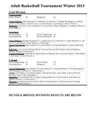
Alternate Braced Wall PanelsIn braced wall panel locations on exterior walls wherethe wall line is fully supported on a full foundation,standard 4 foot braced wall panels may be replaced byminimum 2’-8” alternate braced wall panel. This optionallows a shorter part <strong>of</strong> the wall to be used to provide theminimum bracing support. See Figure 6 on thefollowing page.Alternate Braced Wall Panels (ABWP) shall beconstructed as follows:In one-story buildings:(1,800# ABWP)• Each ABWP shall have a length <strong>of</strong> not less than 2feet, 8 inches and a height <strong>of</strong> not more than 10 feet.• Each ABWP shall be sheathed on one face with 3/8inch minimum thickness wood structural panelsheathing nailed with 8d common nails placed at 6inches on center around the panel perimeter, and 12inches on center in the panel field. All plywoodjoints shall be made over full blocking.• Each ABWP shall have at least two anchor boltsinstalled at the panel quarter points.• Each ABWP end stud shall have a tie-down devicefastened to the foundation, capable <strong>of</strong> providing anuplift capacity <strong>of</strong> not less than 1,800 lbs. The tiedowndevice shall be installed according to themanufacturer’s directions.• Each ABWP shall be supported directly on areinforced foundation, or on floor framing supporteddirectly on the foundation that is continuous acrossthe entire length <strong>of</strong> the braced wall line, such that thetie down device connects directly to the foundation.By city <strong>of</strong> <strong>Bremerton</strong> policy, it is allowable to use analternate braced wall panel on the top floor <strong>of</strong> a twostorybuilding provided a 3,000# ABWP is locateddirectly below the upper ABWP such that the tie-downdevices above connect directly to the foundation throughthe ABWP hold-down devices below. A complete loadpath to the foundation must be maintained.Lateral Restraint Panels (LRP)(Limited Allowable Uses)By city <strong>of</strong> <strong>Bremerton</strong> Policy, a lateral restraint panel(LRP) may replace any BWP required by code in asingle-story Group U occupancy only, such as asingle-story garage or storage shed. An LRP cannot beused in a house. See Figure 7 on page 7.An LRP shall have:• A width <strong>of</strong> at least 24".• A reinforced foundation, continuous across theentire braced wall line.• The solid header from the adjacent opening shallcontinue across the top <strong>of</strong> the LRP.• End studs shall be doubled and shall have tie-downdevices that provide an uplift capacity <strong>of</strong> not lessthan 2,400 lbs.• Two anchor bolts with 7" minimum embedment intothe reinforced concrete foundation.• Minimum 3/8" APA-rated sheathing nailed to allstuds, plates and headers with 8d nails placed 3" oncenter in all directions.In the first story <strong>of</strong> two-story buildings, (3,000# ABWP)each ABWP shall be constructed the same as for a onestorybuilding, except:• The wood structural panel sheathing shall beprovided on BOTH faces.• The sheathing edge-nailing spacing shall be at 4inches on center.• Three anchor bolts shall be placed at one-fifthpoints.• The tie-down devices shall provide an uplift capacity<strong>of</strong> not less than 3,000 lbs.For the purposes <strong>of</strong>calculating percentages<strong>of</strong> wall bracing along awall line, each ABWPor LRP may beconsidered to provide 4feet <strong>of</strong> required bracing.#62—<strong>BRACED</strong> <strong>WALL</strong> <strong>PANELS</strong>Page 5
FIGURE 6:PRESCRIPTIVE ALTERNATE <strong>BRACED</strong> <strong>WALL</strong> PANEL(per IRC Section R602.10.6).2'-8" minimum2 - 2x Top plates.Stagger joints 4'-0" min.Nail 16d at 16" oc.2x studs spaced 24" o.c. max. End nail studto top plate with 2-16d nails. Nail stud to sillplate with 4-8d toenails or 2-16d end nails.Wood structural panel sheathingminimum 5/16" thick for studs 16" oc.and minimum 3/8" thick for studs 24" oc.Sheath one side for single story, orboth sides if on the first <strong>of</strong> two stories.10'-0" Max2x Blocking installed against sheathing andnailed to studs with 16d nails. Nail sheathingto blocking and all panel edes at 6" on center.Approved steel hold down device.Install and fasten per manufacturer'sinstructions. 1800# capacity required forone story and the second <strong>of</strong> two stories,3000# capacity required for first <strong>of</strong> twostories.2x sill plate nailed to joist or blockingwith 3-16d nails in every 16 inches <strong>of</strong> plate.1/2" diameter anchor bolts with min. 7"embedment and 3"x 3"x 1/4" galvanizedsquare plate washers required. Two boltsrequired at quarter points for singlestory, three bolts required at fifth pointsfor two story construction.Approved floor systemApproved Foundation System*Nail sheathing with 8d common or galvanized box nails spaced 6" on centerat sheathing panel edges and 12" oc. in the field.#62—<strong>BRACED</strong> <strong>WALL</strong> <strong>PANELS</strong>Page 6
FIGURE 7:PRESCRIPTIVE LATERAL RESTRAINT PANEL2'-0" min.4x12 Header min.2 - 2x Top plates.Stagger joints 4'-0" min.Nail 16d at 16" oc.Nail sheathing to headerat 3" on center each way.Double 2x studs spaced 24" o.c. max.End nail stud to top plate with 2-16d nails.Nail each stud to sole plate with4-8d toenails or 2-16d end nails.10'-0" MaxMinimum 3/8" sheathing, ( APA rated 24/0,exposure 1- contact material supplier fordetails. Shown cut away for clarity).Nailed to all studs, headers and plateswith 8d nails at 3" on center.Approved hooked-end wood to concreteconnector (hold-down) installed on each end<strong>of</strong> panel. Fasten connectors per manufacturespecifications to develop min. 2400# capacity1/2" dia. anchor bolts with minimum 7"embedment, and 3"x3"x1/4" galvanizedsquare plate washers.Approved Foundation System*For use only in garage and shed end walls.If a floor intervenes between foundation and braced panel, the plywood shall overlapthe rim joist and sill plate. Provide holddowns, bolts and plywood nailing as shown.#62—<strong>BRACED</strong> <strong>WALL</strong> <strong>PANELS</strong>Page 7
Interior Braced WallPanel SupportIn one-story buildings located inSeismic Design Category D 2 , interiorbraced wall lines shall be supported oncontinuous foundations at intervals notexceeding 50 feet. In two storybuildings, all interior braced wall panelsshall be supported on continuousfoundations with the followingexception:Two-story buildings may haveinterior braced wall linessupported on continuousfoundations at intervals notexceeding 50 feet provided that:1. The height <strong>of</strong> cripple wallsdoes not exceed 4 feet and thecripple wall nailing pattern isincreased to 4 inches on center.2. Interior braced wall panelsare supported on doubled floorjoists, continuous blocking orfloor beams.3. The distance between bracinglines does not exceed twice thebuilding width measuredparallel to the braced wall line.Lateral Restraint Panels are for use only in single storyGroup U occupancies only,Or, portal frames in accordance with IRC Figure 602.10.6.2#62—<strong>BRACED</strong> <strong>WALL</strong> <strong>PANELS</strong>Page 8
Exceptions to the General Rules:Please keep in mind that when usingthese exceptions and options, suchinformation must be clearlyand accurately shown onthe construction plans!!!oooooRule: Every ro<strong>of</strong> and floor must besupported on all sides by braced wall lines.Exception: Covered porches and ro<strong>of</strong>extensions may extend up to 6 feet beyond abraced wall line provided there are no walls or floorssupported by such ro<strong>of</strong> extension.Excepton: Covered porches in accordance withmay extend up to a maximum <strong>of</strong> 16’ under certainconditions.Rule: Braced wall lines must be placed across thebuilding at least every 25 feet.Exception: One room can extend up to a maximum<strong>of</strong> 35 feet without an interior braced wall lineprovided the room is no more than 900 square feet inarea and bracing <strong>of</strong> the remaining walls at that levelmust have the minimum percentage <strong>of</strong> wall bracingadjusted by the values shown in Table R602.10.11below.TABLE R602.10.11ADJUSTMENT OF BRACING AMOUNTS FOR INTERIOR<strong>BRACED</strong> <strong>WALL</strong> LINES ACCORDING TO <strong>BRACED</strong> <strong>WALL</strong>SPACINGBraced Wall Line Spacing(feet)Multiply Bracing AmountsIn Table R602.10.1 By:ooo Rule: Braced wall panels must belocated at least every 25 feet on centeralong every braced wall line.o Exception: Don’t forget… Fortypical bracing (Method 3) thereneeds to also be 25% <strong>of</strong> wall area onsingle-story, or the top walls <strong>of</strong> twostorybuildings, and 55% <strong>of</strong> wall areaas bracing on the first floor <strong>of</strong> twostorybuildings (unless modified bythe Table R602.10.11 exception atleft). This provision usually meansfar more bracing than 25 feet oncenter will be required.Rule: Braced Wall panels must be at least 48 incheslong (plywood or OSB).Exceptions: The Alternate Braced Wall Panels andLateral Braced Wall Panels as described above maybe 2’8” and 2’0” respectively, though for percentagepurposes, may both be considered as 4 feet <strong>of</strong> wallbracing.There are also a few other conditional exceptions basedon policies utilizing specific products or specificmethods that have been approved for particular uses.Contact a Building Plans examiner for additional details.15 or less20253035.6.81.01.21.4The adjustment is limited to the larger spacing between bracedwall lines to either side <strong>of</strong> an interior braced wall lineNotice that when interior braced wall line spacing isgreater than 25 feet the amount <strong>of</strong> bracing is increased,however, when all interior braced wall line spacing isless than 25 feet on center, the amount <strong>of</strong> bracing isallowed to be reduced.#62—<strong>BRACED</strong> <strong>WALL</strong> <strong>PANELS</strong>Page 9
oRule: Braced wall panels must be located at the ends <strong>of</strong> every braced wall line as shown below.Minimum 48"8d nails at 6" o.c. at BWPpanel edges, 12" o.c.in panel field16d at 24" o.c.Minimum 48" wide woodstructural panel BWPlocated at end <strong>of</strong> walloR602.10.11, Braced Wall Panel at End <strong>of</strong> Braced Wall LineException: IRC Section R602.10.11 allows braced wall panels to be located up to 8 feet from the end <strong>of</strong> the bracedwall line provided that either one <strong>of</strong> the two following conditions are satisfied:1. A minimum 24-inch-wide panel is applied to each side <strong>of</strong> the building corner and the two 24-inch-wide panels atthe corner shall be attached to the framing in accordance with the figure below; Or,Maximum 8' 0"8d nails at 6" o.c. atpanel edges, 12" o.c.in panel fieldMin. 24" Minimum 48"BWPo16d at 24" o.c.Minimum 24" panelsat both sides <strong>of</strong> cornerMinimum 48" wide woodstructural panel BWPstarting within 8' <strong>of</strong> cornerR602.10.11, Exception Condition #12. The end <strong>of</strong> each braced wall panel closest to the corner shall have a tie-down device connecting the foundation tothe stud at the edge <strong>of</strong> the braced wall panel closest to the corner, as shown in the figure below. The tie-down deviceshall be capable <strong>of</strong> providing an uplift allowable design value <strong>of</strong> at least 1,800 pounds. The tie-down device shall beinstalled in accordance with the manufacturer’s directions.Maximum 8' 0"Minimum 48"BWPMinimum 1800# capacityhold-down device locatedat the end <strong>of</strong> BWPnearest the end <strong>of</strong> thebraced wall lineR602.10.11, Exception Condition #2Minimum 48" wide BWPstarting within 8" <strong>of</strong> corner8d nails at 6" o.c. atpanel edges, 12" o.c.in panel field#62—<strong>BRACED</strong> <strong>WALL</strong> <strong>PANELS</strong>Page 10