Silver Direct Silent Back EMF DCC Decoder - Lenz USA
Silver Direct Silent Back EMF DCC Decoder - Lenz USA
Silver Direct Silent Back EMF DCC Decoder - Lenz USA

You also want an ePaper? Increase the reach of your titles
YUMPU automatically turns print PDFs into web optimized ePapers that Google loves.
<strong>Silver</strong> <strong>Direct</strong> Locomotive decoder 3Special FeaturesFunction for disabling of acceleration and deceleration delayUse function F4 (function assignment can be altered in CV59) to disablethe acceleration and braking delay as well as the constant brakingdistance during operation. The delays are disabled as long as the functionis active.Switching speed functionThe switching speed halves the speed table. This facilitates particularlysensitive control during the switching process. Use function 3 (functionsetting, can be altered in CV58) to enable and disable the switchingspeed. If the shunting speed is enabled, the constant braking distance isdisabled. The switching speed is enabled as long as the function is activeConstant braking distanceDuring the transition from an active speed step to speed step 0 (e.g.moving the speed control knob to the left limit-stop), the locomotive/trainwill travel a settable, pre-defined braking distance. This braking distancedoes not depend on the speed of the locomotive/train.Enable the constant braking distance function (this requires setting Bit0(1) in CV51. If this bit is not set, the decoder will use the normal speeddependentbraking delay).The braking distance is defined by the value set in CV52. Since themotors and gear ratios of locomotives vary, the braking distance differsfrom locomotive to locomotive even if the same value is set in CV52.Use a short test section to measure how long your locomotive’s brakingdistance will be with a given value set in CV52. Start with the default value(100) in CV52.Accelerate your locomotive until it has reached average speed.At a chosen point in time, set the speed to 0. This requires moving thespeed control to the stop position, if you are using the LH100, keeppressing the < key until the speed is set to 0 or until the locomotiveaddress is displayed (if using the LH100, do not press key ! This resultin a locomotive-specific emergency stop and the delays in the locomotivedecoder will not be enabled!).Measure the covered braking distance.Increase or decrease the value in CV52, e.g. in steps of 10, and carry outanother measurement. You will thus create a table which will indicate thebraking distances in relation to the values set in CV52.Important advice: The constant braking distance is only effective if thespeed is changed to 0. If the speed is decreased from e.g. 28 to 10, thespeed-dependent delay from CV4 becomes effective.The constant braking distance is disabled while the switching speedfunction is switched on (default setting F3), or if the function to disableacceleration/deceleration is activated (default setting F4). Either of these
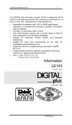
<strong>Silver</strong> <strong>Direct</strong> Locomotive decoder 5Some advice on installing the decoder:Although the SILVER decoder has many internal safeguards to preventdamage, you must not allow any metal part of the locomotive to touch thesurface components of the decoder. This could cause a direct internalshort circuit and the decoder will be destroyed. The motor brushesMUST also be completely isolated from the rail pickup. Achievingisolation may require some different approaches on different locomotives,perhaps unsoldering wires or placing a thin piece of insulating plasticbetween the motor and the locomotive frame. If you have a VOM, checkfor infinite resistance between the motor and all the wheels. Take specialnote that a short might occur when the loco body is reinstalled.DO NOT WRAP decoder with electrical tape or shrink wrap!Doing so will impede air circulation and degrade the performance of thedecoder. Instead, put electrician tape over any part of the locomotiveframe or body that might touch the decoder and use double sided foammounting tape to mount the decoder. This will prevent short circuitswithout 'suffocating' the decoder.The SILVER decoder can not be set up for simultaneous use for 2-railpickup and overhead cantenary or trolley operation. If the locomotive isturned the wrong way, the decoder could get twice the track voltage,which would destroy it!Wiring OptionsThe <strong>Silver</strong> <strong>Direct</strong> is designed for locomotives that have an NMRA 8 pinsocket. To install simply remove the dummy plug from the locomotive andplug in the decoder.Step by Step InstallationTo install the decoder simply remove the dummy plug in your locomotiveand install the decoder plug. To ensure the headlights work correctly youmust align the plug properly. Pin 1 of the plug connects to the orangewire. Ensure this is aligned to Pin 1 of the locomotive. If the plug isinstalled wrong way round the lights will not work. When installing the plugensure that the pins are not bent or broken.1Function output DFunction positive common +View from bottom of decoderPinMeaning1 Motor connection 12 Function output B(rear headlight)
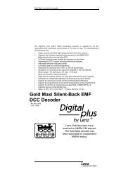
<strong>Silver</strong> <strong>Direct</strong> Locomotive decoder 63 Function output C4 Left rail pickup5 Motor connection 26 Function output A(front headlight)7 Function positive common8 Right rail pickupThere are two wiring options for installing the function D to the solder padson the underside of the decoder depending on how the locomotive isconstructed. The function could be connected to the decoder’s floatingpositive +common ( Pin 7) or connected to one rail as a common. Amixture of both options is possible in the same locomotive.1Function D withrail CommonF1Function D with <strong>Decoder</strong> + CommonFIf the bulbs are floating (isolated against wheel pick up and chassis) andconnected according to above figure, they will shine brighter compared tousing the rail as a common.After installation of the decoder, place the locomotive (without its shell) onthe programming track and read back the locomotive's address from thedecoder. If the decoder is properly installed, you will be able to read backthe factory pre-set address 03. Remove the locomotive from the track,and if necessary correct any wiring errors.Configuring the <strong>Silver</strong> <strong>Decoder</strong>The locomotive address, acceleration and deceleration delay, and allother features of the locomotive decoder can be changed as often asdesired by configuring special features within the decoder. The featuresare "stored" permanently in special locations even when the operationalvoltage is switched off. These locations are called "configurationvariables" or simply "CV". The values are configured electronically, whichmeans that it is not necessary to open the locomotive again after thedecoder has been installed.You can alter the content of CVs both through "Programming inoperational mode (PoM)" (except for CV1, CV17 and CV18) or"Programming on the programming track".6
<strong>Silver</strong> <strong>Direct</strong> Locomotive decoder 7For detailed instructions on how to program using the above-mentioneddevices, please refer to the operating manuals which accompany thosedevices.The decoder is programmed from the factory for operation with address 3and 28 speed steps. The decoder can be used with these basicconfigurations immediately after purchase. All configurations can, ofcourse, be changed.Resetting the decoderIf you wish to reset all the decoder CVs to its factory setting, enter value33 in CV8. The CVs of a connected S.U.S.I. module are not reset!Please note: Some CVs (such as CV29) have specific meanings for eachbit. The bit assignments in this table use a bit numbering scheme of 0-7 tocorrespond the NMRA convention for universal bit numbering. Manyhandhelds (such as the DIGITAL plus LH100 handheld) use a scheme of1-8 to refer to the individual bits rather than 0-7. (Bit 0 in this table isdisplayed as a"1" on LH100 handheld, Bit 1 is identified as "2".) The bitnumbers in () within these tables contain the LH100 bit numbers.**Note: in the range field the numbers in the [ ] are decimal.
<strong>Silver</strong> <strong>Direct</strong> Locomotive decoder 8Table of supported CVsCV Meaning1 Basic locomotive address. This number is the short addressused to control the locomotive. When writing this CV, CV19(consist address) is automatically cleared and CV29 Bit 6(use of extended address) is deleted is set to 0.RangeFactorysetting1-127 32 Minimum starting voltage 0-255 03 Starting delay 0-255 64 Braking delay 0-255 55 Maximum speed 0-255 2556 Mid speed Vmid (a value of 60 will give a linear curve) 0-255 487 Version number - 788 Manufacturer’s ID - 999 <strong>Back</strong> <strong>EMF</strong> Repetition Rate 0-63 1517 Extended locomotive address, high-order byte 192-231 19218 Extended locomotive address, low-order byte 0-255 10019 Consist address 1-99 029 <strong>Decoder</strong> Configuration, Byte 1: 6 (dec)bit 0(1)bit 1(2)bit 2(3)bit 3(4)bit 4(5)bit 5(6)Locomotive direction of travel:0 = locomotive’s direction is normal1 = locomotive’s direction is reversedHeadlight mode:0 = Operation with 14 or 27 speed step systems..1 = Operation with 28, 55 or 128 speed steps.Note: your system must be set to the same mode.Usage on conventional DC layouts:0 = locomotive operates in digital mode only1 = locomotive can operate on either conventional DCand on <strong>DCC</strong>Not Used 0 0Speed Curve Selection:0 = factory pre-set speed curve is used1 = user defined speed curve is used. Please enter theappropriate values into CV 67 to 94 before setting thisbit.Extended Addressing0= Normal addressing1= Four digit extended addressing0,1[1]0,1[2]0,1[4]0,1[16]0-1[32]bit 6 bit 7 always 0 0 0011008
<strong>Silver</strong> <strong>Direct</strong> Locomotive decoder 11Left Blank for notes:
<strong>Silver</strong> <strong>Direct</strong> Locomotive decoder 12North American Warranty<strong>Lenz</strong> GmbH does everything it can do to ensure that its products are free fromdefects and will operate for the life of your model railroad equipment. From time totime even the best engineered products fail either due to a faulty part or fromaccidental mistakes in installation. To protect your investment in Digital plusproducts, <strong>Lenz</strong> GmbH offers a very aggressive 10 year Limited Warranty.This warranty is not valid if the user has altered, intentionally misused the DigitalPlus product, or removed the product's protection, for example the heat shrink fromdecoders and other devices. In this case a service charge will be applied for allrepairs or replacements. Should the user desire to alter a Digital Plus Product, theyshould contact <strong>Lenz</strong> GmbH for prior authorization.Year One: A full repair or replacement will be provided to the original purchaser forany item that that has failed due to manufacturer defects or failures caused byaccidental user installation problems. Should the item no longer be produced andthe item is not repairable, a similar item will be substituted at the manufacturer’sdiscretion. The user must pay for shipping to an authorized <strong>Lenz</strong> GmbH warrantycenter.Year 2 and 3: A full replacement for any item will be provided that has failed dueto manufacturer defects. If the failure was caused by accidental user installation oruse, a minimal service charge may be imposed. Should the item no longer beproduced and the item is not repairable, a similar item will be substituted at themanufacturer’s discretion. The user must pay shipping to and from the authorized<strong>Lenz</strong> GmbH warranty center during this portion of the warranty period.Year 4-10: A minimal service charge will be placed on each item that has faileddue to manufacturer defects and/or accidental user installation problems. Shouldthe item no longer be produced and the item is not repairable, a similar item will besubstituted at the manufacturer’s discretion. The user must pay shipping to andfrom the authorized <strong>Lenz</strong> GmbH warranty center during this portion of the warrantyperiod.Please contact your dealer or authorized <strong>Lenz</strong> GmbH warranty center for specificinstructions and current service charges prior to returning any equipment for repair.Hüttenbergstraße 2935398 Gießen, GermanyHotline: 06403 900 133Fax: 06403 900155info@digital-plus.dehttp://www.lenz.com<strong>Lenz</strong> Agency of North AmericaPO Box 143Chelmsford, MA 01824ph: 978 250 1494fax: 978 455 LENZsupport@lenz.comThis equipment complies with Part 15 of FCC Rules. Operation is subject to thefollowing two conditions: (1) this device may not cause harmful interference, and(2) this device must accept any interference received, including interference thatmay cause undesired operation.Please save this manual for future reference!© 2007 <strong>Lenz</strong> GmbH, All Rights Reserved12