Marconi IFR Aeroflex 2025 Datasheet - Testwall
Marconi IFR Aeroflex 2025 Datasheet - Testwall
Marconi IFR Aeroflex 2025 Datasheet - Testwall

Create successful ePaper yourself
Turn your PDF publications into a flip-book with our unique Google optimized e-Paper software.
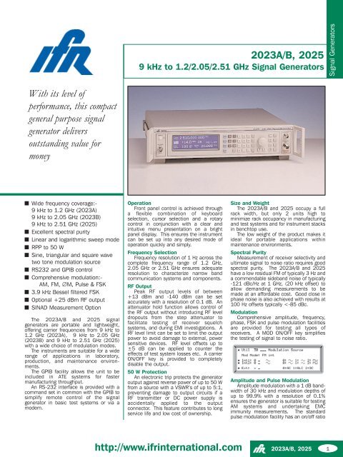
2023A/B, <strong>2025</strong>9 kHz to 1.2/2.05/2.51 GHz Signal GeneratorsSignal GeneratorsWith its level ofperformance, this compactgeneral purpose signalgenerator deliversoutstanding value formoneyWide frequency coverage:-9 kHz to 1.2 GHz (2023A)9 kHz to 2.05 GHz (2023B)9 kHz to 2.51 GHz (<strong>2025</strong>)Excellent spectral purityLinear and logarithmic sweep modeRPP to 50 WSine, triangular and square wavetwo tone modulation sourceRS232 and GPIB controlComprehensive modulation:-AM, FM, ∅M, Pulse & FSK3.9 kHz Bessel filtered FSKOptional +25 dBm RF outputSINAD Measurement OptionThe 2023A/B and <strong>2025</strong> signalgenerators are portable and lightweight,offering carrier frequencies from 9 kHz to1.2 GHz (2023A), 9 kHz to 2.05 GHz(2023B) and 9 kHz to 2.51 GHz (<strong>2025</strong>)with a wide choice of modulation modes.The instruments are suitable for a widerange of applications in laboratory,production, and maintenance environments.The GPIB facility allows the unit to beincluded in ATE systems for fastermanufacturing throughput.An RS-232 interface is provided with acommand set in common with the GPIB tosimplify remote control of the signalgenerator in basic test systems or via amodem.OperationFront panel control is achieved througha flexible combination of keyboardselection, cursor selection and a rotarycontrol in conjunction with a clear andintuitive menu presentation on a brightpanel display. This ensures the instrumentcan be set up into any desired mode ofoperation quickly and simply.Frequency SelectionFrequency resolution of 1 Hz across thecomplete frequency range of 1.2 GHz,2.05 GHz or 2.51 GHz ensures adequateresolution to characterize narrow bandcommunication systems and components.RF OutputPeak RF output levels of between+13 dBm and -140 dBm can be setaccurately with a resolution of 0.1 dB. Anattenuator hold function allows control ofthe RF output without introducing RF leveldropouts from the step attenuator tofacilitate testing of receiver squelchsystems, and during EMI investigations. ARF level limit can be set to limit the outputpower to avoid damage to external, powersensitive devices. RF level offsets up to±5 dB can be applied to counter theeffects of test system losses etc. A carrierON/OFF key is provided to completelydisable the output.50 W ProtectionAn electronic trip protects the generatoroutput against reverse power of up to 50 Wfrom a source with a VSWR’s of up to 5:1,preventing damage to output circuits if aRF transmitter or DC power supply isaccidentally applied to the outputconnector. This feature contributes to longservice life and low cost of ownership.Size and WeightThe 2023A/B and <strong>2025</strong> occupy a fullrack width, but only 2 units high tominimize rack occupancy in manufacturingand test systems and for instrument stacksin benchtop use.The low weight of the product makes itideal for portable applications withinmaintenance environments.Spectral PurityMeasurement of receiver selectivity andultimate signal to noise ratio requires goodspectral purity. The 2023A/B and <strong>2025</strong>have a low residual FM of typically 3 Hz anda commendable sideband noise of typically-121 dBc/Hz at 1 GHz, (20 kHz offset) toallow demanding measurements to bemade at an affordable cost. Good close inphase noise is also achieved with results at100 Hz offsets typically
2023A/B, <strong>2025</strong>of better than 40 dB and a rise/fall time ofless than 10 µs enabling characterizationof TDMA or TDD bursts in RF amplifiers andmodules. The internal square wavemodulation source may be used to selfpulse modulate the generator for use inEMI applications.An optional Fast Pulse modulatorimproves the on/off ratio to typically>80 dB with rise and fall times of
use in production racks.SpecificationGeneral DescriptionThe 2023A/B and <strong>2025</strong> cover the frequency range9 kHz to 1.2 GHz, 2.05 GHz and 2.51 GHzrespectively.The RF output can be amplitude, frequency, phaseor pulse modulated. An internal synthesizedprogrammable AF source is capable of generatingsingle or simultaneous two tone modulation.GPIB and RS-232 are included as standard toenable remote control of all functions except thesupply switch.Carrier FrequencyRange9 kHz to 1.2 GHz (2023A)9 kHz to 2.05 GHz (2023B)9 kHz to 2.51 GHz (<strong>2025</strong>)Resolution1HzAccuracyAs frequency standard.Phase incrementingThe carrier phase can be advanced or retarded insteps as low as 0.09° using the rotary control.RF OutputRange-140 dBm to +13 dBm, 0.1 dB resolution. WhenAM is selected, the maximum RF output leveldecreases linearly with increasing AM depth to+7 dBm at 99.9% depth.RF Level UnitsUnits may be set to µV, mV, EMF or PD; dB relativeto 1 µV 1 mV EMF or PD; or dBm. Conversionbetween dB and linear units may be achieved bypressing the appropriate units key (dB or V, mV, µV.)The output level can be normalized for 75 Ωoperation with an impedance converter.Level Accuracy(1)FrequencyTemp>-127 dBm >-100 dBm Coefficient9 kHz to1.2 GHz ±0.8 ±0.8 ±0.02 dB/°C1.2 GHz to2.05 GHz ±1.4 ±1.2 ±0.03 dB/°C2.05 GHz to2.51 GHz ±1.6 ±1.6 ±0.03 dB/°C(1)Over range +17°C to +27°CAttenuator HoldSelection of Attenuator hold provides foruncalibrated level reduction of at least 10 dBwithout the Mechanical Attenuator operating.VSWRFor output levels less than -5 dBm, output VSWR isless than 1.3:1 for carrier frequencies up to 1.2 GHzand less than 1.5:1 for carrier frequencies up to2.51 GHz.For output levels greater than -5 dBm output VSWRis less than 1.5:1 for all carrier frequencies.RF Output Connector50 Ω type N connector to MIL 390123D.Output ProtectionProtected from a source of reverse power up to50 W from 50 Ω or 25 W from a source VSWR of5:1. Protection circuit can be reset from the frontpanel or via the GPIB/RS-232 interfaces.Spectral PurityAt RF levels up to +7 dBm:HarmonicsTypically better than -30 dBc for RF levels up to+7 dBm.Typically better than -25 dBc for RF levels up to+13 dBm.Non-Harmonics (for offsets >3 kHz)Better than -70 dBc to 1 GHz, better than -64 dBcbetween 1 and 2.05 GHz better than -60 dBc above2.05 GHz.Residual FM (FM off)Less than 4.5 Hz RMS deviation in a 300 Hz to3.4 kHz unweighted bandwidth at 1 GHz.SSB Phase NoiseBetter than -124 dBc/Hz at 20 kHz offset from acarrier frequency of 470 MHz, typically -121 dBc/Hzat 20 kHz offset from a carrier frequency of 1 GHz.Carrier leakageLess than 0.5 µV PD at the carrier frequency in atwo turn 25 mm diameter loop, 25 mm from thesurface of the signal generator.ΦM on AMTypically 0.1 radians at 30% depth at 470 MHz.Modulation ModesInternal and external modulation can besimultaneously enabled to allow combined amplitudeand frequency (or phase) modulation.Pulse modulation can be used in combination withthe other forms of modulation from an externalpulse source.Frequency ModulationResolution1 HzDeviationCW Range (MHz)Max Deviation (kHz)1200 - 2510 12800600 - 1200 6400300 - 600 3200150 - 300 160075 - 150 80037.5 - 75 40018.75 - 37.5 2000.009 - 18.75 100Accuracy at 1 kHz±4%Bandwidth (1 dB)DC to 275 kHz (DC coupled)10 Hz to 275 kHz (AC coupled)20 Hz to 275 kHz (AC coupled with ALC).Group delayLess than 5 µs to 100 kHz.Carrier frequency offset (DC coupled)Less than 1% of the set frequency deviation.Distortion