
You also want an ePaper? Increase the reach of your titles
YUMPU automatically turns print PDFs into web optimized ePapers that Google loves.
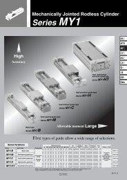
Non-rotating <strong>Double</strong> <strong>Power</strong> <strong>Cylinder</strong>/(without non-rotating<strong>Double</strong> <strong>Power</strong> <strong>Cylinder</strong> mechanism)Series <strong>MGZ</strong>/<strong>MGZ</strong>Rø20, ø25, ø32, ø40, ø50, ø63, ø80, ø1001MXMTSMYCYMGCXD--X20-DataNow also available in ø20 and ø25.8-25-1
<strong>Double</strong> extensionoutput powerOur unique construction doubles theextended piston area. An ideal cylinder forlifting and press applications.Air pressure supplied from A operates on both surfaces q and w.(Extension) q w A BAir pressure supplied from B operates on surfaces e.(Retraction)eA BSay goodbye to nonrotatingguides!!(Series <strong>MGZ</strong>)Slide key x 2Tube rod diameterExternal dimensionNon-rotating <strong>Double</strong> <strong>Power</strong> <strong>Cylinder</strong>Series <strong>MGZ</strong> employs a slidebearing and a large boretube rod that accounts forapproximately 80% of thecylinder's external diameter.In addition, a built-in nonrotatingmechanism usingslide keys allows loads tobe mounted directly.Regulator with check valveis not required.A regulator with check valve, normally required for a liftingcircuit, is no longer necessary.Series <strong>MGZ</strong>ø20, ø25, ø32, ø40, ø50, ø63, ø80Improved workpiecemounting accuracyPositioning holes on the workpiecemounting surface allow easy alignment.ø20areExcellent strength deliveredin a small package.Although moment resistance is equivalent to that of a guided cylinder (cylinder + 2 guideshafts), the installation area has been reduced by approximately 40% (for Series <strong>MGZ</strong>).<strong>Double</strong> <strong>Power</strong> <strong>Cylinder</strong>Series <strong>MGZ</strong>Rø20, ø25, ø32, ø40, ø50, ø63, ø80and ø25 sizesnewly added.Note)Strokes up to 1,000 mm areavailable. Unlike conventionaltandem type double outputcylinders, whose length is morethan twice the stroke length, ourdouble output cylinders aremarkedly more compact.Note) Strokes up to 800 mm areavailable in bore sizes ø20 andø25.Series VariationsNameModelNon-rotating double<strong>MGZ</strong>power cylinder<strong>MGZ</strong>R<strong>Double</strong> power cylinder(without non-rotating mechanism)Note) Except ø20, ø25, ø32 and ø80.Long stroke availableSpace-savingBore size(mm)20, 25, 32, 4050, 63, 80Flush, unencumbered appearanceAuto switches can be housed in grooves on 4 sides.Piping is concentrated in the head cover.With endlock(Approx. 30%reduction)Note)With coilscraperApplication ExamplePushingTransaxialfoot styleChuckingMounting bracketFrontflange styleRearflange style —(without non-rotatingmechanism)PressingLiftingShooting<strong>Double</strong>clevis —2MXMTSMYCYMGCXD--X20-DataWith front end lock on rod saideFor drop protection(<strong>MGZ</strong> only)<strong>Double</strong> clevis typeFor rotating applications.(<strong>MGZ</strong>R only)With coil scraper8-25-28-25-3
3Series <strong>MGZ</strong>Series <strong>MGZ</strong>/<strong>MGZ</strong>RModel Selection1. Confirmation of Allowable Load Weight by Each ApplicationCautionTheoretical output must beconfirmed separately.Refer to the theoretical out puttable on page 8-25-9.Selection conditions: Determine which of the conditions below matches your intended application, then choose one of the selection graphs that follow.Vertical upward: LiftermlVertical downward: PressHorizontal: ChuckinglmFmFMaximum speed (mm/s)Maximum speed (mm/s)up to 300Graph (1)up to 500Graph (2)up to 700Graph (3)up to 300Graph (4)up to 500Graph (5)∗ l: This dimension indicates the position of the load center of gravity when the cylinder is retracted.Load center of gravity position l (mm)up to 100 up to 200Graph (6) Graph (7)up to 300Graph (8)Selection Graph (1) to (3) (Vertical upward mounting)Graph (1) up to 300 mm/sSolid line: Operating pressure 0.4 MPa or moreDotted line: Operating pressure 0.5 MPa or moreGraph (2) up to 500 mm/sSolid line: Operating pressure 0.4 MPa or moreDotted line: Operating pressure 0.5 MPa or more400300Load weight m (kg)100ø80ø63ø5010ø40ø32ø25ø20210 100 300Eccentricity distance l (mm)Load weight m (kg)100ø80ø6310ø50ø40ø25 ø32[Example q] ø201 10 100 300Eccentricity distance l (mm)Graph (3) up to 700 mm/s200Solid line: Operating pressure 0.4 MPa or moreSelection Example:Vertical Upward MountingLoad weight m (kg)10010ø80ø63ø50ø401ø32ø20 ø250.510 100 300Eccentricity distance l (mm)q Selection conditions Mounting: Vertical upward (Lifter)Maximum speed: 500 mm/sLoad weight: 40 kgEccentricity distance: 80 mmSince the conditions are vertical upward mounting with a speedof 500 mm/s, use graph (2). In the graph, find where the linesrepresenting a load weight of 40 kg and an eccentric distance of80 mm intersect. From the graph, a ø63 bore size is selected.8-25-4
Model Selection Series <strong>MGZ</strong>/<strong>MGZ</strong>R4Selection Graph (4) and (5) (Vertical downward mounting)Graph (4) up to 300 mm/sLoad weight m (kg)200150100ø80ø63ø5050ø40ø32ø25ø2000.3 0.4 0.5 0.6 0.7 0.8 0.9 1Operating pressure P (MPa)00.3 0.4 0.5 0.6 0.7 0.8 0.9 1Operating pressure P (MPa)Selection Graph (6) to (8) (Horizontal mounting)Load weight m (kg)12010080604020Graph (6) l: 100 mm or less Graph (7) l: 101 to 200 mm Graph (8) l: 201 to 300 mm300100Graph (5) up to 500 mm/s200100ø80ø63ø50ø40ø32Selection Example:Horizontal Mountingw Selection conditionsMounting: Horizontal (Chucking)Stroke: 300 mmLoad center of gravity position: 100 mmLoad weight: 10 kgOperating pressure: 0.5 MPaRefer to graph (6) based on the horizontalmounting and the load center of gravityposition. In the graph, find where the linesrepres-enting a load weight of 10 kg and astroke of 300 mm intersect. A ø50 boresize is selected.The theoretical output for the extensionstroke is 1924 N, from the theoretical outputtable on page 8-25-9.100MXMTSMYCYMGCXD--X20-DataLoad weight m (kg)ø8010ø63ø501ø40[Example w]ø32ø20 ø250.170 100 1000Stroke (mm)Load weight m (kg)ø8010ø63ø501ø20ø25ø400.3ø3270 100 1000Stroke (mm)Load weight m (kg)ø8010ø63ø501ø20 ø25 ø400.3ø3270 100 1000Stroke (mm)2. Confirmation of allowable rotating torque 3. Confirmation of non-rotating accuracyT3-1 Rolling direction 3-2 Pitching direction+θ θ +θ θ +θ θ Allowable Rotating Torque Non-rotating Accuracy Deflection Angle of Eccentric LoadBore size (mm) Allowable rotating torque T (N⋅m) Bore size (mm) Non-rotating accuracy (θ) Bore size (mm) Non-rotating accuracy (θ)202.720200.4 or less2542525324057324032400.12 or less5063801520305063800.3 or less5063808-25-5
Model Selection Series <strong>MGZ</strong>/<strong>MGZ</strong>R6Selection Graph (4), (5), and (6)(Load extended horizontally)Graph (4) up to 300 mm/sLoad weight m (kg)Load weight m (kg)1000800600400ø80ø63ø50ø40200ø32ø25ø2000.1 0.2 0.3 0.4 0.5 0.6 0.7 0.8 0.9 1700600500400Operating pressure P (MPa)Graph (5) up to 500 mm/sø80ø63300200ø50ø40100ø32ø25ø2000.1 0.2 0.3 0.4 0.5 0.6 0.7 0.8 0.9 1Operating pressure P (MPa)Selection Graph (7) and (8)(Load retracted horizontally)Graph (7) up to 300 mm/sLoad weight m (kg)Load weight m (kg)300250200150100ø80ø63ø50ø4050ø32ø25ø2000.1 0.2 0.3 0.4 0.5 0.6 0.7 0.8 0.9 116014012010080604020Operating pressure P (MPa)Graph (8) up to 450 mm/s00.1 0.2 0.3 0.4 0.5 0.6 0.7 0.8 0.9 1Operating pressure P (MPa)ø80ø63ø50ø40ø322. Confirmation of allowable kinetic energyConfirm the strength of the built-in stopper (rubberbumper) based on the correlation of load weight andthe maximum speed. If the value isBelow the line in the graph: A built-in stopper can be used.Above the line in the graph: Either use a cylinder with a largerbore size or install an external stopperLoad weight m (kg)100010010ø20ø80ø63ø50ø40ø32ø25150 1001000Operating pressure P (MPa)MXMTSMYCYMGCXD--X20-DataGraph (6) up to 700 mm/s400ø80Selection Example:Load Extended HorizontallyLoad weight m (kg)350300250200150ø63ø5010050ø40ø32ø25ø2000.1 0.2 0.3 0.4 0.5 0.6 0.7 0.8 0.9 1Operating pressure P (MPa)w Selection conditionsMounting: Horizontal extrusionMaximum speed: 500 mm/sOperating pressure: 0.6 MPaLoad weight: 200 kgSince the conditions are horizontalextension with a speed of 500 mm/s, usegraph (5). In the graph, find where thelines representing an operating pressureof 0.6 MPa and a load weight of 200 kgintersect. A ø63 bore size is selected.8-25-7
7Non-rotating <strong>Double</strong> <strong>Power</strong> <strong>Cylinder</strong>Series <strong>MGZ</strong>ø20, ø25, ø32, ø40, ø50, ø63, ø80How to Order<strong>MGZ</strong>40 Z 100 Z73NilLFGMounting styleBasic styleTransaxial foot styleFront flange styleRear flange style2025324020 mm25 mm32 mm40 mmNilTNTFBore size50638050 mm63 mm80 mmThread typeM5 x 0.8RcNPTGø20ø25ø32ø40ø50ø63ø80Number of auto switchesAuto switchWithout auto switchNil(Built-in magnet)∗ For the applicable auto switch model,refer to the table below.∗ Auto switches are shipped together,(but not assembled).Stroke (mm)Refer to “Standard Stroke” on page 8-25-9.Coil scraperNilS2 pcs.1 pc.NilZNoneYesApplicable Auto Switch: ø20, ø25, ø32TypeReedswitchSolid state switchApplicable Auto Switch: ø40, ø50, ø63, ø80TypeReedswitchSolid state switchSpecial function——Diagnostic indication(2-color indication)Improved water resistance(2-color indication)Special function——Diagnostic indication(2-color indication)ElectricalentryGrommetGrommetElectricalentryGrommetGrommetWiring(Output)Improved water resistance2-wire(2-color indication)∗ Lead wire length symbols: 0.5 m ············Nil (Example) Y69B3 m ············ L (Example) Y69BL5 m ············ Z (Example) Y69BZ8-25-8IndicatorlightNoYesYesIndicatorlightWiring(Output)2-wire3-wire(NPN equiv.)3-wire (NPN)3-wire (PNP)2-wire3-wire (NPN)3-wire (PNP)2-wireLoad voltageLoad voltageDCACYes3-wire(NPN equiv.) 5 V 12 V 100 V2-wire 24 VNo5 V, 12 V 100 V or less3-wire (NPN)3-wire (PNP)2-wire5 V, 12 V12 VYes 3-wire (NPN) 24 V 5 V, 12 V3-wire (PNP)12 VAuto switch modelElectrical entry directionDC ACPerpendicular In-line24 V5 V, 12 V 100 V or less A90V A9012 V 100 V A93V A93 5 V A96V A965 V, 12 VM9NV M9NM9PV M9P12 VM9BV M9B24 V F9NWV F9NW5 V, 12 VF9PWV F9PW12 VF9BWV F9BW— F9BAAuto switch modelElectrical entry directionPerpendicular In-line— Z76— Z73—Y69AY7PVY69BY7NWVY7PWVY7BWV—Z80Y59AY7PY59BY7NWY7PWY7BWY7BALead wire length (m) ∗0.5(Nil)Lead wire length (m) ∗0.5(Nil)3(L)5(Z)ApplicableloadRelayPLCRelayPLCNote) Solid state switches marked “” are produced upon receipt of order. Retrofitting of an auto switch on a cylinder that is originally ordered without onerequires a switch spacer per the next page.3(L)5(Z) IC circuit IC circuitIC circuit IC circuitApplicableloadIC circuitIC circuitIC circuitIC circuitRelayPLCRelayPLC
Series <strong>MGZ</strong>9Constructiony @0 q o @2 i r t !7 @4 @1 e u !9 !8 @5 @3 w !6 !5 !1!2 !0@6!3 !4!7 @3ø20, ø25With coil scraperComponent PartsNo.qwertyuio!0!1!2!3DescriptionRod coverHead cover<strong>Cylinder</strong> tubePiston rodTube rodTube rod coverPistonStationary pistonBushingThrust plateHolderPinTie-rodMaterialAluminum alloyAluminum alloyAluminum alloyAluminum alloyCarbon steel tubeCarbon steelAluminum alloyAluminum alloyLead-bronze castingLead-bronze castingAluminum alloyCarbon steelCarbon steelNoteClear anodizedClear anodizedHard anodizedHard anodizedHard chromium electronplatedElectroless nickel platedChromatedChromatedChromatedZinc chromatedCorrosion resistant chromatedNo.!4!5!6!7!8!9@0∗@1@2@3@4@5∗@6DescriptionTie-rod nutHexagon socket head screwSpring washerBumperWear ringMagnetRod seal ARod seal BPiston sealPiston gasketTube rod gasket<strong>Cylinder</strong> tube gasketCoil scraperMaterialCarbon steelChrome molybdenum steelSteel wireUrethane rubberResinMagnetNBRNBRNBRNBRNBRNBRMetalNoteNickel platedNickel platedNickel platedReplacement Parts: Seal KitBore size (mm)Kit no.Contents2025<strong>MGZ</strong>20-PS<strong>MGZ</strong>25-PS32<strong>MGZ</strong>32-PSItems @0 and @5 from40<strong>MGZ</strong>40-PSthe above chart506380<strong>MGZ</strong>50-PS<strong>MGZ</strong>63-PS<strong>MGZ</strong>80-PS∗ Seal kits consist of items @0 and @5, and can be ordered by using the sealkit number corresponding to each bore size.8-25-10
Non-rotating <strong>Double</strong> <strong>Power</strong> <strong>Cylinder</strong> Series <strong>MGZ</strong>10DimensionsBasic style2–P(Rc, NPT, G)GAGBYYMXMTSMY4–MM depth M øXA H7 depth 6 +0.20CYø IMGCXøDD--XEKACBKHMCNAS + StrokeNBMA2 x 4–JMB20-DataZZ + StrokeThe allowable angle difference of E to B should be limited to ±1.5.(mm)Bore size(mm)20253240506380StrokerangeUp to 800Up to 800Up to 1000Up to 1000Up to 1000Up to 1000Up to 1000B394349597182106C29333846556686D25303645556887E11121621263236KA21243036465365GA162628.534.54046.554GB12.51819.523.52834.536H20213540455050I5157667892110144JM5 x 0.8M5 x 0.8M6 x 1M6 x 1M8 x 1.25M8 x 1.25M12 x 1.75K11122225252525M881010141420Bore size(mm)20253240506380StrokerangeUp to 800Up to 800Up to 1000Up to 1000Up to 1000Up to 1000Up to 1000MA11111616161620MB4444556MC10101212151523MMM5 x 0.8M5 x 0.8M6 x 1M6 x 1M8 x 1.25M8 x 1.25M12 x 1.75NA19263744505666NB2134PM5 x 0.81/81/81/41/41/43/8S86107120138150171198XA661212161620Y56.58.59.512.51520ZZ1061281551781952212488-25-11
Series <strong>MGZ</strong>11With Mounting BracketTransaxial foot style: (L)LY4-øLD through(mm)Bore size(mm)20253240506380StrokerangeUp to 800Up to 800Up to 1000Up to 1000Up to 1000Up to 1000Up to 1000X16162224323640Y0000133LD6.66.699111317LH222427.534404759LT13141619222430LX5862708096110146LY41.545.55263.575.588112LZ727588100120140180LS86107120138148165192ZZ114136166190210236265Front flange style: (F)Bore size(mm)20253240506380StrokerangeUp to 800Up to 800Up to 1000Up to 1000Up to 1000Up to 1000Up to 1000B4448607478100120FD5.56.69991214FT881212161616FX50576480100112132FY34364658617595(mm)FZ607078100125138155Rear flange style: (G)4-øFDFYBLTLHLXLZYXLS + StrokeZZ + StrokeX/2X4-øFDFYBFXFZFTFXFZZZ + StrokeFT(mm)Bore size(mm)20253240506380StrokerangeUp to 800Up to 800Up to 1000Up to 1000Up to 1000Up to 1000Up to 1000B4448607478100120FD5.56.69991214FT881212161616FX50576480100112132FY34364658617595FZ607078100125138155ZZ1141361671902112372648-25-12
12MXMTSMYCYMGCXD--X20-Data8-25-13
Non-rotating <strong>Double</strong> <strong>Power</strong> <strong>Cylinder</strong>With End Lock on Rod SideSeries <strong>MGZ</strong>ø40, ø50, ø6313How to Order<strong>MGZ</strong>40 100 RZ73NilLFGMounting styleBasic styleTransaxial foot styleFront flange styleRear flange style405063Bore size40 mm50 mm63 mmThread typeNilTNTFRcNPTGNumber of auto switchesNilS2 pcs.1 pc.Auto switchWithout auto switchNil(Built-in magnet)∗ For the applicable auto switch model,refer to the table below.∗ Auto switches are shipped together,(but not assembled).With end lock on rod sideStroke (mm)Refer to “Standard Stroke” on page 8-25-15.Applicable Auto Switch: Direct Mounting TypeTypeReedswitchSolid state switchSpecial function——Diagnostic indication(2-color indication)Improved water resistance(2-color indication)ElectricalentryGrommetGrommetLoad voltage Auto switch modelWiringElectrical entry direction(Output) DCACPerpendicular In-line3-wire(NPN equip.) 5 V Z76Yes12 V 100 V Z732-wire 24 VNo5 V, 12 V 100 V or less Z803-wire (NPN)Y69A Y59A5 V, 12 V3-wire (PNP)Y7PV Y7P2-wire12 VY69B Y59BYes 3-wire (NPN) 24 V Y7NWV Y7NW5 V, 12 V3-wire (PNP)Y7PWV Y7PWY7BWV Y7BW2-wire12 V Y7BAIndicatorlight∗ Lead wire length symbols:0.5 m ···············Nil(Example) Y69B3 m ··············· L (Example) Y69BL5 m ··············· Z (Example) Y69BZNotes) Solid state switches marked “” are produced upon receipt of order. Retrofitting of an auto switch on a cylinder that is originally orderedwithout one requires a switch spacer per the table below.Switch spacerLead wire length (m) ∗0.5(Nil)3(L)5(Z)ApplicableloadIC circuitIC circuitIC circuitIC circuitRelayPLCRelayPLCSwitch SpacerApplicable bore size (mm)Switch spacer modelMounting Bracket Part No.Bore size (mm) 40Foot <strong>MGZ</strong>-L04Flange <strong>MGZ</strong>-F0440, 50, 63BMP1-03250 63<strong>MGZ</strong>-L05 <strong>MGZ</strong>-L06<strong>MGZ</strong>-F05 <strong>MGZ</strong>-F068-25-14
Non-rotating <strong>Double</strong> <strong>Power</strong> <strong>Cylinder</strong>With End Lock on Rod SideSeries <strong>MGZ</strong>14<strong>Cylinder</strong> SpecificationsBore size (mm)40 50 63ActionFluidProof pressureMax. operating pressureMin. operating pressureAmbient and fluid temperatureLubricationPiston speed<strong>Double</strong> acting, Single rodAir1.5 MPa1.0 MPa0.2 MPa∗Without auto switch: 10 to 70 C (With no freezing)With auto switch: 10 to 60 C (With no freezing)Non-lubeOUT 50 to 700 mm/sIN 50 to 450 mm/s+1.0+1.4Stroke length toleranceUp to 250 0 , 251 to 1000 0CushionScrew toleranceMountingRubber bumperJIS class 2Basic style, Transaxial foot style, Front flange style, Rear flange style∗ 0.08 MPa (or 0.12 MPa for long strokes) except the lock part.Lock SpecificationsEnd lock positionHolding force (max)NBacklashManual releaseø401770Rod side onlyø5026902 mm or lessNon-locking typeø634160Adjust the switch position so that it operates upon movement to both the stroke end and backlash (2 mm)position.MXMTSMYCYMGCXD--X20-DataStandard StrokeBore sizes (mm)40, 50, 63Standard strokes (mm)75, 100, 125, 150, 175200, 250, 300Long strokes (mm)350, 400, 450, 500, 600700, 800, 900,1000Intermediate strokes and strokes shorter than 75 mm are also available.WeightStandard weightBore size (mm)Weight per each 50 mmof strokeBasic styleFoot styleFlange styleAll mountingbrackets402.803.293.240.41504.084.974.840.61636.137.397.130.80(kg)Theoretical OutputModel<strong>MGZ</strong>40<strong>MGZ</strong>50<strong>MGZ</strong>63Bore size(mm)45 x 404055 x 505068 x 6363Rod size(mm)202532OperatingdirectionOUTINOUTINOUTINPiston area(mm 2 )253394238481473594523130.250718877029511894630.3760283115444217846940.4101337715395892378925Operating pressure (MPa)0.512674711924737297311570.615205652309884356713880.7177365926941031416216190.8202675430781178475618500.922808483463132653512082(N)1.0253394238481473594523138-25-15
Series <strong>MGZ</strong>15Constructiony@9 qo#1irt @4 !7 #3 #0 @3 ue @6 !9 !8 $0 #4 #9 @5 #2 w !6 !5 !1 !2 !0#7 @1 #5 @2 @8 @7 #6 @0 #8!3 !4End lockComponent PartsNo.qwertyuio!0!1!2!3!4!5!6!7!8!9@0DescriptionRod coverHead cover<strong>Cylinder</strong> tubePiston rodTube rodTube rod coverPistonStationary pistonBushingThrust plateHolderPinTie-rodTie-rod nutHexagon socket head screwSpring washerBumperWear ringMagnetCapMaterialAluminum alloyAluminum alloyAluminum alloyAluminum alloyCarbon steel tubeCarbon steelAluminum alloyAluminum alloyLead-bronze castedLead-bronze castedAluminum alloyCarbon steelCarbon steelCarbon steelChrome molybdenum steelSteel wireUrethane rubberResinMagnetBronze alloyNoteClear anodizedClear anodizedHard anodizedHard anodizedHard chromium electroplatedElectroless nickel platedChromatedChromatedChromatedZinc chromatedCorrosion resistant chromatedNickel platedNickel platedNickel platedElectroless nickel platedNo.@1@2@3@4@5@6@7@8@9∗#0#1#2#3#4∗#5∗#6∗#7∗#8∗#9∗$0∗DescriptionLock holderLock pistonStopperCollarPort blockPipeLock springRubber capRod seal ARod seal BPiston sealPiston gasketTube rod gasket<strong>Cylinder</strong> tube gasketLocking piston seal ALocking piston seal BLocking piston seal CLock holder gasketPort block gasketPipe gasketMaterialNoteStainless steelCarbon steel Quenched, hard chromium electroplatedCarbon steel QuenchedLead-bronze castedBronze alloy Electroless nickel platedBronze alloySteel wireSynthetic rubberNBRNBRNBRNBRNBRNBRNBRNBRNBRNBRNBRNBRReplacement Parts: Seal KitBore size (mm)405063Kit no.<strong>MGZ</strong>40R-PS<strong>MGZ</strong>50R-PS<strong>MGZ</strong>63R-PSContentsItems @9, and #4 to $0from the above chart∗ Seal kits consist of items @9 and #4 to $0, and can be ordered by using theseal kit number corresponding to each bore size.8-25-16
Non-rotating <strong>Double</strong> <strong>Power</strong> <strong>Cylinder</strong>With End Lock on Rod SideSeries <strong>MGZ</strong>16DimensionsBasic styleDL2-P(Rc, NPT, G)GAGBY YWMMXMTS4-MM depth MøXA H7 depth XL+0.20WLLLLMMYCYHRøIMGCXøDD--XEKACKMCNBNMA2 x 4-JMB20-DataBHS + StrokeZZ + Stroke(mm)Bore size(mm)405063StrokerangeUp to 1000Up to 1000Up to 1000B597182C465566D455568DL586773E212632GA34.54046.5GB23.52834.5H404550HR57.563.569I7892110JM6 x 1.0M8 x 1.25M8 x 1.25K252525KA364653LL303030LM303030Bore size(mm)405063StrokerangeUp to 1000Up to 1000Up to 1000M101414MA161616MB455MC121515MMM6 x 1.0M8 x 1.25M8 x 1.25N445056NB748389P1/41/41/4S168183204XA121616XL666Y9.512.515WL WM ZZ4242523942522082282548-25-17
Series <strong>MGZ</strong>17With Mounting BracketTransaxial foot style: (L)4-øLD throughLTLHLYX/2LXLZYXLS + StrokeZZ + StrokeX(mm)Bore size(mm)StrokerangeXYLDLHLTLXLYLZLSZZ405063Up to 1000Up to 1000Up to 100024323601391113344047192224809611063.575.588100120140168181198220243269Front flange style: (F)4-øFDFYBFXFZFT(mm)Bore size(mm)StrokerangeBFDFTFXFYFZ405063Up to 1000Up to 1000Up to 10007478100991212161680100112586175100125138Rear flange style: (G)4-øFDFYBFXFZZZ + StrokeFT(mm)Bore size(mm)StrokerangeBFDFTFXFYFZZZ405063Up to 1000Up to 1000Up to 100074781009912121616801001125861751001251382202442708-25-18
18MXMTSMYCYMGCXD--X20-Data8-25-19
<strong>Double</strong> <strong>Power</strong> <strong>Cylinder</strong>(Without non-rotating mechanism)Series <strong>MGZ</strong>Rø20, ø25, ø32, ø40, ø50, ø63, ø8019How to Order<strong>MGZ</strong> R40Z100Z73Without non-rotating mechanismNilLFGDMounting styleBasic styleTransaxial foot styleFront flange styleRear flange style<strong>Double</strong> clevis style2025324020 mm25 mm32 mm40 mmNilTNTF506380Bore size50 mm63 mm80 mmThread typeM5 x 0.8RcNPTGø20ø25ø32ø40ø50ø63ø80Coil scraperNilZNumber of auto switchesNilS2 pcs.1 pc.Auto switchWithout auto switchNil(Built-in magnet)∗ For the applicable auto switch model,refer to the table below.∗ Auto switches are shipped together,(but not assembled).Stroke (mm)Refer to “Standard Stroke” on page 8-25-21.Without coil scraperWith coil scraperApplicable Auto Switch: ø20, ø25, ø32TypeReedswitchSolid state switchSpecial function——Diagnostic indication(2-color indication)Improved water resistance(2-color indication)Applicable Auto Switch: ø40, ø50, ø63, ø80TypeReedswitchSolid state switchSpecial function——Diagnostic indication(2-color indication)Improved water resistance(2-color indication)Load voltage Auto switch modelElectrical WiringElectrical entry directionentry (Output) DC ACPerpendicular In-lineNo5 V, 12 V 100 V or less A90V A902-wire 24 VGrommet12 V 100 V A93V A93Yes 3-wire(NPN equiv) 5 V A96V A963-wire (NPN)M9NV M9N5 V, 12 V3-wire (PNP)M9PV M9P2-wire12 VM9BV M9BGrommet Yes 3-wire (NPN) 24 V F9NWV F9NW5 V, 12 V3-wire (PNP)F9PWV F9PWF9BWV F9BW2-wire12 V F9BAElectricalentryGrommetGrommetIndicatorlightLoad voltage Auto switch modelWiringElectrical entry direction(Output) DC ACPerpendicular In-line3-wire(NPN equiv.) 5 V Z76Yes12 V 100 V Z732-wire 24 VNo5 V, 12 V 100 V or less Z803-wire (NPN)Y69A Y59A5 V, 12 V3-wire (PNP)Y7PV Y7P2-wire12 VY69B Y59BYes 3-wire (NPN) 24 V Y7NWV Y7NW5 V, 12 V3-wire (PNP)Y7PWV Y7PWY7BWV Y7BW2-wire12 V Y7BAIndicatorlight∗ Lead wire length symbols: 0.5 m···············Nil (Example) Y69B3 m ··············· L (Example) Y69BL5 m ··············· Z (Example) Y69BZ8-25-20Lead wire length (m) ∗0.5(Nil)Lead wire length (m) ∗0.5(Nil)3(L)3(L)5(Z)5(Z)IC circuitIC circuitIC circuitIC circuitApplicableloadRelayPLCRelayPLCApplicableloadIC circuitIC circuitIC circuitIC circuitRelayPLCRelayPLCNotes) Solid state switches marked “” are produced upon receipt of order. Retrofitting of an auto switch on a cylinder that is originally ordered without onerequires a switch spacer per the next page.
<strong>Double</strong> <strong>Power</strong> <strong>Cylinder</strong>(Without non-rotating mechanism)Series <strong>MGZ</strong>R20Switch Spacer ModelApplicable bore size (mm)Switch spacer modelFoot <strong>MGZ</strong>-L05 <strong>MGZ</strong>-L06 <strong>MGZ</strong>-L08Flange <strong>MGZ</strong>-F05 <strong>MGZ</strong>-F06 <strong>MGZ</strong>-F08Note)<strong>Double</strong>clevis<strong>MGZ</strong>-D05 <strong>MGZ</strong>-D06 <strong>MGZ</strong>-D08Note) <strong>Double</strong> clevis bracket is providedwith clevis pins and cotter pins.Switch spacer20, 25, 32BMY3-016Mounting Bracket Part No.Bore size(mm)FootFlangeNote)<strong>Double</strong>clevisBore size(mm)2025<strong>MGZ</strong>-D2540, 50, 63, 80BMP1-03232<strong>MGZ</strong>-D0340<strong>MGZ</strong>-L02 <strong>MGZ</strong>-L25 <strong>MGZ</strong>-L03 <strong>MGZ</strong>-L04<strong>MGZ</strong>-F02 <strong>MGZ</strong>-F25 <strong>MGZ</strong>-F03 <strong>MGZ</strong>-F04<strong>MGZ</strong>-D02506380<strong>MGZ</strong>-D04SpecificationsBore size (mm)ActionFluidProof pressureMax. operating pressureMin. operating pressureAmbient and fluid temperatureLubricationOUTPiston speedINStroke length toleranceCushionScrew toleranceMountingStandard StrokeBore sizes (mm)Weight20, 2532, 40, 5063, 80Bore size (mm)Basic styleFoot styleStandard weightFlange style<strong>Double</strong> clevis styleWeight per each50 mm of strokeAll mountingbrackets20 25 32 40 50 63 80<strong>Double</strong> acting, Single rodAir1.5 MPa1.0 MPaStandard stroke: 0.08 MPaLong stroke: 0.12 MPaWithout auto switch: 10 to 70 C (With no freezing)With auto switch: 10 to 60 C (With no freezing)Non-lube50 to 700 mm/s50 to 350 mm/s 50 to 450 mm/s+1.0+1.4Up to 250 0 , 251 to 1000 0Rubber bumperJIS class 2Basic style, Transaxial foot style, Front flange styleRear flange style, <strong>Double</strong> clevis styleStandard strokes (mm)75, 100, 125, 150, 175200, 250, 30075, 100, 125, 150, 175200, 250, 300Intermediate strokes and strokes shorter than 75mm are also available.Theoretical OutputModel<strong>MGZ</strong>20<strong>MGZ</strong>25<strong>MGZ</strong>32<strong>MGZ</strong>40<strong>MGZ</strong>50<strong>MGZ</strong>63<strong>MGZ</strong>80Bore size(mm)20 x 252025 x 302536 x 323245 x 404055 x 505068 x 636387 x 8080Rod size(mm)10121620253240OUTINOUTINOUTINOUTINOUTINOUTINOUTIN200.480.630.590.580.19Operating Piston areadirection (mm 2 )7262361085378162160325339423848147359452313971537700.2145472177632412150718877029511894631943754250.700.860.830.830.220.3218713261134861817602831154442178469429151131321.091.341.321.320.290.429094434151648241101337715395892378925388615080.5363118543189811302126747119247372973115748581885401.912.392.342.190.39Long strokes (mm)350, 400, 450, 500600, 700, 800350, 400, 450, 500, 600700, 800, 900,10000.6436141651227973362152056523098843567138858292262503.033.923.793.470.59Operating pressure (MPa)0.750816576026511354221773659269410314162161968012639634.836.085.835.620.780.8581189868302129748220267543078117847561850777230160.965321297734014595432280848346313265351208287443393(kg)808.8510.619.9210.661.21(N)1.0726236108537816216032533942384814735945231397153770MXMTSMYCYMGCXD--X20-Data8-25-21
Series <strong>MGZ</strong>R21Constructiony !6 q o !8 i r t !4 @0 !7 e u @2 !5 @1 !9 w !3 !2!0 !1@3 !4!9ø20, ø25Component PartsNo.qDescriptionRod coverMaterialAluminum alloyNoteClear anodizedNo.!3DescriptionSpring washerMaterialSteel wireNoteNickel platedwHead coverAluminum alloyClear anodized!4BumperUrethane rubbere<strong>Cylinder</strong> tubeAluminum alloyHard anodized!5Wear ringResinrtPiston rodTube rodAluminum alloyCarbon steelHard anodizedHard chromium electroplated!6!7∗Rod seal ARod seal BNBRNBRyTube rod coverCarbon steelElectroless nickel plated!8Piston sealNBRuPistonAluminum alloyChromated!9Piston gasketNBRiStationary pistonAluminum alloyChromated@0Tube rod gasketNBRo!0!1BushingTie-rodTie-rod nutLead bronze castedCarbon steelCarbon steelCorrosion resistant chromatedNickel plated@1@2∗@3<strong>Cylinder</strong> tube gasketMagnetCoil scraperNBRMagnetMetal!2Hexagon socket head screwChrome molybdenum steelNickel platedReplacement Parts: Seal KitBore size (mm)20253240506380Kit no.<strong>MGZ</strong>20-PS<strong>MGZ</strong>25-PS<strong>MGZ</strong>32-PS<strong>MGZ</strong>40-PS<strong>MGZ</strong>50-PS<strong>MGZ</strong>63-PS<strong>MGZ</strong>80-PSContentsItems !6 and @1 fromthe above chart∗ Seal kits consist of items !6 and @1, and can be ordered by using the sealkit number corresponding to each bore size.8-25-22
<strong>Double</strong> <strong>Power</strong> <strong>Cylinder</strong>(Without non-rotating mechanism)Series <strong>MGZ</strong>R22DimensionsBasic style2-P(Rc,NPT,G)GAGBYYMXMTSMYMM depth MCYøIMGCXøDD--XKACBKHMCNAS + StrokeZZ + StrokeMANB2 x 4-JMB20-Data(mm)Bore size(mm)StrokerangeBCDKAGAGBHIJKMMAMBMCMMNANBPSYZZ20253240506380Up to 800Up to 800Up to 1000Up to 1000Up to 1000Up to 1000Up to 1000394349597182106293338465566862530364555688721243036465365162628.534.54046.55412.51819.523.52834.536202135404550505157667892110144M5 x 0.8M5 x 0.8M6 x 1M6 x 1M8 x 1.25M8 x 1.25M12 x 1.75111222252525251717223035353811111616161620444455610101212151523M8 x 1.25M8 x 1.25M10 x 1.5M16 x 2M20 x 2.5M20 x 2.5M22 x 2.519 2126 343744505666M5 x 0.81/81/81/41/41/43/88610712013815017119856.58.59.512.515201061281551781952212488-25-23
Series <strong>MGZ</strong>R23Dimensions: With Mounting BracketTransaxial foot style: (L)LY4-øLD throughLXLZLTLHYXLS + StrokeZZ + StrokeXX2(mm)Bore size(mm)20253240506380StrokerangeUp to 800Up to 800Up to 1000Up to 1000Up to 1000Up to 1000Up to 1000X16162224323640Y0000133LD6.66.699111317LH222427.534404759LT13141619222430LX586296110146110146LY41.545.55263.575.588112LZ727588100120140180LS86107120138148165192ZZ114136166190210236265Front flange style: (F)Rear flange style: (G)FYBFYBFXFZ4-øFDFTFXFZ4-øFDZZ + StrokeFT(mm)(mm)Bore size(mm)20253240506380StrokerangeUp to 800Up to 800Up to 1000Up to 1000Up to 1000Up to 1000Up to 1000B4448607478100120FD5.56.69991214FT881212161616FX50576480100112132FY34364658617595FZ607078100125138155Bore size(mm)20253240506380StrokerangeUp to 800Up to 800Up to 1000Up to 1000Up to 1000Up to 1000Up to 1000B4448607478100120FD5.56.69991214FT881212161616FX50576480100112132FY34364658617595FZ607078100125138155ZZ114136167190211237264<strong>Double</strong> clevis style: (D)∗Clevis pins and cotter pinsare included.Z + StrokeZZ + StrokeULRRøCDH10CXCZ(mm)Bore size(mm)20253240506380StrokerangeUp to 250Up to 350Up to 600Up to 600Up to 700Up to 900Up to 900L23233030424250RR8.5111215182328U14141717262630CDH1010101414222225CX+0.3+0.114142020303032CZ28284040606064Z129151185208237263298ZZ137.51621972232552863268-25-24
<strong>Double</strong> <strong>Power</strong> <strong>Cylinder</strong>(Without non-rotating mechanism)Series <strong>MGZ</strong>R24<strong>Double</strong> Clevis BracketZ + StrokeDBøDDBDX4-øDTBDHMXDUDLDADU4-øDRDODCDEDODSMTSMYModelMB-B03MB-B05MB-B08MB-B12Bore size(mm)20253240506380B394349597182106DA42425353737390DB32324343646478444460608686110A°DC90°DDH1010101414222225+0.0580+0.0580+0.0700+0.0700+0.0840+0.0840+0.0840B°DE62628181111111136DH33334545656575DL22223030454560DO9910.510.512.512.513DR6.66.699111113.5RotationDS7788101014Bore size(mm)202532, 4050, 63DT15151818222224A°35303035DU101011.511.5141415B°50505050DX14142020303032A° + B° + 90°175170170175Z129151185208237263298CYMGCXD--X20-DataClevis PinmlL2-ødøDd9ModelBore sized(mm)Dd9 L l m(Drill through)–0.040CD-M03 20, 25 10 –0.076–0.050CD-M05 32, 40 14 –0.093–0.065CD-M08 50, 63 22 –0.117–0.065CDP-7A 80 25 –0.117446082883651727844.5553444Note) When using cotter pins, flat washers are used together.Note)Cotter pinø3 x 18 lø4 x 25 lø4 x 35 lø4 x 36 lFloating JointCenter of sphereMMUøDUApplicablebore size20, 25324050, 6380ModelJB40-8-125JB63-10-150JB80-16-200JB100-20-250JB140-22-250MNominalsize810162022Pitch1.251.522.52.5FA5162.580.5101129B8.510162118C1113202622D31415059.579BCE67.59.511.514ERF1114192430AG1113.5162022GPH2227324146Center ofsphereR2935.547.55971.5Max.screw-indepth P1315182438HAllowableeccentricityU0.7511.2522.5Max. operating tensionand compression NCompression Tension600011000180002800054000130031005000790015300(mm)Weight(kg)0.150.290.561.042.68-25-25
Series <strong>MGZ</strong>/<strong>MGZ</strong>R25Proper Auto Switch Mounting Position (Detection at stroke end)0 to 1 A BBore size(mm)202532D-A9, A9VA242422B334D-M9N/M9P/M9BD-F9NW/F9PW/F9BWAB287287268D-F9BALA272725B667Bore size(mm)40506380D-Z7/Z80D-Y59/Y69/Y7P/Y7PVD-Y7W/Y7WVD-Y7BALA23233237B0004Operating RangeMinimum Stroke for MountingAuto switch modelD-A9, A9VD-M9N/M9P/M9BD-F9NW/F9PW/F9BWD-F9BALAuto switch modelD-Z7/Z80D-Y59/Y69/Y7P/Y7PVD-Y7W/Y7WVD-Y7BALBore size (mm)20 25 328 9.5 83 3 3.55 5 4.55 6 5∗ The operating range for the <strong>MGZ</strong>P series isunder examination.Bore size (mm)40 50 63 8010 10 11 1365.555.5∗ Hysteresis specifications are given as a guide,it is not a guaranteed range. (Tolerance 30%)Hysteresis may fluctuate due to the operatingenvironment.6687Auto switchtypeReed switchSolid stateswitchAuto switchtypeReed switchSolid stateswitchModelD-A9/A9VD-M9N/M9P/M9BD-F9NW/F9PW/F9BWD-F9BALModelD-Z7/Z80D-Y59/Y69/Y7P/Y7PVD-Y7W/Y7WVD-Y7BALNo. of auto switches2 pcs. (same side)1 or 2 pcs. (different sides)2 pcs. (same side)1 or 2 pcs. (different sides)2 pcs. (same side)1 or 2 pcs. (different sides)2 pcs. (same side)1 or 2 pcs. (different sides)No. of auto switches2 pcs. (same side)1 or 2 pcs. (different sides)2 pcs. (same side)1 or 2 pcs. (different sides)2 pcs. (same side)1 or 2 pcs. (different sides)2 pcs. (same side)1 or 2 pcs. (different sides)Bore size (mm)20, 25, 325015551555157025Bore size (mm)32 40 50 63 8060702020606520207065252070752520Mounting of Auto SwitchWhen mounting an auto switch, first hold the switch spacer with yourfingers and push it into the groove. Please confirm that it is alignedevenly within the groove and adjust the position if necessary. Then,insert the auto switch into the groove and slide it into the spacer. Afterdeciding on the mounting position within the groove, slip in themounting screw, which is included, and tighten it, using a flatheadwatchmakers’ screwdriver.Flat headwatchmakers’ screwdriverSwitch mounting screw(M2.5 x 4l)includedSwitch spacerCorrectIncorrectNote) When tightening the auto switchmounting screw, use a watchmakers’screwdriver with a handle about 5 to6 mm in diameter.Also, tighten with a torque of 0.05 to0.1 N⋅m. As a guide, turn about 90 past the point at which tighteningcan be felt.8-25-26
Series <strong>MGZ</strong>/<strong>MGZ</strong>RSpecific Product Precautions 1Be sure to read before handing.26CautionSelection1. Operate load within the range of the operatinglimits.In accordance with the model selection procedure, operate withinthe operating limits of load weight, maximum speed, center ofgravity position and allowable rotating torque. Operation beyondthe operating limits can cause wear of the bearings and looseningof connections, leading to damage of machinery.2. Compared to regular cylinders, at least twice thetime is required for movement to begin in theretracting direction.<strong>Cylinder</strong>s featured in this catalog are filled with twice the amountof air at the extending compared to regular cylinders, therefore alonger time is required to exhaust the air before movement in theretracting direction begins.3. Construct equipment so that reactive forces suchas external stoppers and pressing are applied to thecylinder's central axis.Design the external stopper or die so that when a cylinder stopsbefore the stroke end on a stopper or press, the reactive force isapplied to the cylinder's central axis. Off-center operation cancause wear of the bearings and loosening connections, leading todamage of machinery.CorrectIncorrect4. Under horizontal or downward operating conditions,lurch prevention measures may be required for thecylinder's extending operation.Because the output force of the cylinders featured in this catalogin the extending direction is at least double that in the retractingdirection, start-up operation for extension may exceed the controlspeed of the speed controller. In this case, provide a lurchprevention circuit within the pneumatic circuitry.5. Do not over throttle the meter-in speed controller ofthe lurch prevention circuit.Throttling the meter-in speed controller will make the start-up timefor output in the extending direction longer.CautionOperation1. Do not apply more than the allowable rotat-ingtorque to the piston rod (for Series <strong>MGZ</strong>: with nonrotatingmechanism).If more than the allowable rotating torque is applied, the slide keysfor non-rotation will be deformed and non-rotating accuracy will belost. This may cause damage to machinery.Caution1. When mounting the cylinder, use mounting bolts ofa suitable length, and tighten them properly withinthe specified range of tightening torque.Particularly in case of frequent operation or much vibration, emplymeasures to prevent loosening of the bolts, such as theapplication of a thread locker.Model Bolt Proper tightening torque N . m L1<strong>MGZ</strong>/<strong>MGZ</strong>R20<strong>MGZ</strong>/<strong>MGZ</strong>R25<strong>MGZ</strong>/<strong>MGZ</strong>R32<strong>MGZ</strong>/<strong>MGZ</strong>R40<strong>MGZ</strong>/<strong>MGZ</strong>R50<strong>MGZ</strong>/<strong>MGZ</strong>R63<strong>MGZ</strong>/<strong>MGZ</strong>R80M5 x 0.8M5 x 0.8M6 x 1M6 x 1M8 x 1.25M8 x 1.25M12 x 1.752.5 to 3.12.5 to 3.14.1 to 6.44.1 to 6.48.8 to 13.88.8 to 13.830.4 to 47.510101212151523Model<strong>MGZ</strong>R20<strong>MGZ</strong>R25<strong>MGZ</strong>R32<strong>MGZ</strong>R40<strong>MGZ</strong>R50<strong>MGZ</strong>R63<strong>MGZ</strong>R80L1Mounting2. Do not gouge or scratch the mounting surfaces ofthe rod cover and head cover.Evenness of mounting surfaces will be degraded, causingincreased operating resistance and wear of the bearings etc.3. Mounting of workpiece on the rod endWhen screwing bolts into the threads of the table surface at theend of the piston rod, be sure the piston rod is fully retracted anduse the wrench flats to hold the rod. Tighten the bolts in such away that the tightening torque is not applied to the non-rotationslide keys. (for Series <strong>MGZ</strong>: with non-rotation mechanism).4. Allowable angle displace-mentof E to B is 1.5°. (forSeries <strong>MGZ</strong>: with non-rotatingmechanism)CautionL2Applicable Floating JointApplicable floating jointJB40-8-125EBJB63-10-150JB80-16-200JB100-20-250JB140-22-250L2111116161616201. When using a floating joint at the end of the tuberod, use the model specified in the table below. (forSeries <strong>MGZ</strong>R: without non-rotation mechanism)8-25-27MXMTSMYCYMGCXD--X20-Data
Series <strong>MGZ</strong>/<strong>MGZ</strong>RSpecific Product Precautions 2Be sure to read before handing.27End Lock PrecautionsUse the Recommended Pneumatic Circuit.CautionThis is necessary for proper operation and release of the lock.1. Do not use 3-position solenoid valve.Avoid use in combination with 3-position selenoid valves(especially closed center metal seal types). If pressure is trappedin the port on the retracting side the cylinder cannot be locked.Furthermore, even after being locked, the lock may disengagedafter some time, due to air leaking from the solenoid valve andentering the cylinder.2. Back pressure is required when releasing the lock.Before starting operation, be sure to control the system so that airis supplied to the extending side as shown in the figure above.Otherwise, there is a possibility that the lock may not be released.(Refer to the Releasing the Lock section.)3. Release the lock when mounting or adjusting thecylinder.The lock unit may be damaged if mounting or other work isperformed when the cylinder is locked.4. Operate with a load factor of 50% or less.If the load ratio exceeds 50%, this may cause problems such asfailure of the lock to release or damage to the lock unit.5. Do not operate multiple synchronized cylinders.Avoid applications in which two or more end lock cylinders aresynchronized to move one work piece, as one of the cylinder locksmay not be able to be released when required.6. Use a speed controller with meter-out control.It may not be possible to release the lock with meter-in control.7. Be sure to operate completely to the cylinder strokeend on the extending side.If the cylinder piston does not reach the end of the stroke, lockingand unlocking may not be possible.8. Adjust the auto switch's position so that it operatesfor movement to both the stroke end and backlash(2 mm) positions.When a 2-color indication switch is adjusted for green indication atthe stroke end, it may change to red after the backlash return, butthis is not abnormal.WCautionOperating PressureApply air pressure of at least 0.20MPa to the port on the retractingside. This is necessary to release the lock.Exhaust SpeedCautionLocking will occur automatically if the pressure applied to the port onthe retracting side falls down to 0.05MPa or less. In cases where thepiping on the retracting side is long and thin, or the speed controller issome distance away from the cylinder port, the exhaust speed will bereduced and the lock may not engage right away. Furthermore,clogging of a silencer mounted on the exhaust port of the solenoidvalve can produce the same result.Releasing the LockWarningBefore releasing the lock, be sure to supply air to the extending side,so that there is no load applied to the lock mechanism when it isreleased. (Refer to the recommended pneumatic circuit.) If the lock isreleased when the port on the extending side is in an exhaust stateand with a load applied to the lock mechanism, the lock mechanismmay be subjected to an excessive force and be damaged. Also,remember that sudden erratic movement of the tube rod is verydangerous.Manual ReleaseCautionNon-locking type manual releaseInsert the accessory bolt from the top of the rubber cap (it is notnecessary to remove the rubber cap), and after screw it into the lockpiston, pull it to release the lock. If you stop pulling the bolt, the lockwill return to an operational state. Thread sizes, pulling force andstroke are shown below.Bore size (mm)40, 50, 63Screw sizeM3 x 0.5 x 30 l or morePulling force (N)10Stroke (mm)3∗ Remove the bolt for normal operation, otherwise it can cause lock malfunctionor faulty release.8-25-28