PDF (655 KB) - AIAA - American Institute of Aeronautics and ...
PDF (655 KB) - AIAA - American Institute of Aeronautics and ...
PDF (655 KB) - AIAA - American Institute of Aeronautics and ...

You also want an ePaper? Increase the reach of your titles
YUMPU automatically turns print PDFs into web optimized ePapers that Google loves.
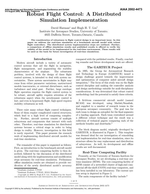
<strong>AIAA</strong> Modeling <strong>and</strong> Simulation Technologies Conference <strong>and</strong> Exhibit5-8 August 2002, Monterey, CaliforniaRobust Flight Control: A DistributedSimulation ImplementationDavid Harman ¤ <strong>and</strong> Hugh H. T. Liu y<strong>Institute</strong> for Aerospace Studies, University <strong>of</strong> Toronto.4925 Du®erin Street, Toronto,Ontario, CanadaThe consideration <strong>of</strong> robustness in °ight control design is an important issue. In thispaper we address the real-time simulation <strong>of</strong> a benchmark aircraft model with robust°ight controllers. The distributed system implementation steps are outlined. Further,a comparison <strong>of</strong> o²ine simulation results <strong>and</strong> published results is o®ered to verify thevalidity <strong>of</strong> the model to be implemented in the real-time environment. These results willbe used as the basis for future investigation <strong>of</strong> real-time simulations.<strong>AIAA</strong> 2002-4473IntroductionModern aircraft include a variety <strong>of</strong> automaticcontrol systems that aid the °ight in navigation,°ight management, <strong>and</strong> augmenting the stabilitycharacteristics <strong>of</strong> the airplane. The robustnessproblem, involved with the design <strong>of</strong> these °ightcontrol systems, is intended to deal with system uncertainties.These system uncertainties in °ight maycome from either parameter variations, unstructuredmodels inaccuracies, or external disturbance, such asturbulence <strong>and</strong> wind gust. Further, large envelope°ight operation requires the °ight control system tobe robust; aircraft agility requires attention <strong>of</strong> therobustness aspect when the aerodynamic control islost; <strong>and</strong> even in hypersonic °ight, high speed requiresstability robustness as well.There exist many robust °ight control techniques.Some <strong>of</strong> them require complicated control structures,which lead to a high level <strong>of</strong> computing complexity.Further, aircraft systems consist <strong>of</strong> multiplesubsystems <strong>and</strong> components that interact with eachother. Therefore, real-time simulation for distributedsystems become a critical stage in order to bringdesign to reality. However, investigation in this ¯eldis rarely reported. This paper presents the researchwork <strong>of</strong> implementing distributed aircraft models forreal-time simulation.The remainder <strong>of</strong> this paper is organized as follows.First, an introduction to the benchmark aircraft modelis given. The real-time computing facility is then described,followed by the discussion <strong>of</strong> the distributedmodel along with the implementation <strong>and</strong> modi¯cationsteps necessary for real-time simulation. Preliminaryo²ine simulation results are obtained to provide veri¯cation<strong>of</strong> the newly distributed model's accuracy¤ Graduate student, UTIASy Assistant Pr<strong>of</strong>essor, UTIAS, <strong>AIAA</strong> MemberCopyright c° 2002 by Hugh H.T. Liu. Published by the <strong>American</strong><strong>Institute</strong> <strong>of</strong> <strong>Aeronautics</strong> <strong>and</strong> Astronautics, Inc. with permission.compared with the published results. Finally, concludingremarks <strong>and</strong> future development work are o®ered.The GARTEUR ProjectIn 1995, the Group for Aeronautical Research<strong>and</strong> Technology in Europe (GARTEUR) issued adesign challenge geared towards the improvement<strong>and</strong> optimization <strong>of</strong> computer aided aircraft designintegration. 1 The focus <strong>of</strong> this study was on the °ightcontrol discipline <strong>and</strong> making the controller analysis<strong>and</strong> design methodology suitable for muli-disciplinaryconsiderations. It was determined that robust controlmethodology had the potential to satisfy these criteria.A ¯ctitious commercial aircraft model (namedRCAM) was developed, using Matlab/Simulink,<strong>and</strong> supplied to a number <strong>of</strong> research teams in theEuropean aerospace community. The goal was foreach team to design an autopilot for the ¯nal segments<strong>of</strong> a l<strong>and</strong>ing approach. Each team centralized arounda di®erent robust technique <strong>and</strong> the result was acollection <strong>of</strong> technical papers comparing each <strong>of</strong> themethods bene¯ts <strong>and</strong> drawbacks. 2The block diagram model, originally developed byGARTEUR, is illustrated in Figure 1. This templatewas deemed ideal for our investigation <strong>of</strong> remodeling<strong>and</strong> implementation for real-time simulation, since itsstructure allows for easy replacement <strong>and</strong> distribution<strong>of</strong> subsystems. As well, its development <strong>and</strong> o²ineresults are well documented.Real-Time Computing FacilityPresently, at the University <strong>of</strong> Toronto <strong>Institute</strong> forAerospace Studies, we are developing a real-time systemssimulator (RTSS). The core computing facility <strong>of</strong>RTSS consist <strong>of</strong> a networked cluster <strong>of</strong> high-end commercialo®-the-shelf (COTS) real-time computers, <strong>and</strong>has been installed in our laboratory. The current systemsetup is depicted in Figure 2.The main components <strong>of</strong> the facility include: 31 <strong>of</strong> 9<strong>American</strong> <strong>Institute</strong> <strong>of</strong> <strong>Aeronautics</strong> <strong>and</strong> Astronautics Paper 2002-4473Copyright © 2002 by the author(s). Published by the <strong>American</strong> <strong>Institute</strong> <strong>of</strong> <strong>Aeronautics</strong> <strong>and</strong> Astronautics, Inc., with permission.
system for hardware-in-the-loop simulation.² RTSS is also connected through a 1.25 Gbit/sGiganet to a similar facility to share data <strong>and</strong>resources.This real-time computing facility is suitable forour proposed distributed real-time simulation <strong>of</strong> thebenchmark aircraft model.Fig. 1GARTEUR Benchmark Model (RCAM)Distributed ModellingThe research objective <strong>of</strong> this project is to runreal-time distributed simulations on the RCAM modelwith di®erent robust °ight controllers, <strong>and</strong> to conducta comparative analysis.The interface s<strong>of</strong>tware that interprets the Matlab/Simulinkmodels <strong>and</strong> runs them on the real-timenodes is RT-LAB, developed by OPAL-RT Technologies.4 The original RCAM model was created usingMatlab (version 4.2) <strong>and</strong> Simulink (version 1.3), neither<strong>of</strong> which is supported by RT-LAB. Therefore, aninitial task is to upgrade the models <strong>and</strong> their correspondingcodes. This section details the changes thatwere made in order to prepare this model for real-timedistributed simulation.Model Sub-System SeparationThe original RCAM model (see Figure 1) was regroupedinto sub-systems as illustrated in Figure 3.Fig. 2UTIAS RTSS Facility² Three host computers each having dual-Pentiumprocessorsrunning Windows 2000 operating system.² Four real-time computers each having dual-Pentium-processors running Neutrino (QNX6)real-time operating system.² The real-time nodes are directly connected by400Mbit/sec FireWire <strong>and</strong> communicate with thehosts over a dedicated 100Mbit/s Ethernet network.² The system consists <strong>of</strong> 108 multiple channel IOFig. 3New RCAM Block DiagramThe model was grouped into the depicted subsystemsin a manner that best resembled a real aircraft,for the purposes <strong>of</strong> running distributed simulations.Each sub-system is described below:2 <strong>of</strong> 9<strong>American</strong> <strong>Institute</strong> <strong>of</strong> <strong>Aeronautics</strong> <strong>and</strong> Astronautics Paper 2002-4473
1. The trajectory generator is the ¯rst subsystem<strong>and</strong> it is a Matlab S-function which outputs aset <strong>of</strong> reference signals that the virtual aircraftmodel is to follow, as shown in Figure 4. The°ight is broken down into four segments (markedby A,B,C <strong>and</strong> D in Figure 4). The ¯rst segment(A) consists <strong>of</strong> a level °ight with a track angle <strong>of</strong>-90 degrees (west). An engine failure is simulatedpart way through this segment to investigate thelateral features <strong>of</strong> the robust controllers. The secondsegment (B) is a controlled 90 degree turn,to a track angle <strong>of</strong> zero degrees (north). Thethird segment (C) is a two-phase approach, ¯rstwith a comm<strong>and</strong>ed °ight path angle <strong>of</strong> -6 degreesfollowed by a comm<strong>and</strong>ed °ight path angle <strong>of</strong> -3degrees. Finally, in the last segment (D), the -3degrees °ight path angle is to be maintained duringa wind shear. The wind shear model is twodimensional <strong>and</strong> derived from. 52. The wind inputs <strong>and</strong> aircraft actuators aregrouped into a separate subsystem <strong>and</strong> are thoroughlyoutlined in the technical report TP-088-3<strong>of</strong> GARTEUR (AG08). 1 All system actuators areassumed to have ¯rst order system dynamics withrate limits <strong>and</strong> saturations. As well, all sensorsare assumed to be perfect.3. The next subsystem contains the nonlinear aircraftmodel. This is also a Matlab S-function <strong>and</strong>represents the aircraft's dynamic behavior as a set<strong>of</strong> equations.4. The controller is the next subsystem to be separated.The separation <strong>of</strong> the controller from therest <strong>of</strong> the model allows the incorporation <strong>of</strong> differentrobust controllers to be quite easy. The rest<strong>of</strong> the model can remain constant while only thecontroller algorithms are changed.5. The ¯nal subsystem is known as the console. Itconsists <strong>of</strong> all the outputs from the nonlinear aircraftmodel subsystem as well as the simulationclock. This subsystem is necessary for user interfacewhen implementing the model into RT-LAB<strong>and</strong> simulating in real-time.Controller ModelThe original RCAM model incorporated a robustcontroller that GARTEUR designed; it is outlined inthe technical report TP-088-9 <strong>of</strong> GARTEUR (AG08). 6This controller was used in our simulations solely forthe reason that the results <strong>of</strong> the original RCAM model(using this controller) are well documented. Theseresults provide a basis <strong>of</strong> comparison to verify the validity<strong>of</strong> our o²ine simulation results <strong>of</strong> the upgradedRCAM model. The design approach <strong>of</strong> the controlleris based on loop shaping using normalized coprimeFig. 4 Trajectory for the L<strong>and</strong>ing Approach <strong>of</strong> theRCAMfactorization. This method is based on H 1 synthesis<strong>and</strong> uses an uncertainty structure that does notrequire explicit uncertainty description. 7 Both the lateral<strong>and</strong> longitudinal controllers are broken down intoinner <strong>and</strong> outer loops. The purposes <strong>of</strong> the inner loopsare to stabilize <strong>and</strong> augment the h<strong>and</strong>ling qualities <strong>of</strong>the aircraft while the outer loop guides the aircraftalong the generated trajectory.Remodeling <strong>of</strong> RCAMAs mentioned earlier, some modi¯cations had to bemade to the original RCAM model in order for it tobe used in the RT-LAB real-time environment.S-functionsThe purpose <strong>of</strong> an S-function is to provide acomputer language description <strong>of</strong> a dynamic system.Two S-functions exist in the RCAM: the trajectorygenerator <strong>and</strong> the nonlinear aircraft dynamics block.Both <strong>of</strong> these were originally written in C-code forSimulink (Version 1.3).The upgrading <strong>of</strong> these S-functions took place in twophases. The ¯rst phase was to reprogram them as Matlabscript ¯les (¯le extension .m). The second phasewas to reprogram the original RCAM S-functions in C-code in accordance with the upgraded stipulations <strong>of</strong>Simulink (Version 3). 8 The C-code S-functions werethen converted into Matlab executable ¯les (CMEX¯les) which are recognized by Simulink.RT-LAB Model Con¯gurationFigure 3 illustrates the proper format for which aSimulink model must be grouped in order for RT-LABto acknowledge it. The RT-LAB s<strong>of</strong>tware groupsmodels into three di®erent categories: slave blocks3 <strong>of</strong> 9<strong>American</strong> <strong>Institute</strong> <strong>of</strong> <strong>Aeronautics</strong> <strong>and</strong> Astronautics Paper 2002-4473
Fig. 5Segment AFig. 7Segment CFig. 6Segment BFlight Segment C ComparisonFigure 7 shows the di®erences between the M-¯le<strong>and</strong> CMEX-¯le RCAM third segment o²ine simulations.Once again, as in the second segment, both theM-¯le <strong>and</strong> CMEX-¯le simulation results are almostidentical with an error that is to small to be considered.Flight Segment D ComparisonFigure 8 shows the di®erences between the M-¯le<strong>and</strong> CMEX-¯le RCAM ¯nal segment o²ine simulations.This plot uses the same variables as in the segment Cplot (x-position <strong>and</strong> altitude). Once again, the resultsFig. 8Segment Dreveal no signi¯cant error between the two simulations.Evaluation CriteriaAccording to the technical report TP-088-3 <strong>of</strong>GARTEUR (AG08), 1 each designed robust °ightcontroller will be evaluated by several criteria to\obtain an objective comparison between completelydi®erent controllers". Therefore, we will validateour remodeled RCAM model by checking the samecriteria. The tested controller is designed usingeigenstructure assignment <strong>and</strong> four test cases areconducted: (1) nominal case, (2) CG fwd case wherethe horizontal center <strong>of</strong> gravity has been shifted tothe most forward position, (3) CG aft case where theCG is shifted to the most afterward position, <strong>and</strong>5 <strong>of</strong> 9<strong>American</strong> <strong>Institute</strong> <strong>of</strong> <strong>Aeronautics</strong> <strong>and</strong> Astronautics Paper 2002-4473
(4) time delay case where the °ight is executed witha nominal center <strong>of</strong> gravity <strong>and</strong> a time delay <strong>of</strong> 100 ms.Five quantitative criteria are given for each segment(A, B, C, D) <strong>of</strong> the °ight path:² performance;² quality;² safety;² control; <strong>and</strong>Table 1Segment A Criteria ComparisonCases P A Q A S A C A R AGARTEUR 0.0764 0.5432 0.0038 0.0037 0.0309nominal 0.0766 0.5482 0.0041 0.0031CG fwd 0.0743 0.5269 0.0104 0.0031CG aft 0.0792 0.5744 0.0091 0.0032delay 0.0794 0.5770 0.0096 0.0032average 0.0774 0.5566 0.0083 0.0032 0.0347² robustnessSegment A Criteria EvaluationThe performance criterion de¯nes the lateral deviationboundary <strong>of</strong> 20m to account for the e®ect <strong>of</strong>turbulence, <strong>and</strong> the boundary <strong>of</strong> 100m during enginefailure:P A = 1 ³2maxeyb (t)t 0·t·t a 100 + e yb(t a )´(1)20where e yb (t) denotes the lateral deviation in bodycoordinates.The quality criterion considers the maximum lateralacceleration <strong>of</strong> 0:2g:Q A =³ ny (t)´maxt 0·t·t a 0:2(2)The safety criterion sets the limit <strong>of</strong> the maximumangle <strong>of</strong> attack ® <strong>of</strong> 12 deg:S A =³ j®(t)j´3maxt 0·t·t a 12(3)The control criterion concerns the rudder actuatore®ort to stabilize the aircraft after engine failure isrecovered:C A =Z tat 0± 2 R dt (4)The maximum di®erence between the lateral deviation<strong>of</strong> the trajectories with nominal <strong>and</strong> perturbedcenter <strong>of</strong> gravity (CG forward, CG backward) <strong>and</strong> withthe time delay is de¯ned as:³´¢ eyb (t) = max je ybmax (t)¡e yb (t)j; je ybmin (t)¡e yb (t)j(5)<strong>and</strong> the robustness criterion sets the limit <strong>of</strong> maximalallowable deviations <strong>and</strong> the limit at the end <strong>of</strong> thissegment:R A = 1 2³ max¢eyb (t)t 0·t·t a 10+ ¢ eyb(t a )´2(6)The o®-line simulation results <strong>of</strong> Segment A comparedwith the published results are shown in Table 1<strong>and</strong> Figure 9.Fig. 9 Segment A Criteria Evaluation: Case (1)- nominal, (2) - CG fwd, (3) - CG aft, (4) - delay,(5) - averageSegment B Criteria EvaluationThe performance criterion de¯nes the maximum lateraldeviation <strong>of</strong> 200m due to the turn <strong>and</strong> the lateraldeviation <strong>of</strong> 20m at the end <strong>of</strong> the segment:P B = 1 2³ maxeyb (t)t a·t·t b 200 + e yb(t b )´20(7)The quality criterion considers the maximum lateralacceleration <strong>of</strong> 0:02g:Q B =³ ny (t)´maxt a·t·t b 0:02(8)The safety criterion sets the limit <strong>of</strong> the maximumangle <strong>of</strong> attack ® <strong>of</strong> 12 deg:S B =³ j®(t)j´3maxt a·t·t b 12(9)The control criterion concerns the rudder <strong>and</strong>aileron actuator e®ort:Z tb ³ ´C B = ± R 2 + ± A2 dt (10)t aThe robustness sets the limit <strong>of</strong> maximal allowablelateral deviations with perturbed center <strong>of</strong> gravity <strong>and</strong>6 <strong>of</strong> 9<strong>American</strong> <strong>Institute</strong> <strong>of</strong> <strong>Aeronautics</strong> <strong>and</strong> Astronautics Paper 2002-4473
time delays:R B = 1 2³ max¢eyb (t)t a·t·t b 20+ ¢ eyb(t a )´2(11)The o®-line simulation results <strong>of</strong> Segment B comparedwith the published results are shown in Table 2<strong>and</strong> Figure 10.Table 2Segment B Criteria ComparisonCases P B Q B S B C B R BGARTEUR 0.4964 0.7340 0.0382 0.0027 0.0161nominal 0.6090 0.7095 0.0302 0.0024CG fwd 0.6092 0.6925 0.0374 0.0024CG aft 0.6086 0.7332 0.0236 0.0025delay 0.6086 0.7356 0.0239 0.0025average 0.6089 0.7177 0.0288 0.0025 0.0156The control criterion concerns the tailplane actuatore®ort:Z tcC C = ± T 2 dt (15)t bThe robustness sets the limit <strong>of</strong> maximal allowablevertical deviations with perturbed center <strong>of</strong> gravity<strong>and</strong> time delays:R C = 1 ³2max¢ezb (t)+ ¢ ezb(t c )´(16)t b·t·t c 2 0:6The o®-line simulation results <strong>of</strong> Segment C comparedwith the published results are shown in Table 3<strong>and</strong> Figure 11.Table 3Segment C Criteria ComparisonCases P C Q C S C C C R CGARTEUR 0.3285 1.1808 0.0070 0.0150 0.4926nominal 0.3475 1.1907 0.0078 0.0160CG fwd 0.3759 1.2080 0.0109 0.0261CG aft 0.3268 1.1757 0.0054 0.0084delay 0.3271 1.1774 0.0054 0.0084average 0.3443 1.1880 0.0074 0.0147 0.5034Fig. 10 Segment B Criteria Evaluation: Case (1)- nominal, (2) - CG fwd, (3) - CG aft, (4) - delay,(5) - averageSegment C Criteria EvaluationThe performance criterion considers the maximumvertical deviation during the capture <strong>of</strong> the ¡6 degreeglide slope <strong>and</strong> the vertical deviation at the end <strong>of</strong>this segment. Further, speed variations should be keptsmall in spite <strong>of</strong> the change in required angle <strong>of</strong> attack:P C = 1 ³3maxezb (t)+ e zb(t c )+ jV ¡ V comm<strong>and</strong>jt b·t·t c 20 64(12)The quality criterion considers the maximum verticalacceleration:³ nz (t)´Q C = max(13)t b·t·t c 0:05The safety criterion sets the limit <strong>of</strong> the maximumangle <strong>of</strong> attack ® <strong>of</strong> 12 deg:S C =³ j®(t)j´3maxt b·t·t c 12´(14)7 <strong>of</strong> 9Fig. 11 Segment C Criteria Evaluation: Case (1)- nominal, (2) - CG fwd, (3) - CG aft, (4) - delay,(5) - averageSegment D Criteria EvaluationThe performance criterion considers the maximumvertical deviation due to the wind shear <strong>and</strong> the verticaldeviation at the end <strong>of</strong> this segment:P D = 1 2³ maxezb (t)t c·t·t d 20+ e zb(t d )1:5´(17)The quality criterion considers the maximum verticalacceleration:³ nz (t)´Q D = max(18)t c·t·t d 0:2<strong>American</strong> <strong>Institute</strong> <strong>of</strong> <strong>Aeronautics</strong> <strong>and</strong> Astronautics Paper 2002-4473
Table 6 Average Error Comparison Table <strong>of</strong> NominalTest CaseNominal Case Criteria AVRSeg A P A 0.26%Q A 0.92%S A 7.89%C A 16.22%R ASeg B P B 22.68%Q B 3.34%S B 20.94%C B 11.11%R BSeg C P C 5.78%Q C 0.84%S C 11.43%C C 6.67%R CSeg D P D 3.04%Q D 30.83%S D 6.96%C D 3.24%R D2 Magni, J.-F., Bennani, S., <strong>and</strong> Terlouw, J., Robust FlightControl: A Design Challenge, Springer-Verlag, 1997.3 Liu, H., \Real-Time System Simulation using COTS for°ight cotnrol integration," <strong>AIAA</strong> Modeling <strong>and</strong> SimulationTechnologies Conference & Exhibit, August <strong>AIAA</strong> Paper A01-37308,2001.4 The Opal-RT Technologies Inc., RT LAB 4.2 User's Guide,September 2000.5 Robinson, P., \The Modeling <strong>of</strong> Turbulence <strong>and</strong> Downburstsfor Flight Simulators," Tech. Rep. # 339, UTIAS, 1991.6 GARTEUR, \RCAM Preliminary Design Document," Tech.Rep. TP-088-9, Group for Aeronautical Research <strong>and</strong> Technologyin Europe (GARTEUR), Action Group FM (AG08), 1995.7 Francis, B., A Course in H 1 Control Theory, Springer-Verlag, 1987.8 The Mathworks Inc., Writing S-Functions (Version 3), October1998.9 Harman, D. <strong>and</strong> Liu, H., \Robust Flight Control: A Real-Time Simulation Investigation," International Council <strong>of</strong> theAeronautical Sciences (ICAS), May (accepted on 18-Oct-2001),2002.this upgraded RCAM model matched the simulationresults <strong>of</strong> the original RCAM model. 6 The comparisonbetween the CMEX-¯le <strong>and</strong> M-¯le RCAM simulationmodels brought to light the realization that theformer runs approximately 20 times faster, in terms<strong>of</strong> clock time. With minor exception <strong>of</strong> the ¯rst°ight segment results (showing small discrepanciesin °ight path), each <strong>of</strong> segments B, C <strong>and</strong> D showedinsigni¯cant error between the M-¯le <strong>and</strong> CMEX-¯leo²ine simulations. It is obvious, from the results<strong>of</strong> this paper, that the CMEX-¯le RCAM model isthe superior choice for simulation. Further, o®-linesimulation results have been analyzed extensively,based on the evaluation criteria. Comparison workshows satisfactory results as well.The next step, in this area <strong>of</strong> research, is to implementthe CMEX-¯le RCAM model into the realtime environment using RT-LAB. Real-time simulationsneed to be conducted to evaluate the designcriteria. Comparison work will also be performed betweeno®-line results <strong>and</strong> real-time results <strong>and</strong> amongdi®erent robust controllers. It is beyond the scope <strong>of</strong>this paper <strong>and</strong> is the topic presented in another paper.9References1 GARTEUR, \Robust Flight Control Design Challenge ProblemFormulation <strong>and</strong> Manual: The Research Civil AircraftModel (RCAM)," Tech. Rep. TP-088-3, Group for AeronauticalResearch <strong>and</strong> Technology in Europe (GARTEUR), ActionGroup FM (AG08), 1997.9 <strong>of</strong> 9<strong>American</strong> <strong>Institute</strong> <strong>of</strong> <strong>Aeronautics</strong> <strong>and</strong> Astronautics Paper 2002-4473