
Create successful ePaper yourself
Turn your PDF publications into a flip-book with our unique Google optimized e-Paper software.
TABLE OF CONTENTS1. INTRODUCTION................................................................... 42. TECHNICAL SPECIFICATIONS ....................................... 53. FEATURES ............................................................................. 94. THEORY OF OPERATION ............................................... 234.1. INTRODUCTION ...........................................................................234.2. DIGITAL CIRCUITS ......................................................................234.3. RF CIRCUITS.................................................................................274.3.1. PLL SYNTHESIZER ................................................................................ 274.3.2. TRANSMITTER ....................................................................................... 284.3.3. RECEIVER .............................................................................................. 294.4. ACC-513 (GMSK MODEM CIRCUITS)........................................314.5. ACC-514 (FFSK MODEM CIRCUITS) .........................................324.6. ACC-515 (GPS INTERFACE CIRCUITS) .....................................335. MAINTENANCE AND REPAIR........................................ 346. COMPONENT REPLACEMENT ...................................... 387. ALIGNMENT PROCEDURE ............................................. 407.1. RECEIVER......................................................................................417.2. TRANSMITTER ..............................................................................427.3. SQUELCH ADJUSTMENT ............................................................437.4. TEST EQUIPMENT SETUP ..........................................................452
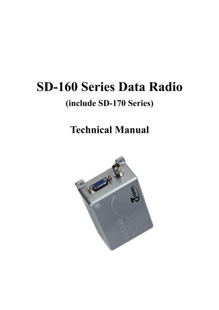
1. INTRODUCTIONThe <strong>SD</strong>-<strong>160</strong> and <strong>SD</strong>-170 <strong>Series</strong> (hereinafter called “the radios”) of RF wirelessmodems from MAXON utilize the latest technology in its design and manufacturing. Boththe UHF and VHF models are Phase Lock Loop Synthesizer (PLL) / microprocessorcontrolled and offer two watts (<strong>SD</strong>-<strong>160</strong> <strong>Series</strong>) or one to five watts (<strong>SD</strong>-170 <strong>Series</strong>) ofpower with 16-channel capability. Multiple functions including 1200 to 9600 baud rates,AC and/or DC audio coupling, GMSK, FFSK and FSK modulation are standard in thesefully programmable wide bandwidth RF wireless modem units. Programmable sub-audiosquelch system (CTCSS & DCS) and two-tone squelch system are newly added to thesignal level detect squelch system (RSSI). GPS <strong>Data</strong> handling is provided to interfaceand control internal GPS receiver.The radios are programmed using an IBM ® Personal Computer, DOS ® or WINDOWS ®based software, an interface module and a programming cable. This allows the radio tobe tailored to meet the requirements of the individual user and of the System(s) it isoperating within.4
2. TECHNICAL SPECIFICATIONSGENERALVHFUHFEquipment Type : <strong>Data</strong> radio (Wireless Modem) <strong>Data</strong> radio (Wireless Modem)Model <strong>Series</strong> : <strong>SD</strong>-161 <strong>SD</strong>-171 <strong>SD</strong>-164 <strong>SD</strong>-174Performance Specifications : TIA/EIA-603 ETS 300-113 TIA/EIA-603 ETS 300-113Frequency Range : 148-174MHz 148-174MHz 450-490MHz 450-490MHzRF Output : 2W Only 1-5W 2W Only 1-5WChannel Spacing :12.5KHz, 25KHz ProgrammableModulation Type :F3D, F3EIntermediate Frequency :45.1MHz & 455KHzNumber of Channels : 16Frequency Source :SynthesizerOperation Rating :Intermittent90 : 5 : 5 (Standby : RX : TX)Power Supply :Ext. Power Supply (12 VDC Nominal)Temperature Range :StorageOperatingFrom -40°C to +80°CFrom -30°C to +60°CCurrent Consumption :Standby(Muted)Transmit 5Watts RF PowerTransmit 2Watts RF Power< 65mA< 2.0 A< 1.0 ALock Time :< 10msTX to RX attack time :< 20ms (No Power Saving)RX to TX attack time :< 20msDimensions :(32mm)H X (58mm)W X (125mm)DWeight :253 grams5
TRANSMITTERVHFUHFModel <strong>Series</strong> : <strong>SD</strong>-161 <strong>SD</strong>-171 <strong>SD</strong>-164 <strong>SD</strong>-174Carrier Power : (Nom. Max. Min.)Hi PowerLow Power2W < 3W > 1.5WN/A5W < 6W > 4.5W1W0.8W2W < 3W > 1.5WN/A5W < 6W > 4.5W1W0.8WSustained Transmission :Time : 5 10 30SecPower : >90% >85% >80% Power : >90% >85% >80%(Nominal Conditions)Frequency Error :Nominal conditionExtreme condition< 0.5 KHz±5.0 ppm< 0.75 KHz±5.0 ppmFrequency Deviation :25 KHz Channel Spacing12.5 KHz Channel SpacingPeak ±5.0, Min. ±3.8Peak ±2.5, Min. ±1.9Audio Frequency Response :Within +1/-3dB of 6dB octave@ 300 Hz to 2.55 kHz for 12.5 kHz C.S.@ 300 Hz to 3.0 kHz for 25 kHz C.S.Adjacent Channel Power :25 KHz Channel Spacing12.5 KHz Channel Spacing< 70 dBc @ Nominal Condition , < 65 dBc @ Extreme Condition< 60 dBc @ Nominal Condition , < 55 dBc @ Extreme ConditionConducted Spurious Emission : < -60 dBc < -30 dBm < -60 dBc < -30 dBmModulation Sensitivity :100mV RMS @ 60% Peak Dev.Hum & Noise :25 KHz Channel Spacing12.5 KHz Channel Spacing> 40 dB (without PSOPH)> 40 dB (with PSOPH)Modulation Symmetry :< 10% Peak Dev @ 1KHz input for nominal dev. + 20dBLoad Stability :No osc at ≥ 10:1 VSWR all phase angles and suitable antennaNo destroy at ≥ 20:1 all phase anglePeak Deviation Range Adjustment@ 1 KHz, Nom Dev + 20dB :25 KHz Channel Spacing12.5 KHz Channel SpacingMin. 3.5, Max. 6.0Min. 1.5, Max. 4.06
RECEIVERVHFUHFModel <strong>Series</strong> : <strong>SD</strong>-161 <strong>SD</strong>-171 <strong>SD</strong>-164 <strong>SD</strong>-174Sensitivity (@ 12dB SINAD) :25 KHz Channel Spacing12.5 KHz Channel SpacingSensitivity ( 1/100 Error Rate)With ACC-513With ACC-514< 0.28uV< 0.30uV< -113dBm< -110dBm< 0.28uV< 0.30uV< -113dBm< -110dBm< 0.28uV< 0.30uV< -113dBm< -110dBmAmplitude Characteristic : > -3dB , < +3dB > -3dB , < +3dBAdjacent Channel Selectivity :25 KHz Channel Spacing(Nom.)(Extreme Condition)12.5 KHz Channel Spacing(Nom.)(Extreme Condition)> 65 dB> 55 dB> 55 dB> 45 dB> 70 dB> 60 dB> 60 dB> 50 dB> 65 dB> 55 dB> 55 dB> 45 dB< 0.28uV< 0.30uV< -113dBm< -110dBm> 70 dB> 60 dB> 60 dB> 50 dBSpurious Rejection(100KHz ~ 4GHz) > 60 dB > 70 dB > 60 dB > 70 dBImage / Half IF Rejection : > 60 dB > 70 dB > 60 dB > 70 dBIntermodulation Response Rejection±25 kHz/ 50 kHz±50 kHz/ 100 kHzConducted Spurious Emission :9 KHz - 1 GHz1 GHz – 4 GHzRX Spurious Emissions (Radiated) :9 KHz - 1 GHz1 GHz – 4 GHzAF Distortion :Nominal conditionExtreme conditionRX Hum & Noise (only audio) :25 KHz Channel Spacing12.5 KHz Channel Spacing> 60 dB> 60 dB< 5%< 10%< -57 dBm< -47 dBm< -57 dBm< -47 dBm> 70 dB> 70 dB< 3%< 10%< 40 dB without PSOPH< 40 dB with PSOPH> 60 dB> 60 dB< 5%< 10%< -57 dBm< -47 dBm< -57 dBm< -47 dBm> 70 dB> 70 dB< 3%< 10%< 40 dB without PSOPH< 40 dB with PSOPHReceiver Response Time : < 16 ms < 16 msSquelch (factory pre-set)OpenCloseSquelch Attack Time :RF Level at ThresholdRF Level at Threshold + 20dBSquelch Decay Time :Antenna Socket Input MatchTemperature Stability forL.O. Frequency :L.O. Frequency Aging Rate :-113dBm-116dBm< 20 ms (RSSI), < 40 ms (Analog)< 10 ms (RSSI), < 30 ms (Analog)5 ms Min., 20ms Max.> 10 dB Return Loss1st < 5 ppm, 2nd < 15 ppm from -30° to + 60° C±2 ppm/ year7
3. FEATURES16 ChannelsThe <strong>SD</strong>-<strong>160</strong> <strong>Series</strong>(include <strong>SD</strong>-170 <strong>Series</strong>, hereinafter called “<strong>SD</strong>-<strong>160</strong>”) radio can store up to 16channels within the same band. These channels can be selected by inner DIP-S/W or serialcommand inputted from external control system.Channel SpacingThe <strong>SD</strong>-<strong>160</strong> is capable of programmable channel spacing, in both UHF and VHF bands. Eachchannel can be programmed via the PC programmer, ACC-916, having 12.5KHz or 25KHzchannel spacing.Output PowerIn case of <strong>SD</strong>-<strong>160</strong>, 2-Watts output power is only available, but, in <strong>SD</strong>-170, it’s programmable.Each channel can be programmed via the PC programmer to a high-power output, 5 Watts, anda low-power output, 1 Watt.Channel ScanFor audio application, <strong>SD</strong>-<strong>160</strong> supports channel scan enabled via serial commands. Duringprogramming of the radio, any channel can be selected as a scanned channel. When a scannedchannel is selected, it becomes a part of the scan list. Once the scan list has been established,initiates scan by serial commands. If a conversation is detected on any of the channels in thescan list, the radio will stop on that channel and audio signal will be released through pin 9 ofthe DB-15 connector. At that moment, busy channel data is sent to external equipment ordevice through serial command. So, busy channel data can be identified as decoding receivedserial command from radio in the external equipment or device. Normally, if user tries to transmitduring scanning, the transmission will be made on the channel that the call is received duringthe programmable scan delay time. (The scan delay time is the amount of time the radio willstay on that channel once working has ceased. Dealer programming of 4 ~ 7 seconds is typical).The radio will resume scanning once the scan delay time has passed, and will continue to scanuntil the serial command for scan stop is inputted by external equipment. After the scan hasresumed, if a transmission is made, the radio will transmit on the selected priority channel. Thisfeature is similar to priority scan TX except for selection of priority channel. You can assign apriority channel by inner dip switch only.9
Scan DeleteTo temporarily delete a channel from the scan list, simply input the serial command for scandeletion to the radio while scanning and stopped on the channel to be deleted. This willtemporarily remove that channel from the scan list until the scan is closed or the radio’s power isreset.CTCSS / DCS ScanningTo help to block out unwanted calls to your radio, the <strong>SD</strong>-<strong>160</strong> series can be programmed byyour dealer to scan for tones.Busy Channel LockoutThis feature, when enabled, disables the transmitter when the user would attempt to transmitduring the receiving channel is busy. It will be dealer-programmable on/off and applicable to allchannels.Marked IdleWhen used in conjunction with Busy Channel, lockouted transmitter is allowed to operate aslong as valid RX tone is received. Dealers program this feature as ON or OFF. This feature willbe dealer-programmable on/off and applicable to all channels.TX Time-outThis feature, when enabled, limits the amount of time that the user can continuously transmit.This time can be set in increments by 10 seconds from 10 seconds to 990 seconds. If the userattempts to transmit longer than the TX Time-out period, five seconds prior to expiration, theradio will release Time-out alert signal through pin 9 of the DB-15 connector and will ceasetransmission.Power SaveThe function of Power Save is used when an external battery is used as the power source.When Power Save is enabled, the receiver ON and OFF time can be programmed and allowsthe operator to set the length of time the receiver gets asleep.Tx DelayThe TX will remain active for 150 ms at the end of TX when using CTCSS tones. This eliminatessquelch tail. Dealer programs this feature as ON or OFF.10
Squelch OptionsCompared to existing Maxon data radios, programmable sub-audio squelch system (CTCSS &DCS) and two-tone squelch system are newly added. Each channel will have these squelchoption sets during dealer programming. More detail descriptions for all available squelchsystems of <strong>SD</strong>-<strong>160</strong> are the following.Sub-audio squelch systemThe <strong>SD</strong>-<strong>160</strong> can operate singly or with optional modem boards. Even if user wants to use subaudioSQ system, the radio will permit this SQ option according to some cases to avoidconfliction between sub-audio and data.Contrary to general-purpose two-way radio, the input of the radio is data or audio. In case ofaudio, its frequency spectra are limited to 300Hz ∼ 3kHz by internal BPF. So, the division of thisand sub-audio is possible on the frequency spectra because sub-audio has under 300Hzfrequency. But, <strong>Data</strong> has wide frequency spectra compared with audio. Normally, that has 30Hz∼ 4.8kHz frequency (except harmonic freq.) at 9600 baud rate. Accordingly, the conflict of subaudioand data are inevitable and so broken data or SQ error is unavoidable. To solve thisproblem, the radios can use the FFSK modulation which converts data into two differentcontinuous audio tone according to their logic levels. Therefore, available cases of sub-audioSQ system are Audio and FFSK signal. But, it’s not permitted to FSK(FM direct modulation ofdata) and GMSK signal.a.Single operation of <strong>SD</strong>-<strong>160</strong>If the radio operates singly, only FM direct modulation/demodulation of audio and data areavailable. In this case, audio and data are inputted and released through different DBconnector lines which pin 7, 9, 1 and 2 of DB-15 connector are used as audio input, audiooutput, data input and data output, respectively. Normally, Sub-audio Squelch(SQ) Systemcan be applied to audio signal, but data doesn’t use it to avoid frequency confliction. So, ifuser tries to transmit data in one channel which has sub-audio squelch option, radio willflash green LED two times as warning and then transmit it without sub-audio.Note : <strong>SD</strong>-<strong>160</strong> provides the connection of external modems to receive and transmitexternal modulated data which can be inputted and outputted through pin 1 and 211
of DB-15 connector, respectively. In this case, the external signals are referencedto ground and may be a.c. or d.c. coupled depending on the user requirement.Especially, if the type of external modem is AFSK or FFSK, Sub-audioSquelch(SQ) System can be applied by dealer programming. For reference, itsrelated parameter is “Tx Tone Generation for <strong>Data</strong> Input” of “Tx option” groupon the “System Option / GPS” tap window of ACC-916.Brief block signal flow diagrams for each input are the following (See Figure 2.1. ~ 2.3.).RF BoardAudio Amp. & FilterPre-emphasisLevelDetectorAudio InPre-SelectorAFRSSIIF ICTA31136FNHigh : Audio InLow : No AudioZ0Z1ZMod OutZ0Z1ZLM386Audio OutY0Y1X0X1YX300Hz HPF<strong>Data</strong> BPFY0Y1X0X1YX300Hz HPFAudio MuteAudio Amp.Analog S/WMC14053BMF6Sub-Audio LPFAdj. LevelAnalog S/WMC14053BMF6Sub-Audio LPF4th OrderSub-Audio LPFCheck Audio InSub-AudioEncoderMCUTone EnRSSIBusyAudio MuteMCUTone DetectorMF6ComparatorAudio signal flow in TransmitterAudio signal flow in ReceiverFigure 3.1. Audio signal flow diagramRF BoardLevelDetector<strong>Data</strong> InAudio InAFRSSIIF ICTA31136FNHigh : Audio InLow : No Audio<strong>Data</strong> BPFMod Out30Hz ~ 5KHzBPFComparator<strong>Data</strong>OutCheck Audio In<strong>Data</strong> EnableMCUIf audio input is absent,<strong>Data</strong> path will be enabled.In this case,Sub-audio option is ignored.BusyRSSIMCU<strong>Data</strong> signal flow in Transmitter<strong>Data</strong> signal flow in Receiver12
Figure 3.2. <strong>Data</strong> signal flow diagramRF BoardLevelDetector<strong>Data</strong> InAudio InPre-SelectorAFRSSIIF ICTA31136FNHigh : Audio InLow : No AudioZ0Z1ZMod OutZ0Z1Z30Hz ~5KHzAudio OutY0Y1Y<strong>Data</strong> BPFY0Y1YBPFX0X1XX0X1XAnalog S/WMC14053BMF6Sub-Audio LPFAdj. LevelAnalog S/WMC14053BMF6Sub-Audio LPF4th OrderSub-Audio LPF<strong>Data</strong> EnableCheck Audio InSub-AudioEncoderMCUTone EnRSSIMCUBusyTone DetectorMF6ComparatorExt. Mod. signal flow in TransmitterExt. Mod. signal flow in ReceiverFigure 3.3. External modulated signal flow diagramb. FFSK & GMSKMaxon provides two optional modem boards, ACC-513, GMSK and ACC-514, FFSK for<strong>SD</strong>-<strong>160</strong> to improve the efficiency for data transmission and offer maximum flexibility foruser application. Selection of the required modulation option is made installing wantedmodem to radio and programming several modem parameters through PC-programmer,ACC-916. Modem board provides the facility to connect a computerized controller via anRS-232 level serial data interface (i.e. Communication port COM1, COM2, etc. for PCs) toits Slave MCU. Received data from controller(DTE) will then drive the FFSK or GMSKmodulator and allow transmission of serial data. It also provides FFSK or GMSKdemodulator for the reception of FFSK or GMSK modulated data signals. These areconverted to RS-232 level serial data stream for supply to a computerized controller.In application of Sub-audio squelch, it can’t apply to GMSK modulated signal because oftheir frequency confliction. But, FFSK modulated signal can be mixed with sub-audiobecause it consists of two different continuous tones which frequency spectra are on theaudio frequency region.Brief block signal flow diagrams for each optional modem board are the following (SeeFigure 2.4. and Figure 2.5.).13
RF BoardPre-SelectorAFRSSIIF ICTA31136FNZ0Z1Y0Y1ZY<strong>Data</strong> BPFMod OutZ0Z1ZX0X1XY0Y1YAnalog S/WMC14053BMF6Sub-Audio LPFTone EnAdj. LevelX0X1XAnalog S/WMC14053BMF6Sub-Audio LPF4th OrderSub-Audio LPFMaster MCUBusySub-AudioEncoderRx_EnTx_EnTone DetectorRSSIMaster MCUMF6ComparatorFFSK ModemOption BoardSlave MCURx_EnTx_EnTx_Signal(CMX469A)Tx_CLKTxCTx_<strong>Data</strong>_OutTDORx_CLKRx_<strong>Data</strong>_InRxCRDISerial <strong>Data</strong> InSerial <strong>Data</strong> InFFSK ModemOption BoardRx_Signal(CMX469A)Tx_CLKTxCTx_<strong>Data</strong>_OutTDORx_CLKRx_<strong>Data</strong>_InSlave MCURxCRDISerial <strong>Data</strong> OutSerial <strong>Data</strong> OutFFSK signal flow in Transmitter FFSK signal flow in ReceiverFigure 3.4. FFSK signal flow diagramRF Board<strong>Data</strong> BPFMod OutAFRSSIIF ICTA31136FNMaster MCURx_EnTx_EnSub-audio option is ignored.RSSIBusyMaster MCURx_EnGMSK ModemOption BoardSlave MCUTx_EnTx_Signal(CMX589A)Tx_CLKTxCTx_<strong>Data</strong>_OutTDORx_CLKRx_<strong>Data</strong>_InRxCRDISerial <strong>Data</strong> InSerial <strong>Data</strong> InGMSK ModemOption BoardRx_Signal(CMX589A)Tx_CLKTxCTx_<strong>Data</strong>_OutTDORx_CLKRx_<strong>Data</strong>_InSlave MCURxCRDISerial <strong>Data</strong> OutSerial <strong>Data</strong> OutGMSK signal flow in Transmitter GMSK signal flow in ReceiverFigure 3.5. GMSK signal flow diagram14
c. CTCSS signal informationEach channel supports the 38 TIA/EIA standard tone frequencies and 11 non-standardtones. All tones will be set up during dealer programming.No. Freq.(Hz)No. Freq.(Hz)No. Freq.(Hz)No. Freq.(Hz)No. Freq.(Hz)01 67.0 11 97.4 21 136.5 31 192.8 41 171.302 71.9 12 100.0 22 141.3 32 203.5 42 177.303 74.4 13 103.5 23 146.2 33 210.7 43 183.504 77.0 14 107.2 24 151.4 34 218.1 44 189.905 79.7 15 110.9 25 156.7 35 225.7 45 196.606 82.5 16 114.8 26 162.2 36 233.6 46 199.507 85.4 17 118.8 27 167.9 37 241.8 47 206.508 88.5 18 123.0 28 173.8 38 250.3 48 229.109 91.5 19 127.3 29 179.9 39 69.3 49 254.110 94.8 20 131.8 30 186.2 40 159.8Table 3.1. CTCSS Frequency Chartd. DCS signal informationThe radio supports the encoding and decoding of 104 DCS data (include TIA/EIA code).OctalCodeOctalCodeOctalCodeOctalCodeOctalCodeOctalCodeOctalCodeOctalCodeOctalCodeOctalCodeOctalCode023 054 125 165 245 274 356 445 506 627 732025 065 131 172 246 306 364 446 516 631 734026 071 132 174 251 311 365 452 523 632 743031 072 134 205 252 315 371 454 526 654 754032 073 143 212 255 325 411 455 532 662036 074 145 223 261 331 412 462 546 664043 114 152 225 263 332 413 464 565 703047 115 155 226 265 343 423 465 606 712051 116 156 243 266 346 431 466 612 723053 122 162 244 271 351 432 503 624 731Table 3.2. DCS Code Chart15
Two-Tone Squelch(SQ) SystemThe radios will support Motorola-Format, Two-Tone(Type 99) decoding. This is receive only,decode only feature. It will allow a dispatcher to call individuals and groups. EachSystem/Group will be programmable to respond to any combination of the code, with adistinctive alert for each System/Group. The alert format consists of two tone sequences, firstthe ID of the radio being called, then the ID of the calling radio.This feature is programmed by the dealer(per customer’s request) and is not activated /deactivated by the user. The user interface consists of the radio emitting the tones beingbroadcast. At this point, the radio will enter Unmuted Rx mode and remain in this mode until thePTT signal is inputted.Serial commandTo give the simplest protocol for control of radio, Maxon has prepared for some serialcommands which have an ease to encode and decode format. <strong>SD</strong>-<strong>160</strong> can be used withoutserial commands, but user can use its various functions through application of those, forinstance, setting-up the basic radio operation such as channel change, switch of RX/TX andchannel scan, moreover, used for control of GPS and modem option board. All messages are inbinary format, which reduces required data size to shorten response time of radio and followsbelow data format.Serial RX/TX <strong>Data</strong> Format(1) Asynchronous Serial <strong>Data</strong> Transfer(2) Baud Rate : 4,800 bit/sec(3) <strong>Data</strong> Bit : 8bit , Non Parity(4) Stop Bit : 1bit(5) MSB first transmissionEach serial command is consist of 3 bytes. 1 st byte is command and 2 nd is data required bycommand and 3 rd is check sum to decide validity of total contents.Byte0ST 1 st Byte (Command) SPByte1ST 2 nd Byte (<strong>Data</strong>) SPByte2ST 3 rd Byte (Check Sum) SP16
<strong>Data</strong> Protocola. Protocol for input serial commandProtocol of data transmission from external equipment or device (: PC) to radio :External equipment or device<strong>Radio</strong>Input serial commandResponseReceive responseFigure 3.6. Protocol for input serial commandb. Protocol for output dataProtocol of data transmission from radio to external equipment or device (: PC) :External equipment or device<strong>Radio</strong>Receive <strong>Data</strong>Output <strong>Data</strong>(with command)Receive <strong>Data</strong>Output <strong>Data</strong>(with command)Figure 3.7. Protocol for output dataDetail information of Serial Commandsa. Transmitting Command & <strong>Data</strong>CommandMode(BYTE0)<strong>Data</strong>( BYTE1 )Check sum ( BYTE2 ): Command + <strong>Data</strong>17
1. Channel Change 0x64 0x?? :Current channel ( 0x64 + Channel )2.3.4.5.6.RTX Mode SelectionFrom PCTo <strong>Radio</strong>From <strong>Radio</strong>To PcScan ModeErrorMessageControl ofGPS PowerGPSmode Control ofGPS <strong>Data</strong>Modem test modeGMSKModemalignmentmodeFFSK0x61 R(0x72) : Rx modeT(0x74) : TX mode( 0x61+0x72 )( 0x61+ 0x74 )0x62 F(0x46) : Scan Stop ( 0x62+ 0x46 )S(0x73) : Scan Start ( 0x62+ 0x73 )O(0x4F) : Scan Delete ( 0x62+ 0x4F )0x66 0x00 : 1 Channel0x66 + 0x000x01 : 2 Channel0x66 + 0x010x02 : 3 ChannelMM*Only for Unmute Channel,0x0f : 16 ChannelCorrect Call Channel0x65 • It occurs when Scan Delete command comes exceptBusy/Correct Call• It occurs when PTT key is pushed exceptBusy/Correct Call.• It occurs when channel change command existsduring Scanning.0x6a 0x00 : GPS Power Off0x01 : GPS Power On( 0x6a + 0x00 )( 0x6a + 0x01 )0x63 0x00 : GPS <strong>Data</strong> Disable ( 0x63 + 0x00 )0x01 : Release GPS <strong>Data</strong> ( 0x63 + 0x01 )to DB-150x02 : Release GPS <strong>Data</strong> ( 0x63 + 0x02 )to Modem0x75 0x78 : Enable test data ( 0x75 + 0x78 )0x79 : Disable test data ( 0x75 + 0x79 )0x7a 0x00 : Disable0x01 : Enable( 0x7a + 0x00 )( 0x7a + 0x01 )0x7c 0x00 : Disable0x01 : Enable Mark data( 0x7c + 0x00 )( 0x7c + 0x01 )0x7e 0x00 : Disable( 0x7e + 0x00 )0x01 : Enable Space data ( 0x7e + 0x01 )Table 3.3. Composition of input serial commands18
Receiving Command & <strong>Data</strong>ModeCommand<strong>Data</strong>(BYTE0)(BYTE1)1 Process Complete 0xaa ACK N/ACommands 0x55 NACK N/ACheck sum (BYTE2): Command + <strong>Data</strong>Table 3.4. Composition of response commandsNote)This command is return signal for receiving command.If Byte2 and sum of Byte0 and Byte1 among received data are same, <strong>Radio</strong> wouldsend ACK data and execute command. If not, <strong>Radio</strong> sends Nack data.User would go into next step if receives ACK data. If receiving Nack data, user shouldsend command again.example) If user changes from 1 st Channel to 2 nd Channel,user should send Channel Change Command ( 0x64,0x02 , ( 0x64 + 0x2 ) ) to <strong>Radio</strong>.If Byte2 and sum of Byte0 and Byte1 among received data are same, <strong>Radio</strong> sendsACK data to user and goes to 2 nd channel. If not, radio would send Nack data.Status indicators and audible alert tones<strong>SD</strong>-<strong>160</strong> series data radio has a sophisticated microprocessor control which provides a range ofLED displays. LED displays operation mode, current status of radio, warning, and etc. Moreover,if you connect the Speaker filtered OUT (Pin 9 of DB-15 connector) to an external speaker, youcan hear audible tones under the following conditions:• Attempt to transmit on a channel which is already in use when busy channel lockout optionhas been programmed• Transmission time has exceeded time-out timer programmed length• The other group or people has finished transmission using repeaterSee the status indicators and audible alert tones chart (Table 2.5.) for full specification.19
STATUS DESCRIPTION LED COLOR AUDIBLE TONEPOWER ON -NORMALBusy ChannelCorrect CallTransmitTransmit Not AllowedYellowGreenYellowSCANNINGNormal Scan ModeScan DeleteScan All DeleteGreen LED Flashone time Red LEDTwo times Red LEDBusy Channel lockout two times Green LED Single Beep ToneWARNINGTime out Timeone time Green LEDBefore 5S T-O-T one time Green LED Single Beep ToneEEPROM Errorone time Yellow LEDUnlockFour times Yellow LEDCommunication error with Modem Green LED flashMCUTransmit Hang on time - Single Beep ToneUnder channel programmed subaudioTwo times Green LEDSQ, when transmission istried by input of FSK or GMSKdata.PROGRAMRead ModeWrite ModeRed LED flashGreen LED flashAUTO TESTYellowSQUELCHPROGRAM MODEOpen Squelch ModeClose Squelch ModeSave Squelch ModeInit <strong>Data</strong> Loadthree times Green LEDTwo times Green LEDOne time Green LEDone time Green LEDTable 3.5. status indicators and audible alert tones20
Modem Option for data communicationACC-513 and ACC-514 are new kinds of internal option-modems, which are applied to <strong>SD</strong>-<strong>160</strong>series to increase capability for data application. The goal of internal modem is to improve theefficiency for data transmission and provide maximum flexibility for user application. In formercase, the most obvious method of increasing the efficiency is to maximize the data signalingspeed in the limited channel bandwidth. But, FSK, called direct FM modulation, has very widetransmission bandwidth requirement. To solve this problem, Maxon supplies GMSK(GaussianFiltered Minimum Shift Keying) internal option-board. In latter case, to improve quality of service,some of service provider (or user) want to apply new radio to their existing system withoutadditional investment to establish new system even if it’s audio system. But, data applicationcan’t be directly applied in audio system because of its spectra characteristic. Generally, spectraof data have wider bandwidth than audio. So, direct application of data is not matched withaudio system and its application. For instance, if sub-audio(Tone) SQ system is applied to dataapplication, its frequency spectra conflict with that of sub-audio. Moreover, if inputted data isfiltered by audio filter circuit to avoid this problem, some of that will be broken. Therefore, to getover these problems and provide maximum flexibility, Maxon prepares FFSK(Fast FrequencyShift Keying) internal option-board.Our internal modem option boards consist of Slave MCU, Modem IC, and extra circuitry. Theseoption-boards directly communicate with DTE (<strong>Data</strong> Terminal Equipment) to send and receivethe meaningful data through the DB-15 connector on digital board of <strong>SD</strong>-<strong>160</strong>. These aredesigned to accept RS232 serial data format and also capable of high speed wireless datatransmissionbetween two or more devices. More detail information for modem option boards isgiven in technical manual for ACC-513/514. Moreover, dealer will help you define a TX On/OffDelay time, RX On Delay time, Baud Rate, Modem Enabled, Modem Baud Rate, <strong>Data</strong> flowcontrol, and Test Mode.Table for modem speedChannel Space DTE Baud Rate Modem Baud RateNarrow (12.5KHz)Standard (25KHz)1200 12002400 24001200 12002400 24004800 4800Table 3.6. Available Baud rate for FFSK modem21
Channel Space DTE Baud Rate Modem Baud RateNarrow (12.5KHz) 4800 4800Standard (25KHz)4800 48009600 9600Table 3.7. Available Baud rate for GMSK modemGPS option boardAs one of methods to satisfy various requests for user application, <strong>SD</strong>-<strong>160</strong> basically supportsGPS data handling. That may help your implementation for system related to GPS.Nevertheless, if it’s not enough for each your application, received position data from GPSmodule placed in <strong>SD</strong>-<strong>160</strong> can be reprocessed by your own application. ACC-515 is GPSmodule for <strong>SD</strong>-<strong>160</strong>, which releases some of 11 different output data according to NMEA-0183format. Moreover, it can be also selected by user, but it should be processed by user’sapplication. Received data from ACC-515 will be released via DB-15 connector of <strong>SD</strong>-<strong>160</strong>or/and transmitted to other system through installed modem. More detailed information for GPSoption board is given in technical manual for ACC-515.22
4. THEORY OF OPERATION4.1. INTRODUCTIONThe VHF and UHF radios comprise of two PCBs (RF and digital PCB). These boards areconnected by an 18 pin female and male connector. The digital board which controls the radioand data receiving and sending is interfaced with external data equipment through the 15 pin d-sub female (DB-15) connector.4.2. DIGITAL CIRCUITSThe Digital circuit contains the CPU, the channel select switch, and associated digital circuits.TX-SIGNAL CIRCUITThere are two signal paths in the Tx-signal circuit. One is FSK data signal path and the other isthe audio signal path. The FSK data signal from Pin 1 of DB-15 connector (CON401) goesthrough IC406-C. The signal is amplified by IC404-C and then its amplitude is limited by IC404-D. After that, this signal is filtered by an 8’th order low pass filter (IC405) in order to reduce therequired transmission bandwidth. The first two stages of the 8’th order LPF consist of aGaussian filter for the improvement of ramp function response and the last two stages use aButterworth filter for attenuation. The output of the LPF is then fed to the RF board for TXmodulation.Audio signal, from Pin 7 of DB-15 connector is fed into the 300Hz High pass filter(IC408)through the IC406-B and IC409. The HPF removes sub-audible voice products for application ofSub-audio(Tone) squelch system (CTCSS, DCS) and then the output from IC408 is fed intoIC404-A&B with associated parts to form a mic amplifier and pre-emphasis circuit. After that, thepre-emphasized Tx-audio signal is inputted to the RF board for Tx modulation through the FSKdata signal path.RX-SIGNAL CIRCUITThe Rx-signal circuit also has two signal paths. One is the data signal path and the other is theaudio signal path. The Rx signal comes from the RF board, which is connected with pin 10 ofCON405. <strong>Data</strong> signals are switched in IC406-D by a Busy signal which is activated when theradio receives a valid RF signal, and is filtered by IC416-A and then its amplitude level is23
adjusted (amplified) by IC416-B. The amplitude-adjusted signal goes to pin 2 of the DB-15connector (CON401).Audio signals are inputted to the 300Hz High pass filter (IC408) to eliminate sub-audible voiceproducts through IC409. The output of the HPF is switched by IC406-A and de-emphasized byresister R471 and C452. After that, its level is adjusted by RV401 and then that is amplified byIC412 (LM386 : Audio amplifier). The amplified signal goes to pin 9 of CON401 (DB-15).ANALOG SWITCHIC409 (MC14053B) is a digitally controlled analog switch which internally consists of threesingle pole, double throw switches. By placing a high (5V) or low (0V) on the control lines whichconsists of A, B and C. A controls the X ports, B controls the Y ports and C controls the Z ports.Example: A high on control A would connect X to X1. A low on control A would connect X to X0.HIGH PASS FILTERThe 300Hz high pass filter is an 8-pole 1dB Chebeyshev active filter that comprises of IC410and associated components. Received audio is passed to IC408 from Pin 4 of IC409 wheresub-audible tones below 300Hz are removed. Tx (Mic) audio is also fed into IC408 via IC 409(Pin 4) where sub-audible voice products below 300Hz are also removed.CTCSS/DCS DECODE CIRCUIT<strong>SD</strong>iscriminated audio from Pin 9 of IC6 is fed into IC411-B and associated parts which are thefirst 2 poles are part of a 6th order 250 Hz Chebeyshev low pass filter. The output from pin 1(IC411-B) is fed into IC409 (Pin 2) and outputs to pin 15 (IC409). The signal is then fed to Pin 8(IC410) which is a 6th order low pass Butterworth switched capacitor filter. The output from theButterworth filter (Pin 3 of IC410) is then fed to the remaining second 4 poles part of the 6thorder Chebeyshev filter, which consist of IC411-D and one of the two internal operationalamplifiers of IC410 (MSNBLPS) along with associated components. Both the Chebeyshev andthe Butterworth combines for a 4dB ripple low pass filter when programmed for 250 Hz. Theoutput of IC411-D (Pin 14) is fed into the remaining internal operational amplifier of IC410(MSNBLPS) which forms the squaring circuit for the signal decode. The signal is out from Pin 2of IC411 (MSNBLPS) and fed into IC401 (MCU) where it is compared whether that is matchedwith preprogrammed data or not. If matched, valid data is decoded, shown by a green L.E.D.on the top panel of the radio, and audio is released through pin 9 of DB-15 Connector. If24
unmatched, the busy L.E.D. (Yellow) would be shown.CTCSS/DCS ENCODE CIRCUIT<strong>SD</strong>uring TX encode, the tone squelch digital signal is produced as a 3-bit parallel word at Pins 33,34, and 35 of the micro controller (IC401). The 3-bit digital signal is converted to an analogsignal by resistors R481, 482 and 483. The analog signal is fed into Pin 1of IC409 and out onPin 15 (IC409) and then fed into Pin 8 of IC410 (6th order Butterworth clock tuned low passfilter). The filtered encode output from Pin 3 (IC410) is fed to IC411-A and RV402 (sub-audiblegain control), the output of IC411-A is then fed to the audio mixer circuit of the RF board.TWO TONE DECODE CIRCUITSTwo tone uses frequency with audio. Discriminated audio from the RF board is inputted to thecomparator (two tone decoder : IC403-B) which forms the squaring circuit for the decode signal.The signal is output from Pin 7 of IC403-B and fed into IC401 (MCU) where it is comparedwhether it is matched with preprogrammed data or not. If matched valid data is decoded, whichis shown by a green L.E.D. on the top panel of the radio and audio is released through pin 9 ofthe DB-15 Connector. If unmatched, the busy L.E.D. (Yellow) is shown.RSSI DETECTORFrom the RF board, the RSSI (Received Signal Strength Indicator) signal flows to Pin 31 ofIC401(MCU) through R513. Micro controller unit (IC401) detects received signal level using theinner 8-bit ADC(Analog to Digital Converter). The output of ADC is compared with theprogrammed RSSI level. If the MCU detects existence of a received signal through thesecomparison a yellow L.E.D. is shown on the top panel of the radio.EEPROMRX / TX channel and RSSI detection level as well as other data from the programmer are storedin the EEPROM. The stored data is retained without power supply. This is a non-volatilememory and re-programmable. IC402 is an EEPROM with 4096 (8 x 512) capacity and data iswritten and read serially.25
CHANNEL SELECTOROne of 16 channels may be selected using the Dip Switch (SW401) and serial commands. Thehardware selector, SW401 encodes the channel number, selected into 4-bit binary code. Thebinary code plus one equals the channel number. The binary code is decoded by the CPU,which enables the appropriate RX or TX frequency and associated data to be selected from theEEPROM. External serial commands which come from Pin 8 of the DB-15 Connector (CON401)are fed into Pin 41 of IC401 (MCU). The micro controller uses UART (Universal asynchronousreceiver transceiver) for serial communication and decodes serial commands in order to controlthe radio.DC TO DC CONVERTERThe main DC power is supplied to the switched mode DC to DC converter . The DC to DCconverter regulates the various input power supply voltage and outputs a constant voltage of6.5 Volts (<strong>SD</strong>-161, <strong>SD</strong>-164) or 7.5 Volts (<strong>SD</strong>-171, <strong>SD</strong>-174). It is a source for all of the RF anddigital circuits. The DC to DC converter is formed by IC801, Q801, Q802, L801, R804 andvoltage divider(R805, R806, R802). IC801 is a PWM controller that controls pulse width of theswitching pulse output. Various input voltage appears as various output voltage of voltagedivider. IC801 detects the voltage difference between inner reference voltage and the voltagedivider output controls the switching pulse width in proportion to its difference. Wanted outputvoltage is decided by product of input voltage and duty ratio of switching pulse. As the switchingpulses, Q801and Q802 switch the input DC of various supply voltages and generate theconstant DC of supply voltage. IC801 controls maximum current of DC to DC converter bycurrent detection through voltage drop of R804.26
4.3. RF CIRCUITS4.3.1. PLL SYNTHESIZER12.8 MHz TCXOThe TCXO contains the 3-stage thermistor network compensation and crystal oscillator andmodulation ports. Its compensation is ±5 PPM or less from -30c to +60c.PLL IC DUAL MODULE PRESCALERInput frequency of 12.8 MHz to pin 1 of IC2 MB15A02 (or MB15E03SL) is divided into 6.25 kHzor 5 kHz by the reference counter and then supplied to the comparator. RF signal input from theVCO is divided to 1/64 at the 64/65 modulus prescaler in IC2, divided by A and N counter in IC2to determine frequency steps, and then supplied to the comparator. PLL comparison frequencyis 6.25/5 kHz, so its minimum programmable frequency step is 6.25/5 kHz. The A and N counteris programmed to obtain the desired frequency by serial data in the CPU. In the comparator, thephase difference between reference and VCO signal is compared. When the phase of thereference frequency is leading, ΦP is the output, but when the VCO frequency is leading, ΦR isthe output. When ΦP= ΦR, phase detector out is a very small pulse.EXTERNAL CHARGE PUMPThis is used to increase dynamic range of VCO. Voltage range is decided by the supply voltageof the charge pump and the DC to DC converter which supplies that voltage. 0-12v is necessaryfor controlling the VCO. In addition the radio adopts a current mode charge pump to take directcontrol of such parameters as charge pump voltage swing, current magnitude, TRI-STATEleakage, and temperature compensation. ΦP, ΦR logic signals are converted into currentpulses to enable either charging or discharging of the loop filter components to control theoutput frequency of the PLL.REFERENCE FREQUENCY LPFThe Loop Filter contains R9, C1 and C2. LPF settling time is 12mS with 1 kHz frequency. Thisalso reduces the residual side-band noise for the best signal-to-noise ratio.27
DC TO DC CONVERTERThe DC to DC converter converts 5v to 14-16v to supply the necessary voltage for wide rangefrequency in the VCO.VCOThe radio adopts a two VCO system for RX and TX in order to maximize each performance.The TX and RX VCO generates RF carrier and local frequency and each VCO is switched by aTX/RX power source. It is configured as a Colpitts oscillator and connected to the buffer as acascade, the bias circuit is a cascade configuration to save power. The varicap diodeD201/D301are low-resistance elements and have different capacitance for reverse bias voltage.Using the change of reverse bias voltage (2 ~ 11V), the wanted frequency for each channel canbe obtained. L203/L303 are resonant coils and C208/C308 are used to change the controlvoltage by the tuning core. D202 modulation diode modulates the audio signal. C204compensates the non-linearity of the VCO due to the modulation diode and maintains aconstant modulation regardless of frequency.4.3.2. TRANSMITTERThe transmitter consists of:1. Buffer2. P.A. Module3. Low Pass Filter4. Antenna Switch5. A.C.C. CircuitsBUFFERVCO output level is -4dBm and amplified to +10dBm. The buffer consists of Q9 and Q10 forreverse isolation and gain.P.A. BLOCKThe P.A. Block uses a three stage amplifier and contains Q501, Q502, and Q503. The <strong>SD</strong>-171,<strong>SD</strong>-174 have different amplifiers applied compared to the <strong>SD</strong>-161, <strong>SD</strong>-164 because different ofa output power specification. Q501 amplifies the TX signal from +10 dBm to 100mW and Q50228
amplifies to 0.5W and Q503 amplifies to 3W(<strong>SD</strong>-161, <strong>SD</strong>-164) or 6W(<strong>SD</strong>-171, <strong>SD</strong>-174) andthen matched to 50 Ohms using the L.C. network or strip line, thereby reducing the harmonicsby -30 dB.LOW PASS FILTERL7, L8, L9, C36, C37, C38 and C39 are the 7th order Chebyshev low pass filter. Unwantedharmonics are reduced by -70 dBc.ANTENNA SWITCHWhen transmitting, the diodes D3 and D5 are forward biased to enable to make an RF path tothe antenna. D5 is shorted to ground to block the RF signal to the front-end. In receive, thediodes, D3 and D5, are reverse biased to pass the signal from the antenna through L10 andC61 to the front-end without signal loss.AUTOMATIC CURRENT CONTROL (ACC) CIRCUITSThe ACC circuit consists of R63, variable resistor RV4, IC5(B) and transistors Q11 and Q12.The supplied current to the P.A. block is monitored by the voltage difference on R63 (0.1 Ohm).If the current varies by RF power output or other reasons, it produces a voltage difference onR63 and then IC5A outputs a bias voltage to Q19 in proportion to that difference. The adjustedvalue of Q15 output by RV4 is compared with the reference voltage in IC5B and then adifferential voltage at the output of IC5B is passed to Q12 and Q11 which controls the biasvoltage of the P.A. module to maintain a constant power output to the antenna. RV4 is used toadjust the RF power level.4.3.3. RECEIVERFRONT-ENDThe front-end block consist of two band pass filters and a low noise amplifier (LNA). The Bandpass filter is used for elimination of image frequency and impedance matching and the LNA isused to amplify weak RF signals without any increase of noise. The received signal comes fromthe antenna, then is input into a band pass filter of the front-end block with C601through C610,L601 through L604 at UHF and C622 through C608, L607 through L604 at VHF, and is coupled29
to the base of Q601 serving as an RF amplifier. Diode D601 serves as protection from static RFoverload from nearby transmitters. The output of Q601 is then coupled to a second band passfilter consisting of C611 through C623 and L606 through L609 at UHF and C607 through C601,L603 through L601 at VHF. The output of the front-end block is then coupled to the doublebalanced diode mixer D6. The Front-end block is pre-tuned at factory and no more adjustmentis requiredFIRST MIXERThe Double balanced diode mixer consists of D9, T1 and T2 and generates the 45.1 MHzintermediate frequency output from RF and local frequency. The filtered frequency from thefront-end module is coupled to T1and the local frequency from RX VCO is coupled to T2. The45.1 MHz IF output is matched with the input of the 2-pole monolithic filter by L12, L13, C65 andC66. The crystal filter provides a bandwidth of ±7.5 kHz at the operating frequency for a highdegree of spurious and inter-modulation protection. The IF filter provides additional attenuationfor the image frequency of the second mixer. The output impedance of the filter is matched withthe base of the post amplifier Q16 by C67 and C70.SECOND OSCILLATOR MIXER LIMITER AND FM DETECTORThe output of the post amplifier, Q16, is coupled via C71 to the input of IC6 (TA31136FN). IC6is a monolithic single conversion FM transceiver, containing a mixer, the second local oscillator,limiter and quadrature detector. Crystal X1, 44.645 MHz, is used to provide resultant 455kHzsignal from the output of the second mixer. The mixer output is then routed to CF1 (455F) orCF2(455HT). These ceramic filters provide the adjacent channel selectivity of 25 kHz or 12.5kHz bandwidth. After that, filtered signal is fed to the limiter and then audio is derived from thelimited signal at the quadrature detector.RSSI ( RECEIVER SIGNAL STRENGTH INDICATOR )The RSSI signal is output from IC6 on pin 12. The output is an analog DC voltage and varied asmuch as the received signal strength. The signal which is filtered unwanted noise by the lowpass filter (IC4-B) in the RSSI signal is used for squelch system. Also, this signal iscompensated with a thermistor (TH3) at temperature.30
4.4. ACC-513 (GMSK MODEM CIRCUITS)MAXON GMSK option modem boards uses a CMX589A IC to generate and decode GMSKsignals. The modem fully supports auto mode, dump mode (RTS mode) and extended dumpmode operation. This section describes only the operation of circuit. A special characteristic ofGMSK modems is that they can use a high data throughput in limited channel space.TX-SIGNAL CIRCUITThe transmit data (TXD) signal from Pin 1 of CON2 is level-shifted to TTL levels by Q1 and thenapplied to the Pin 45(UART port) of U1 (slave MCU). The slave micro controller stores receiveddata in the memory buffer and releases stored data to U2 (CMX589A) by the transmit clockpulses of the CMX569A. Random timed asynchronous input from the external data terminal issynchronized by the MCU and then synchronous information is sent into U2 (CMX589A), whichfilters the data stream through a Gaussian filter in order to reduce transmission bandwidth. Thecut-off frequency of the Gaussian filter is decided by a transmit bit ratio. Output signal of theGMSK modem is fed into a RC network formed by R12 and C10 that is positioned to reducehigh-frequency noise. To adjust the cut-off frequency of the RC network, R22and U6, is used.The filtered signal is inputted to the gain amplifier and the 3rd order low pass filter (U5) througha buffer. The first stage of U5 is used as a buffer and the second stage is a gain amplifier tosupply sufficient amplitude level for modulation and the third stage comprises of an additional3rd order Butterworth LPF to guarantee maximum attenuation of high-frequency noise beforemodulation. The output of the LPF is then fed to the RF board for TX modulation.RX-SIGNAL CIRCUITDiscriminated signal from the RF board is amplified by IC416-C in the digital board to have aproper level for data detection. The amplified signal is fed into the GMSK modem option boardand then inputted to Pin 11 of U2(CMX589A) through Pin 14 of CON1. The CMX589A detectssynchronous data and recovers receive clock and then each data and clock is sent into U1(slave MCU) for conversion back into asynchronous data. This information is then sent out tothe data terminal through the U3 (MAX234).LEVEL CONVERTERThe MAX234 level converter (U3) and peripheral circuitry with Q1, Q2 convert TTL input/outputlevels to the nominal +/- 10V, RS-232 input/output levels. If dump or extended dump mode isused an additional handshake signal is required. The PTT, Carrier Detect and Busy signalare used as handshake signals. The PTT signal level is shifted from RS-232 to TTL level andCarrier Detect and Busy signal is shifted from TTL to RS-232 level.31
4.5. ACC-514 (FFSK MODEM CIRCUITS)MAXON FFSK option modem boards uses a CMX469 IC to generate and decode FFSK signals.The modem fully supports auto mode, dump mode (RTS mode) and extended dump modeoperation. This section describes only the operation of the circuit. A special characteristic ofFFSK modems is that they can apply the sub-audio (tone) squelch system (CTCSS, DCS) todata communication.TX-SIGNAL CIRCUITThe transmit data (TXD) signal comes from Pin 1 of CON2 that is level shifted to the TTL levelsby Q1 and then it’s applied to the Pin 45(UART port) of U1 (slave MCU). The slave microcontroller unit stores received data in the memory buffer and releases stored data to U2(CMX469A) by transmit clock pulses of the CMX469A. Random timed asynchronous input fromthe external data terminal is synchronized by the MCU and synchronous information is sent toU2 (CMX469A), which converts the logic 0 and 1 into a sine-wave signal with two differentfrequencies. At this moment, frequency is decided by a transmit bit ratio. The converted signalis fed into a gain amplifier and 5th order low pass filter (U5). The first stage of U5 is used as again amplifier to supply sufficient amplitude level for modulation and the next two stagescomprise of a 5th order Butterworth LPF to guarantee maximum attenuation of high-frequencynoise before the modulation. The output of the LPF is then fed to the RF board for TXmodulation.RX-SIGNAL CIRCUITDiscriminated signal from the RF board is amplified by IC416-C in the digital board to haveproper level for data detection. The amplified signal is fed into the FFSK modem option boardand then inputted to Pin 16 of U2(CMX469A) through Pin 14 of CON1. The CMX469A detectssynchronous data and recovers receive clock and then each data and clock is sent into U1(slave MCU) for conversion back into asynchronous data. This information is then sent out tothe data terminal through U3 (MAX234).LEVEL CONVERTERThe MAX234 level converter (U3) and peripheral circuitry with Q1, Q2 convert TTL input/outputlevels to the nominal +/- 10V,RS-232 input/output levels. If dump or extended dump mode isused an additional handshake signal is required. PTT, Carrier Detect and Busy signal are usedas handshake signals. The PTT signal level is shifted from RS-232 to TTL level and CarrierDetect and Busy signal are shifted from TTL to RS-232 level.32
4.6. ACC-515 (GPS INTERFACE CIRCUITS)The radio series outputs an industry standard NMEA GPS sentence on the DB-15 connectorwhen the GPS option board is installed. The GPS module releases NMEA-0183 format dataevery 1sec. To prevent unnecessary data from the GPS engine, the GPS output is controlled byPin 6 of J1 (GPS_OUT), and besides, power save mode can be executed by Pin 4 of J1(PSAVE). Even if GPS engine enters power save mode, Back-up voltage should be supplied toPin 3 of J3 (B+) in order to use warm start at wake-up. The GPS option board and GPS antennarequire a different supply voltage level compared with the main supply voltage of the radio. TheGPS interface circuit supplies a regulated 3.3V power to the GPS board.33
5. MAINTENANCE AND REPAIRGENERALAny repair or adjustment should only be made by or under the supervision of a qualified radioservice technician. When removing or fitting, use the Exploded View and Parts List inconjunction with the following procedures:Important: Before disassembling and reassembling the radio, wear a conduction wrist strap to preventany components on its main board from being damaged by electrostatic discharge.SEPARATING UPPER AND BOTTOM COVER1. Unfasten the four mounting screwslocated on the bottom cover ofthe radio.Figure 5.1. Loosing the four mounting screws2. Open slowly the upper cover from the side ofpower connector.Fig 5.2. Opening the upper cover34
3. Separate upper cover from bottomcover by removing RF cable of ANT.connector.Fig 5.3. Separating upper and bottom coverREMOVING & REPLACING THE RF BOARD1. Unscrew the four upholding screws fromthe RF board.2. Remove the shield plate.Fig 5.4. Removing shield plate35
3. Unscrew the two mounting screws locatedon shield can for PA module.4. Replace the RF board assembly.Fig 5.5. Replacing RF board assemblyREMOVING & REPLACING THE DIGITAL BOARD1. Unfasten the two hexagonal screws fromDB-15 connector.2. Loosen the mounting screw located onthe left side of digital board3. Remove two wires between powerconnector and digital board.Fig 5.6. Removing screws and wires from digital B’D36
4. Pull the digital board out of bottom cover.5. Replace the digital board assembly.Fig 5.7. Replacing digital board assembly37
6. COMPONENT REPLACEMENTSurface Mount ComponentsSurface mount components should always be replaced using a temperature controlled solderingsystem. The soldering tools may be either a temperature controlled soldering iron or atemperature controlled hot-air soldering station. A hot-air system is recommended for theremoval of components on these boards. With either soldering system, a temperature of 700° F(371° C) should be maintained. The following procedures outline the removal and replacementof surface mount components. If a hot-air soldering system is employed, see the manufacturer’soperating instructions for detailed information on the use of your system.• CAUTION: Avoid applying heat to the body of any surface mount component usingstandard soldering methods. Heat should be applied only to the metalized terminals of thecomponents. Hot-air systems do not damage the components since the heat is quickly andevenly distributed to the external surface of the component.• CAUTION: The CMOS Integrated Circuit devices used in this equipment can be destroyedby static discharges. Before handling one of these devices, service technicians shoulddischarge themselves by touching the case of a bench test instrument that has a 3-prongpower cord connected to an outlet with a known good earth ground. When soldering ordesoldering a CMOS device, the soldering equipment should have a known good earthground.Surface Mount Removal1. Grip the component with tweezers or small needle nose pliers.2. Alternately heat the metalized terminal ends of the surface mount component with thesoldering iron. If a hot-air system is used, direct the heat to the terminals of the component.Use extreme care with the soldering equipment to prevent damage to the printed circuit board(PCB) and the surrounding components.3. When the solder on all terminals is liquefied, gently remove the component. Excessive forcemay cause the PCB pads to separate from the board if all solder is not completely liquefied.4. It may be necessary to remove excess solder using a vacuum de-soldering tool or Solderwick. Again, use great care when de-soldering or soldering on the printed circuit boards. Itmay also be necessary to remove the epoxy adhesive that was under the surface mountcomponent and any flux on the printed circuit board.38
Surface Mount Component Replacement1. “Tin” one terminal end of the new component and the corresponding pad of the PCB. Use aslittle solder as possible.2. Place the component on the PCB pads, observing proper polarity for capacitors, diodes,transistors, etc.3. Simultaneously touch the “tinned” terminal end and the “tinned” pad with the soldering iron.Slightly press the component down on the board as the solder liquefies. Solder all terminals,allowing the component time to cool between each application of heat. Do not apply heat foran excessive length of time and do not use excessive solder. With a hot-air system, apply hotair until all “tinned” areas are melted and the component is seated in place. It may benecessary to slightly press the component down on the board. Touch up the solderedconnections with a standard soldering iron if needed. Do not use excessive solder.• CAUTION: Some chemicals may damage the internal and external plastic parts of the radio.4. Allow the component and the board to cool and then remove all flux from the area usingalcohol or another approved flux remover.Surface Mounted Integrated Circuit ReplacementSoldering and de-soldering techniques of the surface mounted IC’s are similar to the aboveoutlined procedures for the surface mounted chip components. Use extreme care and observestatic precautions when removing or replacing the defective (or suspect) IC’s. This will preventany damage to the printed circuit board or the surrounding circuitry.• Note: The hot-air soldering system is the best method of replacing surface mount IC’s. TheIC’s can easily be removed and installed using the hot-air system. See the manufacturer’sinstructions for complete details on tip selection and other operating instructions unique toyour system. If a hot-air system is not available, the service technician may wish to clip thepins near the body of the defective IC and remove it. The pins can then be removed fromthe PCB with a standard soldering iron and tweezers, and the new IC installed following theSurface Mount Component Replacement procedures. It may not be necessary to “tin” all (orany) of the IC pins before the installation process.39
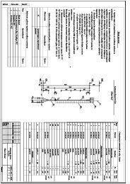
7. ALIGNMENT PROCEDUREThe UHF/VHF Transceivers have broadband tuning range, UHF (450-490 MHz) and VHF (148-174 MHz) should require no special alignment, unless repairs are performed on the transceiverportion. Should repairs be necessary, use the "Test Equipment Diagram" and the “AlignmentPoints Diagram", in conjunction with the following procedures:• Extender Board (ACC-516) is required in order to separate the Digital and RF PCB’s toallow access to the alignment points. Installation instructions are provided with theExtender Board Assembly.Outpt Audio levelSQ for S-BANDCON407RV5RV6RV4TxVCOSQ for N-BANDLowPowerRV3HighPowerRxVCOTCXO1C208 C308RV1RV2TP1DeviationRF BOARDfrequencyBalenceRV402Tone DeviationRef. level forModemRV401RV403DIGITAL BOARDSW401Figure 7.1. Alignment Points Diagram40
7.1. RECEIVERRX VCORX VCO is pre-tuned at the factory and adjustment should not be requiredTo identify existence of defect of RX VCO, check the VCO Control voltage.1. Set the unit to the highest receive frequency, 490MHz(UHF2), 174MHz(VHF) and verifythe VCO control voltage is under 10.0 Volts. If it’s over 10.0 Volts, adjust C308 of RXVCO to 10.0 Volts2. Set the unit to the lowest receive frequency 450MHz(UHF2), 148(VHF) and verify thatthe VCO voltage is above 2.0 Volts. Adjust C308 to 2.0 Volts.※ Note: Use TP1 to measure the voltage.AUDIO OUTPUT LEVEL Adjustment1. Select a receiver channel that is programmed for Standard band (25kHz) operation.2. Prepare standard test signal as follows.a. Set the RF signal generator to the receiver frequency.b. And then set the AF modulation signal to 1 kHz at 3kH deviation.c. Adjust the RF output level of the RF signal generator to –47dBm.3. Apply a standard test signal to the receiver antenna terminals.4. Adjust RV401 for the specific audio output level.LEVEL SHIFTER for Modem option Board (ACC-513, ACC-514)1. Select a receiver channel which is programmed for Standard band (25kHz) operation.2. After Preparing standard test signal for Standard band, apply that signal to the antennaterminals of receiver.3. Adjust RV403 until the center voltage of demodulated signal (1KHz sine wave) of TP401 is2.5 Volts.4. Select a receiver channel which is programmed for Narrow band (12.5kHz) operation.5. After Preparing standard test signal for Narrow band (only decrease deviation of AFmodulation signal as 1.5K from standard test signal for Standard band), apply that signal tothe antenna terminals of receiver.6. Verify the center voltage of demodulated signal of TP401 is 2.5 Volts. If different, AdjustRV403 until the center voltage is near 2.5 Volts for each band (25KHz / 12.5KHz).41
7.2. TRANSMITTERConnect the unit to a Service Monitor with the power meter set to the 10 W scale (or autorange)TCXOSet the channel selector to the mid-range frequency 470 MHz, adjust TCXO1 for a reading of470MHz ±200Hz (155 MHz VHF models).TX VCOTX VCO is pre-tuned at the factory and no more adjustment is requiredTo identify existence of defect of TX VCO, check the VCO Control voltage.1. Set the unit to the highest transmit frequency, 490MHz(UHF2), 174MHz(VHF) key thetransmitter and verify the VCO control voltage is under 10.0 Volts. If it’s over 10.0 Volts,adjust C208 of TX VCO to 10.0 Volts.2. Set the unit to the lowest transmit frequency 450 MHz(UHF2), 148(VHF) key thetransmitter and verify that the VCO voltage is above 1.8 Volts. Adjust C208 to1.8 Volts.※ Note: use TP1 to measure the voltage.CTCSS, DCS & TX Deviation and Balance Adjustment1. a. Set the unit to a mid-frequency range and a CTCSS of 67Hz. Activate PTT and adjustRV402 for desired CTCSS tone deviation.b. Switch to a channel with the same frequency and CTCSS of 250.3Hz. Activate PTT andadjust RV1 to desired CTCSS tone deviation, same as above step.c. Switch between the 67Hz channel and the 250.3Hz channel and adjust RV1 until thedeviation is the same on both channels. It may be necessary to readjust RV402 to get thedesired deviation.2. Set the unit to a mid-frequency and input the TX data with 400 Hz standard audio level.3. Increase the signal level to 20 dB from standard level.4. Monitor the demodulated signal from service monitor. Adjust RV1 to make the monitoredsignal to be a balanced square wave.5. Reduce input signal to the standard level and adjust RV2 for the standard deviation.42
APCThis is the most critical point of the transmitter alignment procedures because ACC-516 (PCB Extender Board) has a voltage drop in transmission mode and so power dropoccurs. That’s the reason why radio outputs higher power than assigned after assembly.To prevent over-power output, follow below procedureIn case alignment for <strong>SD</strong>-<strong>160</strong> series:1. Adjust RV4 and set the power at the point of 1.6W.2. Assemble the radio and then check again RF transmission power is near 2.0W.※ Required alignment point for each radio and proper RF power output when radio isassembled1 Adjust RV4 for High Power (2W, <strong>SD</strong>-161, <strong>SD</strong>-164), (5W, <strong>SD</strong>-171, <strong>SD</strong>-174)2 Adjust RV3 for Low Power (1W) (<strong>SD</strong>-171, <strong>SD</strong>-174 only)7.3. SQUELCH ADJUSTMENTBefore squelch adjustment a SQ type should be selected. Squelch level to open or close (unmuteor mute) is set up by not only software control but also hardware control and programmedby the system option of the ACC-916 programming software.SQUELCH Adjustment (Noise SQ only)1. Select a receiver channel which is programmed for narrow band (12.5kHz) operation.2. Set the RF signal generator to the receiver frequency.Set the AF modulation signal to 1 kHz at 1.5kH deviation.3. Adjust the RF output level of the RF signal generator until the 1kHz signal is heard.4. Adjust the RF signal to the desired level for squelch sensitivity as you monitor SINAD.This is usually 8 to 12 dB sinad.5. On the RF board, adjust RV5 until the squelch is just un-muted (open).6. Switch off the RF generator (squelch should be closed).7. Switch on the RF generator, Squelch should be opened at the SINAD point where RV5 wasadjusted.8. Select a receiver channel that is programmed for wide band operation (25kHz).9. Set the RF signal generator to the receiver frequency.Set the AF modulation signal to 1 kHz at 3kH deviation.10. Adjust the RF output level of the RF signal generator until the 1kHz signal is heard.43
11. Adjust the RF signal to the desired level for squelch sensitivity as you monitor SINAD.This is usually 8 to 12 dB SINAD.12. On the RF board, adjust RV6 until the squelch is just un-muted (open).13. Switch off the RF generator (squelch should be closed).14. Switch on the RF generator, Squelch should be opened at the SINAD point where RV6 wasadjusted.15. Disconnect the test equipment.SQUELCH Adjustment (RSSI SQ only) using ACC-2016 & ACC-916Default setting of squelch level for all radios are approximately set at:1. Squelch open (un-mute) at -114 to -113dBm (0.45 - 0.5mV of the RX signal strength)2. Squelch close (mute) at -117 to -116dBm (0.3 - 0.35mV of the RX signal strength)Changing the default squelch settings requires use of the programming cable and software.Those are designed for use not only as part of the programming kit but also as a tool of squelchlevel setting.The minimum equipment required for squelch level setting is an RF signal generator. <strong>Radio</strong>communication test equipment is recommended.1. Connect DB-9 and DB-15 connector of ACC-2016 to the PC and radio.2. Hook up the power socket of the radio to the power connector of the programming cable, andits antenna connector to the RF input port of the RF signal generator.3. Execute ACC-916 and then select calibration mode.4. Power up the ACC-2016 by plugging power plug to the power supply.(use the DC supply of 9 - 12 Volts 200mA).5. Select “Custom Define” menu of Squelch program menu of ACC-916.6. Adjust the RF signal generator for the desired signal strength to OPEN squelch(e.g. default setting is -113dBm, that is equivalent to 0.5mV)6. Press “Set(OPEN)” button, LED indicator will flash 3 times then it will be ON.7. Adjust the RF signal generator for the desired signal strength to CLOSE squelch(e.g. default setting is -116dBm, that is equivalent to 0.35mV)8. Press “Set(CLOSE)” button, LED indicator will flash 2 times then it will be OFF.9. Press “SAVE” button, LED indicator will flash once.10. Squelch level is now set. Test for the desired level by increasing or decreasing the RFsignal to levels set for open and close squelch (mute LED will be OFF & un-mute LED will be44
ON).※ NOTE: The difference of RF signal strength between the un-mute and mute levels must begreater than or at least equal to 0.15mV (i.e. at least -123.5dBm) for the squelch setting to workproperly. If they are too close, RSSI through the A/D conversion can not differentiate betweenthe mute and un-mute level properly. As a result, it would cause the CD (Carrier Detect) to actintermittently.7.4. TEST EQUIPMENT SETUPModulationMeterDB9-Modular cable15 - 15 ConnectorWATT Meter& 20dB ATT.Audio OutputACC-2<strong>160</strong>(Test Fixture)Audio OutputPower SupplyOscilloscope<strong>Data</strong> Output<strong>Data</strong> /Audio InPTTOnOffInput Monitorsel.PowermaxonSpectrumAnalyzerAudio generatorFrequencyCounter450.025000Figure 7.2. Test equipment setup for transmitter45
DB9-Modular cable15 - 15 ConnectorS.S.GOscilloscopeACC-2<strong>160</strong>(Test Fixture)Audio OutputPower SupplyDistortion Meter<strong>Data</strong> Output<strong>Data</strong> /Audio InPTTOnOffInput Monitorsel.PowermaxonSINAD MeterFigure 7.3. Test equipment setup for ReceiverStandard test conditions are following0 Standard test voltage : 12Vdc1 Temperature for normal test : 25℃±10℃2 Standard audio frequency of S.S.G : 1KHz3 Standard deviation : ±1.5KHz (N-Band), ±3KHz (S-Band)4 Channel Spacing : 12.5KHz (N-Band), 25KHz (S-Band)5 Standard signal input level : -47dBm6 Antenna Impedance : 50 Ohm7 Audio Output Load : 8 Ohm (Ext.)46
8. INTERFACING8.1. External connectionsConnection is made to the <strong>SD</strong>-<strong>160</strong> via an external 50 ohm BNC socket (RF signal) and a highdensity 15-way “D”-type socket (DB-15 connector; control and data signals) with 4-40 UNCthreaded jack posts for more permanent connection. Besides, SCN-12 type circular connector isadded to separate power line from data and analog signals of DB-15 connector.8.2. DB-15 PIN descriptions with input/output levelD-TypePin No.Function Description Signal Type Input/Output1 <strong>Data</strong> modulation IN Signal is directly injected to MOD through Analog signalI/P(Tx Mod)data low pass filter without pre-emphasis. 1KHz audio at 60%peak system deviationinput level =100 to 120mVrms2 <strong>Data</strong> unfiltered OUT(RX disc)O/P3 PTT In(Tx Key)Discriminator audio from the <strong>SD</strong>-<strong>160</strong>. This isthe unprocessed AF signal prior to tonefiltering and de-emphasis.Signal from the ‘external device’ to key the<strong>SD</strong>-<strong>160</strong> transmitter.This line has an internal pull up resistor to+5V. Pulling the line to 0V turns on thetransmitter.Note : If you installed option modemboard, you can select RS-232 signal levelby Jumper (CON407) on the digital board.See Figure 8.2.Analog signal1KHz audio at 60%peak system deviationproduces200 to 300mVrmsTTL level0V = Txo/c = RxRS-232 level (option)+12V = Tx-12V = Rx4 Ground Ground connection to chassis of the radio. 0V (Chassis)5 Serial <strong>Data</strong> Out Serial data output for radio control or TTL level(TXD)program.6 Busy(CD)7 Microphone filteredaudio INIt uses asynchronous data format.Logic level output from <strong>SD</strong>-<strong>160</strong> to indicatewhether a carrier is present or notNote : If you installed an option modemboard, you can select RS-232 signal levelby Jumper (CON407) on the digital board.See Figure 8.2.This signal is injected to the MOD at the pointthrough audio-amplification, pre-emphasisand high pass filtering where sub-audio toneis mixed with audio.TTL level0V = carrier5V = no carrierRS-232 level (option)+12V = carrier-12V = no carrierAudio1KHz audio at 60%peak system deviationinput level =6 to 8VrmsI/PO/PO/PI/P47
8 Serial data IN(RXD)9 Speaker filteredOUT10 Serial data IN foroption modem11 Serial data Out foroption modem12 Serial data busy foroption modem(reserved)Serial command or data input for radiocontrol or program. It uses asynchronousdata format.Audio output from the audio amplifier.It’s filtered by tone-filter, de-emphasis circuit.The Serial data to be transmitted is input tothis pin. It’s only available when optionmodem board is installed. Inputted data aremodulated by modem IC and then injected toMOD.It uses asynchronous data format.The recovered asynchronous serial dataoutput from the receiver. It’s only availablewhen option modem board is installed. Ituses asynchronous data format.To eliminate data loss according to bufferoverrun of slave MCU’s memory, it indicatesbuffer status.13 GPS data input <strong>Data</strong> input for initial setting of GPS module.It follows NMEA 0183 format and usesasynchronous data format.14 DGPS data input <strong>Data</strong> input for DGPS Correction of GPSmodule. It follows NMEA 0183 format anduses asynchronous data format.15 GPS data output Position data output from the GPS module. Itfollows NMEA 0183 format and usesasynchronous data format.TTL levelAudio1KHz audio at 60%peak system deviationproduces Nominal1Vrms @ 8ΩRS-232 levelRS-232 levelRS-232 levelTTL levelTTL levelTTL levelI/PO/PI/PO/PO/PI/PI/PO/PTable 8.1. Pin description of DB-15 ConnectorDB-15 CONNECTORBUSY6DATA MOD IN 1MIC IN (AF)7<strong>Data</strong> OUT (AF)2SERIAL IN (PROG.) 8PTT IN3SPK OUT9GND4SERIAL DATA IN (OPT) 10SERIAL OUT (PROG.) 51112131415SERIAL DATA OUT (OPT)SERIAL BUSY OUT (OPT)GPS DATA IN (OPT)DGPS DATA IN (OPT)GPS DATA OUT (OPT)Figure 8.1. Pin-outs of DB-15 connector48
8.3. Internal componentsCON407CON40712RV402RV401RV403(Default)Available signal level for PTT & Busy= TTL level5DigitalBoardSW4016(RTS mode only)Available signal level for PTT & Busy= RS-232 levelFigure 8.2. Signal level selector for PTT(RTS) & BusyCHANNEL NO.12 3 4SWITCH POSITION1 2 3 4 1 2 3 4 1 2 3 4 1 2 3 45 6 7 81 2 3 4 1 2 3 4 1 2 3 4 1 2 3 49 10 11 121 2 3 4 1 2 3 4 1 2 3 4 1 2 3 4131415161 2 3 4 1 2 3 4 1 2 3 4 1 2 3 4SW401Figure 8.3. Setting of channel selector switch for each channel49
8.4. Option board pin-out chart8.4.1. ACC-513 (GMSK Modem Option board)ConnectorNo.Connector 1Connector 2PinInput/FunctionDescriptionNo.Output1 VCC 6V to 12V Power Input I/P2 GND Ground3 PTT Signal from the digital board to enable transmitter circuit ofmodem board.I/P4 TXD_EN It ensures that the radio has stabilized in transmissionbefore the data is processed for modulation.I/P5 TX_END To finish transmission, it indicates memory buffer of MasterMCU of digital board is empty.O/P6 MUTELogic level input from digital board to indicate whether a(Busy)carrier is present or notI/P7 MODEM_EN Modem Enable input I/P8 POWER_SAVE Power save input for modem board. I/P9 CMD_EN It indicates that command for Modem programming iseffective.I/P10 CMD_IN/OUT <strong>Data</strong> Input and Output for Modem programming. I/P,O/P11 CMD_CLK Clock Input for Modem programming. I/P12 MODEM_SEL It Indicates modem type to Master MCU for programming. O/P13 RX_IN The GMSK signal input for the receiver of modem IC. I/P14 TX_OUT The GMSK filtered Tx output signal. O/P1 Serial_IN The Serial data to be transmitted is input to this pin. I/P2Serial_OUTThe recovered asynchronous serial data output from thereceiver.O/P3BusyTo eliminate data loss according to buffer overrun of slaveMCU’s memory, it indicates buffer status.O/P4Carrier_Detect Handshake signal for RTS control mode. It indicateswhether Slave MCU of modem has decoded data or not.O/P5PTT_INHandshake signal for RTS control mode. It requests datatransmission to Slave MCU of modem.I/P6 PROGRAM It’s reserved input for firmware upgrade. I/PTable 8.2. Pin description of DB-15 Connector8.4.2. ACC-514 (FFSK Modem Option board)ConnectorNo.Connector 1PinInput/FunctionDescriptionNo.Output1 VCC 6V to 12V Power Input I/P2 GND Ground3 PTT Signal from the digital board to transmit data key the <strong>SD</strong>-<strong>160</strong> transmitterI/P4 TXD_EN It ensures that the radio has stabilized in transmissionbefore the data is processed for modulation.I/P50
5 TX_END To finish transmission, it indicates memory buffer of MasterMCU of digital board is empty.O/P6 MUTELogic level input from digital board to indicate whether a(Busy)carrier is present or notI/P7 MODEM_EN Modem Enable input I/P8 POWER_SAVE Power save input for modem board. I/P9 CMD_EN It indicates that command for Modem programming iseffective.I/P10 CMD_IN/OUT <strong>Data</strong> Input and Output for Modem programming. I/P,O/P11 CMD_CLK Clock Input for Modem programming. I/P12 MODEM_SEL It Indicates modem type to Master MCU for programming. O/P13 RX_IN The FFSK/MSK signal input for the receiver of modem IC. I/P14 TX_OUT The FFSK/MSK signal output when the transmitter isenabled.O/PConnector 21 Serial_IN The Serial data to be transmitted is input to this pin. I/P2Serial_OUTThe recovered asynchronous serial data output from thereceiver.O/P3BusyTo eliminate data loss according to buffer overrun of slaveMCU’s memory, it indicates buffer status.O/P4Carrier_Detect Handshake signal for RTS control mode. It indicateswhether Slave MCU of modem has decoded data or not.O/P5PTT_INHandshake signal for RTS control mode. It requests datatransmission to Slave MCU of modem.I/P6 PROGRAM It’s reserved input for firmware upgrade. I/PTable 8.3. Pin description of DB-15 Connector8.4.3. ACC-515 (GPS Option board)PinInput/FunctionDescriptionNo.Output1 VCC 6V to 12V Power Input I/P2 VBAT Backup Power Input (3.3V) I/P3 ENABLE GPS <strong>Data</strong> Out Enable I/P4 PSAVE GPS Power Enable (& Power save input for GPS) I/P5 GND Ground6 GPS_OUT Position <strong>Data</strong> Output O/P7 DGPS_IN DGPS Correction <strong>Data</strong> Input I/P8 GPS_IN Initial Setting <strong>Data</strong> Input I/P9 +5V 5V Power Input I/PTable 8.4. Pin description of DB-15 Connector51
8.5. Wiring DiagramCON401PIN# DESCRIPTION1 DATA MOD IN2 DATA OUT(AF)3 PTT IN4 GND5 SERIAL OUT (PROG.)6 BUSY7 MIC IN(AF)8 SERIAL IN (PROG.)9 SPK OUT10 SERIAL DATA IN (OPT)11 SERIAL DATA OUT (OPT)12 SERIAL BUSY OUT (OPT)13 GPS DATA IN (OPT)14 DGPS DATA IN (OPT)15 GPS DATA OUT (OPT)CON404CON403PIN# DESCRIPTION PIN# DESCRIPTION1 SERIAL_IN 1 VCC2 SERIAL_OUT 2 GND3 BUSY 3 PTT4 Carrier_Detect 4 TXD_EN5 PTT_IN 5 TX_END6 PROGRAM 6 MUTE (BUSY)7 MODEM_EN8 POWER_SAVE9 CMD_EN10 CMD_IN/OUT11 CMD_CLK12 MODEM_SEL13 RX_IN14 TX_OUTCON401CON407RV5RV6CON4069CON404RV401RV4RV3TCXO1CON1511 2 2 1RV402CON406PIN# DESCRIPTION1 VCC2 VBAT3 ENABLE4 PSAVE5 GND6 GPS_OUT7 DGPS_IN8 GPS_IN9 +5VRV403CON403SW401C208C308RV1CON405RV21817TP1RF BOARDCON405PIN# DESCRIPTION1 VCC2 GND3 PLL_DATA4 PLL_LOCK5 PLL_EN6 PLL_CLK7 MOD_IN8 CH_BW9 PWR_SEL10 AUDIO11 TX_EN12 PA_EN13 RX_EN14 RSSI15 +5V16 VCC17 BUSY18 GNDDIGITAL BOARD52
9. TROUBLE SHOOTING GUIDEThis chapter contains 6 troubleshooting tables for the following <strong>SD</strong>-<strong>160</strong> components:• Receiver• Transmitter• Synthesizer• RX VCO (Voltage Controlled Oscillator)• TX VCO (Voltage Controlled Oscillator)• Control circuit53
STARTVERY LOWORNO 12DB SINADNOISE ATSPKR WHEN RADIOIS UNSQ'D?NONOISE ATPIN 9 OFIFIC IC6?NOCHECK IFICIC6YESYESINJECT A45.1MHzSIGNAL AT C71CHECK AFICIC412IS 12DBSINAD NEAR-103DBM?NOIS 2ND LOON FREQ?NOIS PIN 1OF IFIC AT4.4V DC?NOCHECK IFICYESYESYESINJECT A45.1MHzSIGNAL AT C70CHECK IF AMP ANDPERIPHERALCOMPONENTSCHECK VDCOF ALL PINS OFIFIC IC6CHECK 2ND LOXTAL ANDCOMPONENTSNOIS 12DBSINAD NEAR-115DBM?IS Q16BIASEDCOREECTLY?AREVOLTAGESON PINS OK?NOCHECK EXTERNALCOMPONENTSCONNECTED TO IFIC.IF OK REPLACE IC6YESYESYESINJECTON CH SIGNALAT C62CHECK XTALFILTERSXF1 & XF2CHECK EXTERNALCOMPONENTSCONNECTED TO IFICIS 12DBSINAD NEAR-113DBM?NOIS 1ST LO ATPIN 4 OF T2NEAR 3DBM?NOCHECK VCOSYNTHYESYESINJECTON CH SIGNALAT C601BAD MIXERCIRCUITRY(D6, T1, T2)IS 12DBSINAD NEAR-119DBM?NOIS Q601BIASEDCORRECTLY?NOCHECK RX5V (Q2) ANDBIAS COMPONENTS(R64, R601, R602, L605)YESYESCHECK HARMONICFILTER ANDANTENNA PATHCHECK FRONT ENDFILTERS FOR OPENSOR SHORTSFigure 9.1. Troubleshooting Flow Chart for Receiver54
NO POWER OUTPUTAT ANTENNACHECK RF OUTPUTPOWER AT C34HIGH B+CURRENTB+CURRENTDRAW?( < 0.1A )NO OR LOW B+CURRENTCHECK B+ ONFINAL STAGESNO1) CHECK FOR INCORRECTOR DAMAGED PARTS INFINAL STAGES.2) VERIFY B+ FEED CIRCUITINTEGRITY(I.E. CONDITIONAL SHORTS)OUTPUTPOWERLEVELGOOD?YESYE<strong>SD</strong>C-DC OUTPUT1) <strong>SD</strong>-161 : 5.5V2) <strong>SD</strong>-164 : 6.5V3) <strong>SD</strong>-171 : 7.5V4) <strong>SD</strong>-174 : 7.5VB+ IS WITHIN+/- 0.5V OFDC-DC OUT?NO1) CHECK FOR INCORRECTOR DAMAGED PARTS INFINAL STAGES.2) VERIFY B+ FEED CIRCUITINTEGRITY(I.E. CONDITIONAL OPENS.)1) CHECK PIN DIODES(D3, D5)& TX_B2 VOLTAGE.2) VERIFY CORRECT COMPONENTSIN HARMONIC FILTER.IS Q703BIASEDPROPERLY?NOCHECK BIAS CIRCUITRYIF OKCHECK CONTORLVOLTAGE(COLLECTOR OF Q11)YESP.A. STAGE(S) BAD:1) VERIFY GAIN FROM INDIVIDUALP.A. STAGES.2) REPLACE LOW/NO GAIN DEVICE(S)YESVERIFY INPUT OF P.A.STAGES(> +10DBM)INPUTOF P.A.STAGESGOOD?NOISCONTROLVOLTAGEHIGH ORLOW?LOWTROUBLESHOOT POWERCONTROL CIRCUIT AND/OR VERIFY POWER SETUSING RV4.(COLLECTOR Q11 > 5.0V)HIGHREPLACEQ703VERIFY VCO OUTPUT(> 0DBM)VCO OUTPUTGOOD?NOTROUBLESHOOTVCOYESBUFFER & DRIVER STAGE BAD:1) VERIFY GAIN FROM EACH BUFFER& DRIVER STAGE2) REPLACE LOW/NO GAIN DEVICE(S)Figure 9.2. Troubleshooting Flow Chart for Transmitter55
STARTVISUALCHECK OFTHE BOARDOK?YESNOCORRECTPROBLEM+5V AT IC2PINS 3 & 4?NOCHECK 5VREGULATORYESIF PIN1(MOD) ANDPIN4(B+) OF TCXO1ARE 1.9VDC AND5.0VDC, RESPECTIVELYTHEN REPLACE TCXONOIS 12.8MHZSIGNAL ATTCXO1 PIN1?NOIS 12.8MHZSIGNAL ATIC2 PIN1?YESYESCHECK R14 &C8ARESIGNALS ATPINS 15 OR 16OF IC2?NODO PINS 9, 10& 11 OF IC2TOGGLE WHENCHANNEL ISCHANGED?NOCHECKPROGRAMMINGLINES BETWEENIC401 AND IC2 PINS9, 10 & 11YESYESIC2 BADNOISTHERE ANYSHORT BETWEENAROUNDCIRCUITRY ANDPIN 15 & 16OF IC2NOAREWAVEFORMSAT PINS 15,16SQUARE?IS INFORMATIONFROM uP IC401CORRECT?NOCHECK uPIC401YESYESYESREMOVESHORTSOPEN R12 ANDTHEN CHECKVOLTAGE ATD903 PIN1IC2 BADIS D903 PIN1>15.0VDC?NOCHECK VOLTAGEDOUBLER(TRIPLER)YES<strong>SD</strong>-161/171 : USE VOLTAGE TRIPLER<strong>SD</strong>-164/174 : USE VOLTAGE DOUBLERIF R98 & C101 AND R13& C5 ARE OK, THENTROUBLESHOOT VCONOIS RF LEVELAT IC2 PIN 8BETWEEN -15& +5DBM?YESAREC1, C2, C3,C4, C18, R9,R10 & R11OK?YESAREEXT. CHARGEPUMP(Q3~Q6)CIRCUITRYOK?YESNONOREPLACE ORRESOLDERNECESSARYCOMPONENTSREPLACE ORRESOLDERNECESSARYCOMPONENTSIC2 BADFigure 9.3. Troubleshooting Flow Chart for Synthesizer56
LOW OR NO POWERAT PIN4 OF T2VISUALCHECK OFTHE BOARDOK?YESNOCORRECTPROBLEMCHECK VOLTAGEREGULATORCIRCUITRY FORRX VCONO4.2VDC ATEMITTER OFQ20?YESARE Q301 &Q302 BIASEDCORRECTLY?NOCHECK R306,R307, R308, R309& L304YESCHECKRESONANT TANK(C307~9 & L303)AND FEEDBACK(C312 & C315)NOIS THERE RFOSCILLATION ATCOLLECTOR OFQ301?YESSET LOWESTFREQUENCYIS CONTROLVOLTAGE(TP1)BETWEEN 1VDCAND 3VDC?NOIS D301DCBIASED?NOIF R302 & L301 ARE OK,MAKE SURESYNTHESIZER ISWORKING CORRECTLYYESYESREPLACE C303NOIS KVCOBETWEEN 6MHZ/VAND 7MHZ/V?CHECKRESONANT TANK(C307~9 & L303)YESIS RF LEVEL ATC318 BETWEEN -3& 0DBM?YESNOIF L305, COUPLING CAP. (C311, 313,318) AND FEEDBACK (C312 & C315,L304, R309) ARE OK, REPLACE LOWGAIN DEVICE(S)CHECK RX_5VAND BUFFERCOMPONENTSNOARE Q19BIASEDCORRECTLY?NOIS RX BUFFERSTAGE WORKINGCORRECTLY?YESYESIF L14 ANDC100 ARE OK,REPLACE Q19REPLACE OR RESOLDERNECESSARY COMPONENTSOF HARMONIC FILTER(C28 ~ 32, L4 ~ 5)Figure 9.4. Troubleshooting Flow Chart for RX VCO57
LOW OR NO POWERAT INPUT TO P.A.RF POWER IS OK BUTNO OR INCORRECTMODULATIONCORRECTPROBLEMNOVISUALCHECK OFTHE BOARDOK?IF NO MOD.,IS 1.9VDC ATR201?NOIS1.9VDC ATR201 FOR NOMOD. IN?NOCHECK REF.VOLTAGEDRIVER (IC4A)YESYESYESCHECK VOLTAGEREGULATORCIRCUITRY FORTX VCONO4.2VDC ATEMITTER OFQ8?IF R26, C19 ARE OKCHECK ALL PARTSAROUND IC3CHECK R206,R207, R208, R209& L204NOYESARE Q201 &Q202 BIASEDCORRECTLY?IS THERE200mVrms SIGNALAT R201 UNDERSTANDARD TESTCONDITION?YESNOIF R26, C19 ARE OKCHECK ALL PARTSAROUND IC3CHECKRESONANT TANK(C207~9 & L203)AND FEEDBACK(C212 & C215)NOYESIS THERE RFOSCILLATION ATCOLLECTOR OFQ201?YESIS THEREDIFFERENT FREQ.DEVIATION FOREACH CH FREQ.?YESTROUBLESHOOTDIGITAL BOARD FORSIGNAL PATHNOREPLACE INCORRECTVALUE FOR C204, 205AND L202SET LOWESTFREQUENCYIS CONTROLVOLTAGE(TP1)BETWEEN 1VDCAND 3VDC?NOIS D201DCBIASED?NOIF R202 & L201 ARE OK,MAKE SURESYNTHESIZER ISWORKING CORRECTLYYESYESREPLACE C203NOIS KVCOBETWEEN 6MHZ/VAND 7MHZ/V?CHECKRESONANT TANK(C207~9 & L203)YESIS RF LEVEL ATC218 BETWEEN -3& 0DBM?YESNOIF L205, COUPLING CAP. (C211, 213,218) AND FEEDBACK (C212 & C215,L204, R209) ARE OK, REPLACE LOWGAIN DEVICE(S)TX BUFFER(Q9) AND/OR DRIVER(Q10)STAGE(S) BAD:1)VERIFY GAIN FROM EACH STAGE.2)REPLACE LOW/NO GAIN DEVICE(S)Figure 9.5. Troubleshooting Flow Chart for TX VCO58
STARTAPPLY POWERTO RADIOWAS POWER_ONINDICATION LIGHTEMITTED?NOIS POWERSUPPLIED TO DC-DC CONVERTER?NOCHECK CONTACT OFPOWER CONNECTOR ANDRUNNERS BETWEENPOWER CONNECTOR & DC-DC CONVERTERYESYESCHECK EEPROM DATAFOR MODEM OPTION &TYPE OF INSTALLEDMODEM(ACC-513 OR ACC514 ?)GREEN LEDFLASH IS THERECONTINUOUS LEDFLASH?YELLOWLED FLASHNOWASNO WARNING LEDINDICATION?YESISCONTACT OF18PIN INTERNALCONNECTORBETWEEN RF ANDDIGITA B'DOK?YESNOREASSEMBLE RF &DIGITAL B'D ANDCHECK AGAIN. BUT, IFHAVE SAME PROBLEMREPLACE CONNECTOR(CON405)CHECKEEPROM DATADONEIS VCC AT CON405PINS 1 & 16 OK?NOTROUBLESHOOTDC-DC CONVERTERIS EEPROM DATANO PROBLEM?YESNOREPROGRAM EEPROM& CHECK AGAINBUT, IF HAVE SAMEPROBLEM REPLACEEEPROM (IC402)YES+5V ATCON405PIN 15?NOTROUBLESHOOT5V REGULATORCIRCUITRY OF RF B'DTROUBLESHOOT FREQUENCYSYNTHESIZER CIRCUITRY(INCLUDES VCO & TCXO)YESWITH POWER SUPPLIED TO RADIO CHECK THEFOLLOWING:1) 5V AT THE PINS 39 & 40 OF IC401. IF NONE,CHECK L401, C465 & C477.IS CORRECTMODEMINSTALLED?NOCHANGE MODEM2) WITH HIGH IMPEDENCE PROBE CHECK FOR8.0MHZ AT PINS 2 & 3 OF IC401. IF NO SIGNALCHECK IC401 / X401 / R456 / C441 / C442.YES3) CHECK DC AT PIN 4 OF IC401. IF < 4.5VDC,CHECK RESET CIRCUITRY(IC414 / R457 / R458 / C443)ISCONTACTBETWEEN MODEMAND DIGITAL B'DOK?YESNOREINSTALL MODEM TODIGITAL B'D ANDCHECK AGAIN. BUT, IFHAVE SAME PROBLEMREPLACE CONNECTOR(CON403)4) CHECK FOR TYPICAL VOLTAGES OF IC401NOISLED CONTROLSIGNAL PRESENTON POWER UP ATIC401 PINS23 & 24?TROUBLESHOOT ORREPLACE MODEMYESCHECK LED401 ANDITS DRIVERS(Q401, Q411)DONEFigure 9.6. Troubleshooting Flow Chart for Control Circuit59
10. VOLTAGE CHARTTRANSISTORS OF CONTROL BOARDREF# DescriptionReceive stateTransmit stateE B C E B CQ401 KRA104S 5.0 4.6 0.0 5.0 4.6 0.0Q402 KRA104S 1.9 4.9 1.8 1.9 4.9 1.9Q403 KRC104S 0.0 4.9 0.0 0.0 0.0 5.0Q406 KRC104S 0.0 4.9 0.0 0.0 0.0 5.0Q407 KTA1504SY 6.5 6.4 3.3 6.5 5.9 6.5Q408 KRC104S 0.0 0.0 5.9 0.0 5.0 0.0Q410 KRC104S 2.1 4.9 5.2 0.0 0.0 6.5Q411 KRC104S 1.9 4.9 5.1 1.9 5.0 5.1Q413 KRA104S 5.0 4.6 0.1 5.0 0.6 4.9Q417 KTA1504SY 0.0 4.9 0.0 0.0 5.0 0.0Q418 KRC104S 0.0 0.0 4.8 0.0 5.0 0.0Q419 KRC110S 0.0 0.0 0.0 0.0 0.0 0.0Q424 KRA104S 6.5 6.5 0.0 6.5 6.5 0.0Q425 KRC104S 0.0 0.0 6.5 0.0 0.0 6.5TRANSISTORS OF RF BOARDREF# DescriptionReceive stateTransmit stateE B C E B CQ1 KRA110S 5.0 4.8 0 5.0 0 4.8Q2 KRA110S 5.0 0.0 4.8 5.0 4.8 0Q3 KTC4075 2.4 2.0 15.0 2.4 2.0 15.0Q4 KTC4075 0.0 0.0 1.8 0 0 2.0Q5 KTA2014 0.0 2.4 0 0 2.4 0Q6 KTA2014 15.0 15.0 1.8 15.0 15.0 2.0Q7 KRA104S 5.0 4.8 0.4 5.0 4.8 0.4Q8 KTC3875S 0.0 0.0 0 4.2 4.8 4.9Q9 BFR92A 0.0 0.0 0 1.4 2.1 4.9Q10 PBR951 0.0 0.0 0 0 0.7 3.5Q11 KTA1663 6.5 6.5 0 6.5 5.8 3.7Q12 KTC3875S 0.0 0.0 6.5 0.4 1.0 5.6Q14 KRC104S 0.0 0.0 0 0 4.1 0Q15 KTC3875S 0.2 0.9 6.5 1.0 1.6 6.4Q16 BFR92A 0.0 0.7 4.1 0 0 0Q17 KRC104S 0.0 4.9 0 0 4.9 0Q18 KRC104S 0.0 4.9 0 0 4.9 0Q19 BFR92A 1.4 2.1 4.9 0 0 0Q20 KTC3875S 4.1 4.7 4.8 0 0 0Q21 KRC104S 0.0 4.9 0 0 4.9 0Q22 KRA104S 4.4 0.0 4.4 0 0 0Q24 KRC104S 0.0 0.0 4.6 0 0 060
ICS OF RF BOARDRECEIVE MODEPIN #IC1 IC2 IC3 IC4 IC5 IC6TK71750SCL MB15A02PFV1 NJM12904V NJM12904V NJM12904V TA31136FN1 6.5 2.0 (OSC1) 1.9 1.9 0.9 4.3(OSC1)2 0.0 2.0 (OSC2) 1.9 1.9 2.6 3.7(OSC2)3 6.5 5.0 1.8 1.9 2.6 3.14 1.2 5.0 0.0 0.0 0.0 4.45 5.0 0.0 1.9 ANALOG 0.0 4.06 - 0.0 N/C ANALOG 0.2 3.97 - 5.0 N/C ANALOG 0.0 0.78 - 2.6 (RF) 5.0 5.0 5.0 0.79 - 0.0 - - - 1.0(AF)10 - 0.0 - - - 4.411 - 0.0 - - - 3.512 - 4.8 - - - ANALOG13 - 0.0 - - - 0.014 - 0.0 - - - 0.015 - 2.1 - - - 0.016 - 0.0 - - - 1.0(IF)ICS OF RF BOARDTRANSMIT MODEPIN #IC1 IC2 IC3 IC4 IC5 IC6 (OFF)TK71750SCL MB15A02PFV1 NJM12904V NJM12904V NJM12904V TA31136FN1 6.5 2.0 (OSC1) 1.9 1.9 1.7 -2 0.0 2.0 (OSC2) 1.9 1.9 2.6 -3 6.5 5.0 1.9 1.9 2.6 -4 1.2 5.0 0.0 0.0 0.0 -5 5.0 0.0 1.9 0 0.8 -6 - 0.0 N/C 0 0.8 -7 - 5.0 N/C 0 0.9 -8 - 2.6 (RF) 5.0 5.0 5.0 -9 - 0.0 - - -10 - 0.0 - - -11 - 0.0 - - -12 - 4.8 - - -13 - 0.0 - - -14 - 0.0 - - -15 - 2.1 - - -16 - 0.0 - - -61
ICS OF DIGITAL BOARDRECEIVE MODEPIN IC402 IC403 IC404(off) IC405 IC406 IC407 IC408 IC409# CSI24WC04 NJM12903V KIA324F KIA324F MC14066B MC14066B KIA324F MC14053B1 0.0 0.2 0.0(Analog) 0.0(Analog) 1.9(Analog) 0.0(Analog) 1.9(Analog) 0.52 0.0 0.1 0.0(Analog) 0.0(Analog) 1.9(Analog) 1.8(Analog) 1.9(Analog) 2.7(Analog)3 0.0 0.1 1.7(Analog) 1.7(Analog) 0.0(Analog) 1.8(Analog) 1.6(Analog) 0.04 0.0 0.0 0.0 0.0 0.0(Analog) 1.5(Analog) 4.9 1.1(Analog)5 5.0 1.9 1.7(Analog) 0.0(Analog) 0.0(S/W2) 0.0(S/W2) 1.6(Analog) 1.1(Analog)6 5.0 1.8(Analog) 0.0(Analog) 0.0(Analog) 0.0(S/W3) 0.0(S/W3) 1.9(Analog) 0.07 N/C 4.9Vp-p 0.0(Analog) 0.0(Analog) 0.0 0.0 1.9(Analog) 0.08 5.0 4.9 0.0(Analog) 0.0(Analog) 0.0(Analog) 1.9(Analog) 1.9(Analog) 0.09 - - 0.0(Analog) 0.0(Analog) 0.0(Analog) 1.7(Analog) 1.9(Analog) 0.110 - - 1.7(Analog) 0.0(Analog) 1.0(Analog) 1.8(Analog) 1.5(Analog) 0.111 - - 0.0 0.0 1.0(Analog) 0.0(Analog) 0.0 5.012 - - 1.7(Analog) 0.0(Analog) 4.9(S/W4) 0.0(S/W4) 1.4(Analog) 0.013 - - 0.0(Analog) 0.0(Analog) 4.9(S/W1) 0.0(S/W1) 1.9(Analog) 1.814 - - 0.0(Analog) 0.0(Analog) 5.0 5.0 1.9(Analog) 1.815 - - - - - - - 2.7(Analog)16 - - - - - - - 5.0ICS OF DIGITAL BOARDRECEIVE MODEPIN IC410 IC411 IC412 IC414 IC416 IC417 IC418# MSNBLPS KIA324F LM386 KIA7042F KIA324F KIA324F TC7S66FU1 1.9 1.9(Analog) 1.3 5.0 1.9(Analog) N/C 1.9(Analog)2 0.0 1.9(Analog) 0.0 0.0 1.9(Analog) N/C 1.9(Analog)3 1.9 1.9(Analog) 0.0(Analog) 5.0 1.7Analog) N/C 0.04 1.9 4.9 0.0 - 4.9 4.9 4.85 1.9 1.9 Audio - 1.7(Analog) 1.3(Analog) 5.06 5.0 1.9(Analog) 6.5 - 1.9(Analog) 1.9(Analog) -7 1.9 2.7(Analog) 3.3 - 1.9(Analog) 1.9(Analog) -8 2.7(Analog) 1.9 1.3 - 2.5(Analog) 1.0(Analog) -9 CLK 1.9 - - 1.5(Analog) 1.0(Analog) -10 0.0 1.9 - - 1.5(Analog) 1.0(Analog) -11 /CLK 0.0 - - 0.0 0.0 -12 0.0 1.9 - - 1.0(Analog) N/C -13 1.9 1.9(Analog) - - 1.0(Analog) N/C -14 1.9 1.9(Analog) - - 1.0(Analog) N/C -15 - - - - - - -16 - - - - - - -62
ICS OF DIGITAL BOARDTRANSMIT MODEPIN IC402 IC403 IC404 IC405 IC406 IC407 IC408 IC409# CSI24WC04 NJM12903V KIA324F KIA324F MC14066B MC14066B KIA324F MC14053B1 0.0 0.2 1.9(Analog) 1.9(Analog) 1.9(Analog) 1.9(Analog) 1.9(Analog) 0.42 0.0 0.1 1.9(Analog) 1.9(Analog) 0.0(Analog) 1.9(Analog) 1.9(Analog) 3.0(Analog)3 0.0 0.1 1.7(Analog) 1.7(Analog) 0.0(Analog) 1.9(Analog) 1.6(Analog) 0.04 0.0 0.0 4.9 4.9 0.0(Analog) 1.7(Analog) 4.9 0.0(Analog)5 5.0 1.9 1.7(Analog) 1.9(Analog) 5.0(S/W2) 0.0(S/W2) 1.5(Analog) 0.7(Analog)6 5.0 1.7(Analog) 1.9(Analog) 1.9(Analog) 0.0(S/W3) 0.0(S/W3) 1.9(Analog) 0.07 N/C 0.0 1.9(Analog) 1.9(Analog) 0.0 0.0 1.9(Analog) 0.08 5.0 5.0 1.9(Analog) 1.9(Analog) 0.0(Analog) 1.9(Analog) 1.9(Analog) 0.09 - - 1.9(Analog) 1.9(Analog) 1.9(Analog) 1.7(Analog) 1.9(Analog) 5.010 - - 1.7(Analog) 1.9(Analog) 0.7(Analog) 1.9(Analog) 1.5(Analog) 5.011 - - 0.0 0.0 0.0(Analog) 0.0(Analog) 0.0 0.012 - - 1.7(Analog) 1.9(Analog) 0.0(S/W4) 0.0(S/W4) 1.4(Analog) 1.813 - - 1.9(Analog) 1.9(Analog) 0.0(S/W1) 5.0(S/W1) 1.9(Analog) 2.114 - - 1.9(Analog) 1.9(Analog) 5.0 5.0 1.9(Analog) 1.815 - - - - - - - 0.4(Analog)16 - - - - - - - 5.0ICS OF DIGITAL BOARDTRANSMIT MODEPIN IC410 IC411 IC412 IC414 IC416 IC417 IC418# MSNBLPS KIA324F LM386 KIA7042F KIA324F KIA324F TC7S66FU1 1.9 1.9(Analog) 1.3 5.0 1.9(Analog) N/C 1.9(Analog)2 0.0 1.9(Analog) 0.0 0.0 1.9(Analog) N/C 1.9(Analog)3 2.2 1.9(Analog) 0.0(Analog) 5.0 1.7Analog) N/C 0.04 1.9 4.9 0.0 - 4.9 4.9 4.85 1.9 1.9 1.3 - 1.7(Analog) 1.3(Analog) 5.06 5.0 1.9(Analog) 6.5 - 1.9(Analog) 1.9(Analog) -7 1.9 3.0(Analog) 6.5 - 1.9(Analog) 1.9(Analog) -8 0.4(Analog) 1.9 1.3 - 0.6(Analog) 3.6(Analog) -9 CLK 1.9 - - 2.7(Analog) 3.6(Analog) -10 0.0 1.9 - - 1.5(Analog) 0.0(Analog) -11 /CLK 0.0 - - 0.0 0.0 -12 0.0 1.9 - - 0.7(Analog) N/C -13 1.9 1.9(Analog) - - 0.7(Analog) N/C -14 1.9 1.9(Analog) - - 0.7(Analog) N/C -15 - - - - - - -16 - - - - - - -63
MCU (IC401)RECEIVE MODEPIN # Voltage PIN # Voltage PIN # Voltage PIN # Voltage1 0.0 21 0.0 41 4.7 61 4.92 1.7(XOUT) 22 5.0 42 4.7 62 0.03 1.7(XIN) 23 5.0 43 N/C 63 0.04 5.0 24 5.0 44 0.0 64 0.05 N/C 25 N/C 45 5.0 65 0.06 0.4 26 N/C 46 0.0 66 4.97 0.0 27 5.0 47 0.0 67 0.08 N/C 28 N/C 48 0.0 68 0.09 0.0 29 N/C 49 5.0 69 0.010 0.0 30 2.1(Analog) 50 N/C 70 4.911 5.0 31 RSSI(Analog) 51 N/C 71 3.412 5.0 32 N/C 52 N/C 72 0.013 4.7 33 0.0 53 4.7 73 N/C14 0.0 34 0.0 54 N/C 74 N/C15 0.0 35 0.0 55 N/C 75 N/C16 N/C 36 5.0 56 0.0 76 0.017 N/C 37 0.0 57 4.8 77 0.018 4.9Vp-p 38 0.0 58 4.8 78 0.019 4.9Vp-p 39 5.0 59 4.8 79 4.920 N/C 40 5.0 60 4.8 80 N/CMCU (IC401)TRANSMIT MODEPIN # Voltage PIN # Voltage PIN # Voltage PIN # Voltage1 0.0 21 0.0 41 4.8 61 4.92 1.7(XOUT) 22 5.0 42 4.8 62 0.03 1.7(XIN) 23 0.0 43 N/C 63 0.04 5.0 24 5.0 44 0.0 64 0.05 N/C 25 N/C 45 5.0 65 0.06 0.4 26 N/C 46 0.0 66 0.07 0.0 27 5.0 47 0.0 67 0.08 N/C 28 N/C 48 5.0 68 5.09 0.0 29 N/C 49 5.0 69 0.010 0.0 30 2.1(Analog) 50 N/C 70 5.011 5.0 31 0(Analog) 51 N/C 71 3.412 5.0 32 N/C 52 N/C 72 0.013 0.0 33 0.0 53 0.5 73 N/C14 0.0 34 0.0 54 N/C 74 N/C15 0.0 35 0.0 55 N/C 75 N/C16 N/C 36 5.0 56 0.0 76 0.017 N/C 37 0.0 57 4.9 77 5.018 4.9Vp-p 38 0.0 58 4.9 78 4.219 0.0 39 5.0 59 4.9 79 0.020 N/C 40 5.0 60 4.9 80 N/C64
11. ELECTRICAL PARTS LIST11.1. PARTS LIST FOR <strong>SD</strong>-161PART NO. NAME & DESCRIPTION REF PART NO. NAME & DESCRIPTION REF180-301-7Z METAL POLY CAP 0.33UF 63V C1 130-443-7 CHIP CERAMIC 0.47UF GRM40 Y5V474Z 16V PT C54180-209-8 METAL POLY CAP 0.022UF 223K 63V BOX C2 134-780-1Y CHIP CERAMIC 470PF GRM36 X7R471K 50V C55180-126-6Z METAL POLY CAP 0.01UF 63V C3 134-780-1Y CHIP CERAMIC 470PF GRM36 X7R471K 50V C56180-126-6Z METAL POLY CAP 0.01UF 63V C4 134-780-1Y CHIP CERAMIC 470PF GRM36 X7R471K 50V C57131-127-7Y CHIP CERAMIC 10PF GRM36 COG100D 50V C5 134-780-1Y CHIP CERAMIC 470PF GRM36 X7R471K 50V C58141-059-2 CHIP TANTALUM 10UF 293D106X06R3A2T6.3V C6 134-780-1Y CHIP CERAMIC 470PF GRM36 X7R471K 50V C59134-780-1Y CHIP CERAMIC 470PF GRM36 X7R471K 50V C7 134-780-1Y CHIP CERAMIC 470PF GRM36 X7R471K 50V C60136-018-7Y CHIP CERAMIC 6PF GRM36 COG060D 50V C8 134-767-0Y CHIP CERAMIC 4.7PF GRM40 COG4R7C 50V PT C61134-780-1Y CHIP CERAMIC 470PF GRM36 X7R471K 50V C9 132-034-1Y CHIP CERAMIC 20PF GRM36 COG200J 50V C62130-B19-8Y CHIP CERAMIC 0.1UF GRM36 Y5V104Z 16V C10 138-245-6Y CHIP CERAMIC 82PF GRM36 COG820J 50V C64130-B16-5Y CHIP CERAMIC 0.01UF GRM36 X7R103K 16V C11 131-851-7Y CHIP CERAMIC 18PF GRM36 COG180J 50V C66131-089-7Y CHIP CERAMIC 1UF GRM40 Y5V105Z 16V PT C12 131-089-7Y CHIP CERAMIC 1UF GRM40 Y5V105Z 16V PT C68134-780-1Y CHIP CERAMIC 470PF GRM36 X7R471K 50V C13 130-B16-5Y CHIP CERAMIC 0.01UF GRM36 X7R103K 16V C69130-B36-3X CHIP CERAMIC 0.1UF CL05B104KPNC C14 133-111-2Y CHIP CERAMIC 30PF GRM36 COG300J 50V C70141-059-2 CHIP TANTALUM 10UF 293D106X06R3A2T6.3V C16 130-B12-1Y CHIP CERAMIC 0.001UF GRM36 X7R102K 50V C71141-059-2 CHIP TANTALUM 10UF 293D106X06R3A2T6.3V C17 130-B36-3Y CHIP CERAMIC 0.1UF GRM36 X5R104K 10V C72132-289-2Y CHIP CERAMIC 220PF GRM36 COH221J 25V C18 138-245-6Y CHIP CERAMIC 82PF GRM36 COG820J 50V C73134-780-1Y CHIP CERAMIC 470PF GRM36 X7R471K 50V C19 130-B36-3Y CHIP CERAMIC 0.1UF GRM36 X5R104K 10V C74134-780-1Y CHIP CERAMIC 470PF GRM36 X7R471K 50V C20 130-B12-1Y CHIP CERAMIC 0.001UF GRM36 X7R102K 50V C75131-127-7Y CHIP CERAMIC 10PF GRM36 COG100D 50V C21 130-B36-3Y CHIP CERAMIC 0.1UF GRM36 X5R104K 10V C76131-089-7Y CHIP CERAMIC 1UF GRM40 Y5V105Z 16V PT C22 131-584-6Y CHIP CERAMIC 15PF GRM36 COG150J 50V C77130-B12-1Y CHIP CERAMIC 0.001UF GRM36 X7R102K 50V C23 132-750-4Y CHIP CERAMIC 27PF GRM36 COG270J 50V C78131-127-7Y CHIP CERAMIC 10PF GRM36 COG100D 50V C24 133-366-6Y CHIP CERAMIC 33PF GRM36 COG330J 50V C79131-256-4Y CHIP CERAMIC 12PF GRM36 COG120J 50V C25 130-B16-5Y CHIP CERAMIC 0.01UF GRM36 X7R103K 16V C80130-B19-8Y CHIP CERAMIC 0.1UF GRM36 Y5V104Z 16V C26 130-B12-1Y CHIP CERAMIC 0.001UF GRM36 X7R102K 50V C81134-780-1Y CHIP CERAMIC 470PF GRM36 X7R471K 50V C27 144-722-2 CHIP TANTALUM 4.7UF 293D475X0010A2T10V C82133-366-6Y CHIP CERAMIC 33PF GRM36 COG330J 50V C28 141-059-2 CHIP TANTALUM 10UF 293D106X06R3A2T6.3V C83131-312-7Y CHIP CERAMIC 13PF GRM36 COG130J 50V C29 130-B16-5Y CHIP CERAMIC 0.01UF GRM36 X7R103K 16V C84132-034-1Y CHIP CERAMIC 20PF GRM36 COG200J 50V C30 130-B19-8Y CHIP CERAMIC 0.1UF GRM36 Y5V104Z 16V C85135-115-6Y CHIP CERAMIC 51PF GRM36 COG510J 50V C32 130-B16-5Y CHIP CERAMIC 0.01UF GRM36 X7R103K 16V C86136-859-0Y CHIP CERAMIC 6.8PF GRM36 COG6R8D 50V C33 130-B19-8Y CHIP CERAMIC 0.1UF GRM36 Y5V104Z 16V C87130-A17-6Y CHIP CERAMIC 0.001UF GRM40 X7R102K 50V PT C34 141-059-2 CHIP TANTALUM 10UF 293D106X06R3A2T6.3V C88136-833-6Y CHIP CERAMIC 6.8PF GRM40 COG6R8D 50V PT C35 134-780-1Y CHIP CERAMIC 470PF GRM36 X7R471K 50V C89132-012-1Y CHIP CERAMIC 20PF GRM40 COG200J 50V PT C36 134-780-1Y CHIP CERAMIC 470PF GRM36 X7R471K 50V C90134-301-1Y CHIP CERAMIC 43PF GRM40 COG430J 50V PT C37 144-722-2 CHIP TANTALUM 4.7UF 293D475X0010A2T10V C91134-301-1Y CHIP CERAMIC 43PF GRM40 COG430J 50V PT C38 134-780-1Y CHIP CERAMIC 470PF GRM36 X7R471K 50V C92132-012-1Y CHIP CERAMIC 20PF GRM40 COG200J 50V PT C39 130-447-1Y CHIP CERAMIC 0.0047UF GRM36 X7R472K 25V C93130-A17-6Y CHIP CERAMIC 0.001UF GRM40 X7R102K 50V PT C40 130-447-1Y CHIP CERAMIC 0.0047UF GRM36 X7R472K 25V C94134-780-1Y CHIP CERAMIC 470PF GRM36 X7R471K 50V C42 130-B36-3Y CHIP CERAMIC 0.1UF GRM36 X5R104K 10V C95134-780-1Y CHIP CERAMIC 470PF GRM36 X7R471K 50V C43 130-B16-5Y CHIP CERAMIC 0.01UF GRM36 X7R103K 16V C96134-780-1Y CHIP CERAMIC 470PF GRM36 X7R471K 50V C44 130-B19-8Y CHIP CERAMIC 0.1UF GRM36 Y5V104Z 16V C97130-B16-5Y CHIP CERAMIC 0.01UF GRM36 X7R103K 16V C45 130-B12-1Y CHIP CERAMIC 0.001UF GRM36 X7R102K 50V C98130-B36-3Y CHIP CERAMIC 0.1UF GRM36 X5R104K 10V C46 131-089-7Y CHIP CERAMIC 1UF GRM40 Y5V105Z 16V PT C99141-072-3Y CHIP TANTALUM 10UF TSM1A106ASSR 10V C47 132-034-1Y CHIP CERAMIC 20PF GRM36 COG200J 50V C100134-780-1Y CHIP CERAMIC 470PF GRM36 X7R471K 50V C48 132-289-2Y CHIP CERAMIC 220PF GRM36 COH221J 25V C101132-289-2Y CHIP CERAMIC 220PF GRM36 COH221J 25V C49 134-779-1Y CHIP CERAMIC 47PF GRM36 COG470J 50V C102130-B12-1Y CHIP CERAMIC 0.001UF GRM36 X7R102K 50V C50 130-B16-5Y CHIP CERAMIC 0.01UF GRM36 X7R103K 16V C103140-405-6 CHIP TANTALUM 0.47UF TCA10474MR 20V C51 132-289-2Y CHIP CERAMIC 220PF GRM36 COH221J 25V C104144-722-2 CHIP TANTALUM 4.7UF 293D475X0010A2T10V C52 132-289-2Y CHIP CERAMIC 220PF GRM36 COH221J 25V C105134-780-1Y CHIP CERAMIC 470PF GRM36 X7R471K 50V C53 132-289-2Y CHIP CERAMIC 220PF GRM36 COH221J 25V C10665
PART NO. NAME & DESCRIPTION REF PART NO. NAME & DESCRIPTION REF130-B19-8Y CHIP CERAMIC 0.1UF GRM36 Y5V104Z 16V C107 130-454-7 CHIP CERAMIC 0.047UF GRM36 X7R473K 10V C425130-B12-1Y CHIP CERAMIC 0.001UF GRM36 X7R102K 50V C108 130-365-0 CHIP CERAMIC 0.033UF GRM36 X7R333K 10V C426130-B12-1Y CHIP CERAMIC 0.001UF GRM36 X7R102K 50V C109 130-365-0 CHIP CERAMIC 0.033UF GRM36 X7R333K 10V C427130-B19-8Y CHIP CERAMIC 0.1UF GRM36 Y5V104Z 16V C111 131-257-5Y CHIP CERAMIC 120PF GRM36 COG121J 50V C428134-780-1Y CHIP CERAMIC 470PF GRM36 X7R471K 50V C112 130-808-4Y CHIP CERAMIC 0.082UF GRM40 X7R823K 50V PT C429130-B19-8Y CHIP CERAMIC 0.1UF GRM36 Y5V104Z 16V C116 130-624-4 CHIP CERAMIC 0.68UF GRM40 Y5V684Z 16V PT C430130-B16-5Y CHIP CERAMIC 0.01UF GRM36 X7R103K 16V C121 130-359-5Y CHIP CERAMIC 0.0033UF GRM36 X7R332K 50V C431130-B16-5Y CHIP CERAMIC 0.01UF GRM36 X7R103K 16V C122 130-B36-3Y CHIP CERAMIC 0.1UF GRM36 X5R104K 10V C432134-780-1Y CHIP CERAMIC 470PF GRM36 X7R471K 50V C201 130-B19-8Y CHIP CERAMIC 0.1UF GRM36 Y5V104Z 16V C433131-851-7Y CHIP CERAMIC 18PF GRM36 COG180J 50V C203 130-294-9Y CHIP CERAMIC 0.022UF GRM36 X7R223K 16V C434131-583-5Y CHIP CERAMIC 1.5PF GRM36 COG1R5C 50V C204 130-B36-3Y CHIP CERAMIC 0.1UF GRM36 X5R104K 10V C435131-258-6Y CHIP CERAMIC 1.2PF GRM36 COG1R2C 50V C205 130-294-9Y CHIP CERAMIC 0.022UF GRM36 X7R223K 16V C436131-853-9Y CHIP CERAMIC 1.8PF GRM36 COG1R8C 50V C206 130-629-9Y CHIP CERAMIC 0.0068UF GRM36 X7R682K 25V C437131-126-6Y CHIP CERAMIC 1PF GRM36 COG010C 50V C207 131-089-7Y CHIP CERAMIC 1UF GRM40 Y5V105Z 16V PT C438176-016-7 CHIP TRIMMER 6PF TZV02Z060A100 C208 130-B12-1Y CHIP CERAMIC 0.001UF GRM36 X7R102K 50V C439132-286-9Y CHIP CERAMIC 2.2PF GRM36 COG2R2C 50V C209 132-035-2Y CHIP CERAMIC 200PF GRM36 COG201J 50V C440135-651-3Y CHIP CERAMIC 5.6PF GRM36 COG5R6D 50V C211 133-366-6Y CHIP CERAMIC 33PF GRM36 COG330J 50V C441131-312-7Y CHIP CERAMIC 13PF GRM36 COG130J 50V C212 133-366-6Y CHIP CERAMIC 33PF GRM36 COG330J 50V C442134-778-0Y CHIP CERAMIC 4.7PF GRM36 COG4R C213 130-B36-3X CHIP CERAMIC 0.1UF CL05B104KPNC C443130-B12-1Y CHIP CERAMIC 0.001UF GRM36 X7R102K 50V C214 130-B36-3Y CHIP CERAMIC 0.1UF GRM36 X5R104K 10V C444133-111-2Y CHIP CERAMIC 30PF GRM36 COG300J 50V C215 130-359-5Y CHIP CERAMIC 0.0033UF GRM36 X7R332K 50V C445130-B12-1Y CHIP CERAMIC 0.001UF GRM36 X7R102K 50V C216 130-287-0Y CHIP CERAMIC 0.0027UF GRM36 X7R272K 50V C446130-B12-1Y CHIP CERAMIC 0.001UF GRM36 X7R102K 50V C217 141-059-2 CHIP TANTALUM 10UF 293D106X06R3A2T6.3V C448134-018-7Y CHIP CERAMIC 4PF GRM36 COG040C 50V C218 130-B36-3Y CHIP CERAMIC 0.1UF GRM36 X5R104K 10V C449134-780-1Y CHIP CERAMIC 470PF GRM36 X7R471K 50V C301 134-780-1Y CHIP CERAMIC 470PF GRM36 X7R471K 50V C450131-127-7Y CHIP CERAMIC 10PF GRM36 COG100D 50V C303 130-454-7 CHIP CERAMIC 0.047UF GRM36 X7R473K 10V C451176-016-7 CHIP TRIMMER 6PF TZV02Z060A100 C308 130-B36-3Y CHIP CERAMIC 0.1UF GRM36 X5R104K 10V C452131-853-9Y CHIP CERAMIC 1.8PF GRM36 COG1R8C 50V C309 141-059-2 CHIP TANTALUM 10UF 293D106X06R3A2T6.3V C453132-733-9Y CHIP CERAMIC 2.7PF GRM39 COG2R7C 50V PT C311 130-454-7 CHIP CERAMIC 0.047UF GRM36 X7R473K 10V C454131-127-7Y CHIP CERAMIC 10PF GRM36 COG100D 50V C312 144-729-8Z CHIP TANTALUM 47UF 293D476X0016E2T16V C455134-778-0Y CHIP CERAMIC 4.7PF GRM36 COG4R C313 141-052-5Z CHIP TANTALUM 100UF 293D107X0006E2T6V C456130-B12-1Y CHIP CERAMIC 0.001UF GRM36 X7R102K 50V C314 141-036-1 CHIP TANTALUM 1UF 293D105X0016A2T16V C457131-608-5Y CHIP CERAMIC 16PF GRM36 COG<strong>160</strong>J 50V C315 131-089-7Y CHIP CERAMIC 1UF GRM40 Y5V105Z 16V PT C458130-B12-1Y CHIP CERAMIC 0.001UF GRM36 X7R102K 50V C316 141-059-2 CHIP TANTALUM 10UF 293D106X06R3A2T6.3V C459130-B12-1Y CHIP CERAMIC 0.001UF GRM36 X7R102K 50V C317 134-780-1Y CHIP CERAMIC 470PF GRM36 X7R471K 50V C460132-034-1Y CHIP CERAMIC 20PF GRM36 COG200J 50V C318 141-036-1 CHIP TANTALUM 1UF 293D105X0016A2T16V C461131-585-7Y CHIP CERAMIC 150PF GRM36 COG151J 50V C401 144-722-2 CHIP TANTALUM 4.7UF 293D475X0010A2T10V C462131-585-7Y CHIP CERAMIC 150PF GRM36 COG151J 50V C402 130-B19-8Y CHIP CERAMIC 0.1UF GRM36 Y5V104Z 16V C463130-B19-8Y CHIP CERAMIC 0.1UF GRM36 Y5V104Z 16V C403 130-B12-1Y CHIP CERAMIC 0.001UF GRM36 X7R102K 50V C464131-135-4Y CHIP CERAMIC 1UF GRM39 Y5V105Z 10V C404 134-780-1Y CHIP CERAMIC 470PF GRM36 X7R471K 50V C465130-286-9Y CHIP CERAMIC 0.0022UF GRM36 X7R222K 50V C405 134-780-1Y CHIP CERAMIC 470PF GRM36 X7R471K 50V C467130-B14-3Y CHIP CERAMIC 0.0015UF GRM36 X7R152K 50V C406 130-A17-6Y CHIP CERAMIC 0.001UF GRM40 X7R102K 50V PT C468130-359-5Y CHIP CERAMIC 0.0033UF GRM36 X7R332K 50V C407 142-253-5 CHIP TANTAL TSM1V226 DSSR C469130-359-5Y CHIP CERAMIC 0.0033UF GRM36 X7R332K 50V C408 130-B12-1Y CHIP CERAMIC 0.001UF GRM36 X7R102K 50V C470130-447-1Y CHIP CERAMIC 0.0047UF GRM36 X7R472K 25V C409 130-B12-1Y CHIP CERAMIC 0.001UF GRM36 X7R102K 50V C472130-286-9Y CHIP CERAMIC 0.0022UF GRM36 X7R222K 50V C410 130-B12-1Y CHIP CERAMIC 0.001UF GRM36 X7R102K 50V C473130-A99-0Y CHIP CERAMIC 0.012UF GRM39 X7R123K 25V PT C411 130-B12-1Y CHIP CERAMIC 0.001UF GRM36 X7R102K 50V C474139-104-6 CHIP CERAMIC 910PF GRM39 X7R911J 50V PT C412 130-B12-1Y CHIP CERAMIC 0.001UF GRM36 X7R102K 50V C475130-B36-3Y CHIP CERAMIC 0.1UF GRM36 X5R104K 10V C413 130-B12-1Y CHIP CERAMIC 0.001UF GRM36 X7R102K 50V C476144-722-2 CHIP TANTALUM 4.7UF 293D475X0010A2T10V C414 141-059-2 CHIP TANTALUM 10UF 293D106X06R3A2T6.3V C477134-779-1Y CHIP CERAMIC 47PF GRM36 COG470J 50V C415 141-036-1 CHIP TANTALUM 1UF 293D105X0016A2T16V C478130-294-9Y CHIP CERAMIC 0.022UF GRM36 X7R223K 16V C416 134-780-1Y CHIP CERAMIC 470PF GRM36 X7R471K 50V C481134-779-1Y CHIP CERAMIC 47PF GRM36 COG470J 50V C417 141-036-1 CHIP TANTALUM 1UF 293D105X0016A2T16V C482130-B19-8Y CHIP CERAMIC 0.1UF GRM36 Y5V104Z 16V C418 130-B19-8Y CHIP CERAMIC 0.1UF GRM36 Y5V104Z 16V C487144-722-2 CHIP TANTALUM 4.7UF 293D475X0010A2T10V C419 130-365-0 CHIP CERAMIC 0.033UF GRM36 X7R333K 10V C488130-B36-3Y CHIP CERAMIC 0.1UF GRM36 X5R104K 10V C420 130-365-0 CHIP CERAMIC 0.033UF GRM36 X7R333K 10V C489141-036-1 CHIP TANTALUM 1UF 293D105X0016A2T16V C421 130-365-0 CHIP CERAMIC 0.033UF GRM36 X7R333K 10V C490131-089-7Y CHIP CERAMIC 1UF GRM40 Y5V105Z 16V PT C422 130-454-7 CHIP CERAMIC 0.047UF GRM36 X7R473K 10V C491133-112-3Y CHIP CERAMIC 300PF GRM36 X7R301K 50V C423 134-780-1Y CHIP CERAMIC 470PF GRM36 X7R471K 50V C492130-454-7 CHIP CERAMIC 0.047UF GRM36 X7R473K 10V C424 134-780-1Y CHIP CERAMIC 470PF GRM36 X7R471K 50V C49366
PART NO. NAME & DESCRIPTION REF PART NO. NAME & DESCRIPTION REF144-722-2 CHIP TANTALUM 4.7UF 293D475X0010A2T10V C494 243-052-6 DIODE SI CHIP KDS193 D2130-B16-5Y CHIP CERAMIC 0.01UF GRM36 X7R103K 16V C500 243-087-8 DIODE CHIP UPP9401(T&R)50V 2.5W D3141-036-1 CHIP TANTALUM 1UF 293D105X0016A2T16V C504 243-087-8 DIODE CHIP UPP9401(T&R)50V 2.5W D5141-059-2 CHIP TANTALUM 10UF 293D106X06R3A2T6.3V C507 243-122-6 SCHOTTKY DIODE HSMS-2817 #L31 D6130-B19-8Y CHIP CERAMIC 0.1UF GRM36 Y5V104Z 16V C511 243-063-6 DIODE SWITCHING KDS181S A3 D8130-B36-3Y CHIP CERAMIC 0.1UF GRM36 X5R104K 10V C512 243-063-6 DIODE SWITCHING KDS181S A3 D9130-454-7 CHIP CERAMIC 0.047UF GRM36 X7R473K 10V C513 242-027-9 DIODE VARICAP CHIP 1SV217 D201130-B19-8Y CHIP CERAMIC 0.1UF GRM36 Y5V104Z 16V C514 242-027-9 DIODE VARICAP CHIP 1SV217 D202132-734-0Y CHIP CERAMIC 27PF GRM39 COG270J 50V PT C601 242-027-9 DIODE VARICAP CHIP 1SV217 D301131-306-2Y CHIP CERAMIC 13PF GRM39 COG130J 50V PT C603 243-063-6 DIODE SWITCHING KDS181S A3 D402132-734-0Y CHIP CERAMIC 27PF GRM39 COG270J 50V PT C606 241-179-8 DIODE ZENER CHIP Z02W5.6Y 5.6V 0.2W (SOT-23) D404136-839-2Y CHIP CERAMIC 68PF GRM39 COG680J 50V PT C608 241-179-8 DIODE ZENER CHIP Z02W5.6Y 5.6V 0.2W (SOT-23) D405131-575-8Y CHIP CERAMIC 150PF GRM39 COG151J 50V PT C609 241-179-8 DIODE ZENER CHIP Z02W5.6Y 5.6V 0.2W (SOT-23) D406136-839-2Y CHIP CERAMIC 68PF GRM39 COG680J 50V PT C610 241-179-8 DIODE ZENER CHIP Z02W5.6Y 5.6V 0.2W (SOT-23) D410131-575-8Y CHIP CERAMIC 150PF GRM39 COG151J 50V PT C611 243-049-4Z DIODE CHIP KDS226 D601135-107-9Y CHIP CERAMIC 51PF GRM39 COG510J 50V PT C612 243-104-0 DIODE KDS<strong>160</strong> D801133-103-5Y CHIP CERAMIC 30PF GRM39 COG300J 50V PT C615 243-127-1 DIODE SCHOTTKY MBRS140T3 (403A-03) D802130-A75-8Y CHIP CERAMIC 0.001UF GRM39 X7R102K 50V PT C616 243-049-4Z DIODE CHIP KDS226 D901133-349-1Y CHIP CERAMIC 33PF GRM39 COG330J 50V PT C618 243-049-4Z DIODE CHIP KDS226 D902132-259-8Y CHIP CERAMIC 22PF GRM39 COG220J 50V PT C619 243-049-4Z DIODE CHIP KDS226 D903130-A75-8Y CHIP CERAMIC 0.001UF GRM39 X7R102K 50V PT C620 221-344-6Z I.C VOLT. REGULATOR TK71750SCL IC1135-627-2Y CHIP CERAMIC 5.6PF GRM40 COG5R6C 50V PT C701 221-555-8 I.C PLL MB15A02PFV1 (FPT-16P-M05) IC2132-714-2Y CHIP CERAMIC 27PF GRM40 COG270J 50V PT C702 221-762-8 I.C OPAMP NJM12904V IC3130-172-2Y CHIP CERAMIC 0.01UF GRM40 X7R103K 50V PT C703 221-762-8 I.C OPAMP NJM12904V IC4131-816-6Y CHIP CERAMIC 18PF GRM40 COG180J 50V PT C704 221-762-8 I.C OPAMP NJM12904V IC5133-611-7Y CHIP CERAMIC 36PF GRM40 COG360J 50V PT C705 220-520-1 I.C IF DETECT TA31136FN IC6130-172-2Y CHIP CERAMIC 0.01UF GRM40 X7R103K 50V PT C706 221-773-8 I.C CPU TMP87PS68DF IC401130-172-2Y CHIP CERAMIC 0.01UF GRM40 X7R103K 50V PT C710 221-571-2 I.C EEPROM CSI24WC04J-TE13 IC402130-172-2Y CHIP CERAMIC 0.01UF GRM40 X7R103K 50V PT C712 221-795-8 I.C OP AMP NJM12903V IC403131-816-6Y CHIP CERAMIC 18PF GRM40 COG180J 50V PT C713 222-018-5A I.C KIA324F-EL IC404131-816-6Y CHIP CERAMIC 18PF GRM40 COG180J 50V PT C714 222-018-5A I.C KIA324F-EL IC405130-172-2Y CHIP CERAMIC 0.01UF GRM40 X7R103K 50V PT C715 223-224-9 I.C MC14066BDR2:SO14 IC406136-008-8Y CHIP CERAMIC 60PF GRM40 COG600J 50V PT C717 223-224-9 I.C MC14066BDR2:SO14 IC407134-301-1Y CHIP CERAMIC 43PF GRM40 COG430J 50V PT C718 222-018-5A I.C KIA324F-EL IC408135-115-6Y CHIP CERAMIC 51PF GRM36 COG510J 50V C801 223-261-2 I.C MC14053BD IC409131-100-6Y CHIP CERAMIC 0.1UF GRM39 X7R104K 50V PT C802 231-073-3Z I.C MSNBLPS IC410133-367-7Y CHIP CERAMIC 330PF GRM36 X7R331K 50V C803 222-018-5A I.C KIA324F-EL IC411135-115-6Y CHIP CERAMIC 51PF GRM36 COG510J 50V C804 231-038-1 I.C LM386MX-1 (SO-08) IC412131-129-9Y CHIP CERAMIC 100PF GRM36 COG101J 50V C805 222-023-9A I.C DETECTOR KIA7042F IC414131-129-9Y CHIP CERAMIC 100PF GRM36 COG101J 50V C806 222-018-5A I.C KIA324F-EL IC416142-253-5 CHIP TANTAL TSM1V226 DSSR C807 222-018-5A I.C KIA324F-EL IC417131-100-6Y CHIP CERAMIC 0.1UF GRM39 X7R104K 50V PT C808 220-655-0 I.C CMOS SW TC7S66FU (SSOP5PA)(MAX-2000) IC418130-A73-6Y CHIP CERAMIC 0.01UF GRM39 X7R103K 25V C810 221-114-3 I.C DC/DC CONVERTOR LTC1435CS (SO-16) IC801141-067-6Z CHIP TANTALUM 100UF NRD107M16R12 C811 310-659-2 COIL CHIP 10UH:LER015T100K L1131-129-9Y CHIP CERAMIC 100PF GRM36 COG101J 50V C812 312-197-1Z COIL WIREWOUND CHIP 100NH WCI<strong>160</strong>8TR10 L2144-722-2 CHIP TANTALUM 4.7UF 293D475X0010A2T10V C813 312-167-4 COIL INDUCTOR CHIP 150NH SWI0805CTR15 L3141-067-6Z CHIP TANTALUM 100UF NRD107M16R12 C815 310-861-7 COIL CHIP 47NH:LL2012-F47NM L4132-288-1Y CHIP CERAMIC 220PF GRM36 X7R221J 50V C901 310-861-7 COIL CHIP 47NH:LL2012-F47NM L5132-288-1Y CHIP CERAMIC 220PF GRM36 X7R221J 50V C902 312-132-2 COIL INDUCTOR CHIP 1UH SWI0805FT1RO L6130-B16-5Y CHIP CERAMIC 0.01UF GRM36 X7R103K 16V C904 311-298-4Z COIL SPRING 3X0.55X4T:L L7130-B16-5Y CHIP CERAMIC 0.01UF GRM36 X7R103K 16V C905 311-297-3 COIL SPRING 3X0.55X5T:L SMD L8130-B16-5Y CHIP CERAMIC 0.01UF GRM36 X7R103K 16V C906 311-297-3 COIL SPRING 3X0.55X5T:L SMD L9130-B16-5Y CHIP CERAMIC 0.01UF GRM36 X7R103K 16V C907 311-323-3 COIL SPRING 2.8X0.4X8T:L L10130-B16-5Y CHIP CERAMIC 0.01UF GRM36 X7R103K 16V C908 312-167-4 COIL INDUCTOR CHIP 150NH SWI0805CTR15 L11130-B16-5Y CHIP CERAMIC 0.01UF GRM36 X7R103K 16V C909 312-129-0 COIL INDUCTOR CHIP 0.56UH SWI0805FTR56 L12130-B16-5Y CHIP CERAMIC 0.01UF GRM36 X7R103K 16V C910 312-168-5 COIL INDUCTOR CHIP 180NH SWI0805CTR18 L14130-B16-5Y CHIP CERAMIC 0.01UF GRM36 X7R103K 16V C911 312-132-2 COIL INDUCTOR CHIP 1UH SWI0805FT1RO L15270-343-3Y FILTER CERAMIC LTM455FW CF1 312-137-7 COIL INDUCTOR CHIP 2.7UH SWI0805FT2R7 L16270-342-2Y FILTER CERAMIC LTM455HW CF2 312-133-3 COIL INDUCTOR CHIP 1.2UH SWI0805FT1R2 L201243-063-6 DIODE SWITCHING KDS181S A3 D1 311-801-8 COIL CHIP 56NH LQN21A56N04 L20367
PART NO. NAME & DESCRIPTION REF PART NO. NAME & DESCRIPTION REF312-136-6 COIL INDUCTOR CHIP 2.2UH SWI0805FT2R2 L204 202-113-1 TRANSISTOR KTC3875S(BL) Q20312-168-5 COIL INDUCTOR CHIP 180NH SWI0805CTR18 L205 202-095-8Z TRANSISTOR KRC104SND Q21312-133-3 COIL INDUCTOR CHIP 1.2UH SWI0805FT1R2 L301 218-057-7Z TRANSISTOR KRA104S Q22311-801-8 COIL CHIP 56NH LQN21A56N04 L303 202-095-8Z TRANSISTOR KRC104SND Q24312-137-7 COIL INDUCTOR CHIP 2.7UH SWI0805FT2R7 L304 200-277-6 TRANSISTOR 2SC5086 Q201312-168-5 COIL INDUCTOR CHIP 180NH SWI0805CTR18 L305 200-277-6 TRANSISTOR 2SC5086 Q202310-659-2 COIL CHIP 10UH:LER015T100K L401 200-277-6 TRANSISTOR 2SC5086 Q301312-197-1Z COIL WIREWOUND CHIP 100NH WCI<strong>160</strong>8TR10 L601 200-277-6 TRANSISTOR 2SC5086 Q302312-196-0Z COIL WIREWOUND CHIP 82NH WCI<strong>160</strong>8T82N L602 218-057-7Z TRANSISTOR KRA104S Q401311-960-8 COIL SPRING 0.26X0.9X8T:L 26NH L604 218-057-7Z TRANSISTOR KRA104S Q402311-960-8 COIL SPRING 0.26X0.9X8T:L 26NH L605 202-095-8Z TRANSISTOR KRC104SND Q403311-960-8 COIL SPRING 0.26X0.9X8T:L 26NH L607 202-095-8Z TRANSISTOR KRC104SND Q406311-960-8 COIL SPRING 0.26X0.9X8T:L 26NH L608 202-106-5 TRANSISTOR KTA1504SY Q407312-191-5Z COIL WIREWOUND CHIP 39NH WCI<strong>160</strong>8T39N L701 202-095-8Z TRANSISTOR KRC104SND Q408312-191-5Z COIL WIREWOUND CHIP 39NH WCI<strong>160</strong>8T39N L702 202-095-8Z TRANSISTOR KRC104SND Q410311-960-8 COIL SPRING 0.26X0.9X8T:L 26NH L705 202-095-8Z TRANSISTOR KRC104SND Q411310-913-1 COIL SPRING 1.0X0.45X4T:R(SMD) L706 218-057-7Z TRANSISTOR KRA104S Q413310-913-1 COIL SPRING 1.0X0.45X4T:R(SMD) L707 202-106-5 TRANSISTOR KTA1504SY Q417311-202-7 SPRING COIL 1.2X0.3X2T SMD (R) L708 202-095-8Z TRANSISTOR KRC104SND Q418311-299-5 COIL SPRING 2X0.45X8T:L SMD L709 202-096-9Z TRANSISTOR KRC110SNK Q419312-192-6Z COIL WIREWOUND CHIP 47NH WCI<strong>160</strong>8T47N L710 218-057-7Z TRANSISTOR KRA104S Q424311-743-9 COIL INDUCTOR 12UH A814AY-120M=P3 L801 202-095-8Z TRANSISTOR KRC104SND Q425311-759-4 COIL INDUCTOR CHIP 3.3UH 636CY-3R3M=P3 L802 200-067-3Z TRANSISTOR KTC5084(0) Q601251-286-4Z LAMP LED L-115 VEGW LED401 203-181-7Z TRANSISTOR PBR951 Q701059-000-0Z CHIP RESISTOR 0 1/ 8W 5% T 3216 LK1 200-293-1 MOS FET(N-CHANNEL) NE5510279A Q70305D-000-5Z CHIP RESISTOR 0 1/16W 5% T 1005 LK3 200-190-0 FET MOS SI4412DY Q80105D-000-5Z CHIP RESISTOR 0 1/16W 5% T 1005 LK5 200-190-0 FET MOS SI4412DY Q80205D-000-5Z CHIP RESISTOR 0 1/16W 5% T 1005 LK7 200-113-1 TRANSISTOR KTC4075 Q90105D-000-5Z CHIP RESISTOR 0 1/16W 5% T 1005 LK10 200-113-1 TRANSISTOR KTC4075 Q90205D-000-5Z CHIP RESISTOR 0 1/16W 5% T 1005 LK13 200-113-1 TRANSISTOR KTC4075 Q90305D-000-5Z CHIP RESISTOR 0 1/16W 5% T 1005 LK15 200-113-1 TRANSISTOR KTC4075 Q90405B-000-5Z CHIP RESISTOR 0 1/16W 5% T <strong>160</strong>8 LK404 200-114-2 TRANSISTOR KTA2014 Q90505B-000-5Z CHIP RESISTOR 0 1/16W 5% T <strong>160</strong>8 LK407 05D-101-3Z CHIP RESISTOR 100 1/16W 5% T 1005 R105B-000-5Z CHIP RESISTOR 0 1/16W 5% T <strong>160</strong>8 LK411 05D-101-3Z CHIP RESISTOR 100 1/16W 5% T 1005 R205B-000-5Z CHIP RESISTOR 0 1/16W 5% T <strong>160</strong>8 LK412 05D-122-2Z CHIP RESISTOR 1.2K 1/16W 5% T 1005 R305B-000-5Z CHIP RESISTOR 0 1/16W 5% T <strong>160</strong>8 LK417 05D-122-2Z CHIP RESISTOR 1.2K 1/16W 5% T 1005 R405B-000-5Z CHIP RESISTOR 0 1/16W 5% T <strong>160</strong>8 LK419 05D-152-9Z CHIP RESISTOR 1.5K 1/16W 5% T 1005 R505B-000-5Z CHIP RESISTOR 0 1/16W 5% T <strong>160</strong>8 LK421 05D-152-9Z CHIP RESISTOR 1.5K 1/16W 5% T 1005 R605B-000-5Z CHIP RESISTOR 0 1/16W 5% T <strong>160</strong>8 LK422 05D-103-5Z CHIP RESISTOR 10K 1/16W 5% T 1005 R705B-000-5Z CHIP RESISTOR 0 1/16W 5% T <strong>160</strong>8 LK424 05D-103-5Z CHIP RESISTOR 10K 1/16W 5% T 1005 R805B-000-5Z CHIP RESISTOR 0 1/16W 5% T <strong>160</strong>8 LK427 05D-562-6Z CHIP RESISTOR 5.6K 1/16W 5% T 1005 R9059-000-0Z CHIP RESISTOR 0 1/ 8W 5% T 3216 LK701 05D-272-4Z CHIP RESISTOR 2.7K 1/16W 5% T 1005 R10202-092-5 BRT KRA110SPK Q1 05D-272-4Z CHIP RESISTOR 2.7K 1/16W 5% T 1005 R11202-092-5 BRT KRA110SPK Q2 05D-101-3Z CHIP RESISTOR 100 1/16W 5% T 1005 R12200-113-1 TRANSISTOR KTC4075 Q3 05D-101-3Z CHIP RESISTOR 100 1/16W 5% T 1005 R13200-113-1 TRANSISTOR KTC4075 Q4 05D-101-3Z CHIP RESISTOR 100 1/16W 5% T 1005 R14200-114-2 TRANSISTOR KTA2014 Q5 05D-104-6Z CHIP RESISTOR 100K 1/16W 5% T 1005 R15200-114-2 TRANSISTOR KTA2014 Q6 05D-103-5Z CHIP RESISTOR 10K 1/16W 5% T 1005 R16218-057-7Z TRANSISTOR KRA104S Q7 05D-470-6Z CHIP RESISTOR 47 1/16W 5% T 1005 R17202-113-1 TRANSISTOR KTC3875S(BL) Q8 05D-103-5Z CHIP RESISTOR 10K 1/16W 5% T 1005 R18200-003-5 TRANSISTOR BFR92A REEL Q9 05D-223-0Z CHIP RESISTOR 22K 1/16W 5% T 1005 R19203-181-7Z TRANSISTOR PBR951 Q10 05D-103-5Z CHIP RESISTOR 10K 1/16W 5% T 1005 R20202-116-4 TRANSISTOR KTA1663 Q11 05D-333-6Z CHIP RESISTOR 33K 1/16W 5% T 1005 R21202-113-1 TRANSISTOR KTC3875S(BL) Q12 05D-122-2Z CHIP RESISTOR 1.2K 1/16W 5% T 1005 R22202-095-8Z TRANSISTOR KRC104SND Q14 05D-203-2Z CHIP RESISTOR 20K 1/16W 5% T 1005 R23202-113-1 TRANSISTOR KTC3875S(BL) Q15 05D-103-5Z CHIP RESISTOR 10K 1/16W 5% T 1005 R26200-003-5 TRANSISTOR BFR92A REEL Q16 05D-000-5Z CHIP RESISTOR 0 1/16W 5% T 1005 R27202-095-8Z TRANSISTOR KRC104SND Q17 05D-472-8Z CHIP RESISTOR 4.7K 1/16W 5% T 1005 R28202-095-8Z TRANSISTOR KRC104SND Q18 05D-562-6Z CHIP RESISTOR 5.6K 1/16W 5% T 1005 R29200-003-5 TRANSISTOR BFR92A REEL Q19 05D-472-8Z CHIP RESISTOR 4.7K 1/16W 5% T 1005 R3068
PART NO. NAME & DESCRIPTION REF PART NO. NAME & DESCRIPTION REF05D-221-8Z CHIP RESISTOR 220 1/16W 5% T 1005 R31 05D-472-8Z CHIP RESISTOR 4.7K 1/16W 5% T 1005 R9505D-301-7Z CHIP RESISTOR 300 1/16W 5% T 1005 R32 05D-562-6Z CHIP RESISTOR 5.6K 1/16W 5% T 1005 R9605D-180-4Z CHIP RESISTOR 18 1/16W 5% T 1005 R33 05D-472-8Z CHIP RESISTOR 4.7K 1/16W 5% T 1005 R9705D-301-7Z CHIP RESISTOR 300 1/16W 5% T 1005 R34 05D-510-9Z CHIP RESISTOR 51 1/16W 5% T 1005 R9805D-123-3Z CHIP RESISTOR 12K 1/16W 5% T 1005 R35 05D-103-5Z CHIP RESISTOR 10K 1/16W 5% T 1005 R9905D-682-1Z CHIP RESISTOR 6.8K 1/16W 5% T 1005 R36 05D-103-5Z CHIP RESISTOR 10K 1/16W 5% T 1005 R10005D-154-1Z CHIP RESISTOR 150K 1/16W 5% T 1005 R37 05D-103-5Z CHIP RESISTOR 10K 1/16W 5% T 1005 R10105D-101-3Z CHIP RESISTOR 100 1/16W 5% T 1005 R38 060-103-8Z CHIP RESISTOR 10K 1/10W 5% T 2012 R10505D-271-3Z CHIP RESISTOR 270 1/16W 5% T 1005 R39 05D-000-5Z CHIP RESISTOR 0 1/16W 5% T 1005 R108060-474-3Z CHIP RESISTOR 470K 1/10W 5% T 2012 R40 05D-000-5Z CHIP RESISTOR 0 1/16W 5% T 1005 R110060-474-3Z CHIP RESISTOR 470K 1/10W 5% T 2012 R41 05D-000-5Z CHIP RESISTOR 0 1/16W 5% T 1005 R111060-000-8Z CHIP RESISTOR 0 1/10W 5% T 2012 R42 05D-000-5Z CHIP RESISTOR 0 1/16W 5% T 1005 R112060-229-9Z CHIP RESISTOR 2.2 1/10W 5% T 2012 R43 05D-473-9Z CHIP RESISTOR 47K 1/16W 5% T 1005 R113060-229-9Z CHIP RESISTOR 2.2 1/10W 5% T 2012 R44 05D-223-0Z CHIP RESISTOR 22K 1/16W 5% T 1005 R114060-229-9Z CHIP RESISTOR 2.2 1/10W 5% T 2012 R45 05D-223-0Z CHIP RESISTOR 22K 1/16W 5% T 1005 R11505D-103-5Z CHIP RESISTOR 10K 1/16W 5% T 1005 R46 05D-223-0Z CHIP RESISTOR 22K 1/16W 5% T 1005 R1<strong>160</strong>5D-102-4Z CHIP RESISTOR 1K 1/16W 5% T 1005 R47 05D-223-0Z CHIP RESISTOR 22K 1/16W 5% T 1005 R11705D-152-9Z CHIP RESISTOR 1.5K 1/16W 5% T 1005 R48 05D-223-0Z CHIP RESISTOR 22K 1/16W 5% T 1005 R11805D-221-8Z CHIP RESISTOR 220 1/16W 5% T 1005 R49 05D-223-0Z CHIP RESISTOR 22K 1/16W 5% T 1005 R11905D-332-5Z CHIP RESISTOR 3.3K 1/16W 5% T 1005 R50 05D-000-5Z CHIP RESISTOR 0 1/16W 5% T 1005 R20105D-105-7Z CHIP RESISTOR 1M 1/16W 5% T 1005 R51 05D-101-3Z CHIP RESISTOR 100 1/16W 5% T 1005 R20205D-123-3Z CHIP RESISTOR 12K 1/16W 5% T 1005 R52 05D-104-6Z CHIP RESISTOR 100K 1/16W 5% T 1005 R20305D-100-2Z CHIP RESISTOR 10 1/16W 5% T 1005 R53 05D-222-9Z CHIP RESISTOR 2.2K 1/16W 5% T 1005 R20605D-222-9Z CHIP RESISTOR 2.2K 1/16W 5% T 1005 R54 05D-222-9Z CHIP RESISTOR 2.2K 1/16W 5% T 1005 R20705D-331-4Z CHIP RESISTOR 330 1/16W 5% T 1005 R56 05D-472-8Z CHIP RESISTOR 4.7K 1/16W 5% T 1005 R20805D-475-1Z CHIP RESISTOR 4.7M 1/16W 5% T 1005 R57 05D-271-3Z CHIP RESISTOR 270 1/16W 5% T 1005 R20905G-683-2Z CHIP RESISTOR 68K 1/16W 1% T 1005 R58 05D-101-3Z CHIP RESISTOR 100 1/16W 5% T 1005 R30205G-104-6Z CHIP RESISTOR 100K 1/16W 1% T 1005 R59 05D-222-9Z CHIP RESISTOR 2.2K 1/16W 5% T 1005 R30605G-683-2Z CHIP RESISTOR 68K 1/16W 1% T 1005 R60 05D-222-9Z CHIP RESISTOR 2.2K 1/16W 5% T 1005 R30705G-104-6Z CHIP RESISTOR 100K 1/16W 1% T 1005 R61 05D-472-8Z CHIP RESISTOR 4.7K 1/16W 5% T 1005 R30805D-390-7Z CHIP RESISTOR 39 1/16W 5% T 1005 R62 05D-271-3Z CHIP RESISTOR 270 1/16W 5% T 1005 R30906F-108-3 CHIP RESISTOR 0.1 1W 1% 1218 R63 05D-104-6Z CHIP RESISTOR 100K 1/16W 5% T 1005 R40205D-220-7Z CHIP RESISTOR 22 1/16W 5% T 1005 R64 05D-103-5Z CHIP RESISTOR 10K 1/16W 5% T 1005 R403060-474-3Z CHIP RESISTOR 470K 1/10W 5% T 2012 R65 05D-104-6Z CHIP RESISTOR 100K 1/16W 5% T 1005 R40405D-510-9Z CHIP RESISTOR 51 1/16W 5% T 1005 R68 05D-104-6Z CHIP RESISTOR 100K 1/16W 5% T 1005 R40505D-102-4Z CHIP RESISTOR 1K 1/16W 5% T 1005 R69 05D-563-7Z CHIP RESISTOR 56K 1/16W 5% T 1005 R40605D-101-3Z CHIP RESISTOR 100 1/16W 5% T 1005 R70 05D-104-6Z CHIP RESISTOR 100K 1/16W 5% T 1005 R40705D-474-0Z CHIP RESISTOR 470K 1/16W 5% T 1005 R71 05D-104-6Z CHIP RESISTOR 100K 1/16W 5% T 1005 R40805D-182-6Z CHIP RESISTOR 1.8K 1/16W 5% T 1005 R72 05D-103-5Z CHIP RESISTOR 10K 1/16W 5% T 1005 R40905D-152-9Z CHIP RESISTOR 1.5K 1/16W 5% T 1005 R73 05D-103-5Z CHIP RESISTOR 10K 1/16W 5% T 1005 R41005D-223-0Z CHIP RESISTOR 22K 1/16W 5% T 1005 R74 05D-103-5Z CHIP RESISTOR 10K 1/16W 5% T 1005 R41105D-103-5Z CHIP RESISTOR 10K 1/16W 5% T 1005 R75 05D-103-5Z CHIP RESISTOR 10K 1/16W 5% T 1005 R41205D-223-0Z CHIP RESISTOR 22K 1/16W 5% T 1005 R76 05D-103-5Z CHIP RESISTOR 10K 1/16W 5% T 1005 R41305D-563-7Z CHIP RESISTOR 56K 1/16W 5% T 1005 R77 05D-103-5Z CHIP RESISTOR 10K 1/16W 5% T 1005 R41405D-103-5Z CHIP RESISTOR 10K 1/16W 5% T 1005 R78 05D-103-5Z CHIP RESISTOR 10K 1/16W 5% T 1005 R41505D-562-6Z CHIP RESISTOR 5.6K 1/16W 5% T 1005 R79 05D-103-5Z CHIP RESISTOR 10K 1/16W 5% T 1005 R4<strong>160</strong>5D-103-5Z CHIP RESISTOR 10K 1/16W 5% T 1005 R80 05D-101-3Z CHIP RESISTOR 100 1/16W 5% T 1005 R41705D-223-0Z CHIP RESISTOR 22K 1/16W 5% T 1005 R81 05D-184-8Z CHIP RESISTOR 180K 1/16W 5% T 1005 R41805D-103-5Z CHIP RESISTOR 10K 1/16W 5% T 1005 R82 05D-332-5Z CHIP RESISTOR 3.3K 1/16W 5% T 1005 R41905D-103-5Z CHIP RESISTOR 10K 1/16W 5% T 1005 R83 05D-224-1Z CHIP RESISTOR 220K 1/16W 5% T 1005 R42005D-223-0Z CHIP RESISTOR 22K 1/16W 5% T 1005 R84 05D-104-6Z CHIP RESISTOR 100K 1/16W 5% T 1005 R42105D-102-4Z CHIP RESISTOR 1K 1/16W 5% T 1005 R85 05D-223-0Z CHIP RESISTOR 22K 1/16W 5% T 1005 R42205D-474-0Z CHIP RESISTOR 470K 1/16W 5% T 1005 R86 05D-101-3Z CHIP RESISTOR 100 1/16W 5% T 1005 R42305D-102-4Z CHIP RESISTOR 1K 1/16W 5% T 1005 R87 05D-103-5Z CHIP RESISTOR 10K 1/16W 5% T 1005 R42505D-101-3Z CHIP RESISTOR 100 1/16W 5% T 1005 R88 05D-101-3Z CHIP RESISTOR 100 1/16W 5% T 1005 R42605D-472-8Z CHIP RESISTOR 4.7K 1/16W 5% T 1005 R90 05D-302-8Z CHIP RESISTOR 3K 1/16W 5% T 1005 R42705D-473-9Z CHIP RESISTOR 47K 1/16W 5% T 1005 R91 05D-472-8Z CHIP RESISTOR 4.7K 1/16W 5% T 1005 R42805D-184-8Z CHIP RESISTOR 180K 1/16W 5% T 1005 R92 05D-392-9Z CHIP RESISTOR 3.9K 1/16W 5% T 1005 R42905D-104-6Z CHIP RESISTOR 100K 1/16W 5% T 1005 R93 05D-273-5Z CHIP RESISTOR 27K 1/16W 5% T 1005 R43005D-513-2Z CHIP RESISTOR 51K 1/16W 5% T1005 R94 05D-124-4Z CHIP RESISTOR 120K 1/16W 5% T 1005 R43169
PART NO. NAME & DESCRIPTION REF PART NO. NAME & DESCRIPTION REF05D-124-4Z CHIP RESISTOR 120K 1/16W 5% T 1005 R432 05D-473-9Z CHIP RESISTOR 47K 1/16W 5% T 1005 R506060-364-7 CHIP RESISTOR 360K 1/10W 5% T 2012 R433 05D-473-9Z CHIP RESISTOR 47K 1/16W 5% T 1005 R507060-433-6Z CHIP RESISTOR 43K 1/10W 5% T 2012 R434 05D-121-1Z CHIP RESISTOR 120 1/16W 5% T 1005 R51005D-473-9Z CHIP RESISTOR 47K 1/16W 5% T 1005 R435 05D-121-1Z CHIP RESISTOR 120 1/16W 5% T 1005 R511060-433-6Z CHIP RESISTOR 43K 1/10W 5% T 2012 R436 05D-473-9Z CHIP RESISTOR 47K 1/16W 5% T 1005 R51205D-472-8Z CHIP RESISTOR 4.7K 1/16W 5% T 1005 R437 05D-224-1Z CHIP RESISTOR 220K 1/16W 5% T 1005 R51305D-363-3Z CHIP RESISTOR 36K 1/16W 5% T 1005 R438 05D-472-8Z CHIP RESISTOR 4.7K 1/16W 5% T 1005 R51505D-303-9Z CHIP RESISTOR 30K 1/16W 5% T 1005 R439 05D-473-9Z CHIP RESISTOR 47K 1/16W 5% T 1005 R5<strong>160</strong>5D-303-9Z CHIP RESISTOR 30K 1/16W 5% T 1005 R440 05D-473-9Z CHIP RESISTOR 47K 1/16W 5% T 1005 R51705D-512-1Z CHIP RESISTOR 5.1K 1/16W 5% T 1005 R441 05D-473-9Z CHIP RESISTOR 47K 1/16W 5% T 1005 R51805D-273-5Z CHIP RESISTOR 27K 1/16W 5% T 1005 R442 05D-473-9Z CHIP RESISTOR 47K 1/16W 5% T 1005 R51905D-122-2Z CHIP RESISTOR 1.2K 1/16W 5% T 1005 R443 05D-472-8Z CHIP RESISTOR 4.7K 1/16W 5% T 1005 R52005D-103-5Z CHIP RESISTOR 10K 1/16W 5% T 1005 R444 05D-473-9Z CHIP RESISTOR 47K 1/16W 5% T 1005 R52105D-912-9Z CHIP RESISTOR 9.1K 1/16W 5% T 1005 R445 05D-101-3Z CHIP RESISTOR 100 1/16W 5% T 1005 R52205D-512-1Z CHIP RESISTOR 5.1K 1/16W 5% T 1005 R446 05D-000-5Z CHIP RESISTOR 0 1/16W 5% T 1005 R52305D-104-6Z CHIP RESISTOR 100K 1/16W 5% T 1005 R453 05D-473-9Z CHIP RESISTOR 47K 1/16W 5% T 1005 R52405D-103-5Z CHIP RESISTOR 10K 1/16W 5% T 1005 R455 05D-473-9Z CHIP RESISTOR 47K 1/16W 5% T 1005 R52505D-103-5Z CHIP RESISTOR 10K 1/16W 5% T 1005 R456 05D-242-7Z CHIP RESISTOR 2.4K 1/16W 5% T 1005 R52605D-103-5Z CHIP RESISTOR 10K 1/16W 5% T 1005 R457 05D-823-2Z CHIP RESISTOR 82K 1/16W 5% T 1005 R52705D-101-3Z CHIP RESISTOR 100 1/16W 5% T 1005 R458 05D-821-0Z CHIP RESISTOR 820 1/16W 5% T 1005 R52805D-104-6Z CHIP RESISTOR 100K 1/16W 5% T 1005 R459 05D-224-1Z CHIP RESISTOR 220K 1/16W 5% T 1005 R52905D-103-5Z CHIP RESISTOR 10K 1/16W 5% T 1005 R460 05D-333-6Z CHIP RESISTOR 33K 1/16W 5% T 1005 R53005D-103-5Z CHIP RESISTOR 10K 1/16W 5% T 1005 R461 05D-101-3Z CHIP RESISTOR 100 1/16W 5% T 1005 R53105D-000-5Z CHIP RESISTOR 0 1/16W 5% T 1005 R462 05D-123-3Z CHIP RESISTOR 12K 1/16W 5% T 1005 R53205D-683-2Z CHIP RESISTOR 68K 1/16W 5% T 1005 R463 05D-103-5Z CHIP RESISTOR 10K 1/16W 5% T 1005 R53305D-473-9Z CHIP RESISTOR 47K 1/16W 5% T 1005 R465 05D-243-8Z CHIP RESISTOR 24K 1/16W 5% T 1005 R53405D-103-5Z CHIP RESISTOR 10K 1/16W 5% T 1005 R466 05D-101-3Z CHIP RESISTOR 100 1/16W 5% T 1005 R53505D-105-7Z CHIP RESISTOR 1M 1/16W 5% T 1005 R467 05D-474-0Z CHIP RESISTOR 470K 1/16W 5% T 1005 R54005D-104-6Z CHIP RESISTOR 100K 1/16W 5% T 1005 R468 05D-101-3Z CHIP RESISTOR 100 1/16W 5% T 1005 R54405D-103-5Z CHIP RESISTOR 10K 1/16W 5% T 1005 R469 05D-101-3Z CHIP RESISTOR 100 1/16W 5% T 1005 R54905D-223-0Z CHIP RESISTOR 22K 1/16W 5% T 1005 R470 05D-474-0Z CHIP RESISTOR 470K 1/16W 5% T 1005 R55005D-103-5Z CHIP RESISTOR 10K 1/16W 5% T 1005 R471 05D-103-5Z CHIP RESISTOR 10K 1/16W 5% T 1005 R55105D-151-8Z CHIP RESISTOR 150 1/16W 5% T 1005 R472 05D-113-4Z CHIP RESISTOR 11K 1/16W 5% T 1005 R55405D-223-0Z CHIP RESISTOR 22K 1/16W 5% T 1005 R473 05D-203-2Z CHIP RESISTOR 20K 1/16W 5% T 1005 R55505D-104-6Z CHIP RESISTOR 100K 1/16W 5% T 1005 R474 05D-104-6Z CHIP RESISTOR 100K 1/16W 5% T 1005 R55605D-100-2Z CHIP RESISTOR 10 1/16W 5% T 1005 R475 05D-000-5Z CHIP RESISTOR 0 1/16W 5% T 1005 R55705D-103-5Z CHIP RESISTOR 10K 1/16W 5% T 1005 R476 05D-000-5Z CHIP RESISTOR 0 1/16W 5% T 1005 R56105D-333-6Z CHIP RESISTOR 33K 1/16W 5% T 1005 R477 05D-224-1Z CHIP RESISTOR 220K 1/16W 5% T 1005 R56205D-203-2Z CHIP RESISTOR 20K 1/16W 5% T 1005 R478 05D-122-2Z CHIP RESISTOR 1.2K 1/16W 5% T 1005 R56305D-224-1Z CHIP RESISTOR 220K 1/16W 5% T 1005 R479 05D-103-5Z CHIP RESISTOR 10K 1/16W 5% T 1005 R56405D-393-0Z CHIP RESISTOR 39K 1/16W 5% T 1005 R481 05D-223-0Z CHIP RESISTOR 22K 1/16W 5% T 1005 R56505D-203-2Z CHIP RESISTOR 20K 1/16W 5% T 1005 R482 05D-224-1Z CHIP RESISTOR 220K 1/16W 5% T 1005 R56705D-103-5Z CHIP RESISTOR 10K 1/16W 5% T 1005 R483 05D-223-0Z CHIP RESISTOR 22K 1/16W 5% T 1005 R56905D-473-9Z CHIP RESISTOR 47K 1/16W 5% T 1005 R484 05D-473-9Z CHIP RESISTOR 47K 1/16W 5% T 1005 R57005D-223-0Z CHIP RESISTOR 22K 1/16W 5% T 1005 R485 05D-103-5Z CHIP RESISTOR 10K 1/16W 5% T 1005 R57105D-104-6Z CHIP RESISTOR 100K 1/16W 5% T 1005 R486 05D-103-5Z CHIP RESISTOR 10K 1/16W 5% T 1005 R57205D-221-8Z CHIP RESISTOR 220 1/16W 5% T 1005 R487 05D-473-9Z CHIP RESISTOR 47K 1/16W 5% T 1005 R57305D-221-8Z CHIP RESISTOR 220 1/16W 5% T 1005 R488 05D-104-6Z CHIP RESISTOR 100K 1/16W 5% T 1005 R57405D-101-3Z CHIP RESISTOR 100 1/16W 5% T 1005 R489 05D-103-5Z CHIP RESISTOR 10K 1/16W 5% T 1005 R58105D-103-5Z CHIP RESISTOR 10K 1/16W 5% T 1005 R492 05D-103-5Z CHIP RESISTOR 10K 1/16W 5% T 1005 R58205D-103-5Z CHIP RESISTOR 10K 1/16W 5% T 1005 R493 05D-473-9Z CHIP RESISTOR 47K 1/16W 5% T 1005 R58405D-103-5Z CHIP RESISTOR 10K 1/16W 5% T 1005 R494 05B-332-5Z CHIP RESISTOR 3.3K 1/16W 5% T <strong>160</strong>8 R60105D-103-5Z CHIP RESISTOR 10K 1/16W 5% T 1005 R495 05B-181-5Z CHIP RESISTOR 180 1/16W 5% T <strong>160</strong>8 R60205D-103-5Z CHIP RESISTOR 10K 1/16W 5% T 1005 R496 05B-821-0Z CHIP RESISTOR 820 1/16W 5% T <strong>160</strong>8 R60305D-684-3Z CHIP RESISTOR 680K 1/16W 5% T 1005 R500 05B-229-6Z CHIP RESISTOR 2.2 1/16W 5% T <strong>160</strong>8 R60405D-473-9Z CHIP RESISTOR 47K 1/16W 5% T 1005 R501 05B-332-5Z CHIP RESISTOR 3.3K 1/16W 5% T <strong>160</strong>8 R60505D-473-9Z CHIP RESISTOR 47K 1/16W 5% T 1005 R502 060-272-7Z CHIP RESISTOR 2.7K 1/10W 5% T 2012 R70105D-472-8Z CHIP RESISTOR 4.7K 1/16W 5% T 1005 R503 060-682-4Z CHIP RESISTOR 6.8K 1/10W 5% T 2012 R70205D-472-8Z CHIP RESISTOR 4.7K 1/16W 5% T 1005 R504 060-473-2Z CHIP RESISTOR 47K 1/10W 5% T 2012 R70505D-101-3Z CHIP RESISTOR 100 1/16W 5% T 1005 R505 060-220-0Z CHIP RESISTOR 22 1/10W 5% T 2012 R70670
PART NO. NAME & DESCRIPTION REF PART NO. NAME & DESCRIPTION REF060-202-4Z CHIP RESISTOR 2K 1/10W 5% T 2012 R710060-392-2Z CHIP RESISTOR 3.9K 1/10W 5% T 2012 R71105D-103-5Z CHIP RESISTOR 10K 1/16W 5% T 1005 R80105D-363-3Z CHIP RESISTOR 36K 1/16W 5% T 1005 R80206B-018-9 CHIP RESISTOR 0.033 1/10W 1% T 2012 R80405D-473-9Z CHIP RESISTOR 47K 1/16W 5% T 1005 R80505D-203-2Z CHIP RESISTOR 20K 1/16W 5% T 1005 R80605D-273-5Z CHIP RESISTOR 27K 1/16W 5% T 1005 R90105D-752-1Z CHIP RESISTOR 7.5K 1/16W 5% T 1005 R90205D-273-5Z CHIP RESISTOR 27K 1/16W 5% T 1005 R90305D-752-1Z CHIP RESISTOR 7.5K 1/16W 5% T 1005 R90405D-222-9Z CHIP RESISTOR 2.2K 1/16W 5% T 1005 R90505D-472-8Z CHIP RESISTOR 4.7K 1/16W 5% T 1005 R90605D-222-9Z CHIP RESISTOR 2.2K 1/16W 5% T 1005 R90705D-470-6Z CHIP RESISTOR 47 1/16W 5% T 1005 R908060-000-8Z CHIP RESISTOR 0 1/10W 5% T 2012 R(C508)060-104-9Z CHIP RESISTOR 100K 1/10W 5% T 2012 R(L202)098-473-0 THERMISTOR CHIP ECTH201208473H4100H RTH402075-473-0 RES.CHIP TRIMMER 47K RH03E1CS4X RV1075-104-7 RES.CHIP TRIMMER 100K RH03E1C15X RV2075-103-6 RES.CHIP TRIMMER 10K RH03E1C14X RV4075-103-6 RES.CHIP TRIMMER 10K RH03E1C14X RV5075-103-6 RES.CHIP TRIMMER 10K RH03E1C14X RV6075-223-1 RES.CHIP TRIMMER 22K RH03E1CJ4X RV401075-473-0 RES.CHIP TRIMMER 47K RH03E1CS4X RV402075-472-8 RES.CHIP TRIMMER 4.7K RH03E1CS3X RV403300-223-8 TRANSFORMERS CHIP 617PT-1019 T1300-223-8 TRANSFORMERS CHIP 617PT-1019 T2269-042-3 VTCXO VX-F7M-2.0FX TCXO1263-418-0X CRYSTAL 44.645M -30 15PM 32P 3RD X1263-472-8 CRYSTAL RESONATOR 8.0M -20 30PPM 18PF X401271-225-5 FILTER CRYSTAL 45N15B4 45.1MHZ XF2270-358-7 DISCRIMINATOR CERAMICDBCB455KCAY24-R0 Y171
11.2. PARTS LIST FOR <strong>SD</strong>-164PART NO. NAME & DESCRIPTION REF PART NO. NAME & DESCRIPTION REF180-301-7Z METAL POLY CAP 0.33UF 63V C1 134-780-1Y CHIP CERAMIC 470PF GRM36 X7R471K 50V C59180-209-8 METAL POLY CAP 0.022UF 223K 63V BOX C2 134-780-1Y CHIP CERAMIC 470PF GRM36 X7R471K 50V C60180-126-6Z METAL POLY CAP 0.01UF 63V C3 131-039-1Y CHIP CERAMIC 10PF GRM40 COG100C 50V PT C61180-126-6Z METAL POLY CAP 0.01UF 63V C4 137-017-1Y CHIP CERAMIC 7PF GRM36 COG070D 50V C62132-289-2Y CHIP CERAMIC 220PF GRM36 COH221J 25V C5 138-245-6Y CHIP CERAMIC 82PF GRM36 COG820J 50V C64141-059-2 CHIP TANTALUM 10UF 293D106X06R3A2T6.3V C6 131-851-7Y CHIP CERAMIC 18PF GRM36 COG180J 50V C66134-780-1Y CHIP CERAMIC 470PF GRM36 X7R471K 50V C7 131-089-7Y CHIP CERAMIC 1UF GRM40 Y5V105Z 16V PT C68136-018-7Y CHIP CERAMIC 6PF GRM36 COG060D 50V C8 130-B16-5Y CHIP CERAMIC 0.01UF GRM36 X7R103K 16V C69132-289-2Y CHIP CERAMIC 220PF GRM36 COH221J 25V C9 133-111-2Y CHIP CERAMIC 30PF GRM36 COG300J 50V C70130-B19-8Y CHIP CERAMIC 0.1UF GRM36 Y5V104Z 16V C10 130-B12-1Y CHIP CERAMIC 0.001UF GRM36 X7R102K 50V C71130-B16-5Y CHIP CERAMIC 0.01UF GRM36 X7R103K 16V C11 130-B36-3Y CHIP CERAMIC 0.1UF GRM36 X5R104K 10V C72131-089-7Y CHIP CERAMIC 1UF GRM40 Y5V105Z 16V PT C12 138-245-6Y CHIP CERAMIC 82PF GRM36 COG820J 50V C73134-780-1Y CHIP CERAMIC 470PF GRM36 X7R471K 50V C13 130-B36-3Y CHIP CERAMIC 0.1UF GRM36 X5R104K 10V C74130-B36-3X CHIP CERAMIC 0.1UF CL05B104KPNC C14 130-B12-1Y CHIP CERAMIC 0.001UF GRM36 X7R102K 50V C75130-B12-1Y CHIP CERAMIC 0.001UF GRM36 X7R102K 50V C15 130-B36-3Y CHIP CERAMIC 0.1UF GRM36 X5R104K 10V C76141-059-2 CHIP TANTALUM 10UF 293D106X06R3A2T6.3V C17 131-584-6Y CHIP CERAMIC 15PF GRM36 COG150J 50V C77132-289-2Y CHIP CERAMIC 220PF GRM36 COH221J 25V C18 132-750-4Y CHIP CERAMIC 27PF GRM36 COG270J 50V C78134-780-1Y CHIP CERAMIC 470PF GRM36 X7R471K 50V C19 133-366-6Y CHIP CERAMIC 33PF GRM36 COG330J 50V C79134-780-1Y CHIP CERAMIC 470PF GRM36 X7R471K 50V C20 130-B16-5X CHIP CERAMIC 0.01UF CL05B103KONC C80133-110-1Y CHIP CERAMIC 3PF GRM36 COG030C 50V C21 130-B12-1Y CHIP CERAMIC 0.001UF GRM36 X7R102K 50V C81131-089-7Y CHIP CERAMIC 1UF GRM40 Y5V105Z 16V PT C22 144-722-2 CHIP TANTALUM 4.7UF 293D475X0010A2T10V C82132-289-2Y CHIP CERAMIC 220PF GRM36 COH221J 25V C23 141-059-2 CHIP TANTALUM 10UF 293D106X06R3A2T6.3V C83132-033-0Y CHIP CERAMIC 2PF GRM36 COG020C 50V C24 130-B16-5Y CHIP CERAMIC 0.01UF GRM36 X7R103K 16V C84131-256-4Y CHIP CERAMIC 12PF GRM36 COG120J 50V C25 130-B19-8Y CHIP CERAMIC 0.1UF GRM36 Y5V104Z 16V C85134-780-1Y CHIP CERAMIC 470PF GRM36 X7R471K 50V C26 130-B16-5Y CHIP CERAMIC 0.01UF GRM36 X7R103K 16V C86134-780-1Y CHIP CERAMIC 470PF GRM36 X7R471K 50V C27 130-B19-8Y CHIP CERAMIC 0.1UF GRM36 Y5V104Z 16V C87136-859-0Y CHIP CERAMIC 6.8PF GRM36 COG6R8D 50V C28 141-059-2 CHIP TANTALUM 10UF 293D106X06R3A2T6.3V C88137-017-1Y CHIP CERAMIC 7PF GRM36 COG070D 50V C29 134-780-1Y CHIP CERAMIC 470PF GRM36 X7R471K 50V C89131-584-6Y CHIP CERAMIC 15PF GRM36 COG150J 50V C30 134-780-1Y CHIP CERAMIC 470PF GRM36 X7R471K 50V C90136-018-7Y CHIP CERAMIC 6PF GRM36 COG060D 50V C31 144-722-2 CHIP TANTALUM 4.7UF 293D475X0010A2T10V C91132-750-4Y CHIP CERAMIC 27PF GRM36 COG270J 50V C32 134-780-1Y CHIP CERAMIC 470PF GRM36 X7R471K 50V C92133-941-8X CHIP CERAMIC 3.9PF CL05C3R9CBNC C33 130-447-1Y CHIP CERAMIC 0.0047UF GRM36 X7R472K 25V C93134-761-4Y CHIP CERAMIC 470PF GRM40 COG471J 50V PT C34 130-447-1Y CHIP CERAMIC 0.0047UF GRM36 X7R472K 25V C94130-504-9Y CHIP CERAMIC 0.5PF GRM40 COG0R5C 50V PT C35 130-B36-3Y CHIP CERAMIC 0.1UF GRM36 X5R104K 10V C95130-702-1Y CHIP CERAMIC 0.75PF GRM40 COG0R75C50V PT C36 130-B16-5Y CHIP CERAMIC 0.01UF GRM36 X7R103K 16V C96139-003-8Y CHIP CERAMIC 9PF GRM40 COG090D 50V PT C37 130-B19-8Y CHIP CERAMIC 0.1UF GRM36 Y5V104Z 16V C97131-404-7Y CHIP CERAMIC 14PF GRM40 COG140J 50V PT C38 132-289-2Y CHIP CERAMIC 220PF GRM36 COH221J 25V C98136-833-6Y CHIP CERAMIC 6.8PF GRM40 COG6R8D 50V PT C39 131-089-7Y CHIP CERAMIC 1UF GRM40 Y5V105Z 16V PT C99134-761-4Y CHIP CERAMIC 470PF GRM40 COG471J 50V PT C40 135-023-6Y CHIP CERAMIC 5PF GRM36 COG050C 50V C100130-702-1Y CHIP CERAMIC 0.75PF GRM40 COG0R75C50V PT C41 132-289-2Y CHIP CERAMIC 220PF GRM36 COH221J 25V C101134-780-1Y CHIP CERAMIC 470PF GRM36 X7R471K 50V C42 134-779-1Y CHIP CERAMIC 47PF GRM36 COG470J 50V C102134-780-1Y CHIP CERAMIC 470PF GRM36 X7R471K 50V C43 130-B16-5Y CHIP CERAMIC 0.01UF GRM36 X7R103K 16V C103134-780-1Y CHIP CERAMIC 470PF GRM36 X7R471K 50V C44 132-289-2Y CHIP CERAMIC 220PF GRM36 COH221J 25V C104130-B16-5Y CHIP CERAMIC 0.01UF GRM36 X7R103K 16V C45 132-289-2Y CHIP CERAMIC 220PF GRM36 COH221J 25V C105130-B36-3Y CHIP CERAMIC 0.1UF GRM36 X5R104K 10V C46 132-289-2Y CHIP CERAMIC 220PF GRM36 COH221J 25V C106141-072-3Y CHIP TANTALUM 10UF TSM1A106ASSR 10V C47 130-B19-8Y CHIP CERAMIC 0.1UF GRM36 Y5V104Z 16V C107134-780-1Y CHIP CERAMIC 470PF GRM36 X7R471K 50V C48 130-B12-1Y CHIP CERAMIC 0.001UF GRM36 X7R102K 50V C108132-289-2Y CHIP CERAMIC 220PF GRM36 COH221J 25V C49 130-B12-1Y CHIP CERAMIC 0.001UF GRM36 X7R102K 50V C109134-780-1Y CHIP CERAMIC 470PF GRM36 X7R471K 50V C50 130-B19-8Y CHIP CERAMIC 0.1UF GRM36 Y5V104Z 16V C110140-405-6 CHIP TANTALUM 0.47UF TCA10474MR 20V C51 130-B19-8Y CHIP CERAMIC 0.1UF GRM36 Y5V104Z 16V C111134-780-1Y CHIP CERAMIC 470PF GRM36 X7R471K 50V C53 134-780-1Y CHIP CERAMIC 470PF GRM36 X7R471K 50V C112130-443-7 CHIP CERAMIC 0.47UF GRM40 Y5V474Z 16V PT C54 130-B16-5X CHIP CERAMIC 0.01UF CL05B103KONC C121134-780-1Y CHIP CERAMIC 470PF GRM36 X7R471K 50V C55 130-B16-5X CHIP CERAMIC 0.01UF CL05B103KONC C122134-780-1Y CHIP CERAMIC 470PF GRM36 X7R471K 50V C56 134-780-1Y CHIP CERAMIC 470PF GRM36 X7R471K 50V C201134-780-1Y CHIP CERAMIC 470PF GRM36 X7R471K 50V C57 139-009-4Y CHIP CERAMIC 9PF GRM36 COG090D 50V C203134-780-1Y CHIP CERAMIC 470PF GRM36 X7R471K 50V C58 130-707-6Y CHIP CERAMIC 0.75PF GRM36 COG0R75C50V C20472
PART NO. NAME & DESCRIPTION REF PART NO. NAME & DESCRIPTION REF131-583-5Y CHIP CERAMIC 1.5PF GRM36 COG1R5C 50V C205 130-294-9Y CHIP CERAMIC 0.022UF GRM36 X7R223K 16V C436130-525-8Y CHIP CERAMIC 0.5PF GRM36 COG0R5C 50V C206 130-629-9Y CHIP CERAMIC 0.0068UF GRM36 X7R682K 25V C437131-853-9Y CHIP CERAMIC 1.8PF GRM36 COG1R8C 50V C207 131-089-7Y CHIP CERAMIC 1UF GRM40 Y5V105Z 16V PT C438176-016-7 CHIP TRIMMER 6PF TZV02Z060A100 C208 130-B12-1Y CHIP CERAMIC 0.001UF GRM36 X7R102K 50V C439132-286-9Y CHIP CERAMIC 2.2PF GRM36 COG2R2C 50V C209 132-035-2Y CHIP CERAMIC 200PF GRM36 COG201J 50V C440134-018-7Y CHIP CERAMIC 4PF GRM36 COG040C 50V C211 133-366-6Y CHIP CERAMIC 33PF GRM36 COG330J 50V C441131-256-4Y CHIP CERAMIC 12PF GRM36 COG120J 50V C212 133-366-6Y CHIP CERAMIC 33PF GRM36 COG330J 50V C442133-110-1Y CHIP CERAMIC 3PF GRM36 COG030C 50V C213 130-B36-3X CHIP CERAMIC 0.1UF CL05B104KPNC C443130-B12-1Y CHIP CERAMIC 0.001UF GRM36 X7R102K 50V C214 130-B36-3Y CHIP CERAMIC 0.1UF GRM36 X5R104K 10V C444135-023-6Y CHIP CERAMIC 5PF GRM36 COG050C 50V C215 130-359-5Y CHIP CERAMIC 0.0033UF GRM36 X7R332K 50V C445132-288-1Y CHIP CERAMIC 220PF GRM36 X7R221J 50V C216 130-287-0Y CHIP CERAMIC 0.0027UF GRM36 X7R272K 50V C446132-288-1Y CHIP CERAMIC 220PF GRM36 X7R221J 50V C217 141-059-2 CHIP TANTALUM 10UF 293D106X06R3A2T6.3V C448134-018-7Y CHIP CERAMIC 4PF GRM36 COG040C 50V C218 130-B36-3Y CHIP CERAMIC 0.1UF GRM36 X5R104K 10V C449132-288-1Y CHIP CERAMIC 220PF GRM36 X7R221J 50V C301 134-780-1Y CHIP CERAMIC 470PF GRM36 X7R471K 50V C450131-256-4Y CHIP CERAMIC 12PF GRM36 COG120J 50V C303 130-454-7 CHIP CERAMIC 0.047UF GRM36 X7R473K 10V C451135-023-6Y CHIP CERAMIC 5PF GRM36 COG050C 50V C307 130-B36-3Y CHIP CERAMIC 0.1UF GRM36 X5R104K 10V C452176-016-7 CHIP TRIMMER 6PF TZV02Z060A100 C308 141-059-2 CHIP TANTALUM 10UF 293D106X06R3A2T6.3V C453132-749-4Y CHIP CERAMIC 2.7PF GRM36 COG2R7C 50V C309 130-454-7 CHIP CERAMIC 0.047UF GRM36 X7R473K 10V C454134-018-7Y CHIP CERAMIC 4PF GRM36 COG040C 50V C311 144-729-8Z CHIP TANTALUM 47UF 293D476X0016E2T16V C455131-128-8Y CHIP CERAMIC 11PF GRM36 COG110J 50V C312 141-052-5Z CHIP TANTALUM 100UF 293D107X0006E2T6V C456133-110-1Y CHIP CERAMIC 3PF GRM36 COG030C 50V C313 141-036-1 CHIP TANTALUM 1UF 293D105X0016A2T16V C457131-127-7Y CHIP CERAMIC 10PF GRM36 COG100D 50V C315 131-089-7Y CHIP CERAMIC 1UF GRM40 Y5V105Z 16V PT C458132-288-1Y CHIP CERAMIC 220PF GRM36 X7R221J 50V C316 141-059-2 CHIP TANTALUM 10UF 293D106X06R3A2T6.3V C459132-288-1Y CHIP CERAMIC 220PF GRM36 X7R221J 50V C317 134-780-1Y CHIP CERAMIC 470PF GRM36 X7R471K 50V C460134-018-7Y CHIP CERAMIC 4PF GRM36 COG040C 50V C318 141-036-1 CHIP TANTALUM 1UF 293D105X0016A2T16V C461131-585-7Y CHIP CERAMIC 150PF GRM36 COG151J 50V C401 144-722-2 CHIP TANTALUM 4.7UF 293D475X0010A2T10V C462131-585-7Y CHIP CERAMIC 150PF GRM36 COG151J 50V C402 130-B19-8Y CHIP CERAMIC 0.1UF GRM36 Y5V104Z 16V C463130-B19-8Y CHIP CERAMIC 0.1UF GRM36 Y5V104Z 16V C403 130-B12-1Y CHIP CERAMIC 0.001UF GRM36 X7R102K 50V C464131-135-4Y CHIP CERAMIC 1UF GRM39 Y5V105Z 10V C404 134-780-1Y CHIP CERAMIC 470PF GRM36 X7R471K 50V C465130-286-9Y CHIP CERAMIC 0.0022UF GRM36 X7R222K 50V C405 134-780-1Y CHIP CERAMIC 470PF GRM36 X7R471K 50V C467130-B14-3Y CHIP CERAMIC 0.0015UF GRM36 X7R152K 50V C406 130-A17-6Y CHIP CERAMIC 0.001UF GRM40 X7R102K 50V PT C468130-359-5Y CHIP CERAMIC 0.0033UF GRM36 X7R332K 50V C407 142-253-5 CHIP TANTAL TSM1V226 DSSR C469130-359-5Y CHIP CERAMIC 0.0033UF GRM36 X7R332K 50V C408 130-B12-1Y CHIP CERAMIC 0.001UF GRM36 X7R102K 50V C470130-447-1Y CHIP CERAMIC 0.0047UF GRM36 X7R472K 25V C409 130-B12-1Y CHIP CERAMIC 0.001UF GRM36 X7R102K 50V C472130-286-9Y CHIP CERAMIC 0.0022UF GRM36 X7R222K 50V C410 130-B12-1Y CHIP CERAMIC 0.001UF GRM36 X7R102K 50V C473130-A99-0Y CHIP CERAMIC 0.012UF GRM39 X7R123K 25V PT C411 130-B12-1Y CHIP CERAMIC 0.001UF GRM36 X7R102K 50V C474139-104-6 CHIP CERAMIC 910PF GRM39 X7R911J 50V PT C412 130-B12-1Y CHIP CERAMIC 0.001UF GRM36 X7R102K 50V C475130-B36-3Y CHIP CERAMIC 0.1UF GRM36 X5R104K 10V C413 141-059-2 CHIP TANTALUM 10UF 293D106X06R3A2T6.3V C475144-722-2 CHIP TANTALUM 4.7UF 293D475X0010A2T10V C414 130-B12-1Y CHIP CERAMIC 0.001UF GRM36 X7R102K 50V C476134-779-1Y CHIP CERAMIC 47PF GRM36 COG470J 50V C415 141-059-2 CHIP TANTALUM 10UF 293D106X06R3A2T6.3V C477130-294-9Y CHIP CERAMIC 0.022UF GRM36 X7R223K 16V C416 141-036-1 CHIP TANTALUM 1UF 293D105X0016A2T16V C478134-779-1Y CHIP CERAMIC 47PF GRM36 COG470J 50V C417 134-780-1Y CHIP CERAMIC 470PF GRM36 X7R471K 50V C481130-B19-8Y CHIP CERAMIC 0.1UF GRM36 Y5V104Z 16V C418 141-036-1 CHIP TANTALUM 1UF 293D105X0016A2T16V C482144-722-2 CHIP TANTALUM 4.7UF 293D475X0010A2T10V C419 130-B19-8Y CHIP CERAMIC 0.1UF GRM36 Y5V104Z 16V C487130-B36-3Y CHIP CERAMIC 0.1UF GRM36 X5R104K 10V C420 130-365-0 CHIP CERAMIC 0.033UF GRM36 X7R333K 10V C488141-036-1 CHIP TANTALUM 1UF 293D105X0016A2T16V C421 130-365-0 CHIP CERAMIC 0.033UF GRM36 X7R333K 10V C489131-089-7Y CHIP CERAMIC 1UF GRM40 Y5V105Z 16V PT C422 130-365-0 CHIP CERAMIC 0.033UF GRM36 X7R333K 10V C490133-112-3Y CHIP CERAMIC 300PF GRM36 X7R301K 50V C423 130-454-7 CHIP CERAMIC 0.047UF GRM36 X7R473K 10V C491130-454-7 CHIP CERAMIC 0.047UF GRM36 X7R473K 10V C424 134-780-1Y CHIP CERAMIC 470PF GRM36 X7R471K 50V C492130-454-7 CHIP CERAMIC 0.047UF GRM36 X7R473K 10V C425 134-780-1Y CHIP CERAMIC 470PF GRM36 X7R471K 50V C493130-365-0 CHIP CERAMIC 0.033UF GRM36 X7R333K 10V C426 144-722-2 CHIP TANTALUM 4.7UF 293D475X0010A2T10V C494130-365-0 CHIP CERAMIC 0.033UF GRM36 X7R333K 10V C427 130-B16-5Y CHIP CERAMIC 0.01UF GRM36 X7R103K 16V C500131-257-5Y CHIP CERAMIC 120PF GRM36 COG121J 50V C428 144-722-2 CHIP TANTALUM 4.7UF 293D475X0010A2T10V C502130-808-4Y CHIP CERAMIC 0.082UF GRM40 X7R823K 50V PT C429 141-036-1 CHIP TANTALUM 1UF 293D105X0016A2T16V C504130-624-4 CHIP CERAMIC 0.68UF GRM40 Y5V684Z 16V PT C430 130-B19-8Y CHIP CERAMIC 0.1UF GRM36 Y5V104Z 16V C511130-359-5Y CHIP CERAMIC 0.0033UF GRM36 X7R332K 50V C431 130-B36-3Y CHIP CERAMIC 0.1UF GRM36 X5R104K 10V C512130-B36-3Y CHIP CERAMIC 0.1UF GRM36 X5R104K 10V C432 130-454-7 CHIP CERAMIC 0.047UF GRM36 X7R473K 10V C513130-B19-8Y CHIP CERAMIC 0.1UF GRM36 Y5V104Z 16V C433 130-B19-8Y CHIP CERAMIC 0.1UF GRM36 Y5V104Z 16V C514130-294-9Y CHIP CERAMIC 0.022UF GRM36 X7R223K 16V C434 135-651-3Y CHIP CERAMIC 5.6PF GRM36 COG5R6D 50V C601130-B36-3Y CHIP CERAMIC 0.1UF GRM36 X5R104K 10V C435 132-033-0Y CHIP CERAMIC 2PF GRM36 COG020C 50V C60273
PART NO. NAME & DESCRIPTION REF PART NO. NAME & DESCRIPTION REF131-128-8Y CHIP CERAMIC 11PF GRM36 COG110J 50V C603 243-052-6 DIODE SI CHIP KDS193 D2137-017-1Y CHIP CERAMIC 7PF GRM36 COG070D 50V C604 243-087-8 DIODE CHIP UPP9401(T&R)50V 2.5W D3133-366-6Y CHIP CERAMIC 33PF GRM36 COG330J 50V C605 243-087-8 DIODE CHIP UPP9401(T&R)50V 2.5W D5131-256-4Y CHIP CERAMIC 12PF GRM36 COG120J 50V C608 243-122-6 SCHOTTKY DIODE HSMS-2817 #L31 D6134-779-1Y CHIP CERAMIC 47PF GRM36 COG470J 50V C609 243-063-6 DIODE SWITCHING KDS181S A3 D8134-780-1Y CHIP CERAMIC 470PF GRM36 X7R471K 50V C611 243-063-6 DIODE SWITCHING KDS181S A3 D9138-014-3Y CHIP CERAMIC 8PF GRM36 COG080D 50V C612 242-022-4 DIODE VARICAP CHIP 1SV229 D201131-127-7Y CHIP CERAMIC 10PF GRM36 COG100D 50V C613 242-022-4 DIODE VARICAP CHIP 1SV229 D202136-859-0Y CHIP CERAMIC 6.8PF GRM36 COG6R8D 50V C614 242-022-4 DIODE VARICAP CHIP 1SV229 D301134-778-0Y CHIP CERAMIC 4.7PF GRM36 COG4R C615 243-063-6 DIODE SWITCHING KDS181S A3 D402131-256-4Y CHIP CERAMIC 12PF GRM36 COG120J 50V C616 241-179-8 DIODE ZENER CHIP Z02W5.6Y 5.6V 0.2W (SOT-23) D404131-127-7Y CHIP CERAMIC 10PF GRM36 COG100D 50V C617 241-179-8 DIODE ZENER CHIP Z02W5.6Y 5.6V 0.2W (SOT-23) D405131-127-7Y CHIP CERAMIC 10PF GRM36 COG100D 50V C618 241-179-8 DIODE ZENER CHIP Z02W5.6Y 5.6V 0.2W (SOT-23) D406131-256-4Y CHIP CERAMIC 12PF GRM36 COG120J 50V C619 241-179-8 DIODE ZENER CHIP Z02W5.6Y 5.6V 0.2W (SOT-23) D410137-017-1Y CHIP CERAMIC 7PF GRM36 COG070D 50V C620 243-049-4Z DIODE CHIP KDS226 D601135-023-6Y CHIP CERAMIC 5PF GRM36 COG050C 50V C621 243-104-0 DIODE KDS<strong>160</strong> D801133-365-5Y CHIP CERAMIC 3.3PF GRM36 COG3R3C 50V C622 243-127-1 DIODE SCHOTTKY MBRS140T3 (403A-03) D802135-023-6Y CHIP CERAMIC 5PF GRM36 COG050C 50V C623 243-049-4Z DIODE CHIP KDS226 D901132-287-0Y CHIP CERAMIC 22PF GRM36 COG220J 50V C701 243-049-4Z DIODE CHIP KDS226 D902131-127-7Y CHIP CERAMIC 10PF GRM36 COG100D 50V C702 060-000-8Z CHIP RESISTOR 0 1/10W 5% T 2012 D903132-288-1Y CHIP CERAMIC 220PF GRM36 X7R221J 50V C703 221-344-6Z I.C VOLT. REGULATOR TK71750SCL IC1133-110-1Y CHIP CERAMIC 3PF GRM36 COG030C 50V C704 221-555-8 I.C PLL MB15A02PFV1 (FPT-16P-M05) IC2138-004-4Y CHIP CERAMIC 8PF GRM40 COG080D 50V PT C705 221-762-8 I.C OPAMP NJM12904V IC3135-010-4Y CHIP CERAMIC 5PF GRM40 COG050C 50V PT C707 221-762-8 I.C OPAMP NJM12904V IC3132-407-5Y CHIP CERAMIC 24PF GRM40 COG240J 50V PT C708 221-762-8 I.C OPAMP NJM12904V IC5130-B16-5Y CHIP CERAMIC 0.01UF GRM36 X7R103K 16V C709 220-520-1 I.C IF DETECT TA31136FN IC6130-A17-6Y CHIP CERAMIC 0.001UF GRM40 X7R102K 50V PT C711 221-773-8 I.C CPU TMP87PS68DF IC401132-220-2Y CHIP CERAMIC 220PF GRM40 COG221J 50V PT C712 221-571-2 I.C EEPROM CSI24WC04J-TE13 IC402137-007-1Y CHIP CERAMIC 7PF GRM40 COG070D 50V PT C713 221-795-8 I.C OP AMP NJM12903V IC403136-005-5Y CHIP CERAMIC 6PF GRM40 COG060D 50V PT C714 222-018-5A I.C KIA324F-EL IC404133-321-5Y CHIP CERAMIC 3.3PF GRM40 COG3R3C 50V PT C715 222-018-5A I.C KIA324F-EL IC405131-816-6Y CHIP CERAMIC 18PF GRM40 COG180J 50V PT C716 223-224-9 I.C MC14066BDR2:SO14 IC406130-286-9Y CHIP CERAMIC 0.0022UF GRM36 X7R222K 50V C720 223-224-9 I.C MC14066BDR2:SO14 IC407133-321-5Y CHIP CERAMIC 3.3PF GRM40 COG3R3C 50V PT C721 222-018-5A I.C KIA324F-EL IC408135-627-2Y CHIP CERAMIC 5.6PF GRM40 COG5R6C 50V PT C722 223-261-2 I.C MC14053BD IC409135-115-6Y CHIP CERAMIC 51PF GRM36 COG510J 50V C801 231-073-3Z I.C MSNBLPS IC410131-100-6Y CHIP CERAMIC 0.1UF GRM39 X7R104K 50V PT C802 222-018-5A I.C KIA324F-EL IC411133-367-7Y CHIP CERAMIC 330PF GRM36 X7R331K 50V C803 231-038-1 I.C LM386MX-1 (SO-08) IC412135-115-6Y CHIP CERAMIC 51PF GRM36 COG510J 50V C804 222-023-9A I.C DETECTOR KIA7042F IC414131-129-9Y CHIP CERAMIC 100PF GRM36 COG101J 50V C805 222-018-5A I.C KIA324F-EL IC416131-129-9Y CHIP CERAMIC 100PF GRM36 COG101J 50V C806 222-018-5A I.C KIA324F-EL IC417142-253-5 CHIP TANTAL TSM1V226 DSSR C807 220-655-0 I.C CMOS SW TC7S66FU (SSOP5PA)(MAX-2000) IC418131-100-6Y CHIP CERAMIC 0.1UF GRM39 X7R104K 50V PT C808 221-114-3 I.C DC/DC CONVERTOR LTC1435CS (SO-16) IC801130-A73-6Y CHIP CERAMIC 0.01UF GRM39 X7R103K 25V C810 312-219-8 COIL INDUCTOR CHIP 15NH <strong>160</strong>8GC2T15NJ00 L(R705)141-067-6Z CHIP TANTALUM 100UF NRD107M16R12 C811 310-659-2 COIL CHIP 10UH:LER015T100K L1131-129-9Y CHIP CERAMIC 100PF GRM36 COG101J 50V C812 311-167-9 COIL WIREWOUND CHIP 18NH WCI<strong>160</strong>8T18N L2144-722-2 CHIP TANTALUM 4.7UF 293D475X0010A2T10V C813 312-199-3Z COIL WIREWOUND CHIP 18NH WCI<strong>160</strong>8T18N L3141-067-6Z CHIP TANTALUM 100UF NRD107M16R12 C815 312-129-0 COIL CHIP 18NH:LL2012-F18NM L4132-288-1Y CHIP CERAMIC 220PF GRM36 X7R221J 50V C901 312-187-2Z COIL CHIP 18NH:LL2012-F18NM L5132-288-1Y CHIP CERAMIC 220PF GRM36 X7R221J 50V C902 312-132-2 COIL INDUCTOR CHIP 0.82UH SWI0805FTR82 L6130-B16-5Y CHIP CERAMIC 0.01UF GRM36 X7R103K 16V C904 312-137-7 COIL SPRING 2X0.75X3T:L SMD L7130-B16-5Y CHIP CERAMIC 0.01UF GRM36 X7R103K 16V C905 312-187-2Z COIL SPRING 2X0.75X3T:L SMD L8130-B16-5Y CHIP CERAMIC 0.01UF GRM36 X7R103K 16V C908 312-197-1Z COIL SPRING 2X0.75X3T:L SMD L9130-B16-5Y CHIP CERAMIC 0.01UF GRM36 X7R103K 16V C909 312-128-9 COIL SPRING 1X0.35X7T:R L10130-B16-5Y CHIP CERAMIC 0.01UF GRM36 X7R103K 16V C910 310-913-1 COIL WIREWOUND CHIP 150NH WCI<strong>160</strong>8TR15 L11130-B16-5Y CHIP CERAMIC 0.01UF GRM36 X7R103K 16V C911 312-131-1 COIL INDUCTOR CHIP 0.56UH SWI0805FTR56 L12132-012-1Y CHIP CERAMIC 20PF GRM40 COG200J 50V PT C(L603) 312-188-3Z COIL WIREWOUND CHIP 18NH WCI<strong>160</strong>8T18N L14270-343-3Y FILTER CERAMIC LTM455FW CF1 312-187-2Z COIL INDUCTOR CHIP 1UH SWI0805FT1RO L15270-342-2Y FILTER CERAMIC LTM455HW CF2 312-197-1Z COIL INDUCTOR CHIP 2.7UH SWI0805FT2R7 L16243-063-6 DIODE SWITCHING KDS181S A3 D1 310-913-1 COIL WIREWOUND CHIP 100NH WCI<strong>160</strong>8TR10 L20174
PART NO. NAME & DESCRIPTION REF PART NO. NAME & DESCRIPTION REF312-131-1 COIL INDUCTOR CHIP 0.47UH SWI0805FTR47 L202 218-057-7Z TRANSISTOR KRA104S Q22312-190-4Z COIL SPRING 1.0X0.45X4T:R(SMD) L203 200-277-6 TRANSISTOR 2SC5086 Q201310-859-6 COIL INDUCTOR CHIP 0.82UH SWI0805FTR82 L204 200-277-6 TRANSISTOR 2SC5086 Q202310-659-2 COIL WIREWOUND CHIP 22NH WCI<strong>160</strong>8T22N L205 200-277-6 TRANSISTOR 2SC5086 Q301310-859-6 COIL WIREWOUND CHIP 100NH WCI<strong>160</strong>8TR10 L301 200-277-6 TRANSISTOR 2SC5086 Q302312-131-1 COIL SPRING 1.0X0.45X4T:R(SMD) L303 218-057-7Z TRANSISTOR KRA104S Q401311-982-8 COIL INDUCTOR CHIP 0.82UH SWI0805FTR82 L304 218-057-7Z TRANSISTOR KRA104S Q402311-982-8 COIL WIREWOUND CHIP 33NH WCI<strong>160</strong>8T33N L305 202-095-8Z TRANSISTOR KRC104SND Q403311-943-3 COIL CHIP 10UH:LER015T100K L401 202-095-8Z TRANSISTOR KRC104SND Q406311-982-8 SPRING COIL(SMD) 0.30X0.90$X4T(R) L601 202-106-5 TRANSISTOR KTA1504SY Q407311-982-8 SPRING COIL(SMD) 0.30X0.90$X4T(R) L602 202-095-8Z TRANSISTOR KRC104SND Q408311-943-3 COIL SPRING 14NH 03095TL L604 202-095-8Z TRANSISTOR KRC104SND Q410311-943-3 SPRING COIL(SMD) 0.30X0.90$X4T(R) L605 202-095-8Z TRANSISTOR KRC104SND Q411311-982-8 SPRING COIL(SMD) 0.30X0.90$X4T(R) L606 218-057-7Z TRANSISTOR KRA104S Q413311-301-3 COIL SPRING 14NH 03095TL L607 202-106-5 TRANSISTOR KTA1504SY Q417311-982-8 COIL SPRING 14NH 03095TL L608 202-095-8Z TRANSISTOR KRC104SND Q418312-180-5Z SPRING COIL(SMD) 0.30X0.90$X4T(R) L609 202-096-9Z TRANSISTOR KRC110SNK Q419311-167-9 SPRING COIL(SMD) 0.30X0.90$X4T(R) L701 200-307-0 TRANSISTER NPN AT-41532 Q601311-301-3 COIL WIREWOUND CHIP 3.9NH WCI<strong>160</strong>8T3N9 L704 203-181-7Z TRANSISTOR PBR951 Q701311-743-9Z COIL SPRING 1X0.35X7T:R L705 200-302-5 FET RF POWER 2SK3079A Q703311-759-4Z COIL INDUCTOR CHIP 12UH DA104-120M L801 200-190-0 FET MOS SI4412DY Q801311-301-3 COIL INDUCTOR CHIP 3.3UH <strong>SD</strong>73-3R3M L802 200-190-0 FET MOS SI4412DY Q802251-286-4Z LAMP LED L-115 VEGW LED401 200-113-1 TRANSISTOR KTC4075 Q901059-000-0Z CHIP RESISTOR 0 1/ 8W 5% T 3216 LK1 200-113-1 TRANSISTOR KTC4075 Q90205D-000-5Z CHIP RESISTOR 0 1/16W 5% T 1005 LK3 200-113-1 TRANSISTOR KTC4075 Q90305D-000-5Z CHIP RESISTOR 0 1/16W 5% T 1005 LK5 200-113-1 TRANSISTOR KTC4075 Q90405D-000-5Z CHIP RESISTOR 0 1/16W 5% T 1005 LK7 200-114-2 TRANSISTOR KTA2014 Q90505D-000-5Z CHIP RESISTOR 0 1/16W 5% T 1005 LK10 05D-101-3Z CHIP RESISTOR 100 1/16W 5% T 1005 R105B-000-5Z CHIP RESISTOR 0 1/16W 5% T <strong>160</strong>8 LK404 05D-101-3Z CHIP RESISTOR 100 1/16W 5% T 1005 R205B-000-5Z CHIP RESISTOR 0 1/16W 5% T <strong>160</strong>8 LK407 05B-911-8Z CHIP RESISTOR 910 1/16W 5% <strong>160</strong>8 R305B-000-5Z CHIP RESISTOR 0 1/16W 5% T <strong>160</strong>8 LK411 05B-911-8Z CHIP RESISTOR 910 1/16W 5% <strong>160</strong>8 R405B-000-5Z CHIP RESISTOR 0 1/16W 5% T <strong>160</strong>8 LK412 05D-102-4Z CHIP RESISTOR 1K 1/16W 5% T 1005 R505B-000-5Z CHIP RESISTOR 0 1/16W 5% T <strong>160</strong>8 LK417 05D-102-4Z CHIP RESISTOR 1K 1/16W 5% T 1005 R605B-000-5Z CHIP RESISTOR 0 1/16W 5% T <strong>160</strong>8 LK419 05D-103-5Z CHIP RESISTOR 10K 1/16W 5% T 1005 R705B-000-5Z CHIP RESISTOR 0 1/16W 5% T <strong>160</strong>8 LK421 05D-103-5Z CHIP RESISTOR 10K 1/16W 5% T 1005 R805B-000-5Z CHIP RESISTOR 0 1/16W 5% T <strong>160</strong>8 LK422 05D-562-6Z CHIP RESISTOR 5.6K 1/16W 5% T 1005 R905B-000-5Z CHIP RESISTOR 0 1/16W 5% T <strong>160</strong>8 LK424 05D-272-4Z CHIP RESISTOR 2.7K 1/16W 5% T 1005 R1005B-000-5Z CHIP RESISTOR 0 1/16W 5% T <strong>160</strong>8 LK427 05D-272-4Z CHIP RESISTOR 2.7K 1/16W 5% T 1005 R11059-000-0Z CHIP RESISTOR 0 1/ 8W 5% T 3216 LK701 05D-101-3Z CHIP RESISTOR 100 1/16W 5% T 1005 R12202-092-5 BRT KRA110SPK Q1 05D-180-4Z CHIP RESISTOR 18 1/16W 5% T 1005 R13202-092-5 BRT KRA110SPK Q2 05D-101-3Z CHIP RESISTOR 100 1/16W 5% T 1005 R14200-113-1 TRANSISTOR KTC4075 Q3 05D-473-9Z CHIP RESISTOR 47K 1/16W 5% T 1005 R15200-113-1 TRANSISTOR KTC4075 Q4 05D-103-5Z CHIP RESISTOR 10K 1/16W 5% T 1005 R16200-114-2 TRANSISTOR KTA2014 Q5 05D-470-6Z CHIP RESISTOR 47 1/16W 5% T 1005 R17200-114-2 TRANSISTOR KTA2014 Q6 05D-103-5Z CHIP RESISTOR 10K 1/16W 5% T 1005 R20218-057-7Z TRANSISTOR KRA104S Q7 05D-333-6Z CHIP RESISTOR 33K 1/16W 5% T 1005 R21202-113-1 TRANSISTOR KTC3875S(BL) Q8 05D-122-2Z CHIP RESISTOR 1.2K 1/16W 5% T 1005 R22200-003-5 TRANSISTOR BFR92A REEL Q9 05D-203-2Z CHIP RESISTOR 20K 1/16W 5% T 1005 R23203-181-7Z TRANSISTOR PBR951 Q10 05D-103-5Z CHIP RESISTOR 10K 1/16W 5% T 1005 R24202-116-4 TRANSISTOR KTA1663 Q11 05D-684-3Z CHIP RESISTOR 680K 1/16W 5% T 1005 R25202-113-1 TRANSISTOR KTC3875S(BL) Q12 05D-103-5Z CHIP RESISTOR 10K 1/16W 5% T 1005 R26202-095-8Z TRANSISTOR KRC104SND Q14 05D-122-2Z CHIP RESISTOR 1.2K 1/16W 5% T 1005 R28202-113-1 TRANSISTOR KTC3875S(BL) Q15 05D-562-6Z CHIP RESISTOR 5.6K 1/16W 5% T 1005 R29200-003-5 TRANSISTOR BFR92A REEL Q16 05D-472-8Z CHIP RESISTOR 4.7K 1/16W 5% T 1005 R30202-095-8Z TRANSISTOR KRC104SND Q17 05D-221-8Z CHIP RESISTOR 220 1/16W 5% T 1005 R31202-095-8Z TRANSISTOR KRC104SND Q18 05D-301-7Z CHIP RESISTOR 300 1/16W 5% T 1005 R32200-003-5 TRANSISTOR BFR92A REEL Q19 05D-180-4Z CHIP RESISTOR 18 1/16W 5% T 1005 R33202-113-1 TRANSISTOR KTC3875S(BL) Q20 05D-301-7Z CHIP RESISTOR 300 1/16W 5% T 1005 R34202-095-8Z TRANSISTOR KRC104SND Q21 05D-123-3Z CHIP RESISTOR 12K 1/16W 5% T 1005 R35202-095-8Z TRANSISTOR KRC104SND Q22 05D-682-1Z CHIP RESISTOR 6.8K 1/16W 5% T 1005 R3675
PART NO. NAME & DESCRIPTION REF PART NO. NAME & DESCRIPTION REF05D-154-1Z CHIP RESISTOR 150K 1/16W 5% T 1005 R37 05D-103-5Z CHIP RESISTOR 10K 1/16W 5% T 1005 R10105D-101-3Z CHIP RESISTOR 100 1/16W 5% T 1005 R38 05D-222-9Z CHIP RESISTOR 2.2K 1/16W 5% T 1005 R10405D-121-1Z CHIP RESISTOR 120 1/16W 5% T 1005 R39 05D-000-5Z CHIP RESISTOR 0 1/16W 5% T 1005 R105060-474-3Z CHIP RESISTOR 470K 1/10W 5% T 2012 R40 05D-000-5Z CHIP RESISTOR 0 1/16W 5% T 1005 R109060-474-3Z CHIP RESISTOR 470K 1/10W 5% T 2012 R41 05D-000-5Z CHIP RESISTOR 0 1/16W 5% T 1005 R110060-000-8Z CHIP RESISTOR 0 1/10W 5% T 2012 R42 05D-000-5Z CHIP RESISTOR 0 1/16W 5% T 1005 R111060-229-9Z CHIP RESISTOR 2.2 1/10W 5% T 2012 R43 05D-823-2Z CHIP RESISTOR 82K 1/16W 5% T 1005 R113060-229-9Z CHIP RESISTOR 2.2 1/10W 5% T 2012 R44 05D-223-0Z CHIP RESISTOR 22K 1/16W 5% T 1005 R114060-229-9Z CHIP RESISTOR 2.2 1/10W 5% T 2012 R45 05D-223-0Z CHIP RESISTOR 22K 1/16W 5% T 1005 R11505D-103-5Z CHIP RESISTOR 10K 1/16W 5% T 1005 R46 05D-223-0Z CHIP RESISTOR 22K 1/16W 5% T 1005 R1<strong>160</strong>5D-102-4Z CHIP RESISTOR 1K 1/16W 5% T 1005 R47 05D-223-0Z CHIP RESISTOR 22K 1/16W 5% T 1005 R11705D-152-9Z CHIP RESISTOR 1.5K 1/16W 5% T 1005 R48 05D-223-0Z CHIP RESISTOR 22K 1/16W 5% T 1005 R11805D-221-8Z CHIP RESISTOR 220 1/16W 5% T 1005 R49 05D-223-0Z CHIP RESISTOR 22K 1/16W 5% T 1005 R11905D-332-5Z CHIP RESISTOR 3.3K 1/16W 5% T 1005 R50 05D-000-5Z CHIP RESISTOR 0 1/16W 5% T 1005 R20105D-105-7Z CHIP RESISTOR 1M 1/16W 5% T 1005 R51 05D-101-3Z CHIP RESISTOR 100 1/16W 5% T 1005 R20205D-123-3Z CHIP RESISTOR 12K 1/16W 5% T 1005 R52 05D-104-6Z CHIP RESISTOR 100K 1/16W 5% T 1005 R20305D-100-2Z CHIP RESISTOR 10 1/16W 5% T 1005 R53 05D-222-9Z CHIP RESISTOR 2.2K 1/16W 5% T 1005 R20605D-222-9Z CHIP RESISTOR 2.2K 1/16W 5% T 1005 R54 05D-222-9Z CHIP RESISTOR 2.2K 1/16W 5% T 1005 R20705D-221-8Z CHIP RESISTOR 220 1/16W 5% T 1005 R56 05D-472-8Z CHIP RESISTOR 4.7K 1/16W 5% T 1005 R20805D-475-1Z CHIP RESISTOR 4.7M 1/16W 5% T 1005 R57 05D-271-3Z CHIP RESISTOR 270 1/16W 5% T 1005 R20905C-683-2Z CHIP RESISTOR 68K 1/16W 1% T <strong>160</strong>8 R58 05D-101-3Z CHIP RESISTOR 100 1/16W 5% T 1005 R30205C-104-6Z CHIP RESISTOR 100K 1/16W 1% T <strong>160</strong>8 R59 05D-222-9Z CHIP RESISTOR 2.2K 1/16W 5% T 1005 R30605C-683-2Z CHIP RESISTOR 68K 1/16W 1% T <strong>160</strong>8 R60 05D-222-9Z CHIP RESISTOR 2.2K 1/16W 5% T 1005 R30705C-104-6Z CHIP RESISTOR 100K 1/16W 1% T <strong>160</strong>8 R61 05D-472-8Z CHIP RESISTOR 4.7K 1/16W 5% T 1005 R30805D-390-7Z CHIP RESISTOR 39 1/16W 5% T 1005 R62 05D-271-3Z CHIP RESISTOR 270 1/16W 5% T 1005 R30906F-108-3 CHIP RESISTOR 0.1 1W 1% 1218 R63 05D-104-6Z CHIP RESISTOR 100K 1/16W 5% T 1005 R40205D-470-6Z CHIP RESISTOR 47 1/16W 5% T 1005 R64 05D-103-5Z CHIP RESISTOR 10K 1/16W 5% T 1005 R403060-474-3Z CHIP RESISTOR 470K 1/10W 5% T 2012 R65 05D-104-6Z CHIP RESISTOR 100K 1/16W 5% T 1005 R40405D-510-9Z CHIP RESISTOR 51 1/16W 5% T 1005 R68 05D-104-6Z CHIP RESISTOR 100K 1/16W 5% T 1005 R40505D-102-4Z CHIP RESISTOR 1K 1/16W 5% T 1005 R69 05D-563-7Z CHIP RESISTOR 56K 1/16W 5% T 1005 R40605D-101-3Z CHIP RESISTOR 100 1/16W 5% T 1005 R70 05D-104-6Z CHIP RESISTOR 100K 1/16W 5% T 1005 R40705D-474-0Z CHIP RESISTOR 470K 1/16W 5% T 1005 R71 05D-104-6Z CHIP RESISTOR 100K 1/16W 5% T 1005 R40805D-222-9Z CHIP RESISTOR 2.2K 1/16W 5% T 1005 R72 05D-103-5Z CHIP RESISTOR 10K 1/16W 5% T 1005 R40905D-182-6Z CHIP RESISTOR 1.8K 1/16W 5% T 1005 R73 05D-103-5Z CHIP RESISTOR 10K 1/16W 5% T 1005 R41005D-223-0Z CHIP RESISTOR 22K 1/16W 5% T 1005 R74 05D-103-5Z CHIP RESISTOR 10K 1/16W 5% T 1005 R41105D-103-5Z CHIP RESISTOR 10K 1/16W 5% T 1005 R75 05D-103-5Z CHIP RESISTOR 10K 1/16W 5% T 1005 R41205D-223-0Z CHIP RESISTOR 22K 1/16W 5% T 1005 R76 05D-103-5Z CHIP RESISTOR 10K 1/16W 5% T 1005 R41305D-563-7Z CHIP RESISTOR 56K 1/16W 5% T 1005 R77 05D-103-5Z CHIP RESISTOR 10K 1/16W 5% T 1005 R41405D-103-5Z CHIP RESISTOR 10K 1/16W 5% T 1005 R78 05D-103-5Z CHIP RESISTOR 10K 1/16W 5% T 1005 R41505D-562-6Z CHIP RESISTOR 5.6K 1/16W 5% T 1005 R79 05D-103-5Z CHIP RESISTOR 10K 1/16W 5% T 1005 R4<strong>160</strong>5D-103-5Z CHIP RESISTOR 10K 1/16W 5% T 1005 R80 05D-101-3Z CHIP RESISTOR 100 1/16W 5% T 1005 R41705D-223-0Z CHIP RESISTOR 22K 1/16W 5% T 1005 R81 05D-184-8Z CHIP RESISTOR 180K 1/16W 5% T 1005 R41805D-103-5Z CHIP RESISTOR 10K 1/16W 5% T 1005 R83 05D-332-5Z CHIP RESISTOR 3.3K 1/16W 5% T 1005 R41905D-223-0Z CHIP RESISTOR 22K 1/16W 5% T 1005 R84 05D-224-1Z CHIP RESISTOR 220K 1/16W 5% T 1005 R42005D-102-4Z CHIP RESISTOR 1K 1/16W 5% T 1005 R85 05D-104-6Z CHIP RESISTOR 100K 1/16W 5% T 1005 R42105D-103-5Z CHIP RESISTOR 10K 1/16W 5% T 1005 R85 05D-223-0Z CHIP RESISTOR 22K 1/16W 5% T 1005 R42205D-474-0Z CHIP RESISTOR 470K 1/16W 5% T 1005 R86 05D-101-3Z CHIP RESISTOR 100 1/16W 5% T 1005 R42305D-102-4Z CHIP RESISTOR 1K 1/16W 5% T 1005 R87 05D-103-5Z CHIP RESISTOR 10K 1/16W 5% T 1005 R42505D-101-3Z CHIP RESISTOR 100 1/16W 5% T 1005 R88 05D-101-3Z CHIP RESISTOR 100 1/16W 5% T 1005 R42605D-472-8Z CHIP RESISTOR 4.7K 1/16W 5% T 1005 R90 05D-302-8Z CHIP RESISTOR 3K 1/16W 5% T 1005 R42705D-473-9Z CHIP RESISTOR 47K 1/16W 5% T 1005 R91 05D-472-8Z CHIP RESISTOR 4.7K 1/16W 5% T 1005 R42805D-184-8Z CHIP RESISTOR 180K 1/16W 5% T 1005 R92 05D-392-9Z CHIP RESISTOR 3.9K 1/16W 5% T 1005 R42905D-104-6Z CHIP RESISTOR 100K 1/16W 5% T 1005 R93 05D-273-5Z CHIP RESISTOR 27K 1/16W 5% T 1005 R43005D-513-2Z CHIP RESISTOR 51K 1/16W 5% T1005 R94 05D-124-4Z CHIP RESISTOR 120K 1/16W 5% T 1005 R43105D-472-8Z CHIP RESISTOR 4.7K 1/16W 5% T 1005 R95 05D-124-4Z CHIP RESISTOR 120K 1/16W 5% T 1005 R43205D-562-6Z CHIP RESISTOR 5.6K 1/16W 5% T 1005 R96 060-364-7 CHIP RESISTOR 360K 1/10W 5% T 2012 R43305D-472-8Z CHIP RESISTOR 4.7K 1/16W 5% T 1005 R97 060-433-6Z CHIP RESISTOR 43K 1/10W 5% T 2012 R43405D-330-3Z CHIP RESISTOR 33 1/16W 5% T 1005 R98 05D-473-9Z CHIP RESISTOR 47K 1/16W 5% T 1005 R43505D-103-5Z CHIP RESISTOR 10K 1/16W 5% T 1005 R99 060-433-6Z CHIP RESISTOR 43K 1/10W 5% T 2012 R43605D-103-5Z CHIP RESISTOR 10K 1/16W 5% T 1005 R100 05D-472-8Z CHIP RESISTOR 4.7K 1/16W 5% T 1005 R43776
PART NO. NAME & DESCRIPTION REF PART NO. NAME & DESCRIPTION REF05D-363-3Z CHIP RESISTOR 36K 1/16W 5% T 1005 R438 05D-224-1Z CHIP RESISTOR 220K 1/16W 5% T 1005 R51305D-303-9Z CHIP RESISTOR 30K 1/16W 5% T 1005 R439 05D-472-8Z CHIP RESISTOR 4.7K 1/16W 5% T 1005 R51505D-303-9Z CHIP RESISTOR 30K 1/16W 5% T 1005 R440 05D-473-9Z CHIP RESISTOR 47K 1/16W 5% T 1005 R5<strong>160</strong>5D-512-1Z CHIP RESISTOR 5.1K 1/16W 5% T 1005 R441 05D-473-9Z CHIP RESISTOR 47K 1/16W 5% T 1005 R51705D-273-5Z CHIP RESISTOR 27K 1/16W 5% T 1005 R442 05D-473-9Z CHIP RESISTOR 47K 1/16W 5% T 1005 R51805D-122-2Z CHIP RESISTOR 1.2K 1/16W 5% T 1005 R443 05D-473-9Z CHIP RESISTOR 47K 1/16W 5% T 1005 R51905D-103-5Z CHIP RESISTOR 10K 1/16W 5% T 1005 R444 05D-472-8Z CHIP RESISTOR 4.7K 1/16W 5% T 1005 R52005D-912-9Z CHIP RESISTOR 9.1K 1/16W 5% T 1005 R445 05D-473-9Z CHIP RESISTOR 47K 1/16W 5% T 1005 R52105D-512-1Z CHIP RESISTOR 5.1K 1/16W 5% T 1005 R446 05D-101-3Z CHIP RESISTOR 100 1/16W 5% T 1005 R52205D-104-6Z CHIP RESISTOR 100K 1/16W 5% T 1005 R453 05D-000-5Z CHIP RESISTOR 0 1/16W 5% T 1005 R52305D-103-5Z CHIP RESISTOR 10K 1/16W 5% T 1005 R455 05D-473-9Z CHIP RESISTOR 47K 1/16W 5% T 1005 R52405D-103-5Z CHIP RESISTOR 10K 1/16W 5% T 1005 R455 05D-473-9Z CHIP RESISTOR 47K 1/16W 5% T 1005 R52505D-103-5Z CHIP RESISTOR 10K 1/16W 5% T 1005 R456 05D-242-7Z CHIP RESISTOR 2.4K 1/16W 5% T 1005 R52605D-103-5Z CHIP RESISTOR 10K 1/16W 5% T 1005 R457 05D-823-2Z CHIP RESISTOR 82K 1/16W 5% T 1005 R52705D-101-3Z CHIP RESISTOR 100 1/16W 5% T 1005 R458 05D-821-0Z CHIP RESISTOR 820 1/16W 5% T 1005 R52805D-104-6Z CHIP RESISTOR 100K 1/16W 5% T 1005 R459 05D-224-1Z CHIP RESISTOR 220K 1/16W 5% T 1005 R52905D-103-5Z CHIP RESISTOR 10K 1/16W 5% T 1005 R460 05D-333-6Z CHIP RESISTOR 33K 1/16W 5% T 1005 R53005D-103-5Z CHIP RESISTOR 10K 1/16W 5% T 1005 R461 05D-101-3Z CHIP RESISTOR 100 1/16W 5% T 1005 R53105D-000-5Z CHIP RESISTOR 0 1/16W 5% T 1005 R462 05D-123-3Z CHIP RESISTOR 12K 1/16W 5% T 1005 R53205D-683-2Z CHIP RESISTOR 68K 1/16W 5% T 1005 R463 05D-103-5Z CHIP RESISTOR 10K 1/16W 5% T 1005 R53305D-473-9Z CHIP RESISTOR 47K 1/16W 5% T 1005 R465 05D-243-8Z CHIP RESISTOR 24K 1/16W 5% T 1005 R53405D-103-5Z CHIP RESISTOR 10K 1/16W 5% T 1005 R466 05D-101-3Z CHIP RESISTOR 100 1/16W 5% T 1005 R53505D-105-7Z CHIP RESISTOR 1M 1/16W 5% T 1005 R467 05D-474-0Z CHIP RESISTOR 470K 1/16W 5% T 1005 R54005D-104-6Z CHIP RESISTOR 100K 1/16W 5% T 1005 R468 05D-101-3Z CHIP RESISTOR 100 1/16W 5% T 1005 R54405D-103-5Z CHIP RESISTOR 10K 1/16W 5% T 1005 R469 05D-101-3Z CHIP RESISTOR 100 1/16W 5% T 1005 R54905D-223-0Z CHIP RESISTOR 22K 1/16W 5% T 1005 R470 05D-474-0Z CHIP RESISTOR 470K 1/16W 5% T 1005 R55005D-103-5Z CHIP RESISTOR 10K 1/16W 5% T 1005 R471 05D-103-5Z CHIP RESISTOR 10K 1/16W 5% T 1005 R55105D-151-8Z CHIP RESISTOR 150 1/16W 5% T 1005 R472 05D-113-4Z CHIP RESISTOR 11K 1/16W 5% T 1005 R55405D-223-0Z CHIP RESISTOR 22K 1/16W 5% T 1005 R473 05D-183-7Z CHIP RESISTOR 18K 1/16W 5% T 1005 R55505D-104-6Z CHIP RESISTOR 100K 1/16W 5% T 1005 R474 05D-104-6Z CHIP RESISTOR 100K 1/16W 5% T 1005 R55605D-100-2Z CHIP RESISTOR 10 1/16W 5% T 1005 R475 05D-000-5Z CHIP RESISTOR 0 1/16W 5% T 1005 R55705D-103-5Z CHIP RESISTOR 10K 1/16W 5% T 1005 R476 05D-000-5Z CHIP RESISTOR 0 1/16W 5% T 1005 R56105D-333-6Z CHIP RESISTOR 33K 1/16W 5% T 1005 R477 05D-224-1Z CHIP RESISTOR 220K 1/16W 5% T 1005 R56205D-203-2Z CHIP RESISTOR 20K 1/16W 5% T 1005 R478 05D-122-2Z CHIP RESISTOR 1.2K 1/16W 5% T 1005 R56305D-224-1Z CHIP RESISTOR 220K 1/16W 5% T 1005 R479 05D-103-5Z CHIP RESISTOR 10K 1/16W 5% T 1005 R56405D-393-0Z CHIP RESISTOR 39K 1/16W 5% T 1005 R481 05D-223-0Z CHIP RESISTOR 22K 1/16W 5% T 1005 R56505D-203-2Z CHIP RESISTOR 20K 1/16W 5% T 1005 R482 05D-224-1Z CHIP RESISTOR 220K 1/16W 5% T 1005 R56705D-103-5Z CHIP RESISTOR 10K 1/16W 5% T 1005 R483 05D-223-0Z CHIP RESISTOR 22K 1/16W 5% T 1005 R56905D-473-9Z CHIP RESISTOR 47K 1/16W 5% T 1005 R484 05D-473-9Z CHIP RESISTOR 47K 1/16W 5% T 1005 R57005D-223-0Z CHIP RESISTOR 22K 1/16W 5% T 1005 R485 05D-103-5Z CHIP RESISTOR 10K 1/16W 5% T 1005 R57105D-104-6Z CHIP RESISTOR 100K 1/16W 5% T 1005 R486 05D-103-5Z CHIP RESISTOR 10K 1/16W 5% T 1005 R57205D-221-8Z CHIP RESISTOR 220 1/16W 5% T 1005 R487 05D-473-9Z CHIP RESISTOR 47K 1/16W 5% T 1005 R57305D-221-8Z CHIP RESISTOR 220 1/16W 5% T 1005 R488 05D-104-6Z CHIP RESISTOR 100K 1/16W 5% T 1005 R57405D-101-3Z CHIP RESISTOR 100 1/16W 5% T 1005 R489 05D-303-9Z CHIP RESISTOR 30K 1/16W 5% T 1005 R60105D-103-5Z CHIP RESISTOR 10K 1/16W 5% T 1005 R492 05D-470-6Z CHIP RESISTOR 47 1/16W 5% T 1005 R60205D-103-5Z CHIP RESISTOR 10K 1/16W 5% T 1005 R493 05D-272-4Z CHIP RESISTOR 2.7K 1/16W 5% T 1005 R70105D-103-5Z CHIP RESISTOR 10K 1/16W 5% T 1005 R494 05D-682-1Z CHIP RESISTOR 6.8K 1/16W 5% T 1005 R70205D-103-5Z CHIP RESISTOR 10K 1/16W 5% T 1005 R495 05D-689-8Z CHIP RESISTOR 6.8 1/16W 5% T 1005 R70305D-103-5Z CHIP RESISTOR 10K 1/16W 5% T 1005 R496 05D-220-7Z CHIP RESISTOR 22 1/16W 5% T 1005 R70705D-684-3Z CHIP RESISTOR 680K 1/16W 5% T 1005 R500 05D-820-9Z CHIP RESISTOR 82 1/16W 5% T 1005 R70905D-473-9Z CHIP RESISTOR 47K 1/16W 5% T 1005 R501 05D-339-2Z CHIP RESISTOR 3.3 1/16W 5% T 1005 R71005D-473-9Z CHIP RESISTOR 47K 1/16W 5% T 1005 R502 05D-103-5Z CHIP RESISTOR 10K 1/16W 5% T 1005 R80105D-472-8Z CHIP RESISTOR 4.7K 1/16W 5% T 1005 R503 05D-333-6Z CHIP RESISTOR 33K 1/16W 5% T 1005 R80205D-472-8Z CHIP RESISTOR 4.7K 1/16W 5% T 1005 R504 06B-018-9 CHIP RESISTOR 0.033 1/10W 1% T 2012 R80405D-101-3Z CHIP RESISTOR 100 1/16W 5% T 1005 R505 05D-563-7Z CHIP RESISTOR 56K 1/16W 5% T 1005 R80505D-473-9Z CHIP RESISTOR 47K 1/16W 5% T 1005 R506 05D-203-2Z CHIP RESISTOR 20K 1/16W 5% T 1005 R80605D-473-9Z CHIP RESISTOR 47K 1/16W 5% T 1005 R506 05D-273-5Z CHIP RESISTOR 27K 1/16W 5% T 1005 R90105D-121-1Z CHIP RESISTOR 120 1/16W 5% T 1005 R510 05D-752-1Z CHIP RESISTOR 7.5K 1/16W 5% T 1005 R90205D-121-1Z CHIP RESISTOR 120 1/16W 5% T 1005 R511 05D-273-5Z CHIP RESISTOR 27K 1/16W 5% T 1005 R90305D-473-9Z CHIP RESISTOR 47K 1/16W 5% T 1005 R512 05D-752-1Z CHIP RESISTOR 7.5K 1/16W 5% T 1005 R90477
PART NO. NAME & DESCRIPTION REF PART NO. NAME & DESCRIPTION REF05D-222-9Z CHIP RESISTOR 2.2K 1/16W 5% T 1005 R90505D-472-8Z CHIP RESISTOR 4.7K 1/16W 5% T 1005 R90605D-222-9Z CHIP RESISTOR 2.2K 1/16W 5% T 1005 R90705D-470-6Z CHIP RESISTOR 47 1/16W 5% T 1005 R908060-000-8Z CHIP RESISTOR 0 1/10W 5% T 2012 R(C16)060-000-8Z CHIP RESISTOR 0 1/10W 5% T 2012 R(C508)05D-000-5Z CHIP RESISTOR 0 1/16W 5% T 1005 R(C607)098-473-0 THERMISTOR CHIP ECTH201208473H4100H RTH402075-473-0 RES.CHIP TRIMMER 47K RH03E1CS4X RV1075-104-7 RES.CHIP TRIMMER 100K RH03E1C15X RV2075-103-6 RES.CHIP TRIMMER 10K RH03E1C14X RV4075-103-6 RES.CHIP TRIMMER 10K RH03E1C14X RV5075-103-6 RES.CHIP TRIMMER 10K RH03E1C14X RV6075-223-1 RES.CHIP TRIMMER 22K RH03E1CJ4X RV401075-473-0 RES.CHIP TRIMMER 47K RH03E1CS4X RV402075-472-8 RES.CHIP TRIMMER 4.7K RH03E1CS3X RV403594-180 LMR TCXO OF "B" CLASSGMRS-21X TCXO300-223-8 TRANSFORMERS CHIP 617PT-1019 T1300-223-8 TRANSFORMERS CHIP 617PT-1019 T2263-418-0X CRYSTAL 44.645M -30 15PM 32P 3RD X1263-472-8 CRYSTAL RESONATOR 8.0M -20 30PPM 18PF X401271-225-5 FILTER CRYSTAL 45N15B4 45.1MHZ XF2270-358-7 DISCRIMINATOR CERAMICDBCB455KCAY24-R0 Y178
12. COMPONENT PINOUTBASE DIAGRAMMANUFACTURER’SPART NUMBERREFERENCE NO.SYMBOL2SC5086Q201.202Q301.302AT-41532Q601KTC4075Q3.4Q901.902.903.904KTA2014Q5.6Q905PBR951Q10Q701BFR92AQ9.16.19KTC3875SQ8.12.15.20KTA1504S Q407.417KRC104S (ND)Q14.17.18.21.24Q403.406.408.410Q411.418.425KRA104S (PD)Q7.22Q401.402.413.424KRC110S (NK)Q419KRA110S (PK) Q1.279
BASE DIAGRAMMANUFACTURER’SPART NUMBERREFERENCE NO.SYMBOLKDS181 (A3)D1.8.9D402KDS193 (F3)D2KDS226 (C3)D601D901.902ZENER (5.6V)D404.405.406.410HSMS-2817D61SV2291SV217D201.202.301KDS<strong>160</strong>D801MBRS140T3D802UPP9401 D3.5KTA1663Q1180
BASE DIAGRAMMANUFACTURER’SPART NUMBERREFERENCE NO.SYMBOLBFG35BLT50Q702NE5510279A2SK3079AQ7032SK3476SI4412DY Q801.802TMP87PS68DF IC401 MCUKIA7042F IC414 Voltage Detector ICMB15A02PFV1 IC2 PLL ICTA31136FN IC6 IF ICNJM12903V IC403 ComparatorNJM12904V IC3.4.5 OP AMPMC14053BD IC409 MUX./DEMUX.LTC1435CS IC801 DC/DC ConverterMC14066BD IC406.407 Analog S/W ICKIA324FIC404.405.408.411IC416.417OP AMP81
BASE DIAGRAMMANUFACTURER’SPART NUMBERREFERENCE NO.SYMBOLCSI24WC04J IC402 EEPROMLM386M IC412 AUDIO AMPMSNBLPSIC4106TH SWITCHEDCAPACITOR LPF ICTK71750SCLIC1VOLTAGEREGULATOR ICTC7S66FU IC418 Analog S/W IC82
13. SCHEMATIC DIAGRAMSThis chapter contains 9 schematic diagrams as the following:• Block Diagram for <strong>SD</strong>-<strong>160</strong> <strong>Series</strong>• Digital B’D Schematic for <strong>SD</strong>-<strong>160</strong>/<strong>SD</strong>-170 <strong>Series</strong>• RF B’D Schematic for <strong>SD</strong>-161• RF B’D Schematic for <strong>SD</strong>-164• RF B’D Schematic for <strong>SD</strong>-171• RF B’D Schematic for <strong>SD</strong>-174• Schematic Diagram for ACC-513 (GMSK Modem)• Schematic Diagram for ACC-514 (FFSK Modem)• Schematic Diagram for ACC-515 (GPS Module)83
RF B’D Schematic for <strong>SD</strong>-171 (Reserved)88
RF B’D Schematic for <strong>SD</strong>-174 (Reserved)89
14. CIRCUIT B’D DETAILSThis chapter contains 7 circuit B’D details as the following:• Digital PCB details for <strong>SD</strong>-<strong>160</strong>/<strong>SD</strong>-170 <strong>Series</strong>• RF PCB details for <strong>SD</strong>-161/171• RF PCB details for <strong>SD</strong>-164• RF PCB details for <strong>SD</strong>-174• PCB details for ACC-513 (GMSK Modem)• PCB details for ACC-514 (FFSK Modem)• PCB details for ACC-515 (GPS Module)93
PCB details for ACC-515 (GPS Module) - Reserved106