User manual 09/2009 - Schneider Electric
User manual 09/2009 - Schneider Electric
User manual 09/2009 - Schneider Electric

Create successful ePaper yourself
Turn your PDF publications into a flip-book with our unique Google optimized e-Paper software.
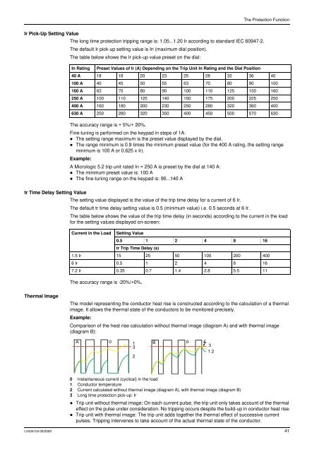
The Protection FunctionIr Pick-Up Setting ValueThe long time protection tripping range is: 1.05...1.20 Ir according to standard IEC 6<strong>09</strong>47-2.The default Ir pick-up setting value is In (maximum dial position).The table below shows the Ir pick-up value preset on the dial:In Rating Preset Values of Ir (A) Depending on the Trip Unit In Rating and the Dial Position40 A 18 18 20 23 25 28 32 36 40100 A 40 45 50 55 63 70 80 90 100160 A 63 70 80 90 100 110 125 150 160250 A 100 110 125 140 150 175 200 225 250400 A 160 180 200 230 250 280 320 360 400630 A 250 280 320 350 400 450 500 570 630The accuracy range is + 5%/+ 20%.Fine-tuning is performed on the keypad in steps of 1A:• The setting range maximum is the preset value displayed by the dial.• The range minimum is 0.9 times the minimum preset value (for the 400 A rating, the setting rangeminimum is 100 A or 0.625 x Ir).Example:A Micrologic 5.2 trip unit rated In = 250 A is preset by the dial at 140 A:• The minimum preset value is: 100 A• The fine-tuning range on the keypad is: 90...140 Atr Time Delay Setting ValueThe setting value displayed is the value of the trip time delay for a current of 6 Ir.The default tr time delay setting value is 0.5 (minimum value) i.e. 0.5 seconds at 6 Ir.The table below shows the value of the trip time delay (in seconds) according to the current in the loadfor the setting values displayed on-screen:Current in the Load Setting Value0.5 1 2 4 8 16tr Trip Time Delay (s)1.5 Ir 15 25 50 100 200 4006 Ir 0.5 1 2 4 8 167.2 Ir 0.35 0.7 1.4 2.8 5.5 11The accuracy range is -20%/+0%.Thermal ImageThe model representing the conductor heat rise is constructed according to the calculation of a thermalimage. It allows the thermal state of the conductors to be monitored precisely.Example:Comparison of the heat rise calculation without thermal image (diagram A) and with thermal image(diagram B):A 0 1 B 0323120 Instantaneous current (cyclical) in the load1 Conductor temperature2 Current calculated without thermal image (diagram A), with thermal image (diagram B)3 Long time protection pick-up: Ir• Trip unit without thermal image: On each current pulse, the trip unit only takes account of the thermaleffect on the pulse under consideration. No tripping occurs despite the build-up in conductor heat rise.• Trip unit with thermal image: The trip unit adds together the thermal effect of successive currentpulses. Tripping intervenes to take account of the actual thermal state of the conductor.LV434104 <strong>09</strong>/20<strong>09</strong> 41