W58 Circuit Breaker Catalog Pages - P&B - AeroElectric Connection
W58 Circuit Breaker Catalog Pages - P&B - AeroElectric Connection
W58 Circuit Breaker Catalog Pages - P&B - AeroElectric Connection

Create successful ePaper yourself
Turn your PDF publications into a flip-book with our unique Google optimized e-Paper software.
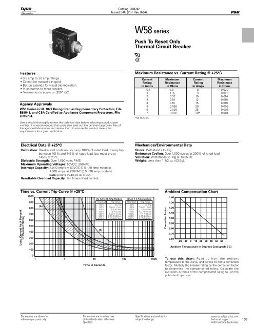
<strong>Catalog</strong> 1308242Issued 3-03 (PDF Rev. 8-04)P&B<strong>W58</strong> seriesPush To Reset OnlyThermal <strong>Circuit</strong> <strong>Breaker</strong>Features• 0.5 amp to 30 amp ratings.• Cannot be manually tripped.• Button extends for visual trip indication.• Push button to reset breaker.• Termination is screw or .250” QC.Agency Approvals<strong>W58</strong> Series is UL 1077 Recognized as Supplementary Protectors, FileE69543, and CSA Certified as Appliance Component Protectors, FileLR15734.Users should thoroughly review the technical data before selecting a product partnumber. It is recommended that users also seek out the pertinent approvals files ofthe agencies/laboratories and review them to ensure the product meets therequirements for a given application.Maximum Resistance vs. Current Rating @ +25°CCurrent Maximum Current MaximumRating Resistance Rating Resistancein Amps in Ohms in Amps in Ohms0.5 5.0 8 0.0201 1.35 9 0.0202 0.32 10 0.0143 0.18 12 0.0104 0.10 15 0.0105 0.026 20 0.0056 0.026 25 0.0067 0.020 30* 0.004*No UL/CSAElectrical Data @ +25°CCalibration: <strong>Breaker</strong> will continuously carry 100% of rated load. It may tripbetween 101% and 145% of rated load, but must trip at145% at 25°C.Dielectric Strength: Over 1,500 volts RMS.Maximum Operating Voltages: 50VDC; 250VAC.Interrupt Capacity: 2,000 amps at 50VDC (0.5 - 30 amp models).1,000 amps at 250VAC (0.5 - 30 amp models).Note: 30 0amp model not UL or CSA.Resettable Overload Capacity: Ten times rated current.Mechanical/Environmental DataShock: Withstands to 10g.Endurance Cycling: Over 1,000 cycles at 200% of rated load.Vibration: Withstands to 10g at 10-55 Hz.Weight: Less than 1 1/2 oz. (42.5g).Time vs. Current Trip Curve @ +25°CAmbient Compensation ChartLoad Current As A PercentOf <strong>Breaker</strong> Rating1000900800700600500400300200100(A)(A) All 5-30 Amp ModelsOverload Trip Times100%145%200%400%600%800%1000%(B)No TripTrip in 1 hour6.0-30 Sec.1.6-4.5 Sec.0.60-1.7 Sec.0.25-0.90 Sec.0.15-0.65 Sec.(B) All 1-4 Amp ModelsOverload Trip Times100%145%200%400%600%800%1000%No TripTrip in 1 hour10-45 Sec.3.0-14.0 Sec.1.4-7.0 Sec.0.75-4.3 Sec.0.50-3.4 Sec.Correction Factor1.401.301.201.101.000.900.800.700.60–20 –10 0 10 20 30 40 50 60Ambient Temperature In Degrees Centigrade (°C)0.1 1 10 100 1000Time In SecondsTo use this chart: Read up from the ambienttemperature to the curve, and across to find a correctionfactor. Multiply the breaker rating by the correction factorto determine the compensated rating. Calculate theoverloads in terms of the compensated rating to use thepublished trip curve.Dimensions are shown forreference purposes only.Dimensions are in inches over(millimeters) unless otherwisespecified.Specifications and availabilitysubject to change.www.tycoelectronics.comTechnical support:Refer to inside back cover.107
Ordering Information<strong>Catalog</strong> 1308242Issued 3-03 (PDF Rev. 8-04)Typical Part No. B W 58 -X B 1 A 4 A -5P&B1. Designator:W = <strong>Circuit</strong> breaker2. Series Number:58 = Single Pole, Push-to-Reset3. <strong>Circuit</strong> Function:X = Series Trip4. Button:A = White, plain, no rate marking, no trip bandB = White with red rate marking, red trip bandC = White with black rate marking, red trip bandE = White with red rate marking no trip bandF = White with black rate marking, no trip band5. Mounting Bushing:1 = 7/16” x .500” (12.70mm) long4 = 15/32” x .300” (7.62mm) long, black6 = 3/8” x .465” (11.81mm) long, round6. Terminals:A = Quick connect .250” (6.35mm) straightC = 6/32 screw 90° (screws installed)D = 6/32 screw 90° (screws bulk packed)7. Mounting Hardware:4 = Knurled nut/hex nut 15 = Two hex nuts/lock washer6 = Knurled nut/hex nut/lock washer 99 = No mtg. hardware supplied (Use C, Step #8)12 = Knurled nut/lock washerNote: For other hardware combinations, order separately. See mounting hardware Ordering Information table.8. Mounting Hardware Packaging:A = Assembled to bushingB = Bulk unassembledC = No mounting hardware9. Specify Amp Rating:0.5 3 6 9 15 30*1 4 7 10 202 5 8 12 25 *Not UL or CSAStock Items – Authorized distributors are more likely to stock the following items.<strong>W58</strong>-XB1A4A-1<strong>W58</strong>-XB1A4A-2<strong>W58</strong>-XB1A4A-3<strong>W58</strong>-XB1A4A-4<strong>W58</strong>-XB1A4A-5<strong>W58</strong>-XB1A4A-6<strong>W58</strong>-XB1A4A-7<strong>W58</strong>-XB1A4A-8<strong>W58</strong>-XB1A4A-10<strong>W58</strong>-XB1A4A-12<strong>W58</strong>-XB1A4A-15<strong>W58</strong>-XB1A4A-20<strong>W58</strong>-XB1A4A-25<strong>W58</strong>-XB1A4A-30<strong>W58</strong>-XC4C12A-1<strong>W58</strong>-XC4C12A-2<strong>W58</strong>-XC4C12A-3<strong>W58</strong>-XC4C12A-5<strong>W58</strong>-XC4C12A-7<strong>W58</strong>-XC4C12A-10<strong>W58</strong>-XC4C12A-15<strong>W58</strong>-XC4C12A-20<strong>W58</strong>-XC4C12A-25<strong>W58</strong>-XC4C12A-30Outline Dimensions.425.850 (10.80)(21.59).440(11.18)1.375(34.93).050 MAX.(1.27)CLOSED POSITION.312±.005(7.92±.13)1.375(34.93).250(6.35)CODE 6SEE TERMINAL DRAWINGSSEE MOUNTINGFOR DETAILBUSHING ANDMOUNTING HARDWARE DRAWINGS FOR DETAIL.660(16.76)CODES 1 & 415.281 MAX.(7.14)OPEN POSITIONBUTTONTerminal Options.415(10.54)1.375(34.93)A.250 (6.35) x .032 (.81)QUICK CONNECT TERMINALS.187(4.75).425(10.80).850(21.59).440(11.18).312 TYP.(7.92)C & D .156.85(3.96)(21.6)#6-32 SCREW& LOCK WASHER ASSEMBLY108Dimensions are shown forreference purposes only.Dimensions are in inches over(millimeters) unless otherwisespecified.Specifications and availabilitysubject to change.www.tycoelectronics.comTechnical support:Refer to inside back cover.
<strong>Catalog</strong> 1308242Issued 3-03 (PDF Rev. 8-04)Mounting HardwareDisc Hex Nut Knurled Nut Lockwasher Pal NutP&BBLACK ETCHED LETTERS.078 (1.98) HIGH, BOLD FACESTRAIGHT KNURL24 PITCHALTERNATE TEETH TWISTEDIN OPPOSITE DIRECTIONSCIRCUIT BREAKERPRESS TO RESETA FLAT AA.937(23.80).013(.33)BBBABMounting BushingType 17/16-28 THREAD(SILVER)Type 4.300(7.62)15/32-32 THREAD(BLACK)Type 6.465(11.81)Recommended Cutout.440 - .450 DIA.(17.3 - 17.7).470 - .480 DIA.(18.5 - 18.9).370 - .380 DIA.(15.0 - 15.3)Mounting Hardware DimensionsDim. Hex. Knurled L/W Pal3/8” .556 .562 .562 .562A. 7/16” .625 .625 .540 .62515/32” .556 .625 .600 .6253/8” .085 .078 .018 .140B. 7/16” .111 .125 .022 .11115/32” .078 .125 .018 .090Mounting Hardware Ordering InformationMountingPush toBushing Knurl Hex Pal ResetCode Nut Nut Nut Washer Disc1 55-010A 55-011A 16S086B 88-021B 33-012A4 • 55-001B 16S086C 88-002A 33-012C6 55-008A 55-001D 16S086A 88-006K 33-012B• 55-010B (silver) 55-010E (black)3/8-24 THREAD(SILVER)Dimensions are shown forreference purposes only.Dimensions are in inches over(millimeters) unless otherwisespecified.Specifications and availabilitysubject to change.www.tycoelectronics.comTechnical support:Refer to inside back cover.109
![G-Series-Ext [pdf] - Carling Technologies](https://img.yumpu.com/50918301/1/190x245/g-series-ext-pdf-carling-technologies.jpg?quality=85)