Ramp/Soak Controller - Cascade
Ramp/Soak Controller - Cascade
Ramp/Soak Controller - Cascade

Create successful ePaper yourself
Turn your PDF publications into a flip-book with our unique Google optimized e-Paper software.
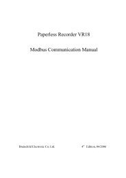
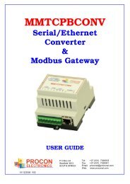
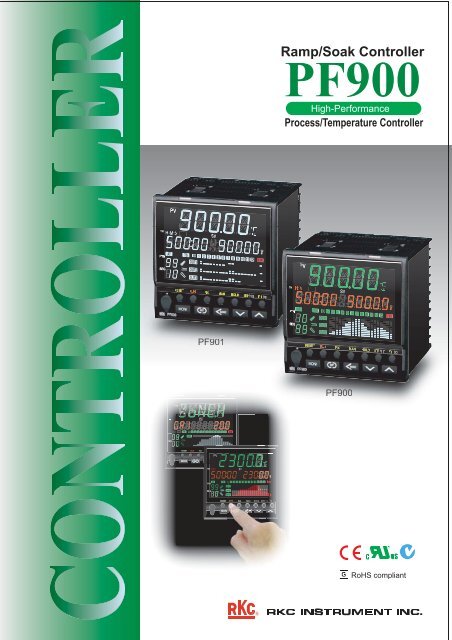
RESET RUN FIX MAN HOLD STEP P SET PTN END<strong>Ramp</strong>/<strong>Soak</strong> <strong>Controller</strong>PF900High-PerformanceProcess/Temperature <strong>Controller</strong>TMTMPF901PF900SVREM TS DOALMOUT1OUT2OUT3MONIPVTMH MSVPTNSEGAT TS DOAOUT1OUT2OUT3RESET RUN FIX MAN HOLD STEP P SETMONIRoHS compliantR
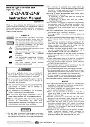
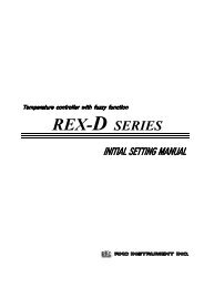
DisplayHigh Intensity DisplayAll necessary information is visible onthe easy-to-read front display.Display with 11-segment charactersProgram/Segmentremaining time display(Unit: hour:min/min:sec)Time signal/Digital outputindicatorsEVOLUTIONHigh intensitywhite color displayOutput program memorygroup number set valueWait zone High (group 1)set valueRunning pattern/Segment displayGradientstate displayProgram pattern/Output bargraph displayControlAdvanced controlNew control algorithmRSS (<strong>Ramp</strong> <strong>Soak</strong> Stabilizer)A newly developed control algorithm designed exclusively forramp/soak controls improves follow-up performance whilesimultaneously suppressing overshoot at the transition fromramp to soak.PVSVSuppress overshoot<strong>Ramp</strong>Improvedfollow-up<strong>Soak</strong>EVOLUTIONProgramControlEVOLUTIONPF900Newest technology provides versatilefunctionality and features to satisfyrequirements in a wide range ofapplications.Multiple controlMaximum of 3 point program pattern outputs(Output program function)Up to 3 analog outputs can be used to control three types of devices (such as a motorized valve).Combining time signal outputs allows programming for complex applications.Time signal outputOUT1OUT2OUT3Analogoutput tAnalogoutput tAnalogoutput t100%0%00%%00%%CatalyticMSteamM2Warm waterMMotorizedvalveFast sampling of 0.05 sec.Meet different control requirements by switching sampling speeds.Choose 0.05 for "fast" process applications to 0.25 sec. samplingfor "stable" for applications which require higher resolutions.Maximum of 11 digital inputs and 12 digital outputVersatile event handling is achieved with an abundance of digitalinput/output options including the addition of a wait release andswitchover of reverse/direct action.Customizable keysDirect access to major functionsRESET RUN FIX MAN HOLD STEP P SET PTN ENDMONIVentilationvalveCustomize the function keys you want toaccess at a touch by:• Press once,• Press twice,• Pressing the key for 2 seconds• Disabled
TMProgramEVOLUTIONLarge memoryThe PF900 can store up to 1024 segments (99 patterns with 10 segments each to 10 patterns with 99 segments each).(32 patterns by 32 segments, yet all patterns are linkable to form a large program)Time signal outputEnhanced flexibilityPatternSegment signal outputEach segmentTwo types of signal modesYou can select a pattern mode that works withinthe pattern or a segment mode that works withinthe segment. (Please specify one of the two )TS1TS1Selectable PID zonesTS8TS8Level-PID or segment PIDSelect the best PID option for your application.The set values are stored in 8 stage levels orin 8 memory groups.Satisfies versatile applicationsSet values managementTMFlexible pattern end outputSet the end signal to the control mode after thepattern end, valve opening status, event status,or retransmission output signal status.Flexible WAIT functionThe WAIT function can be released by the out-ofwaitzone determination (upper/lower sides),digital input or timeout setting.Memory groupSet values of P, I, D, event, segment wait, timesignal, program pattern output can be storedin memory groups and can be called up fora segment to be set.• PID values, Wait and Events: 8 groups• Time signals: 16 groups• Program pattern output : Up to 99 pointsSegment repeatSpecified segment can be repeated.mmunicationEVOLUTIONReliable collaboorative operationCollaborative program operation( Inter-controller communication)Up to 4 slave instruments (FB/RB series and PF900/901) canbe connected via exclusive communication port.Digital communicationn gives isolated communication withoutsetting error, ratio setting of individual slave controller,memory area selection and Run/Stop switchover.PF900(Master)COM2Inter-controllerCOMCOM1RS-485(MODBUS)COM1COM1COM1FB100FB100FB100FB100(Slave) (Slave) (Slave) (Slave)Easy data managementFront loader interface + Programming toolThe PF900 comes with a front loader port and programmingtool making complicated programming visual and simple toplace on a PC. Downloading or Uploading large numbers ofset values can be achievedwith ease.• Memory area needs to be selected on FB series.• If you use FB400, FB900 or PF900 for a slave device, please select Communication 1.Communication protocol among slave devices is Modbus.• Models available as a master devicePF900/PF901 : Suffix codes for communication : W, X, or Y• Models available as a slave deviceFB100 : Optional codes : E, F, H, or JFB400/FB900 : Suffix codes for communication : 5 or XRB100/RB400/RB500/RB700/RB900 : Suffix codes for communication : 5, 6, B or CPF900/901 : Suffix codes for communication : 5 or XUSB communicationconverterCOM-K-3(With loader communication cable)COM-K-N(Without loader communication cable)USB port COM-KLoader comUSB(Loader cable)(USB cable comes with COM-K) Model code for cable only :(Complete with loader communication W-BV-03-1500cable for PF900)(Front loader port)3
Specifications4InputInputSampling timeInfluence of externalresistanceInfluence of leadresistanceInput break actionDigital filterPV biasPV ratioSquare rootextractionControl methodAutotuningControlAutotuning withauto soak detect:Setting rangeLevel-PIDValve driveControl motor timeIntegrated outputlimiterNeutral zoneDifferential gapValve actionat RESET statePerformanceMeasuringaccuracy• Universal inputa) Temperature, current, voltage (low) input groupThermocouple inputK, J, E, T, R, S, B, N, PLII, W5Re/W26Re, U, L, PR40-20RTDPt100, JPt100 (3-wire type)DC Voltage input (input impedance: 1MΩ)0 to 1V, 0 to 100mV, 0 to 10mV,-100 to +100mV, -10 to +10mV, -1 to +1Vb) Voltage (high) input groupDC Voltage input (input impedance: 1MΩ)0 to 5V, 1 to 5V, 0 to 10V, -5 to +5V, -10 to +10Vc) Current input groupDC Current input (input impedance: 50Ω)4 to 20mA, 0 to 20mA(Use dip switch to change input group.)0.1 sec (0.05sec/0.25sec is selectable.)0.2μV/Ω (Thermocouple input)Approx. 0.01% of span (for RTD)• Maximum 10Ω per leadwire maxthermocoupleThermocouple input : Up-scale/Down-scale (Selectable)RTD input : Up-scaleLow voltage input : Up-scale/Down-scale (Selectable)Current input : Value around 0mAHigh voltage input : Value around 0V0.1 to 100.0 sec. (OFF when 0 is set.)- input range span to + input range span0.001 to 9.999PV = (Input value) x PV ratio + PV biasLow level cut off : 0.00 to 25.00% of spana) Brilliant II PID control• Direct action/Reverse action is selectableb) Brilliant II PID control (Heat/Cool type)c) Brilliant II position proportioning control• Direct action/Reverse action is selectable• Position proportional control can be used with/without FBR(feedback resistance) input.• a), b), c) selectablea) For PID control or position proportioning controlb) For Heat/Cool PID control (For extruder, air cooling)c) For Heat/Cool PID control (For extruder, water cooling)d) For Heat/Cool PID controlThis is a function to search program soak areas and performautotuning in the order of segments at the time of reset.• This feature is enabled/disabled for ramp segment.a) Proportional band:0 (0.0/0.00) to input span (°C,°F) (for temperature input)0.0 to 1000.0% of input span (for voltage/current input)(ON/OFF control when P = 0)• Differential gap at ON/OFF control (High/Low individual setting)Temperature input : 0 (0.0/0.00) to input span (°C,°F)Voltage/Current input : 0.0 to 100.0% of input spanb) Integral time: 0 (0.0) to 3600 (3600.0) sec.(PD control when I = 0)c) Derivative time: 0 (0.0) to 3600(3600.0) sec.(PI control when D = 0)d) Cooling proportional band :1 (0.1/0.01) to input span (°C,°F) (for temperature input)0.1 to 1000.0% of input span (for voltage/current input)e) Integral time for cooling : 0 (0.0) to 3600 (3600.0) sec.(PD control when I = 0)f) Derivative time for cooling : 0 (0.0) to 3600(3600.0) sec.(PI control when D = 0)g) Overlap/deadband:-span to +span (°C,°F) (for temperature input)-100.0 to +100.0% of span (for DC voltage/current input)h) Control response parameter: slow, medium, fasti) Output limiter: -5.0 to +105.0% (High/Low individual setting)j) Cool side output limiter: -5.0 to +105.0%(High/Low individual setting)k) Heat side cycle time: 0.1 to 100.0 sec.l) Cool side cycle time: 0.1 to 100.0 sec.m) Manual reset: -100.0 to +100.0% of proportional bandn) Output at reset: -5.0 to +105.0%(Heat and cool sides are individual setting.)o) Overlap/deadband reference: 0.0 to 1.0 (heating reference at zero)p) Undershoot suppression factor (USS) for cooling:0.000 to 1.000q) <strong>Ramp</strong>/soak stabilizer (RSS): 0.0 to 1.0• Selectable from enabled/disabled.a) Number of levels: 8 levels (PID groups 1 to 8)b) Level setting range: Low limit of input range to high limit ofinput range (level settings 1 to 7)5 to 1000 secondsOFF, 0.1 to 200.0% of control motor time0.1 to 20.0%50% of neutral zone (Fixed)a) close: off, open: offb) close: on, open: offc) close: off, open: on• a), b), c) selectablea)ThermocoupleType : K, J, T, E, PLII, U, LLess than -100°C (-148°F) : ±1.0°C (±1.8°F)-100 to +500°C (-148 to 932°F) : ±0.5°C (±0.9°F)More than 500°C (932°F) : ±0.1% of readingType : N, S, R, W5Re/W26ReLess than 0°C (32°F) : ±2.0°C (±3.6°F)0 to 1000°C (32 to 1832°F) : ±1.0°C (±1.8°F)More than 1000°C (1832°F) : ±0.1% of readingMeasuringaccuracyProgram controlTime accuracyNumber ofprogram patternsNumber ofprogram segmentsSegment timeNumber ofsegment repeatNumber ofpattern repeatNumber oflinkable patternsPattern endoutput time:Time signal memorygroup numberProgram startingmode:WAIT status at thetime of program start:WAIT functionPattern end outputTime signal output:Programmedpreset manualoutput:(Output programfunction)Other features:Memory groupPID memoryEvent memorySegment wait memoryTime signal memoryProgram patternoutputType BLess than 400°C (752°F) : ±70.0°C (±126°F)400 to 1000°C (752 to 1832°F) : ±1.4°C (±2.6°F)More than 1000°C (1832°F) : ±0.1% of readingType PR40-20Less than 400°C (752°F) : ±20°C (36°F)400 to 1000°C (752 to 1832°F) : ±10°C (18°F)More than 1000°C (1832°F): ±0.1% of displayed value• Cold junction temperature compensation error±1.0°C (1.8°F) [Between 5 and 40°C (41 and 104°F)]±1.5°C (2.7°F) [Between -10 and 5°C (16 and 41°F), and40 and 55°C (104 and 122°F)]b) RTDLess than 200°C (392°F) : ±0.2°C (±0.4°F)More than 200°C (392°F) : ±0.1% of readingc) DC voltage and DC current±0.1% of span±0.01% of reading or input sampling time, whichever is larger.Up to 99 patternsUp to 1024 segments• Up to 99 segments per pattern.• Supplied with hold, step, fast forward, fast rewind features.0 hr 0 min to 500 hs 00 min or 0 min 0 sec to 500 min 0 sec1 to 9999 repeats• Repeat is disabled when set to 1.1 to 10,000 repeats• Continuous repeat when set to 10,000.0 to 99 patterns• No pattern link when set to zero0 hr 0 min to 500 hs 00 min or 0 min 0 sec to 500 min 0 sec• Output remains on when set to zero.0 to 16• No assigned groups when set to zero.a) Starts from a desired value (SV after reset)b) Starts from a desired measured input (Time fixed)c) Starts from a desired measured input (Time shortened)d) Intersection of measurement input and pattern is searchedand starts from there. (HOLD status when started)e) Intersection of measurement input and pattern is searchedand starts from there. (RUN status when started)WAIT condition memory number : 0~8• No WAIT when set to zero.• Selectable from release by wait zone, contact input (trigger), andtimeout.a) Wait zone (upper)1) Temperature input: 0 (0.0/0.00) to 200 (200.0/200.00)(°C,°F)2) Voltage/current input: 0.0 to 20.0% of input span• Wait function off when set to zerob) Wait zone (lower)1) Temperature input: -200(-200.0)~0(0.0)(°C,°F) or-199.99~0.00(°C,°F)2) Voltage/current input: 20.0~0.0% of input span• Wait function off when set to zeroc) Wait timeout(Time counting resumes unconditionally after the set time has elapsed)0 hr 0 min to 500 hs 00 min or 0 min 0 sec to 500 min 0 sec• Function is disabled when set to zero.• DO can be assigned (turns on for 0.5 second for each pattern repeat).Time signal or segment signal, whichever is specified.a) Time signal1) Number of outputs: 8 (TS1 to TS8)2) Output assignment: Up to 12 (including 4 relays), assignable by DO3) Time signal memory group: 16 groups4) Number of memory storage: 16 groups X 16 memories5) Number of storage memory: 1 to segment No. (max = 99)6) Starting time: 0 hr 0 min to 500 hs 00 min or0 min 0 sec to 500 min 0 sec7) Ending segment: 1 to segment No. (max = 99), however, endingsegment must be equal to or larger than the startingsegment.8) Ending time: 0 hr 0 min to 500 hs 00 min or0 min 0 sec to 500 min 0 secb) Segment signal: TS1 to TS8 can be independently turned ON andOFF at each segment.Fixed value is produced at each segment.The function is activated by assigning outputs 1 to 3 to theprogram output.a) Number of output program patterns:1 to (128/max. segments number)For example, in case of 99 segments, it is "1".• Max. segment No.: Number of segments by number ofpatterns multiplied by number of segments.b) Setting items: Output program 1 to 3 : -5.0 to +105.0%(Independently adjustable).Pattern/segment copy function, tag name edit function (for eachpattern), data clear (to initial state), remaining time display ofpattern.a) Memory group No : 0 to 8 (Level-PID is activated when set to zero.)b) Setting items:Proportional band, Integral time, Derivative time, Control responseparameter, Cool side proportional band, Cool side integral time, Coolside derivative time, Deadband/overlap, Neutral zone, Manual reset,Output limiter (high/low), Cool side output limiter (high/low), ON/OFFdifferential gap (high/low), LBA time, LBA headband.a) Memory group No.: 0 to 8 (event off when set to zero)b) Setting items : Event 1 to 4a) Memory group No.: 0 to 8 (wait off when set to zero)b) Setting items: wait zone, wait release trigger, timeout for waita) Memory group No.: 0 to 16 (time signal off when set to zero)b) Memory No. : 1~16 (16 set points per group)c) Setting items: Time signal output destination, starting segment,time signal starting time, end segment, time signal end time.a) Pattern Nos.: 1 to (128/max.segment) • Up to 99 segmentsb) Segment No.: 1 to max segment value.c) Setting items : Output program 1 to 3
Mode selectionOperation modeMode transferBefore transferReset modeProgramcontrolmodeFixedsetpointcontrolManualcontrolNumber of outputOutput functionOutput types:Reset modeProvidecontroloutput atthe timeof resetOutput (OUT)Digital output (DO)Number ofoutputOutput functionOutput typesEvent (alarm) functionNumber of eventEvent typesEvent settingrangeEvent outputtypeAdditionalfeatures forevent output:Heater breakalarm (HBA)Reset (RESET), program (RUN), fixed setpoint control (FIX), andmanual control (MAN)Action when operation mode is selected.After transferProgram control Fixed setpointControl continues with thecalculated value of the control.*1Control continueswith the SV for aprogram control.Control continueswith the SV for afixed setpointcontrol.Control continues after bumplesstransfer to manual outputRetransmission output (AO)Manual controlControl starts withthe control output atreset as the manualsetpoint.Output continuesafter adjusting thefinal output level ofthe program controlto the output level ofmanual.Output continues afteradjusting the finaloutput level of thefixed setpoint controlto the output level ofmanual.*1 Program status is retained unless the instrument is reset. If program control is selected, controlstarts from the retained status.• Output may result in a bump in spite of a bumpless transfer action if the selected control modeis P action, PD action, or ON/OFF action.Up to 3 points(OUT1 to OUT3)Control output (MV), Output program, Retransmission output.OUT2 and OUT3 can be used as event outputs.• See output assignment table for details.a) Relay contact output : Form 1a contact,Rating: 250V AC 3A (Resistive load)Electrical life: 300,000 cycles or moreb) Voltage pulse output : 0/12V DC,Load resistance : 600Ω or more (20mA or less)* OUT1 can be 300Ω or more (40mA or less) if OUT2 is not used.c) Current output : 4 to 20mA, 0 to 20mA DC,Load resistance: 600Ω or lessd) Continuous voltage output : 0 to 5V, 1 to 5V, 0 to 10V,0 to 1V DC (Assignable to OUT3 only),Load resistance: 1KΩ or moree) SSR output (triac output) : current rating 0.5Af) Open collector output (sink method) : Load voltage 30V DC or lowerAllowable load current: 100mA.ON voltage: 2V or less (For maximum load current)DO1 to DO4 : StandardDO5 to DO12: OptionalUp to 12 points (DO1up to 12 (DO1 to 12)DO1 to 4 : Relay contact output (Standards)DO5 to 12 : Open collector output (Optional)Time signal, event, Heater break alarm, Loop break alarm, Inputabnormality, RUN state, FIX mode state, MAN mode status, <strong>Ramp</strong>status, <strong>Soak</strong> status, HOLD status, WAIT status, Pattern end status, ATstatus, FAIL, Communication failure, FBR input abnormalitya) Relay contact output, Form 1a contact, 250VAC 1A (Resistive load)b) Open collector output (sink type), Load voltage: 30V DC or lessAllowable load current : 100mAON voltage : 2V or less (For maximum load current)(Optional)Number of output Up to 2 points (3 for program outputs) • Depends on output assignment.Output function PV, SV, Control output, Output program value, Deviation,% of segment time (Selectable)Output types a) Current output : 4 to 20mA, 0 to 20mA DCLoad resistance : 600Ω or lessb) Voltage output : 0 to 1V, 0 to 5V, 1 to 5V, 0 to 10V DCLoad resistance : 1KΩ or moreScaling range a) PV, SV : Same as input rangeb) Control output, Output program output: 0 to 100%c) Deviation: ±input spanOutput program and segment time percentage are fixed.Additional function Stop/continue selectable during RESET status(Optional)Up to 4 points (event 1 to 4)Process, Deviation, Band, SV, MVa) Deviation/BandEvent setting: -input span to +input spanDifferential gap for event action: 0 to input spanb) PV/SVEvent setting: same as input rangeDifferential gap for event action: 0 to input spanc) MVEvent setting : -5.0 to +105.0%Differential gap for event action : 0 to 110%Freely assignable to digital outputs (DO1 to 12, OUT2, OUT3).See Output allocation table for details.a) Hold function (Valid when power is supplied or when even is started.)b) Event action selection at the time of abnormal input.c) Action selection at the time of RESETd) Delay timer: 0.0 to 600.0 sec.e) Event minimum ON and OFF time : 0.0 to 600.0 sec (ON/OFF individual setting)f) Interlock : Without/With/Switches into the manual mode and stops control.a) Number of CT input: 2 points (1 for each CT input)b) Input function: Current detector (CT)c) Input range: CTL-6-P-N: 0 to 30ACTL-12-S56-10L-N: 0 to 100Ad) Heater current display range:0.0 to100.0Ae) Heater current display accuracy: ±5% of input value or ±2Af) Interlock : Without/With/Switches into the manual mode and stops control.g) Output method: Freely assignable to digital outputsh) Action selection at reset status• Heater break alarm (HBA) is not available for current/continuous voltage output.Loop breakalarm (LBA)Digital input (DI)Number of inputInput typeFunctionsFeedback resistance (FBR) inputAllowableresistanceSampling timeCommunicationCommunicationmethodProtocol:CommunicationspeedBit structureMaximumconnection:Inter-controller communication[COM2]Communication Function to send target value to slave controllers.typeCommunication RS-485methodProtocol Modbus RTUCommunication 9600, 19200, 38400 bps.speed(selectable)Bit structure Start bit: 1, Data bit: 8, Parity bit: none, Stop bit: 1Maximum slaves 4 unitsSlave controllers PF900/PF901/FB series (With memory area), RB series (with memory area)Loader communicationCommunication RS-485methodProtocolCommunicationspeedBit structureConnectionmethodGeneral specificationsSupply voltagePowerconsumptionRush currentPower failureInsulationresistancea) LBA time: 0 to 7200 sec. (OFF when set to zero)b) LBD setting: 0 to input spanc) Interlock : Without/With/Switches into the manual mode and stops control.d) Output method: Freely assignable to digital outputsSee output assignment table.• Loop break alarm (LBA) is not available for heat/cool PID control type.DI1 to DI6 : OptionalDI7 to DI11: StandardUp to 11 points (DI1 to 6, DI7 to 11)Non voltage contact inputDI1 to DI6 : Pattern No. selection + Pattern set, WAIT releaseDI7 to DI11 : Pattern No selection + Pattern set, Mode selection (RESET,RUN), Direct/Reverse action selectionRefer to Digital Input table for details.100 to 10KΩ (135Ω as standard)0.1 sec. (For measurement input sampling 0.05 sec.)0.2 sec. (For measurement input sampling 0.1 sec.)0.5 sec. (For measurement input sampling 0.25 sec.)(Optional)RS-485/RS-422A/RS-232C(To be specified at the time of ordering)a) RKC standard (ANSI X3.28 subcategory 2.5 A4)b) Modbus RTU(selectable)2400, 4800, 9600, 19200, 38400, 57600 bps.(selectable)a) RKC protocol:Start bit:1, Data bit: 7 or 8, Parity bit: 1 (even or odd) or noneStop bit: 1 or 2b) Modbus protocolStart bit: 1, Data bit: 8, Parity bit: 1 (even or none), Stop bit: 1 or 2• a) or b) selectableRS-485/RS-422A : 31 unitsRS-232C : 1 unitRKC standard (ANSI X3.28 subcategory 2.5 A4)38400 bps(Optional)Start bit:1, data bit: 8. parity bit: none, stop bit: 1Front: Connected to COM-K with an exclusive cable (W-BV-03-1500)• Front loader interface is available only while instrument is powered.a) 85 to 264V AC (50/60Hz), Rating: 100 to 240V ACb) 20.4 to 26.4V AC (50/60Hz), Rating: 24V ACc) 20.4 to 26.4V DC, Rating: 24V DCa) 100 to 240V AC : 13.5VA ( at 240V AC),9.5VA (at 100V AC)b) 24V AC : 8.5VA c) 24V DC : 230mA < > : Power saving modea) 100 to 240V AC : Less than 17.5A (at 240V AC),Less than 7.5A (at 100V AC)b) 24V AC : Less than 8.5Ac) 24V DC : Less than 6.0AA power failure of 20m sec or less will notaffect the control action. If power failure of morethan 20m sec occurs, controller will restart with the stateof HOT start 1, HOT start 2 or COLD start (selectable)Memory backup Backed up by Nonvolatile memory (FRAM)• Data retaining period : Approx. 10 years• Number of writing : Approx. 10,000,000,000 times.(Depending on storage and operating conditions.)Power savingmode(Optional)Not available whenCT input is supplied• Position proportional control can be used with/without FBR (feedback resistance) input.If any key is not pressed during the user set time period, the backlightLED is turned off except PV and ALM displays.Setting time: 0 to 60 min (0 for no power saving mode)• Back to normal display if any key is pressed during the power saving mode.20MΩ or more (500V DC) between input and ground terminals.20MΩ or more (500V DC) between power and ground terminals.20MΩ or more (500V DC) between input and power terminals.1500V AC for one minute between input and ground terminals.1500V AC for one minute between power and ground terminals.Dielectricstrength2300V AC for one minute between input and power terminals.Ambient temperature -10 to +55°CAmbient humidity 5 to 95%RH (Non condensing)• Absolute humidity : MAX.W.C29.3g/m 3 dry air at 101.3kPaWeight Approx. 470g,Waterproof/ NEMA type 3 : IP55 (When mounted in a panel, front direction)DustproofSafety standards CE marking, UL, cUL, C-Tick[COM1]5
Model codeSpecificationsOutput 1(OUT 1)Control output orOutput program *1Output 2(OUT 2)Control output,Output program,Retransmissionoutputor Digital output *1Output 3(OUT 3)Output program,Retransmissionoutputor Digital output *1Supply voltageDigital outputCT input orFBR input96 x 96mm DIN sized ramp/soak controllerPV : Green, SV : Orange, Pattern : White PF900PV : White, SV : White, Pattern : White PF901Relay contact outputSSR drive voltage pulse output (0/12V DC)DC current/voltage output See output tableTriac outputOpen collector outputNoneRelay contact outputSSR drive voltage pulse output (0/12V DC)DC current/voltage output See output tableTriac outputOpen collector outputNoneSSR drive voltage pulse output (0/12V DC)DC current/voltage output See output tableOpen collector output24V AC/DC100 to 240V ACDO: 4 points, Relay : DO 1 to 4Model and Suffix CodeHardware coding onlyDO:12 points, Relay DO 1 to 4, Open collector: DO 5 to 12NoneCT input: 2 pointsFBR (FeedBack Resistance) inputNoneCommunication COM1:RS-232C COM2:Not supplied • Digital input: 6 points, DI 1 to 6Digital input(DI 1 to 6)COM1:RS-422ACOM1:RS-485COM1:RS-232CCOM2:Not suppliedCOM2:Not suppliedCOM2:RS-485• Digital input: 6 points, DI 1 to 6• Digital input: 6 points, DI 1 to 6• Digital input: 6 points, DI 1 to 6COM1:RS-485 COM2:RS-485 • Digital input: 6 points, DI 1 to 6• DI7 to 11 suppliedas standard COM1:Not supplied COM2:RS-485 • Digital input: 6 points, DI 1 to 6Digital input: 6 points, DI 1 to 6Quick startNonecode Specify quick start code 1Specify quick start code 1 and 2 (See page 7)No quick start codePID control with AT (Reverse action)PID control with AT (Direct action)Control Heat/Cool PID control with ATMethod Heat/Cool PID control with AT for extruder (Air cooling type)Heat/Cool PID control with AT for extruder (Water cooling type)Position proportioning PID control with AT (Reverse action)Position proportioning PID control with AT (Direct action)Input and No quick start coderange See Input range Code TableInstrument version Version symbolQuick start code 1*2, *3MVTDNMVTDNVD344CNTFN145WXYDN12Quick startcode 1No codeFDGAWZCNo code/Y/YIf inter-controller communication (master-slave operation) is used,select code: W, X, or Y (that means "with communication 2")for a master device, and 5 or X (communication 1: RS-485) for a slavedevice.*1 For program or retransmission output, specify voltage or current.For digital output, specify relay or open collector output.*2 Heater break alarm (HBA) is not available or current/continuous voltageoutput.Loop break alarm (LBA) is not available for heat/cool PID control type.*3 Position proportional control can be used with/without FBR (feedbackresistance) input.Control output (OUT1, OUT2) assignment by control actionPID control action:Control output is produced from OUT1. OUT2 can be used asretransmission output or digital output.Heat/Cool PID control action:Heating output is produced from OUT1 and cooling output from OUT2.Position proportioning PID control action:Opening output is produced from OUT1 and closing output from OUT2.Output Code TableOutput Type0 to 1V DC *10 to 5V DC0 to 10V DCCode345Output Type1 to 5V DC0 to 20mA DC4 to 20mA DC*1: 0 to 1 V DC output can be specified only forOutput 3 (Analog retransmission output).Code678Input Range Code TableThermocoupleRTDInputKJECodeK 35K 42K 23K 09K 41K 02K 06K C9K B4K A4K C5J 27J 29J 16J 15J C9J B5J B6J B9E 20E 17E 08E 06E B3E A6E B1Range-200.0 to +400.0°C-200.0 to+1372.0°C0.0 to 1300.0°C0.0 to 400.0°C-200 to +1372°C0 to 400°C0 to 1200°C-328.0 to +2502.0°F0.0 to +2400.0°F0.0 to 800.0°F-328 to +2502°F-200.0 to +400.0°C-200.0 to+1200.0°C0.0 to 1200.0°C-200 to +1200°C-328.0 to +2192.0°F0.0 to 2100.0°F0.0 to 800.0°F-328 to +2192°F-200.0 to +1000.0°C-200.0 to +200.0°C0.0 to 1000.0°C-200 to +1000°C-328.0 to +1832.0°F0.0 to 1800.0°F-328 to +1832°FInputTSRBNCodeT 19T 13T 06T 16T C2T B7T A7T C9S 04S 07S 06S A8S A5S A7R 05R 08R 07R A8R A5R A7B 04B 03B A9B B3B B2N 05N 02N A8N A4N A7Range-200.0 to-200.0 to+400.0°C+200.0°C0.0 to 400.0°C-200 to +400°C-328.0 to-300.0 to+752.0°F+700.0°F0.0 to 700.0°F-328 to +752°F0.0 to1700.0°C-50.0 to+1768.0°C-50 to +1768°C-58.0 to +3214.0°F0.0 to 3200.0°F-58 to +3214°F0.0 to 1700.0°C-50.0 to +1768.0°C-50 to +1768°C-58.0 to +3214.0°F0.0 to 3200.0°F-58 to +3214°F0.0 to 1800.0°C0 to 1800°C0.0 to 3200.0°F0.0 to 3272.0°F0 to 3272°F0.0 to 1300.0°C0 to 1300°C0.0 to 2372.0°F0.0 to 2300.0°F0 to 2372°FInputPLII(NBS)W5Re/W26Re(ASTM)L(DIN)U(DIN)PR40-20CodeA 06A 05A 02A A7A A5A A2W 04W 06W 03W A8W A6W A2L 04L 05L A6L B1L A3U 04U 08U B1U B3U B4F 01F 02F A1F A2Range0.0 to 1390.0°C0.0 to 1300.0°C0 to 1390°C0.0 to 2534.0°F0.0 to 2300.0°F0 to 2534°F0.0 to 2300.0°C0.0 to 1200.0°C0 to 2300°C0.0 to 4200.0°F0.0 to 2200.0°F0 to 4200°F0.0 to 900.0°C0 to 900°C0.0 to 1600.0°F0.0 to 1652.0°F0 to 1652°F0.0 to 600.0°C0 to 600°C0.0 to 1100.0°F0.0 to 1112.0°F0 to 1112°F0.0 to 1800.0°C0 to 1800°C0.0 to 3200.0°F0 to 3200°FInput Code RangeD 34 -100.00 to+150.00°CD 35 -200.0 to +850.0°CD 21 -200.0 to +200.0°CD 25 -200.0 to +600.0°CPt100D 36 -200 to +850°CD C9 -328.0 to +1562.0°FD B8 -300.0 to +1200.0°FD D2 -328 to +1562°FP 29 -100.00 to+150.00°CP 21 -200.0 to +200.0°CJPt100P 26 -200.0 to +600.0°CP 30 -200.0 to +640.0°CP 10 0.0 to 500.0°CP 31 -200 to +640°CDC Current • VoltageInput0 to 10mV0 to 100mV0 to 1V0 to 5V0 to 10V1 to 5V0 to 20mA4 to 20mA-100 to +100mV-1 to +1V-10 to +10mV-10 to +10V-5 to +5VCode1 012 013 014 015 016 017 018 019 019 029 039 049 05Range-19999 to +32000(Programmable)Factory set value:0.0 to 100.0%6
Quick start code 2• Quick start code 2 tells the factory to ship with each parameter preset to the values detailed as specified by the customer.Quick start code is not necessarily specified when ordering, unless the preset is requested.These parameters are software selectable items and can be re-programmed in the field via the manual.Quick start code 2Specifications(Initial setting code)Digital input allocation See Digital Input Allocation tableDigital output 1 type See Digital output code tableDigital output 2 type See Digital output code tableDigital output 3 type See Digital output code tableDigital output 4 type See Digital output code tableNo CT1 and CT2CT1 : CTL-6-P-N, CT2 : No useCT typesCT1 : CTL-12-S56-10L-N, CT2 : No useCT1 : CTL-6-P-N, CT2 : CTL-6-P-NCT1 : CTL-12-S56-10L-N, CT2 : CTL-12-S56-10L-NNo communication 1 (COM1)Communication 1 ANSI/RKC standard protocolMODBUS protocol• COM2 is used exclusively for inter-controller communication.• Default setting value of Digital output typeDigital output 1 : Deviation HighDigital output 2 : Deviation Low with HoldDigital output 3 : Time signal 1Digital output 4 : Pattern end output*1 Heater break alarm (HBA) is not available for current/continuous voltage output.*2 Loop break alarm (LBA) is not available for heat/cool PID control type.Digital Input allocation tableNPSTUN12Digital output code table (Programmable)Event typesCodeNo eventDeviation HighNADeviation LowBDeviation High/Low (Common high/low setting)Band (Common high/low setting)Deviation High with HoldDeviation Low with HoldDeviation High/Low with Hold (Common high/low setting)Process HighProcess LowProcess High with HoldCDEFGHJKProcess Low with HoldLHeater Break Alarm (HBA) 1 *1PHeater Break Alarm (HBA) 2 *1QLoop Break Alarm (LBA) *2RFAILSFBR Input AbnormalityTBand (Individual high and low settings)USet value HighVSet value LowWDeviation High/Low (Individual high and low settings) XDeviation High/Low with Alarm Hold (Individual high and low settings) YMV value High1MV value Low2Cool side MV value High3Cool side MV value Low4Time signal 1Time signal 2Time signal 3Time signal 4Pattern end output56789Code012345DI1 DI2DI3DI4 DI5DI6 DI7 DI8 DI9 DI10DI11Pattern No. SelectionPattern No. Set RESET RUN STEP HOLD Pattern No. SelectionPattern No. SelectionPattern No. Set RESET RUN STEP Pattern No. SelectionWAIT release WAIT release WAIT release WAIT release WAIT release WAIT release Pattern No. SelectionPattern No. SetWAIT release WAIT release WAIT release WAIT release WAIT release WAIT releasePattern No. SelectionWAIT release WAIT release WAIT release WAIT release WAIT release WAIT release RESET RUN STEP HOLD Direct/Reverse selectionWAIT release WAIT release WAIT release WAIT release WAIT release WAIT release RESET RUN STEP HOLD Pattern No. Selection (Increment)Example of Model Code and Quick start codeModel codeSpecificationsInput: Thermocouple PR40-20, Max.1800°C, resolution 0.1°CControl: Heating control (Output: 4 to 20mA DC)Digital output : 4 points (Relay contact output)Digital output 1 : Deviation high, Digital output 2 : Pattern end outputDigital output 3 : Time signal 1 output, Digital output 4 : Time signal 2 outputRetransmission output: 0 to 10V DCTime signal output: 8 points (open collector)Digital input: WAIT release + Pattern No.Selection, (With Pattern No.Set)Communication: RS-232C (MODBUS) + inter-controller communicationPF900-8N5- *4NW2-FF01OUT1 (Heat output) :OUT2 (Cool output) :4 to 20mA DCNoneCode : 8Code : NOUT3 (Retransmission) : 0 to 10V DC Code : 5Supply voltageDigital output: Relay (event) 4 points (DO1 to 4) Code : 4CT/FBR input: None Code : NInitial setting code2-A956-N2Input/Scale range : PR20-40 0.0 to 1800.0°CCode : F01Control action: PID with AT (reverse)Code : FSpecify quick start codeCode : 2Communication/Digital input:COM1: RS-232C, COM2 : Inter-controllerDI : 6 points (DI1 to 6)Code : W • DI7 to 11 as standardDigital input :WAIT release, PTN.No Select, PTN No.SetDigital output 1 : Deviation high Code : ADigital output 2 :Digital output 3 :Digital output 4 :AccessoriesModel codeCTL-6-P-N (0 to 30A)CTL-12-S56-10L-N (0 to 100A)Pattern end output Code : 9Time signal 1 Code : 5Code : 6(Sold separately)Current transformer for heater break alarm (HBA)CTL-6-P-NApprox.130Time signal 22514.5(Unit : mm)CTL-12-S56-10L-NApprox.100 40Code : 2Terminal Cover(two pieces necessary)Model code : KFB400-58COM1 protocol : MODBUSCode : 2CT type : NoneCode : N213040φ 5.8107.5φ 12M3 Depth 4157
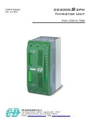
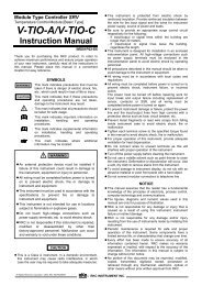
External DimensionsUnit : mm(Terminal cover)91.8Panel cutout9691.8106.192 +0.803092 +0.802596118090.11.0 (Rubber packing)(Panel thickness:1 to 10mm)Rear Terminals· Please use M3 solderless terminal with widthsmaller than 5.9mm.· Unused terminals are not supplied with screws.No.13COMCode 0Code 1FunctionsCode 2Code 3Code 4Code 5Standard141516DI 7DI 8DI 9RESETRUNSTEPRESETRUNSTEP(1)(2)(4)Ptn.No(1)(2)(4)Ptn.NoRESETRUNSTEPRESETRUNSTEPDigital inputs(DI 7 to 11)1718192021COMCT1CT2DI10DI11HOLD (32)(32) Ptn.No. (64)Ptn.No(8)(Optional)CT1,CT2 inputsPtn. SET(8)(16)Open (O)(W)Close (C)HOLDDir/RevHOLDPtn. INC(Optional)Feedbackresistance2223AB24 B (1) (2) (3)Measuringinput(1)Thermocouple(2)RTD(3)Voltage/CurrentNo.1ACLDC2100 - 240V 24V24VN3COM4NODO45 NODO36COM7NODO28 NODO19NO Triac10(1) (2) (3) (4)11NO Triac12(1) (2) (3) (4)FunctionsPower supplyStandardDigital outputs 3, 4(DO 3, 4)• Relay contact outputStandardDigital outputs 1, 2(DO 1, 2)• Relay contact outputOutput 2 (OUT2)(1) Relay output(2) Voltage pulse/Voltage/Current(3) SSR (Triac), (4) Open collectorOutput 1 (OUT1)(1) Relay output(2) Voltage pulse/Voltage/Current(3) SSR (Triac), (4) Open collectorNo.Functions373839404142434445464748COM (-)DO 5DO 6DO 7DO 8COM(-)DO 9DO10DO11DO12(1) (2)(Optional)Digital outputs 5 to 8(DO 5 to 8)• Open collector output(Optional)Digital outputs 9 to12(DO 9 to 12)• Open collector outputOutput 3 (OUT3)(1) Voltage pulse/Voltage/Current(2) Open collectorNo.Functions2526SGSDSGT/R(A)SG COM1T(A)SG COM2 (Optional)Communication 1(1) RS-232CRS-485*1RD T/R(B) T(B)(2) RS-48527(1) (2)(3) RS-422A28R(A)T/R(A)Communication 22930 COMR(B)(3)Code : 0,1T/R(B)Code : 2,3,4,5(Inter-controllers)(Optional)313233DI 1DI 2DI 3(1)(2)(4) PatternNo.WAIT releaseWAIT releaseWAIT release Digital inputs(DI 1 to 6)3435DI 4DI 5(8)(16)WAIT releaseWAIT release36DI 6 Pattern SET WAIT release*1 : To use communication 2 (inter-controller communication).please specify RS-232C or RS-485 for communication 1.SafetyWarning• Before operating this product, read the instruction manual carefully to avoidincorrect operation.• This product is intended for use with industrial machines, test and measuringequipment. It is not designed for use with medical equipment.• If it is possible that an accident may occur as a result of the failure of the product orsome other abnormality, an appropriate independent protection device must beinstalled.Caution for the export tradeAll transactions must comply with laws, regulations, and treaties.Caution : Avoid imitated productsImitation of RKC products are appearing in the marketplace. RKC will not warrant suchproducts nor bear the responsibility for any damage and/or accident caused by their useand urge caution when making your purchase.R(RIKA KOGYO CO.,LTD)HEAD OFFICE : 16-6, KUGAHARA 5 CHOME OHTA-KU TOKYO 146-8515 JAPANPHONE : 03-3751-9799 ( +81 3 3751 9799 )Email : info@rkcinst.co.jpFAX : 03-3751-8585 ( +81 3 3751 8585 )http://www.rkcinst.com/C900PF01EPrinted in Japan : APR.2010OBB8H(P) All Rights Reserved.