Reaction Mechanisms of Charcoal and Coke in the ... - Pyro.co.za
Reaction Mechanisms of Charcoal and Coke in the ... - Pyro.co.za
Reaction Mechanisms of Charcoal and Coke in the ... - Pyro.co.za

Create successful ePaper yourself
Turn your PDF publications into a flip-book with our unique Google optimized e-Paper software.
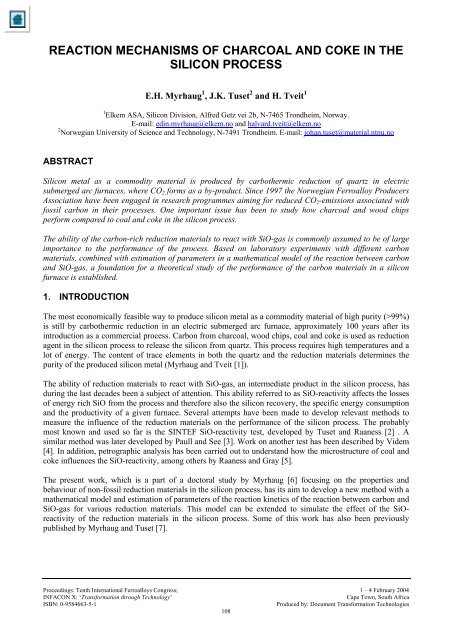
REACTION MECHANISMS OF CHARCOAL AND COKE IN THESILICON PROCESSE.H. Myrhaug 1 , J.K. Tuset 2 <strong>and</strong> H. Tveit 11 Elkem ASA, Sili<strong>co</strong>n Division, Alfred Getz vei 2b, N-7465 Trondheim, Norway.E-mail: ed<strong>in</strong>.myrhaug@elkem.no <strong>and</strong> halvard.tveit@elkem.no2 Norwegian University <strong>of</strong> Science <strong>and</strong> Technology, N-7491 Trondheim. E-mail: johan.tuset@material.ntnu.noABSTRACTSili<strong>co</strong>n metal as a <strong>co</strong>mmodity material is produced by carbo<strong>the</strong>rmic reduction <strong>of</strong> quartz <strong>in</strong> electricsubmerged arc furnaces, where CO 2 forms as a by-product. S<strong>in</strong>ce 1997 <strong>the</strong> Norwegian Ferroalloy ProducersAssociation have been engaged <strong>in</strong> research programmes aim<strong>in</strong>g for reduced CO 2 -emissions associated withfossil carbon <strong>in</strong> <strong>the</strong>ir processes. One important issue has been to study how char<strong>co</strong>al <strong>and</strong> wood chipsperform <strong>co</strong>mpared to <strong>co</strong>al <strong>and</strong> <strong>co</strong>ke <strong>in</strong> <strong>the</strong> sili<strong>co</strong>n process.The ability <strong>of</strong> <strong>the</strong> carbon-rich reduction materials to react with SiO-gas is <strong>co</strong>mmonly assumed to be <strong>of</strong> largeimportance to <strong>the</strong> performance <strong>of</strong> <strong>the</strong> process. Based on laboratory experiments with different carbonmaterials, <strong>co</strong>mb<strong>in</strong>ed with estimation <strong>of</strong> parameters <strong>in</strong> a ma<strong>the</strong>matical model <strong>of</strong> <strong>the</strong> reaction between carbon<strong>and</strong> SiO-gas, a foundation for a <strong>the</strong>oretical study <strong>of</strong> <strong>the</strong> performance <strong>of</strong> <strong>the</strong> carbon materials <strong>in</strong> a sili<strong>co</strong>nfurnace is established.1. INTRODUCTIONThe most e<strong>co</strong>nomically feasible way to produce sili<strong>co</strong>n metal as a <strong>co</strong>mmodity material <strong>of</strong> high purity (>99%)is still by carbo<strong>the</strong>rmic reduction <strong>in</strong> an electric submerged arc furnace, approximately 100 years after its<strong>in</strong>troduction as a <strong>co</strong>mmercial process. Carbon from char<strong>co</strong>al, wood chips, <strong>co</strong>al <strong>and</strong> <strong>co</strong>ke is used as reductionagent <strong>in</strong> <strong>the</strong> sili<strong>co</strong>n process to release <strong>the</strong> sili<strong>co</strong>n from quartz. This process requires high temperatures <strong>and</strong> alot <strong>of</strong> energy. The <strong>co</strong>ntent <strong>of</strong> trace elements <strong>in</strong> both <strong>the</strong> quartz <strong>and</strong> <strong>the</strong> reduction materials determ<strong>in</strong>es <strong>the</strong>purity <strong>of</strong> <strong>the</strong> produced sili<strong>co</strong>n metal (Myrhaug <strong>and</strong> Tveit [1]).The ability <strong>of</strong> reduction materials to react with SiO-gas, an <strong>in</strong>termediate product <strong>in</strong> <strong>the</strong> sili<strong>co</strong>n process, hasdur<strong>in</strong>g <strong>the</strong> last decades been a subject <strong>of</strong> attention. This ability referred to as SiO-reactivity affects <strong>the</strong> losses<strong>of</strong> energy rich SiO from <strong>the</strong> process <strong>and</strong> <strong>the</strong>refore also <strong>the</strong> sili<strong>co</strong>n re<strong>co</strong>very, <strong>the</strong> specific energy <strong>co</strong>nsumption<strong>and</strong> <strong>the</strong> productivity <strong>of</strong> a given furnace. Several attempts have been made to develop relevant methods tomeasure <strong>the</strong> <strong>in</strong>fluence <strong>of</strong> <strong>the</strong> reduction materials on <strong>the</strong> performance <strong>of</strong> <strong>the</strong> sili<strong>co</strong>n process. The probablymost known <strong>and</strong> used so far is <strong>the</strong> SINTEF SiO-reactivity test, developed by Tuset <strong>and</strong> Raaness [2] . Asimilar method was later developed by Paull <strong>and</strong> See [3]. Work on ano<strong>the</strong>r test has been described by Videm[4]. In addition, petrographic analysis has been carried out to underst<strong>and</strong> how <strong>the</strong> microstructure <strong>of</strong> <strong>co</strong>al <strong>and</strong><strong>co</strong>ke <strong>in</strong>fluences <strong>the</strong> SiO-reactivity, among o<strong>the</strong>rs by Raaness <strong>and</strong> Gray [5].The present work, which is a part <strong>of</strong> a doctoral study by Myrhaug [6] focus<strong>in</strong>g on <strong>the</strong> properties <strong>and</strong>behaviour <strong>of</strong> non-fossil reduction materials <strong>in</strong> <strong>the</strong> sili<strong>co</strong>n process, has its aim to develop a new method with ama<strong>the</strong>matical model <strong>and</strong> estimation <strong>of</strong> parameters <strong>of</strong> <strong>the</strong> reaction k<strong>in</strong>etics <strong>of</strong> <strong>the</strong> reaction between carbon <strong>and</strong>SiO-gas for various reduction materials. This model can be extended to simulate <strong>the</strong> effect <strong>of</strong> <strong>the</strong> SiOreactivity<strong>of</strong> <strong>the</strong> reduction materials <strong>in</strong> <strong>the</strong> sili<strong>co</strong>n process. Some <strong>of</strong> this work has also been previouslypublished by Myrhaug <strong>and</strong> Tuset [7].Proceed<strong>in</strong>gs: Tenth International Ferroalloys Congress; 1 – 4 February 2004INFACON X: ‘Transformation through Technology’Cape Town, South AfricaISBN: 0-9584663-5-1Produced by: Document Transformation Technologies
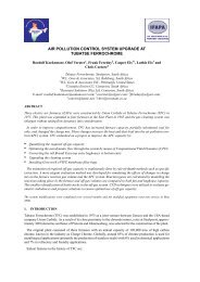
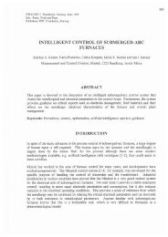
2. THE SILICON PROCESSThe pr<strong>in</strong>cipal parts <strong>of</strong> a modern sili<strong>co</strong>n plant are shown <strong>in</strong> Figure 1. The <strong>co</strong>re <strong>of</strong> this plant is <strong>the</strong> electricsubmerged arc furnace. It <strong>co</strong>nsists <strong>of</strong> a furnace body with <strong>the</strong> shape <strong>of</strong> a shallow crucible, which is filled upto its rim with raw materials charged by gravity through a system <strong>of</strong> silos <strong>and</strong> tubes as shown. The energyneeded for <strong>the</strong> smelt<strong>in</strong>g is delivered as 3-phase alternat<strong>in</strong>g current through three carbon electrodes positionedvertically <strong>and</strong> submerged deep <strong>in</strong>to <strong>the</strong> charge mixture. 90-95% <strong>of</strong> <strong>the</strong> supplied energy is dissipated as heat<strong>in</strong> gas-filled cavities surround<strong>in</strong>g <strong>the</strong> tip <strong>of</strong> <strong>the</strong> electrodes.The sili<strong>co</strong>n form<strong>in</strong>g reactions, which requires temperatures <strong>in</strong> excess <strong>of</strong> 1800ºC, take place <strong>in</strong> <strong>the</strong>se <strong>in</strong>nerzones <strong>of</strong> <strong>the</strong> furnace. The produced sili<strong>co</strong>n metal is tapped from <strong>the</strong> furnace through tapp<strong>in</strong>g holes at <strong>the</strong><strong>co</strong>nnection between <strong>the</strong> side <strong>and</strong> bottom <strong>of</strong> <strong>the</strong> furnace body. The gas leav<strong>in</strong>g <strong>the</strong> <strong>in</strong>ner zones carries mostlyCO- <strong>and</strong> SiO-gas. Most <strong>of</strong> <strong>the</strong> latter is re<strong>co</strong>vered <strong>in</strong> <strong>the</strong> outer (upper) <strong>and</strong> <strong>co</strong>lder zones <strong>of</strong> <strong>the</strong> charge, ei<strong>the</strong>rby reaction with C <strong>in</strong> <strong>the</strong> charged reduction materials to SiC or by <strong>co</strong>ndensation to a sticky mass <strong>of</strong> SiO 2 <strong>and</strong>Si(l). These materials are transported down to <strong>the</strong> cavity <strong>in</strong> <strong>the</strong> <strong>in</strong>ner zones, while <strong>the</strong> last fraction <strong>of</strong> <strong>the</strong> SiOgasis lost toge<strong>the</strong>r with <strong>the</strong> CO-gas above <strong>the</strong> top <strong>of</strong> <strong>the</strong> charge. This gas mixture mixes with air from <strong>the</strong>surround<strong>in</strong>gs <strong>and</strong> burns under formation <strong>of</strong> CO 2 <strong>and</strong> silica fumes. The latter, which is mostly amorphousSiO 2 , may be re<strong>co</strong>vered <strong>in</strong> <strong>of</strong>f-gas filters, while <strong>the</strong> CO 2 enters <strong>the</strong> atmosphere.Figure 1. Pr<strong>in</strong>cipal parts <strong>of</strong> a modern sili<strong>co</strong>n plant. After Schei, Tuset <strong>and</strong> Tveit.3. REACTION BETWEEN THE REDUCTION MATERIALS AND SIO-GASWhen <strong>co</strong>als are exposed to high temperatures at <strong>the</strong> top <strong>of</strong> <strong>the</strong> sili<strong>co</strong>n furnace, <strong>the</strong>y are devolatilized <strong>and</strong><strong>co</strong>nverted <strong>in</strong>to char or <strong>co</strong>ke before start<strong>in</strong>g to react with <strong>the</strong> SiO-gas. The wood chips will undergo a similar<strong>co</strong>nversion to char<strong>co</strong>al. Due to this, it is assumed <strong>in</strong> <strong>the</strong> fur<strong>the</strong>r discussions that <strong>the</strong> SiO-gas reacts with <strong>co</strong>keor char<strong>co</strong>al.Tuset <strong>and</strong> Raaness [2] found dur<strong>in</strong>g <strong>the</strong>ir work on SiO-reactivity that this property to a large extent is relatedto <strong>the</strong> effective diffusivity <strong>of</strong> SiO-gas <strong>in</strong> <strong>the</strong> pores <strong>of</strong> <strong>the</strong> reduction materials. Raaness <strong>and</strong> Gray [5] have<strong>in</strong>vestigated <strong>the</strong> SiO-reactivity <strong>and</strong> petrography <strong>of</strong> several chars/<strong>co</strong>kes as well as <strong>the</strong> petrography <strong>of</strong> <strong>the</strong> <strong>co</strong>alsfrom which <strong>the</strong>se samples were derived. They described a relation between <strong>the</strong> microstructure <strong>and</strong> carbonforms <strong>of</strong> several chars/<strong>co</strong>kes <strong>and</strong> <strong>the</strong> SiO-reactivity. Based on some assumptions <strong>the</strong>y showed that <strong>the</strong>re is agood <strong>co</strong>rrelation between <strong>the</strong> SiO-reactivity <strong>of</strong> <strong>the</strong> chars/<strong>co</strong>kes <strong>and</strong> <strong>the</strong> rank <strong>of</strong> <strong>the</strong> <strong>co</strong>als <strong>the</strong>y are derivedfrom. In addition Raaness, Kolbe<strong>in</strong>sen <strong>and</strong> Byberg [9] established a model for prediction <strong>of</strong> <strong>co</strong>al properties<strong>in</strong> <strong>the</strong> sili<strong>co</strong>n or ferrosili<strong>co</strong>n production based on multivariate analysis on SiO-reactivity <strong>of</strong> <strong>co</strong>ke <strong>and</strong>petrographic properties <strong>of</strong> <strong>the</strong> <strong>co</strong>als <strong>the</strong>y were derived from.
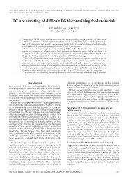
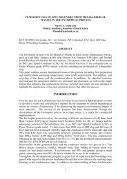
They found that such a model for predict<strong>in</strong>g SiO-reactivity should <strong>in</strong>clude <strong>the</strong> follow<strong>in</strong>g properties <strong>of</strong> <strong>the</strong><strong>co</strong>als:• Distribution <strong>and</strong> amounts <strong>of</strong> vitr<strong>in</strong>ite types <strong>in</strong> <strong>the</strong> <strong>co</strong>als or amount <strong>of</strong> carbon form precursors• Reflectance• Amount <strong>and</strong> distribution <strong>of</strong> reactive macerals• Amount <strong>and</strong> distribution <strong>of</strong> <strong>in</strong>ert maceralsFigure 2 shows <strong>the</strong> microstructure <strong>of</strong> samples <strong>of</strong> <strong>co</strong>ke <strong>and</strong> char<strong>co</strong>al, respectively, as obta<strong>in</strong>ed us<strong>in</strong>g amicroprobe <strong>of</strong> type JXA-8900 M WD/ED Comb<strong>in</strong>ed. The pictures show clearly <strong>the</strong> porous structure <strong>of</strong> <strong>the</strong>samples. The <strong>co</strong>ke displays thicker walls <strong>and</strong> more <strong>in</strong>homogeneous structure <strong>and</strong> pore sizes than <strong>the</strong>char<strong>co</strong>al, which has very th<strong>in</strong> walls. The walls <strong>in</strong> <strong>the</strong> char<strong>co</strong>al can be identified as <strong>the</strong> cell walls <strong>in</strong> <strong>the</strong> woodit was derived from. In both materials <strong>the</strong> walls <strong>in</strong> <strong>the</strong> solid matrix <strong>co</strong>nsists <strong>of</strong> amorphous C.The reaction between <strong>the</strong> SiO-gas <strong>and</strong> <strong>the</strong> C <strong>in</strong> <strong>the</strong> reduction materials goes as follows:SiO(g) + 2 C(s) = SiC(s) + CO(g) (1)(a)(b)Figure 2. Microprobe pictures show<strong>in</strong>g microstructure <strong>of</strong> samples <strong>of</strong> (a) <strong>Coke</strong> B <strong>and</strong> (b) <strong>Char<strong>co</strong>al</strong> A(refer to Tables 1 <strong>and</strong> 2).(a)Figure 3. Microprobe pictures <strong>of</strong> porous carbon spheres <strong>of</strong> (a) <strong>Coke</strong> B <strong>and</strong> (b) <strong>Char<strong>co</strong>al</strong> A (refer to Tables 1<strong>and</strong> 2) display<strong>in</strong>g topochemical <strong>co</strong>nversion from carbon particle to SiC. Both spheres are about 50 %<strong>co</strong>nverted.(b)
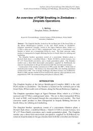
In <strong>the</strong> equilibrium gas <strong>co</strong>mposition established <strong>in</strong> a charge mixture <strong>of</strong> SiO 2 /C at 1 atm. pressure, this reactionis shifted to <strong>the</strong> right at temperatures above approximately 1500 °C (Schei et.al. [8]). For a reaction <strong>of</strong> <strong>the</strong>above type <strong>the</strong> <strong>co</strong>nversion is assumed to progress from <strong>the</strong> outer surface to <strong>the</strong> <strong>in</strong>terior <strong>of</strong> a particle, form<strong>in</strong>ga product layer around <strong>the</strong> unreacted central part. The reaction zone may have a diffuse extension <strong>in</strong> <strong>the</strong>radial direction as can be seen from <strong>the</strong> microprobe pictures displayed <strong>in</strong> Figure 3, where <strong>the</strong> cross section <strong>of</strong>two partially <strong>co</strong>nverted carbon spheres are shown.4. KINETIC MODEL OF REACTION BETWEEN CARBON AND SIO-GASAc<strong>co</strong>rd<strong>in</strong>g to Sohn [10] <strong>the</strong> most important group <strong>of</strong> reactions <strong>in</strong> metallurgical <strong>and</strong> materials process<strong>in</strong>goperations <strong>co</strong>nsists <strong>of</strong> those <strong>in</strong> which a solid reacts with a fluid to produce a <strong>co</strong>herent layer <strong>of</strong> porousproducts. Such reactions may <strong>in</strong> general be expressed by:a A(g) + b B(s) = c C(g) + d D(s) (2)4.1 Application <strong>of</strong> <strong>the</strong> shr<strong>in</strong>k<strong>in</strong>g <strong>co</strong>re modelThe earliest model <strong>of</strong> gas-solid reactions <strong>in</strong> this <strong>co</strong>ntext is <strong>the</strong> shr<strong>in</strong>k<strong>in</strong>g <strong>co</strong>re model. Among <strong>the</strong> earliest <strong>and</strong>most <strong>of</strong>ten mentioned <strong>co</strong>ntributors to this are Yagi <strong>and</strong> Kunii [11]. The shr<strong>in</strong>k<strong>in</strong>g <strong>co</strong>re model is based onassumptions <strong>of</strong> an <strong>in</strong>itially nonporous reactant <strong>and</strong> progress <strong>of</strong> <strong>the</strong> reaction <strong>in</strong> a topochemical manner from<strong>the</strong> outer surface <strong>of</strong> <strong>the</strong> solid towards <strong>the</strong> centre. The chemical reaction forms a product (or ash) layer around<strong>the</strong> shr<strong>in</strong>k<strong>in</strong>g unreacted <strong>co</strong>re <strong>of</strong> <strong>the</strong> solid <strong>and</strong> takes place at a sharp boundary between <strong>the</strong> two zones. Thismodel is illustrated for <strong>co</strong>nversion <strong>of</strong> a carbonaceous particle to SiC <strong>in</strong> Figure 4 <strong>and</strong> have been extensivelystudied <strong>and</strong> applied to a wide range <strong>of</strong> reactions.Bulk gasSiOCOCSiCR PR CTh<strong>in</strong> reactionzoneGas filmFigure 4. Shr<strong>in</strong>k<strong>in</strong>g <strong>co</strong>re model for carbonaceous sphere.In <strong>the</strong> doctoral study <strong>of</strong> Myrhaug [6] various models for both nonporous <strong>and</strong> porous solids were used <strong>in</strong>parameter estimation based on experimental data ga<strong>the</strong>red from <strong>the</strong>rmogravimetric experiments. Afterwards,<strong>the</strong> models with <strong>the</strong> found parameters were tested aga<strong>in</strong>st results from both <strong>the</strong> <strong>the</strong>rmogravimetricexperiments <strong>and</strong> <strong>the</strong> SINTEF SiO-reactivity test. The results from <strong>the</strong> estimation <strong>and</strong> test<strong>in</strong>g showed that <strong>the</strong>shr<strong>in</strong>k<strong>in</strong>g <strong>co</strong>re model gave <strong>the</strong> best prediction <strong>of</strong> <strong>co</strong>nversion <strong>of</strong> particles versus time for both <strong>the</strong><strong>the</strong>rmogravimetric experiments <strong>and</strong> <strong>the</strong> SINTEF SiO-reactivity test, with an overall range <strong>of</strong> particlediameters from approximately 5 up to 25 mm.When us<strong>in</strong>g <strong>the</strong> shr<strong>in</strong>k<strong>in</strong>g <strong>co</strong>re model for react<strong>in</strong>g carbonaceous particles <strong>in</strong> an atmosphere with SiO-gassome assumptions are made:• The chemical reaction is go<strong>in</strong>g on <strong>in</strong> an <strong>in</strong>f<strong>in</strong>itely th<strong>in</strong> layer on <strong>the</strong> unreacted <strong>co</strong>re with a radius R C <strong>in</strong> asphere <strong>of</strong> radius R P , as showed <strong>in</strong> Figure 4.• <strong>Reaction</strong> (1) at <strong>the</strong> surface <strong>of</strong> <strong>the</strong> unreacted <strong>co</strong>re <strong>of</strong> C is <strong>of</strong> first order.• The <strong>co</strong>ncentration pr<strong>of</strong>iles <strong>of</strong> gases with<strong>in</strong> <strong>the</strong> product layer at any <strong>in</strong>stant time are assumed to be <strong>the</strong>steady-state pr<strong>of</strong>iles over <strong>the</strong> distance (R P -R C ) with equimolar <strong>co</strong>unterdiffusion <strong>and</strong> no accumulation <strong>of</strong>gaseous species with<strong>in</strong> <strong>the</strong> particle (pseudo-steady-state approximation).• Particle volume rema<strong>in</strong>s unchanged dur<strong>in</strong>g <strong>co</strong>nversion.• There are no temperature gradients with<strong>in</strong> <strong>the</strong> react<strong>in</strong>g particle or between <strong>the</strong> particle <strong>and</strong> <strong>the</strong>surround<strong>in</strong>g gas.
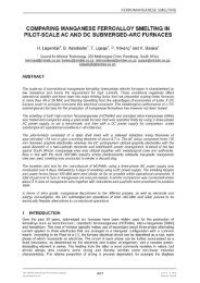
The overall rate <strong>of</strong> <strong>co</strong>nversion <strong>of</strong> <strong>the</strong> particle is determ<strong>in</strong>ed by both external mass transfer through <strong>the</strong> gasfilm at <strong>the</strong> surface <strong>of</strong> <strong>the</strong> sphere, diffusion through <strong>the</strong> pore structure <strong>in</strong> <strong>the</strong> product layer <strong>and</strong> chemicalreaction rate at <strong>the</strong> surface <strong>of</strong> <strong>the</strong> shr<strong>in</strong>k<strong>in</strong>g unreacted <strong>co</strong>re. The relation between degree <strong>of</strong> <strong>co</strong>nversion <strong>and</strong>time <strong>in</strong><strong>co</strong>rporat<strong>in</strong>g <strong>the</strong>se effects for a particle with a shr<strong>in</strong>k<strong>in</strong>g unreacted <strong>co</strong>re is described by many authors,among o<strong>the</strong>rs Sohn [10], Yagi <strong>and</strong> Kunii [11], Szekely et. al. [12] <strong>and</strong> Levenspiel [13]. In this work,spherical particles are assumed, <strong>and</strong> <strong>the</strong> follow<strong>in</strong>g expression for time t versus <strong>the</strong> overall degree <strong>of</strong><strong>co</strong>nversion X is deduced from Sohn [10] <strong>and</strong> Szekely et. al. [12]:t( X)=⎛1 21 ⎛ ⎞ 1 R 1 1 1 13 p ⎛ ⎞⎛ ⎞ ⎛ ⎞ ⎞3αCRC p C1 −(1 − X) + 1+ 3−3(1 − X) − 2X + 1+X⎜k ⎜ ⎟ ⎜ ⎟CDE 6 K ⎜ ⎟ ⎜ ⎟EhD 3 K ⎟⎝ ⎝ ⎠ ⎝ ⎠⎝ ⎠ ⎝ E ⎠ ⎠⎛ CCO,B ⎞b⎜CSiO,B− ⎟⎝ KE⎠(3)In this equation, k C is <strong>the</strong> chemical reaction rate <strong>co</strong>nstant <strong>in</strong> m/s for <strong>Reaction</strong> (1) <strong>and</strong> D E is <strong>the</strong> effectivediffusivity <strong>of</strong> <strong>the</strong> gas <strong>in</strong> <strong>the</strong> product layer <strong>of</strong> <strong>the</strong> sphere <strong>in</strong> m 2 /s. These parameters are assumed to be differentfor different k<strong>in</strong>ds <strong>of</strong> carbonaceous materials. h D is <strong>the</strong> mass transfer <strong>co</strong>efficient from <strong>the</strong> bulk gas to <strong>the</strong>surface <strong>of</strong> particle <strong>in</strong> m 2 /s, K E is <strong>the</strong> equilibrium <strong>co</strong>nstant for <strong>Reaction</strong> (1), R P is <strong>the</strong> radius <strong>of</strong> <strong>the</strong> sphere <strong>and</strong> bis <strong>the</strong> number <strong>of</strong> moles <strong>of</strong> C(s) per mole SiO(g) <strong>in</strong> <strong>Reaction</strong> (1). C SiO,B <strong>and</strong> C CO,B are <strong>co</strong>ncentrations <strong>of</strong> SiO(g)<strong>and</strong> CO(g) <strong>in</strong> <strong>the</strong> bulk gas around <strong>the</strong> particle. α C <strong>and</strong> C C are volume fraction <strong>and</strong> molar density <strong>of</strong> solid C(s)<strong>in</strong> <strong>the</strong> particle, respectively. The overall degree <strong>of</strong> <strong>co</strong>nversion X <strong>of</strong> C(s) to SiC(s) <strong>in</strong> <strong>the</strong> particle (0≤X≤1) maybe calculated from <strong>the</strong> radii R P <strong>and</strong> R C with <strong>the</strong> formula:XR= 1− (4)R3C3P<strong>Reaction</strong> (1) results <strong>in</strong> a weight <strong>in</strong>crease for <strong>the</strong> particle, <strong>and</strong> if <strong>the</strong> weight is re<strong>co</strong>rded dur<strong>in</strong>g <strong>co</strong>nversion, for<strong>in</strong>stance as a part <strong>of</strong> an experiment, <strong>the</strong> degree <strong>of</strong> <strong>co</strong>nversion may be calculated from measurements with <strong>the</strong>formula:X=wmFC0 P0( mP- mP0)(40.10 - 2⋅12.01) /(2⋅12.01)(5)where m P is <strong>the</strong> actual weight, m P0 is <strong>the</strong> <strong>in</strong>itial weight <strong>of</strong> <strong>the</strong> particle <strong>and</strong> w FC0 is <strong>the</strong> mass fraction <strong>of</strong> fixedcarbon. m P , m P0 <strong>and</strong> w FC0 are all re<strong>co</strong>rded or calculated without <strong>co</strong>ntent <strong>of</strong> volatile matter <strong>in</strong> <strong>the</strong> particle.12.01 <strong>and</strong> 40.10 are molar weights <strong>of</strong> C(s) <strong>and</strong> SiC(s), respectively. The formula depicts that <strong>the</strong> 2 moles <strong>of</strong>C(s) react to 1 mole <strong>of</strong> SiC(s). The overall rate <strong>of</strong> <strong>co</strong>nversion can be derived from Equation (3):dX( X ) =dtb ⎛ CCO,B ⎞⎜CSiO,B− ⎟αCCCRP ⎝ KE⎠2 11 ⎛1 − ⎞ 1 R 1 1 1 13 p ⎛ ⎞⎛ − ⎞ ⎛ ⎞3(1 − X) + 1 + 2(1 − X) − 2 + 1+k ⎜ C3 ⎟ ⎜ ⎟ DE 6 K ⎜ ⎟ ⎜ ⎟⎝ ⎠ ⎝ E ⎠⎝ ⎠ hD 3⎝ KE⎠(6)5. THERMOGRAVIMETRIC EXPERIMENTS AND ESTIMATION5.1 Equipment <strong>and</strong> proceduresLaboratory experiments on s<strong>in</strong>gle spheres <strong>of</strong> carbon us<strong>in</strong>g a <strong>the</strong>rmogravimetric method are carried out <strong>in</strong> a<strong>co</strong>ntrolled atmosphere <strong>co</strong>nta<strong>in</strong><strong>in</strong>g known <strong>co</strong>ncentrations <strong>of</strong> SiO, CO <strong>and</strong> Ar at a temperature <strong>of</strong> 1650°C, <strong>and</strong>with a chosen flow rate <strong>of</strong> <strong>the</strong> gas. By re<strong>co</strong>rd<strong>in</strong>g <strong>the</strong> weight <strong>of</strong> <strong>the</strong> sphere <strong>co</strong>nt<strong>in</strong>uously dur<strong>in</strong>g <strong>the</strong>experiments, <strong>and</strong> us<strong>in</strong>g <strong>the</strong> fact that <strong>co</strong>nversion from C to SiC results <strong>in</strong> a certa<strong>in</strong> <strong>in</strong>crease <strong>of</strong> weight, it ispossible to estimate k C <strong>and</strong> D E by curve fitt<strong>in</strong>g (l<strong>in</strong>ear regression). A sketch <strong>of</strong> <strong>the</strong> experimental equipment isgiven <strong>in</strong> Figure 5, but a more detailed description is found <strong>in</strong> <strong>the</strong> <strong>the</strong>sis by Myrhaug [6]. The diameters <strong>of</strong><strong>the</strong> spheres used <strong>in</strong> <strong>the</strong> experiments were <strong>in</strong> <strong>the</strong> range 8-25 mm. Some precautions have been made <strong>in</strong> orderto prevent unwanted chemical reactions with surround<strong>in</strong>g parts <strong>in</strong> <strong>the</strong> reaction chamber.
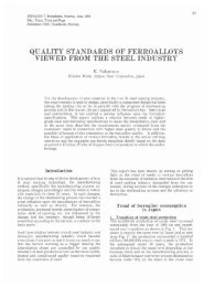
180016140012 00Temp0[C] 1000008060040 002000Temp Vekt0[°C] [ ]09:4 10:0 10:1 10:3 10:4 11:0 11:1 11:3 11:4 12:0 12:1 12:3 12:4 13:0 13:1 13:3 13:4 14:0 14:14:314:4500 000 500 000 50000500 000 500 000 500 000 50000500 000 500 000 50000500Tid2.42.2.32. 22.1 Vekt[g]1.01.91. 81.761.5Typical time series for weight <strong>and</strong> temperature from one experiment are given <strong>in</strong> Figure 6. About two hoursare spent <strong>in</strong> order to reach 1650°C, <strong>and</strong> at approximately 1500°C <strong>the</strong> weight starts to <strong>in</strong>crease due toavailable SiO-gas supplied from a separate reaction chamber which is heated at nearly <strong>the</strong> same rate as <strong>the</strong>spherical sample itself. This chamber is filled with an agglomerate <strong>of</strong> SiO 2 <strong>and</strong> SiC <strong>in</strong> order to produce SiO<strong>and</strong>CO-gas ac<strong>co</strong>rd<strong>in</strong>g to <strong>the</strong> reaction:2SiO 2 + SiC = 3SiO(g) + CO(g) (7)Argon is used as carrier gas at a <strong>co</strong>nstant flow rate upwards through <strong>the</strong> reaction chamber. The SiO-source iskept at a slightly lower temperature than <strong>the</strong> carbon sphere <strong>in</strong> order to ensure that an <strong>in</strong>crease <strong>in</strong> weight <strong>of</strong> <strong>the</strong>sphere is caused by <strong>Reaction</strong> (1) <strong>and</strong> not by <strong>co</strong>ndensation <strong>of</strong> SiO-gas.Signal<strong>in</strong>putBalanceHeleComputer w/data aquisitionTemperature<strong>co</strong>ntrollerTransformerCSiO(g)FurnaceFigure 5. Ma<strong>in</strong> pr<strong>in</strong>ciples <strong>of</strong> equipment used dur<strong>in</strong>g experiments.Termo<strong>co</strong>upleData from experimentTemperatureWeightTemperature[C]18001600140012001000800600400200009:45:0010:00:0010:15:0010:30:0010:45:0011:00:0011:15:0011:30:0011:45:0012:00:0012:15:0012:30:00Time12:45:0013:00:0013:15:0013:30:0013:45:0014:00:0014:15:0014:30:0014:45:00Figure 6. Data from one experiment show<strong>in</strong>g <strong>the</strong> temperature <strong>and</strong> weight <strong>of</strong> a carbon sphere.5.2 Estimation <strong>of</strong> k<strong>in</strong>etic parametersThe k<strong>in</strong>etic parameters D E <strong>and</strong> k C <strong>in</strong> <strong>the</strong> shr<strong>in</strong>k<strong>in</strong>g <strong>co</strong>re model <strong>in</strong> Equation (3) are estimated from <strong>the</strong>re<strong>co</strong>rded time series for weight by calculat<strong>in</strong>g <strong>the</strong> degree <strong>of</strong> <strong>co</strong>nversion from Equation (5) <strong>and</strong> fitt<strong>in</strong>g <strong>the</strong>shr<strong>in</strong>k<strong>in</strong>g <strong>co</strong>re model to <strong>the</strong> experimental data for time versus degree <strong>of</strong> <strong>co</strong>nversion. The model is fitted to<strong>the</strong> data by us<strong>in</strong>g <strong>the</strong> method <strong>of</strong> least squares as described by among o<strong>the</strong>rs Kreyzig [14].Data from three or more experiments with spheres from <strong>the</strong> same material, but with different radii, are<strong>co</strong>mb<strong>in</strong>ed <strong>and</strong> used as basis for <strong>the</strong> estimation <strong>of</strong> <strong>the</strong> k<strong>in</strong>etic parameters for that particular material. The<strong>co</strong>mb<strong>in</strong>ation <strong>of</strong> data <strong>in</strong> this way is done to ensure physically realistic or valid estimates <strong>of</strong> D E <strong>and</strong> k C for <strong>the</strong>whole range <strong>of</strong> R P <strong>in</strong>vestigated for each k<strong>in</strong>d <strong>of</strong> carbonaceous material. In addition, some <strong>co</strong>rrections weremade to <strong>the</strong> data <strong>and</strong> <strong>the</strong> shr<strong>in</strong>k<strong>in</strong>g <strong>co</strong>re model to improve <strong>the</strong> quality <strong>of</strong> <strong>the</strong> estimated parameters. Fur<strong>the</strong>rdetails about this <strong>and</strong> <strong>the</strong> experimental techniques applied are described <strong>in</strong> <strong>the</strong> <strong>the</strong>sis <strong>of</strong> Myrhaug [6].2.42.32.22.12.01.91.81.71.61.5Weight[g]
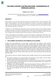
(a)(b)(c)Figure 7. Example <strong>of</strong> data from <strong>in</strong>dividual experiments <strong>and</strong> results from simulations with shr<strong>in</strong>k<strong>in</strong>g <strong>co</strong>remodel for some carbonaceous materials with diameters as given. (a) <strong>Char<strong>co</strong>al</strong> A, (b) <strong>Char<strong>co</strong>al</strong> B,(c) <strong>Coke</strong> A <strong>and</strong> (d) <strong>Coke</strong> B.6. MODEL CALCULATION OF PACKED BEDS6.1 Model descriptionThe k<strong>in</strong>etic parameters D E <strong>and</strong> k C , when known, can be used to predict how efficient a given reductionmaterial can be <strong>in</strong> re<strong>co</strong>ver<strong>in</strong>g <strong>the</strong> SiO-gas ac<strong>co</strong>rd<strong>in</strong>g to <strong>Reaction</strong> (1) <strong>in</strong> a packed bed. In <strong>the</strong> charge mixture <strong>of</strong>a sili<strong>co</strong>n furnace <strong>the</strong> particles <strong>of</strong> both reduction materials <strong>and</strong> quartz form a packed bed. Formulas for gassolidreactions <strong>in</strong> packed bed <strong>co</strong>mb<strong>in</strong>ed with <strong>the</strong> shr<strong>in</strong>k<strong>in</strong>g <strong>co</strong>re model for <strong>in</strong>dividual spherical particles aredescribed among o<strong>the</strong>rs by Szekely et. al. [12]. The parameters found for <strong>the</strong> shr<strong>in</strong>k<strong>in</strong>g <strong>co</strong>re model for s<strong>in</strong>glespheres can be used directly <strong>in</strong> <strong>the</strong>se formulas. This means that <strong>the</strong> results from experiments on s<strong>in</strong>glespheres can be used to model <strong>the</strong> behaviour <strong>of</strong> various reduction materials with respect to <strong>the</strong>ir reaction withSiO-gas <strong>in</strong> <strong>the</strong> charge mixture <strong>of</strong> a sili<strong>co</strong>n furnace. Also SINTEF's SiO-reactivity test, where SiO-gas flowsthrough a bed <strong>of</strong> nearly spherical <strong>and</strong> equally sized carbonaceous particles that are <strong>co</strong>nverted to SiC, can bemodelled <strong>in</strong> <strong>the</strong> same way. This gives a good possibility to <strong>co</strong>mpare results with this test. Both <strong>the</strong>se casesare illustrated <strong>in</strong> Figure 8 (a) <strong>and</strong> (b).The model <strong>of</strong> a packed bed is made up <strong>of</strong> mass balances <strong>of</strong> carbon <strong>and</strong> SiO- <strong>and</strong> CO-gas for a number <strong>of</strong><strong>co</strong>ntrol volumes as generally described by Patankar [16]. The model <strong>in</strong>cludes <strong>the</strong> possibility <strong>of</strong> us<strong>in</strong>g twocarbon types <strong>of</strong> different diameters <strong>and</strong> properties <strong>in</strong> order to <strong>in</strong>vestigate <strong>co</strong>mb<strong>in</strong>ations <strong>of</strong> reductionmaterials, but is iso<strong>the</strong>rmal <strong>and</strong> at present stage restricted to 1650°C because <strong>the</strong> reaction k<strong>in</strong>etic parametersare based on data from experiments carried out at this temperature. Figure 8(c) gives a schematic overview<strong>of</strong> <strong>the</strong> <strong>co</strong>ntrol volumes <strong>and</strong> <strong>the</strong> ma<strong>in</strong> variables <strong>in</strong>volved. In present formulation, <strong>the</strong> mass <strong>and</strong> degree <strong>of</strong><strong>co</strong>nversion <strong>of</strong> carbon is evaluated <strong>in</strong> <strong>the</strong> middle <strong>of</strong> <strong>the</strong> <strong>co</strong>ntrol volumes assum<strong>in</strong>g to be an average for <strong>the</strong>whole <strong>co</strong>ntrol volume. Plug flow <strong>of</strong> both solids <strong>and</strong> gases is assumed. Upw<strong>in</strong>d-difference scheme (Patankar[16]) is used to h<strong>and</strong>le <strong>the</strong> flows <strong>of</strong> mass at <strong>the</strong> boundaries <strong>of</strong> <strong>the</strong> <strong>co</strong>ntrol volumes, where also <strong>the</strong> gas<strong>co</strong>ncentrations (alternatively pressures) are evaluated.(d)
X Ci,N+1CSiO(g)CSiO(g)F Ci,N+1F Ci,NC SiO,N+1C SiO,NC SiO,N-1X Ci,NX Ci,N-1C CO,N+1F SiO,N+1F CO,N+1C CO,NF SiO,NF CO,NC CO,N-1(a)(b)Figure 8. (a) The packed bed <strong>in</strong> <strong>the</strong> SINTEF SiO-reactivity test, (b) <strong>the</strong> packed bed <strong>in</strong> <strong>the</strong> sili<strong>co</strong>n furnace, <strong>and</strong>(c) schematic overview <strong>of</strong> <strong>the</strong> model <strong>of</strong> <strong>the</strong> packed bed with <strong>co</strong>ntrol volumes <strong>and</strong> ma<strong>in</strong> variables.The mass balance for <strong>the</strong> two types <strong>of</strong> carbon <strong>in</strong> one <strong>co</strong>ntrol volume is given by(c)dmCi,Ndt= r + F − F(8)Ci, N Ci, N + 1 Ci,Nwhere N is <strong>the</strong> number <strong>of</strong> <strong>the</strong> actual <strong>co</strong>ntrol volume, m Ci,N is <strong>the</strong> mass <strong>of</strong> unreacted carbon type i <strong>in</strong> that<strong>co</strong>ntrol volume, r Ci,N is <strong>the</strong> reaction rate <strong>of</strong> carbon type i <strong>and</strong> F Ci,N is <strong>the</strong> flow <strong>of</strong> unreacted carbon <strong>of</strong> type iout <strong>of</strong> <strong>the</strong> <strong>co</strong>ntrol volume. By def<strong>in</strong><strong>in</strong>g an <strong>in</strong>itial mass <strong>of</strong> unreacted carbon <strong>in</strong> all <strong>the</strong> <strong>co</strong>ntrol volumes (<strong>in</strong> case<strong>of</strong> a fixed bed as <strong>in</strong> <strong>the</strong> SINTEF SiO-reactivity test) or mass <strong>of</strong> unreacted carbon <strong>of</strong> type i added at top <strong>of</strong> <strong>the</strong>uppermost <strong>co</strong>ntrol volume (<strong>in</strong> <strong>the</strong> case <strong>of</strong> <strong>the</strong> mov<strong>in</strong>g bed <strong>of</strong> <strong>the</strong> sili<strong>co</strong>n furnace), <strong>in</strong> both cases denoted m Ci,0 ,<strong>and</strong> a mass flow <strong>of</strong> unreacted carbon F Ci,0 at <strong>the</strong> top <strong>of</strong> <strong>the</strong> packed bed, new useful relations can beestablished:m = m (1 − X )(9)Ci, N Ci,0 Ci,NF = F (1 − X )(10)Ci, N Ci,0 Ci,Nwhere X Ci,N is <strong>the</strong> degree <strong>of</strong> <strong>co</strong>nversion <strong>of</strong> carbon <strong>of</strong> type i <strong>in</strong> <strong>the</strong> actual <strong>co</strong>ntrol volume <strong>in</strong> <strong>the</strong> packed bed.The reaction rate <strong>of</strong> carbon may be given bydXPi,NCi, N=− mCi,0(11)rdtwhere dX i,N /dt is <strong>the</strong> rate <strong>of</strong> <strong>co</strong>nversion for a s<strong>in</strong>gle sphere made up <strong>of</strong> carbon <strong>of</strong> type i as def<strong>in</strong>ed byEquation (6). The mass balances <strong>of</strong> carbon can <strong>the</strong>n be reformulated <strong>in</strong>to balances <strong>of</strong> <strong>the</strong> degree <strong>of</strong><strong>co</strong>nversion for a whole <strong>co</strong>ntrol volume:dXCi, NdXi, NFCi,0= + ( XCi, N + 1− XCi,N )(12)dt dt mThe necessary parameters <strong>in</strong> Equation (6) are known from <strong>the</strong> experiments with s<strong>in</strong>gle spheres, except <strong>the</strong><strong>co</strong>ncentrations <strong>of</strong> SiO <strong>and</strong> CO <strong>in</strong> <strong>the</strong> bulk-gas, which must be <strong>co</strong>mputed by separate mass balances.Ci,0
Pseudo-steady-state approximation is used for <strong>the</strong> gas <strong>co</strong>ncentrations <strong>in</strong> <strong>the</strong> packed bed, which givesC1ndX= Ci,0 i,NSiO, N 1C −∑ + SiO,N2 Qi GASdt(13)C1ndX= Ci,0 i,NCO, N 1C + ∑ + CO,N2 Qi GASdt(14)where n Ci,0 is <strong>the</strong> <strong>in</strong>itial amount <strong>of</strong> unreacted carbon <strong>of</strong> type i <strong>in</strong> moles <strong>in</strong> one <strong>co</strong>ntrol volume <strong>and</strong> Q GAS is <strong>the</strong>volumetric flow <strong>of</strong> gases upwards <strong>in</strong> <strong>the</strong> bed. These quantities <strong>and</strong> <strong>the</strong> <strong>in</strong>itial <strong>co</strong>ncentrations <strong>of</strong> SiO <strong>and</strong> CO at<strong>the</strong> entrance <strong>of</strong> <strong>the</strong> packed bed <strong>in</strong> <strong>the</strong> bottom, C SiO,0 <strong>and</strong> C CO,0 are parameters <strong>in</strong> <strong>the</strong> model. Composition <strong>of</strong>gases is presented for <strong>the</strong> user <strong>of</strong> <strong>the</strong> model as pressures, <strong>and</strong> <strong>the</strong> ideal gas law is used for <strong>co</strong>nversionbetween pressures <strong>and</strong> <strong>co</strong>ncentrations <strong>of</strong> gases. The SINTEF SiO-reactivity test <strong>and</strong> a sili<strong>co</strong>n furnace weresimulated us<strong>in</strong>g <strong>the</strong> given equations <strong>and</strong> <strong>the</strong> parameters given <strong>in</strong> Table 3. The results are presented <strong>and</strong>discussed <strong>in</strong> <strong>the</strong> next subsections.Table 3. Ma<strong>in</strong> parameters used <strong>in</strong> <strong>the</strong> simulations <strong>of</strong> <strong>the</strong> SINTEF SiO-reactivity test <strong>and</strong> <strong>the</strong>outer zone <strong>of</strong> <strong>the</strong> sili<strong>co</strong>n furnace.Description SINTEF SiO-reactivity test Outer zone <strong>of</strong> sili<strong>co</strong>n furnaceGas <strong>co</strong>mposition at <strong>in</strong>let <strong>in</strong> bottom p SiO,0 =0.135, p CO,0 =0.045, p SiO,0 =0.5, p CO,0 =0.5p Ar,0 =0.82Temperature 1650°C 1650°CPack<strong>in</strong>g density <strong>of</strong> bed a 0.65 0.65Height <strong>of</strong> bed 6.0 cm 1.5 mCross-section area <strong>of</strong> bed 3.14 cm 2 5 m 2Particle diameter 0.52 cm 1.0, 2.0, 3.0 cmAmount <strong>of</strong> <strong>in</strong>itially unreacted 1.95-7.40 g b 1350-2940 kg ccarbonGas flow at 1650°C 46.0 cm 3 /s 7.385 m 3 /sFlow <strong>of</strong> quartz <strong>and</strong> <strong>in</strong>itiallyunreacted carbon d 0 kg/s (fixed bed + no quartz) F SiO2 =1.41 kg/sF C,0 =0.51 kg/sa Assumes dense r<strong>and</strong>om pack<strong>in</strong>g <strong>of</strong> equally sized spheres.b From weigh<strong>in</strong>g <strong>of</strong> samples for <strong>the</strong> experiments with SINTEF SiO-reactivity testc Calculated from bulk weight <strong>of</strong> quartz, pack<strong>in</strong>g density <strong>of</strong> bed <strong>and</strong> geometric density <strong>of</strong> carbon particles from Table 2.d Assum<strong>in</strong>g furnace load <strong>of</strong> 20 MW, specific energy <strong>co</strong>nsumption <strong>of</strong> 3950 kWh/ton quartz from energy balances carriedout by Schei et. al. 9.[8] <strong>and</strong> fixed carbon <strong>co</strong>verage <strong>of</strong> charge mixture <strong>of</strong> 90 %6.2 Simulations <strong>of</strong> <strong>the</strong> SINTEF SiO-reactivity testDiagrams from simulations <strong>of</strong> <strong>the</strong> SINTEF SiO-reactivity test are presented <strong>in</strong> Figure 9 <strong>and</strong> Figure 10. Thefirst <strong>of</strong> <strong>the</strong>se shows calculated degree <strong>of</strong> <strong>co</strong>nversion <strong>of</strong> carbon as a function <strong>of</strong> time at different levels <strong>in</strong> <strong>the</strong>packed bed <strong>and</strong> <strong>the</strong> CO-pressure at <strong>the</strong> top <strong>of</strong> <strong>the</strong> packed bed. The latter is <strong>co</strong>mpared with results from a SiOreactivitytest <strong>in</strong> laboratory with <strong>the</strong> same reduction material. In Figure 10 CO-pressures on top <strong>of</strong> <strong>the</strong> beddur<strong>in</strong>g experiments <strong>and</strong> from simulations are <strong>co</strong>mpared for four different reduction materials. Even though<strong>the</strong> diameters <strong>of</strong> <strong>the</strong> spheres used <strong>in</strong> <strong>the</strong> SINTEF SiO-reactivity test are about half <strong>of</strong> <strong>the</strong> smallest used <strong>in</strong> <strong>the</strong><strong>the</strong>rmogravimetric experiments for s<strong>in</strong>gle spheres, it appears that <strong>the</strong> shr<strong>in</strong>k<strong>in</strong>g <strong>co</strong>re model with <strong>the</strong> estimatedparameters is able to predict <strong>the</strong> behaviour <strong>of</strong> <strong>the</strong> SINTEF SiO-reactivity test for a wide range <strong>of</strong> reductionmaterials, from low reactive to high reactive. This validates both methods <strong>in</strong> terms <strong>of</strong> provid<strong>in</strong>g a measure <strong>of</strong><strong>the</strong> reaction k<strong>in</strong>etics or <strong>the</strong> ability <strong>of</strong> <strong>the</strong> carbonaceous materials to react with SiO-gas.
In Figure 11(d) <strong>the</strong> effect <strong>of</strong> mix<strong>in</strong>g <strong>Coke</strong> A <strong>and</strong> <strong>Char<strong>co</strong>al</strong> A with diameters 10 mm on <strong>the</strong> overall <strong>co</strong>nversion<strong>of</strong> carbon <strong>in</strong> <strong>the</strong> upper zone <strong>of</strong> <strong>the</strong> furnace is demonstrated. The two reduction materials are mixed <strong>in</strong> ratio1:1 on fixed carbon basis.(a)(b)(c)Figure 11. Conversion <strong>of</strong> carbon <strong>in</strong> various levels <strong>of</strong> <strong>the</strong> charge mixture <strong>in</strong> a sili<strong>co</strong>n furnace <strong>co</strong>mpar<strong>in</strong>gvarious reduction materials with various sizes. Cases depicted here are (a) <strong>Char<strong>co</strong>al</strong> A, <strong>Coke</strong> A <strong>and</strong> <strong>Coke</strong> B<strong>of</strong> diameters 10 mm, (b) <strong>Coke</strong> A <strong>of</strong> diameters 10, 20 <strong>and</strong> 30 mm (c) <strong>Char<strong>co</strong>al</strong> A <strong>of</strong> diameters 10, 20 <strong>and</strong> 30mm. In (d) <strong>the</strong> effect <strong>of</strong> mix<strong>in</strong>g <strong>Coke</strong> A <strong>and</strong> <strong>Char<strong>co</strong>al</strong> A <strong>of</strong> diameter 10 mm <strong>in</strong> equal amounts on fixedcarbon basis is presented.The simulations were orig<strong>in</strong>ally based on design data for a 20 MW sili<strong>co</strong>n <strong>in</strong>dustrial furnace. When do<strong>in</strong>g<strong>the</strong> simulations, it became evident that us<strong>in</strong>g <strong>the</strong> whole available cross section area <strong>and</strong> height with<strong>in</strong> <strong>the</strong>furnace l<strong>in</strong><strong>in</strong>g for <strong>the</strong> packed bed model resulted <strong>in</strong> <strong>co</strong>mplete <strong>co</strong>nversion <strong>of</strong> <strong>the</strong> reduction materials <strong>in</strong> a veryshort distance from <strong>the</strong> top <strong>of</strong> <strong>the</strong> charge mixture. It is known that this is necessarily not <strong>the</strong> case, <strong>and</strong> somereduction materials may even pass partly unreacted to <strong>the</strong> <strong>in</strong>ner zone <strong>of</strong> <strong>the</strong> furnace (Schei et. al. [8]).Therefore, both <strong>the</strong> cross section area <strong>and</strong> height <strong>of</strong> <strong>the</strong> packed bed were decreased until a more realisticbehaviour was <strong>in</strong>dicated. The cross-section area <strong>and</strong> <strong>the</strong> height <strong>of</strong> <strong>the</strong> react<strong>in</strong>g bed were set to 5 m 2 <strong>and</strong> 1.5m, respectively. These restrictions resulted <strong>in</strong> higher velocities <strong>of</strong> <strong>the</strong> gases <strong>and</strong> <strong>the</strong> solids, as <strong>the</strong> total massflows were kept at <strong>the</strong> orig<strong>in</strong>al levels, which gave less time for <strong>co</strong>ntact between <strong>the</strong> react<strong>in</strong>g species. Thisproved to give results that clearly dist<strong>in</strong>guished between <strong>the</strong> various reduction materials.Meanwhile, it must be po<strong>in</strong>ted out that <strong>the</strong> results from <strong>the</strong> simulations have not been analysed thoroughly<strong>and</strong> <strong>co</strong>mpared with data from <strong>in</strong>dustrial furnaces. Therefore, <strong>the</strong>re are uncerta<strong>in</strong>ties about to what extent <strong>the</strong>results represent <strong>the</strong> behaviour <strong>of</strong> <strong>the</strong> reduction materials <strong>in</strong> an <strong>in</strong>dustrial furnace. Even so, <strong>the</strong> simulationsdemonstrate differences between <strong>the</strong> reduction materials that seem logical.(d)
Some o<strong>the</strong>r simplifications <strong>and</strong> assumptions were also made to m<strong>in</strong>imise <strong>the</strong> number <strong>of</strong> parameters that<strong>co</strong>uld vary <strong>and</strong> affect <strong>the</strong> <strong>in</strong>terpretation <strong>of</strong> <strong>the</strong> simulated cases:• The flows <strong>of</strong> quartz <strong>and</strong> carbon were <strong>co</strong>nstant, with fixed carbon <strong>co</strong>verage <strong>of</strong> <strong>the</strong> charge mixture held at90 %.• The gas flow <strong>and</strong> gas <strong>co</strong>mposition enter<strong>in</strong>g <strong>the</strong> bed <strong>of</strong> reduction materials from <strong>in</strong>ner zones <strong>of</strong> <strong>the</strong>furnace were held <strong>co</strong>nstant for all cases, not tak<strong>in</strong>g <strong>in</strong>to ac<strong>co</strong>unt <strong>the</strong> total stoichiometry <strong>of</strong> <strong>the</strong> furnace• The temperature was held at 1650°C, as <strong>the</strong> shr<strong>in</strong>k<strong>in</strong>g <strong>co</strong>re model <strong>and</strong> <strong>the</strong> packed bed model areiso<strong>the</strong>rmal <strong>and</strong> <strong>the</strong> k<strong>in</strong>etic parameters were estimated with data from experiments at this temperature.7. CONCLUSIONSBased on laboratory experiments where <strong>the</strong> reaction k<strong>in</strong>etics between carbonaceous spheres <strong>and</strong> SiO-gaswere studied, estimation <strong>of</strong> k<strong>in</strong>etic parameters <strong>in</strong> a ma<strong>the</strong>matical model, which describes <strong>the</strong> degree <strong>of</strong><strong>co</strong>nversion versus time, was carried out. The shr<strong>in</strong>k<strong>in</strong>g <strong>co</strong>re model proved to give <strong>the</strong> best description <strong>of</strong> <strong>the</strong>overall reaction k<strong>in</strong>etics for <strong>the</strong> particles, but does not give a <strong>co</strong>mplete representative description <strong>of</strong> <strong>the</strong><strong>co</strong>nversion progress <strong>in</strong> <strong>the</strong> <strong>in</strong>ner <strong>of</strong> <strong>the</strong> particles. Some deviations between <strong>the</strong> shr<strong>in</strong>k<strong>in</strong>g <strong>co</strong>re model <strong>and</strong> <strong>the</strong>experimental data are observed. Most <strong>of</strong> <strong>the</strong>se deviations are probably due to <strong>the</strong> <strong>in</strong>homogeneous nature <strong>of</strong><strong>the</strong> carbonaceous materials.The estimated parameters were used <strong>in</strong> packed bed models with <strong>the</strong> shr<strong>in</strong>k<strong>in</strong>g <strong>co</strong>re model for <strong>the</strong> <strong>in</strong>dividualparticles to study <strong>the</strong>oretically how different reduction materials perform <strong>in</strong> <strong>the</strong> SINTEF SiO-reactivity test<strong>and</strong> <strong>in</strong> a sili<strong>co</strong>n furnace. Results from simulations <strong>and</strong> experiments with <strong>the</strong> SINTEF SiO-reactivity test were<strong>co</strong>mpared <strong>and</strong> agreed very well. This validated <strong>in</strong> high degree <strong>the</strong> chosen model <strong>and</strong> <strong>the</strong> estimatedparameters. In addition, <strong>the</strong> estimated parameters agreed with results from an earlier work.Similarly, based on <strong>the</strong> mentioned models <strong>and</strong> parameters, several cases were simulated for a hypo<strong>the</strong>ticalsili<strong>co</strong>n furnace with some selected reduction materials <strong>of</strong> various sizes <strong>and</strong> spann<strong>in</strong>g a range <strong>of</strong> SiOreactivityfigures. In order to achieve reasonable differences <strong>in</strong> responses for <strong>the</strong> selected reduction materials,<strong>the</strong> cross section area <strong>and</strong> height <strong>of</strong> <strong>the</strong> bed were assumed substantial smaller than <strong>the</strong> available space with<strong>in</strong><strong>the</strong> l<strong>in</strong><strong>in</strong>g <strong>of</strong> <strong>the</strong> furnace. The validity <strong>of</strong> <strong>the</strong>se assumptions is somewhat uncerta<strong>in</strong>, as <strong>the</strong> results have notbeen <strong>co</strong>mpared with data from <strong>in</strong>dustrial furnaces. However, <strong>the</strong> simulations <strong>in</strong>dicate some differencesbetween <strong>the</strong> reduction materials that appear logical.8. ACKNOWLEDGEMENTSThe authors are grateful to “The Biocarbon Project” governed by <strong>the</strong> Norwegian Ferro Alloy ResearchAssociation for <strong>co</strong>ntributions to this work <strong>and</strong> for <strong>the</strong> f<strong>in</strong>ancial support from <strong>the</strong> Norwegian ResearchCouncil.9. REFERENCES[1] Myrhaug, E. <strong>and</strong> Tveit, H., “Material balances <strong>of</strong> trace elements <strong>in</strong> <strong>the</strong> ferrosili<strong>co</strong>n <strong>and</strong> sili<strong>co</strong>nprocesses”, 58th Electric Furnace Conference, Orl<strong>and</strong>o, Florida, November 2000.[2] Tuset, J.Kr. <strong>and</strong> Raanes, O., “Reactivity <strong>of</strong> reduction materials <strong>in</strong> <strong>the</strong> production <strong>of</strong> sili<strong>co</strong>n, sili<strong>co</strong>n-richferroalloys <strong>and</strong> sili<strong>co</strong>n carbide”, AIME El. Furnace Conf., St. Louis, Miss., 7-10 Dec. 1976.[3] Paull, J.M. <strong>and</strong> See, J.B., “The <strong>in</strong>teraction <strong>of</strong> sili<strong>co</strong>n monoxide gas with carbonaceous reduc<strong>in</strong>g agents”,Journal <strong>of</strong> South African Institute <strong>of</strong> M<strong>in</strong><strong>in</strong>g <strong>and</strong> Metallurgy, vol. 79 (2), pp. 35-41, 1978.[4] Videm, Th., “<strong>Reaction</strong> rate <strong>of</strong> reduction materials for <strong>the</strong> (ferro)sili<strong>co</strong>n process”, INFACON 7,Trondheim, Norway, June 1995.[5] Raaness, O. <strong>and</strong> Gray, R., “Coal <strong>in</strong> <strong>the</strong> production <strong>of</strong> sili<strong>co</strong>n rich alloys”, INFACON 7, Trondheim,Norway, June 1995.[6] Myrhaug, E., “Non-fossil reduction materials <strong>in</strong> <strong>the</strong> sili<strong>co</strong>n process - properties <strong>and</strong> behaviour”, Dr. <strong>in</strong>g.<strong>the</strong>sis, Norwegian University <strong>of</strong> Science <strong>and</strong> Technology, Norway. To be submitted <strong>in</strong> <strong>the</strong> last part <strong>of</strong>2003.[7] Myrhaug, E. <strong>and</strong> Tuset, J.Kr., “<strong>Reaction</strong> K<strong>in</strong>etics <strong>of</strong> <strong>Char<strong>co</strong>al</strong> <strong>and</strong> <strong>Coke</strong> <strong>in</strong> <strong>the</strong> Sili<strong>co</strong>n Processes”,Sili<strong>co</strong>n for <strong>the</strong> Chemical Industry VI, Loen, Norway, 2002.
[8] Schei, A., Tuset, J.Kr. <strong>and</strong> Tveit, H., “High sili<strong>co</strong>n alloys”, Tapir Forlag, Trondheim, Norway, 1998,ISBN 82-519-1327-9.[9] Raaness, O., Kolbe<strong>in</strong>sen, L. <strong>and</strong> Byberg, J.A., “Statistical analysis <strong>of</strong> properties for <strong>co</strong>als used <strong>in</strong> <strong>the</strong>production <strong>of</strong> sili<strong>co</strong>n rich alloys”, INFACON 8, Beij<strong>in</strong>g, Ch<strong>in</strong>a, June 1998.[10] Sohn, H.Y., “Developments <strong>in</strong> gas-solid reaction analysis”, Proceed<strong>in</strong>gs <strong>of</strong> <strong>the</strong> Julian SzekelySymbosium on Materials Process<strong>in</strong>g, Cambridge, Massachusetts, 1997.[11] Yagi, S. <strong>and</strong> Kunii, D., “Studies on <strong>co</strong>mbustion <strong>of</strong> carbon particles <strong>in</strong> flames <strong>and</strong> fluidized beds”,Proceed<strong>in</strong>gs <strong>of</strong> 5th (<strong>in</strong>t.) Symbosium on Combustion, pp.231, Re<strong>in</strong>hold, New York, 1955.[12] Szekely, J., Evans, J.W. <strong>and</strong> Sohn, H.Y., “Gas-solid reactions”, Academic Press, 1976.[13] Levenspiel, O., “Chemical reaction eng<strong>in</strong>eer<strong>in</strong>g”, 3rd edition, J. Wiley <strong>and</strong> sons, New York, 1999.[14] Kreyzig, E., “Advanced eng<strong>in</strong>eer<strong>in</strong>g ma<strong>the</strong>matics”, 6th edition, John Wiley & Sons, 1988.[15] Røhmen, C.M., “Mak<strong>in</strong>g <strong>of</strong> biocarbon for use as reduction material <strong>in</strong> production <strong>of</strong> ferrosili<strong>co</strong>n <strong>and</strong>sili<strong>co</strong>n metal” (In Norwegian), diploma <strong>the</strong>sis <strong>in</strong> Process Metallurgy, Norwegian University <strong>of</strong> Science<strong>and</strong> Technology, 1999.[16] Patankar, S.V., “Numerical heat transfer <strong>and</strong> fluid flow”, Taylor & Francis, 1980.