Shire Owners' Manual (09 Build) 50 Workboat ... - EP Barrus
Shire Owners' Manual (09 Build) 50 Workboat ... - EP Barrus
Shire Owners' Manual (09 Build) 50 Workboat ... - EP Barrus
- No tags were found...

Create successful ePaper yourself
Turn your PDF publications into a flip-book with our unique Google optimized e-Paper software.
PLEASE NOTE:This manual has been compiled to help you to operate your engine and its associated partswith safety and pleasure. Please read it carefully and familiarise yourself with the engineand its parts before operation.To ensure that you have been registered for the full two year warranty, please ask your boatbuilder or engine supplier to provide your portion of the registration document.The warranty period on major electrical components such as alternators and starter motorsis 12 months only. Engines fitted with alternator boost charge systems or any other electricalmanagement system, other than those approved by <strong>Barrus</strong>, are not covered by warranty.There is a five year warranty on major engine components, one year on alternators andother electrical components and two years (or 2000 hours, whichever occurs first) on allother components. It is your responsibility to fill in the delivery report found at the back of theYanmar Warranty Handbook to qualify for the warranty. E.P.<strong>Barrus</strong> reserve the right to rejectwarranty claims if this is not completed. Failure to use recognised dealers or marineengineers, approved <strong>Shire</strong> parts or to maintain the recommended service schedule willinvalidate your warranty.E.P.<strong>Barrus</strong> reserves the right to change the specification of its products and manuals withoutprior notice.Depending upon the equipment specification of the engine and accessories fitted, there maybe discrepancies with the information presented in this handbook. No claims may bepursued in this respect.WARNING:THIS MANUAL FORMS AN INTEDRAL PART OF THE ENGINE IT ACCOMPANIES, IF ATRASFER OF TITLE OCCURS, IT MUST ALWAYS BE HANDED OVER TO THE NEWOWNER.RDG7030 <strong>Shire</strong> 06 <strong>Workboat</strong> Owners <strong>Manual</strong>Issue 3 Page 5 of 34
SECTION 1 - Safety Precautions1. GeneralIt is the responsibility of the installer/operator to ensure that the finished installationcomplies with the relevant health & safety requirements and the recreational craftdirective before commissioning.Ensure that the engine battery isolator switch is in the off position and the key removedfrom the control panel before carrying out any maintenance or repairs.2. LiftingThe lifting points supplied with the engine are for lifting the engine/gearbox only. Asuitable spreader bar must be employed to prevent over-stressing either bracket duringany lift.3. Rotating Shafts and BeltsThe engine and its accessories are not to be put into operation until they are integratedinto the boat as a whole. No person should be in the engine compartment whilst theengine is running.4. Exhaust SystemExhaust gases may have temperatures as high as 600 o C and contain elements whichare harmful if ingested.It is therefore essential that exhaust systems are gas tight and lagged to preventaccidental burning.5. Launching and Lifting BoatsCare must be taken when launching or craning new boats into or out of the waterway, sothat water does not enter the engine via the exhaust system or air vents. It isrecommended that these are blocked temporarily whilst undertaking this procedure.RDG7030 <strong>Shire</strong> 06 <strong>Workboat</strong> Owners <strong>Manual</strong>Issue 3 Page 6 of 34
6. BatteriesWARNING:EXPLOSIVE GASES / SULPHURIC ACID.• Batteries can produce explosive gas; keep sparks and flames away from the battery.NO SMOKING• Batteries contain sulphuric acid; if splashed on skin or eyes, flush well with water andseek medical advice.• Keep the battery tops and battery compartment ventilated at all times.• If disconnecting the battery; remove the earth lead FIRST; and re-connect it last.• If charging the battery; ensure that the charger is switched off before connecting anddisconnecting• Do not tip the battery on its side.• Please see label on battery or manufacturers instructions for specific information.RDG7030 <strong>Shire</strong> 06 <strong>Workboat</strong> Owners <strong>Manual</strong>Issue 3 Page 7 of 34
SECTION 2 - Engine IdentificationPlease quote the engine identification number during any enquiry or when ordering spareparts. Use the space below to record these details.This can be found engraved into the brass plate on top of the engine rocker cover andstamped to the crankcase next to the starter motor.An example of the engine identification plate is shown below:SHIRE06 <strong>50</strong>E XXXXX<strong>Build</strong> NumberEngine ModelSerial NumberIndicates Optional Extras,E = 3.5kW VDO Travelpower kitEE = 7kW VDO Travelpower kitD = Deluxe Panel3 = 3:1 Ratio Gearbox6 = PRM 260 Gearbox160 = 160A AlternatorBT = Bowthruster kitNote: There are a number of optional extras that may be fitted to an engine for particularcustomer’s engine that are not listed here.A list of common item service part numbers can be found in <strong>Shire</strong> service parts in Section 6.(P 25).RDG7030 <strong>Shire</strong> 06 <strong>Workboat</strong> Owners <strong>Manual</strong>Issue 3 Page 8 of 34
SECTION 3 - Installation1. Ventilation• All internal combustion engines radiate heat and require cool, clean air to aidcomplete combustion.• Please ensure that adequate engine room ventilation is provided, by fitting at leasttwo vents of an aperture of not less than 10,000 mm 2 each, (16 in 2 ).An allowance must be made for any grills or louvers or bends placed in the airflowsand generally an increase of 25% in area is sufficient to overcome any restrictionproblems.2. Engine Beds• These should be a minimum of 10mm thick, extended rearward and be welded to thehull and forward to the bulkhead. Webs or gussets must be welded in place midway toprevent flexing. They may be steel or stainless steel glassed into a GRP hull.3. Pressurised Water Header Tank• The pressurised header tank should be mounted higher than the level of the engineand no more than 1 metre from the engine, to prevent cooling system air locks.4. Shaft Connection and Propeller Selection• Some type of flexible coupling must be used to connect the gearbox output flange tothe propeller shaft flange. Various coupling flanges are widely available to assist withthis.• Please note, under performing engines will not be covered under warranty if thecause of the poor performance is found to be the use of an inappropriate propeller.5. Engine Anti-Vibration Mounts• Ensure that the engine feet do not end up at the top of the thread on the enginemounts, this puts undue pressure on them and can result in excessive enginemovement and premature mount failure. If this is a problem put steel packing platesunder the mounts. Packing plates 25mm thick are available: order RDG3906 Enginemount spacer. Alternatively they can be manufactured locally.• Ensure that the engine has been installed for at least 24 hours before shaft alignmentRDG7030 <strong>Shire</strong> 06 <strong>Workboat</strong> Owners <strong>Manual</strong>Issue 3 Page 9 of 34
is checked, to allow the mounts time to settle under the engine weight.• Ensure that the anti-vibration mount centre screw is sufficiently raised so as not totouch the engine bed. If this occurs, excessive engine vibration will be experiencedthrough the hull.Care should taken to install mounts parallel to the engine rails and washer and locknut firmlytightened on the cover of the mount. The maximum distance from the top of the locknut tothe base of the adjusting nut must not exceed 5mm; any greater adjustment should be madeup using shims below the mount.RDG7030 <strong>Shire</strong> 06 <strong>Workboat</strong> Owners <strong>Manual</strong>Issue 3 Page 10 of 34
RDG7030 <strong>Shire</strong> 06 <strong>Workboat</strong> Owners <strong>Manual</strong>Issue 3 Page 11 of 34
6. Engine Alignment• The gearbox output shaft flange and propeller shaft input flange must be almostperfectly aligned. A maximum of ± 0.05mm (0.002") misalignment in any plane isacceptable. Ensure alignment is rechecked after the first 4 hours of running, after thefirst month, and thereafter annually.• If the engine is out of alignment it will result in excessive vibration and possibledamage to the stern tube and propeller shaft.• Boats that are fitted with fully flexible drive couplings should still have the engine andshaft alignment as close as possible. A dummy shaft may be required for thispurpose. (Note: some types of flexible shaft couplings require the input and output tobe misaligned, check with the coupling manufacturer’s installation instructions).7. Electrics• Do not attach any part, hose or cable to the engine wiring harness. There is awarning label attached to the harness to remind you of this.• Connect the wiring extension harness multi plug to the panel plug, and the other endto the engine. Connect the single wire that is adjacent to the 11 pin plug• Connect the start battery positive cable to the electrical terminal post adjacent to thesump pump.• The starter motor battery cable must have a cross sectional area of at least <strong>50</strong>mm 2 .8. Engine Oil• All <strong>Shire</strong> engines are supplied fully run in.• Check oil levels in engine and gearbox before starting.• Use a good quality engine oil SAE 15W/ 40 API class CD.9. Fuel• Ensure the main fuel tank is clear of dirt & water.• A separate water trap is strongly advised.• Connect fuel feed and return hoses from engine to main supply and return lines tomain fuel tank, ensuring they are connected the correct way around. The hose to thefuel lift pump is the inlet.• The engine hoses are supplied with 5 / 16 " (8mm) OD metal hose tails, and should besecurely fitted to the main supply and return pipes with compression fittings.RDG7030 <strong>Shire</strong> 06 <strong>Workboat</strong> Owners <strong>Manual</strong>Issue 3 Page 12 of 34
• The engine hoses should have sufficient slack to absorb engine movement withoutplacing strain on the hoses, and be securely clipped to prevent accidental damageand chafing.• Initially fill the fuel system by turning the ignition on to operate the electric fuel pump.Loosen the bleed screw on the top of the primary fuel filter/water trap and close whenfuel begins to flow clearly (no bubbles). It is rarely necessary to bleed the injectionpump or injectors upon installation as the engine will already have fuel in it from theengine run in and test procedure.10. Coolant• Prepare coolant mix of 60% clean tap water and 40% antifreeze.• Fill the engine cooling system for the first time through the exhaust manifold filler capand then via the header tank. Start and run the engine for several minutes to dispelany remaining air bubbles, with the pressure cap removed.• N.B. After running the engine for the first time, monitor the water level frequently astrapped air bubbles may be expelled. Top up the system as necessary.• Ensure the top header tank connection goes to the small hole connection on the tank.Exhaust manifold filler capSingle Hole11. Control Cables• Connect engine speed control cable. With the engine off, ensure that the engineRDG7030 <strong>Shire</strong> 06 <strong>Workboat</strong> Owners <strong>Manual</strong>Issue 3 Page 13 of 34
speed control lever achieves full travel from idle to full speed. Adjust if necessary.• Check the gearbox shift lever selects positively and that the drive directioncorresponds with the gearshift control lever. Ensure that the gearbox control leverand the gearshift lever are both in neutral before connection. Adjust if necessary.• Ensure that when forward is engaged on the throttle that forward is engaged on thegearbox.12. Seawater StrainerA bulkhead mounted seawater strainer and is not supplied with the engine, werecommend that one is fitted between the seawater inlet (seacock) and the sea waterpump inlet. The size of the Inlet and connections is 25mm (1” ID).RDG7030 <strong>Shire</strong> 06 <strong>Workboat</strong> Owners <strong>Manual</strong>Issue 3 Page 14 of 34
SECTION 4 - Operation1. Starting the Engine for the First Time• Remove ignition key.• Ensure all oil and coolant levels are checked.• Ensure engine battery is connected. Battery master switch must be turned on.• Check all connections and mountings are tight.• Ensure the red protection cap is removed from the air filter inlet.• Ensure that the raw water seacock is turned on.2. Starting Procedure• Ensure the gearshift control lever is set to neutral, and that persons are clear of anymoving parts.• Insert the ignition key and turn to the first position, run.• Observe warning lights (and gauges on deluxe panel). NB the engine overheat lightwill only illuminate when the water temperature exceeds the safe level• Listen for warning buzzer.• Watch the glow plug light, when this goes out proceed to;• Turn key to second position, start, and hold to crank.• Crank the engine for no more than 15 seconds.• On engine start, immediately release key.• Key will return to first position, run.The warning buzzer will stop and on the deluxe panel the oil pressure gauge will showan oil pressure of 3– 4 bar [45-60 psi].• Should any warning light not go out, or if there is no reading on the oil pressuregauge, the buzzer will continue sounding. In this case, stop the engine immediatelyand check the relevant system (Note: if the charge light does not go out, rev theengine briefly).• Once started check that water is coming out of the water cooled exhaust.• Stop engine immediately if any abnormal noises are detected.• Visually check the engine for oil, fuel and coolant leaks, (after initial start up and atregular intervals, N.B. engine must be stopped to carry out this check).RDG7030 <strong>Shire</strong> 06 <strong>Workboat</strong> Owners <strong>Manual</strong>Issue 3 Page 15 of 34
3. Stopping Procedure• Move speed control lever to idle position.• Turn key to off position.4. Full Load Running• Running diesel engines near their rated output (maximum load) regularly will disperseaccumulated carbon and condensation enhancing engine life and reducing emissions.• Running the engine at, or near, maximum speed whilst in gear may not be possibleon inland waterways with speed limits in place. This will have to be carried out whilstmoored up. Ensure that the mooring ropes and posts are strong enough to allow this,and that the water is deep enough not to damage the propeller. It is recommendedthat the engine is run at or near full load for 15 minutes (maximum revs, in gear) every<strong>50</strong> hours.5. Refuelling• All <strong>Shire</strong> marine engines run on diesel fuel.• Please note that if the vessel is to be left for any period of time the fuel tank should befull to eliminate the build up of condensation and formation of water in the fuel tank.6. Diesel Fuel AdditiveThe use of diesel fuel additive is strongly recommended on Shanks & <strong>Shire</strong> engines.The quality of the fuel available when cruising is often unknown; also the fuel mayhave been in storage for long periods of time. The use of additives will ensure thatyour engine fuel injection system is in top condition which should result in many yearsof smooth reliable operation without the cost and inconvenience of expensivebreakdowns due to poor quality fuel. It has also been found that improvements in fuelconsumption and startability are an added benefit of using this product.Diesel fuel additive is available from your Shanks or <strong>Shire</strong> dealer in a handy 470mlcontainer, part number <strong>EP</strong>B5607.7. Exhaust Back PressureThe back pressure falls within the manufacturers recommended range when using theexhaust system supplied with the engine.RDG7030 <strong>Shire</strong> 06 <strong>Workboat</strong> Owners <strong>Manual</strong>Issue 3 Page 16 of 34
SECTION 5 - Service Procedure1. Engine Oil and Filter ChangeCAUTION:WEAR DISPOSABLE GLOVES AND BEWARE OF HOT OIL AND ENGINE BLOCK.REMOVE THE IGNITION KEY BEFORE WORKING IN ENGINE COMPARTMENT.• Change the engine oil while the engine is still hot.• Remove the blanking plug in the sump pump spout. [6mm Allen key] Note there aretwo oil drain pumps, the engine sump is the pump mounted adjacent to the startermotor.• Place a plastic tube over the spout and into a container. Operate the pump handle toempty the sump. (Remember to refit the blanking plug).• Place a drip tray under the engine to catch the small amount of oil that will escapefrom the oil filter. Using a strap type oil filter removal tool, slacken the filter from theengine block in an anti clockwise direction, remove the tool and spin off the filter.• Lightly oil the new filter O-ring seal and install the filter onto the engine. Spin it on in aclockwise direction and finally tighten by hand only as firmly as you can.• Refill the sump using the oil filler cap in the rocker cover on top of the engine.• Oil level should be to the top mark on the dipstick.• Run the engine for 5 minutes to fully circulate the oil, and check for leaks, stop theengine. Wait 5 minutes before checking the oil level with the dipstick and top up ifrequired.• Do not overfill with oil above the maximum level marker as this may cause damage tothe internal components of the engine.RDG7030 <strong>Shire</strong> 06 <strong>Workboat</strong> Owners <strong>Manual</strong>Issue 3 Page 17 of 34
2. Air Filter Check & ChangeCAUTION:WEAR DISPOSABLE GLOVES AND BEWARE OF HOT ENGINE BLOCK.REMOVE THE IGNITION KEY BEFORE WORKING IN ENGINE COMPARTMENT.• Release the 2 spring clips, pull off the end cover to reveal the filter element. Theelement simply pulls out.• The air filters elements are constructed of pleated paper and requires regularinspection for dirt or dust. Air filter elements cannot be cleaned and must be replaced.The engine requires an unrestricted flow of clean air to run efficiently. Increasedlevels of smoke and high fuel consumption and eventually engine damage will occur ifthe air filter is not maintained.• To fit the new element, slide the open end of the filter element into the main body;gently push the element home until fully seated. Refit the end cover.3. Gearbox Oil ChangeCAUTION:WEAR DISPOSABLE GLOVES AND BEWARE OF HOT OIL AND GEARBOX CASINGS.REMOVE THE IGNITION KEY BEFORE WORKING IN ENGINE COMPARTMENT.• Change the gearbox oil while it is still hot. (Please refer to gearbox manual for moreinformation).• Place a tray beneath the gearbox that will hold at least 2.0 litres.• Undo the gearbox drain plug, and remove, allow the oil to drain fully.• Replace the drain plug, ensure that the sealing washer (if used) is still in place, and ingood condition, tighten. Fit a new washer if required.• Refill the gearbox with oil to the upper mark on the dipstick. Screw dipstick in fully toestablish level. The gearbox uses the same oil as the engine.• Do not overfill gearbox as this can damage the internal components.RDG7030 <strong>Shire</strong> 06 <strong>Workboat</strong> Owners <strong>Manual</strong>Issue 3 Page 18 of 34
PRM 1<strong>50</strong> gearboxLevel dipstick /filler plugPRM 260 gearboxLevel dipstick /filler plugDisposal of Oil and Related Items• Please dispose of used oil and oil filters safely with due regard for the environment,and take to your local waste oil disposal point.• Do not allow oil or contaminated parts to enter the inland waterway system.4. Primary Fuel Filter Water DrainCAUTION:WEAR DISPOSABLE GLOVES.REMOVE THE IGNITION KEY BEFORE WORKING IN ENGINE COMPARTMENT.RDG7030 <strong>Shire</strong> 06 <strong>Workboat</strong> Owners <strong>Manual</strong>Issue 3 Page 19 of 34
• Place a small drain bowl under the primary fuel filter/water trap.• Loosen the drain screw located in the bottom of the fuel filter/water trap.• Drain off any water (if any)• When water is drained off, close the drain screw.• It is unlikely the complete fuel system will require bleeding.• Run for 5 minutes.• Check that the drain union is tight and that there are no leaks.5. Primary Fuel Filter ChangeCAUTION:WEAR DISPOSABLE GLOVES.REMOVE THE IGNITION KEY BEFORE WORKING IN ENGINE COMPARTMENT.• Ensure the fuel tank is at least ¾ full prior to undertaking this procedure.• Turn off the main boat fuel supply tap, located on or near the fuel tank.• Place a small drip tray under the filter body.• Undo the centre bolt [11mm spanner] and remove.• Pull out the bowl; the filter element pulls down from the top cover.• Remove and renew all of the O-ring seals that are supplied with the new filterelement.• Push the new element up into the top cover, refit the bowl, position so that the drainscrew is accessible and refit the centre bolt.• Ensure all the parts are aligned correctly and tighten the centre bolt.• Turn the main boat fuel supply tap back on.6. Secondary Fuel Filter ChangeCAUTION:WEAR DISPOSABLE GLOVES.REMOVE THE IGNITION KEY BEFORE WORKING IN ENGINE COMPARTMENT.RDG7030 <strong>Shire</strong> 06 <strong>Workboat</strong> Owners <strong>Manual</strong>Issue 3 Page 20 of 34
• Ensure the fuel tank is at least ¾ full before undertaking this procedure• Turn off the main boat fuel supply tap, located on or near the fuel tank.• Place a small drip tray under filter assembly.• Use a filter wrench to unscrew the filter element.• Add a smear of engine oil to the new filter rubber seal.• Re-fit new filter and tighten by hand.• Turn the main boat fuel supply back on.• Ensure system is correctly bled before attempting start up.7. Bleeding the Fuel System.CAUTION:WEAR DISPOSABLE GLOVES.REMOVE THE IGNITION KEY BEFORE WORKING IN ENGINE COMPARTMENT.• Ensure the fuel tank is at least ¾ full prior to undertaking this procedure.• See Fuel paragraph, Section 3, in Yanmar Engine Operation <strong>Manual</strong>.8. Cooling SystemCAUTION:DO NOT CHECK THE COOLANT LEVEL WHEN THE ENGINE IS HOT.REMOVE THE IGNITION KEY BEFORE WORKING IN ENGINE COMPARTMENT.• To check the coolant level, ensure that the engine has been shut down for at leasthalf an hour.• The coolant level can be checked visually and should between the two level marksmoulded on the front of the white, plastic expansion tank.• If required, top up the level with coolant (60% clean tap water and 40% ethyleneglycol based anti-freeze) through the expansion tank filler cap.• Do not use water only to top up mix as this weakens the coolant mix, reducing thelevel of frost protection and anti-corrosion prevention of the coolant.RDG7030 <strong>Shire</strong> 06 <strong>Workboat</strong> Owners <strong>Manual</strong>Issue 3 Page 21 of 34
9. Belt AdjustmentCAUTION:REMOVE THE IGNITION KEY BEFORE WORKING IN ENGINE COMPARTMENT.• Depress the longest run of the drive belt to be checked. If the travel exceeds 15 –20mm using hard finger pressure, the belt needs re-tensioning.• Loosen the upper adjuster bolts on the alternator, and the lower mounting pivot nutand bolt, pull out using hand pressure.• Pull the alternator away from the engine to tighten the belt.• Hold the alternator in position and re-tighten all the bolts.• Note: if the belts are over tightened alternator bearing failure will occur.10. Belt Maintenance• Do not allow oil to contact the belt. Oil attacks the construction of the belt, reducesthe drive efficiency, and will ultimately cause, it to fail prematurely.• Replace the belt, if it cracks; splits or as the adjustment nears the limit of its travel.11. Belt ReplacementCAUTION:REMOVE THE IGNITION KEY BEFORE WORKING IN ENGINE COMPARTMENT.• Ensure that you have the correct new belt prior to starting this procedure. Loosen thetop adjuster bolts, and the lower mounting pivot nut and bolt.• Push the alternator towards the engine to loosen the belt.• Remove the belt.• Hold the belt in position over the top alternator pulley; rotate the engine, if required, byhand, to guide the new belt into the pulley “V”s check it is correctly seated in thepulley.• Re-tension the belt as above.RDG7030 <strong>Shire</strong> 06 <strong>Workboat</strong> Owners <strong>Manual</strong>Issue 3 Page 22 of 34
12. Panel MaintenanceCAUTION:TURN BATTERY ISOLATION SWITCHES OFFREMOVE THE IGNITION KEY BEFORE WORKING IN ENGINE COMPARTMENT.Bulb replacementRelease the panel from its mounting1. To replace a tacho meter illumination bulb.a. The tacho bulb is accessible from the rear of the panel and is retained by a blackplastic holder with a bayonet fitting. This can be gently removed by rotating with apair of pointed nose pliers.2. To replace a warning light bulb.a. The warning light bulbs are accessible from rear of the panel.The bulb retainers (3 off) are simply prized from their retaining block.3. To replace a Gauge illumination bulb. (Deluxe panel only)a. Unscrew and pull out the instrument panel.b. The illumination bulb holder is a push fit in the rear of the gauge.c. The capless bulb is a push fit in the holder.4. To replace a Gauge warning light bulb. (Deluxe panel only)a. Unscrew and pull out the instrument panel.b. The warning light bulb holder is a push fit in the rear of the gauge, but is retainedby a plastic clip. Gently push the clip to one side to release the holder.c. The capless bulb is a push fit in the holder.d. Ensure that on refitting, the bulb holder is retained by the clip; you should confirmcorrect positioning when the clip “clicks” when locked.13. Sacrificial Anode Change• The anode is located in the "T" fitting on top of the engine at the front of the enginefacing forward.14. Raw Water Pump Impeller ChangeThe pump is located on the front of the engine bolted to the P.T.O pulleyRepair kit available: RDG 7029289 (Contains impeller, seals, end cover & brass screws).RDG7030 <strong>Shire</strong> 06 <strong>Workboat</strong> Owners <strong>Manual</strong>Issue 3 Page 23 of 34
• Remove the pump cover plate.• Remove the pump impeller, (special tools are available from chandleries to assist withthis task)• Note, do not lever against the front of the pulley housing as it is easily damaged, andinspect the pump housing and front wear plate.• Replace the impeller.• Replace the cover plate gasket if damaged.• Replace any other worn components as necessary.15. Engine Heat Exchanger Tube Stack Flushing.• When the engine is cold, drain the water from the engine block, drain screw is locatedbehind the heat exchanger.• Drain water from the heat exchanger, the drain plug is in the bottom of the heatexchanger end cap.• Disconnect pipes and hoses from engine heat exchanger.• Remove the heat exchanger from the engine.• Mark position, and remove end caps from engine heat exchanger.• Carefully remove the tube stack from the centre of the heat exchanger.• Fully flush between the tubes to remove any dirt or scum build up.• Inspect the tube stack replace if damaged.• Reassemble and refit checking the end cap "O" rings are in good conditionRefill the engine with coolant as described earlier (P13).RDG7030 <strong>Shire</strong> 06 <strong>Workboat</strong> Owners <strong>Manual</strong>Issue 3 Page 24 of 34
SECTION 6 - <strong>Shire</strong> Service Parts<strong>Shire</strong>06 <strong>50</strong> <strong>Workboat</strong> / RiverboatModel Fuel Filter Alternator beltAir filterelementOil Filter<strong>50</strong>WBPrimary-RDG9188346 <strong>50</strong>A – 119865-42290 RDG 5795 1291<strong>50</strong>-35152Secondary-119802-55800<strong>50</strong>RBPrimary-RDG9188346 <strong>50</strong>A – 119865-42290 RDG 5795 1291<strong>50</strong>-35152Secondary-119802-55800110A – RDG0048165Sacrificial Anode.• 119574-441<strong>50</strong> Zinc anti corrosive anode.• 124220-<strong>09</strong>340 Zinc sticker.FusesThe electrical system is fitted with three or fourblade type fuses,a. Engine start control system 25amp (RDG1152)b. Engine stop control system 40amp (RDG3246)c. Dash Panel supply 15amp (RDG3245)d. 7kw Alternator sub-system 15amp (RDG3245)**** Only fitted on to engines with the optional VDO travelpower 7Kw (EE) alternator.Starter Relaya. 25Ab. 40AOptional7 kW Relayd. 15Ac. 15AEngine oil is available from Shanks & <strong>Shire</strong> dealers in convenient 5 litre containers. Partnumber RDG6110.Diesel fuel additive is available from Shanks & <strong>Shire</strong> dealers in a 470ml container part no<strong>EP</strong>B5607RDG7030 <strong>Shire</strong> 06 <strong>Workboat</strong> Owners <strong>Manual</strong>Issue 3 Page 25 of 34
SECTION 7 - Service ScheduleSpecifications and CapacitiesENGINE OIL CAPACITY (WITH FILTER):Engine Capacity (litres) Capacity (Pints)<strong>50</strong> 7.4 12.95GEARBOX OIL CAPACITY (EXCLUDING COOLER):Gearbox Capacity (Litres) Capacity (Pints)PRM 1<strong>50</strong> 1.4 2.5PRM 260 1.5 2.7Engine and Gearbox Oil: SAE 15W 40 API Class CD. *Coolant: 60% Clean Water + 40% Ethylene Glycol Antifreeze.Service IntervalsEngine Oil & FilterGearbox OilCoolant levelDiesel Fuel FilterPrimary &SecondaryAir Filter ElementRDG7030 <strong>Shire</strong> 06 <strong>Workboat</strong> Owners <strong>Manual</strong>Check Change NotesDaily(level)Weekly(level)Daily(level)<strong>50</strong> hours2<strong>50</strong>HoursEvery 2<strong>50</strong> hoursOr 12 Months*Every 2<strong>50</strong> hoursOr 12 Months*Every 24 MonthsEvery <strong>50</strong>0 hoursOr 12 Months*First change after <strong>50</strong> hrsFirst change after 25 hrsDrain water every <strong>50</strong>hours, or monthly #24 Months Sooner if requiredDrive belts Daily As required Adjust as necessarySea water pumpimpellor2<strong>50</strong>HoursEvery <strong>50</strong>0 hoursOr 12 Months*This may vary accordingto the operating conditions* Whichever occurs first.# If large quantities of water are found in fuel when filter drained, increase frequency ofdraining.Engine Oil is available from your <strong>Shire</strong> dealer in convenient 5 litrecontainers. Part number RDG6110.Diesel fuel additive is available from your <strong>Shire</strong> dealer in a handy 470mlcontainer, part number <strong>EP</strong>B5607Issue 3 Page 26 of 34
SECTION 8 - Wiring DiagramsHarness Wiring DiagramRDG7030 <strong>Shire</strong> 06 <strong>Workboat</strong> Owners <strong>Manual</strong>Issue 3 Page 27 of 34
Panel Wiring DiagramBasic PanelRDG7030 <strong>Shire</strong> 06 <strong>Workboat</strong> Owners <strong>Manual</strong>Issue 3 Page 28 of 34
Standard PanelRDG7030 <strong>Shire</strong> 06 <strong>Workboat</strong> Owners <strong>Manual</strong>Issue 3 Page 29 of 34
Deluxe PanelRDG7030 <strong>Shire</strong> 06 <strong>Workboat</strong> Owners <strong>Manual</strong>Issue 3 Page 30 of 34
<strong>Shire</strong> Basic Instrument PanelOil Pressurewarning lightWater temperaturewarning light<strong>50</strong>A Alternatorcharge lightIgnition switchHour meterTachometer<strong>Shire</strong> Standard Instrument PanelOil Pressurewarning lightWater temperaturewarning light<strong>50</strong>A Alternatorcharge light110A Alternatorcharge lightIgnition switchHour meterTachometerRDG7030 <strong>Shire</strong> 06 <strong>Workboat</strong> Owners <strong>Manual</strong>Issue 3 Page 31 of 34
<strong>Shire</strong> Deluxe Instrument Panel<strong>50</strong>A Alternator chargewarning light<strong>50</strong>A Alternator voltageoutput gauge110A/160A Alternatorcharge warning lightIgnition switchHourmeterTacho-meterWatertemperaturewarning lightWatertemperaturegaugeOil pressurewarning lightOil pressuregaugeRDG7030 <strong>Shire</strong> 06 <strong>Workboat</strong> Owners <strong>Manual</strong>Issue 3 Page 32 of 34
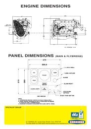
SECTION 9 – General Arrangement6 x Ø1792082060OIL490565<strong>50</strong>218 <strong>50</strong>Detail A178140TOP455171776Detail A80200Detail B4263.5388.8Detail BØ1274 holes Ø11.<strong>50</strong> equi-spacedon 107.90 PCD.RDG7030 <strong>Shire</strong> 06 <strong>Workboat</strong> Owners <strong>Manual</strong>Issue 3 Page 33 of 34
SECTION 10 – Dealer ListCountry Area Company Telephone EmailENGLAND BERKSHIRE Bluenine Marine 01189 406482 bluenine@marine7957.fsnet.co.ukReading Marine Co. Ltd 01189 713666 enquiries@readingmarine.co.ukCHESHIRE Nantwich Canal Centre 01270 625122 info@nantwichcc.comCORNWALL Cellar Marine 01326 280214 john@cellarmarine.comDERBYSHIRE Midland Canal Centre 01283 701933 info@mccboats.co.ukDEVON Sleeman & Hawkin Ltd 01626 778266 keith@sleeman-hawkin.co.ukESSEX French Marine Motors Ltd 01206 305233 chris@frenchmarine.com01255 8<strong>50</strong>303 info@frenchmarine.comHAMPSHIRE Marine Power Ltd 0238 0403918 info@marine-power.co.ukHERTFORDSHIRE P & S Marine 01923 248372LEICESTERSHIRE Foxton Boat Services Ltd 01162 792285 tony@foxton-boats.freeserve.co.ukLONDON De La Hunty Marine 02089 792121 delahuntymarine@btinternet.comNORFOLK French Marine Motors Ltd 01603 722079 info@frenchmarine.comNORTHAMPTON Grand Junction Boat Co. 01604 858043 grandjunco@talk21.comNOTTINGHAM Farndon Marina 01636 705483 info@farndonmarina.co.ukSTAFFORDSHIRE JD Boat Services Ltd 01902 791811 jdboats@btinternet.comStone Boatbuilding Company 01785 812688 sales@stonebuilding.co.ukStreethay Warf 01543 414770 pat@streethaywarf.freeserve.co.ukWARWICKSHIRE Barry Hawkins Narrowboats 01827 711762 boats@hawkinsyard.freeserve.co.ukValley Cruises Ltd 02476 393333 sales@onboardenergy.comWEST MIDLANDS Stephen Goldsbrough Boats 01564 778210 andy@sgboats.comWORCESTERSHIRE J L Pinder & Son 01527 876438 sales@jlpinderandsons.co.ukStarline Narrowboats 01684 874774 narrowboats@starline.demon.co.ukYORKSHIRE Ledgard Bridge Boat Company 01924 493844 mail@ledgardbridge.comRodley Boat Centre 01132 576132 John.snowdenz@ntlworld.comWALES MONMOUTHSHIRE Castle Narrowboats 01873 830001 castlenarrowboats@btinternet.comEIRE Dun Laoghaire Marine Services 00353 12104776O’Sullivans Marine 003536 67124524 brian@sulliansmarine.comRDG7030 <strong>Shire</strong> 06 <strong>Workboat</strong> Owners <strong>Manual</strong>Issue 3 Page 34 of 34