HEAT RECOVERY AND FILTRATION UNITS - Sodeca
HEAT RECOVERY AND FILTRATION UNITS - Sodeca
HEAT RECOVERY AND FILTRATION UNITS - Sodeca

Create successful ePaper yourself
Turn your PDF publications into a flip-book with our unique Google optimized e-Paper software.
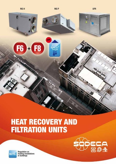
NEW<strong>HEAT</strong> <strong>RECOVERY</strong> <strong>AND</strong><strong>FILTRATION</strong> <strong>UNITS</strong>Regulation onheating installationsin buildings
OURCOMMITMENTTO THEENVIRONMENT<strong>Sodeca</strong> has begun a new stageof study and design of newtrends in ventilation which willhelp to preserve the environmentand to make the energy savingwhich so much concerns today’ssociety.SODECA has concentrated its activity on the production ofindustrial fans, ventilation systems and extractors for the removalof smoke in case of fire since 1983, when it was founded.SODECA’s fans and extractors are present in all Europeancountries and in many parts of the world, thanks to the quality ofthe product and the methods of research and development used.Our quality procedures used and certified by BUREAU VERITAS,in accordance with ISO 9001:2008, are another of the reasonswhich make SODECA one of the best and most renowned fanmanufacturers in Europe.Without a doubt, the most important factor to achieve ourobjectives is the human factor, the great professionals who workat your service, offering not only ventilation equipment but alsosolutions to any ventilation need required by our customers.We sincerely offer you the possibility of visiting our facilities in SantQuirze de Besora, with over 16,000 square metres of built area,where you will be able to see our fan manufacture with perfectclarity and with the highest standards of quality, complying withthe ISO and AMCA standards.This catalogue is only a small part of our possibilities. Do nothesitate to contact us. We will put all our experience and ourhuman resources at your disposal.To obtain an improvementin energy efficiency of fansand of ventilation facilities,the engineering departmentof <strong>Sodeca</strong> has balancedthe energy consumption ofthe fans with their maximumperformance, in the habitualareas of work. This has requireda restructuring of the curvesand their presentation in thisand future <strong>Sodeca</strong> catalogues.installationsheadquarters ofSODECA s.a.,at Sant Quirzede Besora andmanufacturing plantin Santiagode Chile.
<strong>HEAT</strong> <strong>RECOVERY</strong><strong>FILTRATION</strong> <strong>UNITS</strong><strong>Sodeca</strong> has begun a new stage of study and design of new products andtrends related with ventilation, which will help to preserve the environment andto make the energy saving which so much concerns today’s society.Our aims are:• Energy saving and in consequence savingsof natural resources and also economic savings• Improvement in energy efficiency• Reduction of acoustic contamination• Protection of the environmentIn order to fulfil our objectives, SODECA is presenting its new productsin this catalogue so as to fulfil the demands and guidelines of R.I.T.E.(Regulations of Heat Installations in Buildings), and to achieve with theseseries a real energy saving in air-conditioning installations:R.I.T.E.Regulation onheating installationsin buildings• <strong>HEAT</strong> <strong>RECOVERY</strong> <strong>UNITS</strong>• <strong>FILTRATION</strong> <strong>UNITS</strong>Examples of installations according to RITE:IDA 1 ODA 2A<strong>FILTRATION</strong> UNIT + <strong>HEAT</strong> RECOVERER UNITB<strong>FILTRATION</strong> UNITTranslation of literals from the graphFiltro F9: F9 FilterPrefiltro F7: F7 Pre-filterExtracción aire del local: Extraction of air from the premisesEntrada aire fresco y limpio: Entry of frech, clean airImpulsión aire al local: Impulsion of aire from the premisesSalida aire viciado: Outlet of used airA: Solutions with recuperators or combinations of recuperators and filtration unitsB: Solutions with filtration units
<strong>HEAT</strong> <strong>RECOVERY</strong> <strong>UNITS</strong>COMFORT <strong>AND</strong> ENERGY SAVINGWith energy, heat or cold recuperators it will no longer be a problem tocombine the ventilation with the air-conditioning or heating systems.Apart from recovering and conserving energy, the recuperators, withtheir entry filters and air outlet, will make the environment clean andcomfortable.OPERATIONThe heat recuperator operates by means of the combination of two centrifugal fans with a low soundlevel, where one of them carries out the extraction of the used air from the interior of the premises to thestreet, and the other drives fresh air from outside into the interior of the premises. The two circuits crosswithout mixing, in a plate exchanger, where the heat from the outgoing air is transferred to the fresh airfrom the exterior, heating it up.In this way, we manage to recover a high percentage of the energy used to heat up or cool down the air inthe interior of the premises and re-use it. Without the use of the recuperator, this energy would be totallylost.Operating diagram:LOCAL AREAF6B-PF6STREET AREAExtraction of airfrom the premisesFSDTJPFETLEntry of freshclean airImpulsion of airfrom the premisesTJVIBEINTPVETEOutlet ofused airVE: Air extractorVI: Impulsion fanINT: ExchangerBE: Electrical batteryFE: Entry filter F-6FS: Entry filter F-6TJ: Temperature sensor for driven airTL: Temperature sensor for incoming airTE: Temperature sensor for outgoing airDTJ: Humidity and temperature sensorP: Pressure inletBP: By-Pass Hatch
EXAMPLES OF INSTALLATIONGraphic solutions for the fulfilment of minimum filtrations demanded by the R.I.T.E.(F7/F9)IDA 1ODA 1 ODA 2 ODA 3 ODA 4AB(F6/F8)IDA 2ODA 1 ODA 2 ODA 3 ODA 4AB(F6/F7)IDA 3ODA 1 ODA 2 ODA 3 ODA 4ODA 5AB6
(G4/F6)IDA 4ODA 1 ODA 2 ODA 3 ODA 4ODA 5A* B(F6/GF/F9)IDA 1F9ODA 5IDA 2(F6/GF/F9)F8ODA 5A**B**Translation of literals from the graphExtracción aire del local: Extraction of air from the premisesImpulsión aire al local: Impulsion of air from the premisesEntrada aire fresco y limpio: Entry of fresh, clean airSalida aire viciado: Outlet of used airPrefiltro F7: F7 Pre-FilterPrefiltro F6: F6 Pre-FilterPrefiltro G4: G4 Pre-FilterFiltro F6: F6 FilterFiltro F7: F7 FilterFiltro F8: F8 FilterFiltro F9: F9 FilterFiltro GF: GF FilterFiltro F8 o F9: F8 or F9 FilterA: Solutions to the R.I.T.E. with heat recuperators or combinations of recuperators and filtration unitsB: Solutions to the R.I.T.E. with filtration units* Filtration performance better than required by R.I.T.E.** Construction on demand7
SUMMARY OF <strong>HEAT</strong> RECUPERATORSPag 12F6 F7 F9RIS HHigh-efficiency heat recovery, with cross-flow plates and operation withautomatic control Designed to be installed in a horizontal position• High efficiency exchanger (54%-60%)• Filters for high efficiency air supply F6, F7 or F9• Electronics for automatic control, integrated in 400to 1900 models• Double soundproofed wall with 20-30-50 mm. ofsound insulation according to model• Maximum flows from 450 m 3 /h to 6600 m 3 /h• Versions:Environmental: Renewal of airwithout supply of heatElectrical: With supply of heatingby electric batteriesWater battery: With supply ofheating by water batteries• On request: Adiabatic moduleRIS VHigh-efficiency heat recovery, with cross-flow platesand operation with automatic control Design for vertical installation• High efficiency exchanger (54%-60%)• Filters for high efficiency air supply F6, F7 or F9• Electronics for automatic control, integrated in 260to 1900 models• Double soundproofed wall with 20-30-50 mm. ofsound insulation according to model• Maximum flows from 290 m 3 /h to 2.150 m 3 /h• Versions:Environmental: Renewal of airwithout supply of heatElectrical: With supply of heatingby electric batteriesWater battery: With supply ofheating by water batteries• On request: Adiabatic modulem 3 /h0 400 800 1200 1600 2000 2400 2800 3200 3600 4000 4400 4800 5200 5600 6000 6400RIS-5000RIS-4000RIS-3000RIS-2000RIS-1900RIS-1500RIS-1000RIS-700RIS-400RIS-2600 400 800 1200 1600 2000 2400 2800 3200 3600 4000 4400 4800 5200 5600 6000 6400m 3 /hRIS PHighly efficient heat recuperators with crossed flow plates andoperation with automatic control, design for horizontal installation andespecially for false ceilingsPag 16F6 F7 F9• High efficiency exchanger (54%-75%)• Filters for high efficiency air supply F6, F7 or F9• Electronics for automatic control, integrated in 400to 1900 models• Double soundproofed wall with 20-30-50 mm. ofsound insulation according to model• Maximum flows from 450 m 3 /h to 4.300 m 3 /h• Versions:Environmental: Renewal of airwithout supply of heatElectrical: With supply of heatingby electric batteriesWater battery: With supply ofheating by water batteries• On request: Adiabatic modulem 3 /h0 400 800 1200 1600 2000 2400 2800 3200 3600 4000 4400 4800 5200 5600 6000 6400RIS P-400RIS P-2000RIS P-1900RIS P-1500RIS P-1000RIS P-700RIS P-30000 400 800 1200 1600 2000 2400 2800 3200 3600 4000 4400 4800 5200 5600 6000 6400m 3 /h8
F6 F6 filter F7 F7 filter F6 + F6 + F8F8filterF9 F9 filterSoundlevelModuleAdiabaticEnvironmentalElectricalBy hotwaterF6F6 + F8RECUPConfigurable heat recuperators with crossed flow plates,for horizontal installation (H)• Exchanger with aluminium plates with efficiencybetween 52% and 55%• Air supply filters F6 or F6+F8• Galvanised steel box with built-in soundproofing• Maximum flows from 500 m 3 /h to 6100 m 3 /h• Versions:Environmental: Renewal of airwithout supply of heat• On request: Adiabatic modulePag 19m 3 /h0 400 800 1200 1600 2000 2400 2800 3200 3600 4000 4400 4800 5200 5600 6000 6400RECUP-60RECUP-50RECUP-40RECUP-30RECUP-20RECUP-12RECUP-08RECUP-050 400 800 1200 1600 2000 2400 2800 3200 3600 4000 4400 4800 5200 5600 6000 6400m 3 /hF7RIRSVery highly efficient heat recuperators with rotating exchanger and operationwith automatic control. Designed to be installed in a horizontal position• High efficiency rotational exchanger(70%-77%)• Filters for F7 high efficiency air supply• Electronics for automatic control, integrated in 400to 1500 models• Double soundproofed wall with 50 mm.of sound insulation• Maximum flows from 425 m 3 /h to 6700 m 3 /h• Versions:Environmental: Renewal of airwithout supply of heatElectrical: With supply of heatingby electric batteriesWater battery: With supply ofheating by water batteriesm 3 /h0 400 800 1200 1600 2000 2400 2800 3200 3600 4000 4400 4800 5200 5600 6000 6400Pag 21RIRS-3000RIRS-2000RIRS-1500RIRS-700RIRS-4000 400 800 1200 1600 2000 2400 2800 3200 3600 4000 4400 4800 5200 5600 6000 6400m 3 /hRIRS-4000AccessoriesAccessoriesSee accessories sectionCJFILTERAir filter boxesfor circular ductsequipped withdifferent types of filter,according to model.CJFILTER 100Diameter100 / 125150 / 200250 / 315355 / 400F6FiltersG4 / F5F6 / F7F8 / F9ADIABATIC BOXBox which incorporates an adiabatic moduleIt contributes to the cooling of the airsupply to the premises It is installed in theextraction circuit between the pre-filter andthe exchanger.UNIPROBOX-EFILTERSCJFILTERADIABATIC BOX9
G4 G4 filterF6F6 filterF7F7 filterF8F8 filterF9F9 filterSound levelF6F7F8F9UFXSoundproofed filtration units equipped with double inlets and differentstages of filtration according to model.• Belt-driven• Built-in general bed• F6 + F8, F7 + F9 and G4 + F6 filters according tomodel selected• Possibility of pre-filter plus two stagesm 3 /h0 5000 10000 15000 20000 25000 30000 35000 40000 45000of filtration• Easy access inspection and cleaning cover• Pressure inlets for filter control• Built-in pressure probePag 32G4F612/1218/1815/1520/2022/2225/2530/280 5000 10000 15000 20000 25000 30000 35000 40000 45000m 3 /hPag 42UFRXSoundproofed filtration units equipped with double inlet fans and very robustreaction turbine and different stages of filtration according to model.• Belt-driven• Built-in general bed• F6 + F8, F7 + F9 and G4 + F6 filters• Possibility of pre-filter plus two stagesof filtration• Easy access inspection and cleaning covers• Pressure inlets and pressure probe for filter control• On request: Absolute active carbon filtersm 3 /h0 5000 10000 15000 20000 25000 30000 35000 40000 45000F6F7G4F8F9F63153554004505005606300 5000 10000 15000 20000 25000 30000 35000 40000 45000m 3 /hAccessoriesSee accessories sectionFILTERSCJFILTERPRESOSTATOSI-PRESSURECONSTANT FLOW KITPRESSUREPROBEINTVISTEJGENERALBEDPLATESILENT-BLOCKS11
RIS H/VHighly efficient heat recuperators with crossed flow plates forautomatic operation and control of the recuperator, according toselected parameters of temperature and humidity (models 260 to1900). Designed for horizontal (H) or vertical (V) installationF6 F7 F9UNI Controller included in RIS 260 to RIS1900 modelsFeatures:• High efficiency exchanger (54%-60%)• Filters for high efficiency air supply F6,F7 or F9• Electronics for automatic control,integrated in 260 to 1900 models with UNIcontroller included• Electronic for automatic control, as anaccessory (BOX-E) in models 2000 to5000, for the control it is necessary torequest the UNI or PRO panel as anaccessory• Double soundproofed wall with 50 mm ofhigh absorption soundproofing (models260 with 20 mm and models 400-700 with30 mm)• Input and output temperature sensor (size1000 to 1900)• Humidity sensor according to model (size1000 to 1900)• Built-in bypass hatch• Tray for collecting condensation instainless steel and with drainage valveConstruction:• Metallic structure• Double-wall panels, with soundproofing of30-50 mm. thickness• Input and output vents with airtight joint• Large access doors to facilitatemaintenance and cleaning. In thehorizontal version, the doors areexchangeable so as to be able to carryout the maintenance on the right and theleft, seen through the vents.Versions:• Horizontal (H) or Vertical (V)• Vertical up to size 1900 (V)• Environmental: Renewal of air withoutsupply of heat (S)• Electric: With supply ofheating by electricbatteries (E)• Water battery: With supply ofheating by waterbatteries (W)• On request: Adiabatic moduleOrder codeRIS 1000 H E D F6 MAModelAccessoriesSizeH: Horizontal ductsV: Vertical ductsS: EnvironmentalE: ElectricW: Water batteryD: Entry of fresh, clean air fromthe exterior on the right-handsideK: Entry of fresh, clean air fromthe exterior via the left-hand sideF6 filterF7 filterF9 filterModuleAdiabaticSee accessories sectionUNI PRO BOX-E FILTERS CJFILTER ADIABATIC BOX PRESOSTATO SI-PRESSURE INT TEJGENERALBEDPLATESILENT-BLOCKS12
<strong>HEAT</strong> <strong>RECOVERY</strong> <strong>UNITS</strong>Technical characteristicsModelSpeed(r/min)Voltage(V)Current(A)Powermotor(W)MaxAIrflowF6(m 3 /h)Max.AirflowF7(m 3 /h)Thermalefficiency(%)RIS-400S 2100 1x230 2x1.1 2x225 450 60 34 F6/F7 47RIS-700S 2000 1x230 2x1.12 2X255 950 60 41 F6/F7 62RIS-1000S 2650 1x230 2x0.81 2x185 1300 1180 54 42 F6/F7 149RIS-1500S 2750 1x230 2x1.23 2x280 1650 1450 54 44 F6/F7 179RIS-1900S 2830 1x230 2x2.7 2x610 2150 2030 60 46 F6/F7 308RIS-2000S 1310 3x400 2x2.6 2x1500 2600 2470 60 49 F6/F7 324RIS-3000S 1300 3x400 2x4.1 2x2500 4300 3760 59 50 F6/F7 393RIS-4000S 2090 3x400 2x4.7 2x2200 5000 3850 58 51 F6/F7 498RIS-5000S 1867 3x400 2x6.47 2x3000 6000 4680 58 52 F6/F7 568RIS-260E 1880 1x230 2x0.4 2x89 280 55 31 6.4 F6/F7 40 1x230 1RIS-400E 2100 1x230 2x1.1 2x225 450 60 34 14.8 F6/F7 48 1x230 2RIS-700E 2000 1x230 2x1.12 2X255 950 60 41 20.5 F6/F7 70 1x230 3RIS-1000E 2650 1x230 2x0.81 2x185 1300 1180 54 42 10.6 F6/F7 150 3x400 6RIS-1500E 2750 1x230 2x1.23 2x280 1650 1450 54 44 16.2 F6/F7 180 3x400 9RIS-1900E 2830 1x230 2x2.7 2x610 2150 2030 60 46 27 F6/F7 310 3x400 15RIS-2000E 1310 3x400 2x2.6 2x1500 2600 2470 60 49 26.9 F6/F7 328 3x400 15RIS-3000E 1300 3x400 2x4.1 2x2500 4300 3760 59 50 44.7 F6/F7 395 3x400 24RIS-4000E 2090 3x400 2x4.7 2x2200 5000 3850 58 51 50.4 F6/F7 500 3x400 27RIS-5000E 1867 3x400 2x6.47 2x3000 6000 4680 58 52 63.1 F6/F7 570 3x400 33RIS-400W 2100 1x230 2x1.1 2x225 450 60 34 F6/F7 52 2.7*RIS-700W 2000 1x230 2x1.12 2X255 950 60 41 F6/F7 63 4.7*RIS-1000W 2650 1x230 2x0.81 2x185 1300 1180 54 42 F6/F7 150 6.75*RIS-1500W 2750 1x230 2x1.23 2x280 1650 1450 54 44 F6/F7 180 10.12*RIS-1900W 2830 1x230 2x2.7 2x610 2150 2030 60 46 F6/F7 310 12.82*RIS-2000W 1310 3x400 2x2.6 2x1500 2600 2470 60 49 F6/F7 326 15.6*RIS-3000W 1300 3x400 2x4.1 2x2500 4300 3760 59 50 F6/F7 395 20.2*RIS-4000W 2090 3x400 2x4.7 2x2200 5000 3850 58 51 F6/F7 500 26.0*RIS-5000W 1867 3x400 2x6.47 2x3000 6000 4680 58 52 F6/F7 570 32.0** Values measured with exterior air temperature of +18ºC and water temperature of Tin/Tout 80/60 ºCIrradiatedNPSdB(A)CurrentTotal(A)Electrical B. Water B.Filter Weight Voltage ResistanceEN 779 (Kg) (V)Power(kW)Thermalpower(kW)ConfigurationsConfiguration D standard supplyHorizontal version DVertical version DF6F6Horizontal version KF6F6Vertical version KTranslation of literals from the graphZONA LOCAL: LOCAL AREAZONA CALLE: STREET AREAExtracción aire del local: Extraction of air from the premisesImpulsión aire del local: Impulsion of air from the premisesEntrada aire fresco y limpio: Entry of fresh, clean airSalida aire viciado: Outlet of used air13
Dimensions in mmModel A B C Ø D H1 H2 H3 H4 H5 WRIS-400H 1170 600 354 160 250 190 250 190 55 200RIS-700H 1320 600 504 250 150 310 150 310 55 252RIS-1000H 1500 905 645 315 233 400 233 400 - -RIS-1500H 1500 905 645 315 233 400 233 400 - -RIS-1900H 1800 1120 790 400 275 500 275 500 - -RIS-2000H 2100 1050 790 400 265 510 265 510 - 395RIS-3000H 2400 1130 830 400 350 500 350 500 - 300Model A A1 A2 B C H1 H2 K k L l W1 W2RIS-4000H 3000 2000 1000 1244 584 178 35 500 260 500 260 162 36RIS-5000H 3000 2000 1000 1242 832 191 34 710 332 562 332 412 87RIS-260VRIS-400VRIS-700VRIS-1000VRIS-1500VRIS-1900VModel A B C Ø D H1 X1 X2 X3 Y1 Y2 Y3 Y4 Y5RIS-260V 598 640 295 125 690 135 70 90 90 129 160 129 90RIS-400V 900 800 352 160 850 166 60 126 130 205 230 205 130RIS-700V 950 845 462 200 895 182 120 160 140 212 246 212 140RIS-1000V 1400 1000 645 315 1070 250 187 208 207 328 330 328 207RIS-1500V 1400 1000 645 315 1070 250 187 208 210 325 330 325 210RIS-1900V 1650 1100 790 400 1170 292 248 250 225 395 410 395 22514
<strong>HEAT</strong> <strong>RECOVERY</strong> <strong>UNITS</strong>Characteristic curvesRIS-260 / RIS-400 / RIS-700RIS-1000 / RIS-1500 / RIS-1900RIS-2000 / RIS-3000RIS-4000 / RIS-500015
RIS PEfficiency heat recoveries and low silhouette, for automaticoperation and control of the recuperator. Designed for horizontalinstallation in false ceilings.F6 F7 F9General characteristics:• High efficiency exchanger (54%-75%)• 2 Air filters of F6, F7 efficiencies made withlow-loss loading bags (F9, please consult).• Electronics for automatic control,integrated in 260 to 1900 models with UNIcontroller included.• Electronic for automatic control, as anaccessory (BOX-E) in models 2000 to 3000,for the control it is necessary to request theUNI or PRO panel as an accessory.• Input and output temperature sensors (size400 to 1900)• Humidity sensor, size 1000 to 1900.• Built-in bypass hatch in models 1000 to3000.• Bypass automatic control in models 1000to 1900.Construction:• Metallic structure• Double-wall panels, with soundproofing of30 mm. thickness in 400 and 700, and 60mm. in the rest.• Input and output vents with airtight joint• Lower access doors to facilitatemaintenance and cleaning.Versions:• Horizontal: For false ceiling• Environmental: Renewal of airwithout supply of heat (S)• Electric: With supply ofheating by electricbatteries (E)On request:• Adiabatic module• 2 configurations of outlets accordingto model (see diagrams of D or Kconfigurations)UNI Controller included from RIS-400 toRIS-1900 equipmentsOrder codeImpeller detailFilters detailRIS 400 P E D F6 MATechnical characteristicsModelModelSizeSpeed(r/min)FansVoltage(V)Flat designfor suspendedceilingCurrent(A)Power(W)S: EnvironmentalE: ElectricMax.AirflowF6(m 3 /h)Max.AirflowF7(m 3 /h)D: Entry of air from the exterioron the right-hand sideK: Entry of air from the exterioron the left-hand sideThermalefficiency(%)IrradiatedNPSdB(A)Totalcurrent(A)FilterEN 779F6 filterF7 filterF9 filterWeight(Kg)AdiabaticmoduleElectrical B.Voltage(V)Resistancepower(kW)RIS-1000-P-S 2250 1x230 2x1.36 2x312 1300 1180 51 42 2.61 F6/F7 113RIS-1500-P-S 2750 1x230 2x1.63 2x373 1650 1450 62 44 3.2 F6/F7 189RIS-1900-P-S 2830 1x230 2x2.95 2x669 2150 2030 60 46 5.9 F6/F7 290RIS-2000-P-S 1310 3x400 2x1.94 2x885 2600 2470 60 49 3.88 F6/F7 324RIS-3000-P-S 1300 3x400 2x2.58 2x1388 4300 3760 59 50 5.05 F6/F7 393RIS-400-P-E 1850 1x230 2x0.77 2x174 500 450 75 44 14.52 F6/F7 42 1x230 2RIS-700-P-E 2000 1x230 2x0.92 2x212 750 650 57 45 20.1 F6/F7 57 1x230 3RIS-1000-P-E 2250 1x230 2x1.36 2x312 1300 1180 51 42 11.27 F6/F7 113 3x400 6RIS-1500-P-E 2750 1x230 2x1.63 2x373 1650 1450 62 44 16.19 F6/F7 194 3x400 9RIS-1900-P-E 2830 1x230 2x2.95 2x669 2150 2030 60 46 27.55 F6/F7 310 3x400 15RIS-2000-P-E 1310 3x400 2x1.94 2x885 2600 2470 60 49 25.53 F6/F7 328 3x400 15RIS-3000-P-E 1300 3x400 2x2.58 2x1388 4300 3760 59 50 44.7 F6/F7 395 3x400 24Notes: * Thermal efficiencies calculated with a temperature differential +20 ºC inside / -20 ºC outside, 60% internal humidity, 90% external humidity.* Irradiated sound pressure level are free field at 1.5 m * Equipment with a fan or three-phase battery should be connected with three phases + neutral + earth.16
<strong>HEAT</strong> <strong>RECOVERY</strong> <strong>UNITS</strong>ConfigurationsConfiguration D standard supply.Horizontal version DDiagrams according to top view (theopposite side to the inspection door).K version only available for1900, 2000 and 3000 models.F6F6Horizontal version KTranslation of literals from the graphZONA LOCAL: LOCAL AREAZONA CALLE: STREET AREAExtracción aire del local: Extraction of air from the premisesImpulsión aire del local: Impulsion of air from the premisesEntrada aire fresco y limpio: Entry of fresh, clean airSalida aire viciado: Outlet of used airF6F6Dimensions in mmModel A B C ØD H1 H2 H3 W1 W2 X ZRIS-400-P 970 615 264 160 125 120 75 125 140 830 592RIS-700-P 1200 775 300 250 190 190 75 134 134 1040 752RIS-1000-P 1500 943 495 315 206 206 93 245 245 1124 890Model A B C D G H1 H2 H3 W1 X ZRIS-1500-P 1900 1363 549 500 250 325 325 93 248 1524 1310InsideModel A B C ØD H1 H2 W1RIS-1900-P 1800 1120 790 400 275 500 395RIS-2000-P 2100 1080 790 400 280 520 395OutsideRISP-3000-P/DInsideOutsideRISP-3000-P/K17
Characteristic curvesRIS P-400E / RIS P-700ERIS P-1000 / RIS P-1500 / RIS P-1900RIS P-2000 / RIS P-3000AccessoriesSee accessories sectionUNI PRO BOX-E FILTERS CJFILTER ADIABATIC BOX PRESOSTATO SI-PRESIÓN INT TEJGENERALBEDPLATESILENT-BLOCKS18
<strong>HEAT</strong> <strong>RECOVERY</strong> <strong>UNITS</strong>RECUPF6F6F8Configurable heat recovery, with cross-flow plates forhorizontal (H) or vertical (V) installationRECUP-HFeatures:• Exchanger with aluminium plates withefficiency between 52% and 55%• Possibility of configuration between differentvent positions• Built-in filters, F6 and F6+F8 quality. Othercombinations on request.• Galvanised steel box with built-insoundproofingConstruction:• Galvanized sheet steel structure.• Input and output vents with airtight joint• Exchangeable vents• Large access doors to facilitatemaintenance and cleaning.Versions:• Horizontal (H) or Vertical (V)• Environmental: Renewal of airwithout supply of heat (S)• Electric: With supply ofheating by electricbatteries (EB)• Water battery: With supply ofheating by waterbatteries (WB)• On request: Adiabatic moduleRECUP-VOrder codeRECUP 20 H C F6 MAModelSizeH: Horizontal configurationV: Vertical configurationA-F: Inlet/outlet positions F6 filter(Standard C or B according F6+F8 filterto models)G4 filterMA: Adiabatic moduleEB: Electrical batteryWB: Water batteryTechnical characteristicsModelSpeed(r/min)Voltage(V)Current(A)Powermotor(W)MaxAIrflowF6(m 3 /h)Thermalefficiency(%)IrradiatedNPSdB(A)FilterEN 779RECUP-05-H 1400 1x230 1.2 2x140 500 50 42 G4, F6, F6+F8 33RECUP-08-H 1420 1x230 2.7 2x310 950 52 49 G4, F6, F6+F8 45RECUP-12-H 1425 1x230 4.0 2x450 1300 52 53 G4, F6, F6+F8 67RECUP-20-H 1350 1x230 4.0 2x450 2050 52 48 G4, F6, F6+F8 86RECUP-20-V 1350 1x230 4.0 2x450 2050 52 48 G4, F6, F6+F8 86RECUP-30-H 1250 1x230 5.4 2x600 3150 54 52 G4, F6, F6+F8 112RECUP-30-V 1250 1x230 5.4 2x600 3150 54 52 G4, F6, F6+F8 112RECUP-40-H 900 3x400 3.6 2x1100 4250 55 46 G4, F6, F6+F8 167RECUP-40-V 900 3x400 3.6 2x1100 4250 55 46 G4, F6, F6+F8 167RECUP-50-H 1280 3x400 3.5 2x1500 5350 53 54 G4, F6, F6+F8 182RECUP-50-V 1280 3x400 3.5 2x1500 5350 53 54 G4, F6, F6+F8 182RECUP-60-H 1450 3x400 6.5 2x3000 6150 50 56 G4, F6, F6+F8 205RECUP-60-V 1450 3x400 6.5 2x3000 6150 50 56 G4, F6, F6+F8 205Weight(Kg)19
Configurations (Horizontal version)Configuration C standard supply. Except models 05, 08 and 12 configuration B.Configuration (A) Configuration (B) Configuration (C) Configuration (D) Configuration (E) Configuration (F)SVAF SVEL ILELAFELFilter FilterAFELFilter FilterSVILFilter FilterAFFilter FilterAFFilter FilterILELAFFilter FilterILILEL ILSVSVAF: External fresh air / IL: Impulsion of air to the premises / SV: Outlet of used air / EL: Extraction of air from the premisesSVDimensions in mmModels A B L øD H1 H2 H3 W W1 Weight(Kg)RECUP-05-H 324.5 630 630 200 167.5 295 167.5 148 148 33RECUP-08-H 346 800 800 250 210 380 210 181 181 45RECUP-12-H 396 1000 1000 315 235 530 235 198 198 67RECUP-20-H 500 1020 1020 315 246.5 557 246.5 300 269 86RECUP-30-H 600 1102 1202 315 270 662 270 385 368 112RECUP-40-H 670 1500 1500 450 344.5 811 344.5 379 379 167RECUP-50-H 805 1500 1700 450 347 1006 347 440 402.5 182RECUP-60-H 805 1500 1700 450 347 1006 347 440 402.5 195Models A B B1 L øD H1 H2 H3 W W1 W2 W3RECUP-05-H 300 630 1062 628 200 171 286 171 150 150 150 150RECUP-08-H 350 800 1232 800 250 200 400 200 175 175 175 175RECUP-12-H 415 1000 1432 1000 315 250 500 250 207.5 207.5 207.5 207.5RECUP-20-H 500 1050 1486 1050 315 246.5 557 246.5 250 269 300 269RECUP-30-H 600 1102 1540 1202 315 270 662 270 300 369 385 368RECUP-40-H 670 1500 1931 1500 450 344.5 811 344.5 335 378.5 378 378.5RECUP-50-H 805 1500 1931 1700 450 347 1006 347 402.5 402.5 440 402.5RECUP-60-H 805 1500 1931 1700 450 347 1006 347 402.5 402.5 440 402.520
Dimensions in mmModels A A1 B B1 L øD H1 H2 H3 W W1RECUP-20-V 500 620 1050 30 1050 315 298 501 251 250 250RECUP-30-V 600 720 1202 30 1102 315 384 548 270 300 300RECUP-40-V 670 790 1500 30 1500 450 391.5 739 369.5 334 335RECUP-50-V 805 925 1700 30 1500 450 441 912 347 402.5 402.5RECUP-60-V 805 925 1700 30 1500 450 441 912 347 402.5 402.5Models A A1 B B1 L L1 øD H1 H2 H3 H4 W W1RECUP-20-V 500 620 1050 30 1050 1487 315 252 501 251 298 250 250RECUP-30-V 600 720 1202 30 1102 1540 315 335 548 270 384 300 300RECUP-40-V 670 790 1500 30 1500 1933 450 369.5 739 369.5 391.5 334 335RECUP-50-V 805 925 1700 30 1500 1933 450 403.5 912 347 441 402.5 402.5RECUP-60-V 805 925 1700 30 1500 1933 450 403.5 912 347 441 402.5 402.521
Acoustic featuresThe specified values are determined according to free field measurements of sound levels in dB(A) at a distance not less than 1.5 m ofequipment.Sound power Lw(A) spectrum in dB(A) via frequency band in Hz.Model 63 125 250 500 1000 2000 4000 8000RECUP-05 45 47 38 31 39 28 21 21RECUP-08 52 54 44 37 50 37 34 30RECUP-12 54 56 49 52 54 50 45 38RECUP-20 49 51 44 47 49 45 40 33Model 63 125 250 500 1000 2000 4000 8000RECUP-30 54 56 50 51 48 43 35 31RECUP-40 49 51 43 37 36 30 29 15RECUP-50 57 59 50 44 42 36 37 22RECUP-60 59 61 52 46 44 38 39 24Characteristic curvesRECUP-05 / RECUP-08 / RECUP-12 / RECUP-20RECUP-30 / RECUP-40 / RECUP-50 / RECUP-60AccessoriesSee accessories sectionFILTERSCJFILTER ADIABATIC BOX WATER BATERY ELECTRICAL PRESOSTATO SI-PRESIÓN INT TEJFOR RECUP BATTERYFOR RECUPVISGENERALBEDPLATESILENT-BLOCKS22
<strong>HEAT</strong> <strong>RECOVERY</strong> <strong>UNITS</strong>RIRSVery high efficiency heat recuperators with rotating exchanger forautomatic operation and control of the recuperator, according toselected parameters of temperature and humidity(models 400 to 1500). Designed for horizontal (H) installationF7Features:• High efficiency exchanger (70%-77%)• Filters for F7 high efficiency air supply• Electronics for automatic control,integrated in 400 to 1500 models with UNIcontroller included• Electronic for automatic control, as anaccessory (BOX-E) in models 2000 to4000, for the control it is necessary torequest the UNI or PRO panel as anaccessory• Double soundproofed wall with 50 mm. ofhigh-absorption sound insulation• Fans with external rotor motorConstruction:• Metallic structure• Double-wall panels, with soundproofing of50mm. thickness• Exchangeable inspection plate.• Input and output vents with airtight joint• Large access doors to facilitatemaintenance and cleaning. In thehorizontal version, the doors areexchangeable up to 1500 model so as tobe able to carry out the maintenance onthe right and the left, seen through thevents.Versions:• Horizontal (H)• Electric: With supply ofheating by electricbatteries (E)• Water battery: With supply ofheating by water batteries (W)UNI Controller included in RIRS 400 toRIRS 1500 modelsOrder codeRIRS 1000 H E DModelSizeHorizontal ductsE: ElectricW: Water batteryD: Entry of fresh, clean air from theexterior on the right-hand sideK: Entry of fresh, clean air from theexterior via the left-hand sideTechnical characteristicsModelSpeed(r/min)Voltage(V)Current(A)Powermotor(W)Max.Airflow(m 3 /h)Thermalefficiency(%)IrradiatedNPSdB(A)Totalcurrent(A)FilterEN 779Electrical B. Water B.Weight Voltage Resistance(Kg) (V) power(kW)RIRS-400E 1850 1x230 0.84 2x190 450 75 34 6.91 F7 70 1x230 1.2RIRS-700E 2050 1x230 1.31 2x300 950 74 41 11.39 F7 96 1x230 2RIRS-1500E 2750 1x230 1.71 2x390 1650 74 44 10.07 F7 159 3x400 4.5RIRS-2000E 1310 3x400 2.6 2x1500 2600 70 49 18.5 F7 260 3x400 9RIRS-3000E 1300 3x400 4.1 2x2500 4100 77 50 30.2 F7 410 3x400 15RIRS-4000E 1320 3x400 6 2x3700 6500 71 53 38.3 F7 490 3x400 18RIRS-1500W 2750 1x230 1.71 2x390 1650 74 44 F7 165 5.45RIRS-2000W 1310 3x400 2.6 2x1500 2600 70 49 F7 260 9.5RIRS-3000W 1300 3x400 4.1 2x2500 4100 77 50 F7 410 11.21RIRS-4000W 1320 3x400 6 2x3700 6500 71 53 F7 490 16.29Thermalpower(KW)23
SV/FILTERLow noise in-line duct fans with different stages of filtration.G4F6Features:• Acoustic casing covered with soundabsorbing material.• Standard aspiration and impulsion jointsto aid in duct installation.• G4 + F6, F6 + F8 and F7 + F9 filtersaccording to model• Easy access inspection and cleaningcoverConstruction:• Galvanized sheet steel casing• Backward-curved turbine, except models125 and 150, which have a multi-bladeimpeller. Supplied with four supportingfeet, to facilitate assembly.• Large access doors to facilitatemaintenance and cleaning.Motor:• Class F motors with external rotor, ballbearings, IP54 protection, and built-inthermal protector• 230V single-phase. -50/60Hz. Adjustable• Max. temperature of air for transport+50ºCFinish:• Anticorrosive finish in polyester resin,polymerised at 190ºC, after alkalinedegreasing and phosphate-freepre-treatment.F6F8F7F9Order codeSV/FILTER 200/H F7+F9ModelSizeFiltercombinationTechnical characteristicsModelSpeed(r/min)Maximumadmissiblecurrent (A) 230VPowerinstalled(kW)(G4+F6)filtersAirflow Maximum(m 3 /h)(F6+F8)filters(F7+F9)filtersNo. No.Pre-filters FiltersFilter Dimensions(mm)(G4) (F) filtersfiltersSV/FILTER-125/H 2220 0.65 0.08 300 255 240 1 1 282x194x48 282x194x98 9.1SV/FILTER-150/H 2200 1.25 0.17 445 385 360 1 1 334x216x48 334x216x98 12.3SV/FILTER-200/H 1240 0.85 0.12 515 520 390 1 1 389x248x48 389x248x98 15.1SV/FILTER-250/H 2380 0.95 0.14 660 560 525 1 1 414x267x48 414x267x98 17.8SV/FILTER-315/H 1330 0.75 0.12 1035 850 790 1 1 513x344x48 513x344x98 26.4SV/FILTER-350/H 1280 0.95 0.14 1550 1270 1180 1 1 602x385x48 602x385x98 36.3SV/FILTER-400/H 1330 1.80 0.30 2050 1720 1600 1 1 660x405x48 660x405x98 46.4Weight(Kg)26
<strong>FILTRATION</strong> <strong>UNITS</strong>Dimensions in mmModel A B C1 C2 Ø D1 L Ø D2 EC1 EC2 TSV/FILTER-125/H 657 290 80 222 125 36,5 7 607 240 730SV/FILTER-150/H 700 340 92 244 150 36,5 7 650 290 773SV/FILTER-200/H 775 395 117 273 200 36 7 725 345 847SV/FILTER-250/H 775 395 140 293 250 50 7 725 345 875SV/FILTER-315/H 860 520 175 371 315 48 8.5 809 469 956SV/FILTER-350/H 960 610 200 410 355 48 8.5 909 564 1056SV/FILTER-400/H 1035 670 219 455 400 38 8.5 984 624 1111Characteristic curvesEquipment curve according to built-in filters 1 G4+F6 2 F6+F8 3 F7+F9Static pressure Dynamic pressure Absorbed powerSV/FILTER125/HSV/FILTER150/HPaPaPdPd27
Characteristic curvesEquipment curve according to built-in filters 1 G4+F6 2 F6+F8 3 F7+F9Static pressure Dynamic pressure Absorbed powerSV/FILTER200/HSV/FILTER250/HPaPaPdPdSV/FILTER315/HSV/FILTER350/HPaPaPdPd28
<strong>FILTRATION</strong> <strong>UNITS</strong>Characteristic curvesEquipment curve according to built-in filters 1 G4+F6 2 F6+F8 3 F7+F9Static pressure Dynamic pressure Absorbed powerSV/FILTER400/HPaPdAccessoriesSee accessories sectionFILTERS CJFILTER PRESOSTATO SI-PRESIÓN PRESSURE INT VISTEJPROBE29
UFRSoundproofed filtration units with sandwich panel, equipped withhigh-performance reaction turbine fans and different stages offiltration according to model.F6F7F8F9Features:• Soundproofed structure• Direct operation• Impulsion of air, configurable by 4 laterals• F6 + F8, F7 + F9 and G4 + F6 filtersaccording to model selected• Possibility of pre-filter plus two stages offiltration• Easy access inspection and cleaningcover• Pressure inlets for filter control• Pressure probe for filter controlConstruction:• Galvanised sheet steel structure withsoundproofing.• High-performance impeller withbackward-curved blades made fromsheet steel• Built-in general bed• Easy access inspection and cleaningcoversMotor:• Class F motors, with bearings, IP55protection.• Three-phase 230/400V.-50Hz. (up to5.5CV.) and 400/690V.-50Hz. (power over5.5CV.)• Temperature of the air to be displaced-20ºC.+60ºC.Finish:• Anticorrosive galvanized sheet steelG4F6Order codeUFR 2056 6T F7+F9Model SizeMotor poles: Three-phase Combination of filters4 poles: 1,500 r/min6 poles: 900r/minTechnical characteristicsModelSpeed(r/min)Maximum admissiblecurrent (A)230V 400V 690VPowerinstalled(kW)MaximumAirflow(m 3 /h)(F6+F8)filtersMaximumAirflow(m 3 /h)(F7+F9)filtersMaximumAirflow(m 3 /h)(G4+F6)filtersNo. Pre-filtersNumber offiltersWhole* Medium* Whole* Medium*UFR-1240-4T 1430 3.34 1.93 0.75 3,245 3,185 3,005 1 0 1 0 107.5UFR-1850-4T 1420 5.97 3.45 1.50 4,705 4,620 4,350 1 0 1 0 110UFR-2056-4T 1430 8.38 4.84 2.20 7,680 7,580 7,235 1 2 1 2 168.5UFR-2056-6T 935 3.77 2.18 0.75 5,325 5,250 5,010 1 2 1 2 163UFR-2263-4T 1460 11.03 6.37 5.50 11,995 11,680 11,375 1 2 1 2 221.5UFR-2263-6T 950 5.23 3.02 1.10 7,200 7,100 7,000 1 2 1 2 177.5UFR-2071-4T 1460 20.64 11.92 11.00 15,045 14,535 14,060 1 2 1 2 265UFR-2071-6T-3 940 9.28 5.36 2.20 9,175 8,990 8,810 1 2 1 2 195UFR-2071-6T-5.5 970 16.35 9.44 4.00 10,130 9,770 9,440 1 2 1 2 241.5UFR-2880-6T 970 16.35 9.44 4.00 11,500 11,165 10,845 1 2 1 2 242* Pre-filter dimensions: Full: 585x585x48. Half: 290x585x48* Filter dimensions: Full: 593x593x292. Half: 288x593x292Weight(Kg)30
<strong>FILTRATION</strong> <strong>UNITS</strong>Dimensions in mmModel A B C D E Ø d X ZUFR-1240-4T 800 800 950 700 640 M6 800 1906UFR-1850-4T 800 800 950 700 640 M6 800 1906UFR-2056-4T 925 925 1000 823 763 M6 925 2081UFR-2056-6T 925 925 1000 823 763 M6 925 2081UFR-2263-4T 1000 1000 1000 960 838 M6 1000 2156UFR-2263-6T 925 925 1000 960 763 M6 925 2081UFR-2071-4T 1060 1060 1000 960 900 M6 1060 2216UFR-2071-6T 1000 1000 1000 960 838 M6 1000 2156UFR-2071-6T-5,5 1060 1060 1000 960 900 M6 1060 2216UFR-2880-6T 1060 1060 1000 960 900 M6 1060 2216Characteristic curvesEquipment curve according to built-in filters 1 F6+F8 2 F7+F9 3 G4+F6Static pressure Dynamic pressure Absorbed powerUFR-1240-4TUFR-1850-4TPe (in wg)1,6Pe (Pa)400Pe(mmca)400 500 1000 1500 2000PaQ (cfm)Pa (W)500Pe (in wg)2,8Pe (Pa)700Pe(mmca)700 500 1000 1500 2000 2500Q (cfm)PaPa (W)12001,2300304002,42,0600500605010008000,80,42001002010123Pd3002001001,61,20,80,440030020010040302010123600400200Pd0,0000 1000 2000 300003Q (m /h)0,0000 1000 2000 3000 400003Q (m /h)0,0 0,2 0,4 0,6 0,8 1,03Q (m /s)0,0 0,2 0,4 0,6 0,8 1,0 1,23Q (m /s)31
Characteristic curvesEquipment curve according to built-in filters 1 F6+F8 2 F7+F9 3 G4+F6Static pressure Dynamic pressure Absorbed powerUFR-2056-4TUFR-2056-6TPe (in wg)3,63,2Pe (Pa)900800Pe(mmca)0 1000 2000 3000 4000 500010080PaQ (cfm)Pa (W)Pe (in wg)1,6Pe (Pa)400Pe(mmca)400 500 1000 1500 2000 2500 3000 3500PaQ (cfm)Pa (W)5002,870015001,2300304002,4600602,050010003001,6400400,8200201,20,830020020125000,4100101232001000,4100Pd3Pd0,0000 2000 4000 6000 800003Q (m /h)0,0000 1000 2000 3000 4000 500003Q (m /h)0,0 0,5 1,0 1,5 2,03Q (m /s)0,0 0,2 0,4 0,6 0,8 1,0 1,2 1,43Q (m /s)UFR-2263-4TUFR-2263-6TPaPaPdPdAccessoriesSee accessories sectionFILTERSCJFILTERPRESOSTATOSI-PRESIÓNCONSTANT FLOW KITPRESSUREPROBEINTVIS32
<strong>FILTRATION</strong> <strong>UNITS</strong>Characteristic curvesEquipment curve according to built-in filters 1 F6+F8 2 F7+F9 3 G4+F6Static pressure Dynamic pressure Absorbed powerUFR-2071-4TUFR-2071-6T-3PaPaPdPdUFR-2071-6T-5,5UFR-2880-6TPaPaPdPdAccessoriesSee accessories sectionTEJGENERALBEDPLATESILENT-BLOCKS33
UFXSoundproofed filtration units equipped with double inlets anddifferent stages of filtration according to model.F6F7G4F8F9F6Features:• Soundproofed structure• Belt-driven• F6 + F8, F7 + F9 and G4 + F6 filtersaccording to model selected• Possibility of pre-filter plus two stages offiltration• Easy access inspection and cleaningcover• Pressure inlets for filter control• Built-in pressure probeConstruction:• Galvanised sheet steel structure withsoundproofing.• Impeller with forward-facing blades madefrom galvanised sheet steel• Stuffing-box for cable inlet• Built-in general bed• Easy access inspection and cleaningcoversMotor:• Class F motors, with bearings, IP55protection.• Three-phase 230/400V.-50Hz. (up to5.5CV.) and 400/690V.-50Hz. (power over5.5CV.)• Temperature of the air to be displaced-20ºC.+60ºC.Finish:• Anticorrosive galvanized sheet steelOrder codeUFX 22/22 7,5 G4+F6 700ModelSizePowermotorFilterCombinationSpeed(rpm)Technical characteristicsModelMax. Powerinstalled(kW)Maximum Airflow(m 3 /h)(F6+F8) filtersMaximum Airflow(m 3 /h)(F7+F9) filtersMaximum Airflow(m 3 /h)(G4+F6) filtersNo. Pre-filters Number offiltersWhole* Medium* Whole* Medium*UFX-12/12 1.50 5,250 5,100 4,650 1 0 1 0 112UFX-15/15 3.00 9,050 8,870 8,225 1 2 1 2 148UFX-18/18 4.00 10,735 10,370 9,320 1 2 1 2 195.5UFX-20/20 5.50 16,805 16,510 15,575 4 0 4 0 351.5UFX-22/22 9.20 21,100 20,610 19,110 4 0 4 0 401UFX-25/25 9.20 26,760 26,190 24,355 4 4 4 4 457UFX-30/28 15.00 41,060 40,310 37,840 9 0 9 0 575* Pre-filter dimensions: Full: 585x585x48. Half: 290x585x48* Filter dimensions: Full: 593x593x292. Half: 288x593x292Weight(Kg)34
<strong>FILTRATION</strong> <strong>UNITS</strong>Dimensions in mmModel A B C D1 D2 B1 H H1 G JUFX-12/12 1782 650 700 556 606 60 - - 1902 698UFX-15/15 2157.5 932.5 888 826 794 80 1610 657.5 2277.5 886UFX-18/18 2272.5 932.5 888 826 794 80 1725 657.5 2392.5 886UFX-20/20 2515 1236.5 1192 1123 1095 80 1855 770 2635 1194UFX-22/22 2630 1236.5 1192 1123 1095 80 1970 770 2750 1194UFX-25/25 2827 1524.5 1480 1422 1386 100 2083 854 2947 1478UFX-30/38 3060 1832.5 1786 1727 1690 100 2316 854 3180 1784AccessoriesSee accessories sectionFILTERSCJFILTERPRESOSTATOSI-PRESIÓNCONSTANT FLOW KITPRESSUREPROBEINTVISTEJGENERALBEDPLATESILENT-BLOCKS35
EXAMPLE OF SELECTION OF <strong>FILTRATION</strong> UNIT UFXUseful areas according to filters 1 F6+F8 2 F7+F9 3G4+F6Static pressure Dynamic pressure Sound level dB(A)Initial data:• Working flow with clean filters. It is advised to increase the required flow by 10%. In total, there are 4500 m 3 /h in thisexample.• Loss of load from the installation 12 mm.w.c. in this example.• Desired filter combination. F7+F9 in this example.Procedure:Translation of literals from the graphPotencia absorbida: Absorbed powerPotencia Recomendada en kW (CV): Recommended Power in kW (CV)• On the flow-pressure graph, trace a verticalline from the point of 4500 m3/h on the flow(1) axis, through the entire graph, to thepoint of least pressure of the working areaof F7 + F9 (2)• Trace a horizontal line to the pressurescale (3). The value on the Pe scale is theresistance of the 100% clean filters. In thiscase, 28 mm.w.c.• Trace a line parallel to the horizontal line,adding the loss of load 12 mm.w.c.of theinstallation (4).• Point (5) is the service point of theequipment, under operating conditions:4500 m 3 /h at 40 mm.w.c. It is verified thatthe service point is within the useful areaof F7+F9. If this is not so, another piece ofequipment must be found.• The speed of transmission is determined bythe position of the service point, betweentwo curves at a known speed. In this case,the result is 1150 rpm.• As the filters get dirty, the pressure willincrease and the flow will diminish followingthe curve of 1150 rpm. The dirty filter mustbe replaced by a clean one when the flowis reduced to below the acceptable level,or the pressure rises above the maximumindicated on the RITE.• In the graph of absorbed power, it ispossible to find the appropriate motor,tracing a curve of 1150 rpm, between thecurves drawn. In the intersection withthe flow line, the service point isobtained (6)• The power immediately above the operatingpoint is 1.5 C.V.36
<strong>FILTRATION</strong> <strong>UNITS</strong>Characteristic curvesUseful areas according to filters 1 F6+F8 2 F7+F9 3G4+F6Static pressure Dynamic pressure Sound level dB(A)UFX-12/12Translation of literals from the graphPotencia absorbida: Absorbed powerPotencia Recomendada en kW (CV): Recommended Power in kW (CV)37
Characteristic curvesUseful areas according to filters 1 F6+F8 2 F7+F9 3G4+F6Static pressure Dynamic pressure Sound level dB(A)UFX-15/15Translation of literals from the graphPotencia absorbida: Absorbed powerPotencia Recomendada en kW (CV): Recommended Power in kW (CV)38
<strong>FILTRATION</strong> <strong>UNITS</strong>Characteristic curvesUseful areas according to filters 1 F6+F8 2 F7+F9 3G4+F6Static pressure Dynamic pressure Sound level dB(A)UFX-18/18Translation of literals from the graphPotencia absorbida: Absorbed powerPotencia Recomendada en kW (CV): Recommended Power in kW (CV)39
Characteristic curvesUseful areas according to filters 1 F6+F8 2 F7+F9 3G4+F6Static pressure Dynamic pressure Sound level dB(A)UFX-20/20Translation of literals from the graphPotencia absorbida: Absorbed powerPotencia Recomendada en kW (CV): Recommended Power in kW (CV)40
<strong>FILTRATION</strong> <strong>UNITS</strong>Characteristic curvesUseful areas according to filters 1 F6+F8 2 F7+F9 3G4+F6Static pressure Dynamic pressure Sound level dB(A)UFX-22/22Translation of literals from the graphPotencia absorbida: Absorbed powerPotencia Recomendada en kW (CV): Recommended Power in kW (CV)41
Characteristic curvesUseful areas according to filters 1 F6+F8 2 F7+F9 3G4+F6Static pressure Dynamic pressure Sound level dB(A)UFX-25/25Translation of literals from the graphPotencia absorbida: Absorbed powerPotencia Recomendada en kW (CV): Recommended Power in kW (CV)42
<strong>FILTRATION</strong> <strong>UNITS</strong>Characteristic curvesUseful areas according to filters 1 F6+F8 2 F7+F9 3G4+F6Static pressure Dynamic pressure Sound level dB(A)UFX-30/28Translation of literals from the graphPotencia absorbida: Absorbed powerPotencia Recomendada en kW (CV): Recommended Power in kW (CV)43
UFRXSoundproofed filtration units equipped with double inlet fansand very robust reaction turbine and different stages of filtrationaccording to model.F6F8Features:• Belt-driven• Built-in general bed• F6 + F8, F7 + F9 and G4 + F6 filters• Possibility of pre-filter plus three stagesof filtration• Easy access inspection and cleaningcovers• Pressure inlets and pressure probe forfilter controlConstruction:• Structure with aluminium profiles• Soundproofed sandwich panel• Impeller with backward-curved bladesmade from sheet steel• Built-in general bed• Easy access inspection and cleaningcoversMotor:• Class F motors, with bearings, IP55protection.• Three-phase 230/400V.-50Hz. (up to5.5cv) and 400/690V.-50Hz. (power over5.5CV.)• Temperature of the air to be displaced-20ºC.+60ºC.Finish:• Anticorrosive sheet steel pre-lacqueredF7F9G4F6Order codeUFRX 355 5,5 G4+F6 2.700ModelSizePowermotorFilterscombinationSpeed(rpm)Technical characteristicsModelMax. Power Maximum Airflow Maximum Airflow Maximum Airflow No. Pre-filters Number of Weightinstalled(m 3 /h)(m 3 /h)(m 3 /h)filters (Kg)(kW)(F6+F8) filters (F7+F9) filters (G4+F6) filters Whole* Medium* Whole* Medium*UFRX-315 3.00 8,550 8,075 7,600 1 2 1 2 117UFRX-355 5.50 12,330 11,645 10,960 4 0 4 0 155.5UFRX-400 9.20 16,470 15,555 14,640 4 0 4 0 204UFRX-450 11.00 20,700 19,550 18,400 4 4 4 4 364.5UFRX-500 15.00 28,800 27,200 25,600 9 0 9 0 415UFRX-560 18.50 36,360 34,340 32,320 9 0 9 0 478UFRX-630 18.50 43,000 42,000 41,000 9 0 9 0 594* Pre-filter dimensions: Full: 585x585x48. Half: 290x585x48* Filter dimensions: Full: 593x593x292. Half: 288x593x29244
EXAMPLE OF SELECTION OF <strong>FILTRATION</strong> UNIT UFRXUseful areas according to filters 1 F6+F8 2 F7+F9 3 G4+F6Static pressure Dynamic pressure Sound power dB(A)Initial data:• Working flow with clean filters. It is advised to increase the required flow by 10%. In total, there are 7.000 m 3 /h inthis example.• Loss of load from the installation 72 mm.w.c. in this example.• Desired combination of filters F6+F8 in this example.Procedure:• On the flow-pressure graph, trace a verticalline from the point of 7000 m 3 /h on the flow(1) axis, through the entire graph, to theworking pressure of the installation (2).• At point (2) add the loss of load from theF6+F8 filters, in this case 18 mm.w.c.(3),obtaining point(4). The loss of load of the100% clean filters is considered.• The resulting Point (4) is the service point ofthe equipment, under operating conditions:7.000 m 3 /h at 90 mm.w.c. It is verified thatthe service point is within the area coveredby the curves. If this is not so, anotherpiece of equipment must be found.• The speed of transmission is determined bythe position of the service point, betweentwo curves at a known speed. In this case,the result is 2900 rpm.• As the filters get dirty, the pressure willincrease and the flow will diminish followingthe curve of 2900 rpm. The dirty filter mustbe replaced by a clean one when the flowis reduced to below the acceptable level,or the pressure rises above the maximumindicated on the RITE.• In the graph of absorbed power, it ispossible to find the appropriate motor,tracing a curve of 2900 rpm, between thecurves drawn. In the intersection with theflow line, the service point is obtained (5).The recommended power is immediatelyabove the operating point, 4 C.V. in theexample.Translation of literals from the graphPotencia absorbida: Absorbed powerPotencia Recomendada en kW (CV): Recommended Power in kW (CV)46
<strong>FILTRATION</strong> <strong>UNITS</strong>Characteristic curvesUseful areas according to filters 1 F6+F8 2 F7+F9 3 G4+F6Static pressure Dynamic pressure Sound power dB(A)UFRX-315Translation of literals from the graphPotencia absorbida: Absorbed powerPotencia Recomendada en kW (CV): Recommended Power in kW (CV)47
Characteristic curvesUseful areas according to filters 1 F6+F8 2 F7+F9 3 G4+F6Static pressure Dynamic pressure Sound power dB(A)UFRX-355Translation of literals from the graphPotencia absorbida: Absorbed powerPotencia Recomendada en kW (CV): Recommended Power in kW (CV)48
<strong>FILTRATION</strong> <strong>UNITS</strong>Characteristic curvesUseful areas according to filters 1 F6+F8 2 F7+F9 3 G4+F6Static pressure Dynamic pressure Sound power dB(A)UFRX-400Translation of literals from the graphPotencia absorbida: Absorbed powerPotencia Recomendada en kW (CV): Recommended Power in kW (CV)49
Characteristic curvesUseful areas according to filters 1 F6+F8 2 F7+F9 3 G4+F6Static pressure Dynamic pressure Sound power dB(A)UFRX-450Translation of literals from the graphPotencia absorbida: Absorbed powerPotencia Recomendada en kW (CV): Recommended Power in kW (CV)50
<strong>FILTRATION</strong> <strong>UNITS</strong>Characteristic curvesUseful areas according to filters 1 F6+F8 2 F7+F9 3 G4+F6Static pressure Dynamic pressure Sound power dB(A)UFRX-500Translation of literals from the graphPotencia absorbida: Absorbed powerPotencia Recomendada en kW (CV): Recommended Power in kW (CV)51
Characteristic curvesUseful areas according to filters 1 F6+F8 2 F7+F9 3 G4+F6Static pressure Dynamic pressure Sound power dB(A)UFRX-560Translation of literals from the graphPotencia absorbida: Absorbed powerPotencia Recomendada en kW (CV): Recommended Power in kW (CV)52
<strong>FILTRATION</strong> <strong>UNITS</strong>Characteristic curvesUseful areas according to filters 1 F6+F8 2 F7+F9 3 G4+F6Static pressure Dynamic pressure Sound power dB(A)UFRX-630Translation of literals from the graphPotencia absorbida: Absorbed powerPotencia Recomendada en kW (CV): Recommended Power in kW (CV)53
UNI REMOTE CONTROL PANELExternal control designed for automatic operation of the energy recoverer, according to the variablesentered. Applicable to models: RIS 260-1900 / RIRS 400-1500Features:• Adjustment and display of the entry temperature of air to the premises• Adjustment and display of fan speed.• Display of alarm signals• RS-485 communications cable for remote control, length 13mPRO REMOTE CONTROL PANELExternal control designed for automatic operation of the energy recoverer, according to the variablesentered. Applicable to models: RIS 260-1900 / RIRS 400-1500Features:• Adjustment and display of the entry temperature of air to the premises• Adjustment and display of fan speed.• Control of the temperature of air entry, external temperature, temperature of the premises and temperature of the extracted air• Display of alarm signals• Timer with weekly programme (time of start-up, temperature of the premises, etc.)• RS-485 communications cable for remote control, length 13mBOX-EElectronic for automatic controlExternal box, with the necessary electronics for the automatic control of the heat recuperators seriesRIS, RIS-P and RIRS. Applicable to the models which do not have it included as standard.FILTERSAir filters, for replacement in the filtration units and heat recuperators.CJFILTERCJFILTER 100 F6Air filter boxes for circular ducts equipped with differenttypes of filter, according to model.• Envelope in galvanised sheet metal.• Standard circular clamps in aspiration and impulsion, withairtight joints, to help in duct installation.• Easy opening inspection and filter-change cover• G-4, F-5, F-6, F7, F8 and F-9 filters, according to modelADIABATIC BOXdiameter100 250125 315150 355200 400Box which incorporates an adiabatic module It contributes to the cooling of the air supply to thepremises It is installed in the extraction circuit between the pre-filter and the exchanger.FiltersG4F5F6F7F8F9SI-PRESOSTATOPressure sensorControls the pressure difference between filters, once it reaches the selected value it triggers a contactto activate an alarm relay.SI-PRESIÓNPressure transmitterControls the pressure in installations with constant pressure ventilation, and transforms it into an electricalsignal to regulate the ventilation system and constantly maintain the same pressure.ModelPowerOutletMax.consumption(VA)ConnectorsPressurerangeSI-PRESIÓN TPDA-3202 24V ac/24V dc 0-10V/4-20mA 4 6.2 mm 0-2500 PaSI-PRESIÓN TPDA-3202 c/DISPLAY 24V ac/24V dc 0-10V/4-20mA 4 6.2 mm 0-2500 Pa54
ACCESSORIESCONSTANT FLOW KITA set made up of a pressure transmitter and frequency converter, designed to increase the speed of the fanas the filter gets dirtier, and to maintain a constant flow in the installation.DIFFERENTIAL PRESSURE DRILLControls the difference in pressure between filters, to detect when the filters are dirty and need to bereplaced.WATER BATERY FORRECUPModelWB-200WB-250WB-315WB-500Applies to modelsRECUP-05RECUP-08RECUP-12 / RECUP-20 / RECUP-30RECUP-40 / RECUP-50 / RECUP-60ELECTRICAL BATTERYFOR RECUPModel Applies to modelsPower(kW)EB-200-2-1 RECUP-05 2.0EB-250-3-1 RECUP-08 3.0EB-315-3-1 RECUP-12 3.0EB-315-6-3 RECUP-20 6.0EB-315-7.5-3 RECUP-30 7.5EB-450-9-3 RECUP-40 9.0EB-450-18-3 RECUP-50 / RECUP-60 18.0INTStop-start safety switches inaccordance with Standard UNE-EN60204-1.Features:• Switches to install beside fan, sothat mains current can be cutwithout handling the fan• IP65 protection• For three-phase or two-speed fans,use 6-pole switch• Single-phase fans, use switch of 3polesVISModelCurrent(A)(kW)Cable input(mm)INT-CA 10/3CA 20 5.5 19INT-KG 10/3CA 20 5.5 23INT-KG 20/3CA 25 7.5 29INT-KG 32/3CA 32 11 29INT-KG 41/3CA 40 15 37.5INT-KG 64/3CA 63 22 37.5INT-KG 80/3CA 80 30 37.5INT-KG 100/3CA 100 37 37.5INT-CA 10/6CA 20 5.5 19INT-KG 10/6CA 20 5.5 23INT-KG 20/6CA 25 7.5 29INT-KG 32/6CA 32 11 29INT-KG 41/6CA 40 15 37.5INT-KG 64/6CA 63 22 37.5INT-KG 80/6CA 80 30 37.5INT-KG 100/6CA 100 37 37.5Outlet hoods and inlet with protective grille.Prevents objects and water from entering the interior of the filtration units.TEJBGOutside covers.Avoids water entering filtration units installed outside.Base standBase for the support of the filtration units on the ground.SBVibration dampersSpring dampers to prevent the transmission of vibrations55
OUR PRODUCTSIn-line duct fansVentilation systemsfor housesNEWHeat recovery unitsNEWAxial fans Roof fans Filtration unitsNEWCentrifugal fansEfficient Energy ApplicationsAir curtainsNEWATEX Fans for explosiveatmospheresFans for smoke extraction400ºC/2h - 300ºC/1hAsk us forinformationVentilation software.General Catalogue
PERPIGNAFRANCEPUIGCERDÀRIPOLLFIGUERESCrta. de Berga, km 0.7E-08580 SANT QUIRZE DE BESORABarcelona - SPAINTel. +34 93 852 91 11Fax +34 93 852 90 42comercial@sodeca.comExport sales: ventilation@sodeca.comwww.sodeca.comDir. LLEIDAZARAGOZAMADRIDSANT QUIRZEDE BESORAMANRESAREUSVICMOLLETBARCELONAGIRONADir. TARRAGONAExport salesSODECA EXPORTCrta. de Berga, km 0.7E-08580 SANT QUIRZE DE BESORABarcelona - SPAINTel. +34 93 852 91 11Fax +34 93 852 90 42ventilation@sodeca.comSODECA SOUTH AMERICA<strong>Sodeca</strong> Ventiladores LtdaAvda. Puerta Sur 03380San Bernardo, SANTIAGO, CHILEventilation@sodeca.comPORTUGALMr. Albert BartésE-08580 SANT QUIRZE DE BESORABarcelona - SPAINTel. +34 93 852 91 11Fax +34 93 852 90 42comercial@sodeca.comSODECA CARIBBEAN AREAMr. Carlos A. Hernández GilResidencial Miramar Nº 120B-7ma Ave.NO. 1805 entre 18 y 20.Miramar Playa, CIUDAD DE LA HABANA, CUBATel. 00537 20 43721sodeca@enet.cu
Ctra. de Berga, km 0,7E-08580 SANT QUIRZE DE BESORA(Barcelona - Spain)Tel. +34 93 852 91 11Fax +34 93 852 90 42comercial@sodeca.comExport sales: ventilation@sodeca.comwww.sodeca.com