h16tp(x - AJ Maskin AS
h16tp(x - AJ Maskin AS
h16tp(x - AJ Maskin AS
- No tags were found...

You also want an ePaper? Increase the reach of your titles
YUMPU automatically turns print PDFs into web optimized ePapers that Google loves.
REPAIR MANUALSELF-PROPELLED TELESCOPIC PLATFORMH14T(X) - H16TP(X)242 031 9500 - E 02.03 GBISO 9001ARTICULEESMATSTELESCOPIQUESCISEAUXTRACTEESL'ACCES A L'ESPACEPINGUELY HAULOTTE • LA PERONNIERE - BP 9 - 42152 L'HORME • Tél. +33 (0) 4 77 29 24 24 • Fax SAV +33 (0) 4 77 31 28 11email haulotte@haulotte.com • Web www.haulotte.com
Repair manual 1GENERALThis manual gives the information required for you to perform servicing and repairoperations on certain pieces of equipment yourself.However, we would like to bring your attention to the importance of:• respecting the safety instructions concerning the machine itself, its use andits environment,• use within the limits of its performance,• correct servicing to ensure long service life.During and after the guarantee period, our After-Sales service is available toperform any servicing operations you may require.In this case, contact our local agency or our Plant After-Sales service, specifyingthe exact type of machine and its serial number.To order consumables or spare parts, use the "Instructions for use andmaintenace" manual and the "Spare parts" catalogue to order original parts, theonly guarantee of interchangability and perfect operation.REMINDER:We would like to remind you that our machines comply with theclauses of the "Machines Directive", 89/392/CEE, dated June 14th1989, modified by directives 91/368/CEE, dated June 21st 1991, 93/44/CEE, dated June 14th 1993, 93/68/CEE (98/37/CE) dated July22nd 1993 and 89/336 CEE, dated May 3rd 1989; to directive 2000/14/CE and directive EMC/89/336/CE.Caution!The technical data in thismanual is not binding and wereserve the right to makeimprovements ormodifications without alteringthis manual.1
21 Repair manual
Repair ManualSUMARYGENERAL .................................................................................................................... 11 - GENERAL RECOMMENDATIONS - SAFETY ............................................................ 71.1 - GENERAL WARNING ................................................................................................. 71.1.1 - Manual ..................................................................................................................................... 71.1.2 - Label ........................................................................................................................................ 71.1.3 - Safety....................................................................................................................................... 71.2 - GENERAL SAFETY INSTRUCTIONS......................................................................... 81.2.1 - Operators ................................................................................................................................. 81.2.2 - Environment............................................................................................................................. 81.2.3 - Using the machine ................................................................................................................... 81.3 - RESIDUAL RISKS ..................................................................................................... 101.3.1 - Risks of jerky movements and tipping over ........................................................................... 101.3.2 - Electrical risk.......................................................................................................................... 101.3.3 - Risk of explosion or burning................................................................................................... 101.3.4 - Risks of collision .................................................................................................................... 101.4 - INSPECTIONS .......................................................................................................... 111.4.1 - Periodic inspections ............................................................................................................... 111.4.2 - Examination of machine suitability......................................................................................... 111.4.3 - State of conservation ............................................................................................................. 111.5 - REPAIRS AND ADJUSTMENTS............................................................................... 121.6 - VERIFICATIONS WHEN RETURNING TO SERVICE .............................................. 121.7 - BEAUFORT SCALE .................................................................................................. 122 - PRESENTATION ....................................................................................................... 132.1 - TECHNICAL CHARACTERISTICS ........................................................................... 132.1.1 - H14T(X) technical characteristics .......................................................................................... 132.1.2 - Technical characteristics H16TP(X) ...................................................................................... 142.2 - SIZE........................................................................................................................... 161
Repair Manual2.2.1 - H14T(X) size .......................................................................................................................... 162.2.2 - H16TP(X) size........................................................................................................................ 172.3 - TIGHTENING TORQUE.............................................................................................182.3.1 - Tightening torque for large thread.......................................................................................... 182.3.2 - Tightening torque for fine thread ............................................................................................ 182.3.3 - Pressure table (in bar)............................................................................................................ 192.3.4 - Table of adjustment times ...................................................................................................... 193 - SAFETY SYSTEM ......................................................................................................213.1 - MACHINE ELEMENTS ..............................................................................................213.1.1 - Motor ...................................................................................................................................... 213.1.2 - Power supplies and fuses ...................................................................................................... 213.1.3 - Control inputs ......................................................................................................................... 213.1.4 - Safety inputs........................................................................................................................... 223.1.5 - Relay outputs ......................................................................................................................... 223.1.6 - On/off electrovalve outputs..................................................................................................... 223.1.7 - Proportional electrovalve outputs........................................................................................... 223.1.8 - Buzzers .................................................................................................................................. 233.1.9 - Light indicators ....................................................................................................................... 234 - WIRING DIAGRAM.....................................................................................................254.1 - DIAGRAM E 523 - FOLIO 01/05 ................................................................................254.2 - DIAGRAM E 523 - FOLIO 02/05 ................................................................................264.3 - DIAGRAM E 523 - FOLIO 03/05 ................................................................................274.4 - DIAGRAM E 523 - FOLIO 04/05 ................................................................................284.5 - DIAGRAM E 523 - FOLIO 05/05 ................................................................................295 - OPERATING INSTRUCTIONS...................................................................................315.1 - START .......................................................................................................................315.2 - STOP MOTOR ...........................................................................................................315.3 - ACCELERATOR ........................................................................................................315.4 - COMPENSATION ......................................................................................................312
Repair Manual5.4.1 - Up .......................................................................................................................................... 315.4.2 - Down...................................................................................................................................... 315.5 - ROTATION ................................................................................................................ 315.5.1 - Right....................................................................................................................................... 315.5.2 - Left ......................................................................................................................................... 315.6 - JIB.............................................................................................................................. 325.6.1 - Up .......................................................................................................................................... 325.6.2 - Down...................................................................................................................................... 325.7 - STEERING ................................................................................................................ 325.7.1 - Left ......................................................................................................................................... 325.7.2 - Right....................................................................................................................................... 325.8 - TRANSLATION.......................................................................................................... 325.9 - TELESCOPING ......................................................................................................... 335.9.1 - Turntable................................................................................................................................ 335.9.2 - Platform.................................................................................................................................. 335.10 - ROTATION ................................................................................................................ 335.10.1 - Turntable................................................................................................................................ 335.10.2 - Platform.................................................................................................................................. 345.11 - LIFTING ..................................................................................................................... 345.11.1 - Turntable................................................................................................................................ 345.11.2 - Platform.................................................................................................................................. 345.12 - DIFFERENTIAL BLOCKING...................................................................................... 355.13 - GENERATOR ............................................................................................................ 355.14 - HORN ........................................................................................................................ 355.15 - BUZZER ....................................................................................................................355.16 - HL2 ............................................................................................................................ 355.17 - HL4 ............................................................................................................................ 355.18 - OTHER FUNCTIONS: OVERLOAD, SAFETY…....................................................... 365.18.1 - Overload ................................................................................................................................ 365.18.2 - Fuse safety ............................................................................................................................ 365.18.3 - Fail-safe ................................................................................................................................. 363
Repair Manual5.18.4 - Indicator defect....................................................................................................................... 366 - POSITIONS OF ELECTRIC COMPONENTS.............................................................376.1 - MOTHER BOARD......................................................................................................376.1.1 - Description ............................................................................................................................. 376.1.2 - Positions of screws, connectors and relays ........................................................................... 386.1.3 - Positions of fuses ................................................................................................................... 396.1.4 - Positions of diagnosis help LEDs........................................................................................... 407 - HYDRAULIC DIAGRAMS ..........................................................................................417.1 - DIAGRAM H14T(X) REFERENCE B16007 ...............................................................417.2 - DIAGRAM H16TP(X) REFERENCE 16009 ...............................................................428 - MAINTENANCE..........................................................................................................438.1 - GENERAL RECOMMENDATIONS............................................................................438.2 - PARTICULAR RECOMMENDATIONS ......................................................................438.2.1 - Specific tools .......................................................................................................................... 438.2.2 - Replacing an element............................................................................................................. 438.2.3 - Locating the breakdown ......................................................................................................... 448.3 - MAINTENANCE SYSTEM .........................................................................................448.4 - ELECTRIC POWER SUPPLY....................................................................................458.5 - MAINTENANCE PLAN...............................................................................................468.5.1 - Consumable ........................................................................................................................... 468.6 - OPERATIONS............................................................................................................488.6.1 - Summary table. ...................................................................................................................... 488.7 - PRESENCE OF LABELS...........................................................................................498.7.1 - Label references..................................................................................................................... 498.7.2 - Common "red" labels.............................................................................................................. 518.7.3 - Common "yellow" labels ........................................................................................................ 528.7.4 - Various common labels.......................................................................................................... 538.7.5 - Labels specific to Australia..................................................................................................... 548.7.6 - Labels specific to Holland....................................................................................................... 558.7.7 - Built-in generator in option ..................................................................................................... 554
Repair Manual8.7.8 - Label positioning .................................................................................................................... 579 - PREVENTIVE MAINTENANCE SHEETS................................................................. 5910 - OPERATING INCIDENTS.......................................................................................... 6710.1 - INCIDENT TABLE ..................................................................................................... 6710.1.1 - General operation .................................................................................................................. 6810.1.2 - Lifting system ......................................................................................................................... 7010.1.3 - Travel system......................................................................................................................... 7110.1.4 - Steering system ..................................................................................................................... 7210.1.5 - Turntable rotation system ...................................................................................................... 7210.2 - BREAKDOWN DETECTION FLOW CHART............................................................. 7211 - CORRECTIVE MAINTENANCE PROCEDURE ...................................................... 1495
6Repair Manual
Repair manual1 - GENERAL RECOMMENDATIONS - SAFETY1.1 - GENERAL WARNING1.1.1 - ManualThis manual aims to help maintenance personnel service and repair themachine. It cannot, however, replace the basic training required by anyperson working on the site equipment.The site manager must inform operators of the recommendations in theinstruction manual. He is also responsible for application of current "userregulations" in the country of use.Before operating on the machine, it is essential to be familiar with all therecommendations in this manual and the user manual to ensure personneland equipment safety.1.1.2 - LabelPotential dangers and recommendations for the machine are indicated onlabels and plates. Read the instructions on them.All labels conform to the following colour code:• Red indicates a potentially fatal danger.• Orange indicates a danger that may cause serious injury.• Yellow indicates a danger that may cause material damage or slightinjury.Maintenance pesrsonnel must ensure that these labels and plates are ingood conditions and keep them legible. Spare labels and plates can besupplied by the manufacturer on request.1.1.3 - SafetyEnsure that any person entrusted with the machine is take the safetymeasures implied by its use.Avoid any working mode that may affect safety. Any use that does notcomply with the recommendations may generate risks and damage topeople and equipment.After intervention, maintenance personnel must check that the operatormanual is present. This must be kept by the user throughout the machine’sservice life, even if it is loaned, rented or sold.Ensure that all the plates or labels related to safety and danger arecomplete and legible.Caution !To attract the reader’s attention,instructions are indicated by thisstandardised sign.7
Repair manual1.2 - GENERAL SAFETY INSTRUCTIONS1.2.1 - OperatorsOperators must be aged over 18, and hold an operating permit issued bytheir employer after undergoing a medical check and a practical test thatprove they are apt to operate the machine.Caution !Only trained operators can useHaulotte self-propelled platforms.There must always be at least two operators present, so that one canalways:• Take fast action if necessary.• Take over the controls in case of accident or malfunction.• Monitor and prevent movement of vehicles and people near the platform.• Guide the platform operator if required.Y km/h-15X km/h˚C0Y>X1.2.2 - EnvironmentNever use the machine:• On ground that is soft, unstable, congested.• On a ground that has a slope greater than permissible limit.• In winds greater than the permissible limit. If used outside, use an anemometerto ensure that the wind speed does not exceed the permissiblelimit.• Near power lines (check minimum safe approach distances accordingto voltage carried)• In temperatures less than -15°C (especially in refrigerated chambers).Consult us if it is necessary to work below -15°C.• In explosive atmospheres.• In poorly-ventilated areas, since the exhaust fumes are toxic.• During storms (risk of lightning).• In the dark, unless the optional floodlight is fitted.• In the presence of intense electromagnetic fields (radar, moving andhigh currents).DRIVING ON PUBLIC ROADS IS PROHIBITED.1.2.3 - Using the machineDo not use the machine:• with a load greater than allowed load,• if wind speed exceeds the maximum,• with more than maximum authorised number of occupants in platform,• with a side load in the platform greater than permissible limit.8
Repair manualTo reduce the risks of serious falls, operators must respect thefollowing instructions:• Hold the guardrail firmly when lifting or driving the platform.• Remove any traces of oil or grease from the platform steps, floor orguardrails.• Wear personal protective equipment suited to working conditions andconform to local regulations, particularly when working in hazardousareas.• Never disable the limit switches of the safety devices.• Avoid contact with stationary or moving obstacles• Do not increase the platform operating height by means of ladders orother accessories.• Never use the guardrails to climb into or out of the platform (use thesteps provided).• Never climb on the guardrails when the platform is up.• Avoid driving the machine at high speed in narrow or congested areas.• Never use the machine without putting in place the platform safety baror closing the safety gate.• Never climb on the covers.Caution !Never use the platform as a crane,hoist or lift.Never use the machine to pull ortow.Never use the boom as a ram orthruster or to lift the wheelsTo reduce the risks of tipping over, operators must follow theseinstructions:• Never disable the limit switches of the safety devices.• Never move the control handles from one direction to the other withoutstopping in the «O» position. (To stop when travelling, graduallymove the handle to «O», keeping your foot down on the pedal.)• Do not exceed the maximum load or the number of occupants allowedin the platform.• Spread the load and if possible place in the centre of the platform.• Check that the ground resists the pressure and load per wheel.• Avoid contact with stationary or moving obstacles.• Do not drive the platform at high speed in narrow or congested areas.• Avoid contact with stationary or moving obstructions.• Do not drive the platform in reverse gear (poor visibility).• Do not use the machine with a congested platform.• Do not use the machine with equipment or objects hanging from theguardrails or boom.• Do not use the machine with items liable to increase the wind load(e.g. panels).• Never carry out maintenance on the machine with the platform raised,without first installing the required safety provisions (overhead crane,crane).• Perform the daily checks and monitor the machine’s good working orderduring periods of use.NOTA :Do not tow the platform (it is not designed to be towed andmust be transported on a trailer).9
Repair manual1.3 - RESIDUAL RISKSCaution !Operation direction may be invertedon a turntable machine after 180°rotation. Bear in mind the colour ofthe arrows on the chassis, inrelation to the colour shown on theplatform control panel (green andred).Thus, moving the manipulator in thedirection of the green arrow on thecontrol panel will move the machineaccording to the direction indicatedby the green arrow on the chassis.Similarly, moving a manipulator inthe direction of the red arrow on thecontrol panel, will move themachine in the direction of the redarrow on the chassis.1.3.1 - Risks of jerky movements and tipping overRisks of jerky movement and tipping over are high in the followingsituations:- Sudden action on the controls.- Overloading of the platform.- Uneven ground (Be careful during thaw periods in winter).- Gusts of wind.- Contact with an obstacle on the ground or at a height.- Working on platforms, pavements, etc.Allow sufficient stopping distances:- 3 meters at high speed,- 1 meter at low speed.Allow sufficient stopping distances: 3 metres at high speed and 1 metre atlow speed.Do not alter or neutralise any components connected in any way to themachine’s safety or stability.Do not place or fasten a load so that it overhangs the machine’s parts.Do not touch adjacent structures with the elevator arm.1.3.2 - Electrical riskCaution !If the machine has a 220 V 16A max.plug, the extension must beconnected to a mains socketprotected by a 30 mA differentialcircuit breaker.Electrical risks are high in the following situations:- Contact with a live line (check safety distances before operationnear electricity lines).- Use during storms.1.3.3 - Risk of explosion or burningThe risks of explosion or burning are high in the following situations:- Working in explosive or inflammable atmosphere.- Filling the fuel tank near naked flames.- Contact with the hot parts of the motor.- Use of a machine generating hydraulic leakage.1.3.4 - Risks of collision• Risk of crushing people in the machine operation zone (when travellingor manoeuvring equipment).• The operator must assess the risks above him before using the machine.• Pay attention to the position of the arms during turntable rotation.• Adapt movement speed to conditions related to the ground, traffic,slope and movement of people, or any other factor that may cause acollision.• When driving down the ramp of a truck, ensure sufficient space isavailable for safe unloading.• Check brake pad wear regularly to avoid all risk of collision.10
Repair manual1.4 - INSPECTIONSComply with the national regulations in force in the country of machine use.For FRANCE: Order dated 9 June 1993 + circular DRT 93 dated 22September 1993 which specify:1.4.1 - Periodic inspectionsThe machine must be inspected every 6 months in order to detect anydefects liable to cause an accident.These inspections are performed by an organisation or personnel speciallydesignated by the site manager and under his responsibility (whether or notthey belong to the company) Articles R 233-5 and R 233-11 of the FrenchLabour Code.The results of these inspections are recorded in a safety register kept bythe site manager and constantly available to the labour inspector and thesite safety committee (if one exists) and the list of specially designatedpersonnel (Article R 233-5 of the French Labour Code).Moreover, before each use, check the following:• the operator’s manual is in the storage compartment on the platform,• the stickers are placed according to the section concerning "Labelsand their positions",• oil level and any elements in the mainteance operation table• look out for any danaged, incorrectly installed, modified or missingparts.NOTE :This register can be obtained from trade organisations, and insome cases from the OPPBTP or private prevention agencies.The designated persons must be experienced in risk prevention (Articles R233-11 or order n° 93-41).No member of personnel is allowed to perform any check whatsoeverduring machine operation (Article R 233-11 of the French Labour Code).1.4.2 - Examination of machine suitabilityThe manager of the site where the machine is operated must ensure themachine is suitable, i.e. capable of performing the work in complete safety,and in compliance with the operating manual. Furthermore, the Frenchorder of 9 June 1993 addresses problems relative to leasing, examinationof the state of conservation, checking upon operation after repairs, and testconditions (static test coefficient 1.25; dynamic test coefficient 1.1). Allusers must consult this order’s requirements and comply with them.1.4.3 - State of conservationDetect any deterioration liable to cause hazardous situations (concerningsafety devices, load limiters, tilt sensor, cylinder leaks, deformation, welds,bolt tightness, hoses, electrical connections, tyre state, excessivemechanical gaps).NOTA :In the case of rental, the user of the rented device is responsiblefor the machine condition and suitability inspection. Hemust check with the renting party that the general periodicchecks and checks prior to operation have been carried out.11
1.5 - REPAIRS AND ADJUSTMENTS1.6 - VERIFICATIONS WHEN RETURNING TO SERVICERepair manualThese cover major repairs, and work on or adjustments to safety systemsor devices (of a mechanical, hydraulic or electrical nature).These must be performed by personnel from or working for PINGUELY-HAULOTTE who will use only original parts.Any modification not controlled by PINGUELY-HAULOTTE isunauthorised.The manufacturer cannot be held responsible if non-original parts are usedor if the work specified above is not performed by PINGUELY-HAULOTTEapprovedpersonnel.To be performed after:• extensive disassembly-reassembly operation,• repair affecting the essential components of the machine.• any accident caused by the failure of an essential component.It is necessary to perform a suitability examination, a state of conservationexamination, a static test, a dynamic test (see coefficient in paragraph1.4.2, 11).1.7 - BEAUFORT SCALEThe Beaufort Scale of wind force is accepted internationally and is usedwhen communicating weather conditions. It consists of number 0 - 17, eachrepresenting a certain strength or velocity of wind at 10m (33 ft) aboveground level in the open.Description of Wind Specifications for use on land MPH m/s0 Calm Calm; smoke rises vertically 0-1 0-0.21 Light Air Direction of wind shown by smoke 1-5 0.3-1.52 Light Breeze Wind felt on face; leaves rustle; ordinary vanes moved by 6-11 1.6-3.3wind3 Gentle Breeze Leaves and small twigs in constant motion; wind extends 12-19 3.4-5.4light flag4 Moderate Breeze Raises dust and loose paper; small Branches are moved 20-28 5.5-7.95 Fresh Breeze Small trees in leaf begin to sway; crested wavelets form 29-38 8.0-10.7on inland waterways6 Strong Breeze Large branches in motion; whistling heard in telephonewires; umbrellas used with difficulty39-49 10.8-13.87 Near Gale Whole trees in motion; inconvenience felt when walkingagainst wind50-61 13.9-17.18 Gale Breaks twigs off trees; generally impedes progress 62-74 17.2-20.79 Strong Gale Slight structural damage occurs (chimney pots and slatesremoved)75-88 20.8-24.412
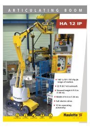
Repair manual2 - PRESENTATION2.1 - TECHNICAL CHARACTERISTICSSelf-propelled platforms, models H14TX and H16TPX, are designed for alltypes of overhead work within the limits of their characteristics (Operatingand maintenance instructions manual) and provided all the safetyrecommendations specific to the equipment and operating environmentare respected.The main control panel is situated in the platform.The control panel situated on the turntable is to be used in emergencies orcases of machine failure.2.1.1 - H14T(X) technical characteristicsDESCRIPTION H14T(X) UnitLoad 230 (2 peoples) KgMax. lateral manual force 400 NMax wind speed 60 Km/hFloor height 12.07 mWorking height 14.07 mOverall length 7.58 mOverall width 2.27 mOverall height 2.20 mWheel base 2.00 mFloor clearance 0.34 mMax bearing distance 10.60 mBoom range -13°/75° °Telescoping (travel) 4.33 mTurntable rotation 360° continu °Reducer (torque) 950Max travel slope4*4 50%Tyre dimensions14 - 17.5 SKS HAULERInterior turning radius 2 mMax allowed tilt 5 °Hydraulic tank 150 lFuel tank 150 lTotal weight4*4 6040KgNumber of drive wheels4*4 4Number of steering wheels 2Differential blockingouiHydraulic brakes 2FreewheelouiTightening torque:- Wheel nuts- Slew ring3201000m.NDEUTZ diesel motor- Power- Idling power- Consumption- Idling consumptionHydraulic pump 45 cm 3 /revF3L1011F38 CH / 28 Kw / 28.33 hp 2400 min-120.4 CH / 15KW / 15.21 hp 1250 min-12309 kwh2309 kwhyes 85 l/min maxi13
Repair manualDESCRIPTION H14T(X) UnitHydraulic pressure:- General- Travel- Steering- SlewTravel speedLow speedMedium speedHigh speedMax. force on one wheel 3100 KgMax pressure on the floor- hard floor (concrete)9500Kg/m²- soft floor (beaten earth)3100Ignition battery12 V - 95 Ah - 450 <strong>AS</strong>upply voltage 104 dBAcoustic power 71.5 dB242424101.63.06.02.1.2 - Technical characteristics H16TP(X)DESCRIPTION H16TP(X) UnitStandart basket1800*800Option basket 2300*800Load 230 (2 peoples) 230 (2 peoples) KgMax. lateral manual force 400 NMax wind speed 45 Km/hFloor height 13.44 mWorking height 15.44 mOverall length 8.47 mOverall width 2.30 mOverall height 2.21 mWheel base 2.00 mFloor clearance 0.34 mMax bearing distance 12.30 mBoom range -1°/+75° °Turntable rotation 360° continu °Max travel slope4*4 50%Tyre dimensions14 - 17.5 SKS HAULERInterior turning radius 2.00 mMax allowed tilt 5 °Hydraulic tank 150 lFuel tank 150 lTotal weight4*4 6800KgNumber of drive wheels4*4 4Number of steering wheels 2Differential blockingyesHydraulic brakes 2FreewheelyesTightening torque:- Wheel nuts- Slew ring3201000m.NMPaKm/h14
Repair manualDESCRIPTION H16TP(X) UnitDEUTZ diesel motor- Power- Idling power- Consumption- Idling consumptionHydraulic pump 45 cm 3 /revHydraulic pressure:- General- Travel- Steering- SlewTravel speedLow speedMedium speedHigh speedF3L1011F38 CH / 28 Kw / 28.33 hp 2400 min-120.4 CH / 15KW / 15.21 hp 1250 min-12309 kwh2309 kwh85 l/min maxiMax. force on one wheel 3596 KgMax pressure on the floor- hard floor (concrete)10500Kg/m²- soft floor (beaten earth)3500Ignition battery12 V-95Ah-450<strong>AS</strong>upply voltage 104 dBAcoustic power 71.5 dB242424101.63.06.0MPaKm/h15
Repair manual2.2 - SIZE2.2.1 - H14T(X) size7586 mm - 24ft 10in1958 mm6ft 5in2204 mm342 mm2000 mm340 mm800 mm2300 mm7ft 6in7ft 2in1ft 1in6ft 6in1ft 1in2ft 7in2278 mm7ft 5in2300 mm7ft 6in16
Repair manual2.2.2 - H16TP(X) size8429 mm - 27ft 7in6712 mm - 22 ft1951 mm6ft 4in2000 mm6ft 6in340mm1ft 1in2204 mm774mm18007ft 2in2528 mm8ft 3in7ft 3in2214 mm96mm3in293 mm11in2ft 6in5ft 10in800mm2ft 7in2300mm x 800mm7ft 6in x 2ft 7in2300mm7ft 6in2278mm2249mm7ft 5in7ft 4inHaulotte2300mm7ft 6in17
Repair manual2.3 - TIGHTENING TORQUE2.3.1 - Tightening torque for large threadTightening torque in N.MNominal diameter8.8 10.9 12.9M 6*1 9 à 11 13 à 14 15 à 17M 7*1 15 à 19 21 à 24 26 à 28M 8*1.25 22 à 27 31 à 34 37 à 41M 10*1.5 43 à 45 61 à 67 73 à 81M 12*1.75 75 à 94 110 à 120 130 à 140M 14*2 120 à 150 170 à 190 200 à 220M 16*2 190 à 230 260 à 290 320 à 350M 18*2.5 260 à 320 360 à 400 440 à 480M 20*2.5 370 à 450 520 à 570 620 à 680M 22*2.5 500 à 620 700 à 770 840 à 930M 24.3*3 630 à 790 890 à 990 1070 à 1180M 27*3 930 à 1150 1300 à 1400 1560 à 1730M 30*3.5 1260 à 1570 1770 à 1960 2200 à 23502.3.2 - Tightening torque for fine threadTightening torque in N.MNominal diameter8.8 10.9 12.9M 8*1 24 à 29 33 à 37 40 à 44M 10*1.25 46 à 57 64 à 71 77 à 85M 12*1.25 83 à 100 120 à 130 140 à 150M 14*1.5 130 à 160 180 à 200 220 à 240M 16*1.5 200 à 250 280 à 310 340 à 370M 18*1.5 290 à 360 410 à 450 490 à 540M 20*1.5 410 à 510 570 à 630 690 à 760M 22*1.5 550 à 680 780 à 870 920 à 1000M 24*1.5 690 à 860 970 à 1070 1160 à 1290M 27*2 1000 à 1300 1400 à 1560 1690 à 1880M 30*2 1400 à 1700 1960 à 2180 2350 à 261018
Repair manual2.3.3 - Pressure table (in bar)GeneratorLoadsensingMainSteerinBrakereleaseRotation Up DownH14/16 23 30 240 240 240 100 240 240TelescopeinTelesopeoutTravel compensation Jib ip Jib downEmergency unitH14/16 110 240 240 240 240 240 1302.3.4 - Table of adjustment timesMovement Control Movement durationHS deceleration From the basket 1,20 m +/- 20cmHS travel forward and reverse From the basket 12s +/- 2s / 20mMicro speed travel From the basket 45s +/- 2s /10mBoom lifting H14 From the basket 48s +/- 2sBoom lifting H16 From the basket 40s +/- 2sBoom lowering H14 From the basket 38s +/- 2sBoom lowering H16 From the basket 30s +/- 2sTelescope out From the basket 30s +/- 2sTelescope in From the basket 25s +/- 2sRotation From the basket 30s +/- 1s per 1/4 turnJib up From the basket 30s +/- 2sJib down From the basket 23s +/- 2sRight/left basket rotation speed From the basket 15s +/- 2sCompensation speed up From the basket 27s +/- 5sCompensation speed down From the basket 35s +/- 5sSteering out From the basket 12sSteering in From the basket 12sBoom lifting H14 From the turntable 48s +/- 2sBoom lifting H16 From the turntable 40s +/- 2sBoom lowering H14 From the turntable 38s +/- 2sBoom lowering H16 From the turntable 30s +/- 2sTelescope out From the turntable 30s +/- 2sTelescope in From the turntable 25s +/- 2sRotation left and right From the turntable 30s +/- 1s per 1/4 turnJib up From the turntable 30s +/- 2sJib down From the turntable 23s +/- 2s19
20Repair manual
Repair manual3 - SAFETY SYSTEM3.1 - MACHINE ELEMENTS3.1.1 - MotorRefG2M3YA2YA1U3DescriptionGeneratorStarterAcceleratorMotor stopFrequency moduleRef3.1.2 - Power supplies and fusesDescriptionFU1 10AMotor stopFU3 80AAcceleratorFU4 30A + MainFU5 3A 212 +TurntableFU6 3A 211 + PlatformFU7 20A201 + ElectrovalvesFU8 5A 242 +PermanentFU9 20A+ AccessoriesFU10 3ALS ValveFU11 250<strong>AS</strong>tandby pump3.1.3 - Control inputsSA2 AcceleratorSA3 Differential blockingSA4Platform basket rotationSA5Platform compensationSA6Turntable jibSA7Platform jibSA8Turntable telescopeSA9SA11LS MS HSSB3Turntable startSB4Platform startSB5BuzzerSA13Turntable liftingSA15Turntable rotationSM31Rotation and liftingSM2 TelescopingSM4Travel21
Repair manual3.1.4 - Safety inputsSQ6 Weight 2nd thresholdSQ5Weight 1st thresholdSQ1TiltSQ2 Jib from 0 to 90°SQ3Boom liftedSQ9Telescope outSQ12 8M breakSQ13 8M breakB4Oil tank temperatureB3Motor oil pressureB1Filter cloggedD+ Generator3.1.5 - Relay outputsKP1KT2KA2Motor stopAcceleratorStarter3.1.6 - On/off electrovalve outputsYV1 LSYV2aPVG TORYV2b PVG TORYV9 Differential blockingYV13 Differential blockingYV8HSYV10MS HSYV12MS HSYV15aCompensation upYV15bCompensation downYV18aJib downYV18bJib upYV19aLeft basket rotationYV19bRight basket rotationYV16a Rear left steering in 4*4YV16b Rear right steering in 4*4YV24Basket rotation \ compensation3.1.7 - Proportional electrovalve outputsYV3 LiftingYV4TelescopingYV5RotationYV6TravelYV7Travel22
Repair manual3.1.8 - BuzzersHA1 HornHA4 Tilt, overload, temperature buzzerHA2Overload 1st threshold buzzer3.1.9 - Light indicatorsHL1 Battery chargeHL2Air filterHL4Motor oil pressureHL9Fault light indicator23
24Repair manual
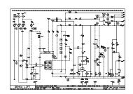
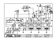
Repair manual4 - WIRING DIAGRAM4.1 - DIAGRAM E 523 - FOLIO 01/051 2 3 4 5 6 7 8 9 10 11 12 13 14 15 16 17 18 19 20A101(02-2)BCFU11FU3FU1250A80A 10ADE120(02-2)FG242242(02-13)GB1HJ(04-20)H P1KB+D+LB-D1 KA43 D2G2~WD4 YA2D3D5YA1MPompe de secours DØmarreurAlternateurEmergency PumpStarterAlternatorAccØlØrateur Stop moteurAcceleratorEngine StopPINGUELY-HAULOTTELa PØronniŁreTEL: 04 77 29 24 24BP 942152 L’HORMEDESSINE PARLaurent DI FLORIOVERIFIE PARFrØdØric DENEZE08-04-1999E523H14T H16TP30-04-1999DATE DE CREATIONDATE DE VERIFICATIONIND DATEMODIFICATIONVISANBRE TOTAL DE FOLIOS5SCHEM<strong>AS</strong>01I87101120101100KM4(02-9)KA2HL1KT2KP1(04-20)(04-19)(04-18)M4 M3108(04-21)(02-2)25
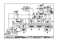
Repair manual4.2 - DIAGRAM E 523 - FOLIO 02/051 2 3 4 5 6 7 8 9 10 11 12 13 14 15 16 17 18 19 20A(01-20)101 120120BKA32C(01-20)FU430AAU TourelleSB1ES TurretKMG(02-10)D215240240E(04-1)SB2 AU NacelleES GantryU1215240 240FT O NF8 F7 F5 F6GSA1FU7 FU8 FU920A 5A 20AH(01-20)242FU5 FU63A 3A212I(03-2)201(03-2)212(03-2)(04-11)211(03-2)(04-13)212JSA19SA20620KKA43(01-12)SA16LHL6MD34KM4KMGHL5HL7(01-20)PINGUELY-HAULOTTELa PØronniŁreTEL: 04 77 29 24 24BP 942152 L’HORME0DESSINE PARDATE DE CREATIONLaurent DI FLORIO 08-04-1999VERIFIE PAR DATE DE VERIFICATIONFrØdØric DENEZE 30-04-19990 00(04-1)Gyrophare Projecteur Voyant mise sous tensionBeacon Spot Light ON / OFF LightIND DATEMODIFICATIONVISANBRE TOTAL DE FOLIOSE5235H14T H16TPSCHEM<strong>AS</strong>0226
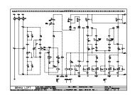
Repair manual4.3 - DIAGRAM E 523 - FOLIO 03/051 2 3 4 5 6 7 8 9 10 11 12 13 14 15 16 17 18 19 20AB242(02-20) (04-1)(02-20)212(05-2)C211211(02-20)(05-2)DSA2 SA3SA4 SA5 SA6 SA7SA11SB3 SB4 SB5E28.7 29.11 30.4 30.3 30.6 30.5 4.6 4.9 30.9 30.8 29.10 29.9 4.12 3.2 29.12FU1AccØlØrateurAcceleratorDifferential LockBlocagediffØrentielGantry RotationRot PanierNacelleGantryCompensationCompensationGantryNacellePendularPendulaireTurretTourellePendularPendulaireNacelleGantryPV MV GVLS MS HSStart upDØmarrageTurretTourelleStat upDØmarrageGantryNacelleKlaxonHornGHPendulairePendularCompensationCompensationPanierGantry RotationSteeringDirection AV/ARRear/FrontMV GVMS HSMS HSMV GVGVHSI18 1917 10 35 34 33 32 8.98.6 8.12 8.11407A408A401A402A310A311A304A306A814A814B813605807311310402401406405410409805804117A117B901JKYV18AYV18B YV15A YV15B YV19A YV19B YV16A YV16B YV10 YV12YV8L4*4M201 201201(02-20) (04-1)PINGUELY-HAULOTTELa PØronniŁreTEL: 04 77 29 24 24BP 942152 L’HORMEDESSINE PARLaurent DI FLORIOVERIFIE PARFrØdØric DENEZE08-04-1999E523H14T H16TP30-04-1999DATE DE CREATIONDATE DE VERIFICATIONIND DATEMODIFICATIONVISANBRE TOTAL DE FOLIOS5SCHEM<strong>AS</strong>0327
Repair manual4.4 - DIAGRAM E 523 - FOLIO 04/051 2 3 4 5 6 7 8 9 10 11 12 13 14 15 16 17 18 19 20A(02-20) 000 0 (05-2)BHA2SQ1(03-20) 242242CD(01-13) (01-11)SQ6 SQ2 SQ3 SQ9M M SQ5EB4 B3 B2 B1FGU130.2 30.1 39.3 3.3 41.2 45.2 43.2 44.2 37.2 36.2 46.2 47.2 42.2 40.2 27.4 27.327.2 27.127.7HI15.9 15.4 20 52.2 52.3 14 4.1 4.24.3807A807B260261J807B807A111ADifferential LockBlocagediffØrentielValve LSLS ValveAvertisseurHornBruiteurBuzzerPression HuileOil PressureTemp HuileOil TempFiltre airFilterStop MoteurEngine StopAccØlØrateurAccØlØratorDØmarrageStart up242WeighingPesage2Łme seuilWeighingPesage1er seuilTilt DetectorDØversPendularPendulaireBoomFlŒcheWTelescopeTelescopeTemp HuileOil TemperaturePression HuileOil PressureOil TempTemp HuileFiltreFilterDplusDplus214111108213(02-20)KYV1YV13 YV9HA1LHA44*4FU10(03-21) 201201(05-2)3AKP1 KT2 KA2HL4 HL3 HL2(02-16)(02-20)242MPINGUELY-HAULOTTELa PØronniŁreTEL: 04 77 29 24 24BP 942152 L’HORMEDESSINE PARLaurent DI FLORIOVERIFIE PARFrØdØric DENEZE08-04-1999E523H14T H16TP30-04-1999DATE DE CREATIONDATE DE VERIFICATIONIND DATEMODIFICATIONVISANBRE TOTAL DE FOLIOS5SCHEM<strong>AS</strong>0428
Repair manual4.5 - DIAGRAM E 523 - FOLIO 05/051 2 3 4 5 6 7 8 9 10 11 12 13 14 15 16 17 18 19 20A(03-20)212212(03-20)211211B(04-21)OCDSM31 SM2 SM4X YHM31 YYHM1HM2SA15 SA8SA13EFU129.1 30.7 30.15 29.4 4.14 4.1530.12 30.14 30.13 29.15 29.2 29.3 29.5 29.6 28.9 28.4 28.2 28.1GHDØfautAlarmTranslationTranslationOrientationOrientationTØlescopeTelescopeRelevageBoomPVG TORConsigneOrientationOrientationConsigneBoomRelevageHors NeutreNull PositionHomme MortDead ManConsigneTelescopeTØlescopeHors NeutreNull PositionHomme MortDead ManTranslationConsigneTranslationHors NeutreNull PositionHomme MortDead ManDirection ARDirection AROrientationOrientationTelescopageTelescopeRelevageBoom512403420A611CI49.2 25.326.3 24.3 23.3 22.3 12.3 12.1 16.2 16.3253698699OJKB AHL9YV7 YV6 YV5 YV4 YV3YV2 TORL4**4O OOM(04-10)201201PINGUELY-HAULOTTELa PØronniŁreTEL: 04 77 29 24 24BP 942152 L’HORMEDESSINE PARLaurent DI FLORIOVERIFIE PARFrØdØric DENEZE20-04-1999E523H14T H16TP30-04-1999DATE DE CREATIONDATE DE VERIFICATIONIND DATEMODIFICATIONVISANBRE TOTAL DE FOLIOS5SCHEM<strong>AS</strong>0529
30Repair manual
Repair manual 1355 - OPERATING INSTRUCTIONS5.1 - START5.2 - STOP MOTOR5.3 - ACCELERATORIf (SB3=1 or SB4=1) and W=0 and D+=0 and YV1=0 then KA2=1By selecting turntable, platform is impossible.If KA2=1 or (mo motor fault for more 6 seconds)* then KP1=1*No motor fault => D+=1 and B2=1 and B3=1If (HM4=1 or HM31=1 or HM2=1 or SA2=1) and SQ6=1 then KT2=15.4 - COMPENSATION5.4.1 - UpIf SA5a=1 and SQ6=1 and SM31ab=0 and SM2ab=0 then YV15a=1 and YetYV1=1YV1 is time delayed for 2 secondsIf SQ6 passes to O during a movement, this one is not cut.5.4.2 - DownIf SA5b=1 and SQ6=1 and SM31ab=0 and SM2ab=0 then YV15b=1 and YV2b=1and YV1=1YV1 is time delayed for 2 secondsIf SQ6 passes to O during a movement, this one is not cut.5.5 - ROTATION5.5.1 - RightIf SA4b=1 and SM31ab=0 and HM31=0 then YV19b=1 and YV2b=1 and YV1=1YV1 is time delayed for 2 seconds5.5.2 - LeftIf SA4a=1 and SM31ab=0 and HM31=0 then YV19a=1 and YV2b=1 and YV1=1YV1 is time delayed for 2 seconds31
135 Repair manual5.6 - JIB5.6.1 - UpIf (SA6b=1 or SA7b=1) and (SQ1=1 or machine folded) and (SQ6=1 or turntableposition)then YV18b=1 and YV2a=1 and YV1=1YV1 is time delayed for 2 secondsmachine folded => SQ2=1 and SQ9=1 and SQ3=1If SQ6 passes to O during a movement, this one is not cut.5.6.2 - DownIf (SA6a=1 or SA7a=1) and (SQ6=1 or turntable position)then YV18a=1 and YV2a=1 and YV1=1YV1 is time delayed for 2 secondsIf SQ6 passes to O during a movement, this one is not cut.5.7 - STEERINGRear Axle5.7.1 - LeftIf SM4d=1 then YV16a=1 and YV2b=1 and YV1=1YV1 is time delayed for 2 seconds5.7.2 - RightIf SM4c=1 then YV16b=1 and YV2b=1 and YV1=1YV1 is time delayed for 2 seconds5.8 - TRANSLATIONLS MV HS MicroSIf SQ2=0 or SQ3=0 or SQ9=0 then MicroS=1If MicroS=0 then NoMicroS=1If SA11a=0 and SA11b=1 and NoMicroS=1 and SM4ab=0 and HM4Ý then LS=1If SA11a=0 and SA11b=0 and NoMicroS=1 and SM4ab=0 and HM4Ý then MV=1If SA11a=1 and SA11b=0 and NoMicroS=1 and SM4ab=0 and HM4Ý then HS=1If NoMicroS=1 and HS=1 then YV8=1 and YV1=1If (HS=1 or MV=1) and NoMicroS=1 then YV12=1 and YV10=1 andYV1=1If SM4ab=1 and HM4=1et (SQ1=1 or machine folded)and SM31ab=0 andSM2ab=0then YV6 and YV7 LS MV HS : Full setpointMicroS : low setpointYV1 is time delayed for 2 secondsIf SQ6 passes to O during a movement, this one is not cut.machine folded => SQ2=1 and SQ3=1 and SQ9=132
Repair manual 1355.9 - TELESCOPING5.9.1 - Turntable5.9.1.1 -OutIf SA8b=1 and (SQ1=1 or machine folded) then YV1=1 and YV4=1YV1 is time delayed for 2 secondsmachine folded => SQ2=1 and SQ9=1 and SQ3=1If SQ6 passes to O the movement is carried more slowly..5.9.1.2 -InIf SA8a=1 then YV1=1 and YV4=1YV1 is time delayed for 2 secondsIf SQ6 passes to O the movement is carried more slowly..5.9.2 - Platform5.9.2.1 -OutIf SM2ab=1 and SQ6=1 and HM2=1 and (SQ1=1 or machine folded) then YV1=1and YV4=1YV1 is time delayed for 2 secondsmachine folded => SQ2=1 and SQ9=1 and SQ3=1If SQ6 passes to O during a movement, this one is not cut.5.9.2.2 -InIf SM2ab=1 and SQ6=1 and HM2=1 then YV1=1 and YV4=1YV1 is time delayed for 2 secondsIf SQ6 passes to O during a movement, this one is not cut.5.10 - ROTATION5.10.1 -Turntable5.10.1.1 -LeftIf SA15a=1 then YV1=1 and YV5=1YV1 is time delayed for 2 secondsIf SQ6 passes to O the movement is carried more slowly.5.10.1.2 -RightIf SA15b=1 then YV1=1 and YV5=1YV1 is time delayed for 2 secondsIf SQ6 passes to O the movement is carried more slowly.33
135 Repair manual5.10.2 -Platform5.10.2.1 -LeftIf SM31ab=1 and SQ6=1 and HM31=1then YV1=1 and YV5=1YV1 is time delayed for 2 secondsIf SQ6 passes to O during a movement, this one is not cut.5.10.2.2 -RightIf SM31ab=1 and SQ6=1 and HM31=1then YV1=1 and YV5=1YV1 is time delayed for 2 secondsIf SQ6 passes to O during a movement, this one is not cut.5.11 - LIFTING5.11.1 -Turntable5.11.1.1 -UpIf SA13a=1 and (SQ1=1 or machine folded or SQ9=1) then YV1=1 and YV3=1YV1 is time delayed for 2 secondsmachine folded => SQ2=1 and SQ9=1 and SQ3=1If SQ6 passes to O the movement is carried more slowly.5.11.1.2 -DownIf SA13b=1 and (SQ1=1 or machine folded or SQ9=1) then YV1=1 and YV3=1YV1 is time delayed for 2 secondsIf SQ6 passes to O the movement is carried more slowly.5.11.2 -Platform5.11.2.1 -UpIf SM31ab=1 and SQ6=1 and HM31=1 and (SQ1=1 or machine folded or SQ9=1)then YV1=1 and YV3=1YV1 is time delayed for 2 secondsmachine folded => SQ2=1 and SQ9=1 and SQ3=1If SQ6 passes to O during a movement, this one is not cut.5.11.2.2 -DownIf SM31ab=1 and SQ6=1 and HM31=1 and (SQ1=1 or machine folded or SQ9=1)then YV1=1 and YV3=1YV1 is time delayed for 2 secondsIf SQ6 passes to O during a movement, this one is not cut.34
Repair manual 1355.12 - DIFFERENTIAL BLOCKINGIf SA3=1 and SA11a=0 and HS=0 then YV9=1 and YV13=15.13 - GENERATORIf SQ11 = 1 and Platform position and KA2 = 0 and D+ = 1 then YV24 = 1The generator functions only if the machine is in turntable position, if the thermalengine turns and if the operator engaged the button located in the platform. In thiscase the green indicator is light.Dans ce cas le voyant vert est allumé.SAFETY AT START :If the button is in ON position, during all the phase of start, the generator and theaccelerator are cut. Once this phase finished the generator is automatically givenin service.5.14 - HORNIf SB5=1 then HA1=15.15 - BUZZERIf SQ1=0 and machine unfolded then the buzzer sounds continuously.If B4=0 then the buzzer sounds with a frequency F1.If SQ6=0 and turntable position then the buzzer sounds with a frequency F1.If travel_Buzzer_option=1 and HM4=1then the buzzer sounds with a frequency F2.If movements are carried out (YV1=1 or SA4a=1 or SA4b=1) andmovement_Buzzer_option = 1 then the buzzer sounds with a frequency F2.Machine unfolded => SQ2=0 or SQ9=0 or SQ3=05.16 - HL2If B1=0 then HL2=15.17 - HL4If B3=0 then HL4=135
135 Repair manual5.18 - OTHER FUNCTIONS: OVERLOAD, SAFETY…5.18.1 -OverloadThe overload through SQ6 cuts all the ordered movements of the platform. Whenone passes in turntable position, one recovers the movements with a limitedspeed. Moreover the turntable buzzer sounds.5.18.2 -Fuse safetyIf an electrovalve is controlled permanently for any reason (short-circuitedelectrovalve, etc ...) fuse FU7 is destroyed.The emergency stop is relayed. For any reasons, we must constantly monotorthat the relay does not remain stuck after an emergency stop.5.18.3 -Fail-safeIf the fail-safe is held for 10 seconds (Controller or neutral), movement is devalidated..x = 6s for travelx = 4s for movements5.18.4 -Indicator defectIf SQ6=0 or (SA8a=1 or SA8b=1 or (HM2=1 and SM2ab=1))or (SA13a=1 or SA13b=1 or (HM31=1 and SM1ab=1)))then HL9=136
Repair manual 1356 - POSITIONS OF ELECTRIC COMPONENTS6.1 - MOTHER BOARD6.1.1 - DescriptionRef SCREW Ref Connector1 101 + Battery 28 1 Flashing light2 105 + Bi-energy machine - option 29 2 Bottom box door3 120 + Main 30 3 Top control panel4 103 Starter 31 4 Bottom box door5 118 Accelerator control 32 55 KMG main relay6 240 Main supply after switch 33 5 KM4 standby pump switch7 102 Emergency stop circuit 34 6 Console connector8 215 Emergency stop circuit 35 52 HA1 horn9 0 - Battery 36 7 Gas electrovalves option10 226 Petrol gas machine - option 37 54 Proportional valve output11 224 Petrol gas machine - option 38 14 BuzzerRELAYS 39 47 SQ1312 KA2 Start 40 22 Boom lifting PVG13 KP1 Motor stop 41 23 Telescoping or arm lifting PVG14 KA32 Electric power / thermal power switch 42 24 Rotation PVG15 KT2 Accelerator 43 25 Travel PVG16 KA43 Standby pump safety system 44 26 Travel PVG17 KA37 Converter for bi-energy machine 45 27 Motor wiring harness18 KA46 Petrol / gas switch 46 28 Top control panelFUSES 47 29 Top control panel19 F1 Motor stop 48 30 Top control panel20 F3 Maintain accelerator 49 36 SQ1121 F4 Main 50 37 SQ1022 F5 + Bottom position 51 39 SQ6 Tilt23 F6 + Top position 52 40 Hydraulic tank temperature probe B424 F7 + Electrovalve 53 41 SQ325 F8 + Permanent (sensor supply) 54 42 SQ4 or SQ1426 F9 + Accessories 55 43 SQ727 F10 + Load Sensing valve for machine with 56 44 SQ8PVG57 45 SQ937
135 Repair manual6.1.2 - Positions of screws, connectors and relays14 1 2 3 4 5 28 29 6 7 8 9 3017101531123618111332 33 16 34 3537383947484041424344495045465152535455565738
Repair manual 1356.1.3 - Positions of fuses2019 21 22 26 27 25 23 2439
135 Repair manual6.1.4 - Positions of diagnosis help LEDsYV20YV9YV18BYV18AYV15BYV15AYV21BYV21AYV13AYV22BYV2AYV11YV10YV2BYV12YV8YV23YV14BYV14AYV22AYV1YV16B YV16A YV19B YV19A40
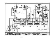
Repair manual7 - HYDRAULIC DIAGRAMS7.1 - DIAGRAM H14T(X) REFERENCE B16007M3 1" M1 3/4" M2 3/4" B2 3/4" A2 3/4" A3 3/4" B3 3/4"YV9A B43PT224,6L1,58L14,3L1,65L1,19L1,24L5,7L111/2"1/2"1/2"1/2"8,6L121/2"1 3P1 1/2" B1 1/2"P2 1/2" A1 1/2" Fr1 1/4"101 2 3 4 78YV16b YV19aYV19b YV15a YV15bA BA B9765 65324DIRECTIONSTEERING1413151621233121/4"1/4"1/4"1/4"YV12YV13A BA BYV8A BC1200 b2 4YV10A B1 3P T1 33/4" 3/4" 3/4" 3/4" 1/4"YV1 YV6 YV7 YV8 YV12YV10A 3/8"B 3/8"PVA B1/4" 1/4"M22x1,50,5L3/8"OMM 3/8"3/8"3/8"1/4" 1/4"123321433122PP34TT212PTPTPT140 bV1 1/2" V2 1/2"100 b100 bYV7 YV6 YV5YV4 YV3 YV2YV16aA 3/8"B 3/8"A 3/8"B 3/8"270 bYV1T 3/4" P 3/4" TRANSLATION TRANSLATION ORIENTATION TELESCOPAGE RELEVAGE MOUVEMENTSFLECHE TOUT OU RIENM22x1,53/4"3/8"3/4"0,6L3/8"240 bM14x1,53/8"3cm33/8"M18x1,5L1 L7/8-14UNF1"1/2 3/4"1" 3/8"1/4"1/4"1/4"1/4"PTEMETTEURM<strong>AS</strong>TERRELEVAGE FLECHEBOOMTRANSLATIONTRANSLATIONESSIEU DIRECTEUR ESSIEU MOTEURSTEERING AXLE MOTOR AXLEOMSS801/2" 1/2"OMSS 1/2"801/2"OMSS 1/2"80OMSS80ORIENTATIONTURNTABLE ROTATEMSR100TELESCOPAGEBOOM EXTENSIONRECEPTEURSLAVEC1200 bV1 3/8" V2 3/8"Fr21/4"Dr1/4"MVGV1/2" 1/2" 1/2" 1/2" 1/2" 1/2" 1/2" 1/2" 1/2" 1/2" 1/2" 1/2"1/2"1/2"32MPTTIROIR 10 LSPOOL 10 L1/4"LS1/4"7/16-20UNF1"5/16-12UNFMBSAXBABABABABABCOMPENSATIONPLATFORM LEVEL45cm3maxi28kW 12V2400tr/min1"7/8-12UNFROTATION PANIERPLATFORM ROTATETIROIR 65 LSPOOL 65 LTIROIR 65 LSPOOL 65 LTIROIR 10 LSPOOL 10 LTIROIR 65 LSPOOL 65 LTIROIR 5 LSPOOL 5 LMB16007d41
Repair manual7.2 - DIAGRAM H16TP(X) REFERENCE 16009oB16009d42
Repair manual8 - MAINTENANCE8.1 - GENERAL RECOMMENDATIONSServicing operation described in this manual are given for normalconditions of use.In difficult conditions: extreme temperatures, high hygrometry, pollutedatmosphere, high altitude, etc ..., certains operations must be carried outmore frequently and specific precautions must be taken: consultPINGUELY HAULOTTE After-Sales Service for information.Only authorised and competent personel may operate on the machine andmust comply with the safety instructions related to Personnel andEnvironment protection..As far as the motor is concerned, refer to the manufacturer's manual andinstructions.Attention !- Do not use the machine as awelding earth.- Do not weld withoutdisconnecting the (+) and (-)terminals of the batteries.- Do not start other vehicles with thebatteries connected.For the motor part, consult the instructions in the Manufacturer’s manual.Safety mechanisms should be checked regularly:• Tilt: buzzer and movements disabled.Buzzer: load between 100% and 110% of permitted load.Movements disabled: Load above 110% of permitted load.• Change to micro-speed when the machine is unfolded.8.2 - PARTICULAR RECOMMENDATIONSBefore any maintenance intervention on the elevating platform, indicate onthe turntable and platform control stations that the machine is beingserviced. If possible, restrict access to the elevating platform to interventionpersonnel only.8.2.1 - Specific toolsPersonnel should therefore be familiar with the use of the specific toolsused (measurement device, torque tightening device, lifting apparatus,etc.) and respect the operating limits specified in the documentation that issupplied with the tools.Incorrect use of a tool (incorrect adjustment after a reading error) may leadto premature deterioration of the elevating platform (or more seriously, anaccident), for which PINGUELY-HAULOTTE cannot be held responsible.8.2.2 - Replacing an elementBefore replacing an element, the machine must be put in the maintenanceconfiguration (see chap. 8.3, page 38) and the electric power supply cutoff (see chap. 8.4, page 45).All distributing valves are "with open centre": breaking the electric circuittherefore decreases pressure in the hydraulic circuits, up to the non-returnvalves flanged on the cylinders. An element can be replaced safely, if theprocedures described in the maintenance sheets are respected (unscrewhydraulic connectors slowly to release residual pressure).43
Repair manualTo preserve the integrity of the safety systems and the technicalcharacteristics of the elevating platform, it is essential to use original partsand to respect the initial setting and tightening torque values (see Chapitre2, page 11).8.2.3 - Locating the breakdownCertain checks require the elevating platform to be switched on. In thiscase, personnel must ensure:• that the measurement devices used are properly insulated,• that they do not touch the live parts,• that they are not wearing or carrying metal objects that may deterioratethe live components (e.g.: dropping a spanner during an interventionon the batteries).8.3 - MAINTENANCE SYSTEMPhoto 111InstructionsMaintenance configuration:• Position the elevating platform on a firm, horizontal surface.• If possible, fold the machine completely.• Put the turntable rotation blocking pin into place (ref. 1 Photo. 1,page 44).Restoring operational configuration:Remove the blocking pin (ref. 1 Photo. 1, page 44).44
Repair manual8.4 - ELECTRIC POWER SUPPLYPhoto 2 .InstructionsCutting off the electric power supplyPress the turntable emergency stop (ref. 1 Photo. 2, page 45).Restoring the electric power supply:Reset the emergency stop (ref. 1 Photo. 2, page 45).145
Repair manual8.5 - MAINTENANCE PLANThe plan shows the frequency and area of maintenance and theconsumables to be used.The reference shown in the symbol shows the area maintained based onthe frequency.The symbol represents the consumable to use (or the operation to becarried out.•8.5.1 - ConsumableConsumable Specification Symbol Lubricants used byPinguely-HaulotteMotor oilSAE 15W40SHELLRIMULA-XGearbox oil SAE 90Hydraulic oilAFNOR 48602ISO VG 46SHELLSPIRAX-AEP80W-90SHELLTELLUS T46ELFTranselfEP 80 W 90HYDRELFDS 46TOTALTM 80 W/90EQUIVISZS 46Optional bio-degradablehydraulic oilEF-E 46SHELLLithium greaseKP 2 KESSOBeacon EP2Epaxa 2Lithium greaseNLGI 2 EPESSO MolyMulti-Purpose GreaseCadrexaGR1 ALLead-free grease Grade 2 ou 3ESSOGP GRE<strong>AS</strong>EMultimotive 2MultisEP 2Exchange or specificoperation46
Repair manualHours1650329 12 19 1012 92325262517 1821141510502505002729 28301 0002 0007 5 1 4 612 912 9 17 1810502520 11242525050047
Repair manual8.6 - OPERATIONS8.6.1 - Summary table.Frequency Ref. OperationEvery day or beforeeach start ofoperationsThe first 50 hours 9123456710Every 50 hours 1112141516171819Every 250 hours 202123Every 500 hours 242526Every 1000 hours 11or every year27Every 2000 hours 282930Every 3000 hoursCheck the following levels• motor oil• hydraulic oil,• diesel.• electric batteries.Check the cleanliness• disel pre-filter, replace it if water or impurities are found.• motor air filter.• machine (in particular, check the tightness of connections and hoses), usethe opportunity to check the condition of the tyres, cables and all accessoriesand equipment.Check the hydrualic oil filter for clogging.Change the cartridge if the clogging indicator is visible.Check the state of wear of the articulation axles.Change the hydraulic oil filter cartridge (see frequency 250 hours).Change the oil of the drive wheel reducers (see frequency 500 hours) (2 points for4x2 model - 4 points for 4x4 model).Check the tightness of the slew ring screws (torque 10 daN.m).Motor: see manufacturer’s manual.Check the level of the drive wheel reducers (see section 5.3.2.2).Grease:• jib articulation axle (for HB44J): 2 points.• basket link part articulation axle: 4 points.• boom base axle: 1 point.• wheel pivot pin axles: 8 points.• steering axle, central pivot pin and clevis pin: 10 points.• slew ring: bearing 2 points.Motor: see manufacturer’s manual.Grease the friction parts of the telescope (spatula). At the same time, check thecondition of the friction pads.Check the tightness of the wheel nuts (torque 32 daN.m).Change the hydraulic filter cartridge.Motor: see manufacturer’s manual.Change the wheel reducer oil. Fill up (capacity 4 x 1.4 litres.for 4*4 and capacity2 x 1.4 litres for 4*2).Ring screws check the tightness and tighten if necessary. (torque 10 daN.m).Motor: see manufacturer’s manual.Empty the hydraulic oil tank.Empty the tank and the whole hydraulic oil circuit.Empty and clean the diesel tank.Grease the rotation reducer: 1 point.Check the condition of the telescope friction pads, the electric cables andhydraulic hoses.REMINDER:The frequencies given above are to be reduced in the case ofwork in difficult conditions (consult the After-Sales departmentif necessary).48
Repair manual8.7 - PRESENCE OF LABELSIt is important to check that the labels and plates warning personnel of thevarious dangers associated with using the machine are in good condition.The labels providing operators with information on machine use andmaintenance must also be checked.An illegible label may lead to incorrect or dangerous use of the machine.Operating instructions:Check the presence of the labels:Check that all the labels described below are legible and in the correctplace. Replace if necessary (spare parts can be supplied on request, ifnecessary).8.7.1 - Label referencesRef Code Qty Description2 3078148220 2 H14TX logo2 3078148210 2 H16TPX logo5 3078146020 2 H14TX floor height + load5 3078149210 2 H16TPX floor height + load7 3078143450 1 Operating instructions8 3078143270 1 Manufacturer’s plate9 3078144130 2 Do not park in the work area10 3078144140 1 Danger of electrocution11 3078143520 1 Hydraulic oil12 3078145070 1 Danger, travel direction13 3078143590 1 Oil level17 3078143640 1 Do not stand on the cover19 3078143600 2 Do not use as an earth20 3078143540a 1 Socket 220V21 3078143680b 1 Read operating manual30 2420505950 1 Warranty activation31 3078145180 1 Do not exchange33 3078144490 4 Sling load capacity for Australia34 3078144510 1 Fuel tank filling for Australia40 2421808660 1 Yellow and black reflective adhesive marking41 3078143570 1 Greasing the slew ring42 3078143530 1 Remove the pin44 3078143630 2 Danger of body crushing47 3078146480 2 Vertical H16TP logo48 3078143930 1 Green arrow49 3078143940 1 Red arrow50 3078148770 1 Haulotte logo52 3078144530 1 Emergency operation for Australia53 3078144520 2 Harness load for Australia54 3078148970 2 Large size Haulotte logo55 3078148410 1 Manual trouble-shooting56 3078144930 1 Basket load conform to standard EN280 for Australia14 3078143620 2 Risk of injury to hand and fingers51 3078148700 1 Acoustic power11 3078148890 1 Biodegradable oil in option49
Repair manualRef Code Qty Description57 307P202360 1 Motor support rotation29 3078145730 1 220 V socket for Holland only24 3078145580 1 Platform control panel label23 3078145570 1 Turntable control panel label27 1 Operating and servicing manual28 1 Parts manual7 3078144560 1 Diesel operating instructions for Australia10 3078144430 1 Danger of electrocution for Australia60 3078149240 2 Do not spray water near the built-in generator61 3078150500 1 Built-in generator ON button48 3078145210 1 White arrow Australia49 3078145220 1 Black arrow Australia12 3078145230 1 Danger: Direction of movement Australia59 3078145200 1 Pressurised fluid for Australia24 307P203630 1 Platform control panel23 307P203640 1 Ground control panel50
Repair manual8.7.2 - Common "red" labels10 123.F.GB.DComposant spØcifique cette machine.NE P<strong>AS</strong> INTERCHANGER.Component specificto this machine.DO NOT INTERCHANGE.Komponenten nur frdiese maschine geeignet.BITTE AUF EINE ANDEREM<strong>AS</strong>CHINE NIGHTMONTIEREN.N MACHINE - M<strong>AS</strong>CHINE N7814 5189 44145551
Repair manual8.7.3 - Common "yellow" labels19 17 4241 20 57a52
7814-3947814-393(H16TPX)a b c dRepair manual8.7.4 - Various common labels7494851 1111132155b c da(H16TPX)(H16TPX)7814 841a b c d53
Repair manual8.7.5 - Labels specific to Australia56 523331248 49WARNINGIF DIRECTION OF TRAVEL ISOBSCURED, ROTATE UNITTHROUGH 180 DEGREES ANDNOTE COLOUR OF DIRECTIONOF TRAVEL ARROWS ON THECH<strong>AS</strong>SIS IN RELATION TOTRAVEL CONTROL JOYSTICKARROWS7814 52359WARNINGThis accumulator containspressurissed oil. Care must be takenwhilst carrying out maintenance onthis component.77814 5217814 5227814 5205310DANGERBEWARE OF OVERHEAD ELECTRICAL HAZARDSREGULATION 133A of the CONSTRUCTION SAFETY ACT 1912 REQUIRESa. Minimum approach of an applianceto live electrical apparatus.3 m for voltages up to 132,0006 m for voltages above 132,000and up to 330,0008 m for voltages above 330,000b. Inspection of the work site forelectrical hazards beforecommencing to use the appliance.c. Constant vigilance and an observer required whilst working ortravelling the appliance in the vicinity of live electrical apparatus.54
Repair manual8.7.6 - Labels specific to Holland297814 573 a8.7.7 - Built-in generator in option60 6155
Repair manual24 2356
Repair manual8.7.8 - Label positioning60301050D16561 c573349953 56 61445452291914483371419 31174233235525184744415Option machine20 1224 521 27 286140341113933Machines standardSupplément machines HollandeSupplément machines Australie57
58Repair manual
Repair manual 1359 - PREVENTIVE MAINTENANCE SHEETSList of preventive maintenance sheetSheet no.P005P006P007DescriptionChecking - filling the hydraulic oil tankReplacing the hydraulic filter cartridgeChecking - changing the oilof a wheel reducing gear59
60135 Repair manual
Sheet P005PREVENTIVE MAINTENANCE SHEETCHECKING - FILLINGTHE HYDRAULIC OIL TANKFolio 1/11 - Preliminary operations• Put the machine in the maintenance configuration (see § 6.3, page 32).• Switch off electric power (see § 6.4, page 32).2 - Checking - filling the hydraulic oil tankNB:This operation must be carried out when the oil is cold, i.e. before startingthe machine.• Check that the level of oil (1) in the tank is between the high and low levelswhen cold.• Top up if necessary, by filling via the cap (2).NB:Only use the oil recommended by the manufacturer.• Put the machine back into the operational configuration.21HA16/18PX - HA46/51JRT21HA16/18PX New DesignHA46/51JRT
PREVENTIVE MAINTENANCE SHEETSheet P006CHANGING THE HYDRAULIC FILTERFolio 1/1CARTRIDGECaution!Use a container to collect oilto prevent pollution of theenvironment.22 - Preliminary operations• Put the machine in the maintenance configuration (see § 6.3, page 32).• Switch off electric power (see § 6.4, page 32).2 - Replacing the hydraulic filter cartridgeNB:The filter has a clogging indicator. Clogging should be checked whenthe machine is hot, otherwise, the indicator may be visible due to theviscosity of the cold oil.• Change the cartridge (1) if the clogging indicator appears (2).• Unscrew the base nut (3) and remove the cartridge from the hydraulic filter.• Screw a new cartridge into place.• Put the machine back into the operational configuration.13HA16/18 PXHA46/51JRTHA20/26 PXHA61/80JRT213H14P / H16TPHB40/44J
PREVENTIVE MAINTENANCE SHEET
PREVENTIVE MAINTENANCE SHEETSheet P007CHECKING - CHANGING THE OILFolio 1/1OF A WHEEL REDUCING GEARCaution!Use a container to collect oilto prevent pollution of theenvironment.Caution!Make sure that the machineis properly stabilised, andthat the lifting means are ingood condition and ofsufficient capacity.3 - Preliminary operations• Put the machine in the maintenance configuration (see § 6.3, page 32).• Switch off electric power (see § 6.4, page 32).2 - Checking the level• Turn the wheel so that one cap (1) is on a horizontal line and the other (2) ison a vertical line.• Unscrew the cap (1) and check the level that should be up to the hole. Top upif necessary.• Screw the cap back into place.NB:Only use the oil recommended by the manufacturer.3 - Changing the oil• In the same position, unscrew the 2 caps and let the oil flow out.• Re-fill as described above.• Screw the caps back into place.NB:Collect old oil to prevent pollution of the environment.4 - Additional operations• Put the machine back into the operational configuration.HA16/18PX - HA46/51JRTHA20/26 PX - HA61/80JRTH14T(X) - H16TP(X)HB40/44J
PREVENTIVE MAINTENANCE SHEET
Repair manual10 - OPERATING INCIDENTS10.1 - INCIDENT TABLEBefore diagnosing a failure, check that:• the fuel tank is not empty,• the batteries are properly charged,• the turntable and platform "palm button" emergency stop buttons areunlocked,• the relays (platform control panel - turntable box) are correctly pushedinto their compartments, (see § 4.2, page 26).• the main tank oil level is OK,• the state of the fuses, (see § 4.2, page 26).• the electrovalves are working properly by checking the state of theLEDs in the turntable box.Check the state of the LEDs (see § 4.2, page 26):The LEDs inside the turntable box indicate the state of the electrovalves:• LED off: electrovalve present and not controlled,• LED on: electrovalve present and controlled.NB:If an electrovalve is not connected, the corresponding LED ispermanently on.Instructions:• Identify the defective function.• Machine power on but not started: check the presence of the electrovalves(LED off).• No electrovalve should be controlled (LED on).• Check that the outputs corresponding to the function are active usingthe LEDs and directly on the electrovalve heads.• If they are not active, check which inputs create the function.• Test the inputs with a voltmeter.67
Repair manual10.1.1 -General operationANOMALY PROBABLE CAUSE SOLUTIONThe motor does not start, thestarter is activatedThe motor does not start, thestarter is not activatedThe motor starts, then stopsafter 5s.The motor does not startfrom the platform station butdoes start from the turntablestationThe motor does not startfrom the turntable station butdoes start from the platformstationNo motor acceleration regardlessof the movement controlledfrom the platformNo motor acceleration byactivating the acceleratorswitch SA2 on the turntablecontrol stationNo movement available (fromturntable or platform station)• Diesel tank empty• Fuse FU1 defective• Diesel supply circuit defective• Wiring defective• Module U1 defective• Stop motor solenoid YA1 defective• Emergency stop locked• Generator defective• Batteries defective• Fuses FU1, FU4 or FU8 defective• Wiring defective• Switch SB3 or SB4 defective• Relay KA2 defective• Diesel tank empty• Diesel supply circuit defective• Fuse FU6 defective• Defective connection of switch SB4• Switch SB4 defective• Wiring harness defective• Switch SB3 defective• Wiring harness defective• Electronic module U1 defective• Wiring harness defective• Fuse FU3 defective• Relay KT2 defective• Electronic module U1 defective• Wiring harness defective• Accelerator switch SA2 defective• Motor accelerator coil YA2 defective• Insufficient hydraulic oil• Fuse FU7 or FU4 or FU10 defective• Wiring harness defective• Electrovalve YV1 defective• Incorrect "Load sensing" pressure setting• Motor-pump coupling defective• Hydraulic pump defective• Pressure limiter defective• Distribution block input module defective• Pump regulation unit incorrectly set or defective• Hydraulic pump defective• Electronic module U1 defective• Relay KMG defective• Printed circuit defective• Key switch SA1 defectiveFiche DP015Fiche DP016Fiche DP041Fiche DP019Fiche DP020Fiche DP021Fiche DP022Fiche DP02368
Repair manualNo movement available fromthe platform control stationNoisy hydraulic pumpInsufficient pressure orpower at the pumpNo travel telescope out,boom and arm lifting, + buzzersoundingBuzzer soundingThe electropump does notwork• Fuse FU1 defective• Platform control station defective• Fail-safe pedal defective• Wiring harness defective• Oil non-conform• Obstruction of the tank air vent• Suction valves closed• Defective pipes• Hydraulic pump defective• Insufficient oil level• Clogged air filter• Motor speed too low• Oil leak on connector, hose or component• Clogged oil filter• Slope or tilt >5°• Slope or tilt > 5°• Platform load close to cut-off• Hydraulic oil temperature too high• Battery breaker open• Fuses broken• Defective or discharged batteries• The battery wires do not make contactFiche DP024Fiche DP025• Change the filter• Adjust speed• Repair or replace• Replace oil filter cartridge• First retract the telescope andlower the boom to reset• Reset by retracting the telescopeand lowering the boom• Remove load• Leave to cool• Close the battery breaker• Replace the fuses• Replace or recharge the batteries• Clean or tighten the terminals69
Repair manual10.1.2 -Lifting systemANOMALY PROBABLE CAUSE SOLUTIONNo platform up and/or downcompensation movementNo platform right and/or leftrotation movementNo jib movement (up and / ordown) from the platform (orturntable) control stationNo telescoping movement(out and/or in) from the platform(or turntable) controlstationNo boom lifting movement(up and/or down) from theplatform (or turntable) controlstationThe arms and boom do notmove up• Electrovalve YV15 or YV2 defective• Coil defective• Electronic module U1 defective• Wiring harness defective• Printed circuit defective• Compensation switch SA5 defective• Lifting manipulator defective• Electrovalve YV19 or YV2 defective• Coil defective• Electronic module U1 defective• Wiring harness defective• Printed circuit defective• Basket rotation swtich SA4 defective• Electrovalve YV18 or YV2 defective• Coil defective• Electronic module U1 defective• Wiring harness defective• Printed circuit defective• Flow limiter defective• Jib switch SA7 or SA6 defective• Electrovalve YV14 or YV2 defective• Coil defective• Electronic module U1 defective• Wiring harness defective• Printed circuit defective• Telescoping switch SA9 or SA8 defective• Pressure limiter defective• Electrovalve YV3 defective• Electronic module U1 defective• Wiring harness defective• Printed circuit defective• Lifting switch SA13 defective• Lifting manipulator SM31 defective• Battery discharged by more than 80%• Charge check device defectiveFiche DP026Fiche DP027Fiche DP028Fiche DP072Fiche DP030• Change the batteries• Replace the charge checkdevice70
Repair manual10.1.3 -Travel systemANOMALY PROBABLE CAUSE SOLUTIONNo machine travel movementOnly travel micro-speedremains available on themachine, regardless of thespeed selectedMachine travel speed doesnot correspond to the selectorSudden stop of travel duringa platform lifting operationNo differential blockingduring action on switch SA3• Connectors disconnected• Manipulator HM4 defective• Wiring harness defective• Electronic module U1 defective• Coils of electrovalve YV6 or YV7 defective• Electrovalves YV6 or YV7 defectives• Machine unfolded• Contactors SQ2, SQ3, SQ4 incorrectly setor defective• Wiring harness defective• Electronic module U1 defective• Printed circuit defective• Electrovalve YV8, YV10, YV12 orYV17defective• Coil of electrovalve YV8, YV10 or YV12 defective• Wiring harness defective• Printed circuit defective• Speed selector SA11 defective• Electronic module U1 defective• Contactors SQ3, SQ4, SQ2 incorrectly setor defective• Wiring harness defective• Electronic module U1 defective• Switch SA3 or SA11 defective• Electronic module U1 defective• Wiring harness defective• Contactors SQ3, SQ9, SQ2 incorrectly setor defective• Printed circuit defective• Coils of electrovalves YV9 or YV13defective• Electrovalves YV9 or YV13 defectiveFiche DP032Fiche DP056Fiche DP034Fiche DP058Fiche DP036No grip on a drive wheel • Insufficient load on one wheel • Act on the blocking button71
Repair manual10.1.4 -Steering systemANOMALY PROBABLE CAUSE SOLUTIONNo steering movement (rightand/or left) on the rear axle• Electrovalve YV16 or YV2 defective• Coil defective• Electronic module U1 defective• Wiring harness defective• Printed circuit defective• Travel switch SM4 defectiveFiche DP06010.1.5 -Turntable rotation systemANOMALY PROBABLE CAUSE SOLUTIONNo turntable rotation movement(right and/or left) fromthe platform (or turntable)control stationThe turntable does not turn• Electrovalve YV5 defective• Electronic module U1 defective• Wiring harness defective• Printed circuit defective• Rotation switch SA15 defective• Rotation manipulator SM31 defective• The blocking pin has not been removedfrom the chassisSheet DP018• Remove the pinNB:In the turntable box, LEDs indicate the state of each output sothat you can check if an output is activated.10.2 - BREAKDOWN DETECTION FLOW CHART72
Sheet DP015BREAKDOWN DETECTION FLOW CHARTThe motor does not start,the starter is activatedTHE MOTOR DOES NOT START,THE STARTER IS ACTIVATEDFolio 1/2Check the level of the dieseltankDiesel OKNOFill the diesel tankYESOpen the turntable control paneland check the state of fuse FU1ENDFuseOKNOReplace fuse FU1YESCheck the diesel supply circuitSee motor manufacturer manualENDCircuitOKNOYESActivate the starter switch SB3 orSB4 and check for 12V betweenterminals 242 and 150 of the turntablecontrol boxRepair diesel supply circuit Seemotor manufacturermanualEND12V OKNOYESBA
Sheet DP015BREAKDOWN DETECTION FLOW CHARTTHE MOTOR DOES NOT START,THE STARTER IS ACTIVATEDFolio 2/2ABReplace relayKP1See FicheC062Check wiring between the motor starterswitch SB3 or SB4 and the printed circuitof the turntable control boxThe faultpersistsNOYESENDNOWiringOKCheck continuity of the electricwiring harness between relay KP1(terminal 115 of the turntable box)and motor stop solenoid YA1Repair wiringENDContinuityOKNOReplace module U1See FicheC058YESReplace the defectivewiring harnessENDReplace the motor stop solenoidYA1ENDEND
Sheet DP016BREAKDOWN DETECTION FLOW CHARTTHE MOTOR DOES NOT START,THE STARTER IS NOT ACTIVATEDFolio 1/3The motor does not start,the starter is not activatedCheck the position of the platform andturntable emergency stop buttonsPositionunlockedYESNOUnlock the emergency stop buttonCheck the state of battery chargeENDBatterychargeOKNOYESACharge the batteriesCheck the state of the generatorand replace if necessaryThe batteries arechargingNOENDENDYESReplace the batteriesSee SheetC046END
Sheet DP016BREAKDOWN DETECTION FLOW CHARTTHE MOTOR DOES NOT START,THE STARTER IS NOT ACTIVATEDFolio 2/3AOpen the turntable control panel andcheck the state of fuses FU1, FU4and FU8Fuses OKNOYESCheck the 12V on line 242 of theturntable control panelReplace the defective fuseEND12VOKNOYESActivate switch SB3 (turntable)or SB4 (platform) and checkcontinuity between the 2 switchterminalsRepair key switch SA1 wiringor replace the switchENDContinuityOKNOBYESReplace the defectiveswitchSee FicheC044END
Sheet DP016BREAKDOWN DETECTION FLOW CHARTTHE MOTOR DOES NOT START,THE STARTER IS NOT ACTIVATEDFolio 3/3BActivate the starter switch SB3 or SB4 andcheck for 12 V voltage between terminals242 and 146 in the turntable control box12VOKNOReplace the relayKA2YESSee FicheC062Check wiring between switchSB3 or SB4 and the turntablecontrol boxNOThe faultpersistsENDYESCheck continuity of the electricwiring harness between relay KA2(terminal 103 of the turntable box)and the starter solenoidContinuityOKNOYESReplace the starterReplace the defectiveelectric wiring harnessENDEND
Sheet DP018BREAKDOWN DETECTION FLOW CHARTNO TURNTABLE ROTATION MOVEMENT(RIGHT AND / OR LEFT) FROM THE PLATFORM(OR TURNTABLE) CONTROL PANELNo turntable rotation movement (rightand/or left) from the platform (or turntable)control panelFolio 1/3- Place the key switch in the turntable (or platform) position- Activate the lifting switch from the turntable control panel SA15(or the rotation manipulator SM2 from the platform control panel- with the pedal activated)LiftingmovementOKYESNOAOpen the platform (or turntable)control panel and check the wiring ofthe rotation manipulator SM31 (orrotation switch SA15)WiringOKNORepair wiringTurntable panelrotation faultYESPlatform panelrotation faultEND- Place the key switch in the turntableposition.- Open the turntable control panel.- Activate the rotation switch (SA15) andcheck for 12V on terminals 517 or 516 ofthe printed circuit.- Place the key switch in the platform position.- Open the platform control panel.- Press the pedal and tilt the rotation manipulator as far aspossible.- Check for 0.5V or 4.5V voltage (depending on thedirection of movement) on terminal 512 of the printedcircuit.WiringOKNOReplace the rotationmanipulator SM31 (or liftingswitch SA15).See FicheC045 (FicheC044)YESRepair the connection or replace the electric wiringharness between the rotation manipulator SM31 (orrotation switch SA15) and the printed circuit in theturntable control panel.ENDEND
Sheet DP018BREAKDOWN DETECTION FLOW CHARTNO TURNTABLE ROTATION MOVEMENT(RIGHT AND / OR LEFT) FROM THE PLATFORM(OR TURNTABLE) CONTROL PANELAFolio 2/3Activate the rotation movement in the emergency mode:-Put the emergency lever in place on the rotation distributionplatform control (YV5)-Activate the lever to the right and left while pressing theemergency control of the safety valve (YV1)MovementOKNOBYES-Activate the rotation switch (SA15)from the turntable panel and check for3V or 9V voltage, depending on themovement direction, at the terminalsof electrovalve YV5Maintain the control activated andcheck for 3V or 9V voltage (dependingon the movement direction) onterminal 512A of the printed circuit.NOVoltageOKYESNOVoltageOKReplace PVG electrovalve YV5See FicheC077Replace the U1moduleSee FicheC058YESENDVoltageOKNORepair the connection or replace theelectric wiring harness between the turntablecontrol panel and electrovalve YV5YESENDENDReplace theprinted circuitSee FicheC063END
Sheet DP018BREAKDOWN DETECTION FLOW CHARTNO TURNTABLE ROTATION MOVEMENT(RIGHT AND / OR LEFT) FROM THE PLATFORM(OR TURNTABLE) CONTROL PANELFolio 3/3BActivate the arm lifting movement in the emergencymode:- Put the emergency lever on the manual control ofthe rotation distributor (YV4)- Activate the lever to the right and left whilepressing the emergency control of the safety valve(YV1)MovementOKNOSee Fiche DP023YESReplace PVG electrovalve YV5See FicheC077END
Sheet DP019BREAKDOWN DETECTION FLOW CHARTTHE MOTOR DOES NOT STARTFROM THE PLATFORM PANEL BUT DOES STARTFROM THE TURNTABLE PANELFolio 1/2The motor does not start from the platformbut does start from the turntable- Place the key switch in theplatform position- Check that the platform panelpower light indicator is onLightonNOOpen the turntable control panel andcheck the state of fuse FU6YESOpen the platform control panel andcheck the connection (continuity andconnector) of switch SB4FuseOKYESNOReplace fuseFU6NORepair theconnection ofswitch SB4ConnectionOKYESActivate switch SB4and check continuitybetween the twoterminals of the switchIn the turntable control panel,check for 12V voltage on lines211 and 242 of the wiringharness connection terminalblock between the platformcontrol panel and the turntablecontrol panelENDENDNOContinuityOK12VOKNOReplaceswitch SB4See FicheC043AYESBYESRepair wiring of thekey switch SA1 orreplace the switchENDEND
Sheet DP019BREAKDOWN DETECTION FLOW CHARTTHE MOTOR DOES NOT STARTFROM THE PLATFORM PANEL BUT DOES STARTFROM THE TURNTABLE PANELFolio 2/2AActivate SB4 and check for12V voltage at terminal117B of the printed circuitB12VOKNORepair wiring or replace thewiring harness between theplatform control panel andthe turntable control panelYESENDReplace the U1 moduleSee FicheC058 or C107The faultpersistsNOYESENDReplace the printed circuitSee FicheC063END
Sheet DP020BREAKDOWN DETECTION FLOW CHARTTHE MOTOR DOES NOT STARTFROM THE TURNTABLE CONTROL PANEL BUT DOESSTART FROM THE PLATFORM CONTROL PANELFolio 1/1The motor does not start from the turntablecontrol panel but does start from theplatform control panel- Open the turntable control panel- Activate switch SB3 and check continuitybetween the two terminals of the switchSee FicheC044Replace the switch SB3NOContinuityOKENDYESActivate SB3 and check for12V voltage at terminal117A of the printed circuitRepair wiring of switch SB3(connection or replacement ofelectric wires)NO12VOKENDYESReplace the U1 moduleSee FicheC058 or C107NOThe faultpersistsENDYESReplace the printed circuitSee FicheC063END
BREAKDOWN DETECTION FLOW CHARTSheet DP021 MOTOR ACCELERATION FOR ANY MOVEMENT CONTROLLEDFROM THE PLATFORM (ACCELERATION, TRAVEL,LIFTING, TURNTABLE ROTATION, TELESCOPE)Folio 1/1No motor acceleration regardless of the movementcontrolled from the platform (acceleration, travel,lifting, turntable rotation, telescope)Place the key switch in the turntableposition and activate theaccelerator switch (SA2) on theturntable control panelThe motoracceleratesYESNOSee FicheDP022Check electric continuity of the wiringharness between the turntable controlpanel and the platform control panelContinuityOKNOYESReplace U1moduleSee FicheC058 or C107ENDReplace the wiringharnessEND
Sheet DP022BREAKDOWN DETECTION FLOW CHARTNO MOTOR ACCELERATION ON ACTIVATING THEACCELERATOR SWITCH SA2 FROM THETURNTABLE CONTROL PANELFolio 1/2No motor acceleration on activating theaccelerator switch SA2 from theturntable control panel- Place the key switch in the platform position- Press the pedal and make a telescoping movementfrom the platform.- Check that the motor acceleratesOpen the turntable controlpanel and check the state offuse FU3NOThe motoracceleratesYESFuseOKYESNOReplace fuse FU3- Open the turntable control panel- Place the key switch in the turntableposition and activate the accelerator switchSA2 from the turntable control panel- Check for 12V voltage on terminal 605 ofthe printed circuitENDVoltageOKNO- Open the turntable control panel- Place the key switch in the turntable positionand activate the accelerator switch SA2 from theturntable control panel- Check for 12V voltage on terminal 118 of theprinted circuit.YESReplace theaccelerator switchSA2See FicheC044ARepair the connection or replacethe electric wiring harness betweenthe accelerator switch SA2 and theprinted circuit of the turntablecontrol panelENDEND
Sheet DP022BREAKDOWN DETECTION FLOW CHARTNO MOTOR ACCELERATION ON ACTIVATING THEACCELERATOR SWITCH SA2 FROM THETURNTABLE CONTROL PANELFolio 2/2AVoltageOKNOYES- Maintain activation of the acceleratorswitch SA2 of the turntable controlpanel.- Check for 12V voltage on terminal605A of the printed circuit.- Place the key switch in the turntableposition and activate the acceleratorswitch SA2 from the turntable controlpanel- Check for 12V voltage at the terminalsof connector YA2.VoltageOKYESNONO12VOKSee FicheC062Replace relay KT2YESENDReplace the coil of motor acceleratorYA2 or adjust the motor acceleratorsystem (see motor manufacturermanual)See FicheC058 orC107Replace the U1moduleENDENDRepair or replace the electric wiringharness between the accelerator electrovalveYA2 and the turntable controlpanelEND
Sheet DP023BREAKDOWN DETECTION FLOW CHARTaNO MOVEMENT AVAILABLE(FROM TURNTABLE OR PLATFORM CONTROL PANELS)Folio 1/5No movement available(from turntable or platform panels)Check the level of hydraulicoilSee FicheP005 or P008LevelOKNOYESOpen the turntable controlpanel. Check the state of fusesFU4, FU7 and FU10Fill upSee FicheP005 or P008ENDFuses OKNOYES- Activate the boom lifting movement in theemergency mode.- Put the emergency lever into place on themanual control of the boom lifting controldistributor YV3.- Activate the lever up then down, while pressingthe emergency control of the safety valve YV1,or activate the emergency power unitReplace thedefective fuseENDMovementOKNOYES- Place the key switch in the platform position.- Press the pedal and activate the boom liftingmanipulator (SM31) while pressing the emergencycontrol of the safety valve (YV1)- Connect a pressure gauge to the PVGpressure tap M (on the turntable controlpanel)- Start the platform (start the thermal motor)without making a movement.- Check the «load-sensing» pressure reading(tap M) (25 to 30 bars)AB
Sheet DP023BREAKDOWN DETECTION FLOW CHARTaNO MOVEMENT AVAILABLE(FROM TURNTABLE OR PLATFORM CONTROL PANELS)Folio 2/5AMovementOKNOYESC- Open the turntable control panel- Press the pedal and activate the boomlifting manipulator SM31.- Check that the LED associated withelectrovalve YV1 is on.LEDonNOYESCMaintain activation of the controls and checkconnector YV1 for:- 12V voltage- 1A to 1.6A currentNO12VOKReplace the electric wiringharness between electrovalveYV1 and the turntable controlpanelENDYES1A to 1.6AOKYESNOReplace electrovalveYV1Replace the coil ofelectrovalve YV1See FicheC077 or C108ENDEND
Sheet DP023BREAKDOWN DETECTION FLOW CHARTaNO MOVEMENT AVAILABLE(FROM TURNTABLE OR PLATFORM CONTROL PANELS)Folio 3/5BPressure25 to 32 barsNOYESAdjust the «loadsensing» pressureSee SheetC073 or C111ENOPressureOKCheck the couplingbetween the hydraulicpump and the thermalmotorSee FicheC042 orC091ENDYESCouplingOKNOYESReplace the hydraulicpumpSee FicheC042 or C091Replace thecouplingSee FicheC042 or C091ENDEND
Sheet DP023BREAKDOWN DETECTION FLOW CHARTaNO MOVEMENT AVAILABLE(FROM TURNTABLE OR PLATFORM CONTROL PANELS)Folio 4/5E- Replace the pressurelimiter of the PVG inputmodule- Clean the protective filterscreen.The faultpersistsNOYESENDReplace the PVG inputmoduleSee FicheC076 or C094The faultpersistsNOYESENDAdjust or replace the pumpregulation valve (pressurelimiter 240 bars)See FicheC073 or C111The faultpersistsNOYESENDReplace the hydraulicpumpSee FicheC042 or C091END
Sheet DP023BREAKDOWN DETECTION FLOW CHARTaNO MOVEMENT AVAILABLE(FROM TURNTABLE OR PLATFORM CONTROL PANELS)Folio 5/5C- Place the key switch in the turntable position- Check for 12V voltage between points «0»and «240» of the turntable panel printed circuitNO12VOKYESReplace relay KMGSee FicheC062Replace the U1 moduleSee FicheC058 or C107The faultpersistsNOThe faultpersistsNOYESENDYESENDRepair the wiring of the keyswitch (SA1) orreplace the switchSee FicheC044Replace the printed circuitSee FicheC063ENDEND
Sheet DP024BREAKDOWN DETECTION FLOW CHARTNO MOVEMENT AVAILABLEFROM THE PLATFORM CONTROL PANELFolio 1/2No movement available from theplatform control panel- Open the turntable control panel- Check the state of fuse FU6FuseOKYESNOReplace thefuse- Place the key switch in the platform position- Open the platform control panel- Press the pedal and check for 12V voltage onterminal 2110 or 211AEND12VOKYESNOHold down the pedal andcheck for 12V voltage onterminal 211 of the platformcontrol panelInternal wiring of the platformcontrol panel is defectiveRepair cabling or replace theplatform control panel12VOKNOAENDSee FicheC064YESReplace the pedalEND
Sheet DP024BREAKDOWN DETECTION FLOW CHARTNO MOVEMENT AVAILABLEFROM THE PLATFORM CONTROL PANELFolio 2/2A- Open the turntable controlpanel- Check for 12V voltage onterminal 21112VOKNOCheck wiring of wire 211inside the platform controlpanelYESReplace the wiring harnessbetween the turntable controlpanel and the platform controlpanelENDEND
Sheet DP025BREAKDOWN DETECTION FLOW CHARTNOISY HYDRAULIC PUMPFolio 1/2The hydraulic pumpmakes a noiseCheck the oil level in the circuitOil levelOKNOTop up with oilSee FicheP005 or P008YESENDCheck that the oil used is therecommended oil (problem of oilviscosity being too high)OilconformNOChange thehydraulic oilYESCheck that the hydraulic tank airvent is not blockedENDAir ventOKNOClean the hydraulic tankair ventYESOn certain platforms, check thatthe suction valves are openENDA
Sheet DP025BREAKDOWN DETECTION FLOW CHARTNOISY HYDRAULIC PUMPFolio 2/2AValvesopenNOOpen thesuction valvesYESCheck the state of the suctionpipes (clogging, etc.)ENDPipesOKNOReplace the hydraulicpump suction pipesYESSee FicheC042 orC091Incorrect operation of thehydraulic pump: replace itENDEND
Sheet DP026BREAKDOWN DETECTION FLOW CHARTNO COMPENSATION MOVEMENT(UP AND / OR DOWN)Folio 1/5No compensation movement(up and / or down)- Place the key switch in the platform position- Press the pedal and activate the basket rotationswitch on the platform control panelThe basketrotatesNOAYES- Stop movement and release the pedal- Open the turntable control panel and checkthat the LED associated with electrovalveYV15A (up) or YV15B (down) is offLEDoffNODYES- Press the pedal and activate thecompensation switch- Check that the LED associated withelectrovalve YV15A (up) or YV15B (down)is onLEDonNOCYESB
Sheet DP026BREAKDOWN DETECTION FLOW CHARTNO COMPENSATION MOVEMENT(UP AND / OR DOWN)Folio 2/5APress the pedal and activate thecompensation switch and check for 12V voltageon the terminals of the PVG connectorYV2a (YV2b for H14/16, HB40/44J)12VOKYESNO- Open the turntable control panel- Press the pedal and activate the compensationswitch. Check for 12V voltage on terminal 305 (415 forH14/16, HB40/44J) of the printed circuitSee FicheC077Replace the PVGYV2 control head12VOKNOReplace theU1 moduleSee FicheC058ENDYESRepair the connection orreplace the electric wiringharness between the turntablecontrol panel and PVG YV2The faultpersistsYESNOENDReplace theprinted circuitSee FicheC063ENDEND
Sheet DP026BREAKDOWN DETECTION FLOW CHARTNO COMPENSATION MOVEMENT(UP AND / OR DOWN)Folio 3/5B- Invert the coils of the compensationelectrovalve YV15A and YV15B- Press the pedal and activate thecompensation switchThe defectivemovement up (1) or down (2)is made when an oppositemovement is activated:down (1) orup (2)NOEYESDPut coils YV15A and YV15B backin their original positionPress the pedal and activate thecompensation switch. Check for 12V voltageat the terminals of the YV15A (up) or YV15B(down) connector12VOKNO- Open the turntable control panel- Press the pedal and activate the compensation switch.Check for 12V voltage on terminals 401A (up) or 402A(down) of the printed circuitYESSee FicheC059Replace coil YV15A(up) or YV15B(down)12VOKYESNOReplace theU1 moduleSee FicheC058ENDRepair the connection or replacethe electric wiring harnessbetween the turntable controlpanel and electrovalve YV15ENDThe faultpersistsReplace theprinted circuitENDYESNOENDSee FicheC063
Sheet DP026BREAKDOWN DETECTION FLOW CHARTNO COMPENSATION MOVEMENT(UP AND / OR DOWN)Folio 4/5CMaintain the controlactivated and check for12V voltage at terminals401 (up) and 402 (down) ofthe printed circuit12VOKNOOpen the platform controlpanel and check the wiring ofthe compensation switch SA5YESReplace the U1 moduleSee FicheC058WiringOKNORepair wiringYESCheck the electric continuity ofthe switch contacts when closedENDNOThe faultpersistsENDYESReplace theprinted circuitSee FicheC063ContinuityOKNOENDYESReplace thecompensation switchSA5See FicheC043Repair the connection or replace the wiringharness between the compensation switchSA5 and the printed circuit of the turntablecontrol panelENDEND
Sheet DP026BREAKDOWN DETECTION FLOW CHARTNO COMPENSATION MOVEMENT(UP AND / OR DOWN)Folio 5/5EReplace the double flowlimiterSee FicheC083The faultpersistsNOYESReplace the balancingvalveSee FicheC082ENDThe faultpersistsNOYESENDReplace the electrovalveYV15See FicheC067END
Sheet DP027BREAKDOWN DETECTION FLOW CHARTNO PLATFORM ROTATION MOVEMENT(RIGHT AND / OR LEFT)Folio 1/5No platform rotation movement(right and/or left)- Place the key switch in the platform position- Press the pedal and activate the compensationswitch on the platform control panelCompensationmovementOKYESNOA- Stop the movement and release the pedal- Open the turntable control panel and checkthat the LED associated with the electrovalveYV19A (left) or YV19B (right) is offLEDoffNODYES- Press the pedal and activate the platformrotation switch- Check that the LED associated with theelectrovalve YV19A (left) or YV19B (right) isonLEDonNOCYESB
Sheet DP027BREAKDOWN DETECTION FLOW CHARTNO PLATFORM ROTATION MOVEMENT(RIGHT AND / OR LEFT)Folio 2/5APress the pedal and activate theplatform rotation switch. Check for 12V voltageat the terminals of the PVG connectorYV2a (YV2b for H14/16, HB40/44J)12VOKYESNO- Open the turntable control panel- Press the pedal and activate the platformrotation switch. Check for 12V voltage on terminal305 (415 for H14/16, HB40/44J) of the printed circuitSee FicheC077Replace the PVGYV2 control head12VOKNOReplace theU1 moduleSee FicheC058ENDYESRepair the connection orreplace the electric wiringharness between the turntablecontrol panel and PVG YV2The faultpersistsYESNOENDReplace theprinted circuitSee FicheC063ENDEND
Sheet DP027BREAKDOWN DETECTION FLOW CHARTNO PLATFORM ROTATION MOVEMENT(RIGHT AND / OR LEFT)Folio 3/5B- Invert the coils of the platform rotationelectrovalve YV19A and YV19B- Press the pedal and activate the platform(or turntable) rotation switchThe detectivemovement left (1)or right (2) is made in responseto an opposite movement controlright (1) or left (2)NOEYESDPut coils YV19A and YV19B backin their original positionsPress the pedal and activate the platformrotation switch. Check for 12V voltage atthe terminals of the YV19A (left) or YV19B(right) connector12VOKNO- Open the turntable control panel- Press the pedal and activate the platform rotationswitch. Check for 12V voltage on terminals 310A (left) or311A (right) of the printed circuitYESSee FicheC059Replace coil YV19A(left) or YV19B(right)12VOKYESNOReplace theU1 moduleSee FicheC058ENDRepair the connection orreplace the wiring harnessbetween the turntable controlpanel and electrovalve YV19ENDThe faultpersistsReplace theprinted circuitENDYESNOENDSee FicheC063
Sheet DP027BREAKDOWN DETECTION FLOW CHARTNO PLATFORM ROTATION MOVEMENT(RIGHT AND / OR LEFT)Folio 4/5CMaintain the controlactivated and check for12V voltage at terminals311 (right) and 310 (left) ofthe printed circuit12VOKNOOpen the platform controlpanel and check wiring of thejib switch SA4YESReplace the U1 moduleSee FicheC058WiringOKNORepair wiringYESCheck the electric continuity ofthe switch contacts when closedENDNOThe faultpersistsENDYESReplace theprinted circuitSee FicheC063ContinuityOKNOENDYESReplace the platformrotation switch SA4See FicheC043Repair the connection or replace theelectric wiring harness between theplatform rotation switch SA4 and theprinted circuit of the turntable control panelENDEND
Sheet DP027BREAKDOWN DETECTION FLOW CHARTNO PLATFORM ROTATION MOVEMENT(RIGHT AND / OR LEFT)Folio 5/5EReplace the electrovalveYV19See FicheC067END
Sheet DP028BREAKDOWN DETECTION FLOW CHARTNO JIB MOVEMENT (UP AND / OR DOWN)FROM THE PLATFORM (OR TURNTABLE) CONTROL PANELFolio 1/5No jib movement (up and/or down) from the platform (orturntable) control panel- Place the key switch in the platform position- Press the pedal and activate the basket rotationswitch on the platform control panelThe basketrotatesNOAYES- Stop the movement and release the pedal- Open the turntable control panel and checkthat the LED associated with electrovalveYV18A (down) or YV18B (up) is offLEDoffNODYES- Press the pedal and activate the platform(or turntable) jib switch- Check that the LED associated withelectrovalve YV18A (down) or YV18B (up)is onLEDonNOCYESB
Sheet DP028BREAKDOWN DETECTION FLOW CHARTNO JIB MOVEMENT (UP AND / OR DOWN)FROM THE PLATFORM (OR TURNTABLE) CONTROL PANELFolio 2/5APress the pedal and activate the jibswitch. Check for 12V at the terminalsof the PVG connector YV2a12VOKYESNO- Open the turntable control panel- Press the pedal and activate the jib switch.Check for 12V voltage on terminal 305 of theprinted circuitSee FicheC077 orC108Replace the PVGYV2 control head12VOKNOReplace theU1 moduleSee FicheC058 or C107ENDYESRepair the connection orreplace the electric wiringharness between the turntablecontrol panel and PVG YV2The faultpersistsYESNOENDReplace theprinted circuitSee FicheC063ENDEND
Sheet DP028BREAKDOWN DETECTION FLOW CHARTNO JIB MOVEMENT (UP AND / OR DOWN)FROM THE PLATFORM (OR TURNTABLE) CONTROL PANELFolio 3/5B- Invert the coils of the jib electrovalveYV18A and YV18B- Press the pedal and activate the platform(or turntable) jib switchThe defectivemovement up (1) ordown (2) is made in response to anopposite movement control:down (1) or up (2)NOEYESDPut coils YV18A and YV18B backin their original positionsPress the pedal and activate the jib switch.Check for 12V voltage at the terminals ofthe YV18A (down) or YV18B (up)connector12VOKNO- Open the turntable control panel- Press the pedal and activate the jib switch. Check for12V voltage at terminals 407A (down) or 408A (up) ofthe printed circuitYESSee FicheC059Replace coil YV18A(down) or YV18B(up)12VOKYESNOReplace theU1 moduleSee FicheC058 or C107ENDRepair the connection orreplace the wiring harnessbetween the turntable controlpanel and electrovalve YV18ENDThe faultpersistsReplace theprinted circuitENDYESNOENDSee FicheC063
Sheet DP028BREAKDOWN DETECTION FLOW CHARTNO JIB MOVEMENT (UP AND / OR DOWN)FROM THE PLATFORM (OR TURNTABLE) CONTROL PANELFolio 4/5CPlatform jib faultTurntable jib faultMaintain the controlactivated and check for12V voltage at terminals410 (up) and 409 (down) ofthe printed circuitMaintain the controlactivated and check for12V voltage at terminals406 (up) and 405 (down) ofthe printed circuit12VOKNOOpen the platform controlpanel (or turntable) and checkthe wiring of jib switch SA7 (orSA6)YESReplace the U1 moduleSee FicheC058 or C07WiringOKNORepair wiringYESCheck the electric continuity ofthe switch contacts when closedENDNOThe faultpersistsENDYESReplace theprinted circuitSee FicheC063ContinuityOKNOENDYESReplace the jib switchSA7 (or SA6)See FicheC043 (orFiche C044)Repair the connection or replace theelectric wiring harness between the jibswitch SA7 (or SA6) on the printed circuit ofthe turntable control panelENDEND
Sheet DP028BREAKDOWN DETECTION FLOW CHARTNO JIB MOVEMENT (UP AND / OR DOWN)FROM THE PLATFORM (OR TURNTABLE) CONTROL PANELFolio 5/5EReplace the double flowlimiterSee FicheC083The faultpersistsNOYESReplace the electrovalveYV18See FicheC067ENDEND
Sheet DP030BREAKDOWN DETECTION FLOW CHARTNO BOOM LIFTING MOVEMENT(UP AND / OR DOWN) FROM THE PLATFORM(OR TURNTABLE) CONTROL PANELNo boom lifting movement (up and / or down)from the platform (or turntable) control panelFolio 1/3- Place the key switch in the turntable (or platform) position- Activate the lifting switch on the turntable control panel SA14 (orthe lifting manipulator SM31 on the platform control panel)Liftingmovement OKNOAYESOpen the platform (or turntable) controlpanel and check the wiring of the boom liftingmanipulator SM31 (or boom lifting switchSA13)WiringOKNORepair wiringTurntable panel boomlifting faultYESPlatform panel boomlifting faultEND- Place the key switch in the turntableposition- Open the turntable control panel- Activate the boom lifting switch (SA13)and check for 12V voltage on terminals505 or 504 of the printed circuit- Place the key switch in the platform position- Open the platform control panel- Tilt the boom lifting manipulator SM31 as far as possible- Check for 0.5V or 4.5V voltage (depending on the movementdirection) on terminal 403 of the printed circuitVoltageOKNOReplace the boom liftingmanipulator SM31 (or the liftingswitch SA13)See FicheC045 (FicheC044)YESRepair the connection or replace the electric wiringharness between the boom lifting manipulator SM31(or boom lifting switch SA13) and the printed circuitof the turntable control panelENDEND
Sheet DP030BREAKDOWN DETECTION FLOW CHARTNO BOOM LIFTING MOVEMENT(UP AND / OR DOWN) FROM THE PLATFORM(OR TURNTABLE) CONTROL PANELAFolio 2/3Activate the boom lifting movement in the emergencymode:- Put the emergency lever into place on the platformcontrol of the boom lifting distributor (YV3)-Activate the lever up / down while pressing theemergency control of the safety valve (YV1)MovementOKNOBYES- Activate the lifting switch (SA13) of theturntable control panel and check for 3V or9V voltage, depending on the movementdirection, on the electrovalve connectorYV3.Maintain the control activated andcheck for 3V or 9V voltage (dependingon the movement direction) onterminal 403A of the printed circuitNOVoltageOKYESNOVoltageOKReplace PVG electrovalve YV3See FicheC077Replace the U1moduleSee FicheC058YESENDVoltageOKNORepair the connection or replace thewiring harness between the turntablecontrol panel and electrovalve YV3YESENDENDReplace theprinted circuitSee FicheC063END
Sheet DP030BREAKDOWN DETECTION FLOW CHARTNO BOOM LIFTING MOVEMENT(UP AND / OR DOWN) FROM THE PLATFORM(OR TURNTABLE) CONTROL PANELFolio 3/3BActivate the rotation movement in the emergencymode:- Put the emergency lever into place on the manualcontrol of the rotation distributor (YV5)- Activate the lever right / left while pressing theemergency control of the safety valve (YV1)MovementOKNOSee Fiche DP023YESReplace PVG electrovalve YV3See FicheC077END
Sheet DP032BREAKDOWN DETECTION FLOW CHARTNO MACHINE TRAVEL MOVEMENTFolio 1/4No machine travelmovement- Place the key switch in the platform position- Press the pedal and make an arm lifting movementMovementOKNOSee Fiche DP023YESPut the machine on wedges so that thewheels are not touching the ground- From the platform control panel, select lowspeed.- Press the pedal and make a travel movement inthe FOR direction.- Put the emergency lever on the manual control ofthe travel distributor YV6 and tilt the lever in theFOR operation direction.The wheels turnNOYESB- Maintain action on the platform panel controls.- Put the emergency lever into place on the manualtravel distributor YV7 and tilt the lever in the FORoperation direction.The wheelsturnNOAYESB
Sheet DP032BREAKDOWN DETECTION FLOW CHARTNO MACHINE TRAVEL MOVEMENTFolio 2/4AOpen the turntable control panel and checkconnection of PVG travel connectors (25 and 26)ConnectionsOKNOReconnect theconnectorsYESCheck operation of the travel manipulatorSM4ENDActivate the fail-safe HM4 alone and checkfor voltage at HM4 output and no voltage atSM4ab outputSetpoints:HM4 = 12VSM4ab = 0VNOReplace the manipulatorHM4See FicheC045YESENDWhile maintaining the fail-safe (HM4),activate the travel manipulator SM4 andcheck the setpoint at output Y of themanipulator SM4Setpoints:Forward = 2.5 to 4.5VReverse = 2.5 to 0.5VSM4ab = 12VNOReplace the manipulatorHM4See FicheC045YESENDCheck for setpoints at inputs 29.2,29.3 and 29.4 of the U1 electronicmoduleC
Sheet DP032BREAKDOWN DETECTION FLOW CHARTNO MACHINE TRAVEL MOVEMENTFolio 3/4BCheck setpoint at output 26.3and 25.3 of U1 electronicmoduleSetpoint:Output 26.3 and 25.3:Forward = 6 to 9VReverse= 6 to 3VNOReplace the U1 electronicmoduleSee FicheC058 or C107YESCheck for setpoint at input ofelectrovalve YV6 and YV7The faultpersistsNOYESENDReplace the printedcircuitSee FicheC063ENDSetpoint:Output 26.3 and 25.3:Forward = 6 to 9VReverse = 6 to 3VNOReplace wiring harness no.612AYESENDReplace PVG YV6 or YV7control headSee FicheC077 or C108END
Sheet DP032BREAKDOWN DETECTION FLOW CHARTNO MACHINE TRAVEL MOVEMENTFolio 4/4CSetpoints:29.2 = exc. neutral29.3 = 12V29.4 = forward 2.5 to 4.5VReverse 2.5 to 0.5VNOReplace defective wiring harnessesno. 612, 606 and 611AYESReplace the U1 moduleSee FicheC058 or C107ENDThe faultpersistsNOYESReplace the printed circuitSee FicheC063ENDEND
Sheet DP034BREAKDOWN DETECTION FLOW CHARTAMACHINE TRAVEL SPEED DOES NOTCORRESPOND TO THE SELECTOR SPEEDFolio 1/4Machine travel speed does notcorrespond to the selector- Do not press the pedal- Open the turntable control panel and checkthat the LEDs associated with electovalvesYV8, YV10 and YV12 are offAll the LEDsare offNONote the LED that is onYESAPut the machine on wedges so that thewheels are not touching the ground- Place the key switch in the platform position.- Place the speed selector in the «High speed»position.- Press the pedal and make a forward travelmovement- Check that the LEDs associated with electrovalvesYV8, YV10 and YV12 are on.All the LEDs areonNOBYESAll the LEDs areoffNOYESCD
Sheet DP034BREAKDOWN DETECTION FLOW CHARTMACHINE TRAVEL SPEED DOES NOTCORRESPOND TO THE SELECTOR SPEEDFolio 2/4A- Place the key switch in the platform position.- Place the speed selector in the «High speed» position.- Press the pedal and make a forward travel movement.- Check for 12V voltage at the terminals of the connectorof the electrovalve in question (YV8, YV10 and YV12).12VOKNOSee FicheC059YESReplace the electrovalve coilEND- Open the turntable control panel.- Press the pedal and make aforward travel movement.- Check for 12V voltage on theterminals of the printed circuitassociated with the electrovalve inquestion:• 813 for YV8• 814A for YV10• 814B for YV12CNO12V OKReplace the U1 moduleSee FicheC058 orC107YESReplace the wiring harnessbetween the turntable control paneland the electrovalve in question(YV8, YV10 and YV12)NOThe faultpersistsENDENDYESReplace the printed circuitSee FicheC063END
Sheet DP034BREAKDOWN DETECTION FLOW CHARTAMACHINE TRAVEL SPEED DOES NOTCORRESPOND TO THE SELECTOR SPEEDFolio 3/4B- Press the pedal and make aforward travel movement.- Check for 12V voltage at theterminals of the connector ofelectrovalve YV1012V OKNOSee FicheC059Replace the coil ofelectrovalve YV10YES- Open the turntable control panel.- Press the pedal and make aforward travel movement.- Check for 12V voltage at terminal814A of the printed circuit.ENDNO12V OKCReplace the U1 moduleSee FicheC058 orC107YESReplace the wiring harness betweenthe turntable control panel and theelectrovalve in question YV10NOThe faultpersistsENDENDYESReplace the printed circuitSee FicheC063END
Sheet DP034BREAKDOWN DETECTION FLOW CHARTMACHINE TRAVEL SPEED DOES NOTCORRESPOND TO THE SELECTOR SPEEDFolio 4/4DOpen the platform control panelPlace the speed selector SA11on «low speed»Place the speed selector SA11on «medium speed»Place the speed selector SA11on «high speed»Check the setpoints at theterminals of selector SA11Check the setpoints at theterminals of selector SA11Check the setpoints at theterminals of selector SA11ESA11a = 0V (804)SA11b = 12V (805)NONOSA11a = 0V (804)SA11b = 0V (805)NOSA11a =12V (804)SA11b = 0V (805)YESReplace thespeed selectorSA11See FicheC044YESFEYESEND- Open the turntable controlpanel.- Check for 12V voltage onterminal 805.Replace the U1moduleSee FicheC058 or C107- Open the turntable controlpanel.- Check for 12V voltage onterminal 804.12VOKNOThe faultpersistsNO12VOKNOYESReplace wiringharness 805YESENDYESFENDReplace the printedcircuitFSee FicheC063FReplace wiringharness 804END
Sheet DP036BREAKDOWN DETECTION FLOW CHARTANO DIFFERENTIAL BLOCKING WHENSWITCH SA3 IS ACTIVATEDFolio 1/3No differential blocking when switchSA3 is activated- Place the key switch in the platform position- Do not press the pedal- Open the turntable control panel and check that the LEDsassociated with electovalves YV9 and YV13 are offAll the LEDs areoffNONote the LED that is onYESAPut the machine on wedges so that thewheels are not touching the ground- Place switch SA3 in the«differential blocked» position.- Press the pedal and make aforward travel movement- Check that the LEDs associatedwith electrovalves YV9 and YV13are on.All the LEDs areonNOBYESA
Sheet DP036BREAKDOWN DETECTION FLOW CHARTANO DIFFERENTIAL BLOCKING WHENSWITCH SA3 IS ACTIVATEDFolio 2/3A- Press the pedal and make aforward travel movement.- Check for 12V voltage at theterminals of the connector of theelectrovalve in question (YV9 andYV13)12V OKNOSee FicheC059YESReplace the coil of theelectrovalveEND- Open the turntable control panel.- Press the pedal and make a forwardtravel movement.- Check for 12V voltage at the terminals ofthe printed circuit associated with theelectrovalve in question:• 807A for YV9• 807B for YV13CNO12V OKReplace the U1 moduleSee FicheC058 orC107YESReplace the wiring harnessbetween the turntable control paneland the electrovalve in question(YV9 and YV13)NOThe faultpersistsENDENDYESReplace the printed circuitSee FicheC063END
Sheet DP036BREAKDOWN DETECTION FLOW CHARTANO DIFFERENTIAL BLOCKING WHENSWITCH SA3 IS ACTIVATEDFolio 3/3B- Open the platform control panel- Press the pedal, activate switch SA3 andcheck the setpoint at the output of switchSA3 (807)Setpoint= +12VNOReplaceswitch SA3See FicheC044YES- Open the turntable control panel.- Maintain the pedal and switch SA3activated.- Check for 12V voltage on terminal 807 ofthe printed circuit.END12V OKNOReplace wiringharness no. 807YESMake sure that switch SA11 is inthe LS (low speed) or MS (mediumspeed) positionENDLS and MS notavailableNOSee Fiche DP034YESC
Sheet DP041BREAKDOWN DETECTION FLOW CHARTTHE MOTOR STARTSTHEN STOPS AFTER 5 SECSFolio 1/1The motor starts, then stopsafter 5 secondsCheck the level of the dieseltankDieselOKNOFill thediesel tankYESCheck the diesel supply circuitSee motor manufacturer’s manualENDCircuitOKYESCheck the state of the motor safetysystems:- motor oil pressure,- battery chargeand replace the defectivecomponentSee motor manufacturer’s manualNORepair the diesel supply circuitSee motormanufacturer’s manualENDEND
Sheet DP056BREAKDOWN DETECTION FLOW CHARTAONLY TRAVEL MICRO-SPEED IS AVAILABLEON THE MACHINE REGARDLESS OF THESPEED SELECTEDOnly travel micro-speed remainsavailable on the machine, regardless ofthe selected speedFolio 1/2Check that the machine is foldedSQ2 = 1, SQ3 = 1 and SQ9 = 1MachinefoldedNOFold the machineYESENDCheck the setpoint at the outputof sensors SQ2, SQ3 and SQ9Setpoint= +12VNOAdjust the sensor(s) or replacethe defective sensor(s)See FicheC110YESCheck the continuity of wiringharnesses no. 206, 207 and 204ENDContinuityOKNOReplace the defective wiringharness(es) no. 206, 207 or 204YESReplace the U1 moduleSee FicheC107ENDA
Sheet DP056BREAKDOWN DETECTION FLOW CHARTONLY TRAVEL MICRO-SPEED IS AVAILABLEON THE MACHINE REGARDLESS OF THESPEED SELECTEDFolio 2/2AThe faultpersistsNOYESENDReplace the printed circuitSee FicheC063END
Sheet DP058BREAKDOWN DETECTION FLOW CHARTSUDDEN STOP OF TRAVEL MOVEMENTDURING A PLATFORM LIFTING OPERATIONFolio 1/1Sudden stop of travel movement duringa platform lifting operationCheck the setpoint at the output ofdetectors SQ3, SQ2 and SQ9Setpoint= + 12 VNOAdjust the detector(s),replace the defectivedetector(s)See FicheC110YESCheck the continuity of wiringharnesses no. 207, 206 and 204ENDContinuity ofharnesses no. 207 and206 OKNOReplace the defective harness(es)no. 207, 206 and 204YESENDCheck operation of theelectronic module U1,and replace if necessarySee FicheC107END
Sheet DP060BREAKDOWN DETECTION FLOW CHARTNO STEERING MOVEMENT(RIGHT OR LEFT)Folio 1/4No steering movement(right or left)- Place the key switch in the platform position- Press the pedal and activate the basket rotationswitch on the platform control panelThe basketrotatesNOAYES- Stop the movement and release the pedal- Open the turntable control panel and checkthat the LED associated with electrovalveYV16A or YV16B is offLEDoffNODYES- Press the pedal and activate the REARsteering manipulator SM4- Check that the LED associated withelectrovalve YV16A or YV16B is onLEDonNOCYESB
Sheet DP060BREAKDOWN DETECTION FLOW CHARTNO STEERING MOVEMENT(RIGHT OR LEFT)Folio 2/4APress the pedal and activate theREAR steering manipulator SM4 andcheck for 12V voltage at the terminalsof the PVG YV2a connector12VOKYESNO- Open the turntable control panel- Press the pedal and activate the REAR steeringmanipulator SM4 and check for 12V voltage onterminal 305 of the printed circuitSee FicheC108Replace the PVGYV2 control head12VOKNOReplace theU1 moduleSee FicheC107ENDYESRepair the connection orreplace the wiring harnessbetween the turntable controlpanel and the PVG YV2The faultpersistsYESNOENDReplace theprinted circuitSee FicheC063ENDEND
Sheet DP060BREAKDOWN DETECTION FLOW CHARTNO STEERING MOVEMENT(RIGHT OR LEFT)Folio 3/4B- Invert the coils of the jib electrovalveYV16A and YV16B- Press the pedal and activate the REARsteering manipulator SM4The defectivemovement, right (1)or left (2), is made in response to acontrol for the opposite movementleft (1) orright (2)NOReplace electrovalveYV16See FicheC067YESDENDPut coils YV16A and YV16B backin their original positionsPress the pedal and activate the REARsteering manipulator SM4 and check for12V voltage at the terminals of the YV16Aor YV16B connector12VOKNO- Open the turntable control panel- Press the pedal and activate the jib switch and checkfor 12V voltage at terminals 304A or 306A of the printedcircuitYESSee FicheC059Replace coil YV16Aor YV16B12VOKYESNOReplace theU1 moduleSee FicheC107ENDRepair the connection orreplace the wiring harnessbetween the turntable controlpanel and electrovalve YV16ENDThe faultpersistsReplace theprinted circuitENDYESNOENDSee FicheC063
Sheet DP060BREAKDOWN DETECTION FLOW CHARTNO STEERING MOVEMENT(RIGHT OR LEFT)Folio 4/4CMaintain the controlactivated and check for12V voltage at terminals703 and 705 of the printedcircuit12VOKNOOpen the platform (orturntable) control panel andcheck the wiring of themanipulator SM4YESReplace the U1 moduleSee FicheC107WiringOKNORepair wiringNOThe faultpersistsYESCheck the electric continuity ofthe switch contacts when closed(211A - 703 and 211A - 705)ENDENDYESReplace theprinted circuitSee FicheC063ContinuityOKNOENDYESReplace themanipulator SM4See SheetC045Repair the connection or replace the wiringharness between the manipulator SM4 andthe printed circuit of the turntable controlpanelENDEND
Sheet DP072BREAKDOWN DETECTION FLOW CHARTNO TELESCOPING MOVEMENT(IN AND/OR OUT) FROM THE PLATFORM(OR TURNTABLE) CONTROL PANELNo telescoping movement(out and/or in) from the platform (or turntable)control panelFolio 1/4- Fold the machine except for the boom- Place the key switch in the turntable (or platform) position- Activate the telescoping switch from the turntable control panelSA8 (or the telescoping manipulator SM2 from the platform controlpanel)TelescopingmovementOKYESNOAOpen the platform (or turntable) control paneland check the wiring of the telescopingmanipulator SM2 (or telescoping switch SA8)Wiring OK NO Repair wiringTurntable paneltelescoping faultYESPlatform paneltelescoping faultEND- Place the key switch in the turntableposition- Open the turntable control panel- Activate the telescoping switch SA8and check for 12V on terminals 412 or411 of the printed circuit- Place the key switch in the platform position- Open the platform control panel- Tilt the telescoping manipulator SM2 as far as possible- Check for 0.5V or 4.5V voltage (depending on movementdirection) on terminal 506 of the printed circuitVoltageOKNOReplace the telescoping manipulatorSM2 (or telescoping switch SA8)See FicheC045 (FicheC044)YESRepair the connection or replace the wiring harnessbetween the telescoping manipulator SM2 (ortelescoping switch SA8) to the printed circuit of theturntable control panelENDEND
Sheet DP072BREAKDOWN DETECTION FLOW CHARTNO TELESCOPING MOVEMENT(IN AND/OR OUT) FROM THE PLATFORM(OR TURNTABLE) CONTROL PANELFolio 2/4AActivate the telescoping movement in manual- Put the emergency lever into place on the manual control ofthe telescoping distributor (YV4)- Activate the lever up/down while pressing the emergencycontrol of the safety valve (YV1), or activate the emergency unitMovement OKNODYES- Place the key switch in the turntable position.- Activate the turntable control panel rotation switchSA15.See Fiche DP023NORotationmovement OKYES- Activate the telescoping switch (SA8) ofthe turntable control panel and check for3V or 9V voltage (depending on movementdirection) at the terminals of the PVG YV4control head.C
Sheet DP072BREAKDOWN DETECTION FLOW CHARTNO TELESCOPING MOVEMENT(IN AND/OR OUT) FROM THE PLATFORM(OR TURNTABLE) CONTROL PANELFolio 3/4CMaintain the control activated andcheck for 3V or 9V (depending onmovement direction) on terminal506A of the printed circuitNOVoltageOKYESNOVoltageOKReplace the PVG YV4 controlheadSee FicheC108Replace the U1moduleSee FicheC107YESENDThe faultpersistsNORepair the connection or replace the wiring harnessbetween the turntable control panel and the PVG YV4control headYESReplace theprinted circuitENDSee FicheC063ENDEND
Sheet DP072BREAKDOWN DETECTION FLOW CHARTNO TELESCOPING MOVEMENT(IN AND/OR OUT) FROM THE PLATFORM(OR TURNTABLE) CONTROL PANELFolio 4/4DActivate the rotation movement in manual:- Put the emergency lever into place on the manual controlof the rotation distributor (YV5)- Activate the lever right/left while pressing the emergencycontrol of the safety valve (YV1), or activate the emergencyunitMovementOKNOSee Fiche DP047YESReplace the PVG YV4distribution elementSee FicheC108END
Repair manual11 - CORRECTIVE MAINTENANCE PROCEDUREList of corrective maintenance sheets:Sheet no.C010C034C035C038C039C040C041C042C043C044C045C046C047C050C051C052C053C054C055C056C058C059C062C063C064C066C067C068C069C073C074C075C076C077DescriptionChanging a hoseChanging a wheelChanging a wheel reducing hear or a travel hysraulic motorChanging a cylinderChanging the tilt sensorChanging the hornChanging the tilt sensor buzzerChanging the hydraulic pumpChanging an electric component of the top control panelChanging an electric component of the bottom control panelChanging a manipulatorChanging the starter batteryChanging a cover gas springChanging the turntable rotation hydraulic motorChanging the swing jointChanging the basket rotation hydraulic motorChanging the basketChanging the weighing rolling bearingChanging the turntable rotation gearingChanging the hydraulic filterChanging the U1 electronic moduleChanging a coilChanging relayChanging a printed circuitChanging the fail-safe pedalChanging the distribution hydraulic blockChanging an electrovalveChanging the double balancing valve of the rotation functionDismantling / re-assembly the jibAdjusting a pressure limiterChanging the jib cylinderChanging the boom lifting cylinderDismantling / re-assembly the distribution hydraulic blockChanging a control unit of the distribution block149
Repair manualSheet no.C079C081C082C083C120C121C122C123C124C125C126C127C128C129C130C131C136C138DescriptionChanging a flow separatorChanging a pressure limiter - telescope out functionChanging a balancing valve - compensation functionChanging a double flow limiter - compensation functionDismantling and re-assembling the steering systemChanging an end of stroke contactorChanging a motor coverChanging a control panel coverChanging a tank coverChanging a front cover on the motor or tank sideChanging a steering pivotChanging the emergency unitChanging the slew ringDismantling / re-assembling the boomChanging the DEUTZ diesel thermal motorChanging a non-return valveChanging the petrol / gas GM thermal motorChanging the counterweight150
Sheet C010CORRECTIVE MAINTENANCE SHEETCHANGING A HOSEFolio 1/1Caution!Ensure that the oil is not toohot.Caution!Use a container to collect oilto prevent pollution of theenvironment.1 - Preliminary operations• Put the machine in the maintenance configuration (see correspondingparagraph).• Switch off electric power (see corresponding paragraph).• Close the shut-off valve, if any; if not, empty the hydraulic tank.2 - Removing a hose• Disconnect the hose from the equipment to which it is connected.NB:Unscrew the hose slowly to release residual hydraulic pressure.• Protect the holes of the equipment using caps.3 - Installing a hose• Reconnect a new hydraulic hose.• Put the machine back into the operational configuration.• Make several movements using the hose to purge the hydraulic circuit.• Check the level in the hydraulic oil tank.
Sheet C034CORRECTIVE MAINTENANCE SHEETCHANGING A WHEELFolio 1/1124 - Preliminary operations• Put the machine in the maintenance configuration (see corresponding paragraph).• Switch off electric power (see corresponding paragraph).5 - Removing a wheel• Unblock (without completely unscrewing) the fixing screws (1) of the wheel tobe removed.• Raise the machine using a jack or hoist.• Remove the fixing screws (1) from the wheel and remove the wheel (2).6 - Installing a wheel• Put a new wheel into place and put back the fixing screws.• Put the machine on the ground.• Tighten the fixing screws to the recommended torque (see tightening torquevalue table).• Put the machine back into the operational configuration.Caution!Use a container to collect oilto prevent pollution of theenvironment.Caution!It is essential to put thecomponent in slings beforedismantling/re-assemblingit.
Sheet C035CORRECTIVE MAINTENANCE SHEETCHANGING A WHEEL REDUCING GEAROR A TRAVEL HYDRAULIC MOTORFolio 1/2Caution!Ensure that the oil is not toohot.Caution!Use a container to collect oilto prevent pollution of theenvironment.Caution!It is essential to put thecomponent in slings beforedismantling/re-assemblingit.1 - Preliminary operations• Put the machine in the maintenance configuration (see correspondingparagraph).• Switch off electric power (see corresponding paragraph).• Remove the wheel corresponding to the element to be removed (see correspondingsheet).2 - Removing a wheel reducing gear or a hydraulic motorNB:NB:Figure 1: steering axle.Figure 2: fixed axle.• If working on a steering axle, uncouple the steering connecting rod fromthe pivot.• Mark and disconnect the hoses of the hydraulic motor (1) and reducinggear (2).Unscrew the hose slowly to release residual hydraulic pressure.• Put caps on the hoses.• Place a wedge under the wheel reducing gear.• Remove the reducing gear / motor assembly by removing the fixing bolts(3).• Unscrew the screws (4) fixing the hydraulic motor to the wheel reducinggear.• Replace the defective hydraulic motor or reducing gear.3 - Installing a wheel reducing gear or a hydraulic motor• Assemble the hydraulic motor to the reducing gear using fixing screwsequipped with new grower washers.• Fix the hydraulic motor using the four fixing bolts, equipped with new elasticwashers.• Re-install the reducing gear / motor assembly and secure with fixingscrews. Tighten to the torque recommended (see tightening torque valuetable).• In the case of a steering axle, couple the steering connecting rod to thepivot.• Reconnect the hydraulic hoses to the hydraulic motor and the reducinggear hose equipped with a new seal, according to the marks made whendismantling.4 - Additional operations• Check the level of oil in the wheel reducing gear (see correspondingsheet).• Put the wheel back (see corresponding sheet).• Put the machine back into the operational configuration.• Make several travel movements to purge the hydraulic circuit.• Check the level of the hydraulic oil tank.
Sheet C035CORRECTIVE MAINTENANCE SHEETCHANGING A WHEEL REDUCING GEAROR A TRAVEL HYDRAULIC MOTORFolio 2/21243Figure 11243Figure 2
Sheet C038CORRECTIVE MAINTENANCE SHEETCHANGING THE STEERING CYLINDERFolio 1/1Caution!Ensure that the oil is not toohot.Caution!Use a container to collect oilto prevent pollution of theenvironment.Caution!It is essential to put thecomponent in slings beforedismantling/re-assemblingit.127 - Preliminary operations• Put the machine in the maintenance configuration (see corresponding paragraph).• Switch off electric power (see corresponding paragraph).2 - Removing the steering cylinder• Open the upper chassis cover.• Mark and disconnect the two hoses (2) of the steering cylinder (1).NB:Unscrew the hoses slowly to release residual hydraulic pressure.• Put caps on the hoses.• Put the cylinder in slings.• Remove the Nylstop nuts (4) then remove the two fastening pins (3) from thesteering cylinder.• Remove the steering cylinder.3 - Installing the steering cylinder• Put a new steering cylinder into place.• Install the fastening pins and fix using new Nylstop nuts and their washers.• Reconnect the hydraulic hoses according to the marks made during dismantling.• Put the machine back into the operational configuration.• Make several steering movements to purge the hydraulic circuit.• Check the level of the hydraulic oil tank.3HA16/18 - HA46/51 JRT4HA16/18 - HA46/51 JRT
CORRECTIVE MAINTEANCE SHEETSheet C039 Folio 1/1CHANGING THE TILT SENSORCaution!Do not use the machineduring maintenanceoperations.1 - Preliminary operations• Put the machine on a flat surface with zero slope.• Put the machine into the maintenance configuration (see correspondingparagraph).• Switch off electric power (see corresponding paragraph).2 - Removing the tilt sensor• Mark and disconnect the electric connections of the tilt sensor.• Remove the tilt sensor (2) by unscrewing the fixing bolts (1).233 - Installing the tilt sensor• Put a new tilt sensor into place and fix using the fixing bolts (1).• Reconnect the electric connections according to the marks made duringdismantling.• Place a spirit level on the top surface of the tilt sensor and set the adjustmentscrews (4) so that the tilt sensor is level.NB:The spirit level (3) is built into certain tilt sensors.• Put the machine back into the operational configuration.HA16/18PX - HA46/51 JRT144 - Tilt sensor operating test• Extend the machine.• Tilt the tilt sensor and check that the buzzer sounds.• Check that after 1 or 2 seconds, extension or travel movements havebeen disabled.2314HA16/18PX nouvelle générationHA46/51JRT New DesignCaution!The buzzer should be audiblefrom the basket.
CORRECTIVE MAINTENANCE SHEETSheet C040 Folio 1/1CHANGING THE HORNCaution!Do not use the machineduring maintenanceoperations.1 - Preliminary operations• Switch off electric power (see corresponding paragraph).2 - Removing the horn• Mark and disconnect the electric connections from the horn (1).• Remove the horn, by unscrewing the fixing bolts (2).213 - Installing the horn• Put the horn back into place and fix with the fixing bolt.• Reconnect the electric connections according to the marks made duringdismantling.4 - Test• Select the top control panel and switch on machine power.• Put the machine back into the operational configuration.• Activate the horn switch from the platform control panel and check that thehorn sounds.Caution!The horn should be audiblefrom the basket.
CORRECTIVE MAINTENANCE SHEETSheet C041 Folio 1/1CHANGING THE TILT SENSOR BUZZERCaution!Do not use the machineduring maintenanceoperations.HA16/18PX - HA46/51JRT211 - Preliminary operations• Switch off electric power (see corresponding paragraph).2 - Removing the buzzer• Mark and disconnect the buzzer’s electric connections (1).• Remove the buzzer by unscrewing the fixing bolts (2).3 - Installing the buzzer• Put the buzzer back into place and fix with the fixing bolts.• Reconnect the electric connections according to the marks made duringdismantling.4 - Test• Put the machine back into the operational configuration.• Extend the machine, tilt the tilt sensor and check that the buzzer sounds.HA16/18PX New designHA46/51JRT New Design1 2Caution!The buzzer should be audiblefrom the basket.
Sheet C042CORRECTIVE MAINTENANCE SHEETCHANGING THE HYDRAULIC PUMPFolio 1/2Caution!Ensure that the oil is not toohot.Caution!Use a container to collect oilto prevent pollution of theenvironment.8 - Preliminary operations• Put the machine in the maintenance configuration (see corresponding paragraph).• Switch off electric power (see corresponding paragraph).• Close the shut-off valve, if any. Otherwise, empty the hydraulic tank.2 - Removing the hydraulic pump• Mark and disconnect the pump hoses (1).NB:Unscrew the hoses slowly to release residual hydraulic pressure.Caution!It is essential to put thecomponent in slings beforedismantling/re-assemblingit.• Put caps on the hoses.• Remove the pump’s fixing screws and washers (2) on the motor flange (3),and remove the pump (5).• Remove the spined split hub (6) by unscrewing the tightening screw (7).• Remove the hydraulic unions (4) screwed on the pump (see figure on page 2/2)• Discard the O-rings.3 - Installing the hydraulic pump• Fit new O-rings to the unions.• Screw the hydraulic unions to the pump.• Lubricate, then install the spined split hub on a new pump.• Ensure that the spined hub is against the pump shaft shoulder.• Coat the hub tightening screw with normal blue loctite 243 then tighten to atorque of 83 N.m (61 lb.ft).• Install the pump on the flange and fix using fixing screws, previously coatedwith normal blue loctite 243 bleu and fitted with new grower washers. Tightento a torque of 86 N.m.• Reconnect the hydraulic hoses according to the marks made during dismantling.• Open the shut-off valve, if any.• Check the level of the hydraulic tank and top up if necessary.• Before re-starting, fill the pump pan with hydraulic oil (hole L).4 - Additional operations• Put the machine back into the operational configuration.• Make several extension cycles to purge the hydraulic circuit.• Check the level in the hydraulic oil tank• Adjust pump output, the load sensing pressure limiter and the main pressurelimiter (see corresponding sheet).
Sheet C042CORRECTIVE MAINTENANCE SHEETCHANGING THE HYDRAULIC PUMPFolio 2/21 234 53567
Sheet C043CORRECTIVE MAINTENANCE SHEETCHANGING AN ELECTRIC COMPONENTON THE TOP CONTROL PANELFolio 1/1Caution!Do not use the machineduring maintenanceoperations.1 - Preliminary operations• Put the machine in the maintenance configuration (see correspondingparagraph).• Switch off electric power (see corresponding paragraph).• Disconnect the «-» then «+» terminals of the starter battery.2 - Removing a component from the top control panel• Remove the closing plate (1) by removing the four fixing screws (4).• Mark and disconect the electric connections (3) of the component to bereplaced (2).• Remove the component.143 - Installing a component in the top control panel• Put a new component and seal into place on the front panel of the top controlpanel.NB:In the case of a lever switch, adjust the position of the fixing nut andcounter-nut so that the switch lever’s articulation pin is at the samelevel as the seal, to ensure tightness.23• Reconnect the electric connections according to the marks made duringdismantling.• Fix the closing plate using the four fixing screws.• Reconnect the « + » then « - » terminals of the battery.• Put the machine back into the operational configuration.• Perform the function corresponding to the replaced component to checkthat it works properly.
Sheet C044CORRECTIVE MAINTENANCE SHEETCHANGING AN ELECTRIC COMPONENTON THE BOTTOM CONTROL PANELFolio 1/1Caution!Do not use the machineduring maintenanceoperations.1 - Preliminary operations• Put the machine in the maintenance configuration (see correspondingparagraph).• Switch off electric power (see corresponding paragraph).• Disconnect the «-» then «+» terminals to isolate the circuit.2 - Removing a component from the bottom control panel• Open the door of the bottom control panel (1).• Mark and disconect the electric connections (3) of the component to bereplaced (2).• Remove the component.3 - Installing a component in the bottom control panel• Put a new component and seal into place on the front panel of the bottomcontrol panel.NB:In the case of a lever switch, adjust the position of the fixing nut andcounter-nut so that the switch lever’s articulation pin is at the samelevel as the seal, to ensure tightness.1 2 3• Reconnect the electric connections according to the marks made duringdismantling.• Close the door of the bottom control panel.• Reconnect the « + » then « - » terminals of the battery.4 - Test• Put the machine back into the operational configuration.• Perform the function corresponding to the replaced component to checkthat it works properly.
Sheet C045CORRECTIVE MAINTENANCE SHEETCHANGING A MANIPULATORFolio 1/1Caution!Do not use the machineduring maintenanceoperations.5 2 11 - Preliminary operations• Put the machine in the maintenance configuration (see correspondingparagraph).• Switch off electric power (see corresponding paragraph).• Disconnect the «-» then «+» terminals to isolate the circuit.2 - Removing a manipulator (2)• Remove the upper panel (4) of the top control box by removing its fixingscrews (1).• Using cutters, remove the cable clamps from the defective manipulatorwires.• Carefully mark the positions of the different manipulator wires (3) on thetop control panel connector.• Disconnect the wires from the top control panel plug.• Disconnect the positive wires 211 from the switches, and then the negativewire.• Remove the fixing screws (5) from the manipulator and take the manipulatorout of the box.433 - Installing a manipulator• Place the replacement manipulator in position and put back the fixingscrews (5).• Put back the wires (3) in the cable strand and fasten the strand using plasticclamps.• Fit male reference contacts to the ends of the wires (3).• Connect the wires in the plug according to the marks made during dismantling.• Re-connect the supply wires 211 and then the negative wire.• Put back the upper panel (4) of the box and fix using screws (1).• Re-connect the « + » then « - » terminals of the battery.• Put the machine back into its operational configuration.• Make several movements controlled from the basket to test manipulatoroperation.2
CORRECTIVE MAINTENANCE SHEETSheet C046 Folio 1/1CHANGING THE STARTER BATTERYCaution!Wear protective goggles andgloves for any operation onthe batteries.11 - Preliminary operations• Put the machine in the maintenance configuration (see correspondingparagraph).• Switch off electric power (see corresponding paragraph).2 - Removing the starter battery• Disconnect the « - » then « + » terminals (1) of the battery (3).• Remove the fixing screws from the battery fixing tab and remove the fixingtab (2).• Remove the battery.3 - Installing the starter battery• Put a new battery into place.• Put back the fixing tab and secure with the fixing screw equipped with anew toothed washer.• Re-connect the « + » then « - » terminals of the battery and lubricate themto improve contact.• Put the machine back into its operational configuration.• Start the machine to check that the battery works properly.32
CORRECTIVE MAINTENANCE SHEETSheet C047 Folio 1/1CHANGING A COVER G<strong>AS</strong> SPRINGCaution!Do not use the machineduring maintenanceoperations.HA16/18PX - HA46/51JRT11 - Preliminary operations• Put the machine in the maintenance configuration (see correspondingparagraph).• Switch off electric power (see corresponding paragraph).2 - Removing a gas spring• Open the cover (1) concerned.• Put the cover in slings.• Remove the fixing nuts and washers (2) at both ends of the gas spring (3).3 - Installing a gas spring• Put a new gas spring into place and fix at both ends using the fixing nutsand washers.• Put the machine back into the operational configuration.• Check that the cover opens and closes correctly.32HA16/18 PX New designHA46/51JRT New Design12 3
CORRECTIVE MAINTENANCE SHEETSheet C050CHANGING THE TURNTABLE ROTATIONFolio 1/1HYDRAULIC MOTORCaution!Ensure that the oil is not toohot.Caution!Put the turntable rotationblocking pin into place.Caution!Use a container to collect oilto prevent pollution of theenvironment.Caution!It is essential to put thecomponent in slings beforedismantling/re-assembling it.1 - Preliminary operations• Put the machine in the maintenance configuration (see correspondingparagraph).• Switch off electric power (see corresponding paragraph).2 - Removing the hydraulic motor• Mark and disconnect the hoses (1) of the hydraulic motor (3).NB:Unscrew the hoses slowly to release residual hydraulic pressure.• Fit caps to the hoses.• Place a wedge under the hydraulic motor.• Remove the hydraulic motor by removing its fixing bolts (2).3 - Installing the hydraulic motor• Put a new hydraulic motor into place.• Fix the hydraulic motor using fixing bolts equipped with new springwashers.• Re-connect the hydraulic hoses according to the marks made during dismantling.• Put the machine back into the operational configuration.• Remove the turntable rotation blocking pin.• Make several turntable rotation movements to purge the hydraulic circuit.• Check the level of the hydraulic oil tank.13 2
Sheet C051CORRECTIVE MAINTENANCE SHEETCHANGING THE SWING JOINTFolio 1/1Caution!Ensure that the oil is not toohot.Caution!Use a container to collect oilto prevent pollution of theenvironment.Caution!It is essential to put thecomponent in slings beforedismantling/re-assembling it.1 - Preliminary operations• Lift the arms sufficiently to enable access to the swing joint.• Place wedges under the arm to support it.• Put the machine in the maintenance configuration (see correspondingparagraph).• Switch off electric power (see corresponding paragraph).• Block turntable rotation using the blocking pin.2 - Removing the swing joint• Open the chassis box, mark and disconnect all electric connectors (5).• Remove the wiring harness (2) that passes through the swing joint.• Mark and disconnect the hoses and hydraulic caps (1) on the swing joint(3), turntable and the bottom of the chassis.NB:Unscrew the hoses slowly to release residual hydrualic pressure.• Put caps on the hoses.• Put the swing joint into slings.• Remove the stop (4) of the swing joint by removing the 2 fixing screws.• Remove the 3 fixing screws from the swing joint on the chassis.• Remove the swing joint.12 33 - Installing the swing joint• Put the swing joint into place and fix with the fixing screws equipped withnew washers.• Block swing joint rotation using the swing joint stop.• Fix the swing joint stop using the two fixing screws equipped with newwashers.• Re-connect the hydraulic hoses and caps on the swing joint according tothe marks made during dismantling.• Pass the wiring harness through the swing joint and re-connect the electricconnections in the chassis box according to the marks made duringdismantling.44 - Additional operations• Put the machine back into the operational configuration.• Remove the wedges from under the arm.• Make several steering and travel movements, using all possible travelspeeds to purge the hydraulic circuit.• Check the level of the hydraulic oil tank.2 5
Sheet C052CORRECTIVE MAINTENANCE SHEETCHANGING THE B<strong>AS</strong>KET ROTATIONHYDRAULIC MOTORFolio 1/1Caution!Ensure that the oil is not toohot.Caution!Use a container to collect oilto prevent pollution of theenvironment.1 - Preliminary operations• Put the machine in the maintenance configuration (see correspondingparagraph).• Switch off electric power (see corresponding paragraph).2 - Removing the hydraulic motor• Mark and disconnect the hoses (2) from the hydraulic motor (4).NB:Unscrew the hoses slowly to release residual hydrualic pressure.• Fit caps to the hoses.• Remove the flow limiters (1) by unscrewing the unions (5) and adapters(6).• Remove the hydraulic motor by unscrewing its fixing screws (3).12 33 - Installing the hydraulic motor• Replace the flow limiters if necessary.• Put a new hydraulic motor into place.• Fix the hydraulic motor using fixing screws equipped with new growerwashers.• Screw the unions, adapters and flow limiters onto the motor.• Reconnect the hydraulic hoses according to the marks made during dismantling(see table of tightening torque values).• Put the machine back into the operational configuration.• Make several platform rotation movements to purge the hydraulic circuitand adjust rotation speed using the flow limiter adjustment buttons (seeTable of adjustment times).• Check the level of the hydraulic oil tank.6 54
CORRECTIVE MAINTENANCE SHEETSheet C053 Folio 1/3CHANGING THE B<strong>AS</strong>KETCaution!It is essential to put thecomponent in slings beforedismantling/re-assemblingit.181 - Preliminary operations• Put the machine in the maintenance configuration (see correspondingparagraph).• Switch off electric power (see corresponding paragraph).• Disconnect the « - » then « + » terminals of the starter battery.2 - Removing the platform• Disconnect the platform control panel electric wiring harness.• Remove the control panel fixing screws (17).• Remove the control panel and its silent blocks (18).• Remove the platform’s electric plug (19), if any, by unscrewing its fixingbolts.• Put the platform in slings.• Remove the pre-stressing stop by unscrewing the screw (1) and nut (2).Upper part• Remove the Nylstop nut (3) and its washer (4) on the platform side.• Remove the stop pad (5) on the platform side.• Remove the weighing articulation pin (6).17Lower part• Remove the lower pivot pin (7) by removing its fixing screws (8) andwasher (9).• Remove the platform and retain the ball (10), the nylatron washer (11) andthe stop (12).• If necessary, unscrew the pre-stressing nut totally (13) as a safetymeasure, before performing any operation on the platform.3 - Installing the platform• Check the condition of the elastic parts and wearing parts, and replace ifnecessary (spring washers (14), collar rings (15), ring (16), nylatronwasher (11), control panel silent blocks, circlips).Lower part• If necessary, adjust the pre-stressing system by tightening the pre-stressingnut (13), so that the washers are 108 mm high (see figure 3).• Put the platform into place, taking care to put the ball (10), nylatronwasher (11) and stop (12) in the right places.• Lubricate the bore and put the lower pivot (7) into place. Fix using thefixing screw (8) and washer (9).19NB:Only use lubricants recommended by the manufacturer.Upper part• Lubricate then put back the weighing articulation pin (6).• Put back the stop tab (5).• Install the Nylstop nut (3) and its washer (4).• Adjust the stop for the pre-stressing system by tightening the screw (1)and the nut (2).• Put the control panel into place on its silent blocks and fix using thescrews equipped with new washers.• Reconnect the control panel wiring harness.
Sheet C053CORRECTIVE MAINTENANCE SHEETCHANGING THE B<strong>AS</strong>KETFolio 2/3• If necessary, put the platform’s electric plug back into place and fix usingits fixing bolts equipped with new toothed washers.• Reconnect the « + » then « - » terminals of the starter battery.• Put the machine back into the operational configuration.• Adjust the weighing contactors (see corresponding sheet).14 1 21312 10 11 7 8 9 16Figure 1515643
Sheet C053CORRECTIVE MAINTENANCE SHEETCHANGING THE B<strong>AS</strong>KETFolio 3/3Figure 3X =HA16/18PX - HA46/51JRT = 108 mm / 4.25 inH21T - HB62 = 103 mm / 4.055 inH23T/TP - H25TP - HB68J - HB76J = 108 mm / 4.25 in
CORRECTIVE MAINTENANCE SHEETSheet C054 Folio 1/1CHANGING A WEIGHING SYSTEM ROLLING BEARING121 - Preliminary operations• Put the machine in the maintenance configuration (see correspondingparagraph).• Switch off electric power (see corresponding paragraph).• Remove the basket (see corresponding sheet).2 - Removing the rolling bearing• Remove the screws (1) from the rolling bearing track.• Remove the rolling bearing track (2).• Remove the circlips (4), then the ball bearings (3).3 - Installing the rolling bearing• Put new rolling elements on the bearing track. Block in travel using the circlips.• Lubricate the rolling bearings.NB:Only use lubricants recommended by the manufacturer.43• Re-install the basket (see corresponding sheet).• Put the machine back in the operational configuration.
Sheet C055CORRECTIVE MAINTENANCE SHEETCHANGING THE B<strong>AS</strong>KET ROTATION GEARINGFolio 1/21 - Preliminary operations• Put the machine in the maintenance configuration (see correspondingparagraph).• Switch off electric power (see corresponding paragraph).• Remove the basket (see corresponding sheet).• Remove the basket rotation hydraulic motor (see corresponding sheet).Caution!It is essential to put thecomponent into slings beforedismantling/re-assembling it.2 - Removing the gearing• Remove the motor fixing flange (1).• Remove the endless screw (2) and adjustment washers (3), if any.• Remove the Stauff collar fixing screw (4). Retain the toothed washer (5),spacer (6) and spacer washer (7).• Remove the cap (8), then the platform link part (9) and Nylatron washer(10).• Remove the nylstop nut (11), bushing (12), elastic washers (13), plate(14).• Remove the articulation pin assembly (15) then the disk (16) and pad (17).• Remove the screws and washers (18) and (19) and remove the pin (15),tangent wheel (22), keys (17), hub (20), key (21),3 - Installing the gearing• Replace rings, pads and keys if necessary.• Put into place on the articulation pin (15), the key (21), hub (20), 2 keys(17), tangent wheel (22). Put back screws and washers (18) and (19).• Put the disk (16) and pad (17) into place, then the articulation pin assembly(15).• Put into place the plate (14), elastic washers (13), bushing (12), then thenylstop nut (11).• Put into place the Nylatron washer (10), platform link part (9), cap (8),spacer washer (7), spacer (6) and Stauff collar.• Fix the assembly using the screw (4) eqipped with a new toothed washer.• Install the endless screw (2) and adjustment washers (3) if necessary.• Install the motor fixing flange (1).• Install the basket rotation hydraulic motor (see corresponding sheet).• Install the basket (see corresponding sheet).• Lubricate the gearing.NB:Only use lubricants recommended by the manufacturer.• Put the machine back into the operational configuration.
Sheet C055CORRECTIVE MAINTENANCE SHEETCHANGING THE B<strong>AS</strong>KET ROTATION GEARINGFolio 2/29181915 4 567A - A81021201716171314 12 113 2 221
CORRECTIVE MAINTENANCE SHEETSheet C056 Folio 1/1CHANGING THE HYDRAULIC FILTERCaution!Ensure that the oil is not toohot.Caution!Use a container to collect oilto prevent pollution of theenvironment.1 - Preliminary operations• Put the machine in the maintenance configuration (see correspondingparagraph).• Switch off electric power (see corresponding paragraph).• Close the shut-off valve, if any. Otherwise, empty the hydraulic tank.2 - Removing the hydraulic filter• Disconnect the hydraulic filter hoses (1).NB:Unscrew the hoses slowly to release residual hydraulic pressure.121• Fit caps to the hoses.• Unscrew the fixing screws (2) and remove the hydraulic filter.• Remove the two connectors (3) from the hydraulic filter.3 - Installing the hydraulic filter• Install the two connectors on a new hydraulic filter (see the table of tighteningtorque values).• Put the equipped hydraulic filter back into place, respecting the oil flowdirection and fix using the fixing screws.• Reconnect the hydraulic hoses.• Put the machine back into the operational configuration.• Make several lifting cycles to purge the hydraulic circuit.3HA16/18PX - HA46/51JRT1213H14/16TPX - HB40/44J
CORRECTIVE MAINTENANCE SHEET
Sheet C058CORRECTIVE MAINTENANCE SHEETCHANGING THE U1 ELECTRONIC MODULEFolio 1/111 - Preliminary operations• Put the machine in the maintenance configuration (see correspondingparagraph).• Switch off electric power (see corresponding paragraph).• Disconnect the « - » then « + » terminals of the starter battery to isolatethe electric circuit.2 - Removing the U1 electronic module• Open the turntable electric box.• Remove the fixing flange (2) from the U1 electronic module.• Remove the U1 electronic module.2Caution!Computers are notinterchangeable, they have aserial number correspondingto a given machine. If this ruleis ignored, dangerousmalfunctions may occur.3 - Installing the U1 electronic module• Install a new U1 electronic module, previously programmed by the manufacturer.• Install the fixing flange.• Close the electric box.• Reconnect the « + » then « - » terminals of the starter battery.• Put the machine back into the operational configuration.• Check that the U1 electronic module works perfectly using the check listfor the machine concerned.4 - Testing the U1 electronic module• Make all movements from the bottom control panel for two seconds.• Make all movements from the top control panel for two seconds.• Lift the jib (> 0°)• Make a travel movement with the selector on high speed and check thatmovement speed is actually micro-speed.• Lower the jib.• Lift the arm to 3 metres.• Make a travel movement with the selector on high speed and check thatmovement speed is actually micro-speed.• Lower the arm.• Lift the boom.• Make a travel movement with the selector on high speed and check thatmovement speed is actually micro-speed.• Lower the boom.
Sheet C059CORRECTIVE MAINTENANCE SHEETCHANGING A COILFolio 1/13 121 - Preliminary operations• Put the machine in the maintenance configuration (see correspondingparagraph).• Switch off electric power (see corresponding paragraph).2 - Removing a coil• Disconnect the electric connector (2) from the coil concerned.• Unscrew the nut (3) and remove the coil (1).3 - Installing a coil• Put a new coil into place (1) and fix with the nut (3).• Reconnect the electric connector (2) to the coil.• Put the machine back into the operational configuration.• Check proper operation by making the movement corresponding to thereplaced coil.
Sheet C062CORRECTIVE MAINTENANCE SHEETCHANGING A RELAYFolio 1/1231 - Preliminary operations• Put the machine in the maintenance configuration (see correspondingparagraph).• Switch off electric power (see corresponding paragraph).• Disconnect the « - » then « + » terminals of the starter battery.2 - Removing a relay• Open the turntable electric box.• Mark and disconnect the electric connections (1) of the relay (2).• Remove the relay by removing the fixing bolt (3).13 - Installing a relay• Put a new relay into place and fix using its bolt equipped with a newgrower washer.• Reconnect the electric connections according to the marks made duringdismantling.• Close the turntable box.• Reconnect the « + » then « - » terminals of the starter battery.• Put the machine back into the operational configuration.
CORRECTIVE MAINTENANCE SHEETSheet C062CHANGING A RELAY
Sheet C063CORRECTIVE MAINTENANCE SHEETCHANGING THE PRINTED CIRCUITFolio 1/13 241 - Preliminary operations• Put the machine in the maintenance configuration (see correspondingparagraph).• Switch off electric power (see corresponding paragraph).• Disconnect the « - » then « + » terminals of the starter battery.2 - Removing the printed circuit• Open the turntable electric box.• Carefully mark and disconnect all the electric connections (1) of the printedcircuit (2).• Remove the U1 electronic module (4) (see corresponding sheet)• Remove the bolts (3) fixing the board to the box and their sealing washers.• Remove the printed circuit and silent-blocks equipping the fixing bolts.13 - Installing the printed circuit• Put a new printed circuit into place and fix using the bolts equipped withsilent blocks, sealing rings and new toothed washers.• Install the U1 electronic module (see corresponding sheet).• Reconnect the electric connections according to the marks made duringdismantling.• Close the turntable box.• Reconnect the « + » then « - » terminals of the starter battery.• Put the machine back into the operational configuration.• Test the printed circuit.4 - Testing the printed circuit• Perform the computer operating test (see «changing the U1 electronicmodule» sheet).
Sheet C064CORRECTIVE MAINTENANCE SHEETCHANGING THE FAIL-SAFE PEDALFolio 1/111 - Preliminary operations• Put the machine in the maintenance configuration (see correspondingparagraph).• Switch off electric power (see corresponding paragraph).• Disconnect the « - » then « + » terminals of the starter battery.3 242 - Removing the fail-safe pedal• Open the platform electric box.• Mark and disconnect the electric connections (1) of the fail-safe pedal (2)in the box.• Mark the pedal cabling path (1) along the vertical platform parts and thencut the fixing collars (3).• Remove the pedal by removing the pedal’s fixing bolts (4) and theirwashers.3 - Installing the fail-safe pedal• Put a new pedal into place and fix using the bolts and their washers.• Reconnect the electric connections in the box, according to the marksmade during dismantling.• Close the platform box.• Fix the electric cable to the vertical platform parts using collars.• Reconnect the « + » then « - » terminals of the starter battery.• Put the machine back into the operational configuration.• Check that movements from the platform are possible only if the fail-safepedal is pressed.
CORRECTIVE MAINTENANCE SHEETSheet C066 Folio 1/1CHANGING THE DISTRIBUTION HYDRAULIC BLOCKCaution!Ensure that the oil is not toohot.HA16/18PX - HA46/51JRT11 - Preliminary operations• Put the machine in the maintenance configuration (see correspondingparagraph).• Switch off electric power (see corresponding paragraph).2 - Removing the hydraulic block• Mark and disconnect the hydraulic block’s (1) electric connections (2).• Mark and disconnect the hoses (4) of the hydraulic block.NB:Unscrew the hoses slowly to release residual hydraulic pressure.• Fit caps to the hoses.• Remove the lower protective plate (5) (only in presence of this one ).• Place a wedge under the hydraulic block.• Remove the hydraulic block by removing the fixing screws and washers(4).• Take out the block from the turntable.• Dismantle the hydraulic block to replace one of its elements if necessary(see corresponding sheet).3243 - Installing the distribution hydraulic block• When installing a new distribution block, equip the new block with theunions retained from the old block, after replacing the O-rings. Tighten tothe recommended torque (see corresponding paragraph).• Put the hydraulic block into place and fix using the screws equipped withnew toothed washers.• Install the lower protective plate.• Reconnect the hydraulic hoses according to the marks made during dismantling.Tighten to the recommended torque (see corresponding paragraph).• Reconnect the hydraulic block’s electric connections, according to themarks made during dismantling.• Put the machine back into the operational configuration.• Make several lifting, travel, steering and turntable rotation movements topurge the hydraulic circuit and test block operation.• Check the level of the hydraulic oil tank.HA16/18PX New Design254 1 3 21HA46/51JRT New DesignH14/16 - HB40/44J
CORRECTIVE MAINTENANCE SHEET
Sheet C067CORRECTIVE MAINTENANCE SHEETCHANGING AN ELECTROVALVEFolio 1/1Caution!Ensure that the oil is not toohot.Caution!Use a container to collect oilto prevent pollution of theenvironment.121 - Preliminary operations• Put the machine in the maintenance configuration (see correspondingparagraph).• Switch off electric power (see corresponding paragraph).2 - Removing an electrovalve• Mark and disconnect the electric connections(1) of the coils.• Mark the installation position of the electrovalve on the block.• Unscrew the four fixing screws (3) of the electrovalve (2) and remove.3 - Installing an electrovalve• Put a new electrovalve equipped with its seals into place and fix using the4 screws, in the position of the electrovalve on the block. Tighten to therecommended torque (see corresponding paragraph).• Reconnect the electrovalve’s electric connections, according to the marksmade during dismantling.• Put the machine back into the operational configuration.• Make several movement cycles using the replaced electrovalve to purgethe hydraulic circuit.• Check the level of the hydraulic oil tank.31
CORRECTIVE MAINTENANCE SHEETSheet C068CHANGING THE DOUBLE BALANCING VALVEFolio 1/1OF THE ROTATION FUNCTIONCaution!Ensure that the oil is not toohot.1 - Preliminary operations• Put the machine in the maintenance configuration (see correspondingparagraph).• Switch off electric power (see corresponding paragraph).122 - Removing a double balancing valve• Mark and disconnect the four hydraulic hoses (3) on the double balancingvalve unit (1).NB:Unscrew the hoses slowly to release residual hydraulic pressure.• Fit the hoses with caps.• Remove the unit’s 4 unions (2).• Remove the unit (1) by unscrewing the 2 fixing bolts (4).4Caution!Balancing valves are safetyelements. They are calibratedin the plant and must not bere-adjusted.33 - Installing a double balancing valve• Put a new unit into place and fix with the two bolts, equipped with new toothedwashers.• Put the four unions equipped with new O-rings back onto the unit. Tightento the recommended torque (see corresponding paragraph).• Reconnect the hydraulic hoses, according to the marks made during dismantling.Tighten to the recommended torque (see corresponding paragraph).• Put the machine back into the operational configuration.• Make several movement cycles using the replaced double balancing valveto purge the hydraulic circuit.• Check the level of the hydraulic oil tank.
Sheet C069CORRECTIVE MAINTENANCE SHEETDISMANTLING / RE-<strong>AS</strong>SEMBLING THE JIBFolio 1/2Caution!Ensure that the oil is not toohot.Caution!Make sure that the liftingequipment is in goodcondition and of sufficientcapacity.Caution!Use a container to collect oilto prevent pollution of theenvironment.Caution!It is essential to put thecomponent in slings beforedismantling/re-assembling it.1 - Preliminary operations• Put the machine in the maintenance configuration (see correspondingparagraph).• Switch off electric power (see corresponding paragraph).• Remove contactor SQ2 (see corresponding sheet).2 - Removing the platform+support assembly• Mark and disconnect the electric connections at the platform box.• Mark and disconnect the hydraulic hoses of the platform rotation motorand the jib cylinder (1).NB:Unscrew the hoses slowly to release residual hydraulic pressure.• Fit caps to the hoses.• Open the two cable passage collars on the platform, and the three collarsalong the jib.• Mark the path of the electric cables and hoses, then remove all cablespassing along the length of the jib.• Put the platform into slings.• Put the jib cylinder (1) and vertical elements (2) and (3) into slings.• Remove the four bolts and pin stop rings (5) fixing the platform assembly(4).• Remove the two Mécanindus pins blocking the pins (5).• Remove the two pins (5) and remove the platform assembly.3 - Removing the jib• Mark the position of the cam (6) of sensor SQ2 (7).• Remove the two pins (8) fixing the jib to the jib link part, as describedabove, then remove the vertical parts of the jib (2) and (3) and the cylinder(1).4 - Removing the jib link part (9)• Put the jib link part into slings (9).• Put the receiver compensation cylinder into slings (10).• Remove the Mécanindus pin blocking the pin, then remove the pin (11) ofthe receiver compensation cylinder (10).• Remove the male clevis blocking the link part rotation pin (12) by removingits fixing screw.• Remove the rotation pin (12) then remove the jib link part (9).5 - Installing the jib link partNB:Lubricate all bores before re-installing the pins.Only use lubricants recommended by the manufacturer.• Check the condition of the rings of the different jib pins, and replace ifnecessary.• Put the jib link part back into place.• Install the link part rotation pin.• Install the clevis and block using the screw, previously coated with normalblue loctite 243.• Install the receiver compensation cylinder pin and block with a new Mécaninduspin.
Sheet C069CORRECTIVE MAINTENANCE SHEETDISMANTLING / RE-<strong>AS</strong>SEMBLING THE JIBFolio 2/26 - Installing the jib• Put the jib and its cylinder into place and install the articulation pins.• Fix the pins with Mécanindus pins.• Install the 3 stop rings and the contactor SQ2 cam in the positions markedduring dismantling and fix with their bolts.7 - Installing the platform+support assembly• Put the platform+support assembly into place and install the two articulationpins.• Block the pins with new Mécanindus pins.• Install the four pin stop rings and fix using their fixing bolts.• Pass the hydraulic hoses and electric cables along the jib according to themarks made during dismantling and reconnect.• Install the two cable passage collars on the platform and the three collarsalong the length of the jib.• Install and set the contactor SQ2 (see corresponding sheet).• Put the machine back into the operational configuration.• Make several jib lifting, boom lifting and platform rotation movements, topurge the hydraulic circuit.• Check the level of the hydraulic oil tank.12 9 6 7 2 1 410 11 8 3 5
Sheet C073CORRECTIVE MAINTENANCE SHEETADJUSTING A PRESSURE LIMITERFolio 1/4Caution!Ensure that the oil is not toohot.4 32Caution!Use a container to collect oilto prevent pollution of theenvironment.1NB:Before any adjustment operation, operate the machine so that the oilin the tank is at a temperature of approximately 50°.1 - Adjusting the load sensing pressure (4)• Put the machine in the maintenance configuration (see correspondingparagraph).• Switch off electric power (see corresponding paragraph).• Unscrew the cap of the minimess hydraulic pressure tapping (2) on thedistribution block and connect a pressure gauge of at least 0/300 bars (0/4351 PSI).• Switch electric power on again (see corresponding paragraph) and startthe motor.• Without activating a movement, measure pressure on the gauge.• Adjust the hexagonal socket head screw on the pressure limiter (4) untilthe pressure indicated in the table below is shown on the pressure gauge.• Put the machine in the maintenance configuration (see correspondingparagraph).• Switch off electric power (see corresponding paragraph).• Unscrew the pressure gauge and put the hydraulic pressure tapping capback into place.• Put the machine back in the operational configuration.• Extend the machine several times to check operation.2 - Adjusting the main pressure limiter (3)• Put the machine in the maintenance configuration (see correspondingparagraph).• Switch off electric power (see corresponding paragraph).• Unscrew the cap of the minimess hydraulic pressure tapping (2) on thedistribution block and connect a pressure gauge of at least 0/300 bars (0/4351 PSI).• Switch electric power on again (see corresponding paragraph).• Extend the boom lifting cylinder fully (to its stop) to block the movement.• Activate a boom lifting movement and measure pressure on the gauge.• Adjust the hexagonal socket head screw on the main pressure limiter (3)so that movements are disabled at the pressure indicated in the tablebelow.• Put the machine in the maintenance configuration (see correspondingparagraph).• Switch off electric power (see corresponding paragraph).• Unscrew the pressure gauge and put the hydraulic pressure tapping capback into place.• Put the machine back in the operational configuration.• Make several boom lifting movements to check operation.3 - Adjusting the telescope extension pressure limiter (1)• Put the machine in the maintenance configuration (see correspondingparagraph).• Switch off electric power (see corresponding paragraph).• Unscrew the cap of the minimess hydraulic pressure tapping (2) on thedistribution block and connect a pressure gauge of at least 0/300 bars (0/4351PSI).• Switch electric power on again (see corresponding paragraph).• Extend the telescope cylinder fully (to its stop) to block the movement.• Activate a telescoping movement and measure telescoping pressure onthe gauge.• Adjust the hexagonal socket head screw on the telescoping pressure limiter(1) so that movements are disabled at the pressure indicated in thetable below.
Sheet C073CORRECTIVE MAINTENANCE SHEETADJUSTING A PRESSURE LIMITERFolio 2/45• Put the machine in the maintenance configuration (see correspondingparagraph).• Switch off electric power (see corresponding paragraph).• Unscrew the pressure gauge and put the hydraulic pressure tapping capback into place.• Put the machine back in the operational configuration.• Make several telescoping movements to check operation.4 - Checking the turntable rotation pressure limiterNB:Turntable rotation pressure is preset and may not be modified.• Put the machine in the maintenance configuration (see correspondingparagraph).• Switch off electric power (see corresponding paragraph).• Unscrew the cap of the minimess hydraulic pressure tapping (2) on thedistribution block and connect a pressure gauge of at least 0/300 bars (0/4351 PSI).• Switch electric power on again (see corresponding paragraph).• Put the turntable rotation blocking pin in place to block movement.• Activate turntable rotation and measure pressure on the gauge.NB:Check pressure in both rotation directions.• If the pressure measured is not conform to the value in the table, replacethe pressure limiter concerned.• Put the machine in the maintenance configuration (see correspondingparagraph).• Switch off electric power (see corresponding paragraph).• Unscrew the pressure gauge and put the hydraulic pressure tapping capback into place.• Put the machine back in the operational configuration.• Make several turntable rotation movements to check operation.5 - Pressure table (in bar)Loadsensing(stand by)MainSteeringBrakereleaseRight andleft rotationLiftingLoweringBoomliftingHA16-18PXHA46/51JRTHA16-18PX NGHA46/51JRTNew Design30 240 240 240 100 240 240 24030 240 240 240 100 240 240 240BoomloweringTelescopeoutTelescopeinTravel Compensation Jib liftingJibloweringStandbyunitHA16-18PXHA46/51JRTHA16-18PXNGHA46/51JRTNew Design240 110 240 240 240 240 240 manual240 110 240 240 240 240 240 210
Sheet C073CORRECTIVE MAINTENANCE SHEETADJUSTING A PRESSURE LIMITERFolio 3/46 - Pressure table (in psi)Loadsensing(stand by)MainSteeringBrakereleaseRight andleft rotationLiftingLoweringBoomliftingHA16-18PXHA46/51JRTHA16-18PX NGHA46/51JRTNew Design435 3481 3481 3481 1450 3481 3481 3481435 3481 3481 3481 1450 3481 3481 3481BoomloweringTelescopeoutTelescopeinTravel Compensation Jib liftingJibloweringStandbyunitHA16-18PXHA46/51JRTHA16-18PXNGHA46/51JRTNew Design3481 1595 3481 3481 3481 3481 3481 manual3481 1595 3481 3481 3481 3481 3481 3045
Sheet C073CORRECTIVE MAINTENANCE SHEETADJUSTING A PRESSURE LIMITERFolio 4/4
Sheet C074CORRECTIVE MAINTENANCE SHEETCHANGING THE JIB CYLINDERFolio 1/2Caution!Ensure that the oil is not toohot.1 - Preliminary operations• Put the machine in the maintenance configuration (see correspondingparagraph).• Switch off electric power (see corresponding paragraph).• Secure the platform to the ground.2 - Removing the jib cylinder• Put the cylinder (1) and the vertical elements (2) and (3) of the jib intoslings.• Mark and disconnect the 2 hydraulic hoses of the jib cylinder.NB:Unscrew the hoses slowly to release residual hydraulic pressure.• Fit the hoses with caps.• Remove the 2 bolts and stop rings from the cylinder pin’s pin(4) on thecylinder body side.• Remove the Mécanindus pin blocking the pin and remove the pin (4).• Remove the two bolts and stop rings from the cylinder pin’s pin (5) on thecylinder rod side.• Remove the Mécanindus pin blocking the pin, then remove the pin (5).• Remove the jib cylinder (1).3 - Installing the jib cylinderNB:Before re-assembly, check the condition of all the articulation pinrings, and replace if necessary. Lubricate all bores before re-installingthe pins. Only use lubricants recommended by the manufacturer.• Put the jib cylinder back into place and put back the two articulation pinson the cylinder rod and body side.• Fix the pins with Mécanindus pins.• Install the 4 stop rings and fix with their bolts.• Remove the slings.4 - Additional operations• Unfasten the platform.• Put the machine back into the operational configuration.• Make several jib movements to check operation and purge the hydrauliccircuit.• Check the level of the hydraulic circuit.
Sheet C074CORRECTIVE MAINTENANCE SHEETCHANGING THE JIB CYLINDERFolio 2/22 1 45 3
Sheet C075CORRECTIVE MAINTENANCE SHEETCHANGING THE BOOM LIFTING CYLINDERFolio 1/2Caution!Ensure that the oil is not toohot.1 - Preliminary operations• Position the elevating platform on a firm, horizontal surface.• Put the turntable rotation blocking pin into place.• Lift the boom to enable access to the arm lifting cylinder fixtures (1).• Retract the telescope, lower the arm and put the jib in the low position.• Switch off electric power (see corresponding paragraph).• Put the boom into slings to take the weight of the boom while the cylinderis removed.2 - Removing the boom lifting cylinder• Put the boom lifting cylinder into slings.• Mark and disconnect the two hydraulic hoses on the boom lifting cylinder.NB:Unscrew the hoses slowly to release residual hydraulic pressure.• Fit caps to the hoses.• Remove the male clevis blocking the pin (3) of the boom lifting cylinder, onthe cylinder body side, by removing its fixing screw and washer, thenremove the pin (3).• Remove the male clevis blocking the pin (2) of the boom lifting cylinder, onthe cylinder rod side, by removing its fixing screw and washer, thenremove the pin (2).• Remove the boom lifting cylinder.3 - Installing the boom lifting cylinderNB:Lubricate all bores before re-installing the pins. Only use lubricantsrecommended by the manufacturer.• Put the boom lifting cylinder into place and fix the rod side to the boomsupport with the articulation pin.• Install the male clevis to block the cylinder pin and fix with its fixing screwequipped with a new grower washer.• Fix the boom lifting cylinder on the body side of the cylinder using the pin.• Install the male clevis to block the pin and fix with its fixing screw equippedwith a new grower washer.• Reconnect the 2 hydraulic hoses of the boom lifting cylinder.4 - Additional operations• Lower the boom.• Remove the sling from the boom.• Put the machine back into the operational configuration.• Make several boom lifting movements to check operation and purge thehydraulic circuit.• Check the level of the hydraulic circuit.
Sheet C075CORRECTIVE MAINTENANCE SHEETCHANGING THE BOOM LIFTING CYLINDERFolio 2/22 13
CORRECTIVE MAINTENANCE SHEETSheet C076DISMANTLING / RE-<strong>AS</strong>SEMBLINGFolio 1/1THE HYDRAULIC DISTRIBUTION BLOCKCaution!Ensure that the oil is not toohot.Caution!Use a container to collect oilto prevent pollution of theenvironment.1 - Preliminary operations• Remove the hydraulic distribution block (see corresponding sheet).2 - Dismantling the hydraulic distribution block (1)• Mark the positions of the input plate, input module, distribution elementsand the closing plate.• If necessary, remove the control units (see corresponding sheet).• Remove the fixing nuts and the 3 tie rods (2) then separate the elements.3 - Re-assembling the hydraulic distribution block• Replace the O-rings seals.• If necessary, put back the control units (see corresponding sheet).• Install the input plate, input module, distribution elements and closingplate.• Install the fixing nuts and 3 tie rods (2). Tighten to 2.2 daN.m (1.4 lb.ft).• Install the hydraulic distribution block (see corresponding sheet).• Put the machine back in the operational configuration.• Make several lifting, travel, steering and turntable rotation movements topurge the hydraulic circuit.• Check the level of the hydraulic oil tank.21
CORRECTIVE MAINTENANCE SHEETSheet C077CHANGING A CONTROL UNITFolio 1/1ON THE DISTRIBUTION BLOCKCaution!Ensure that the oil is not toohot.HA16/18PX - HA46/51JRT11 - Preliminary operations• Put the machine in the maintenance configuration (see correspondingparagraph).• Switch off electric power (see corresponding paragraph).2 - Removing the control unit• Remove the 4 fixing bolts and silent-blocks (1) from the turntable box.NB:One of the bolts also holds the horn.• Place the turntable box and the horn on the wheel.• Mark and disconnect the electric connections (2) of the control unit (3).• Remove the control unit by removing its 4 fixing screws (4).• Discard the O-rings (5).3 - Installing the control unit• Replace the O-rings.• Install the control unit and fix using the 4 fixing screws. Tighten the screwsto a torque of between 7.5 and 8.5 N.m (5.53 and 6.26 lb.ft).• Reconnect the control unit’s electric connections.HA16/18PX New design• For HA16/18PX and HA46/51JRT old design- Install the turntable box and horn, and fix with the 4 fixing bolts and silentblocks.• Put the machine back in the operational configuration.• Test the movement corresponding to the replaced control unit. Make severalmovements to purge the hydraulic circuit.• Check the level of the hydraulic tank.324HA46/51JRT New Design35
CORRECTIVE MAINTENANCE SHEETHA16/18PX - HA46/51JRT3 2 4Caution!Use a container to collect oilto prevent pollution of theenvironment.
Sheet C079CORRECTIVE MAINTENANCE SHEETCHANGING A FLOW SEPARATORFolio 1/1Caution!Ensure that the oil is not toohot.Caution!Use a container to collect oilto prevent pollution of theenvironment.11 - Preliminary operations• Put the machine in the maintenance configuration (see correspondingparagraph).• Switch off electric power (see corresponding paragraph).2 - Removing a flow separator• Remove the flow separator (1) by unscrewing it.3 - Installing a flow separator• Screw a new flow separator, whose characteristics correspond to themachine in question, into the hydraulic block.• Tighten to the recommended torque:- Flow separator ref. FDC1-10: 47 to 54 Nm. (34 to 39.8 lb.ft)- Flow separator ref. FDC1-16: 108 to 122 Nm (79.6 to 89.9 lb.ft).• Put the machine back into the operational configuration.• Make several movements using the replaced flow separator to purge thecircuit.• Check that the corresponding movement is made correctly.
Sheet C081CORRECTIVE MAINTENANCE SHEETCHANGING A PRESSURE LIMITERFOR THE TELESCOPE EXTENSION FUNCTIONFolio 1/1Caution!Ensure that the oil is not toohot.11 - Preliminary operations• Put the machine in the maintenance configuration (see correspondingparagraph).• Switch off electric power (see corresponding paragraph).2 - Removing a pressure limiter• Mark the installation position of the pressure limiter unit electrodistributor.• Remove the 4 fixing screws (1), then take out the electrovalve (3) + pressurelimiter (2) assembly.• Remove the pressure limiter (2).323 - Installing a pressure limiter• Replace the seals and put into place on the hydraulic block a new pressurelimiter (2), whose characteristics correspond to the machine in question,then the electrovalve (3).• Fix the assembly with the 4 fixing screws (1). Tighten to the recommendedtorque (see corresponding chapter).• Put the machine back into the operational configuration.• Make several movements using the replaced pressure limiter to purge thecircuit.• Adjust the limiter to the required pressure (see corresponding sheet).• Check that the corresponding movement is made correctly.Caution!Use a container to collect oilto prevent pollution of theenvironment.
Sheet C082CORRECTIVE MAINTENANCE SHEETCHANGING A BALANCING VALVEFOR THE COMPENSATION FUNCTIONFolio 1/1Caution!Ensure that the oil is not toohot.Caution!Use a container to collect oilto prevent pollution of theenvironment.Caution!Balancing valves are safetyelements. They are calibratedin the plant and must not bere-adjusted.1 - Preliminary operations• Put the machine in the maintenance configuration (see correspondingparagraph).• Switch off electric power (see corresponding paragraph).2 - Removing a balancing valve• Remove the balancing valve (1) by unscrewing it.3 - Installing a balancing valve• Screw a new balancing valve, whose characteristics correspond to themachine in question, into the hydraulic block. Tighten to a torque of 45 to50 Nm (33 to 36.7 lb.ft).• Put the machine back into the operational configuration.• Make several movements using the replaced balancing valve to purge thecircuit.• Check that the corresponding movement is made correctly.1
Sheet C083CORRECTIVE MAINTEANCE SHEETCHANGING A DOUBLE FLOW LIMITERFOR THE COMPENSATION FUNCTIONFolio 1/1Caution!Ensure that the oil is not toohot.Caution!Use a container to collect oilto prevent pollution of theenvironment.1 21 - Preliminary operations• Put the machine in the maintenance configuration (see correspondingparagraph).• Switch off electric power (see corresponding paragraph).2 - Removing a double flow limiter (1)• Mark the installation position of the electrodistributor, balancing valve anddouble flow limiter.• Remove the 4 fixing screws (2), then take out the electrovalve (3) + balangingvalve (4) + double flow limiter (1) assembly.• Remove the double flow limiter (1).3 - Installing the double flow limiter• Replace the seals and put into place on the hydraulic block a new flowlimiter (1), whose characteristics correspond to the machine in question,then the balancing valve (4) and the electrovalve (3).• Fix the assembly with the 4 fixing screws (2). Tighten to the recommendedtorque (see corresponding chapter).• Put the machine back into the operational configuration.• Make several movements using the replaced double flow limiter to purgethe circuit.• Adjust compensation up and down speeds(see corresponding chapter).• Check that the corresponding movement is made correctly.43
Sheet C120CORRECTIVE MAINTENANCE SHEETDISMANTLING AND RE-<strong>AS</strong>SEMBLINGTHE STEERING SYSTEMFolio 1/2Caution!Ensure that the oil is not toohot.Caution!Use a container to collect oilto prevent pollution of theenvironment.Caution!It is essential to put thecomponent in slings beforedismantling/re-assemblingit.1 - Preliminary operations• Put the machine in the maintenance configuration (see correspondingparagraph).• Switch off electric power (see corresponding paragraph).2 - Removing a steering bar (see figure 1)• Remove the fixing screws (23) from the two steering clevis pins (1).• Remove the two steering clevis pins (11).• Remove the steering bar (6).3 - Removing the steering lever• Open the upper cover of the chassis.• Remove the Nylstop nut (24) and the washer (23) from the cylinder fasteningpin.• Remove the pin (27) from the steering cylinder clevis.• Unscrew the screws (23) and washers (24).• Remove the two pins (11) from the clevises (8) of the two steering bars (6)linked to the lever (26).• Remove the screw (16) and support washer (25) from the smooth maleclevis (31).• Remove the smooth male clevis (31).• Remove the central pin (12) from the lever.• Remove the lever.4 - Installing the steering leverNB:When re-installing the pins, take the measures necessary to avoiddamanging the pins, rings and bores.• Replace the pins and lubricators if necessary.• Put the steering bar into place.• Put back the central steering pin (12).• Put back the smooth male clevis (31) and fix using its fixing screw (16)equipped with a new washer (25).• Put the steering cylinder clevis into place.• Put back the pin (27).• Put the washer (22) into place and screw the nut (21).• Position the clevises of the two steering bars on the lever and put back thepins (11).• Fix with screws (23) and washers (24)• Lubricate the central pivot pin and the steering bar clevis pinsCaution!When replacing a steeringbar, check that theadjustment clevis is on thesteering lever side. If the baris fitted the wrong wayround, there may beinterference between theclevis counter-nut and thehydraulic motor whenturning to maximum.5- Installing a steering bar• Replace the pins and lubricators if necessary.• Put the steering bar into place.• Adjust wheel alignment if necessary:- slacken the counter-nut (9) on the steering bar,- screw or unscrew the clevis (8) to adjust the length of the steering bar.- tighten the counter-nut (9).• Put back the two pins (11) and block with screws (23) and washers (24).• Lubricate the pins.6 - Additional operations• Put the machine back in the operational configuration.• Lubricate the pins using the lubricators.
CORRECTIVE MAINTENANCE SHEETFolio 2/2A14507c11112264455DBDFFAB6 7 8 9 6 7 8 9EEA14 2 17 13515 18 131831126A-A E-E172829131518323334D-D36374 21C-C1 11 18 23 24 3F-F162529B-B12221222718552219201821430CC5
Sheet C121CORRECTIVE MAINTENANCE SHEETCHANGING AN END OF STROKE CONTACTORFolio 1/4Photo 12121 - Preliminary operations• Put the machine in the maintenance configuration (see correspondingparagraph).• Switch off electric power (see corresponding paragraph).2 - Removing an SQ9 end of stroke contactor (telescope)• Remove the protective plate (ref. 1 Photo 12).• Unscrew the fixing screws (ref. 2 Photo 12) of the contactor support.• Remove the end of stroke contactor.• Open the end of stroke contactor, mark and disconnect the electric connections.3 - Installing an SQ9 end of stroke contactor (telescope)• Open the new end of stroke contactor, reconnect the electric connectionsand close the end of stroke contactor.• Put the end of stroke contactor back into place, in the position markedduring dismantling and fix on its support using screws (ref. 2 Photo 12).• Fix the support to the telescope.Photo 134 - Adjustment and testing• Put the machine back in the operational configuration.• Make a telescoping movement.• Adjust the contactor if necessary.NB:Ensure that the end of stroke contactor roller is not at its limit againstthe telescope. A slight gap should be left in the plunger.5 - Checking break actions• When the telescope is extended, travel should switch to micro-speed, and ifthe machine is tilted, all movements are disabled except: telescope in, boomlifting, rotation, basket rotation and compensation.• For the USA: if the machine is tilted, the tilt buzzer sounads and the fault lighton the platform control panel comes on.SQ9Photo 146 - Removing an SQ3 end of stroke contactor (boom lifting)• Remove the protective plate (ref. 1 Photo 14).• Unscrew the fixing screws (ref. 2 Photo 15) of the contactor support.• Remove the end of stroke contactor.• Open the end of stroke contactor, mark and disconnect the electric connections.17 - Installing an SQ3 end of stroke contactor (boom lifting)• Open the new end of stroke contactor, reconnect the electric connectionsand close the end of stroke contactor.• Put the end of stroke contactor back into place, in the position markedduring dismantling and fix on its support using screws (ref. 2 Photo 15).8 - Adjustment and testing• Put the machine back into the operational configuration.• Make a boom lifting movement.NB:Ensure that the end of stroke contactor roller is not at its limit againstthe welded cam (ref. 3 Photo 15). A slight gap should be left in theplunger.
Sheet C121CORRECTIVE MAINTENANCE SHEETCHANGING AN END OF STROKE CONTACTORFolio 2/4Photo 153 2 SQ39 - Checking break actions• When the boom is above the horizontal, travel should switch to micro-speed,and if the machine is tilted, all movements are disabled except: telescope in,boom lifting, rotation, basket rotation and compensation.• For the USA: if the machine is tilted, the tilt buzzer sounads and the fault lighton the platform control panel comes on.10 - Removing an SQ5 or SQ6 end of stroke contactor (Weighing - EC only)• Remove the protective plate (ref. 1 Photo 17).• Unscrew the fixing screws (ref. 2 Photo 17).• Remove the end of stroke contactor.• Open the end of stroke contactor, mark and disconnect the electric connections.11 - Installing an SQ5 or SQ6 end of stroke contactor (Weighing - EC only)Photo 164 3 2 SQ5SQ5:SQ6:1st threshold detection (platform control panel buzzer)2nd threshold detection (movements disabled + turntable buzzer + redlight indicator lit on platform control panel)SQ6• Screw the two adjustment wheels as far as possible (ref. 2 and 3Photo 16).• Open the new end of stroke contactor, reconnect the electric connectionsand close the end of stroke contactor.• Put the end of stroke contactor back into place, in the position markedduring dismantling.• Fix the contactor.• Adjust the levers (ref. 4 Photo 16) of the contactors so that when idle, therollers are aligned with the wheels.Photo 171IF THIS PROCEDURE IS NOT RESPECTED AND THE MACHINEJOLTS, THERE IS A RISK THAT THE ROLLER MAY MOVEOUTSIDE THE ADJUSTMENT WHEEL.12 - Adjustment and testing of the SQ5• Put the machine back in the operational configuration.• Put a load of 230 kg (507 lb) in the basket.• Unscrew the adjustment wheel (ref. 3 Photo 16) until the basket controlpanel buzzer sounds.• Tighten the counter-nut.13 - Adjustment and testing of the SQ6• Put the machine back in the operational configuration.• Put a load of 250 kg (551 lb) in the basket.• Unscrew the adjustment wheel (ref. 2 Photo 16) until movements are disabled,the turntable buzzer sounds and the red alert light indicator is lit onthe platform control panel.• Tighten the counter-nut.• If necessary, adjust the basket stops (ref. 5 Photo 18).
Sheet C121CORRECTIVE MAINTENANCE SHEETCHANGING AN END OF STROKE CONTACTORFolio 3/4Photo 185In the event of overload, the basket stops protect the contactors by preventingthe basket from reaching its mechanical stop against the contactors.NB:In the event of overload, movements from the turntable remain possiblebut are very slow.14 - Removing an end of stroke contactor SQ2 (jib - H16TP and HB44J only)• Unscrew the fixing screws (ref. 2 Photo 19).• Unscrew the screws (ref. 3 Photo 19) fixing the contactor on the support• Remove the end of stroke contactor.• Open the end of stroke contactor, mark and disconnect the electric connections.Photo 19215 - Installing an end of stroke contactor SQ2• Open the new end of stroke contactor, reconnect the electric connectionsand close the end of stroke contactor.• Fix the contactor on its support.• Fix the support on the jib.16 - Adjustment and testing• Put the machine back into its operational configuration.• Make a jib movement.• Micro-speed and tilt are only activated when the jib is above 0°.• The support is equipped with lights enabling transversal adjustment of theend of stroke contactor and longitudinal adjustment of the contactor support.Photo 203 1 4NB:Ensure that the end of stroke contactor roller is not at its mechanicalstop with the cam (ref. 4. Photo 20). A slight gap should be left in theplunger.17 - Checking break actions• For the USA: if the machine is tilted, the tilt buzzer sounds and the fault lighton the platform panel comes on.
Sheet C121CORRECTIVE MAINTENANCE SHEETCHANGING AN END OF STROKE CONTACTORFolio 4/4
CORRECTIVE MAINTENANCE SHEETSheet C122 Folio 1/1CHANGING A MOTOR COVERCaution!Do not use the machineduring maintenanceoperations.11 - Preliminary operations• Put the machine in the maintenance configuration (see correspondingparagraph).• Switch off electric power (see corresponding paragraph).2 - Removing a cover• Open the motor cover.• Dismount the support (1).• Remove the cover’s two support washers (2) (on the right and left side ofthe cover support).• Remove the locking pins from the upper ball pivots on the 2 gas springs(3).• Free the ball pivots from the 2 pin gas springs.• Put in slings then close the cover.• Remove the cover by raising it to free it from the two supports (4).3 - Installing a cover• Put a new cover into place and position on the supports (4).• Put the washers (2), gas spring ball pivots (3) and locking pins into placeon the pins.• Re-mount the support (1)• Put the machine back in the operational configuration.• Check that the cover opens and closes properly.NB:When re-installing a cover, adjustment may be necessary. For thispurpose, supports (1) and (4) are equipped with adjustment lights.332244
CORRECTIVE MAINTENANCE SHEET
CORRECTIVE MAINTENANCE SHEETSheet C123 Folio 1/1CHANGING A CONTROL PANEL COVERAttention !Do not use the machineduring maintenanceoperations.1 - Preliminary operations• Put the machine in the maintenance configuration (see correspondingparagraph).• Switch off electric power (see corresponding paragraph).2 - Removing a cover• Open the control panel cover.• Remove the cover’s two support washers (1) (on the right and left side ofthe support).• Remove the locking pins from the upper ball pivots on the 2 gas springs(2).• Free the ball pivots from the 2 pin gas springs.• Close the cover and raise to free it from the two supports (3).• Remove the cover.3 - Installing a cover• Position the cover on the supports (3).• Put into place on the pins the washers (1), ball pivots (2) (on the gassprings), and locking pins.• Check that the cover opens and closes properly.• Put the machine back in the operational configuration.NB:When installing a new cover, adjustment may be necessary. For thispurpose, the supports (3) are equipped with adjustment lights.1 2 3
CORRECTIVE MAINTENANCE SHEETSheet C124 Folio 1/1CHANGING A TANK COVERCaution!Do not use the machineduring maintenanceoperations.11 - Preliminary operations• Put the machine in the maintenance configuration (see correspondingparagraph).• Switch off electric power (see corresponding paragraph).2 - Removing a cover• Open the tank cover.• Unscrew the nut (1) fixing the cover to the support.• Raise the cover until the support pins are free of the bosses fixed on theside plate.• Remove the cover.3 - Installing a cover• Position the cover so that the support pins are facing the bosses.• Block the fixing nut (1).• Check that the cover opens and closes properly.• Put the machine back in the operational configuration.
CORRECTIVE MAINTENANCE SHEETSheet C125 Folio 1/1CHANGING A FRONT COVER ON THE MOTOR OR TANKSIDECaution!Do not use the machineduring maintenanceoperations.1 - Preliminary operations• Put the machine in the maintenance configuration (see correspondingparagraph).• Switch off electric power (see corresponding paragraph).2 - Removing a cover• Open the large motor cover.• Open the spring clip (1).• Put the cover in slings.• Remove the cover by raising it until the support pins (2) are free of thebosses fixed to the side plate.123 - Installing a cover• Put a new cover into place and position so that the support pins are facingthe bosses (2).• Lock the spring clip (1)• Put the machine back in the operational configuration.• Check that the cover opens and closes properly.
Sheet C126CORRECTIVE MAINTENANCE SHEETCHANGING A STEERING PIVOTFolio 1/2Caution!Ensure that the oil is not toohot.Caution!Use a container to collect oilto prevent pollution of theenvironment.Caution!It is essential to put thecomponent in slings beforedismantling/re-assemblingit.1 - Preliminary operations• Put the machine in the maintenance configuration (see correspondingparagraph).• Switch off electric power (see corresponding paragraph).• Remove the wheel corresponding to the element to be removed (see correspondingsheet).• Remove the motor and reducing gear corresponding to the pivot to beremoved (see corresponding sheet).2 - Removing a pivot (see figure 1)• Place a wedge under the steering pivot(1).• Remove the fixing screw (23) from the steering clevis pin.• Remove the pin (11) from the clevis.• Disconnect the hoses from the hydraulic motor (35) and remove them.• Remove the two screws (19) from the cap (17) on the pivot pin (14).• Remove the cap and unscrew the pin’s lubricator (18). Do the same onboth pins.• Put the pivot + reducing gear assembly in slings (34)• Take out the two Mécanindus pins (30), then remove the two pins (14)• Take the pivot + reducing gear assembly out of the machine• Take the reducing gear (34) off the pivot (1)3 - Installing a reducing gear or hydraulic motor• Ensure that there are rings on the new pivot.• Remount the reducing gear on the pivot with screws and conical washers(see tightening torque values)• Put the pivot+ reducing gear into slings and re-install on the machine.• Put the washers into place (15).• Put the pins back into place and block with new mécanindus pins• Put back the two lubricators and lubricate the pins.• Put back the pivot pin caps and fix with screws and brake washers.• Put back the hydraulic motor and connect the hoses.• Put back the steering bar clevis pin and fix with the screw equipped with agrower washer. Lubricate this pin.NB:When re-installing pins, take the necessary measures to avoid damagingthe pins, rings and bores.4 - Additional operations• Put back the motor and reducing gear (see corresponding sheet).• Put back the wheel (see corresponding sheet).• Put the machine back in the operational configuration.• Make several travel movements to purge the hydraulic circuit.• Check the level of oil in the wheel reducing gear (see correspondingsheet).• Check the level of the hydraulic oil tank.• Lubricate the pins using the lubricators.
Sheet C126CORRECTIVE MAINTENANCE SHEETCHANGING A STEERING PIVOTFolio 2/2A14507c11112264455DBDFFAB6 7 8 9 6 7 8 9EEA14 2 17 13515 18 131831126A-A E-E172829131518323334D-D36374 21C-C1 11 18 23 24 3F-F162529B-B12221222718552219201821430CC5
CORRECTIVE MAINTENANCE SHEETSheet C127 Folio 1/1CHANGING THE EMERGENCY UNITCaution!Use a container to collect oilto prevent pollution of theenvironment.21 - Preliminary operations• Put the machine in the maintenance configuration (see correspondingparagraph).• Switch off electric power (see corresponding paragraph).• Close the hydraulic tank suction valve.2 - Removing the emergency unit• Remove the cover on the reducing gear side (see corresponding sheet).• Disconnect the battery terminals (see corresponding sheet).• Disconnect the unit’s supply terminals (1) after marking them.NB:Unscrew the hoses slowly to release residual hydraulic pressure.• Mark then disconnect the hoses (2) at the emergency pump.• Put caps on the hoses.• Unscrew the tightening flange (3) of the emergency unit.• Remove the emergency unit by pulling it upwards.1 33 - Installing the emergency unit• Put the emergency unit into place, making sure it is the right way round.• Screw the tightening flange (3) back onto the emergency unit.• Reconnect the hydraulic hoses according to the marks made during dismantling.• Reconnect the supply terminals according to the marks made during dismantling• Open the hydraulic tank suction valve.• Put the machine back in the operational configuration.• Perform an emergency operation to check that the emergency unit worksproperly.4 - Additional operations• If it is necessary to change the calibration valve unit of the emergency circuit:- Perform the preliminary operations.- Calibrate the emergency unit at 110 bar:• Make a movement to its limit (e.g. telescoping).• Adjust the screw (4).- Open the hydraulic tank suction valve.- Put the machine back in the operational configuration.- Perform an emergency operation to check that the emergency unit worksproperly.4
Sheet C128CORRECTIVE MAINTENANCE SHEETCHANGING THE SLEW RINGFolio 1/6Caution!Ensure that the oil is not toohot.Caution!Make sure that the liftingmeans are in good conditionand of sufficient capacity.Caution!Use a container to collect oilto prevent pollution of theenvironment.Caution!It is essential to put thecomponent in slings beforedismantling/re-assembling it.1 - Preliminary operations• Turn the turntable to the locking position.• Put the machine in the maintenance configuration (see see correspondingparagraph).• Switch off electric power (see see corresponding paragraph).• Close the valve on the pump suction circuit at the hydraulic tank.• Disconnect the battery (see corresponding sheet).• Remove the covers and the two support plates (see corresponding sheet).• Remove the boom assembly (see corresponding sheet• Remove the counterweight (H14/HB40: 700 kg / 1543 lb - H16/HB44J:1450 kg / 3197 LB) (Photo 21).• Mark and disconnect the two hoses (ref. 1 Photo 2) (located in the chassis)of the steering cylinder and plug the connectors.NB:Unscrew the hoses slowly to release residual hydraulic pressure.Photo 21Photo 21 - Slinging• On the travel block, mark then disconnect the hoses (ref 1, 2, 3, 4 and 5Photo 3) coming from the hydraulic swing joint. Put caps on the connectors.Photo 35 3 2 4 1
Sheet C128CORRECTIVE MAINTENANCE SHEETCHANGING THE SLEW RINGFolio 2/6Photo 4• In the chassis box, mark and disconnect the electric wires coming from theswing joint (Photo 4).• Remove the screw that blocks rotation on the lower part of the swing joint byslackening the counter-nut (ref. 1 Photo 5) and unscrew the screw (ref. 2Photo 5).• Bring the electric wiring harness and hoses under the hydraulic swing joint.• Put the turntable assembly into slings (see Photo 6 and Photo 7)Photo 6Photo 7Photo 51 2Photo 8• Unscrew the 28 screws and remove the flat washers fixing the ring onto thechassis (see Photo 8).• Place the turntable assembly onto suitable safety stands (see Photo 9 andPhoto 10).Photo 9Photo 10
Sheet C128CORRECTIVE MAINTENANCE SHEETCHANGING THE SLEW RINGFolio 3/63Photo 111 22 - Removing the ring• Mark then disconnect the hoses (ref. 1 and 2 Photo 11) of the rotation reducinggear (ref. 3 Photo 11) hydraulic motor (ref. 4 Photo 11).• Put caps on the connectors.NB:Unscrew the hoses slowly to release residual hydraulic pressure.• Unscrew the four screws (ref. 5 Photo 11) and washers fixing the reducinggear to the turntable.• Unscrew the reducing gear’s 4 adjusting screws (ref. 6 Photo 11).• Remove the reducing gear.• Secure the slew ring on the forks of a lift truck and unscrew the 31 screws(ref.1 Photo 11) and washers holding the ring to the turntable.6 5 4Photo 121
Sheet C128CORRECTIVE MAINTENANCE SHEETCHANGING THE SLEW RINGFolio 4/6Caution!For this operation, all slewring fixing screws andwashers are to be replacedwith new ones.3 - Installing a slew ring• Position the ring (ref. 1 Photo 13) on the turntable.• Put the cap (ref. 2 Photo 13) in the zone that is not subject to the main load(on the transversal axis of the turntable).• Fix the ring using screws and flat washers (ref. 1 Photo 12).• Tighten in a star pattern to a torque of 100 Nm (73.75 lb.ft).Photo 13NB:Four Hm 12 55/30 screws are to be positioned in the counterboresunder the rotation reducing gear.12• Put back the rotation reducing gear without blocking it (if the pinion showssigns of wear, replace it).• Remove the hydraulic motor (see corresponding sheet) to be able to turn thering.• Turn the reducing gear to position the ring teeth marked with colour oppositethe reducing gear pinion.4 - Adjusting the gap between the slew ring teeth and the rotation reducinggear pinion• The coloured mark corresponds to the most excentric point of the ring. Adjustthe gap between teeth to 300 µm using a set of flakes.• Adjust using the reducing gear’s adjusting screws (ref. 6 Photo 11).• When the gap is correct, block the 4 screws fixing the reducing gear to theturntable to a torque of 270 Nm (199 lb.ft).• Tighten the reducing gear adjusting screw counter-nuts.• Turn the reducing gear to position the ring quenching connector point markedby the letter S in the reducing gear axis.• When putting the turntable into place on the chassis, ensure that point «S»is in the zone that is not subject to the main load (in the transversal axis ofthe chassis).5 - Installing a slew ring (cont.)• Remount the rotation reducing gear’s hydraulic motor and connect the hoses.• Put the turntable in slings and position the assembly on the chassis (seePhoto 8).TAKE CARE NOT TO TRAP THE HYDRAULIC HOSES ORWIRING HARNESS DURING THIS OPERATION.• Fix the ring to the chassis using new flat washers and screws. Tighten to atorque of 100 Nm (73.75 lb.ft).• Put the rotation blocking screws into place on the lower part of the hydraulicswing joint (see Photo 5).• Make the swing joint’s electric connections in the chassis (see Photo 4).• Reconnect the hoses on the steering cylinder and travel block (see Photo 2and Photo 3).• Put back the counterweight (see corresponding sheet).• Put back the boom (see corresponding sheet).• Put back the covers (see corresponding sheet).
Sheet C128CORRECTIVE MAINTENANCE SHEETCHANGING THE SLEW RINGFolio 5/66 - Additional operations• Reconnect the battery (see corresponding sheet).• Open the pump suction valve at the hydraulic tank.• Make several turntable rotation, steering and travel movements, using allavailable speeds to purge the hydraulic circuit.• Fill up with the oil recommended by the manufacturer.• Using the lubricators, lubricate the slew ring bearing path.• Lubricate the ring teeth.NB:For the ring, only use oil recommended by the manufacturer.
Sheet C128CORRECTIVE MAINTENANCE SHEETCHANGING THE SLEW RINGFolio 6/6
Sheet C129CORRECTIVE MAINTENANCE SHEETDISMANTLING / RE-<strong>AS</strong>SEMBLING THE BOOMFolio 1/6Caution!Make sure that the liftingmeans are in good conditionand of sufficient capacity.Caution!It is essential to put thecomponent in slings beforedismantling/re-assembling it.Caution!Ensure that the oil is not toohot.Caution!Use a container to collect oilto prevent pollution of theenvironment.1 - Preliminary operations• Extend the telescope so that the receiver compensation cylinder pin isvisible (ref. 10 Figure 1).• Rest the boom on its support.• Lower the jib (for HA16TPX, HA46JRT)).• Put the machine in the maintenance configuration (see see correspondingparagraph).• Switch off electric power (see see corresponding paragraph).• Disconnect the battery (see corresponding sheet).• Remove the closing plate on the turntable at the back of the telescope.• Open the turntable electric control panel.• Disconnect plugs 3, 29, 30 and 49 on the printed circuit.• Disconnect the terminal of wire 16.• Take the two cables out of the electric control panel and bring them to therear of the telescope.REMINDER:Weight of the elements:Boom assembly (drum + telescope + telescoping cylinder): approx.850 kg (1874lb)Hose guide chain: approx. 100 kg (221lb)Boom drum: approx. 300 kg (662 lb)Telescope: approx. 200 kg (441 lb)Telescoping cylinder: approx. 200 kg (441 lb)Photo 142 - Dismantling the boom• At the rear of the telescope, mark and disconnect the emitting compensationcylinder hoses (ref. 2 Figure 1).• Plug the connectors.• Remove the lower pin of the emitting compensation cylinder (ref. 50Figure 1) (see Photo 14).• Mark and disconnect the telescope cylinder hoses (ref. 3 Figure 1) Putcaps on the connectors.• On either side of the boom, unscrew the two collars holding the hosesagainst the sides.• Mark and disconnect the hoses on the bulkhead unions on the bar on theright side of the boom (see Photo 2).• Put caps on the connectors.• On the basket control panel, unscrew the two plugs and if the 220V plug ispresent, remove the wiring.• Mark and disconnect the hoses on the basket rotation hydraulic motor, jibcylinder (HA16 and HA46 only) and compensation cylinder.• Put caps on all the connectors.• Remove the various collars holding the wires and hoses on the jib (markthe length of the different loops).• Bring all the wires and hoses to the end of the telescope chute (seePhoto 3).• Put the jib and basket assembly in slings.• Remove the receiver compensation cylinder pin (ref. 48 Figure 1). To dothis, remove the (ref. 49 Figure 1).• Remove the pin (ref. 47 Figure 1) of the link part (ref. 8 Figure 2). To dothis, remove the screw and pin stop clevis.
Sheet C129CORRECTIVE MAINTENANCE SHEETDISMANTLING / RE-<strong>AS</strong>SEMBLING THE BOOMFolio 2/6Photo 2• Take out the jib and basket assembly.• Put the boom assembly in slings at both ends (see Photo 4).• Wedge the boom lifting cylinder (see Photo 5)• Remove the pin (ref. 8 Figure 1) from the boom lifting cylinder. To do this,remove the screw and washers from the stop clevis.• Remove the stop clevis and remove the pin.• Remove the pin (ref. 51 Figure 1) fixing the boom drum to the turntable.• Remove the boom assembly, taking care that none of the electric wiresand hoses are trapped during the operation.• Remove the boom and wedge it on a suitable safety stand (see Photo 6).3 - Removing the telescopePhoto 3Photo 4• Remove the pin (ref. 35 Figure 1) of the telescope case.• Remove the screws and washers (ref. 44 and 45 Figure 1) on both sidesof the pin.• Put the cylinder in slings.• Take out the pin (ref. 10 Figure 1).• Take out the 4 screws, washers and nuts to free the telescope chute (ref.3 Figure 2).• Put the telescope in slings.• Remove the 5 pad supports and pads (ref. 31, 28 and 20 Figure 1).• Put a wedge under the telescope cylinder (ref. 3 Figure 1) at the rear ofthe boom.• Remove the telescope fixing pin (ref. 7 Figure 1). To do this, remove thescrew and washer, then take out the pin stop clevis.• Pull the telescope, using a lifting truck or beam, to free it from the boomdrum.INSTALL MORE SLINGS BEFORE COMPLETELYWITHDRAWING THE TELESCOPE.• Place and secure the case on suitable safety stands.• Remove the pin (ref. 36 Figure 1) from the pin (ref. 9 Figure 1). Holes areprovided on and under the case.• Put the telescope cylinder into slings and take it out from the rear of the case.• Remove the pads (ref. 11, 13 and 17 Figure 1) fixed on the rear of the telescope.NB:Depending on the max. and min. tolerances of the case, and to limitclearance to 3 mm, adjustment wedges may be inserted betweenthe side pads and the telescope.Photo 54 - Replacing the boom drum (if necessary)• Remove the two protective covers from the hoses along the boom (ref. 4 and5 Figure 2).• Remove the collars holding the hoses at the top of the boom drum case.• Remove the collar holding the electric wires at the bottom of the boom.• Remove the two support tabs (ref. 6 Figure 2).• Mark then unscrew the bulkhead unions (ref. 46 Figure 2) on the bar weldedat the rear of the boom drum.• Remove the telescope contactor protective plate and unscrew the support.• Put the chute (ref. 3 Figure 2) and the chain support (ref. 2 Figure 2) inslings.
Sheet C129CORRECTIVE MAINTENANCE SHEETDISMANTLING / RE-<strong>AS</strong>SEMBLING THE BOOMFolio 3/6Photo 6• Put wedges under these two elements and remove the screws and washers(ref. 18 and 19 Figure 2).• Remove the assembly, taking care not to trap the hoses or electric wires. Itis possible to fasten them together using Colson collars.• Remove the chain roller (ref. 27 Figure 2).5 - Re-assemblyPerform the dismantling operations in reverse order.6 - Some advice for re-assemblyCaution!Replacement of safety partsmust be validated by statictests.CE = 1.25 x nominalUSA = 1.5 x nominal• Change all pins and rings showing signs of wear. Lubricate them when reassembling.• Take care to install all pin stop systems properly.• Replace worn friction pads.- CAUTION: when replacing a telescope or boom drum, it may benecessary to wedge the rear side pads to reduce clearance. (Max.clearance 3 mm). Front pads are adjusted using the pad holder screws.• Lubricate the telescope.• Purge the compensation and telescope cylinder and then top up the hydraulicoil.7 - Additional operations• Put the machine back in the operational configuration.• Remove the slings.• Extend the machine several times to test operation and purge the hydrauliccircuit.• Check the level of the hydraulic circuit.
Sheet C129CORRECTIVE MAINTENANCE SHEETDISMANTLING / RE-<strong>AS</strong>SEMBLING THE BOOMFolio 4/6Figure 1A B C17 17FLL42 43D DE E43 1 241A B CHA16TPXM MF-FG-GK-K37 4735H-HF27 3130262927I-I444525482410322625242349522D-DL-L A-A1 2 3 36 9 33 51 1 2 1 2 16 19 212820B-B C-C1821 19 7 3751 38 39 40 443417E-E64535161941371437HA16TPX 46 8 38 39 40 41 HA16TPX43151650A14454c3511 12GGIMontage H16TPXHK JJHI5KMontage H14TXJKJ5KJ-J M-M47372152 38 39 40
Sheet C129CORRECTIVE MAINTENANCE SHEETDISMANTLING / RE-<strong>AS</strong>SEMBLING THE BOOMFolio 5/6Figure 215124181963101651213 2 7 8 9A14456aA-AD-D23211142451111424232021225AA34 1 3B C D G E FCB D G E FB-B C-C G-G3 351115122511826 27 28 14192E-E F-F12137891016173
Sheet C129CORRECTIVE MAINTENANCE SHEETDISMANTLING / RE-<strong>AS</strong>SEMBLING THE BOOMFolio 6/6
Sheet C130CORRECTIVE MAINTENANCE SHEETCHANGING THE DEUTZ DIESEL THERMAL MOTORFolio 1/2Caution!Leave the motor and exhaustpipe to cool sufficientlybefore performing anymaintenance operation onthese elements.23 11 - Preliminary operations• Put the machine in the maintenance configuration (see see correspondingparagraph).• Switch off electric power (see see corresponding paragraph).• Close the hydraulic tank suction valve.•2 - Removing the connections• Remove the cover on the motor side (see corresponding sheet).• Disconnect the starter battery terminals (see corresponding sheet).• On the motor, disconnect the electric connectors (1) (oil temperature, oilpressure, generator).• Disconnect the fuel incoming (2) and outgoing pipes.• Disconnect the electric connectors of the starter (4) accessible by pivotingthe motor housing.3 - Removing the air suction and ventilation duct• Remove the suction duct by unscrewing the collar (5).• Remove the ventilation duct by unscrewing the Cerflex collar (6).164 - Removing the exhaust• Remove the fixing bolts from the collars (7) and (8).• Remove the exhaust5 - Removing the coupling• Remove the hydraulic pump (9) (see corresponding sheet).• Remove the two fixing screws (10) from the hydraulic oil filter support (11)and the two screws from the exhaust collar support plate.• Remove the 6 screws (12) fixing the flange (13) of the motor flap, thenremove the flap and earth braid.• Remove the 8 fixing screws (14) from the coupling (15).6 - Removing the thermal motor• Put the motor in slings as instructed by the motor manufacturer.• Remove the 4 fixing screws (16) from the motor and remove the motor.47 - Installing the thermal motor• Visually check the condition of the silent blocks and replace if necessay.• Position the thermal motor and fix using the 4 fixing screws, previouslycoated with normal blue loctite 243, equipped with new grower washers.• Put back the air filter duct with its collar.• Put back the ventilation duct with its collar.8 - Installing the coupling• Position the coupling and fix with 8 fixing screws, previously coated with normalblue loctite 243. Tighten to a torque of 25 Nm (18.4 lb.ft).• Put the motor flap flange into place and fix with 6 screws equipped with newgrower washers.• Put the earth braid into place, do not tighten immediately.• Put back the oil filter support and exhaust support and fix to the flange with4 screws equipped with new grower washers.• Tighten the 10 fixing screws (10) and (12) on the flange to a torque of 49 Nm.• Put back the hydraulic pump (see corresponding sheet).
Sheet C130CORRECTIVE MAINTENANCE SHEETCHANGING THE DEUTZ DIESEL THERMAL MOTORFolio 2/259 - Installing the exhaust• Position the exhaust and fix using fixing collars (7) and (8).• Adjust the angle of the exhaust later to simplify its passage in the cover,tighten the collars.10 - Connection• Reconnect the fuel incoming and outgoing pipes.• On the motor, reconnect the electric connectors (acceleration setpoints, oiltemperature, oil pressure, starter supply).• Reconnect the starter battery terminals (see corresponding sheet).• Put back the cover (see corresponding sheet).611 - Additional operations• Put the machine back in the operational configuration.• If the motor installed is new, follow the first commissioning instructions(see motor manufacturer’s manual).• Start the motor and check that it works properly.8711101213
Sheet C131CORRECTIVE MAINTENANCE SHEETCHANGING A NON-RETURN VALVEFolio 1/2Caution!Ensure that the oil is not toohot.Caution!Use a container to collect oilto prevent pollution of theenvironment.1 - Preliminary operations• Put the machine in the maintenance configuration (see see correspondingparagraph).• Switch off electric power (see see corresponding paragraph).• Close the pump oil suction valve.2 - Removing a non-return valve fitted towards the hydraulic filter• Remove the fixing collar (ref. 2 Photo 6) from the hose on the filter support.• Unscrew and cap the hose (ref. 3 Photo 6).• Unscrew the connector (ref. 4 Photo 6).• Unscrew the union (ref. 5 Photo 6) and adapter (ref. 4 Photo 6) of thevalve (ref. 1 Photo 6).Photo 6Photo 774653263 - Installing a non-return valve• Check the direction of oil passage, shown by an arrow (ref. 6 Photo 7)engraved on the valve body (ref. 1 Photo 6).• Screw the union (ref. 3 Photo 6) and adapter (ref. 4 Photo 6) onto thevalve.• Screw the adapter (ref. 4 Photo 6) onto the T (ref. 7 Photo 6).• Screw the hose (ref. 3 Photo 6) into place.• Put the collar into place (ref. 2 Photo 6).• Open the pump shut-off valve.• Put the machine back in the operational configuration.• Make several movements using the replaced non-return valve to purgethe circuit.• Check that the corresponding movement is made correctly.4 - 4 - Removing a non-return valve fitted on an emergency electropump unit(ref. 8 Photo 8)• Unscrew and cap the hose (ref. 3 Photo 6).• Unscrew the connector (ref. 4 Photo 6).• Unscrew the union (ref. 5 Photo 6) and adapter (ref. 4 Photo 6) on thevalve (ref. 1 Photo 6).•5 - Installing a non-return valve• Check the direction of oil passage, shown by an arrow (ref. 6 Photo 7)engraved on the valve body (ref. 1 Photo 6).• Screw the union (ref. 3 Photo 6) and adapter (ref. 4 Photo 6) onto thevalve.• Screw the adapter (ref. 4 Photo 6) onto the T (ref. 7 Photo 6).• Screw the hose (ref. 3 Photo 6).• Open the pump shut-off valve.• Put the machine back in the operational configuration.• Make several movements using the replaced non-return valve to purgethe circuit.• Check that the corresponding movement is made correctly.
Sheet C131CORRECTIVE MAINTENANCE SHEETCHANGING A NON-RETURN VALVEFolio 2/2Photo 88
Sheet C136CORRECTIVE MAINTENANCE SHEETCHANGING THE PETROL / G<strong>AS</strong> GM THERMAL MOTORFolio 1/2Caution!Leave the motor and exhaustto cool sufficiently beforeperforming any maintenanceoperation on theseelements.21 31 - Preliminary operations• Put the machine in the maintenance configuration (see correspondingparagraph).• Switch off electric power (see corresponding paragraph).• Close the hydraulic tank suction valve.2 - Removing the connections• Remove the covers on the motor side (see corresponding sheet).• Disconnect the starter battery terminals (see corresponding sheet).• Pivot the motor housing to enable access to the rear of the motor.• On the motor, disconnect the electric connectors (1) (oil temperature, oilpressure, generator, etc.).• Remove the starter terminals (2) after marking them and the earth terminal(10).• Disconnect the incoming and outgoing fuel pipes (3) and (4).• Disconnect the gas supply pipe (5).3 - Removing the air suction duct• Remove the suction duct by unscrewing the collar (14).• If the air filter is to be recovered, unscrew the nuts (6) and collar (15).4 - Removing the exhaust• Remove the fixing nuts on the flange (7).• Remove the silencer flanges (8).• Remove the exhaust.• Remove the brackets (9) fixed on the radiator.5 - Removing the thermal motor• Remove the hydraulic pump (13) (see corresponding sheet).• Put the motor in slings according to the motor manufacturer’s instructions.• Remove the 4 fixing screws (16) from the motor and remove the motor.• Retain the motor fixing support parts (12) if necessary to be remounted onthe new motor.46 - Installing the thermal motor• Visually check the condition of the silent blocks and replace if necessary.• Position the thermal motor and fix using the 4 fixing screws, previouslycoated with normal blue loctite 243, equipped with new grower washers.• Put back the air filter with its collar.• Put back the air filter suction duct with its collar.• Put back the hydraulic pump (see corresponding sheet).7 - Installing the exhaust• Put back and fix the exhaust silencer support brackets (9)• Put the silencer (8) back on its brackets (9) and screw the collars without tighteningthem.• Position and tighten the collector screws (7).• Tighten the silencer support collars.58 - Connections• Reconnect the fuel incoming and outgoing pipes.• On the motor, reconnect the electric connectors (1) (acceleration setpoints,oil temperature, oil pressure, starter supply).• Reconnect the starter terminals (2) and the earth terminal (10).• Reconnect the starter battery terminals (see corresponding sheet).• Put back the cover (see corresponding sheet).
Sheet C136CORRECTIVE MAINTENANCE SHEETCHANGING THE PETROL / G<strong>AS</strong> GM THERMAL MOTORFolio 2/215 6 14• Reconnect the gas supply pipe (5) using joint compound on the specialgas threading.• Check that the circuit is tight using a special G<strong>AS</strong> developing agent onconnection and opening the gas cylinder.9 - Additional operations• Put the machine back in the operational configuration.• If the motor installed is new, follow the first commissioning instructions(see motor manufacturer’s manual).• Start the motor and check that it works correctly with both fuel types:petrol and gas.8 9 713121016
Sheet C138CORRECTIVE MAINTENANCE SHEETCHANGING THE COUNTERWEIGHTSFolio 1/211 - Preliminary operations• Put the machine in the maintenance configuration (see correspondingparagraph).• Switch off electric power (see corresponding paragraph).• Put the boom into slings (1) to prevent tipping when the counterweight isremoved.• Fix a vehicle lift to the lifting beam and apply tension to the vehicle lift.2 - Removing the counterweight• Remove the cover (see corresponding sheet).• Sling the counterweight by screwing 2 hooks of handling (2) M24 in thenuts envisaged for this purpose on the top of the counterweight.• Remove the screws (3) M24x90, the washer TREP type 4L and thewasher Ref : 178D15857 for H14PX (HB40), and the screws and washers(4) for H16TPX (HB44J).• Remove the counterweight23 - Installing the counterweight• Put back the three fixings screws and washers. Tighten to the torquerecommended (see tightening torque value table).4 - Additional operations• Check that the counterweight is properly secured to the machine.• Remove the straps from the counterweight.• Remove the sling from the boom.• Put the machine back in the operational configuration.Caution !Ensure that the liftingequipment is in goodcondition and of sufficientcapacity.Caution !It is essential to put thecomponent in slings beforedismantling/re-assembling it.
CORRECTIVE MAINTENANCE SHEETSheet C138CHANGING THE COUNTERWEIGHTS34