

Connection diagram - TG Drives
Connection diagram - TG Drives
Connection diagram - TG Drives

Create successful ePaper yourself
Turn your PDF publications into a flip-book with our unique Google optimized e-Paper software.
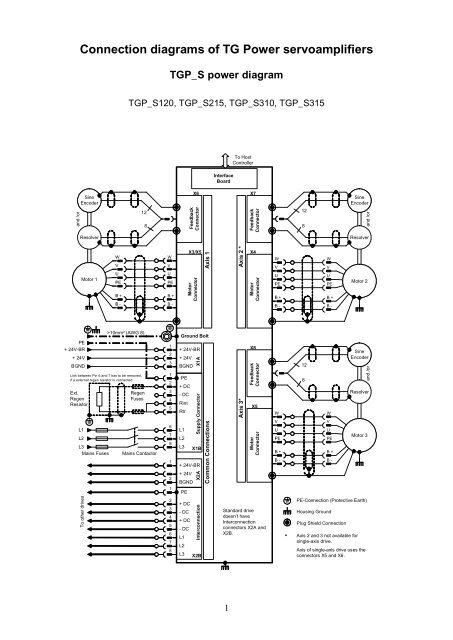
<strong>TG</strong>P_E and <strong>TG</strong>P_A power <strong>diagram</strong><strong>TG</strong>P_E305, <strong>TG</strong>P_A310To HostControllerInterfaceBoardand /orSineEncoder128X6FeddbackConnectorX7FeddbackConnector128SineEncoderand /orResolverResolverMotor 1WVUPEB +B -WVUPEB +B -X3MotorConnectorAxis 1Axis 2X4MotorConnectorWVUPEB +B -WVUPEB +B -Motor 2PEL1L2L3Mains Fusing>10mm² (AWG 8)RegenFusingMains Contactor12312345678Ground Bolt+ 24V-BR+ 24VBGNDPE+ DC-DCRintRtrL1L2X1ASupply ConnectorL3 X1BSupply <strong>Connection</strong>sAxis 3X8FeddbackConnectorX5MotorConnectorWVUPEB +B -128WVUPEB +B -SineEncoderand /orResolverMotor 3PE-<strong>Connection</strong> (Protective Earth)Housing GroundShield <strong>Connection</strong> by Plug2
<strong>TG</strong>P signal <strong>diagram</strong>X11J3J4911 116on offS1StateFaultS1 is the terminationresistor switch on/offbetween CAN_L andCAN_H.11X108J5LED2 (red)Connector X10 Pin Function: digital In/OutputS1 1 Safety function relay SAFE LOCK, free contact (NO)S2 2 Safety function relay SAFE LOCK, free contact (NO)RTO1 3 Ready to operate relay, free contact (NO)RTO2 4 Ready to operate relay, free contact (NO)LOCK 5 Switch on of the driver supply of the power stageENABLE 6 Enables the power stageEN-BRAKE 7 Switch on of the holding brake supply24V-GND 8 Ground for the digital inputs24V 9 24V input for the digital outputsOUT1 10 Digital output 1OUT2 11 Digital output 2IN1 12 Digital Input 1IN2 13 Digital Input 2IN3 14 Digital Input 3IN4 15 Digital Input 4IN5 16 Digital Input 5Connector X11 Pin Function: combined RS232 and CAN-connectionnc 1 Not connectedRxD 2 Receive input for serial interface to the serial port of the PCTxD 3 Transmit output for serial interface to the serial port of the PCnc 4 Not connectedGND_e 5 Interface groundCAN_L 6 CAN connectionL1 7 Linked to pin 8 of X11L2 8 Linked to pin 7 of X11CAN_H 9 CAN connectionConnector J3/J4 Pin Function: CAN-connectionnc 1 Not connectednc 2 Not connectedCAN_L 3 CAN connectionnc 4 Not connectedGND_e 5 Interface groundCAN_H 6 CAN connectionnc 7 Not connectednc 8 Not connectedConnector J5 Pin Function: USB-connectionVCC 1 Voltage supply 5VDCD- 2 Data -D+ 3 Data +GND 4 Ground3
<strong>TG</strong>P signal <strong>diagram</strong> – recommended wiringNoteConnect the followinginputs of X10 terminal toenable the output stage::5 – LOCK – 24V6 – ENABLE – 24V7 – EN-BRAKE – 24V8 – 24V-GND – 0V4
<strong>TG</strong>P signal <strong>diagram</strong> – RS232 and CAN BUS interface wiringRS232 connectionCAN BUS connectionX11 connector (D-SUB9)J3/J4 connector (Rj45)Rj45 connector, female and male5
<strong>TG</strong>P feedback cablesResolver connection cableEnDat connection cable6
Hiperface connection cable<strong>TG</strong>P motor cable7


