ID-H .indd - Mitutoyo Scandinavia AB
ID-H .indd - Mitutoyo Scandinavia AB
ID-H .indd - Mitutoyo Scandinavia AB

You also want an ePaper? Increase the reach of your titles
YUMPU automatically turns print PDFs into web optimized ePapers that Google loves.
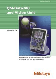
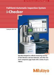
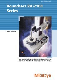
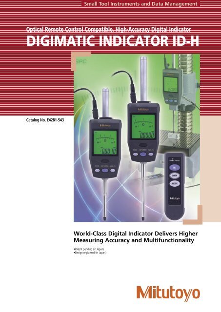
Small Tool Instruments and Data ManagementOptical Remote Control Compatible, High-Accuracy Digital IndicatorDIGIMATIC INDICATOR <strong>ID</strong>-HCatalog No. E4281-543World-Class Digital Indicator Delivers HigherMeasuring Accuracy and Multifunctionality•Patent pending (in Japan)•Design registered (in Japan)
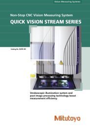
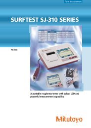
Digimatic Indicator <strong>ID</strong>-HThis new-generation digital indicator offers the excellent accuracy and functionality expected from this class of indicator. Take advantage ofits high accuracy backed up by 0.5µm resolution, remote control functionality via a handheld controller (or an RS-232C interface) and easyrunout measurements with the well-established analog bar display.Accuracy and Resolution Meet the Needs of High Accuracy MeasurementResolution 0.5µmAccuracy 1.5µm (30mm range), 2.5µm (60mm range)Measuring range:30.4 mm543-561Measuring range:60.9 mm543-563Note that the Inspection Certificatesupplied with each instrument,which assures product quality andsafety, cannot be used for obtaininga Calibration Certificate since thepurchase date is not stated.2
AFunctionality Meets the Needs of Diverse Measurement• Tolerance judgmentOK, +NG or -NG is shown for a measurement based on theupper/lower limit values currently set. If an out-of-tolerance value isdetected, the backlight turns red to highlight this fact and help withworkpiece sorting operations.• Analog bar displayThe analog bar display makes it easy to quickly find maximum/minimum readings.Seven ranges from ±0.01mm to ±80mm can be selected to suit thetask in hand.• Measuring maximum value, minimum value andrunoutMaximum value/minimum value measurementMaximum or minimum values are automatically held and displayed.• Large charactersThe 7-digit digital display uses large characters for ease of reading.• Maximum/minimum value based measurementA comparison measurement can be made on the basis of thedetected maximum or minimum values that has been zero-set. Forexample, this method is convenient for measurement in which themaximum value at a workpiece peak is zero-set and other values aremeasured in comparison with this vaue.• Remote operationsThe indicator can be operated remotely by using the remotecontroller, or a personal computer via the built-in RS232C interface.• Two ways of measuringA measurement can be made relative to zero (Incremental) or relativeto an arbitrary value entered into the display (Absolute), whichever ismost convenienent.• Function lockThe setting conditions can be locked to prevent them beingaccidentally changed during use.• Resolution switchingThe resolution can be selected to be 0.0005mm (0.5µm) or 0.001mm(1µm).Difference/Runout measurementDifference (or Total Runout, on a circularworkpiece) between a maximum and aminimum value is held and displayed. Themaximum/minimum values are stored inmemory and can also be displayed.Example: Indicator travel frompoints A to DDifference (or Total Runout) is displayed as A. Dimensions B(maximum value) and C (minimum value) can be recalled frommemory with a simple key sequence.Point B• Direction switchingThe counting direction can be reversed.• Selectable output modeThis indicator not only supports simplerecording of measurement data usingthe well-established Digimatic output,but also enables integration into anintegrated measurement system throughadvanced remote control via the RS-232Cinterface.• Remote spindle liftingThe spindle can be lifted up to 30mmwithout touching the indicator body byusing the dedicated spindle lifting cable(optional accessory). The spindle can belifted over the full stroke by using thelifting knob (optional accessory) thatattaches to the top of the spindle.Lifting knobPoint APoint DBCPoint C3
SpecificationsOrder No. 543-561 543-563Measuring range 30.4mm 60.9mmResolutionSwitchable between 0.0005mmand 0.001mmDisplacement accuracy0.0015mm 0.0025mm(at 20°C)Quantizing error±1 countMeasuring force 2.0N or less 2.5N or lessMeasuring orientation Between vertical (spindle pointing down)and horizontalPositional detection method Photoelectric-type reflection linear encoderMaximum response speed1000mm/sec.Display7-digit LCD, sign, and analog barwith 2-color backlightContact pointSphere R=1.5mm (cemented carbide)Operating temperature range 0°C to 40°CStorage temperature range -10°C to 60°CMain unit mass 290g 305gPower supply 100V, 50/60Hz AC adapter (6V, 1A)Up to 6 digits can be output from the Digimatic port, with truncation from the leading digitif greater than this limit. For example, if the display shows the 7-digit value '123.4565', only'23.4565' would actually be output.543-56390 (60)311.3 (251.3)30 11477.3 (47.3)60.9 (30.4)7.3External Dimensions60ø120ø8-0.009Screw portlonon the contact pointM2.5 (P=0.45)x531 11 Unit: mmThe dimensions in parentheses "( )" are those of 543-561.Standard Accessories• User's Manual• Inspection Certificate• Lifting Lever(Knob)• AC AdapterAccessoriesOptional Accessories1 Remote Controller 21EZA0992 Spindle Lifting Cable 540774(Lifting amount: 30mm)3 Lifting Knob 21EZA1014 Digimatic Connecting Cable (1m) 9369375 Digimatic Connecting Cable (2m) 9650146 RS-232C Connecting Cable (2m) 21EAA1317 Lug-on-Center Back 1010408 Digimatic Mini Processor 264-5049 Digimatic Printer 543-003* <strong>Mitutoyo</strong> will accept a special order for an air lifter upon request.Recommended Stands• Granite Comparator Stand215-154• Comparator Stand215-504• Comparator Stand215-8218641215-50493724
Operations such as zero-setting and presetting can be made without touching the indicator body,thereby avoiding disturbance to the set-up. Also, if multiple indicators are used in an integratedmeasurement system then an arbitrary <strong>ID</strong> number can be set for each one in order to enable remoteoperation of a specific indicator, or remoteoperation of all indicators.• Advantages of remote controlRemote operation without contact with the indicator body ensuresstable measurement. Additionally, the remote controller supportsmeasurement in situations where access to indicators is difficult.If the remote controller <strong>ID</strong> is set to '00',the controller operates all indicators. If thecontroller <strong>ID</strong> is set to the <strong>ID</strong> of one indicatorgroup, the controller operates only thatspecific group of indicators. Up to 14 group <strong>ID</strong>numbers can be set up in the controller.Operation with the Remote Controller (Option)If indicators are used for multipointmeasurement, the remote controller isconvenient for measurements on multipleaxes since the controller can set multipleindicators to zero concurrently.Main functionality• Measurement modeswitching: Switchesbetween the differenttypes of measurement(normal, maximum/minimum, and runout).• Zero-setting: Setsthe display to zeroat any arbitraryposition (Incrementalmeasurement).• Preset value recall:Recalls a preset valueentered into memory(Absolute measurement).• Peak value reset: Resetsthe maximum value,minimum value or runout value alreadystored so the indicator is ready to make thenext measurement.• Data output: Outputs measurement data toan external device.An advanced, remote control system can be built with the built-in RS-232C interface and a PC. A stable,high-accuracy measurement system can be implemented without touching any indicator in the system.(Optional, dedicated cables are required.)· Since the indicator supports RS-232Cinterface commands with key operations,the indicator can be operated from the PCusing these commands. It is also possibleto perform statistical processing andmanagement of measurement data byinstalling a control program in the PC.ReceptacleD-sub 9-pin (female)Inch screw thread specificationBuilding an Advanced Control System via the RS-232C Interface5 4 3 2 19 876• RS-232C Specifications1. Pin assignments in the dedicated cable.Pin Signal Input/ Definition (Purpose)No. name Output1 N.C. – No connection2 TXD OUT Transmit data3 RXD IN Receive data4 DSR IN Data set ready5 GND – Ground6 DTR OUT Data terminal ready7 CTS IN Clear to send8 RTS OUT Request to send9 N.C. – No connection2. Communication protocol (EIA/TIA232compatible)Home position DCE (modem definition),dedicated cable to be used.Communication Half-duplex, TTY protocolmethodBaud rate 4800, 9600bpsBit configuration Start bit: 1Data bit: (7 or 8) ASCII,upper caseParity bit: None, even, oroddStop bit: 2Communication Setting with a parametercondition setting5
Coordinate Measuring MachinesVision Measuring SystemsSurface, Form and ContourMeasurementOptical MeasuringSensor SystemsHardness MeasuringDigital Scale and DRO SystemsSmall Tool Instruments andData Management27.00502 (1) CBS, Printed in JapanNote: All information regarding our products, and in particular the illustrations, drawings, dimensional and performance data containedin this pamphlet, as well as other technical data are to be regarded as approximate average values. We therefore reserve the right tomake changes to the corresponding designs, dimensions and weights. The stated standards, similar technical regulations, descriptions andillustrations of the products were valid at the time of printing. In addition, the latest applicable version of our General Trading Conditionswill apply. Only quotations submitted by ourselves may be regarded as definitive.<strong>Mitutoyo</strong> <strong>Scandinavia</strong> <strong>AB</strong>Släntv. 6 • Box 712SE-194 27 Upplands VäsbyTel: 08-594 109 50Fax: 08-590 924 10info@mitutoyo.sewww.mitutoyo.se