TRC-SFD-1-06 - Tribology Group - Texas A&M University
TRC-SFD-1-06 - Tribology Group - Texas A&M University
TRC-SFD-1-06 - Tribology Group - Texas A&M University

Create successful ePaper yourself
Turn your PDF publications into a flip-book with our unique Google optimized e-Paper software.
List of TablesTable 1 Structural stiffness coefficients and mass of bearing support.............................. 17Table 2 Test conditions for dynamic load tests (CCO). Lubricated <strong>SFD</strong>......................... 28Table 3 <strong>SFD</strong> inertia coefficients identified from circular centered orbit tests (amplitude ofmotion: 50μm, frequency range 20-70 Hz)............................................................... 41Table A1 Measured weight and estimated effective mass of the <strong>SFD</strong> assembly andconnecting rods. ........................................................................................................ 55Table A 2 Structural stiffnesses of support from static load tests..................................... 56Table A 3 Identified parameters from impact tests exerted on <strong>SFD</strong> test section (nolubricant) ................................................................................................................... 57List of FiguresFigure 1 Test rig for dynamic force measurements and flow visualization in a sealed end<strong>SFD</strong> ........................................................................................................................... 12Figure 2 Sealed-end <strong>SFD</strong> assembly cross section view.................................................... 13Figure 3 Sealed-end <strong>SFD</strong> assembly cut view. .................................................................. 14Figure 4 <strong>SFD</strong> housing reference coordinate system and location of sensors. .................. 15Figure 5 Schematic view of lubricant system................................................................... 16Figure 6 Amplitude of displacement response (fundamental frequency component) due toa constant magnitude circular orbit excitation (44 N). (Dry <strong>SFD</strong>, End seal in place)................................................................................................................................... 18Figure 7 Work exerted by input force (= dissipated energy) estimated from combineddamping model (Test 1). (Dry <strong>SFD</strong>, end seal in place) ............................................ 20Figure 8 Equivalent viscous damping (dry friction + residual) versus excitation frequency.(Dry <strong>SFD</strong>, end seal in place)..................................................................................... 21Figure 9 Cut view of <strong>SFD</strong> depicting a flow restrictor ...................................................... 22Figure 10 Lubricant flow rate through <strong>SFD</strong> vs. film land pressure differential (P s -P r ) (2.8mm and 1.1 mm diameter flow restrictors)............................................................... 23Figure 11 Lubricant flow rate versus pressure differential ΔP ra = (P r -P a ) across flowrestrictor. Orifices of diameter 2.8 mm and 1.1 mm................................................. 244
Figure A 3 Impact tests transfer function and analytical fit for motions along Y direction.(Dry system, end seal not in place)........................................................................... 57Figure B 1 Lubricant flow through <strong>SFD</strong> vs. inlet pressure. (average from flowmeasurements for three temperatures 21 C, 27 C, 32 C) .......................................... 63Figure C 1 Excitation load and response orbits (motion and acceleration) fromexperimental data. (20 Hz, Flow restrictor: 2.8 mm, Load: [N], Acceleration [m/s2],displacement [μm]) ................................................................................................... 64Figure C 2 Excitation load and response orbits (motion and acceleration) fromexperimental data. (40 Hz, Flow restrictor: 2.8 mm, Load: [N], Acceleration [m/s2],displacement [μm])).................................................................................................. 65Figure C 3 Excitation load and response orbits (motion and acceleration) fromexperimental data. (70 Hz, Flow restrictor: 2.8 mm, Load: [N], Acceleration [m/s2],displacement [μm])).................................................................................................. 66Figure C 4 Excitation load and response orbits (motion and acceleration) fromexperimental data. (20 Hz, Flow restrictor: 1.1 mm, Load: [N], Acceleration [m/s2],displacement [μm])).................................................................................................. 67Figure C 5 Excitation load and response orbits (motion and acceleration) fromexperimental data. (20 Hz, Flow restrictor: 1.1 mm, Load: [N], Acceleration [m/s2],displacement [μm])).................................................................................................. 68Figure C 6 Excitation load and response orbits (motion and acceleration) fromexperimental data. (70 Hz, Flow restrictor: 1.1 mm, Load: [N], Acceleration [m/s2],displacement [μm])).................................................................................................. 69Figure D 1 Real and imaginary components of complex dynamic stiffness (F x /x).( Flowrestrictor: 2.8 mm. Dry Friction force: 34 N) ........................................................... 71Figure D 2 Real and imaginary components of complex dynamic stiffness (F y /y).( Flowrestrictor: 2.8 mm. Dry Friction force: 34 N) ........................................................... 72Figure D 3 Real and imaginary components of complex dynamic stiffness (F x /x).( Flowrestrictor: 1.1 mm. Dry Friction force: 34 N) ........................................................... 73Figure D 4 Real and imaginary components of complex dynamic stiffness (F y /y).( Flowrestrictor: 1.1 mm. Dry Friction force: 34 N) ........................................................... 747
Nomenclaturec Bearing radial clearance [m]C d Empirical orifice discharge coefficient [-]C rv Structure remnant damping coefficient [N.s/m]C seal Equivalent viscous damping for mechanical seal [N.s/m]C s-αβ Identified system damping coefficients [N.s/m] α,β=x,yC <strong>SFD</strong>αβ Identified squeeze film damping coefficients [N.s/m] α,β=x,yd Orice diameter in flow restrictor [m]D 2 R. Damper journal diameter [m]e Amplitude or radius of circular centered orbit [m]E dry Energy dissipated by dry-friction force [J]E rv Energy dissipated by structure[J]E v Energy dissipated by viscous forces [J]F x,y External (shaker) forces applied to bearing [N]F , Frequency components of external forces applied to bearing [N]xF yF μ Dry friction force from contact in mechanical seal [N]f n Test system natural frequency [Hz]H αβ Dynamic impedances [N/m], α,β=x,yK sx ,K sy Structural (support) stiffnesses [N/m]L, R Length and radius of <strong>SFD</strong> land [m]M Mass of bearing housing [kg]M f Estimated mass of lubricant (feed plenum & end groove) [kg]M <strong>SFD</strong>αβ Squeeze film inertia coefficients [kg], α,β=x,yM s-αβ Identified system inertia coefficients [kg], α,β=x,yP a Ambient pressure [bar]P s , P r Inlet (supply) pressure and pressure at recirculation annulus [bar]Q Lubricant flow rate [LPM]T Lubricant temperature [°C]V Velocity vector of bearing motions [m/s]W Work from external forces [J]x,y Bearing dynamic motions along X,Y directions [m]x,y Complex components of bearing motions [m]Z (ω) Vector of displacements in frequency domain [m]ΔP <strong>SFD</strong>max Max (P s -P r ) [bar]ΔP <strong>SFD</strong> P s -P r . Pressure difference across film land[bar]ΔP ra P s -P a . Pressure difference across discharge flow restrictor [bar]φ Phase lag of damper motion relative to excitation forceμ Dry friction coefficient from contact sealρ, η Lubricant density [kg/m 3 ] and viscosity [Pa-s]ω Excitation frequency [rad/s]ζ C/[2 (K s M) 1/2 ]. Viscous damping ratio8
I IntroductionSqueeze film Dampers (<strong>SFD</strong>s) aid to reduce rotor vibrations and to increase stabilitymargins in high performance rotating machinery. The forced performance (dampingcapability) of a <strong>SFD</strong> depends on its geometrical configuration and its operationalparameters such as flow regime, type of journal motion, lubricant viscosity cavitationtype, and air entrapment among others [1]. For numerous years, research efforts havebeen conducted to elucidate the parameters and configurations that maximize <strong>SFD</strong>performance for different applications.Presently, with increasing rotor flexibilities and shaft speeds, high performanceturbomachinery undergoes high dynamic loads and large displacements. Under theseconditions, air ingestion and entrapment compromise the performance of <strong>SFD</strong>s with openends or partially sealed configurations. Seal <strong>SFD</strong>s are essential for providing adequatedamping under such demanding conditions, as they are less prone to airingestion/entrapment than open end dampers when operating at high frequencies.Different types of seals have been adopted (O-rings, end plates, etc.), yet there are manymore seals and other <strong>SFD</strong> geometric configurations (i.e. oil feeding arrangement,grooves) used in practice and not yet thoroughly investigated. A prior <strong>TRC</strong> technicalreport [2] presents a parameter identification for a contained <strong>SFD</strong> with a mechanical sealthat effectively eliminates lubricant side leakage. This damper type, when not in use,must contain the lubricant in the film lands for extended periods of time. The test systemforce coefficients are identified from unidirectional dynamic loads. The test procedurefirst determines the system structural parameters as well as the equivalent viscous actionof the dry-friction force at the mechanical seal interface. Next, squeeze film damping andinertia force coefficients are extracted from the test system force coefficients withlubricant flowing through the damper. This report furthers the experimental workadvanced in [2], to asses the forced performance of the test damper under circular orbitmotions.9
II Literature ReviewDella Pietra and Adilleta [3, 4] summarize most of the experimental and analyticalworks conducted on <strong>SFD</strong>s during the past 40 years. Reference [3] details the rudiments of<strong>SFD</strong> operation, the theoretical models advanced and the experimental research conductedon controlled motion test rigs. The topics reviewed include fluid inertia, groove geometry,end sealing, and lubricant cavitation and their effect on the forced performance of <strong>SFD</strong>s.Reference [4] addresses to rotordynamic analyses and field evaluation of <strong>SFD</strong>s installedin actual rotating equipment. The review closes with descriptions of unconventional andnovel <strong>SFD</strong> designs.References [5-10] report <strong>SFD</strong> parameter identification on controlled motion test rigsusing time and frequency domain approaches. In general, where damping and inertiaforce coefficients have been experimentally determined, classical lubrication modelsrender reliable predictions only for damping coefficients [11]. To date, the main issues ofcontinued scrutiny include the proper prediction of fluid inertia coefficients, the adequatemodeling of circumferential grooves and end seals, and the understanding of gasingestion and entrapment.Common end seals in <strong>SFD</strong>s include O-rings, piston rings, and end plates (clearancegap). The design of end seals is highly empirical and requires of “leakage correctionfactors” that can only be extracted from careful experimentation [12]. Levesley andHolmes [13] find experimentally that piston-ring end seals lead to larger dampingcoefficients than when using end plate seals, for example. On the other hand, fromrotordynamic tests, De Santiago and San Andrés [14] show that integral dampers sealedwith simple end plates are effective in increasing the overall damping while reducing thelubricant trough flow. The experiments show that rotor synchronous response amplitudeswhile crossing two critical speeds are proportional to the mass imbalance displacement,thus evidencing the linearity of the integral <strong>SFD</strong> elements. In [14], predictions ofdamping coefficients are in good agreement with the test data.More recently, Kim and Lee [15] present both an analysis and tests of a sealed <strong>SFD</strong>with a central feeding groove. Two types of seals are modeled, a single-stage and twostageliquid seals. Predictions including the two-stage seal agree with the test <strong>SFD</strong> inertiaforce coefficients, but underestimate the damping force coefficients.10
For the past 20 years, the authors’ research group has contributed to the extensiveexperimental and analytical body of work conducted on <strong>SFD</strong>s, including efforts toelucidate the issue of gas entrainment and entrapment; and advancing simple engineeringmodels for reliable prediction of open-ends <strong>SFD</strong> forced performance, see [16, 17] forexample. The research also focuses on the development of accurate parameteridentification techniques with analysis of test data in the frequency domain [18]. In spiteof the progress advanced, there are still issues to be fully understood. One is the poorcorrelation between predicted and experimentally derived added mass coefficients; withtheory typically under predicting by ~50% the measurements. Another issue relates toend sealing, with some actual <strong>SFD</strong> configurations showing extreme complexity and fewexperimental results to verify their predicted performance. Thus, more analytical andexperimental works are needed to fully understand and maximize the performance of<strong>SFD</strong>s.This report extends prior art given in [2] by presenting dynamic load experimentsgenerating circular centered orbits (CCO); a motion condition more realistic to thedynamics of rotating machinery. The aims are to extend the identification method tocircular motions, to obtain the force coefficients of the <strong>SFD</strong>-seal system and <strong>SFD</strong> alone,and to assess any differences with earlier test results derived from unidirectional motions.Detailed descriptions of the test <strong>SFD</strong> rig, parameter identification procedure andexperimental results follow.11
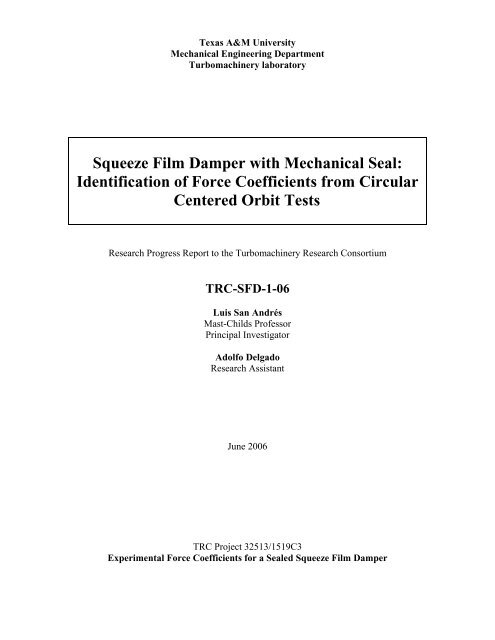
III Test Rig DescriptionThe test rig comprises of the same structure reported in a prior <strong>TRC</strong> research report[2]. Figure 1 depicts a schematic view of the test rig consisting of a bearing assembly anda vertical rigid shaft holding a steel journal, 127 mm (5”) in diameter and 76.2 mm (3”)in length. The shaft is supported on three precision ball bearings. The natural frequencyof the shaft and journal equals 400 Hz [18]. The bearing assembly, shown in Figure 4,consists of an acrylic bearing sandwiched by two thick steel plates and connected withvertical steel plates. The composite bearing housing hangs from a top structure with foursteel rods giving a structural stiffness to the test bearing section. On the top structure, amechanism comprising of two flat plates - one able to slide- allows centering and offcenteringpositioning of the bearing with respect to its journal. The damper film landlength (L) is 25.4 mm and the film radial clearance (c) is 127 μm ± 6 μm at roomtemperature (23 0 C).Top SupportPlateMain FramesupportsSteelRodsBottom SupportPlateAccelerometerOscilloscopeXAcrylicHousingShakerSignalDischargeorificeRing carrierJournalVerticalplateLoad CellPowerSupplyPC DAQShaft1)127mm (5 in)ShakerSignal inputShaker Cooler FanTo ComputerFigure 1 Test rig for dynamic force measurements and flow visualization in a sealed end<strong>SFD</strong>12
Figures 2 and Figure 3 depict a cross section and a cut view of the end sealed <strong>SFD</strong>design along with its components, respectively. The bearing housing design integrates a<strong>SFD</strong> land and an annulus that accommodates a metallic ring (ring holder). This metallicring along with the journal bottom surface provides a metal-metal mechanical seal. Awave spring, pushing the ring holder against the journal, applies a contact force betweenthe matting surfaces. The bearing housing also incorporates a discharge recirculationannulus at one end of the squeeze film land, 4.25 mm deep and 7.62 mm in length. Theoil is fed from the top and exits the damper at the recirculation annulus through fouroutlet ports. The discharge flow area is regulated by flow restrictors. The current testsinclude two sets of flow restrictors; one with 2.8 mm diameter holes, and other with 1.1mm diameter holes.Oil inletEddycurrentsensorPlexiglasBearingVerticalplateRecirculationannulusHousingTop plateO-ringsO-ringsWave springRing carrierJournalFlow Piperestrictor insertDischargeorificeShaftBottom plateFigure 2 Sealed-end <strong>SFD</strong> assembly cross section view.13
Oil inletEddy current sensorHousingtop plateNominal clearance0.005 in (0.127 mm)Plexiglas bearingJournalVerticalplateShaftRing carrierWavespringRecirculation annulusBottom plate2 in (50.8 mm)Figure 3 Sealed-end <strong>SFD</strong> assembly cut view.Figure 4 shows the sensor disposition and reference coordinate system on the <strong>SFD</strong>housing. Two electromagnetic shakers (max. 100 lbf or 448 N), suspended from separatesteel frames, stand to provide excitation forces onto the test device. Slender steel stingersconnect the shaker to the bearing housing (x and y directions). Piezoelectric load cells arefastened to the side plates and the one of the stingers end. The top disk allocates twoaccelerometers (x,y), right above the side plates.14
1:Accelerometers2: Load Cells3: Stingers4: Eddy currentsensor holder411XY23Figure 4 <strong>SFD</strong> housing reference coordinate system and location of sensors.III.1 Data acquisition and post-processingA DAQ board serves as an interface to connect the instrumentation, includingpressure sensors, accelerometers, load cells and eddy current sensors to a PC. The data isrecorded using a modified version of a Labview® virtual instrument (VI) initiallydesigned by Diaz [19]. The modified version adds the following features:* Control oil pump flow rate through motor frequency controller (using a relay box).* Control magnitude and frequency of two shakers (real time-no need to stop operation)* Control system to automatically adjust shaker input level to match a given load ordisplacement magnitude (selected by the user).* Automated operation for multi-frequency tests.A Mathcad® worksheet processes the recorded time traces (displacements,acceleration, forces), transform the data into the frequency domain, and perform thespectral analysis to obtain the test <strong>SFD</strong> force coefficients.15
III.2 Lubrication systemFigure 5 depicts the lubrication system of the test rig, presently including twoflowmeters and pipe lines for the four outlets of the new <strong>SFD</strong> configuration (end sealed).The flowmeters, located at the <strong>SFD</strong> inlet and outlet lubrication lines, allow estimation ofleakage flow through the <strong>SFD</strong> end seal.ReservoirOil heaterT1Main PumpPressure tapThermocoupleFlowmeterF2Wye -adaptersT3Return PumpT2<strong>SFD</strong>Oil tray(oil leakage)F1PressureTransducersFigure 5 Schematic view of lubricant system.The piping for connecting the <strong>SFD</strong> multiple oil outlets is symmetric in order toequalize the friction losses for each of the four outlets. This implies same longitude hosesand symmetric wye adapters.The ISO VG 2 lubricant, specific gravity equal to 0.80, and its absolute viscositydepends on temperature (°C) as−0.01665 ( T −23.6)η(T ) = 2.8ecPoise (1)The relationship was obtained from viscosity measurements using a rheologicalviscometer [20].16
t + T1EdryFμ| V | dtt1= ∫ (3)where V is the velocity vector (V x ,V y ) constructed from the displacement Fouriercoefficients (no velocity data is directly available). On the other hand, some energy isalso dissipated by (residual) viscous effectst + T2 2( )∫ (4)1Erv = Crv Vtx+ Vydt1where C rv is a residual viscous damping coefficient. The overall damping parameters areobtained assuming a combination of dry friction damping (arising from the endmechanical seal) and a residual viscous damping representing the small dampingcontribution from other sources (i.e. steel rods). The identification relies on equating E dry+ E rv =Work .The friction force relates to the magnitude of the contact force at the mechanical sealinterface. Thus, the friction force can be modified by changing the compression of thewave spring that pushes ring holder against the journal bottom surface. The currentcontact force (i.e. normal force) at the seal interface is estimated at 90 N (± 10 N) usingthe friction coefficient of the seal mating surfaces (μ ~0.37) identified in [2].The magnitude of the residual viscous damping coefficient (C rv = 60 Ns/m) is similar(within ~10 %) to the one obtained from impact tests on the dry system without the sealin place). This coefficient represents the viscous damping introduced by the support rods.Figure 7 shows the work exerted by the input force and the estimated energydissipated by the combined damping model for each test. The dissipated energy estimatedwith a friction force of 34 N and the remnant viscous damping 60 Ns/m, is in goodagreement with the actual work input to the system.19
0.02Work-Energy Dissipated [N.m]0.0150.010.005020 22 24 26 28 30 32 34 36 38 40 42Frequency [Hz]Work (input force)Energy dissipated (c=60 (C rv =60 N.s/m, Ff=34 F μ N)Figure 7 Work exerted by input force (= dissipated energy) estimated from combineddamping model (Test 1). (Dry <strong>SFD</strong>, end seal in place)Figure 8 depicts the ratio Im(F/X), which is proportional to the equivalent viscousdamping coefficient for the dry system, i.e. Cω. Notice that the viscous dampingcontribution, C rv = 60 N.s/m, is rather small compared to the total viscous damping of thesystem. This indicates that the damping arising from the seal dry friction interaction (F μ =34 N) accounts for most of the system energy dissipation.20
12Im(F/X)/w [kN/m]963010 20 30 40 50Frequency [Hz]Test Data (system damping)Identified dry friction damping contribution (F(Fdry μ = 34 = N) 34 N)Viscous damping contributionFigure 8 Equivalent viscous damping (dry friction + residual) versus excitation frequency.(Dry <strong>SFD</strong>, end seal in place)21
V Measurements of flow rate in lubricated <strong>SFD</strong>This section includes flow measurements using 1.1 mm diameter flow restrictors.Prior measurements in [2] were conducted with 2.8 mm diameter flow restrictors. Eachflow restrictor consists of a pipe insert with a thru hole that restricts the outlet flow fromthe recirculation annulus. Figure 9 depicts a cross sectional area of the test system andfeaturing details of the flow restrictor.FlowinFlow Restrictorout FlowoutFlowrestrictor(4),hole dia. 0.28 cmHole, diameter dSide leakage(through sealedinterfaces)Wave springRecirculation annulusMechanical sealFigure 9 Cut view of <strong>SFD</strong> depicting a flow restrictorThe seal performance is determined by verifying that the mechanical seal assemblyprevents side leakage of lubricant, and thus the recirculation annulus is completely filledwith oil at all times. During the flow measurements, the seal effectively prevented anyside leakage, thus indicating the contact force is sufficiently large to seal the interfacebetween the damper journal and contact ring.Figure 10 depicts the lubricant flow rate versus pressure drop across squeeze filmland (ΔP <strong>SFD</strong> = P s -P r ) for flow restrictors with holes of diameter 2.8 mm [2] and 1.1 mm.The graphs include results for three oil inlet temperatures (21-32 o C). Filled symbolsrepresent the results for the restrictor with a hole of 2.8 mm. The measurements show that,as the oil temperature increases (viscosity decreases), the flow rate increases relative tothe pressure differential across the damper film land. As expected, the lubricant flow22
ates are similar for identical pressure differentials. Note that smaller size holes restrictthe flow and increase the pressure in the recirculation annulus; thus then the smaller flowrates and pressure differentials recorded for 1.1 mm holes.43.53Flow Rate (LPM)2.521.510.5Flow restrictor(Diameter)Oil temperature2.8 mm1.1 mm21 21 C27 27 C32 32 C21 21 C27 27 C32 32 C00 0.1 0.2 0.3 0.4 0.5 0.6 0.7 0.8 0.9ΔP (bar)Figure 10 Lubricant flow rate through <strong>SFD</strong> vs. film land pressure differential (P s -P r ) (2.8mm and 1.1 mm diameter flow restrictors)Figure 11 presents the lubricant flow rate versus pressure drop across the flowrestrictors, ΔP ra = P r -P a , when using 2.8 mm and 1.1 mm hole diameters. The pressurebuild up in the recirculation annulus with the small 1.1 mm diameter holes is about sixtimes larger than for the larger orifices (2.8 mm); and consequently the lubricant flowrate is much lower (~ 50%) . Note that the relationship between flow rate and pressuredifferential is non linear.23
1.210.8Flow Rate0.60.40.2Flow restrictor(Diameter)Oil temperature21 C2.827 mm C21 C27 32 C32 C1.1 mm21 C27 C32 C00.00 0.20 0.40 0.60 0.80 1.00 1.20ΔP/ΔPmaxFigure 13 Ratio of test flow rate to predicted flow rate versus film land pressure differenceratio (2.8 mm and 1.1 mm diameter flow restrictors)For later modeling of the sealed <strong>SFD</strong>, it is necessary to establish a relationshipbetween the flow rate, the orifice diameter (d) and pressure drop ΔP ra =P r –P a [23]Q = 4Cd( P − P )2π d 2r4 ρa(6)where C d is an empirical orifice coefficient. Figure 14 shows the ratio of the measuredflow to the predictions derived from Eq. (6) versus the pressure differential ratio(ΔP ra /max(ΔP ra )) for the 1.1 mm diameter restrictor. The results show a ratio nearly equalto one, thus demonstrating Eq. (6) models best the flow through the orifice. For thepredictions, an orifice discharge coefficient C d =1 was used.For the largest orifice (2.8 mm), the pressure at the recirculation annulus is nearlyambient pressure, thus the flow rate is largest and not regulated by the orifice restrictor.Further analysis will be conducted later to find the equivalent flow resistance of thetest system, i.e. squeeze film land and orifices in series, to determine an “end seal” likecoefficient for usage in predictions of <strong>SFD</strong> forced performance.26
VI Identification of Squeeze Film Damping and InertiaCoefficients for Lubricated <strong>SFD</strong>VI.1 Experimental procedureWith lubricant flowing through the damper lands, single frequency dynamic loadsare applied into the test system to produce centered circular orbits (CCO). The testsinclude four increasing motion amplitudes (12 μm to 50 μm) at frequencies rangingfrom 20 Hz to 70 Hz. and for two sets of flow restrictors (2.8 mm and 1.1mmdiameter holes). The largest motion amplitude amounts to ~ 40% of the damper radialclearance. Table 1 presents the test conditions.Table 2 Test conditions for dynamic load tests (CCO). Lubricated <strong>SFD</strong>Inlet Pressure (P s ) *31 kPaRecirculation Annulus Pressure (P r )* 8.6 kPa-15.5 kPaFrequency Range20-70 Hz (2 Hz step)Lubricant temperature (T) 23-25 0 C (73-77 0 F)Viscosity (η)3.1 cP- 2.8 cPClearance (c)125-127 μm (4.9-5 mils)Orbit amplitude (e)12-50 μm (0.5-2 mils)Flow restrictors (hole diameter) 2.8 mm and 1.1mm*: Gauge pressure.Throughout the test frequency range, the applied dynamic load is set to maintainconstant amplitude circular orbits (12 μm, 25 μm, 38 μm, 50 μm). Figures 15 through 18show the applied loads (Y vs. X) and ensuing displacement orbits at 20 Hz and 70 Hz forthe two flow restrictor configurations tested. Appendix C includes excitation force anddisplacements orbits at other selected frequencies ranging from 20 Hz to 70 Hz.28
300150Y Load [N]-300 -150 0 150300-150-300X Load [N]20 Hz130Y Displacement [μm]12 μm25 μm38 μm65-130 -65 0 6550 μm-65Max. clearance:127 μm20 Hz130-130X Displacement [μm]Figure 15 Recorded load and ensuing displacement orbits for four amplitude load levels.Clearance circle noted . (20 Hz, lubricated <strong>SFD</strong>, CCO, 2.8 mm diameter flow restrictor)29
300150Y Load [N]-300 -150 0 150300-150-300X Load [N]70 Hz130Y Displacement [μm]12 μm25 μm38 μm65-130 -65 0 6550 μm65Max. clearance:127 μm70 Hz130-130X Displacement [μm]Figure 16 Recorded load and ensuing displacement orbits for four amplitude load levels.Clearance circle noted. (70 Hz, lubricated <strong>SFD</strong>, CCO, 2.8 mm diameter flow restrictor)30
300150Y Load [N]-300 -150 0 150300-15020 Hz-300X Load [N]130Y Displacement [μm]12 μm25 μm38 μm65-130 -65 0 6550 μm-65Max. clearance:127 μm20 Hz130-130X Displacement [μm]Figure 17 Recorded load and ensuing displacement orbits for four amplitude load levels.Clearance circle noted. (20 Hz, lubricated <strong>SFD</strong>, CCO, 1.1 mm diameter flow restrictor)31
300150Y Load [N]-300 -150 0 150300-150-300X Load [N]70 Hz130Y Displacement [μm]12 μm25 μm38 μm65-130 -65 0 6550 μm-65Max. clearance:127 μm70 Hz130-130X Displacement [μm]Figure 18 Recorded loads and ensuing displacement orbits for four amplitude load levels.Clearance circle noted. (70 Hz, lubricated <strong>SFD</strong>, CCO, 1.1 mm diameter flow restrictor)Figures 19 and 20 show the amplitude of the dynamic load versus frequency whenusing 2.8 mm and 1.1 mm diameter flow restrictors, respectively. The dynamic loadincreases steadily with frequency in order to maintain the design (preset) constant orbitamplitude. The amplitudes of bearing orbital motion are labeled on each graph.32
300250XY200Load [N]150Amplitude of motion100D:50 μmD:38 μmD:25 μmD:12 μm5000 10 20 30 40 50 60 70 80Frequency [Hz]Figure 19 Amplitudes of dynamic load versus excitation frequency (4 tests- CCO,lubricated <strong>SFD</strong>, 2.8 mm diameter flow restrictor)300250XY200Load [N]150Amplitude of motion10050D:50 μmD:38 μmD:25 μmD:12 μm00 10 20 30 40 50 60 70 80Frequency [Hz]Figure 20 Amplitudes of dynamic load versus excitation frequency (4 tests- CCO,lubricated <strong>SFD</strong>,1.1 mm diameter flow restrictor)33
Figures 21 and 22 depict the hydrodynamic pressure waves at the <strong>SFD</strong> land andrecirculation annulus when exiting the system at 70 Hz, for the two sets of flowrestrictors used. In the case of the configuration with the larger flow area (2.8 mm holes)the dynamic pressure in the <strong>SFD</strong> land reaches lower values than that recorded when usingthe smaller flow restrictor configuration. For both flow restrictor configurations, there areno signs of oil cavitation or air entrapment, thus evidencing the effectiveness of themechanical seal. Regarding the pressure at the recirculation annulus, the configurationwith 2.8 mm diameter holes shows larger dynamic pressures than those obtained whenusing 1.1 mm diameter flow restrictors; however the static (mean) pressure is lower. Thisdifference is attributed to a variation of the sensor gain as explained below.Absolute Pressure Pressure [bar] [bar]Absolute Pressure [bar]21.751.51.2510.750.50.25Pressure @ <strong>SFD</strong> LandFilm thickness0.25(3x) 0[mm]-0.25Pressure @ Recirculation annulus00 5 10 15 20time*w [rad]Time*ω [rad]Figure 21 Dynamic pressure measurements at <strong>SFD</strong> land and recirculation annulus(including film thickness at sensor location). (70 Hz, 50 μm orbit amplitude, 2.8 mm flowrestrictor, supply Pressure= 31 kPa)-Film thickness amplified (3x) to enhance view.34
21.75Film thickness(3x)0.250[mm]Absolute Pressure [bar]Absolute Pressure [bar] [bar]1.51.2510.750.50.25Pressure @ <strong>SFD</strong> LandPressure @ Recirculation annulus−0.2500 5 10 15 20time*w [rad]Time*ω [rad]Figure 22 Dynamic ressure measurements at <strong>SFD</strong> land and recirculation annulus(including film thickess at sensor location). (70 Hz, 50 μm orbit amplitude, 1.1 mm flowrestrictor, supply Pressure= 31 kPa)-Film thickness amplified (3x) to enhance view.Figure 23 shows the peak to peak values of the dynamic pressure waves recorded atthe <strong>SFD</strong> land and recirculation annulus for each set of flow restrictors (2.8 mm and 1.1mm diameter flow restrictors) for 50 μm orbit amplitudes. Figure 24 presents similarresults recorded for 12 μm orbit amplitudes. Note the difference of scales betweenFigures 23 and 24. For both sets of flow restrictors the peak pressures show the sametrend. The dynamic pressures in the <strong>SFD</strong> land for the largest amplitude (50 μm) areconsiderably larger than those recorded for the small orbit of 12 μm. Furthermore, thepressure at the <strong>SFD</strong> land for the 12 μm amplitude orbits is similar to the pressurerecorded at the recirculation annulus for the same orbit amplitude.On the other hand, the pressure at the recirculation annulus for both sets of flowrestrictors is nearly independent of the frequency and similar for both sets up to 40 Hz.From 40 Hz the recirculation annulus pressure fluctuation for the larger flow restrictorincreases and deviates from the value for the smaller flow restrictor. The rationale for thesudden increase is most likely due to a change in the flow field within the recirculationannulus.Note that for the 2.8 mm diameter flow restrictors and at the highest test frequencies,the gradient of the pressure in the <strong>SFD</strong> land is slightly larger than that recorded when35
using 1.1 mm flow restrictors. This indicates that the latter configuration is slightly lessprone to oil cavitation than the other configuration (2.8 mm).1.2Pk-Pk Pressure (bar)0.90.60.3Pressure @<strong>SFD</strong> landPressure @recirculation annulusFlow restrictor diameter2.8 mm1.1 mm00 20 40 60 80Frequency (Hz)Figure 23 Pk-pk dynamic pressures in <strong>SFD</strong> land and recirculation annulus. (50 μm orbitamplitude, 2.8 mm and 1.1 mm diameter flow restrictor)0.3Flow restrictor diameter2.8 mm1.1 mmPk-Pk Pressure (bar)0.20.1Pressure @<strong>SFD</strong> landPressure @recirculation annulus00 20 40 60 80Frequency (Hz)Figure 24 Pk-pk dynamic pressures in <strong>SFD</strong> land and recirculation annulus. (12 μm orbitamplitude, 2.8 mm and 1.1 mm diameter flow restrictor)36
VI.2 Parameter identification methodThis section describes the identification method employed to estimate the <strong>SFD</strong>parameters from centered circular orbit tests. The equations of motion for the test bearingsection are⎡M + Mf0 ⎤⎧&&x⎫⎡Ksx 0 ⎤⎧x⎫⎧Fx⎫ ⎧Fx⎫ ⎧Fx⎫⎢0 M M⎥⎨ ⎬+ ⎢f y 0 K⎥⎨ ⎬= ⎨ ⎬ −⎨ ⎬ −⎨ ⎬⎣ + ⎦⎩&&⎭ ⎣ sy⎦⎩y⎭⎩Fy⎭ ⎩Fy⎭ ⎩Fy⎭seal<strong>SFD</strong>(7)where M f =0.62 kg represents the estimated mass of fluid enclosed in the plenum abovethe fluid film land section and in the recirculation annulus. The <strong>SFD</strong> reaction forcesfollow the linearized description:⎧Fx⎫⎨ ⎬⎩Fy⎭<strong>SFD</strong>⎡C= ⎢⎣C<strong>SFD</strong> xx<strong>SFD</strong> yxCC<strong>SFD</strong> xy<strong>SFD</strong> yy⎤⎥⎦⎧x&⎫⎨ ⎬⎩y&⎭⎡M+ ⎢⎣M<strong>SFD</strong> xx<strong>SFD</strong> yxMM<strong>SFD</strong> xy<strong>SFD</strong> yy⎤ ⎧&&x⎫⎥ ⎨ ⎬⎦ ⎩&&y⎭(8)where { C<strong>SFD</strong>}αβ αβ=x,y , { M<strong>SFD</strong>}αβ αβ=x,y are the squeeze film damping and inertia forcecoefficients, respectively. The mechanical seal reaction force is expressed as⎧ x&⎫⎧Fx⎫ ⎪V⎪ ⎪⎧Csealx&x ⎪⎫⎨ ⎬ = Fμ⎨ ⎬ ≈ ⎨ ⎬⎩Fy⎭ y Cseal ⎪&⎪ ⎪ sealy&⎩ y ⎪⎭⎪⎩V⎪⎭(9)where V=( x& , y& ) T is the velocity vector and F μ is the dry-friction force and. C seal is anequivalent viscous damping coefficient that follows from equating the energy dissipatedby viscous forces to the energy dissipated from dry friction forces over one period ofmotion [20],C2∫ V dt = Edry= F ∫ V μsign(V dtF→μC seal= ;α=x,y(10)ω xseal)In the frequency domain the system can be represented asα37
⎡⎣M i C K ⎤⎦Z H( )ZωFω( ω)(11)2− ω + ω +( ω) =( )=where⎡Ms−xxM ⎤ ⎡Ks−xys0 ⎤x⎡Cs−xxCs−xy⎤M = ⎢⎥ , K = ⎢ ⎥, C =;⎣Ms−yxMs−yy ⎦ ⎢ 0 K⎢ ⎥⎣sy⎥⎦⎣Cs−yxCs−yy ⎦withCCs−xxs−yx= C= C<strong>SFD</strong><strong>SFD</strong>xxyx+ C; Cseals−xy+ C= Crv<strong>SFD</strong>; Cxys−yy= C<strong>SFD</strong>yy+ Cseal+ Crv;(12)MMs−xxs−yx= M= M<strong>SFD</strong><strong>SFD</strong>xxyx+ M; Mfs−xy+ M ; M= M<strong>SFD</strong>s−yyxy= M<strong>SFD</strong>yy+ Mf+ M ;and Z( ω ), F( ω )are the discrete Fourier Transform (DFT) of time varying displacementsand forces, respectively. In particular, a periodic forcing function can be represented as( )ωF () t = F cos( ωt) + F sin( ωt)= F − iF e = F ei t iωtx xc xs xc xs x( )ωF () t = F cos( ωt) + F sin( ωt)= F − iF e = F ei t iωty yc ys yc ys y(13)Subsequently, the bearing displacement and accelerations are also periodic withidentical frequency (ω), and expressed as⎧x⎫ ⎧x−ix⎫ ⎧x⎫ ⎧&&x⎫⎧a⎫Z e e e⎩ ⎭ ⎩ ⎭ ⎩ ⎭ ⎩ ⎭ ⎩ ⎭c s iωt iωt x iωt( ω) = ⎨ ⎬= ⎨ ⎬ = ⎨ ⎬ ; ⎨ ⎬=⎨ ⎬y yac−i ysy && y y(14)For circular motions, the displacements along x and y are of identical magnitude but180 0 out of phase, y = − i x . Then, Eq. (7) becomes22( K − ω M + ωC) + i( ωC+ ω M )sxs−xxs−xys−xxs−xy⎛ Fx=⎜⎝ x( ) ( )⎟ ⎞⎜ ⎛ F22yKs− ω Ms−yy+ ωCs−yx+ i ωCs−yy+ ω Ms−yx=y⎝ y ⎠⎞⎟⎠(15)38
where M s-xx , C s-xx , M s-yy and C s-yy represent the test system inertia and damping forcecoefficients, see elements in matrices of Eq. (12). The system mass coefficients can bereadily identified from Eq. (15). The real part of the complex dynamic stiffness⎛ F ⎞ ⎛ F ⎞x y( ⎜ ⎟, ⎜ ⎟) is curve fitted to a second order polynomial (with C s-xy =C s-xy =0),⎝ x ⎠ ⎝ y ⎠rendering correlation values of 97 %. The inertia of the squeeze film is extracted from theexpression:MM<strong>SFD</strong>xx<strong>SFD</strong>yy= M= Ms − xxs−yy− M − M− M − MffThe system damping coefficients are obtained from the imaginary part of the dynamicstiffnesses in Eq. (15), i.e.(16)Cs−xx⎛ F ⎞xIm⎜⎟⎝ x ⎠ω= , Cs−yy=⎛ FyIm⎜⎝yω⎞⎟⎠(17)where M s-xy =M s-yx =0 since the squeeze film does not show any lubricant cavitation.Squeeze film coefficients at each excitation frequency follow fromC<strong>SFD</strong>xx = Cs−xx −Cseal −CrvC = C −C − C(18)<strong>SFD</strong>yy s−yy seal rvwhere C rv = 60 N.s/m and C seal is given in Figure 7(F μ = 34 N). This approach rendersdamping coefficients that vary with test frequency. A more suitable method, reducingFμuncertainty in the identification, substitutes ω Cseal= into Eq. (17) to renderxωωC<strong>SFD</strong>xxC<strong>SFD</strong>yy⎛ F Fx⎞= Im⎜⎟ −⎝ x ⎠ x⎛ Fy⎞ F= Im⎜⎟−y⎝ ⎠ yμ −μ −ω Crvω Crv(19)A first order curve fit of Eq. (19) over the test frequency range renders the squeezefilm damping coefficients C <strong>SFD</strong>xx and C <strong>SFD</strong>yy . Note that these coefficients represent39
“average” values over a frequency range. Appendix D presents the imaginary part of thedynamic impedances and the right hand side of Eq. (19) for all the load amplitudes tested.The data shown evidences the differences from both procedures, i.e. frequency averagefrom linear curve fit and local slope of imaginary part of transfer function.For comparison to the identified parameters, the direct damping coefficient for a shortlength open ends <strong>SFD</strong> describing circular centered orbits is [1]( C<strong>SFD</strong>xxC<strong>SFD</strong>yy)πηR⎛ L ⎞⎛c1 e ⎞ ⎝ ⎠⎜ − ⎡ ⎤⎣ c ⎦ ⎟⎝ ⎠= =theory23/2 ⎜ ⎟3This formula applies to a full film. Above e is the orbit radius and η is the lubricantviscosity. At the temperature tested, the measured clearance (c) equals 0.125 mm. Thepredicted fluid inertia coefficient, Eq. (21) below, uses twice the physical length of thedamper land when properly accounting for the outlet boundary condition in the test <strong>SFD</strong>element, [24]ρ π R( )( 2 L)M = M =<strong>SFD</strong>xx<strong>SFD</strong>yytheory2×10c3(20)(21)VI.3 Results: Dynamic force coefficients for lubricated systemThis section presents the <strong>SFD</strong> added mass and damping force coefficients identifiedfrom the circular centered orbit tests when using 2.8 mm and 1.1 mm diameter flowrestrictors.Figure 25 depicts the real part of the dynamic stiffnesses and the curve fits (K s-αα -ω 2 M s-αα , α=x,y) that render the system inertia coefficients for the largest amplitude ofmotion (50 μm). Notice the substantial drop in the test system natural frequency, from 48Hz to ~34 Hz, due to the large fluid inertia in the squeeze film land and recirculationgroove.Table 3 presents the structural parameters (see Appendix A) and the identified inertiacoefficients for both sets of flow restrictors. The predicted film inertia coefficients arewithin ~16 % of the test identified inertia coefficients. Furthermore, the identifiedsqueeze film inertia coefficient are similar (within 8%) to those obtained fromunidirectional load tests in [2], i.e. M <strong>SFD</strong>xx =9.4 kg and M <strong>SFD</strong>yy =8.1 kg. The flow restrictorsize does not affect the magnitude of the fluid inertia coefficient.40
Table 3 <strong>SFD</strong> inertia coefficients identified from circular centered orbit tests (amplitude ofmotion: 50μm, frequency range 20-70 Hz)Flow restrictor size 2.8 mm 1.1 mmParameter xx yy xx yySystem Mass, (M s ) 20.2 kg 17.5 kg 20.5 kg 17.6 kgSqueeze film inertia (M <strong>SFD</strong>yy ) 9.9 kg 7.2 kg 10.2 kg 7.3 kgR 2 (goodness of curve fit) 0.99 0.99 0.99 0.99Predicted <strong>SFD</strong> inertia, M <strong>SFD</strong>8.4 kgFluid Mass, (M f ) [kg] 0.62Housing Mass, (M) [kg] 9.7For predictions :ρ=800kg/m 3 , η=2.8 10 -3 Pa-s, K sx = 853 kN/m, K sy = 885 kN/m10Flow restrictor: 2.8 mmx10yRe(Hd) [MN/m]Re(Fxyx) [MN/m]12K( K sx sx-– ω 2 M s-xx s-xx )Re(Hd) [MN/m]Re(Fy/y) [MN/m]22sx− ω MT2 ( K sy- − ω 2 ωM M s-yy T)13340 20 40 60 80Frequency [Hz]40 20 40 60 80Frequecy [Hz]Flow restrictor: 0.11 1.1 mm1x1y00Re(Hd) [MN/m]Re(Fxyx) [MN/m]123K( sx- 2 – ω 2 M s-xx)Re(Hd) [MN/m]Re(Fy/y) [MN/m]22sx− ω MK T( sy- ω 2 – sy−ω 2 M s-yy s-yyT)1340 20 40 60 80Frequency [Hz]40 20 40 60 80Frequecy [Hz]Figure 25 Real part of dynamic stiffnesses versus frequency. Circular centered orbits ofamplitude D: 50 μm (K sx = 853 kN/m, K sy = 885 kN/m. 2.8 mm and 1.1 mm flow restrictors)41
Figures 26 and 27 depict the test system direct damping coefficients (C s-xx, C s-yy )identified from tests at increasing orbit amplitudes (12 μm, 25 μm, 38 μm, 50 μm) for thetwo sets of flow restrictors (2.8 mm and 1.1 mm), respectively. The system dampingcoefficients, which include the squeeze film damper and dry friction from the mechanicalseal, show a similar trend as those obtained form unidirectional load tests [2]; i.e. systemdamping decays steadily with excitation frequency. Furthermore, for the smallestamplitude (12 μm) the coefficient is significantly larger than those identified from largermotion amplitudes. This evidences the large influence of dry friction arising from themechanical seal. Importantly enough, the dependency of the damping coefficient uponthe amplitude of motion is less predominant as the excitation frequency increases. This iscommon in systems with dry friction. The size of the orifice discharge holes does notaffect the damping coefficients since the squeeze film pressure fields do not show anysigns of lubricant cavitation or air entrainment.42
3512 μmCC xxs-xxDamping coefficient [kN.s/m]282114725 μm38 μm50 μmAmplitude of motion00 10 20 30 40 50 60 70 80Frequency [Hz]35Damping coefficient [kN.s/m]302520151012 μm25 μm38 μm50 μmAmplitude of motionC s-yy C yy500 10 20 30 40 50 60 70 80Frequency [Hz]Figure 26 Identified test system direct damping coefficients (C s-xx, C s-yy ) versus excitationfrequency for increasing orbit amplitudes. (Circular Centered Orbits, lubricated <strong>SFD</strong>, 2.8mm flow restrictors)43
353012 μmC s-xxC xxDamping coefficient [kN.s/m]2520151025 μm38 μm50 μmAmplitude of motion500 10 20 30 40 50 60 70 80Frequency [Hz]353012 μmC yy s-yyDamping coefficient [kN.s/m]2520151025 μm38 μm50 μmAmplitude of motion500 10 20 30 40 50 60 70 80Frequency [Hz]Figure 27 Identified test system direct damping coefficients (C s-xx, C s-yy ) versus excitationfrequency for increasing orbit amplitudes. (Circular Centered Orbits, lubricated <strong>SFD</strong>, 1.1mm flow restrictor)Figures 28 and 29 present the squeeze film coefficients (C <strong>SFD</strong>xx, C <strong>SFD</strong>yy ) extracted fromthe system total damping coefficient (C s-xx, C s-yy ) for both sets of flow restrictors. Thecoefficients shown follow from Eq. (18) and represent the squeeze film viscous dampingcontribution to the system overall damping. The squeeze film damping coefficients showa weaker dependency on frequency, which further confirms the significant contribution of44
the dry friction interaction to the system overall damping coefficient. Unlike the C <strong>SFD</strong>yycoefficients, the C <strong>SFD</strong>xx coefficients show a certain level of frequency dependence. Thisdependency indicates that the damping contribution from the dry friction is beingunderestimated, especially at low frequencies. Notice that both sets of flow restrictorrender similar squeeze film damping coefficients.15C <strong>SFD</strong>xxDamping coefficient [kN.s/m]1296312 um25 um38 um50 um00 10 20 30 40 50 60 70 80Frequency [Hz]15C <strong>SFD</strong>yyDamping coefficient [kN.s/m]1296312 um25 um38 um50 um00 10 20 30 40 50 60 70 80Frequency [Hz]Figure 28 Squeeze film damping coefficients (C <strong>SFD</strong>xx, C <strong>SFD</strong>yy ) versus excitation frequency forincreasing orbit amplitudes. (Circular Centered Orbits, lubricated <strong>SFD</strong>, 2.8 mm flowrestrictor)45
15Damping coefficient [kN.s/m]1296312 um25 um38 um50 umC <strong>SFD</strong>xx00 10 20 30 40 50 60 70 80Frequency [Hz]15C <strong>SFD</strong>yyDamping coefficient [kN.s/m]1296312 um25 um38 um50 um00 10 20 30 40 50 60 70 80Frequency [Hz]Figure 29 Squeeze film damping coefficients (C <strong>SFD</strong>xx, C <strong>SFD</strong>yy ) versus excitation frequency forincreasing orbit amplitudes. (Circular Centered Orbits, lubricated <strong>SFD</strong>, 1.1 mm flowrestrictor)Figures 30 and 31 depict the system damping coefficient (C s-xx, C s-yy ) as a function ofthe amplitude of motion (radius or circular orbit). The dependency of the coefficientsupon the displacement amplitude is more pronounced at low frequencies. Furthermore,the system damping coefficient for the smaller test amplitudes (12 μm) is larger than thedamping recorded at any other amplitude level for all the frequencies tested. Once again,these trends are consistent with the effect of dry friction in the system.46
353020 HzC <strong>SFD</strong>xx s-xxDamping coefficient [kN.s/m]2520151030 Hz40 Hz50 Ηz60 Hz70 Hz500 10 20 30 40 50 60Displacement [um]353020 HzC s-yy <strong>SFD</strong>yyDamping coefficient [kN.s/m]2520151030 Hz40 Hz50 Ηz60 Hz70 Hz500 10 20 30 40 50 60Displacement [um]Figure 30 Identified system damping coefficients (C s-xx, C s-yy ) versus orbit amplitudes forincreasing frequencies. (Excitation frequency: 20 Ηz, 30 Hz, 40 Hz, 50 Hz, 60 Hz and 70 Hz.Circular Centered Orbits, lubricated <strong>SFD</strong>, 2.8 mm flow restrictor)47
353020 HzC <strong>SFD</strong>xx s-xxDamping coefficient [kN.s/m]2520151030 Hz40 Hz50 Ηz60 Hz70 Hz500 10 20 30 40 50 60Displacement [um]353020 HzC <strong>SFD</strong>yy C s-yyDamping coefficient [kN.s/m]2520151030 Hz40 Hz50 Ηz60 Hz70 Hz500 10 20 30 40 50 60Displacement [um]Figure 31 Identified system damping coefficients (C s-xx, C s-yy ) versus orbit amplitudes forincreasing frequencies. (Excitation frequency: 20 Ηz, 30 Hz, 40 Hz, 50 Hz, 60 Hz and 70 Hz.Circular Centered Orbits, lubricated <strong>SFD</strong>, 1.1 mm flow restrictor)Figures 32 and 33 illustrate the squeeze film damping coefficients (C <strong>SFD</strong>xx , C <strong>SFD</strong>yy ) andpredictions as function of the amplitude of motion for the two sets of flow restrictors (2.8mm and 1.1 mm, respectively). The squeeze film viscous damping coefficients, as48
opposed to the system damping coefficients, increase steadily with the amplitude ofmotion. For the 2.8 mm size restrictors, predictions underestimate by 20 % and 15% theexperimental values along the X and Y directions, respectively. When using the 1.1 mmflow restrictors, the predictions are within 8% of the identified values for orbit amplitudeslarger than 25 μm.The test results show that both sealed <strong>SFD</strong> configurations, with 2.8 mm and 1.1 mmdiameter flow restrictors, render similar damping coefficients (within 6 % in Y and 14 %in X) for the largest orbit amplitudes (50 μm). For the smaller amplitudes, at 25 μm orbitradius, the coefficients show a larger difference, up to 25 %. The discrepancy is attributedto the lower goodness of fit (R 2 =0.97) when curve fitting Eq. (19) for the test results withsmall amplitudes of motion. The correlation factor R 2 =0.99 for the test results obtainedwith the large 50 μm orbit radius.Nevertheless, is important to note that the outlet flow area (3.8 mm 2 ) when using thesmaller flow restrictor (1.1 mm diameter) is less that 15% of that associated to the 2.8mm diameter flow restrictors (24.6 mm 2 ). Thus, the variation of the force coefficients dueto the change of the flow restrictor diameters is relatively small. Therefore, the dynamicforced performance of the <strong>SFD</strong> presents a weak dependency on the flow discharge area ofthe outlet ports.49
108Damping coefficient [kN.s/m]642C <strong>SFD</strong>xxCsfdxx (kN.s/m)CCsfdyy <strong>SFD</strong>yy (kN.s/m)Prediction00 10 20 30 40 50 60Displacement [um]Figure 32 Squeeze film damping coefficients (C <strong>SFD</strong>xx, C <strong>SFD</strong>yy ) versus orbit amplitude.(Circular Centered Orbits, Flow Restrictor: 2.8 mm)108Damping coefficient [kN.s/m]642C <strong>SFD</strong>xxCsfdxx (kN.s/m)CCsfdyy <strong>SFD</strong>yy (kN.s/m)Prediction00 10 20 30 40 50 60Displacement [um]Figure 33 Squeeze film damping coefficients (C <strong>SFD</strong>xx, C <strong>SFD</strong>yy ) versus orbit amplitude.(Circular Centered Orbits, Flow Restrictor: 1.1 mm)50
VII Conclusions and RecommendationsThe report describes tests and identification procedure to determine the damping andinertia force coefficients of a squeeze film damper and mechanical seal acting in parallel.Without the seal in place, static load tests determine the test system structural stiffnesses.Single frequency loads generating circular centered orbits on the dry (no lubricant) testsystem serve to identify, from a dissipated energy=work method, the dry friction force(34 N) at the seal contact surface. In the identification model, an equivalent viscousdamping coefficient, amplitude and frequency of motion dependent, represents thedissipative action of dry friction in the mechanical seal.With lubricant flowing through the <strong>SFD</strong>, test system damping and inertia forcecoefficients follow from dynamic load excitations also inducing circular centered motionsin the frequency range from 20 to 70 Hz. Experiments are conduced using two sets ofdischarge flow restrictors (2.8 mm and 1.1 mm in diameter), which regulate the throughlubricant flow and determine the levels of static and dynamic pressure in the recirculationannulus. The parameter identification is carried out in the frequency domain by buildingsystem transfer functions from the applied loads and measured dynamic displacements.The experimentally derived system damping coefficients combine the effects of dryfriction in the seal contact zone, the squeeze film lands, and a residual action from thestructural supports.The identification results show that the system viscous damping coefficients arelargest at the lowest frequency and smallest amplitude of orbital motions. The strongfrequency dependency of the system damping coefficients indicates a substantial(equivalent) viscous damping from dry friction in the mechanical seal. Predicted squeezefilm damping coefficients, based on the short length bearing model, agree well (within15 %) with the experimental results except for the C <strong>SFD</strong>xx coefficients, being slightlyunderestimated (20 % difference). The predicted fluid inertia coefficient lies within 16 %of the test identified coefficient, provided that twice the film length is used in thepredictive formula.The experiments demonstrate that for both sets of flow restrictors, the mechanical endseal effectively prevents air ingestion and entrapment into the squeeze film land for the51
frequencies and amplitudes of motion tested. Furthermore, the coefficients obtained forboth restrictor hole sizes are similar, as expected.Future work will include tests without through flow by closing the discharge ports.The results from this and future experiments will aid to validate analytical developmentsfocused on improving predictions of inertia force coefficients (added mass terms) insqueeze film dampers.52
VIII References[1] Zeidan, F.Y., San Andrés, L., and Vance, J. M., 1996, “Design and Application ofSqueeze Film Dampers in Rotating Machinery,” Proc. 25 th Turbomachinery Symposium,Houston, TX, pp.169-188.[2] Delgado, A., and San Andrés, L., 2004, “Sealed end Squeeze Film Damper: Test rigDescription and Identification of Structural Parameters,” <strong>TRC</strong> report, <strong>TRC</strong>-<strong>SFD</strong>-1-05,May.[3] Pietra, D., and Adiletta, G., 2002,”The Squeeze Film Damper over Four Decades ofInvestigations. Part I: Characteristics and Operating Features,” The Shock and VibrationDigest, 34(1), pp. 3-26.[4] Pietra, D., and Adiletta, G., 2002,”The Squeeze Film Damper over Four Decades ofInvestigations. Part II: Rotordynamic Analyses with Rigid and Flexible Rotors,” TheShock and Vibration Digest, 34(2), pp. 97-126.[5] Roberts, J. B., Holmes, H., and Mason, T. J., 1986, “Estimation of Squeeze-FilmDamping and Inertial Coefficients from Experimental Free-Decay Data,” Proc. Inst.Mech. Eng. Part C, 200(C2), pp. 123-133.[6] Ellis, J., Roberts, J. B., and Hosseini, S. A., 1990, “The Complete Determination ofSqueeze-Film Linear Dynamic Coefficients from Experimental Data,” ASME J. ofTribol., 112(4), pp. 712-724.[7] Yu, S., and Rogers, R., 1991, “Estimation of Linearized Force Coefficients forCylindrical Squeeze Film Dampers,” ASLE Tribol. Trans., 34(2), pp. 308-317.[8] Zhang, J., Roberts, J. B., and Ellis, J., 1994, “Experimental Behavior of a ShortCylindrical Squeeze Film Damper Executing Circular Centered Orbits,” ASME J. ofTribol., 116(3), pp. 528-534.[9] Diaz, S., and San Andrés, L., 2000, “Orbit-Based Identification of DampingCoefficients of Off-Centered Squeeze Film Damper Including Support Flexibility,”ASME Paper No. 2000-GT-0394.[10] Della Pietra, L., 2000, “Analytical and Experimental Investigation of Squeeze-FilmDampers Executing Circular Orbits,” Meccanica, 35(2), pp. 133-157.[11] San Andrés, L., 1996, "Theoretical and Experimental Comparisons for DampingCoefficients of a Short Length Open-End Squeeze Film Damper,” ASME Journal ofEngineering for Gas Turbines and Power, Vol. 118, 4, pp. 810-815.[12] San Andrés, L., Vance, J. M., 1987, “Effects of Fluid Inertia on Finite-LengthSqueeze Film Dampers,” ASLE Trans., 30(3), pp. 384-393.[13] Levesley, M., and Holmes, R., 1996, “The Effect of Oil Supply and SealingArrangements on the Performance of Squeeze-Film Dampers: an Experimental Study,” J.Eng. Tribol. Part J, 210(4), pp. 221-232.[14] De Santiago, O., and San Andrés, L., 1999, "Imbalance Response and DampingForce Coefficients of a Rotor Supported on End Sealed Integral Squeeze Film Dampers,”ASME Paper 99-GT-203.[15] Kim, K., and Lee, C., 2005, “Dynamic Characteristics of Sealed Squeeze Film53
Damper with a Central Feeding Groove,” ASME J. of Tribol., 127(1), pp. 103-111.[16] Diaz, S., and San Andrés, L., 2001, “A Model for Squeeze Film Dampers Operatingwith Air Entrainment and Validation with Experiments,” ASME J. of Tribol., 123(1), pp.125-133.[17] San Andrés, L., and De Santiago, O., 2004, “Forced Response of a Squeeze FilmDamper and Identification of Force Coefficients from Large Orbital Motions,” ASME J.of Tribol., 126(2), pp. 292-300.[18] San Andrés, L., Diaz, S., and Rodriguez, L., 2001, “Sine Sweep Load Versus ImpactExcitations and their Influence on the Damping Coefficients of a Bubbly Oil SqueezeFilm Damper,” ASLE Tribol. Trans., 44(4), pp. 692-698.[19] Diaz, S., 2000, “ CCO Data adquisition,” LabView® Virtual Instrument. <strong>Texas</strong>A&M <strong>University</strong>, <strong>Tribology</strong> <strong>Group</strong>.[20] Delgado, A., and San Andrés, L., 2004, “Sealed end Squeeze Film Damper: Test rigDescription and Identification of Structural Parameters,” <strong>TRC</strong> report, <strong>TRC</strong>-<strong>SFD</strong>-1-04,May.[21] Ginsberg, J. H., 2001, Mechanical and Structural Vibrations, John Wiley & Sons,Inc., New York, pp. 135-139.[22] Pinkus, O., and Sternlight, B., 1961, Theory of Hydrodynamic Lubrication,McGraw-Hill Book Company Inc. , New York. pp. 34-35[23] Efunda, 20<strong>06</strong>, “Orifice Flowmeters,” http://www.efunda.com/fluids/formulae/calsorifice.cfm[24]San Andrés, L., 2005, “An Improved Model for Prediction of Fluid InertiaCoefficients in <strong>SFD</strong>s and Annular Seals,” Internal Communication, <strong>Tribology</strong> <strong>Group</strong>,<strong>Texas</strong> A&M Univ., Turbomachinery Laboratory, January.[25] Coleman, H. W., and Steele, G. W., 1988, Experimentation and UncertaintyAnalysis for Engineers, John Wiley & Sons, New York. Chapters 1-4.54
Appendix A Identification of Test System Structural Stiffness and MassThe appendix presents the re-estimation of the test system structural parameters. Thesystem parameters were previously identified in [2], but the current system was slightlymodified to correct certain issues concerning to the motion of the main frame structure(See Figure 1). In particular, the main frame structure was stiffened using steel plates andadditional supports attaching the top plate to the bottom of the rig. The natural frequencyof the main support structure increased from ~50 Hz to ~150 Hz. The identification of thestructural parameters follows.A.1 Static testsThe experimental procedure and estimated mass of the <strong>SFD</strong> assembly is reported in[2]. The results are presented in Table A1.Table A1 Measured weight and estimated effective mass of the <strong>SFD</strong> assembly andconnecting rods.<strong>SFD</strong> Assembly [±0.01] *Lid and hose connector**Rods [±0.001]Blocks[±0.001]Weight6.4 kg3 kg0.59 kg0.11 kgTotal effective mass 9.7 kg (±1%)*: including hose connectors, ring carrier and sensors.**: including pressure sensor.Static load tests using a force gauge (±0.5 lb) and two eddy current sensors (X2,Y2)yield two stiffness parameters (K sx , K sy ). These tests are conducted without the journal inposition (i.e. no rubbing interface). Figure A 1 shows the bearing deflections in the X andY directions due to a force exerted in the same direction. Each data point represents anaverage of a set of two static load tests. The results follow a linear tendency along theentire range of loads exerted on the <strong>SFD</strong> assembly (-120 N to 120 N). Thus, a uniformstructural stiffness coefficient in each direction (X and Y) is appropriate to characterizethe flexibility of the four rods arrangement.55
15010050Load [N]0-150 -100 -50 0 50 100 150X directionY direction-50-100-150Deflection [um]Figure A 1 Bearing deflection vs. applied load in the X,Y direction due to a force applied inthe respective (same) direction. (U F : 2.2 N)Table A2 presents the structure stiffnesses in the X and Y directions. The values are inboth directions are similar (~4% different), thus confirming the symmetry of the testelement.Table A 2 Structural stiffnesses of support from static load testsK sx [N/m]K sy [N/m]Value 853 x10 3 885 x10 3Uncertainty 34 x10 3 [~4%] 35 x10 3 [~4%]Range[N] -110 to 110 -110 to 110f n * [Hz] 47±1 48±1*: obtained using the stiffnesses and weight measured from static testsA. 2 Impact testsA sets of impact tests performed along the X and Y directions of the <strong>SFD</strong> assemblystand to identify the structural parameters of the <strong>SFD</strong> assembly. Figures A2 and A3 showthe system transfer functions in the X and Y directions obtained from the impact test,respectively. Table A3 presents the results from the impact tests exerted on the bearingassembly.56
6 . 105X/F [m/N]4 . 1052 . 105Experimental DataModel00 50 100 150 200Frequency [Hz]Figure A 2 Impact tests transfer function and analytical fit for motions along X direction.(Dry system, end seal not in place)Y/F [m/N]6 . 5 104 . 5 102 . 5 10Experimental DataModel00 50 100 150 200Frequency [Hz]Figure A 3 Impact tests transfer function and analytical fit for motions along Y direction.(Dry system, end seal not in place)Table A 3 Identified parameters from impact tests exerted on <strong>SFD</strong> test section (nolubricant)Parameters X YStiffness, K s [kN/m] 884 (±45) 929 (±50)SI Mass, M [kg] 9.9 (±0.5) 9.8 (±0.5)Damping, C s [N.s/m] 65 58Damping ratio, ζ 0.011 0.01Natural Frequency f n [Hz] 48 ±1 49 ±1R 2 (goodness of fit) 0.99 0.9957
The mass estimated from the static tests (measured weight and static stiffness) is inagreement with the values obtained from impact tests in the X direction (~2%) and Ydirection (~1%). The stiffness estimated from impact tests are similar (within ~5%) to theone obtained from static test in the both directions..For identification purposes, the stiffness of the test system is taken from the staticload tests (uncertainty band 4%), i.e. K sx = 853 kN/m, and K sy =885 kN/m.58
Appendix B Uncertainty analysis of test dataThe appendix presents the uncertainty associated with the results reported. Theanalysis contemplates the estimation of the error of each individual measurement, as wellas the error propagation associated with parameters that are function of other variables.B.1 Parameter IdentificationB.1.1 Static testsThe procedure to estimate uncertainty of the stiffness resulting from static test issimilar to the one followed in the calibration of the proximity sensor. In this case, sinceeach data pair (displacement, force) is the average from three different tests, theuncertainty of each point (in the displacement axis) of the force vs. displacement datacollection is given by the combination of the instrument uncertainty (i.e. voltmeter) andthe error incurred from averaging the three test, which is given byUavg= tS t=4.303, S S Nx= ; ( X − X )x x/1/ 2N⎡ 12 ⎤Sx= ⎢ ∑ i1⎥ (B.6)⎣ N − i=0 ⎦where Sxis the precision index of the mean value, S x is the precision index; and, X andX i represent the mean of the sample array and the individual samples, respectively. And tis the coefficient for 2 degrees of freedom (N-1) and a 95% confidence interval for a t-distribution of data points [25].Subsequently, the uncertainty of the linear fit is given by B.1 and the uncertaintyassociated with the slope (stiffness coefficient) is defined as2 222⎛UK ⎞ ⎛ 1 ⎞ ⎛ 1 ⎞ ⎛ 1 ⎞⎜ ⎟ = ⎜ UF ⎟ + UD + Ufit ⎜ G⎟⎝ K ⎠ ⎝ΔF ⎠ ⎜ΔD ⎟⎝ fit ⎠ ⎝G⎠(B.7)whereGK = F(B.8)VB.1.2 Impact testsFor this case, the uncertainty in the stiffness and mass coefficients is given by theuncertainty associated with the measurements of displacement and force (i.e.instrumentation uncertainty) and the error from the transfer function fit.59
H( ω)=21/2⎡ 2 2 2 ⎤1( ω )K − M + ( Cω)⎢⎣⎥⎦(B.9)This assumption is valid for stiffness and mass coefficient only, regarding that the curvefit matches the measured flexibility (i.e. displacement/ force) at ω → 0 (±4%), and thatthe stiffness and the mass given by the numerical fit follow from the expressionsH fit( 0)1 K= , M =2(B.10)K ωwhere the uncertainty of the natural frequency ω n is given by the window resolution usedin the dynamic frequency analyzer ( 400 Hz/400 lines= ± 1Hz resolution).Therefore, the uncertainties of the stiffness and mass arenUKKUH=fit,H(0)2 22⎛UM ⎞ ⎛UK ⎞ ⎛2U⎞K⎜ ⎟ = ⎜ ⎟ +⎜ ⎟⎝ M ⎠ ⎝ K ⎠ ⎝ ωn⎠(B.11)whereand22 22⎛U H fit⎞ ⎛UF⎞ ⎛UD⎞ ⎛ H ⎞= + + 1−⎜ H ⎟ ⎜ ⎟ ⎜ ⎟fitF D ⎜ H ⎟⎝ ⎠ ⎝ ⎠ ⎝ ⎠ ⎝ fit ⎠2⎛U F ⎞⎜ ⎟⎝ F ⎠ = 0.01 (1% linearity), U D⎜ ⎟D⎛ ⎞ ⎛0.0008⎞= ⎜ ⎟=7.84x10⎝ ⎠ ⎝.03019⎠−4B.2 Flow MeasurementsThe flow meter is rated for flows from .3 to 3 GPM, and is field calibrated to ensuregreater accuracy. The calibration procedure requires a container calibrated in one gallonincrements from one to five. The container is calibrated by weighing water to estimate itsvolume as⎛ 1 ⎞ ⎛ 1 ⎞gal. ho= Mass * *2⎜ ⎟ ⎜ ⎟⎝ ρh20 ⎠ ⎝Cp⎠(B.12)where mass as the liquid mass, ρ the density of water at 21 0 C and Cp a conversion factorconversion factor (0.13368 ft^3/gal. h20)The uncertainty of Eq. B.1 is related to the dynamometer used to weight the waterand is given by the expression [25]60
2⎡⎛∂gal.⎞ ⎤Ucalib. = ⎢⎜* Umass ⎟ ⎥⎢⎣⎝∂Mass ⎠ ⎥⎦1/2(B.13)The uncertainty of the calibration of the container is 0.03 gallons.Field calibration of the flow meter involves reading the amount of liquid in thecontainer and inputting the data into the flow meter. The level of liquid in the calibrationcontainer can be read at an accuracy of 1/16” from the actual gallon mark. The combinederror of the calibration is 0.04 Gal. The bias error of the flow meter is given by themanufacturer as %1.5 of the measured value.Pressure is measured using Omega® PX-215 pressure sensors. The sensors operateon a process current from 4 to 20mA. This current is read by a digital ammeter beforeentering the Omega® display. The current output of the pressure sensors was calibratedto pressures using an Ashcroft portable gauge tester. The current measured is convertedto pressure using equationP= k*ip+ C(B.14)2where k is the pressure sensor calibration constant, ip the measured current (mA) and C 2intercept of pressure calibration curveThe equation for the pressure sensor calibration constant is given byThe uncertainties used in this analysis were the uncertainty of the Ashcroft portabletester and the digital ammeters. The uncertainty values for the pressure sensors at theinlet and recirculation annals are calculated at 5 psig. The uncertainty of the calibration(Eq. B.3) is given by [25]22⎡⎛∂k⎞ ⎛ ∂k⎞ ⎤Uk = ⎢⎜* UPcalib.⎟ + ⎜ * Uip ⎟ ⎥⎢⎝∂P⎠ ∂ip⎣⎝ ⎠ ⎥⎦Combining the uncertainty of the calibration and the uncertainty of the ammeterreading yields the uncertainty of the pressure measurement1/2(B.15)22⎡⎛∂P⎞ ⎛ ∂P⎞ ⎤Up = ⎢⎜∗ Uk ⎟ + ⎜ * Uip ⎟ ⎥⎢⎝∂k⎠ ∂ip⎣⎝ ⎠ ⎥⎦1/2(B.16)The uncertainty of the inlet pressure reading is 0.182 psig. The uncertainty of thepressure readings at the recirculation annulus is 0.177 psig.61
For the flow measurements the precision index for each sample is calculated as [25]and the precision index of the mean is1/2__2⎡ N1 ⎛ ⎞ ⎤SX= ⎢ ∑ ⎜Xi−X⎟ ⎥⎢⎣N −1i=1 ⎝ ⎠ ⎥(B.17)⎦S = S / N(B.18)XXwhere N is the number of samples , X is the sample values and X is the mean value ofthe sample population. The t value for %95 confidence with three samples is 4.3. Theprecision error is [25]PX= tSX(B.19)The bias error is a combination of the calibration errors and the manufacturergiven %1.5 bias error.Figure B.1 shows the average of the set flow measurements versus supply pressure.The error band of the measurements is noted with dotted lines.62
Flow (LPM)Flow (LPM)Flow (LPM)4.03.53.02.52.01.51.00.521 C Average+error-error0.00 2 4 6 8 10 12 14PressurePressure (bar)(bar)Flow vs Pressure 21 C4.54.03.53.02.52.01.527 C Average1.0+error0.5error"0.00 2 4 6 8 10Pressure (bar)Flow vs. Pressure27 C4.54.03.53.02.52.01.532 C Average1.0+error"0.5-error0.00 1 2 3 4 5 6 7Pressure (bar)Flow vs. Pressure (bar) 32 CFigure B 1 Lubricant flow through <strong>SFD</strong> versus supply pressure. (Average from flowmeasurements for three temperatures 21 C, 27 C, 32 C)63
Appendix C Recorded orbits for loads and damper motion(displacement and acceleration) at 20 Hz, 40 Hz, 60 HzThe appendix presents figures displaying the Y versus X loads (top left), ensuingbearing displacements (top right) and acceleration (bottom graphs) orbits obtained for thecircular centered orbit tests at 20 Hz, 40 Hz and 60 Hz. The displacement orbits arenearly circular (as intended) while the load orbits are somewhat elliptical, with the majoraxis along the X direction. The acceleration orbits are only noticeable at high frequencies.30013015012 μm25 μm38 μm65Max. clearance:127 μm-300 -150 0 150300 -130 -65 0 65 130-15050 μm-65-30015-1307.515 7.5 07.515-7.5-15Figure C 1 Excitation load and response orbits (motion and acceleration) fromexperimental data. (20 Hz, Flow restrictor: 2.8 mm, Load: [N], Acceleration [m/s2],displacement [μm])64
30013015012 μm25 μm38 μm65Max. clearance:127 μm-300 -150 0 150300 -130 -65 0 65 130-15050 μm-65-30015-1307.515 7.5 07.515-7.5-15Figure C 2 Excitation load and response orbits (motion and acceleration) fromexperimental data. (40 Hz, Flow restrictor: 2.8 mm, Load: [N], Acceleration [m/s2],displacement [μm]))65
300130150-300 -150 0 15030012 μm25 μm38 μm65Max. clearance:127 μm-130 -65 0 65 130-15050 μm-65-30015-1307.515 7.5 07.515-7.5-15Figure C 3 Excitation load and response orbits (motion and acceleration) fromexperimental data. (70 Hz, Flow restrictor: 2.8 mm, Load: [N], Acceleration [m/s2],displacement [μm]))66
300130150-300 -150 0 15030012 μm25 μm38 μm65Max. clearance:127 μm-130 -65 0 65 130-15050 μm-65-30015-1307.515 7.5 07.515-7.5-15Figure C 4 Excitation load and response orbits (motion and acceleration) fromexperimental data. (20 Hz, Flow restrictor: 1.1 mm, Load: [N], Acceleration [m/s2],displacement [μm]))67
300130150-300 -150 0 15030012 μm25 μm38 μm65Max. clearance:127 μm-130 -65 0 65 130-15050 μm-65-30015-1307.515 7.5 07.515-7.5-15Figure C 5 Excitation load and response orbits (motion and acceleration) fromexperimental data. (20 Hz, Flow restrictor: 1.1 mm, Load: [N], Acceleration [m/s2],displacement [μm]))68
300130150-300 -150 0 15030012 μm25 μm38 μm65Max. clearance:127 μm-130 -65 0 65 130-15050 μm-65-30015-1307.515 7.5 07.515-7.5-15Figure C 6 Excitation load and response orbits (motion and acceleration) fromexperimental data. (70 Hz, Flow restrictor: 1.1 mm, Load: [N], Acceleration [m/s2],displacement [μm]))69
Appendix D Real and Imaginary Components of Complex DynamicStiffnessesThe appendix presents figures displaying the experimentally derived real and⎛ F ⎞ ⎛ F ⎞x yimaginary parts of the complex dynamic stiffnesses ( ⎜ ⎟, ⎜ ⎟) for the lubricated test⎝ x ⎠ ⎝ y ⎠system with the 2.8 mm and 1.1 mm diameter size flow restrictors. Note that the graphson the imaginary part of the dynamic impedance also include results for the expressionsωωC<strong>SFD</strong>xxC<strong>SFD</strong>yy⎛ F Fx⎞= Im⎜⎟ −⎝ x ⎠ x⎛ Fy⎞ F= Im⎜⎟−y⎝ ⎠ yμ −μ−ω Cω Crvrv(D.1)from which the frequency averaged squeeze film damper coefficients are extracted.FμRecall that ω Cseal= , for example. The graphs below correspond to orbital motions ofx0.050 mm in amplitude.70
Re(Hd) [MN/m]Re(Fxyx) [MN/m]202Im(Hd) [MN/m]Im(Fx/x) [MN/m]65432ab140 20 40 60 80Frequency [Hz]00 20 40 60 80Frequency [Hz]26Re(Hd) [MN/m]Re(Fxyx) [MN/m]02Im(Hd) [MN/m]Im(Fx/x) [MN/m]5432ab140 20 40 60 80Frequency [Hz]00 20 40 60 80Frequency [Hz]26Re(Hd) [MN/m]Re(Fxyx) [MN/m]02Im(Hd) [MN/m]Im(Fx/x) [MN/m]5432ba140 20 40 60 80Frequency [Hz]200 20 40 60 80Frequency [Hz]65Re(Hd) [MN/m]Re(Fxyx) [MN/m]02Im(Hd) [MN/m]Im(Fx/x) [MN/m]432ba140 20 40 60 80Frequency [Hz]00 20 40 60 80Frequency [Hz]⎛Fx⎞ ⎛Fx⎞a→Im ⎜ ⎟, b→Im⎜ ⎟−ωCseal−ωC⎝ x ⎠ ⎝ x ⎠rvFigure D 1 Real and imaginary components of complex dynamic stiffness (F x /x).( Flowrestrictor: 2.8 mm. Dry Friction force: 34 N)71
Re(Hd) [MN/m]Re(Fy/y) [MN/m]202Im(Hd) [MN/m]Im(Fy/y) [MN/m]65432ab140 20 40 60 80Frequency [Hz]200 20 40 60 80Frequency [Hz]65Re(Fy/y) Re(Hd) [MN/m]02Im(Hd) [MN/m]Im(Fy/y) [MN/m]432ab140 20 40 60 80Frequency [Hz]200 20 40 60 80Frequency [Hz]6Re(Hd) [MN/m]Re(Fy/y) [MN/m]02Im(Hd) [MN/m]Im(Fy/y) [MN/m]5432ba140 20 40 60 80Frequency [Hz]200 20 40 60 80Frequency [Hz]65Re(Hd) [MN/m]Re(Fy/y) [MN/m]02Im(Hd) [MN/m]Im(Fy/y) [MN/m]4321ba40 20 40 60 80Frequency [Hz]00 20 40 60 80Frequency [Hz]⎛Fy⎞ ⎛Fy⎞a→Im ⎜ , b Im CsealCrvy ⎟→ ⎜ y ⎟−ω−ω⎝ ⎠ ⎝ ⎠Figure D 2 Real and imaginary components of complex dynamic stiffness (F y /y).( Flowrestrictor: 2.8 mm. Dry Friction force: 34 N)72
Re(Hd) [MN/m]Re(Fxyx) [MN/m]202Im(Hd) [MN/m]Im(Fx/x) [MN/m]65432ab140 20 40 60 80Frequency [Hz]00 20 40 60 80Frequency [Hz]26Re(Hd) [MN/m]Re(Fxyx) [MN/m]02Im(Hd) [MN/m]Im(Fx/x) [MN/m]5432ba140 20 40 60 80Frequency [Hz]00 20 40 60 80Frequency [Hz]26Re(Hd) [MN/m]Re(Fxyx) [MN/m]02Im(Hd) [MN/m]Im(Fx/x) [MN/m]5432ba140 20 40 60 80Frequency [Hz]200 20 40 60 80Frequency [Hz]65Re(Hd) [MN/m]Re(Fxyx) [MN/m]02Im(Hd) [MN/m]Im(Fx/x) [MN/m]4321ba40 20 40 60 80Frequency [Hz]00 20 40 60 80Frequency [Hz]⎛Fx⎞ ⎛Fx⎞a→Im ⎜ ⎟, b→Im⎜ ⎟−ωCseal−ωCrv⎝ x ⎠ ⎝ x ⎠Figure D 3 Real and imaginary components of complex dynamic stiffness (F x /x).( Flowrestrictor: 1.1 mm. Dry Friction force: 34 N)73
265aRe(Fy/y) Re(Hd) [MN/m] Re(Fy/y) Re(Hd) [MN/m] Re(Fy/y) Re(Hd) [MN/m] Re(Fy/y) Re(Hd) [MN/m]0240 20 40 60 80Frequency [Hz]20240 20 40 60 80Frequency [Hz]20240 20 40 60 80Frequency [Hz]202Im(Hd) [MN/m]Im(Fy/y) [MN/m]Im(Hd) [MN/m]Im(Fy/y) [MN/m]Im(Hd) [MN/m]Im(Fy/y) [MN/m]Im(Hd) Im(Fy/y) [MN/m]432100 20 40 60 80Frequency [Hz]65432100 20 40 60 80Frequency [Hz]65432100 20 40 60 80Frequency [Hz]654321bbbbaaa40 20 40 60 80Frequency [Hz]00 20 40 60 80Frequency [Hz]⎛Fy⎞ ⎛Fy⎞a→Im ⎜ , b Im CsealCrvy ⎟→ ⎜ y ⎟−ω−ω⎝ ⎠ ⎝ ⎠Figure D 4 Real and imaginary components of complex dynamic stiffness (F y /y).( Flowrestrictor: 1.1 mm. Dry Friction force: 34 N)74