

Linear actuator - Electro Mechanical Systems Ltd.
Linear actuator - Electro Mechanical Systems Ltd.
Linear actuator - Electro Mechanical Systems Ltd.

Create successful ePaper yourself
Turn your PDF publications into a flip-book with our unique Google optimized e-Paper software.
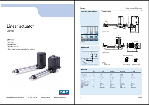
<strong>Linear</strong> <strong>actuator</strong>s DC versions Matrix 1Matrix 1Performance diagramsOrdering keySpeed (mm/s)Current consumption (A)MAX1 – A 0002010,0Type15C7,5Voltage:24 V DC 024 V DC with integrated current cut-off 1105BA5,02,5CBALoad:4 000 N A2 000 N B1 500 N C00 1 000 2 000 3 000 4 000Speed-load diagramSafety factor load conditions4 0003 5003 000Load (N)A pull/pushLoad (N)08 0007 0006 0000 1 000 2 000 3 000 4 000Load (N)Current-load diagramLoad (N)8 0007 0006 000Load (N)Stroke (S):50 mm 050 245100 mm 100 295150 mm 150 345200 mm 200 395250 mm 250 445300 mm 300 495350 mm 350 545400 mm 400 660450 mm 450 710500 mm 500 760550 mm 550 810600 mm 600 860650 mm 650 910700 mm 700 960Other stroke lengths; 50
Matrix 6<strong>Linear</strong> <strong>actuator</strong>s AC versionsSuitable control units and accessoriesDimensional drawingSide view<strong>Linear</strong> <strong>actuator</strong>Matrix 6MAX 6 Integrated control unitEHA 1PHC 1STFPFPSTAPAMS15 12L±2*1361415Hand switchFoot switchDesk switch1 142,5†3129†12 +0,3+0,1†12 +0,3+0,1Mains cable85BConnecting diagramTop view281 1* S < 350 mm; L = S + 215S > 350 mm; L = S + 28028123112120/230 V ACLNPEOperatingdevice40,550LabelRear attachment positionStandard 0° Turned 90°192,5M135Technical dataUnit MAX 6..A.. MAX 6..B.. MAX 6..C..Rated push load N 8 000 4 000 3 000Rated pull load N 6 000 1) 4 000 3 000Speed (full load to no load) mm/s 6 to 7,5 8 to 10 13 to 18Stroke mm 50 to 700 50 to 700 50 to 700Retracted length mm S + 215/280 2) S + 215/280 2) S + 215/280 2)Voltage V AC 120 or 230 120 or 230 120 or 230Power consumption 120 V AC W 150 150 150230 V AC W 145 145 145Current consumption 120 V AC A 1,8 1,8 1,8230 V AC A 0,9 0,9 0,9Duty cycle % 10 (1/9) 10 (1/9) 10 (1/9)Ambient temperature °C 0 to +40 0 to +40 0 to +40Type of protection IP 66S 66S 66SWeight (at 200 mm stroke) kg 4,8 4,5 4,2Color – Grey Grey Grey1) Max load for medical application is 5 000 N2) S < 350 mm; L = S + 215S > 350 mm; L = S + 280<strong>Electro</strong> <strong>Mechanical</strong> <strong>Systems</strong> Limited tel: 0118 981 7391 info@ems-ltd.com www.ems-limited.co.uk2
Magdrive<strong>Linear</strong> <strong>actuator</strong>s DC versionsSuitable control units and accessoriesDimensional drawingL= 1 500 mm†12 +0,3+0,1 †12 +0,3+0,1<strong>Linear</strong> <strong>actuator</strong>MAGDRIVESCU 1SCU 5SCU 9VCU 5VCU 8VCU 9BCU 5BCU 862†3129MagdriveEHA 3STJSTE15 12L = S + 465/489±227151528111128Benefits Slim design Aluminium profile In-line <strong>actuator</strong> Quiet operation High push loadConnecting diagram24 V DC+Plastic bushing for forkhead(hinge delivered separately)251026†10†12Orientation ofrear attachmentStandard 0°90° turned8,7MLegend:S = strokeL = retracted lengthTechnical dataUnit MD22/MD24 MD23/MD25Push load N 6 000 6 000Pull load N 200* (static only) 6 000Speed (full load to no load) mm/s 8,5 to 15 8,5 to 15Stroke mm 50 to 700 50 to 700Retracted length mm S+465 S+489Voltage V DC 24 24Power consumption W N/A N/ACurrent consumption A 7 7Duty cycle % 10 (1/9) 10 (1/9)Ambient temperature °C +10 to +40 +10 to +40Type of protection IP 0/4S 0/4SWeight kg 5,0 5,0Color – Colorless anodized Colorless anodized<strong>Electro</strong> <strong>Mechanical</strong> <strong>Systems</strong> Limited tel: 0118 981 7391 info@ems-ltd.com www.ems-limited.co.uk2
Magforce WSP<strong>Linear</strong> <strong>actuator</strong>s AC versionsConnecting diagramDimensional drawing≈12290PG clamp range†4 – 10<strong>Linear</strong> <strong>actuator</strong>Magforce WSP230 V ACLNPEStroke†10 H84410†56Free-wheel-brake on requestRetracted length = stroke + 230 mmStroke + 25572120†30†12 + + 0,090,04MSide viewBenefits Modular Robust Reliable High speed and/or high load All metal design†20†3010H1125Top view60127≈1089072,51631≈161≈199≈228Rear view†48Technical dataUnit WSP 0510 WSP 1030 WSP 1550 WSP 2650Push load N 500 1 000 1 500 1) 2 600 2)Pull load N 500 1 000 1 500 2 600Speed (at full load) mm/s 50 18 10 5Stroke mm 100 to 700 100 to 700 100 to 700 100 to 700Retracted length mm S+230 S+230 S+230 S+230Voltage V AC 230 230 230 230Power consumption W 230 200 200 230Current consumption A 1,1 1 1 1,1Duty cycle % 25 (2,5/7,5) 25 (2,5/7,5) 25 (2,5/7,5) 25 (2,5/7,5)Ambient temperature °C –10 to +40 –10 to +40 –10 to +40 –10 to +40Type of protection IP 54 54 54 54Weight (at 200 mm stroke) kg 5,5 5,5 5,5 5,5Color – Silver Silver Silver Silver1) Push load allowed up to 650 mm stroke (if S>650 mm, only pull load is allowed)2) Push load allowed up to 500 mm stroke (if S>500 mm, only pull load is allowed)<strong>Electro</strong> <strong>Mechanical</strong> <strong>Systems</strong> Limited tel: 0118 981 7391 info@ems-ltd.com www.ems-limited.co.uk2
<strong>Linear</strong> <strong>actuator</strong>s AC versionsMagforce WSPMagforce WSPPerformance diagramSafety load factor conditionsOrdering keySpeed (mm/s)Stroke (mm)WSP – – –60504030800700600500400Add. guidingrecommendedS = 4FTypeLoad:500 N 05101 000 N 10301 500 N 15502 600 N 2650201000 500 1 000 1 500 2 000 2 500 3 000Load (N)Speed-load diagramWSP 0510-200WSP 1030-200WSP 1550-200WSP 2650-2003002001000Standardguiding1 2 3 4 5 6 7 8Load (kN)Bending of spindleS = safety factor Euler 3Stroke (S):100 mm 100200 mm 200300 mm 300400 mm 400500 mm 500600 mm 600700 mm 700Option 1:No option 01Others*XXOption 2:No option 0Free wheel brake on push load, 1028, 6228AFree wheel brake on pull load, 1028, 0002BFriction brake for pull/push load, 1028, 7851COptionsOption 3:No option 0Limit switch 1Options shown in italics are only available on request.Minimum quantities or additional costs apply for option 1 if shown in italics. For option 2 and 3 please contact your SKF representative.Example for ordering an <strong>actuator</strong> without any options: WSP1030–100–01.Example for ordering an <strong>actuator</strong> with option limit switch: WSP1030–100–01–01 (01= with limit switch).* Example for others XX: Add. guiding bush - L=S+280 mm, protection tube made out of stainless steel, bronze nut, low temp grease –30°,extended motorshaft, rear attachment hole turned 90°, without rear attachment; motor turned 90°.Spare parts4 holes threadM 6 9 mm deepDescription Designation Order N°†1211 312015Extended motor shaftRetracted length = stroke + 203 mmRear screw fixing25Limit switch 100 mm stroke 1043,0209–100 M/0126964Limit switch 200 mm stroke 1043,0209–200 M/0126965Limit switch 300 mm stroke 1043,0209–300 M/0126966Limit switch 400 mm stroke 1043,0209–400 M/0126967Limit switch 500 mm stroke 1043,0209–500 M/0126968Limit switch 600 mm stroke 1043,0209–600 M/0126969® SKF is a registered trademark of the SKF Group© SKF Group 2012The contents of this publication are the copyright of the publisher and may not be reproduced (even extracts) unless prior written permissionis granted. Every care has been taken to ensure the accuracy of the information contained in this publication but no liability can beaccepted for any loss or damage whether direct, indirect or consequential arising out of the use of the information contained herein.PUB L5321,2110 EN · April 20123<strong>Electro</strong> <strong>Mechanical</strong> <strong>Systems</strong> Limited tel: 0118 981 7391 info@ems-ltd.com www.ems-limited.co.uk
<strong>Linear</strong> <strong>actuator</strong>s AC versionsMagforce DSPMagforce DSPPerformance diagramSafety load factor conditionsOrdering keySpeed (mm/s)Stroke /mm)DSP – – –60504030800700600500400Add. guidingrecommendedS = 4FTypeLoad:1 000 N 10102 500 N 25303 200 N 32504 500 N 4550201000 1 000 2 000 3 000 4 000 5 000Load (N)3002001000Standardguiding0 1 2 3 4 5 6 7 8Load (kN)Stroke (S):100 mm 100200 mm 200300 mm 300400 mm 400500 mm 500600 mm 600700 mm 700Speed-load diagramDSP 1010-200DSP 2530-200DSP 3250-200DSP 4550-200Bending of spindleS = safety factor Euler 3Option 1:No option 01Others*XXOption 2:No option 0Free wheel brake on push load, 1028, 6226AFree wheel brake on pull load, 1028, 0002BFriction brake for pull/push load, 1028, 7851COptionsOption 3:No option 0Limit switch 1Options shown in italics are only available on request.Minimum quantities or additional costs apply for option 1 if shown in italics. For option 2 and 3 please contact your SKF representative.Example for ordering an <strong>actuator</strong> without any options: DSP1010–100–01.Example for ordering an <strong>actuator</strong> with option limit switch: DSP1010–100–01–01 (01= with limit switch).* Example for others XX: Add. guiding bush - L=S+280 mm, protection tube made out of stainless steel, bronze nut, low temp grease -30°,extended motorshaft, rear attachment hole turned 90°, without rear attachment; motor turned 90°.4 holes threadM6 ¥ 9 mm deep1525Spare parts1131†1220Retracted length = stroke + 203 mmDesignation Order N°Extended motor shaftRear screw fixingLimit switch 100 mm stroke ZAC–1043,0210–0100 M/0126970Limit switch 200 mm stroke ZAC–1043,0210–0200 M/0126971Limit switch 300 mm stroke ZAC–1043,0210–0300 M/0126972Limit switch 400 mm stroke ZAC–1043,0210–0400 M/0126973Limit switch 500 mm stroke ZAC–1043,0210–0500 M/0126974Limit switch 600 mm stroke ZAC–1043,0210–0600 M/0126975® SKF is a registered trademark of the SKF Group© SKF Group 2012The contents of this publication are the copyright of the publisher and may not be reproduced (even extracts) unless prior written permissionis granted. Every care has been taken to ensure the accuracy of the information contained in this publication but no liability can beaccepted for any loss or damage whether direct, indirect or consequential arising out of the use of the information contained herein.PUB L5321,2120 EN · April 20123<strong>Electro</strong> <strong>Mechanical</strong> <strong>Systems</strong> Limited tel: 0118 981 7391 info@ems-ltd.com www.ems-limited.co.uk
Magforce ASM<strong>Linear</strong> <strong>actuator</strong>s DC versionsConnecting diagramDimensional drawing† 80† 78<strong>Linear</strong> <strong>actuator</strong>12/24 V DC+†10 H8† 562 x 1,5 mm 2 x 500 mm†30+ 0,09†12 + 0,04Magforce ASM1044Free-wheel-brake on request72120MStrokeRetracted length = stroke + 230 mmStroke + 255ASMSide viewBenefits Modular†20†3010H112516RobustReliableHigh speed and/or high loadAll metal designTop view≈10372,5≈225≈203≈16531Rear viewLegend:S = strokeL = retracted length†48Technical dataUnit ASM 1010 ASM 2030 ASM 3030 ASM 4050Push load N 1 000 2 000 1) 3 000 2) 4 000 3)Pull load N 1 000 2 000 3 000 4 000Speed (at full load) 12 V DC mm/s 50 17 8 524 V DC mm/s 45 18 8 5Stroke mm 100 to 700 100 to 700 100 to 700 100 to 700Retracted length mm S+230 S+230 S+230 S+230Voltage V DC 12 or 24 12 or 24 12 or 24 12 or 24Power consumption 12 V DC W 192 168 168 16824 V DC W 192 144 168 168Current consumption 12 V DC A 16 14 14 1424 V DC A 8 6 7 7Duty cycle % 10 (1/9) 10 (1/9) 10 (1/9) 10 (1/9)Ambient temperature °C –10 to +40 –10 to +40 –10 to +40 –10 to +40Type of protection IP 44 44 44 44Weight kg 5 5 5 5Color – Silver Silver Silver Silver1) Push load allowed up to 600 mm stroke (if S>600 mm, only pull load is allowed)2) Push load allowed up to 450 mm stroke (if S>450 mm, only pull load is allowed)3) Push load allowed up to 400 mm stroke (if S>400 mm, only pull load is allowed)<strong>Electro</strong> <strong>Mechanical</strong> <strong>Systems</strong> Limited tel: 0118 981 7391 info@ems-ltd.com www.ems-limited.co.uk2
<strong>Linear</strong> <strong>actuator</strong>s DC versionsMagforce ASMMagforce ASMPerformance diagramsOrdering keySpeed (mm/s)Speed (mm/s)ASM – – –80807070Type6050403020100 1 000 2 000 3 000 4 000Load (N)Speed-load diagram at 12 V DCASM 1010ASM 2030ASM 3030ASM 40506050403020100 1 000 2 000 3 000 4 000Load (N)Speed-load diagram at 24 V DCLoad:1 000 N 10102 000 N 20303 000 N 30304 000 N 4050Stroke (S):100 mm 100200 mm 200300 mm 300400 mm 400500 mm 500600 mm 600700 mm 700Option 1:12 V DC 0124 V DC 02Others*XXSafety factor load conditionsStroke (mm)800Add. guiding700recommended600500S = 4400FOption 2:No option 0Free wheel brake on push load, 1028,6226AFree wheel brake on pull load, 1028, 0002BFriction brake for pull/push load, 1028, 7851COption 3:No option 0Limit switch 1Options shown in italics are only available on request.Minimum quantities or additional costs apply for option 1 if shown in italics. For option 2 and 3 please contact your SKF representative.Example for ordering an <strong>actuator</strong> without any options: ASM1010–100–01.Example for ordering an <strong>actuator</strong> with option limit switch: ASM1010–100–01–01 (01= with limit switch).* Example for others XX: Add. guiding bush - L=S+280 mm, protection tube made out of stainless steel, bronze nut, low temp grease –30°,extended motorshaft, rear attachment hole turned 90°, without rear attachment; motor turned 90°.300200100Standardguiding01 2 3 4 5 6 7 8Load (kN)Bending of spindleS = safety factor Euler 3Spare partsDesignation Order N°Limit switch 100 mm stroke ZAC–1043,0210–0100 M/0126970Limit switch 200 mm stroke ZAC–1043,0210–0200 M/0126971Limit switch 300 mm stroke ZAC–1043,0210–0300 M/0126972Limit switch 400 mm stroke ZAC–1043,0210–0400 M/0126973Limit switch 500 mm stroke ZAC–1043,0210–0500 M/0126974Limit switch 600 mm stroke ZAC–1043,0210–0600 M/0126975® SKF is a registered trademark of the SKF Group© SKF Group 2012The contents of this publication are the copyright of the publisher and may not be reproduced (even extracts) unless prior written permissionis granted. Every care has been taken to ensure the accuracy of the information contained in this publication but no liability can beaccepted for any loss or damage whether direct, indirect or consequential arising out of the use of the information contained herein.PUB L5321,2130 EN · April 20123<strong>Electro</strong> <strong>Mechanical</strong> <strong>Systems</strong> Limited tel: 0118 981 7391 info@ems-ltd.com www.ems-limited.co.uk
Magforce STW<strong>Linear</strong> <strong>actuator</strong>s AC versionsDimensional drawing54 †116 56†116†14035PG 16 clamprange†8–15<strong>Linear</strong> <strong>actuator</strong>†40Stroke174Retracted length = stroke + 273Stroke + 293† 16F779692095 67Rear viewMagforce STWSide viewLimit switches or potentiometer on request†6520M32 x 1,531Top viewConnecting diagrams230 V ACL1NPE230 V ACL1NPEK1K2K2K1K2K1K2K1CCMW V UMW V U2 1 3 5 4 6Y X ZY X ZWith optional limit switchTechnical dataUnit STW 5007 STW 7010 STW 10020 STW 15040Push load N 5 000 7 000 10 000 15 000Pull load N 5 000 7 000 10 000 15 000Speed (at full load) mm/s 12 8 4 2Stroke mm 100 to 700 100 to 700 100 to 700 100 to 700Retracted length mm S+273 S+273 S+273 S+273Voltage V AC 230 230 230 230Power consumption W 700 710 710 750Current consumption A 3,3 3,5 3,5 3,5Duty cycle % 15 (1,5/8,5) 10 (1/9) 10 (1/9) 10 (1/9)Ambient temperature °C –10 to +40 –10 to +40 –10 to +40 –10 to +40Type of protection IP 54 54 54 54Weight (at 200 mm stroke) kg 14,6 14,6 14,6 14,6Color – Silver Silver Silver Silver<strong>Electro</strong> <strong>Mechanical</strong> <strong>Systems</strong> Limited tel: 0118 981 7391 info@ems-ltd.com www.ems-limited.co.uk2
<strong>Linear</strong> <strong>actuator</strong>s AC versionsMagforce STWMagforce STWPerformance diagramSafety load factor conditionsOrdering key1412Speed (mm/s)Stroke (mm)800S = 4700Add. bearingrecommendedFSTW – – –10864200 5 000 10 000 15 000Load (N)Speed-load diagramSTW 5007-200STW 7010-200STW 10020-200STW 15040-2006005004003002001000Standardguiding0 2 4 6 8 10 14 16 18Load (kN)Bending of spindleS = safety factor Euler 3TypeLoad:5 000 N 050077 000 N 0701010 000 N 1002015 000 N 15040Stroke (S):100 mm 100200 mm 200300 mm 300400 mm 400500 mm 500600 mm 600700 mm 700Option 1:No option 01Others*XXOptionsOption 2:No option 0Adapterbolt M18 1031,0106EFork head (including adapterbolt) 1051,9038FOption 3:No option 0Limit switch 1Potentiometer (1 000 Ω) 2Encoder 1063,0020 3Options shown in italics are only available on request.StrokeStroke + 2909 18 9Minimum quantities or additional costs apply for option 1 if shown in italics. For option 2 and 3 please contact your SKF representative.Example for ordering an <strong>actuator</strong> without any options: STW05007–100–01.Example for ordering an <strong>actuator</strong> with option fork head: STW05007–100–01–F0 (F0= with fork head).* Example for others XX: Back up nut, extended motor shaft, low temperature grease...M18 x 2,540 SW 30M32 x 2,5221836SW 27SW 30†4036Spare parts1725StrokeStroke + 377Designation Order N°Adapter82Stroke + 419Front attachmentAdapter bolt ZBE–1031,0106 M/0125265Fork head ZBE–1051,9038 M/0124705® SKF is a registered trademark of the SKF Group© SKF Group 2012The contents of this publication are the copyright of the publisher and may not be reproduced (even extracts) unless prior written permissionis granted. Every care has been taken to ensure the accuracy of the information contained in this publication but no liability can beaccepted for any loss or damage whether direct, indirect or consequential arising out of the use of the information contained herein.PUB L5321,2310 EN · April 20123<strong>Electro</strong> <strong>Mechanical</strong> <strong>Systems</strong> Limited tel: 0118 981 7391 info@ems-ltd.com www.ems-limited.co.uk
Magforce STD<strong>Linear</strong> <strong>actuator</strong>s AC versionsDimensional drawing54†116 56†116† 14035PG 16 clamprange†8–15<strong>Linear</strong> <strong>actuator</strong>Magforce STD†40StrokeSide view† 16 F7174Retracted length = stroke + 273Stroke + 293Limit switches or potentiometer on request75692095 67Rear view†6520M32 x 1,531Top viewConnecting diagrams3x400 V ACL1L2L3NPEK1K23x400 V ACL1L2L3NPEK1K2K1K2K2K1K1K2K2K11 3 21 3 2M758M7582 1 3 5 4 66 9 46 9 4Limit switchWith optional limit switchTechnical dataUnit STD 10007 STD 12010 STD 15020 STD 15040Rated push load N 10 000 12 000 15 000 15 000Rated pull load N 10 000 12 000 15 000 15 000Speed (at full load) mm/s 10 7 4 2Stroke mm 100 to 700 100 to 700 100 to 700 100 to 700Retracted length mm S+273 S+273 S+273 S+273Voltage V AC 3400 3400 3400 3400Power consumption W 920 800 700 500Current consumption A 1,8 1,7 1,6 1,4Duty cycle % 25 (2,5/7,5) 10 (1/9) 10 (1/9) 10 (1/9)Ambient temperature °C –10 to +40 –10 to +40 –10 to +40 –10 to +40Type of protection IP 54 54 54 54Weight (at 200 mm stroke) kg 14,6 14,6 14,6 14,6Color – Silver Silver Silver Silver<strong>Electro</strong> <strong>Mechanical</strong> <strong>Systems</strong> Limited tel: 0118 981 7391 info@ems-ltd.com www.ems-limited.co.uk2
<strong>Linear</strong> <strong>actuator</strong>s AC versionsMagforce STDMagforce STDPerformance diagramSafety load factor conditionsOrdering keySpeed (mm/s)Stroke (mm)STD – – –141210864200 5 000 10 000 15 000Load (N)Speed-load diagramSTD 10007-200STD 12010-200STD 15020-200STD 15040-2008007006005004003002001000S = 4StandardguidingAdd. bearingrecommended0 2 4 6 8 10 12 14 16Load (kN)Bending of spindleS = safety factor Euler 3FTypeLoad:10 000 N 1000712 000 N 1201015 000 N / 4 mm/s 1502015 000 N / 2 mm/s 15040Stroke (S):100 mm 100200 mm 200300 mm 300400 mm 400500 mm 500600 mm 600700 mm 700Option 1:No option 01Others*XXOption 2:No option 0Adapterbolt M18 1031,0106EFork head (including adapterbolt) 1051,9038FOptionsOption 3:No option 0Limit switch 1Potentiometer (1 000 Ω) 2Encoder 1063,0020 3Options shown in italics are only available on request.M18 x 2,5Stroke Stroke + 29040 SW 30M32 x 1,5†4036 9 18 922 3618SW 27SW 30Minimum quantities or additional costs apply for option 1 if shown in italics. For option 2 and 3 please contact your SKF representative.Example for ordering an <strong>actuator</strong> without any options: STD10007–100–01.Example for ordering an <strong>actuator</strong> with option fork head: STD10007–100–01–F0 (F0=with fork head).* Example for others XX: Back up nut, extended motor shaft, low temperature grease, add. guiding bush...172582StrokeStroke + 377Stroke + 419Spare partsDesignation Order N°AdapterFork headAdapter bolt ZBE–1031,0106 M/0125265Fork head ZBE–1051,9038 M/0124705® SKF is a registered trademark of the SKF Group© SKF Group 2012The contents of this publication are the copyright of the publisher and may not be reproduced (even extracts) unless prior written permissionis granted. Every care has been taken to ensure the accuracy of the information contained in this publication but no liability can beaccepted for any loss or damage whether direct, indirect or consequential arising out of the use of the information contained herein.PUB L5321,2320 EN · April 20123<strong>Electro</strong> <strong>Mechanical</strong> <strong>Systems</strong> Limited tel: 0118 981 7391 info@ems-ltd.com www.ems-limited.co.uk
Magforce STG<strong>Linear</strong> <strong>actuator</strong>s DC versionsDimensional drawing†113 61†113Cable length max. 500 mm†14035†40<strong>Linear</strong> <strong>actuator</strong>Magforce STGStrokeM32 x 1,5† 16 F7173Retracted length = stroke + 273Stroke + 293Free-wheel-brake on request95 67Side viewRear viewCable length max. 500 mm Limit switches or potentiometer on request†65756920Benefits Modular31Top viewRobustReliableHigh speed and/or high loadConnecting diagrams24 V DC +-24 V DC +-All metal designK1K2K1K2K1K2K2K1BrownBlueBrownBlueMM2 1 3 5 4 6With optional limit switchLimit switchTechnical dataUnit STG 10007 STG 12010 STG 15020 STG 15040Rated push load N 10 000 12 000 15 000 15 000Rated pull load N 10 000 12 000 15 000 15 000Speed (at full load) mm/s 14 11 5 3Stroke mm 100 to 700 100 to 700 100 to 700 100 to 700Retracted length mm S+273 S+273 S+273 S+273Voltage V DC 24 24 24 24Power consumption W 840 840 768 528Current consumption A 35 35 32 22Duty cycle % 10 (1/9) 10 (1/9) 10 (1/9) 10 (1/9)Ambient temperature °C –10 to +40 –10 to +40 –10 to +40 –10 to +40Type of protection IP 54 54 54 54Weight (at 200 mm stroke) kg 14,6 14,6 14,6 14,6Color – Silver Silver Silver Silver<strong>Electro</strong> <strong>Mechanical</strong> <strong>Systems</strong> Limited tel: 0118 981 7391 info@ems-ltd.com www.ems-limited.co.uk2
<strong>Linear</strong> <strong>actuator</strong>s DC versionsMagforce STGMagforce STGPerformance diagramOrdering keySpeed (mm/s)201816141210864200 5 000 10 000 15 000Load (N)Speed-load diagramSafety load factor conditionsStroke (mm)800FS = 4Add. guiding700recommended600500400300200Standardguiding10000 2 4 6 8 10 12 14 16Load (kN)STG 10007–300STG 12010–300STG 15020–300STG 15040–300TypeLoad:10 000 N 1000712 000 N 1201015 000 N / 5 mm/s 1502015 000 N / 3 mm/s 15040Stroke (S):100 mm 100200 mm 200300 mm 300400 mm 400500 mm 500600 mm 600700 mm 700Option 1:No option 01Others*XXOption 2:No option 0Adapterbolt M18 1031,0106EFork head (including adapterbolt) 1051,9038FMagnetic brake (1,4 Nm) 1031, 0219GOption 3:No option 0Limit switch 1Potentiometer (1 000 Ω) 2Encoder 1063,0020 3Options shown in italics are only available on request.STG – – –Minimum quantities or additional costs apply for option 1 if shown in italics. For option 2 and 3 please contact your SKF representative.Example for ordering an <strong>actuator</strong> without any options: STG10007–100–01.Example for ordering an <strong>actuator</strong> with option fork head: STG10007–100–01–F0 (F0= with fork head).*Example for others XX: Back up nut, extended motor shaft, low temperature grease...Bending of spindle S = safety factor Euler 3OptionsSpare partsDesignation Order N°M18 x 2,5Stroke Stroke + 29040 SW 30M32 x 1,536 9 18 922 3618SW 27SW 30Adapter bolt ZBE–1031,0106 M/0125265Fork head ZBE–1051,9038 M/0124705StrokeStroke + 3771725Stroke + 41982AdapterFork head® SKF is a registered trademark of the SKF Group© SKF Group 2012The contents of this publication are the copyright of the publisher and may not be reproduced (even extracts) unless prior written permissionis granted. Every care has been taken to ensure the accuracy of the information contained in this publication but no liability can beaccepted for any loss or damage whether direct, indirect or consequential arising out of the use of the information contained herein.PUB L5321,2330 EN · April 20123<strong>Electro</strong> <strong>Mechanical</strong> <strong>Systems</strong> Limited tel: 0118 981 7391 info@ems-ltd.com www.ems-limited.co.uk
Magforce SKD<strong>Linear</strong> <strong>actuator</strong>s AC versionsDimensional drawing170†130<strong>Linear</strong> <strong>actuator</strong>Magforce SKD42†16†40†65L = S + 309 ±2174114,5219†16F740256995†14062Limit switch orpotentiometerL = S + 406 ±2Side viewRear viewBenefits Modular Robust Reliable High speed and/or high load All metal designLegend:S = strokeL = retracted lengthConnecting diagrams3x400 V ACL1L2L3NPEK1K23x400 V ACL1L2L3NPEK1K2K1K2K2K1K1K2K2K11 3 21 3 2M758M7582 1 3 5 4 66 9 46 9 4Limit switchWith optional limit switchTechnical dataUnit SKD 10007 SKD 12010 SKD 15020 SKD 15040Rated push load N 10 000 12 000 15 000 15 000Rated pull load N 10 000 12 000 15 000 15 000Speed (at full load) mm/s 25 18 11 5Stroke mm 100 to 700 100 to 700 100 to 700 100 to 700Retracted length mm S+406 S+406 S+406 S+406Voltage V AC 3400 3400 3400 3400Power consumption W 920 800 750 600Current consumption A 1,8 1,7 1,6 1,5Duty cycle % 25 (2,5/7,25) 10 (1/9) 10 (1/9) 10 (1/9)Ambient temperature °C –10 to +40 –10 to +40 –10 to +40 –10 to +40Type of protection IP 54 54 54 54Weight (at 200 mm stroke) kg 14,6 14,6 14,6 14,6Color – Silver Silver Silver Silver<strong>Electro</strong> <strong>Mechanical</strong> <strong>Systems</strong> Limited tel: 0118 981 7391 info@ems-ltd.com www.ems-limited.co.uk2
<strong>Linear</strong> <strong>actuator</strong>s AC versionsMagforce SKDMagforce SKDPerformance diagramOrdering keySpeed (mm/s)353025201510500 5 000 10 000 15 000Load (N)Speed-load diagramSKD 10007–200SKD 12010–200SKD 15020–200SKD 15040–200SKD – – –TypeLoad:10 000 N 1000712 000 N 1201015 000 N / 11 mm/s 1502015 000 N / 5 mm/s 15040Stroke (S):100 mm 100200 mm 200300 mm 300400 mm 400500 mm 500600 mm 600700 mm 700Option 1:No option 01Others*XXOption 2:No option 0Magnetic brake (1,4 Nm) 1031,0219GOption 3:No option 0Limit switch 1Potentiometer (1 000 Ω) 2Encoder 1063,0020 3Options shown in italics are only available on request.Minimum quantities or additional costs apply for option 1 if shown in italics. For options 2 and 3, please contact your SKF representative.Example for ordering an <strong>actuator</strong> without any options: SKD10007–100–01.Example for ordering an <strong>actuator</strong> with option limit switch: SKD10007–100–01–01 (01=limit switch).* Example for others XX: Extended motor shaft,...® SKF is a registered trademark of the SKF Group© SKF Group 2012The contents of this publication are the copyright of the publisher and may not be reproduced (even extracts) unless prior written permissionis granted. Every care has been taken to ensure the accuracy of the information contained in this publication but no liability can beaccepted for any loss or damage whether direct, indirect or consequential arising out of the use of the information contained herein.PUB MT/P8 10391 EN · April 20123<strong>Electro</strong> <strong>Mechanical</strong> <strong>Systems</strong> Limited tel: 0118 981 7391 info@ems-ltd.com www.ems-limited.co.uk
Magforce SKG<strong>Linear</strong> <strong>actuator</strong>s DC versionsDimensional drawing†110Cable length max. 500 mm<strong>Linear</strong> <strong>actuator</strong>42†16 †16 F7†40†65220N75†14040Magforce SKG174253595L=S+309 ±2L=S+406 ±2Side viewRear viewBenefits Modular RobustLegend:S = strokeL = retracted lengthReliableHigh speed and/or high loadConnecting diagrams24 V DC +-24 V DC +-All metal designK1K2K1K2K1K2K2K1BrownBlueBrownBlueMM2 1 3 5 4 6With optional limit switchLimit switchTechnical dataUnit SKG 6005 SKG 10010 SKG 13020 SKG 15040Rated push load N 6 000 10 000 13 000 15 000Rated pull load N 6 000 10 000 13 000 15 000Speed (at full load) mm/s 55 27 15 8Stroke mm 100 to 700 100 to 700 100 to 700 100 to 700Retracted length mm S+406 S+406 S+406 S+406Voltage V DC 24 24 24 24Power consumption W N/A 720 672 –Current consumption A N/A 30 28 –Duty cycle % 10 (1/9) 10 (1/9) 10 (1/9) 10 (1/9)Ambient temperature °C –10 to +40 –10 to +40 –10 to +40 –10 to +40Type of protection IP 54 54 54 54Weight (at 200 mm stroke) kg 14,6 14,6 14,6 14,6Color – Silver Silver Silver Silver<strong>Electro</strong> <strong>Mechanical</strong> <strong>Systems</strong> Limited tel: 0118 981 7391 info@ems-ltd.com www.ems-limited.co.uk2
<strong>Linear</strong> <strong>actuator</strong>s DC versionsMagforce SKGMagforce SKGPerformance diagramOrdering key8070605040302010Speed (mm/s)00 5 000 10 000 15 000Load (N)Speed-load diagramSKG 6005–200SKG 10010–200SKG 13020–200SKG 15040–200TypeLoad:6 000 N 0600510 000 N 1001013 000 N 1302015 000 N 15040Stroke (S):100 mm 100200 mm 200300 mm 300400 mm 400500 mm 500600 mm 600700 mm 700Option 1:No option 01Others*XXOption 2:No option 0Magnetic brake (1,4 Nm) 1031, 0219GOption 3:No option 0Limit switch 1Potentiometer (1 000 Ω) 2Encoder 1063,0020 3Options shown in italics are only available on request.SKG – – –Minimum quantities or additional costs apply for option 1 if shown in italics. For option 2 and 3 please contact your SKF representative.Example for ordering an <strong>actuator</strong> without any options: SKG06005–100–01.Example for ordering an <strong>actuator</strong> with option limit switch: SKG06005–100–01–01 (01=limit switch).* Example for others XX: Extended motor shaft,...® SKF is a registered trademark of the SKF Group© SKF Group 2012The contents of this publication are the copyright of the publisher and may not be reproduced (even extracts) unless prior written permissionis granted. Every care has been taken to ensure the accuracy of the information contained in this publication but no liability can beaccepted for any loss or damage whether direct, indirect or consequential arising out of the use of the information contained herein.PUB MT/P8 10392 EN · April 20123<strong>Electro</strong> <strong>Mechanical</strong> <strong>Systems</strong> Limited tel: 0118 981 7391 info@ems-ltd.com www.ems-limited.co.uk
Magforce SKS/SKA<strong>Linear</strong> <strong>actuator</strong>s AC versionsConnecting diagramDimensional drawing≈ 2033x400 V ACL1L2L3NPEF1F2PG 16 clamprange†8–15145<strong>Linear</strong> <strong>actuator</strong>S2upK1K2S1downK2K1K2K1† 25≈ 302Magforce SKS/SKAW1 V1 U1M+-AC†85†60StrokeRetracted length = stroke + 465Stroke + 525210† 25 F8Benefits Modular Robust Reliable High speed and/or high load All metal design†85†60312261,591Side viewTop view30175 90Technical dataUnit SKS/SKA 15404 SKS/SKA 20406 SKS/SKA 25412 SKS/SKA 30423Rated push load N 15 000 20 000 25 000 30 000Rated pull load N 15 000 20 000 25 000 30 000Speed (at full load) mm/s 45 35 17 9Stroke mm 100 to 700 100 to 700 100 to 700 100 to 700Retracted length mm S+465 S+465 S+465 S+465Voltage V AC 3400 3400 3400 3400Power consumption W 1 700 1 650 1 300 1 200Current consumption A 3,3 3,5 2,8 3,0Duty cycle % 10 (1/9) 10 (1/9) 10 (1/9) 10 (1/9)Ambient temperature °C –10 to +40 –10 to +40 –10 to +40 –10 to +40Type of protection IP 54 54 54 54Weight (at 200 mm stroke) kg 30 30 30 30Color – Silver Silver Silver Silver<strong>Electro</strong> <strong>Mechanical</strong> <strong>Systems</strong> Limited tel: 0118 981 7391 info@ems-ltd.com www.ems-limited.co.uk2
<strong>Linear</strong> <strong>actuator</strong>s AC versionsMagforce SKS/SKAMagforce SKS/SKAPerformance diagramOrdering key60Speed (mm/s)SK S – –504030TypeOption:No optionS201000 5 000 10 000 15 000 20 000 25 000 30 000Load (N)Speed-load diagramSKS 15404-300SKS 20406-300SKS 25412-300SKS 30423-300Load:15 000 N 1540420 000 N 2040625 000 N 2541230 000 N 30423Stroke (S):100 mm 100200 mm 200300 mm 300400 mm 400500 mm 500600 mm 600700 mm 700Customer option:Standard 01Others (extended motor shaft, back-up nut, ...)XXOptions shown in italics are only available on demand. Contact SKF for more information on minimum quantities and additional costs.SK A – –TypeOption:With limit switches and/or potentiometerALoad:15 000 N 1540420 000 N 2040625 000 N 2541230 000 N 30423Stroke (S):100 mm 100200 mm 200300 mm 300400 mm 400500 mm 500600 mm 600700 mm 700Customer option:Standard with limit switch and potentiometer 1k-ohm 01Standard with limit switch 02Others (extended motor shaft, back-up nut, ...)XXOptions shown in italics are only available on demand. Contact SKF for more information on minimum quantities and additional costs.® SKF is a registered trademark of the SKF Group© SKF Group 2010The contents of this publication are the copyright of the publisher and may not be reproduced (even extracts) unless prior written permissionis granted. Every care has been taken to ensure the accuracy of the information contained in this publication but no liability can beaccepted for any loss or damage whether direct, indirect or consequential arising out of the use of the information contained herein.Printed in Sweden on environmentally friendly paper.PUB L5321,2380 EN · May 20103<strong>Electro</strong> <strong>Mechanical</strong> <strong>Systems</strong> Limited tel: 0118 981 7391 info@ems-ltd.com www.ems-limited.co.uk
Magforce SLS<strong>Linear</strong> <strong>actuator</strong>s AC versionsConnecting diagramDimensional drawing1913x400 V ACL1L2L3NPEF1F2<strong>Linear</strong> <strong>actuator</strong>Magforce SLSS2upK1K2S1downK2K1K2K1W1 V1 U1100† 3060 45Stroke + 364 / +2Stroke + 446 / +2† 3080M+-ACSide view22890Benefits Modular Robust Reliable High speed and/or high load All metal design†8025†110Top view†200†15762381308Rear view65238Technical dataUnit SLS 18006 SLS 34013 SLS 50020 SLS 50028 SLS 50050Rated push load N 18 000 34 000 50 000 50 000 50 000Rated pull load N 18 000 34 000 50 000 50 000 50 000Speed (at full load) mm/s 74 36 23 16 9Stroke mm 100 to 700 100 to 700 100 to 700 100 to 700 100 to 700Retracted length mm S+446 S+446 S+446 S+446 S+446Voltage V AC 3400 3400 3400 3400 3400Power consumption W 3 000 3 000 3 000 2 200 1 900Current consumption A 3,9 3,9 3,9 3,5 3,6Duty cycle % 10 (1/9) 10 (1/9) 10 (1/9) 10 (1/9) 10 (1/9)Ambient temperature °C –10 to +40 –10 to +40 –10 to +40 –10 to +40 –10 to +40Type of protection IP 54 54 54 54 54Weight kg 40 40 40 40 40Color – Silver Silver Silver Silver Silver<strong>Electro</strong> <strong>Mechanical</strong> <strong>Systems</strong> Limited tel: 0118 981 7391 info@ems-ltd.com www.ems-limited.co.uk2
<strong>Linear</strong> <strong>actuator</strong>s AC versionsMagforce SLSMagforce SLSPerformance diagramOrdering keySpeed (mm/s)10090807060504030201000 10 000 20 000 30 000 40 000 50 000Load (N)Speed-load diagramSLS 18006SLS 34013SLS 50020SLS 50028SLS 50050TypeLoad:18 000 N 1800634 000 N 3401350 000 N / 23 mm/s 5002050 000 N / 16 mm/s 5002850 000 N / 9 mm/s 50050SLS – –Stroke (S):100 mm 100200 mm 200300 mm 300400 mm 400500 mm 500600 mm 600700 mm 700Customer option:Standard 01Others (extended motor shaft, ...)XXOptions shown in italics are only available on demand. Contact SKF for more information on minimum quantities and additional costs.® SKF is a registered trademark of the SKF Group© SKF Group 2010The contents of this publication are the copyright of the publisher and may not be reproduced (even extracts) unless prior written permissionis granted. Every care has been taken to ensure the accuracy of the information contained in this publication but no liability can beaccepted for any loss or damage whether direct, indirect or consequential arising out of the use of the information contained herein.Printed in Sweden on environmentally friendly paper.PUB MT/P8 10393 EN · May 20103<strong>Electro</strong> <strong>Mechanical</strong> <strong>Systems</strong> Limited tel: 0118 981 7391 info@ems-ltd.com www.ems-limited.co.uk
CARE 33<strong>Linear</strong> <strong>actuator</strong>s DC versionsSuitable control units and accessoriesDimensional drawing †64<strong>Linear</strong> <strong>actuator</strong>CARE 33CARE 33A 24VCARE 33M 24VCARE 33H 24VCAES 31CEHA 3STJSTEVCU 5VCU 8VCU 9BCU 5BCU 8CAED 5-24RCAXC 33 1)Dual encoder 2)2633 59†22†121333L=S+ (150/162/193)*†50548,2252033 140Rearattachmentorientation view.Benefits Silent operation Multiple speed/load variants Easy to adjust limit switches Different attachment options Digital encoder feedback1) See page 3942) See page 397Connecting diagram12/24 V DC+3126M126,122E 12,7L=S+1933811L=S+1621013 L=S+150* Dimension depends on selected front attachment3 1 22LimitswitchLimitswitch1 2MLegend:S = strokeL = retracted lengthTechnical dataUnit CARE 33A CARE 33M CARE 33HPush load N 2 000 1 400 800Pull load N 2 000 1 400 800Speed (full load to no load) mm/s 8 to 12 1) 16 to 22 1) 32 to 45 1)Stroke mm 50 to 300 50 to 500 50 to 500Retracted length mm S+150/162/193 2) S+150/162/193 2) S+150/162/193 2)Voltage V DC 24 24 24Power consumption W N/A N/A N/ACurrent consumption A 3,5 3,5 3,5Duty cycle % 15 20 30Ambient temperature °C –10 to +50 –10 to +50 –10 to +50Type of protection IP 44/65 44/65 44/65Weight kg 1,5 to 2,0 1,5 to 2,0 1,5 to 2,0Color – Black Black Black1) Depending on selected motor2) Dimension depends on selected front attachment<strong>Electro</strong> <strong>Mechanical</strong> <strong>Systems</strong> Limited tel: 0118 981 7391 info@ems-ltd.com www.ems-limited.co.uk2
<strong>Linear</strong> <strong>actuator</strong>s DC versions CARE 33CARE 33Performance diagramsSpeed (mm/s)504540353025201510500 200 400 600 800 1 000 1 200 1 400 1 600 1 800 2 000Load (N)Speed-load diagramCurrent consumption (A)5,04,54,03,53,02,52,01,51,00,500 200 400 600 800 1 000 1 200 1 400 1 600 1 800 2 000Load (N)Current-load diagramOrdering keyC A R E 3 3TypeLoad:2 000 N A1 400 N M800 N HStroke (S):50 mm 050100 mm 100150 mm 150200 mm 200300 mm 300400 mm (not possible for CARE 33A) 400500 mm (not possible for CARE 33A) 500Other stroke lengths ---Front attachment:Hole, †=12,0 mm 1Hole, †=12,7 mm 2Hole 10 mm, slot 6,1 mm (retracted length, L=S+162 mm) 3Male thread M12 (retracted length, L=S+193 mm) 4AMHV (mm/s)V (mm/s)V (mm/s)I (A)Rear attachment:Hole, †=12,0 mm 1Hole, †=12,7 mm 2Hole, †=8,0 mm 3Hole, †=10,0 mm 4Type of protection:IP65 1IP44 2Feedback:No option 0Dual encoder 1Cable/Connection plug:Straight, 2,0 m, no plug 1Coiled, 2,0 m, jack plug 2Straight, 2,0 m, DIN 8 plug (for 2-channel encoder) 3Straight, 2,0 m, jack plug 5Straight, 2,5 m, DIN8 plug BCU/VCU (ONLY available for CARE 33A)C5Orientation of rear attachment:0° 00015° clockwise 01530° clockwise 03045° clockwise 04560° clockwise 06075° clockwise 07590° clockwise 090105° clockwise 105120° clockwise 120130° clockwise 130150° clockwise 150165° clockwise 165Voltage:24 V DC 24Self locking feature (mandatory when selecting load version “H” or “M”):No self locking required 0Self locking for pull load 1Self locking for push load 2Options written in italic fonts are only available on demand. Please contact SKF.® SKF is a registered trademark of the SKF Group© SKF Group 2009The contents of this publication are the copyright of the publisher and may not be reproduced (even extracts) unless prior written permissionis granted. Every care has been taken to ensure the accuracy of the information contained in this publication but no liability can beaccepted for any loss or damage whether direct, indirect or consequential arising out of the use of the information contained herein.Printed in Sweden on environmentally friendly paper.PUB MT/P8 10375 EN · November 20093<strong>Electro</strong> <strong>Mechanical</strong> <strong>Systems</strong> Limited tel: 0118 981 7391 info@ems-ltd.com www.ems-limited.co.uk
CALA 36A<strong>Linear</strong> <strong>actuator</strong>s DC versionsSuitable control units and accessoriesDimensional drawingG691033222252<strong>Linear</strong> <strong>actuator</strong>CALA 36ACALA 36A 12VCALA 36A 24VCAES 31CEHA3STJSTEVCU 5VCU 8VCU 9BCU 5BCU 8CAED 3-24RCAXC 33*10G3M1238L=S+257G525,96,1L=S+21511L=S+226165250 30UFront attachments2810,1* See page 394Benefits CompactConnecting diagram Lubricated for service life Corrosion resistant High operating reliability Selection of front attachments Limit switches as accessories12/24 V DC+33 1 211 900 30Rear attachmentsT2P2 000 30T22LimitswitchLimitswitch1 2MLegend:S = strokeL = retracted lengthTechnical dataUnitCALA 36APush load N 600Pull load N 600Speed (full load to no load) mm/s 17 to 31 1)Stroke mm 50 to 200Retracted length mm S+215/226/257 2)Voltage V DC 12 or 24Power consumption W N/ACurrent consumption 12 V DC A 4,424 V DC A 2,2Duty cycle % 5Ambient temperature °C 0 to +50Type of protection IP 44Weight kg 0,9 to 1,4Color – Black1) Depending on selected motor2) Dimension depends on selected front attachment<strong>Electro</strong> <strong>Mechanical</strong> <strong>Systems</strong> Limited tel: 0118 981 7391 info@ems-ltd.com www.ems-limited.co.uk2
<strong>Linear</strong> <strong>actuator</strong>s DC versionsCALA 36ACALA 36APerformance diagramsOrdering keySpeed (mm/s)Current consumption (A)12 V DCCALA36AX X4 /404Type30201032124 V DCStroke (S):50 mm 050100 mm 100150 mm 150200 mm 200Other stroke lengths ---00 200 400 600 800Load (N)00 200 400 600 800Load (N)Front attachment:Male thread, M12Fork end, †=10,1 mmHole, †=10,0 mmG3G5G6Speed-load diagramCurrent-load diagramVoltage:12 V DC D1224 V DC D24Cable:Straight 0,25 m, no plugStraight 1,9 m, no plugStraight 1,9 m, jack plugStraight, 2,5 m, DIN8 plug (for BCU/VCU)UT2T2PC5Options written in italic fonts are only available on demand. Please contact SKF.® SKF is a registered trademark of the SKF Group© SKF Group 2009The contents of this publication are the copyright of the publisher and may not be reproduced (even extracts) unless prior written permissionis granted. Every care has been taken to ensure the accuracy of the information contained in this publication but no liability can beaccepted for any loss or damage whether direct, indirect or consequential arising out of the use of the information contained herein.Printed in Sweden on environmentally friendly paper.PUB MT/P8 10362 EN · November 20093<strong>Electro</strong> <strong>Mechanical</strong> <strong>Systems</strong> Limited tel: 0118 981 7391 info@ems-ltd.com www.ems-limited.co.uk
CAT 21B<strong>Linear</strong> <strong>actuator</strong>s DC versionsSuitable control units and accessoriesDimensional drawingControl unitsG1 / G2K1 / K2<strong>Linear</strong> <strong>actuator</strong>VCU 5VCU 8VCU 9BCU 5BCU 82512,5CAT 21BCAT 21BEHA3STJ1233STEHand switchFoot switchDesk switch†45Benefits Compact design (efficient and cost effective) Ball sc High o Low enConnecting diagram+24 V DC†178†22L=S+100†1628,5 9,575,588LubricCorrosSilentRangeRedBlackMActuatorLegend:S = strokeL = retracted lengthTechnical dataUnitCAT 21BPush load N 600Pull load N 600Speed (full load to no load) mm/s 8,1 to 9,7Stroke mm 50 to 300Retracted length mm S+100Voltage V DC 24Power consumption W N/ACurrent consumption A 0,7Duty cycle % see diagram on next pageAmbient temperature °C N/AType of protection IP 4Weight kg 0,7 to 1,5Color – Black<strong>Electro</strong> <strong>Mechanical</strong> <strong>Systems</strong> Limited tel: 0118 981 7391 info@ems-ltd.com www.ems-limited.co.uk2
<strong>Linear</strong> <strong>actuator</strong>s DC versionsCAT 21BCAT 21BPerformance diagramsOrdering key9,89,6Speed (mm/s)0,90,8Current consumption (A)CAT 21BX X1 Z/9,49,20,70,6Type9,08,88,68,48,28,07,80 100 200 300 400 500 600 700Load (N)Speed-load diagram0,50,40,30,20,100 100 200 300 400 500 600 700Load (N)Current-load diagramMotor assembly:RightRLeftLStroke (S):50 mm 050100 mm 100200 mm 200250 mm 250300 mm 300Other stroke lengths ---Rear attachment:Single ear, hole diameter 6,35 mmSingle ear, hole diameter 8 mmK1K2Front attachment:Hole diameter 6,35 mmHole diameter 8 mmG1G2Motor option:24 V DC G24CCable option for motors:Straight cable 610 mm, without plug 06Straight cable 2500 mm, DIN8 plugC5Options written in italic fonts are only available on demand. Please contact SKF.OptionsStandard optionsCustomer options (available on request)Duty factor diagramRight or left handed motor orientation.With or without motor cover.Encoder and feedback optionsAdjustable or fixed position limit switchesSpecial front and rear attachmentsSpecial colors and gear house engravingsSpecial wiring and connectorsSpecial lead screws and nut combinations12 V DC motor in quantity of 100 pcs. or greater50Duty factor (%)403020If in any application there is a risk that the <strong>actuator</strong> mechanically runs into the end stop, we recommend that you use the limit switch option.100 100 200 300 400 500 600Load (N)® SKF is a registered trademark of the SKF Group© SKF Group 2009The contents of this publication are the copyright of the publisher and may not be reproduced (even extracts) unless prior written permissionis granted. Every care has been taken to ensure the accuracy of the information contained in this publication but no liability can beaccepted for any loss or damage whether direct, indirect or consequential arising out of the use of the information contained herein.Printed in Sweden on environmentally friendly paper.PUB MT/P8 10432 EN · Decemmber 20093<strong>Electro</strong> <strong>Mechanical</strong> <strong>Systems</strong> Limited tel: 0118 981 7391 info@ems-ltd.com www.ems-limited.co.uk
Contents<strong>Linear</strong> <strong>actuator</strong>sCAR & CAT seriesThe SKF ® brand now stands for morethan ever before, and means more toyou as a valued customer.While SKF maintains its leadershipas the hallmark of quality bearingsthroughout the world, new dimensionsin technical advances, product supportand services have evolved SKF intoa truly solutions-oriented supplier,creating greater value for customers.These solutions encompass ways tobring greater productivity to customers,not only with breakthrough applicationspecificproducts, but also throughleading-edge design simulation toolsand consultancy services, plant assetefficiency maintenance programmes,and the industry’s most advancedsupply management techniques.The SKF brand still stands for the verybest in rolling bearings, but it nowstands for much more.3 CAR linear <strong>actuator</strong> range4 CAR 22, 32, 405 CAP 326 CARN 327 CCBR 328 Performance (CAR range)10 Motors / motor data12 Calculations16 Accessories20 Options21 Type keys (CAR range; CAR 22, 32, 40, CAP 32)23 CAT linear <strong>actuator</strong> range28 Performance (CAT range)30 Type keys (CAT range; CAT 33H, 33, 32B)33 CAT <strong>actuator</strong> with potentiometer36 Type keys for CAT <strong>actuator</strong> with potentiometer; CAP 43A, 43BSKF – the knowledge engineeringcompany2<strong>Electro</strong> <strong>Mechanical</strong> <strong>Systems</strong> Limited tel: 0118 981 7391 info@ems-ltd.com www.ems-limited.co.uk
The CAR <strong>actuator</strong> rangeCAR 22, 32, 40The CAR range of industrial <strong>actuator</strong>soffers a unique standard ofperformance, durability andreliability.The compact design incorporateswell-proven parts, such as the SKFhigh efficiency ball screw, a sturdygearbox assembly and high qualityDC and AC-motors. All to give thebest possible performance withextensive operational life. Individualapplication requirements can easilybe matched thanks to the modulardesign concept.A vast number of motors, gearratios and other options can becombined to give the <strong>actuator</strong> therequired characteristics. The CARrange is available in three sizes,CAR 22, CAR 32 and CAR 40, withloads of up to 6 000 N.Three special versions of theCAR 32 <strong>actuator</strong> are available:- CAP 32, with integratedfeedback potentiometer.- CARN 32, with gearbox inputshaft for external drive source.- CCBR 32, without motor andgearbox.† A1RL300L1H2H2H1H† A 1† 75N3N 2N 3GDA4N1 N2LG1AA3A2† N e8ActuatorDimensionsA A 2A 3A 4D G G 1H H 1H 2L 1N N 1RmmCAR 22 S+205 49 66 16 22 M1041,5 35 60 16,5 23 46 10 26 9CAR 32 S+218 57 71 20 32 M1241,75 38 73 23 27,5 55 12 28 12CAR 40 S+263 75 100 25 40 M1642 53 97 29 40 80 16 40 19S=Stroke in mmMotor A 1L N 2N 3mmD12B 104 86 53 -D12C 120 100 58 -D24B 104 86 53 -D24C 120 100 58 -D24CW 120 100 58 -D24CS 120 100 58 -D24CB 120 142 58 100D24D 150 127 75 -D24DS 150 127 87 -D24DB 150 181 75 121E110C 97 150 108 -E110CB 97 198 - 156E110D 119 200 141 -E110DB 119 248 - 189E220C 97 150 108 -E220CB 97 198 - 156E220D 119 200 141 -E220DB 119 248 - 189Actuator Stroke S Weightmm kgCAR 22 50 1,2100 1,3150 1,4200 1,5300 1,6CAR 32 50 2,1100 2,2200 2,4300 2,7500 3,2700 8,4CAR 40 100 5,8300 6,7500 7,6700 8,4The CAR <strong>actuator</strong> is manufactured in threeversions with capacities up to 6 000 N. TheCAR 32 and 40 versions can be suppliedwith three gear ratios (1, 2, 4) while theCAR 22 is available with two ratios (1, 2).With gear 1, the CAR <strong>actuator</strong> is selflockingwithin the dynamic load range,when used together with DC-motors.Actuators fitted with gear 2 or 4 are selflockingwithin the dynamic load rangeprovided that a motor with brake is fitted.CAR <strong>actuator</strong>s equipped with AC-motorsare self-locking within the dynamic loadrange providing motors with brakes arefitted.The friction clutch protects the <strong>actuator</strong>and the mechanism to which it is fittedfrom damage caused by dynamic overload.34<strong>Electro</strong> <strong>Mechanical</strong> <strong>Systems</strong> Limited tel: 0118 981 7391 info@ems-ltd.com www.ems-limited.co.uk
CAP 32CARN 32 <strong>actuator</strong> without motorR121005527,55527,5R1227,5237336† 49† 22 H7† 7 h623 27,573† 120300† 66,51022M12x1,754,52† 3220283871† 12 e8M12x1,7558L = S + 21857202825L = S + 301155141† 12 e8An external drive can be connected to CARN 32. Thiscould be a pneumatic motor, a manual drive unit or anelectric motor, linked to the gearbox input shaft. TheCARN 32 <strong>actuator</strong> can also be operated in parallel withtwo, or more, <strong>actuator</strong>s. The linear speed is determinedby the input rotary speed, as shown in the diagrambelow. A diagram also shows the torque required for anygiven load.Actuator Stroke WeightSmmkgCARN 32 50 0,8100 1,0200 1,5300 2,2500 2,7700 3,3The CAP 32 <strong>actuator</strong> is fitted with a potentiometerwhich indicates the position of the <strong>actuator</strong>. This unit is,therefore, suitable for use in situations where it isnecessary to know the current position of the <strong>actuator</strong>,either for manual or automatic control. The CAP 32 hasa built in 10 kΩ potentiometer which is linked to the ballscrew. This provides an analogue signal representing thepresent position of the adjustment tube. The CAP 32 isfitted, as standard, with CAXB limit switch. Other performancevalues are identical with CAR 32.Designation Gear ratio Ball screwType codeleadmmCARN 324S41 1:25,0 4CARN 324S42 1:12,5 4CARN 324S44 1:6,25 4<strong>Linear</strong> speed “V” as a function of input speedAvailable force “F” as a function of applied torquePositioning accuracyGearAccuracymm1 ±12 ±24 ±4Actuator Stroke WeightSmmkgCAP 32 50 2,9100 3,3200 3,7300 4,1500 4,5700 5,0V<strong>Linear</strong>speed(mm)2015105Gear4030201080604020CARN 32GearF(N) 3 5003 0002 0002 5002 0001 0001 0001 5001 000500CARN 32At constant load and direction of load a significantlyhigher accuracy can be achieved. Please consult SKF forfurther information.Ordering key - see page 21.Max input speed 6 000 rpm2 0004 000 6 000input speed (rpm)5 10 15 20 25applied torque Ncm56<strong>Electro</strong> <strong>Mechanical</strong> <strong>Systems</strong> Limited tel: 0118 981 7391 info@ems-ltd.com www.ems-limited.co.uk
CCBR 32 <strong>actuator</strong> without motorPerformanceDC-motorsM12The CCBR 32 is an <strong>actuator</strong> with no motor or gearbox.It is driven directly by the ball screw and is therefore ofsmall external dimensions. Direct drive offers veryaccurate positioning. The SKF ball screw provides a highlevel of efficiency.The linear speed is determined by the input rotaryspeed, as shown in the diagram below. A diagram alsoshows the torque required for any given load.If required, the CAXB 32 limit switch can be mountedon the ball screw cylinder. The front mounting attachmentdescribed in page 16 is also suitable for CCBR 32.A steel ring to be mounted at the end of the cylinder issupplied with CCBR 32. The drawing shows the ringfitted to the cylinder.<strong>Linear</strong> speed “V” as a function of input speedV (mm/s)10038L = S + 177A–A† 35† 3F (N)2 5002 0002 h9† 7 h837195AA7,8M30x1Actuator Stroke WeightSmmkgCCBR 32 50 1,1100 1,2200 1,3300 1,3500 1,4700 1,5† 30Designation Maximum Maximum Ball screwType code dyn. load stat. load leadN N mmCCBR 32xS 2 500 5 400 4Available force “F” as a function of applied torque† 32Motor Maximum Maximum <strong>Linear</strong> CurrentActuator dynamic load static load speed consumptionN N mm/s AD24BCAR 224S41 1 500 2 200 15-10 5CAR 224S42 1 000 2 200 30-20 5D24C/D24CS/D24CBCAR/CAP 324S41 3 500 5 400 5-10 8CAR/CAP 324S42 2 500 5 400 30-20 8CAR/CAP 324S44 1 500 5 400 60-40 8D24CWCAR 324S41 3 500 5 400 9-5 5CAR 324S42 2 500 5 400 18-10 5CAR 324S44 1 500 5 400 34-24 5D24D/D24DS/D24DBCAR 404S41 6 000 8 700 15-10 16CAR 404S42 4 000 8 700 30-20 16CAR 404S44 2 000 8 700 60-40 16D12BCAR 224S41 1 500 2 200 15-10 9CAR 224S42 1 000 2 200 30-20 9D12CCAR/CAP 324S41 2 500 5 400 15-10 13CAR/CAP 324S42 2 000 5 400 30-20 13CAR/CAP 324S44 1 000 5 400 60-40 13AC-motorsMotor Maximum Maximum <strong>Linear</strong>Actuator dynamic load static load speedN N mm/sE220C/E220CB 6 µF 4 µF 3 µFCAR/CAP 324S41 3 500 2500 1500 5 400 6CAR/CAP 324S42 2 500 1500 900 5 400 13CAR/CAP 324S44 1 500 900 500 5 400 26E110C/E110CB 25 µF 16 µF 12 µFCAR/CAP 324S41 3 500 2 500 1 500 5 400 8CAR/CAP 324S42 2 500 1 500 900 5 400 16CAR/CAP 324S44 1 500 900 900 5 400 32E220D/E220DB 12 µF 8 µFCAR 404S41 6 000 4 000 8 700 9CAR 404S42 4 000 2 700 8 700 17CAR 404S44 2 000 1 200 8 700 34E110D/E110DB 37 µF 25 µFCAR 404S41 6 000 4 000 8 700 10CAR 404S42 4 000 2 700 8 700 20CAR 404S44 2 000 1 200 8 700 401 50050500Max. input speed 1 500 rpm1 0001 500input speed (rpm)1 00050050 100 150 200applied torque NcmThe CAR <strong>actuator</strong> range is self-locking within thedynamic load range with gear (1). Gear (2) and (4) areself-locking within the dynamic load range if a DCmotorwith brake is used.CAR <strong>actuator</strong>s equipped with AC-motors are self-lockingwithin the dynamic load range if a brake is used.78<strong>Electro</strong> <strong>Mechanical</strong> <strong>Systems</strong> Limited tel: 0118 981 7391 info@ems-ltd.com www.ems-limited.co.uk
fPerformance diagramMotorsCAR 22.../D12BCAR 22.../D24BSKF <strong>actuator</strong>s are fitted with either AC or DC-motors.V I(mm/s) (A)30252015105108642V I(mm/s) (A)3025201510554321DC-motors12 and 24 volt motors are available. CAR and CAP 32are fitted with compact flat motors. DC-motors aresimple to control but have a limited service life, due tothe wear of the brushes and commutator. The “Generalmotor data” table on page 11 shows the approximateservice life when operated at rated power. The flatmotors are protected against dust and moisture, toprotection class IP44. The connecting cables on all flatmotors are 300 mm in length.AC-motors120 and 230 volt motors are available. The 230 Vmotors are fitted with thermal protection. AC-motors areprotected against dust and moisture, to protection classIP54 (with brake IP20). The motors for CAR 32 and 40are fitted with connecting cables 1 000 mm in length.A start capacitor is required for the operation of ACmotors.For selection of capacitor see page 13 (calculationsection).00250 500 750 1 000 1 250 1 500F (N)00250 500 750 1 000 1 250 1 500F (N)CAR/CAP 32.../D12CV I(mm/s) (A)75 2560452015CAR/CAP 32.../D24C/D24CS/D24CBV I(mm/s) (A)90 127560108Motors with extended shaftThese motors are suitable for situations where it isnecessary to synchronize the <strong>actuator</strong>s. The shaft canthen be linked to the extended shaft or another motor orto the shaft of a CARN 32 <strong>actuator</strong>. The extended shaftcan also be used to adjust the <strong>actuator</strong> manually with ahand wheel, for example, in case of power failure.Motors with extended shaft are available in the 24 VDCrange for use on the CAR 32, 40 and CAP 32.eI6I5død1LD456301030415515200500 1 000 1 500 2 000 2 500 3 000F (N)001 000 2 000 3 0004 000F (N)Motor with extended shaft (D24CS/D24DS)CAR/CAP 32.../D24CWV I(mm/s) (A)55 6CAR 40.../D24D/D24DS/D24DBV I(mm/s) (A)60Actuator Motor Dimensionssize type D d d 1e f I 5I 6LmmCAR 32 D24CS 48 M5 7hg 6,5 7h7 16 9 36CAR 40 D24DS 70 M8 9h6 6,5 7h7 16 9 5545550203544016253301215220851104001 000 2 000 3 0004 000001 000 2 000 3 000 4 000 5 000 6 000F (N)F (N)Gear 1V (mm/s)I (A)Gear 2V (mm/s)I (A)Gear 4V (mm/s)I (A)910<strong>Electro</strong> <strong>Mechanical</strong> <strong>Systems</strong> Limited tel: 0118 981 7391 info@ems-ltd.com www.ems-limited.co.uk
General motor dataDesignationDC-motorsD12BD12CD24BD24CD24CBD24CWD24CSD24DD24DBD24DSAC-motorsE220CE220CBE220DE220DBE110CE110CBE110DE110DBRecommended wiring diagram for general connection of CARwith 230/120 VAC-motorsV ACINPUTOperatingswitchCAXB/CAXCRelayF0WCSB1INSQ1KA24KA112Rated voltageVDC12122424242424242424VAC230/50 Hz230/50 Hz230/50 Hz230/50 Hz120/60 Hz120/60 Hz120/60 Hz120/60 Hz24/12 VDCmotorMSB2 SB3 1 6KA3 KA37OUT RESETSQ27KA16412KA1 10 KA2 10 KA3WCWHITERED2 RED10OperatingswitchCAXB/CAXCRelayKA2C1M76BROWNRated speedrpm7 6005 3007 5005 5005 5002 5005 5004 7004 7004 700rpm2 6002 6002 7902 7903 2503 2503 3503 350BLUEA low voltage limit switch (CAXB) can beused in connection with SKF specialelectronic control systems. As standard,motors are fitted with thermo-contactswhich activates at +140 °C.SB = operating switchSQ = limit switchKA = relayC1 = capacitatorM = motorBrush lifehours3001 5005001 5001 5001 5001 500900900900--------CalculationsLife calculationThe service life of a CAR <strong>actuator</strong> is normally determinedby the L 10life of the ball screw. In most casesthere is less wear on the worm gear and bearings thanon the ball screw.Under certain circumstances the life of the motor isshorter than that of the ball screw, however, the motorcan be easily replaced. The table, page 11, shows the lifeof various DC-motors at rated output power. Generally,the life of DC-motors is reduced when load and numberof starts/stops is increased.To calculate the basic rating life L 10of ball screw it issufficient if the dynamic load and actual stroke is known.L 10is defined as the life that 90 % of a sufficiently largegroup of apparently identical ball screws can be expectedto attain or exceed.L 500 000 p ( C ) 310 d s=S F ML 10 d s= basic rating life in double strokes i.e. a strokefrom one end position to the other and backagain.p = lead of the ball screw mm (CAR 22-2,5 mm,CAR 32-4 mm, CAR 40-5 mm).S = actual stroke (mm).C = ball screw basic dynamic load rating (N) CAR22-1 500 N, CAR 32-3 500 N,CAR 40-6 000 N).F M= cubic mean load (N).In many cases, the magnitude of the load fluctuates. Inorder to calculate the equivalent screw load, it is firstnecessary to determine a constant mean load F Mwhichwould have the same influence on the ball screw as theactual fluctuating load. A constant mean load can beobtained from the formula below.F M=3 F 13 4S 1+F 23 4S 2+F 33 4S 3+....S 1+S 2+S 3+....F 1,F 2,F 3...= cubic load (N) during S 1, S 2and S 3.... partial stroke.The diagrams show life in double strokes, L 10 d satvarious load and stroke.Example:CAR 32x500x1/D24C having a load of 2 800 N in onedirection of movement and 2 100 N in the other. Theentire stroke of the <strong>actuator</strong> is utilized.3 2 800 3 500 + 210 3 500F M= = 2 500 N500 + 500Diagram for CAR 32 shows L 10 d s= 10 000 double strokesBasic rating life L 10 d.s.L 10 ds (x10 3 )1 00050010050105L 10 ds (x10 3 )1 00050010050105L 10 ds (x10 3 )1 00050010050105CAR 22S=50S=100S=150S=200S=300500 1 000 1 500F M (N)CAR 32S=50S=100S=200S=300S=500S=700500 1 000 1 500 2 000 2 500 3 000 3 500F M (N)CAR 40S=100S=300S=500S=7001 000 2 000 3 000 4 000 5 000 6 000F M (N)1112<strong>Electro</strong> <strong>Mechanical</strong> <strong>Systems</strong> Limited tel: 0118 981 7391 info@ems-ltd.com www.ems-limited.co.uk
Duty factorSKF linear <strong>actuator</strong>s are designed for intermittentoperation. Permitted load is related to the duty factor i.e.load must be reduced when the duty factor is increased.In the diagrams maximum load is shown as a function ofduty cycle.A capacitor must be selected for AC-<strong>actuator</strong>s. Thediagrams show required capacitor size at various loadand duty factor. If the recommended duty factor isexceeded the <strong>actuator</strong> may be overheated and damaged.Duty factor is defined as amount of time running underload versus total cycle time.CAR 22, 32, 40 ... 24/12 VDC.CAP 32... 24/12 VDC% F F ratedactual1007350Buckling safety factorAt max. dynamic load the buckling safety factor exceeds2 for all <strong>actuator</strong>s with standard stroke, except CAR 32with a stroke of 700 mm.The diagrams below, show the buckling load for CAR32 and 40 with 500 and 700 mm strokes. As shown,the buckling load varies with the actual stroke. If therequired stroke exceeds the maximum standard stroke,please contact SKF.Buckling loadWire dimension for DC-MotorsLong lead wires between the power source and the<strong>actuator</strong> will result in a voltage drop for DC-units.The wires should be selected so that the voltage dropdoes not exceed 5 % of rated voltage. Required wiredimension can be calculated using the following formula:a = 0,4 L IUDuty factor % =N 100N+RN = running under loadR = rest periodN+R = total cycle timePermitted load for DC-<strong>actuator</strong>s at a specific duty factoris expressed in percentage of maximum dynamic loadcapacity (see diagram).Example:A CAR 40x700x2/D24D is running with the followingcycle. 5 seconds running, 5 seconds rest, 5 secondsrunning, 15 seconds rest, and so on.Calculate duty factor and maximum load for this workingcycle.NN+RRt2 0001 500500Gear3 0001 0002 500 1 5001 00090033CAR 32...230/120 VAC50 100 %Duty factorF (N)6 µF (360V)/25 µF (240 V)3 500 2 100 1 3003005004 µF (360V)/16 µF (240 V)3 µF (360V)/12 µF(240 V)F B(kN)30252015105F B(kN)504032x50032x700CAR 32Max dynamic load 3 500 N100 200 300 400 500 600 700Actual stroke (mm)40x500CAR 40a = cross section area of the wire (mm 2 )L = total wire length in the both directions (m)I = current consumption (A)U = supply voltage (VDC)Example:L = 5 mI = 14 AU = 12 VDCa = 0,4 514= 2,3 mm 212i.e. select nearest standard wire: a=2,5 mm 2Duty factor =5 + 5 100 = 33 %(5 + 5) + (5 + 15)CAR 40... 230/120 VAC30 60100 %Duty factor302010Max dynamic load 6 000 N40x700TemperaturesThe CAR <strong>actuator</strong> can normally be used within a temperaturerange -20 °C to +70 °C. All performance datastated in the catalogue are only valid at +20 °C.Diagram shows that permitted load (F act/F rated) is 73 % ofmaximum dynamic load at 33 % duty factor.Max. dynamic load = 5 000 NPermitted load = 0,73x5 000=3 650 N.F (N)6 0005 0004 0003 0004 000 2 40012 µF (360 V)/37,5 µF (240 V)3 000 8 µF (360 V)/25 µF(240 V)1 6002 000100 200 300 400 500 600 700Actual stroke (mm)Note:All diagrams are valid for a maximum ambient temperatureof +20 °C. At higher temperatures or in criticalapplications, please contact SKF.2 0001 0001 0008001020 30 40 50 60 %Duty factor1314<strong>Electro</strong> <strong>Mechanical</strong> <strong>Systems</strong> Limited tel: 0118 981 7391 info@ems-ltd.com www.ems-limited.co.uk
Limit switch CAXBLimit switch CAXBLimit switches, in combination with an SKF control unitmake it possible to set the <strong>actuator</strong> for any desiredstroke length. They also protect the <strong>actuator</strong> fromrunning against the mechanical end stops, therebyavoiding damage.The CAXB limit switch can be used on the followingball screw <strong>actuator</strong>: CAR, CAP, CARN and CCBR. It isrobust and durable and can be used in most environments.CAXB limit switches are available in a number ofstandards lengths, but can be manufactured in speciallengths on request.The CAXB limit switch consists of a profiled tube, twoswitch units, a rod carrying a permanent magnet and aprotective cover.The profiled tube, which is made of anodized aluminium,is mounted directly on the protection tube ofthe <strong>actuator</strong>. The two switch units (proximity switches)are attached to the profiled tube and can be adjusted toany position. The magnet rod, made of stainless steel, isattached to the end of the adjustment tube and runs ina groove in the profiled tube.When the magnet, which is attached to the free endof the rod, approaches the switch unit, the latter isactivated. The switches are connected to the control unit,from which relays disconnect the power supply to themotor. The motor is then short-circuited, therebybraking the <strong>actuator</strong>.The switches and connections are effectively protectedby an anodized aluminium cover. There are threeconnections to the switch units, allowing them to beconnected in ”normally open”, ”normally closed” or”alternating” modes (see illustration below).In order to minimize the stopping distance of the<strong>actuator</strong> and to ensure correct circuit-breaking, the<strong>actuator</strong> should be connected as shown in the wiringdiagram below.GG1ZY1Y 2X 2 X1Locating screwCOOOperatingswitchCAXB/CAXCWC24/12 VDCmotorMWCOperatingswitchCAXB/CAXCCRelayRelayWW = CommonC = Normally closedO = Normally openPermissible brake power 3 WMax. brake voltage 200 VDCMax. brake current 200 mA (DC)The switches must not be connected to an AC supply.WDesignationDimensionsX 1X 2Y 1Y 2Z G G 1mm mm mm mm mm mm mmCAXB 22450 14 37 22 42,5 120 M1041,5 25CAXB 224100 170CAXB 224150 220CAXB 224200 270CAXB 224300 370CAXB 32450 20 42 20 42,5 120 M1241,75 25CAXB 324100 170CAXB 324200 270CAXB 324300 370CAXB 324500 570CAXB 324700 770CAXB 404100 23 46 19 42,5 170 M1642 35CAXB 404300 370CAXB 404500 570CAXB 404700 77018<strong>Electro</strong> <strong>Mechanical</strong> <strong>Systems</strong> Limited tel: 0118 981 7391 info@ems-ltd.com www.ems-limited.co.uk19
OptionsFriction clutchAll CAR <strong>actuator</strong>s, except size 22, can be equipped witha friction clutch. The friction clutch is not intended foruse as a load limiter, but only for protection of the<strong>actuator</strong> and the mechanism to which the <strong>actuator</strong> isfitted, in the event of dynamic overload.Back-up nutCAR 32 and CAR 40 can be fitted with a back-up nut incases where added safety is required. The ball nut isthen equipped with a device which prevents the ball nutmoving axially, in case of failure.Type keysCAR 22Motor assemblyRightLeftC A R 22 XRLDynamic load (N)/Speed (mm/s)1 500/xx 1 000/xx1 500/15-10 1 000/30-201 500/15-10 1 000/30-201 2XMotor optionsNo motor12 VDC, flat motor, IP4424 VDC, flat motor, IP44Code0000D12BD24BStroke50 mm 050100 mm 100150 mm 150200 mm 200300 mm 30050 > S > 300 mm xxxSKF control unitsCAEL 10-24R CAEN 10R CAEP 10P-SL CAED 5-24R CAED 9-24R CAEV 110/220DC MotorD24BlD24C l l l lD24CS l l l lD24CBlD24CWlAC MotorE110CE110CBE220CE220CBLimit switchCAXB l l l l lHand switchCAES 31B l l lCAES 31C l l lllllCAR 32Actuator versionsWithout potentiometerWith potentiometerMotor assemblyRightLeftDynamic load (N)/Speed (mm/s)3 500/XX 2 500/XX2 500/15-10 2 000/30-203 500/15-10 2 500/30-203 500/9-5 2 500/18-103 500/15-10 2 500/30-203 500/15-10 2 500/30-203 500/8 2 500/163 500/8 2 500/163 500/6 2 500/133 500/6 2 500/132C A 32 XRPRLStroke50 mm 050100 mm 100200 mm 200300 mm 300500 mm 500700 mm 70050 > S > 700 mm xxxX1 500/XX1 000/60-401 500/60-401 500/34-241 500/60-401 500/60-401 500/321 500/321 500/261 500/261 4Motor optionsNo motor12 VDC, flat motor, IP4424 VDC, flat motor, IP4424 VDC, flat motor, low speed, IP4424 VDC, flat motor, extended shaft, IP4424 VDC, flat motor, brake IP20120 VAC/60 Hz, single phase, IP54120 VAC/60 Hz, single phase, brake IP20230 VAC/50 Hz, single phase, IP54230 VAC/50 Hz, single phase, brake IP20Code0000D12CD24CD24CWD24CSD24CBE110CE110CBE220CE220CBOptionsFriction clutch (only for CAR versions)Back-up nutFSCAR 40Dynamic load (N)/Speed (mm/s)6 000/xx 4 000/xx6 000/15-10 4 000/30-206 000/15-10 4 000/30-206 000/15-10 4 000/30-206 000/10 4 000/206 000/10 4 000/206 000/9 4 000/176 000/9 4 000/1722 000/xx2 000/60-402 000/60-402 000/60-402 000/402 000/402 000/342 000/341 4Motor optionsNo motor24 VDC, flat motor, IP4424 VDC, flat motor, extended shaft, IP4424 VDC, flat motor, brake IP201120 VAC/60 Hz, single phase, IP54120 VAC/60 Hz, single phase, brake, IP20230 VAC/50 Hz, single phase, IP54230 VAC/50 Hz, single phase, brake, IP20Code0000D24DD24DSD24DBE110DE110DBE220DE220DBMotor assemblyRightRLeftLStroke100 mm 100300 mm 300500 mm 500700 mm 70050 > S > 700 mm xxxOptionsFriction clutchBack-up nutC A R 40 XXFS20<strong>Electro</strong> <strong>Mechanical</strong> <strong>Systems</strong> Limited tel: 0118 981 7391 info@ems-ltd.com www.ems-limited.co.uk21
NotesThe CAT <strong>actuator</strong> rangeThe CAT modular design concept makes it easy tointerchange critical components such as motors, gears,attachments, etc. Custom built <strong>actuator</strong>s are easily andcost-efficiently built from standard parts. The CATflexibility makes it suitable for a large number of applications.Options:• AC or DC-motors, 13 different alternatives• Ball or sliding screw• 3 different screw pitches• 3 different gear ratios• 7 standard stroke lengths up to 700 mm• Special stroke lengths up to 1 500 mm(only pull force)• Friction clutch gears• IP44, IP54 or IP65• EMC filter (EN 50 081-1 and EN 55 022)• Range of front and rear attachments• Limit switches• Feedback encoder in 2 versionsTypical applicationsClamping/grippingPushing/pullingOpening/closingRaising/loweringTilting22<strong>Electro</strong> <strong>Mechanical</strong> <strong>Systems</strong> Limited tel: 0118 981 7391 info@ems-ltd.com www.ems-limited.co.uk23
Build your own <strong>actuator</strong>D. CablesF. Rear attachmentsCAT 32B†32No cableUCxxCT2† 12,0 e82052 1327,5A1Telejack 1/4"2-poleCxxCMETCxxCT2P2052 13† 12,7 e827,5A2CAT 33(H)†3355296-pole DIN plug acc.to DIN 45322CxxCMET2P† 12,0 e824K1A. Screw and protection tubeL1123 2473Telejack 1/4"2-pole52 13† 12,7 e852 1324K2Sliding screw/Aluminium tube12,043,0 mmCAT 33Sliding screw/Aluminium tube12,7412,7 mmCAT 33HBall screw/Steel tube12,044,0 mmCAT 32BG. GearsNo. 1Ratio 1:251No. 2Ratio 1:12,52No. 4Ratio 1:6,254B. Front attachmentsand retracted length† 12 H8C. Limit switchE. Motors† 22† 2213† 12,7 H8L=S+150 (CAT 33/33H)*L=S+167 (CAT 32B)G1G2CAT 33/33HCAT 32BCAXC 33CAXB 32B8812491145†61,578120†120 Cover†75 for brake5798†80Coverfor brake50108154†1048213L=S+150 (CAT 33/33H)*L=S+167 (CAT 32B)M12x1,7538M12x1,75L=S+189 (CAT 33/33H)*L=S+206 (CAT 32B)L=S+150 (CAT 33/33H)*L=S+167 (CAT 32B)G3G411(Encoder option E2)C12CC24CC24CW11(Encoder option E2)C12CMC12CMEC24CMC24CMEC24CWMC24CWME11(Encoder option E2)C12CNC24CNC24CWN11(Encoder option E2)D12CD24CD24CBD24CSD24CW11(Encoder option E2)E110CE110CBE220CE220CBEncoder option E2)E380C25,96,128† 10,1L=S+158 (CAT 33/33H)*L=S+175 (CAT 32B)G524* ) If S ≥ 400 add 50 mm to retracted length.<strong>Electro</strong> <strong>Mechanical</strong> <strong>Systems</strong> Limited tel: 0118 981 7391 info@ems-ltd.com www.ems-limited.co.uk25
Combination chartSelectmechanicalfeatures1Motor assemblyProtection tubesScrewsStroke lengthsGearsRear attachmentsFront attachmentsOptionsLimit switchesMotorsLeftRightAluminiumSteelSlidingBall50 mm100 mm200 mm300 mm400 mm500 mm700 mmSpecial 4)Gear ratio 1:25Gear ratio 1:12,5Gear ratio 1:6,25Fork ear †=12,0 mmFork ear †=12,7mmSingle ear †=12,0 mmSingle ear †=12,7 mmHole †=12,0 mmHole †=12,7 mmMale thread M12x1,75Female thread M12x1,75Fork ear †=10,1 mmFriction clutchNo friction clutch 6)Ball nut with back up deviceCAXB 32B 1)CAXC 33 5)Select motor2Without motor12 VDC24 VDC24 VDC low speed12 VDC flat motor24 VDC flat motor24 VDC flat motor, brake24 VDC flat motor, extended shaft24 VDC flat motor, low speed120 VAC120 VAC with brake230 VAC230 VAC with brakeSuffixLR50100200300400500700124A1A2K1K2G1G2G3G4G5FZSCAXBCAXC0000C12CC24CC24CWD12CD24CD24CBD24CSD24CWE120CE120CBE230CE230CBCAT33●●●●●●●●CAT33H●●●●●●●●CAT32B●●●●● 8) ● 8) ● 9)●●●●●●●●●●●●●●●●●●●●●●●●●●●●●●●●●●●●●●●●●●●●● ●●●●●●●●●●●●●●●●●●●●●●●●●●●400 VAC E380C ● ●●●●●●●●●●●●●●●●●●●●●U3No cable EMCfilter 6)Working rangeSpeed (mm/s)15010050Options for motorsCxxC●●●●●●Select motor optionsCAT 33CAT 33HCAT 32B1 000 2 000 3 000 4 000Load (N)General performance curve for each <strong>actuator</strong>to give you a hint of where to start.Encoder 2) No IP65 7)cover●●●Cable2 m, plugEncoderM E N I T2 T2P E2●●●●●●Cable2 m●●●●●●All types●●●●●●●●●●●●●For easy selection three basic <strong>actuator</strong>s forms the basefor the CAT <strong>actuator</strong> range• CAT 33 Sliding screw, standard• CAT 33H Sliding screw, high speed• CAT 32B SKF ball screw, for higher loadand/or duty factors.Protection class:Available protection classes are indicated in type key.TemperaturesActuators can normally be used within a temperaturerange -20 °C to +50 °C. All performance data stated inthis catalogue are only valid at +20 °C.Control unitsCAEL10-24R●●●●●●CAED9-24R●●●●Select control unit4CAED5-24R●●CAEN10R●●●●●CAEP10P-SL● 3)● 3)CAEV110/220●●●●1)Front attachment G3 has to be used2)Option M has to be used3)Need cable with plug for T2P4)On request, please contact SKF for further information5)CAT 33H is not available with CAXC 33 when using gear no. 2 and 4Select handcontrols5Hand controlsCAES 31B●●●6)Standard when using encoder (E)7)Always state type of cable when using IP658)Customized stroke length available for S=50-400 mm9)S=50-700 mm, for longer stroke lengths, please contact SKFCAES 31C●●●26<strong>Electro</strong> <strong>Mechanical</strong> <strong>Systems</strong> Limited tel: 0118 981 7391 info@ems-ltd.com www.ems-limited.co.uk27
PerformanceCAT 33 with DC-motors Dyn. load (N) Speed (mm/s) Current cons. (A)CAT(R/L) 33...41/C12C 3 000 13-10 18CAT(R/L) 33...41/C24C, D24C 3 000 13-10 9CAT(R/L) 33...41/C24CW, D24CW 3 000 7-5 5CAT(R/L) 33...41/D12C 2 400 11-7 16CAT(R/L) 33...42/C12C 2 000 24-20 18CAT(R/L) 33...42/C24C, D24C 2 000 26-20 9CAT(R/L) 33...42/C24CW, D24CW 2 000 13-8 5CAT(R/L) 33...42/D12C 1 600 21-15 16CAT(R/L) 33...44/C12C 1 000 48-38 18CAT(R/L) 33...44/C24C, D24C 1 000 48-35 9CAT(R/L) 33...44/C24CW, D24CW 1 000 26-19 5CAT(R/L) 33...44/D12C 800 39-21 16CAT 33 with AC-motorsCAT(R/L) 33...41/E220C 50 Hz (6 µF), E380C 50 Hz 3 000 5CAT(R/L) 33...42/E220C 50 Hz (6 µF), E380C 50 Hz 2 000 10CAT(R/L) 33...44/E220C 50 Hz (6 µF), E380C 50 Hz 1 000 20CAT(R/L) 33...41/E110C 60 Hz (25 µF) 2 400 6CAT(R/L) 33...42/E110C 60 Hz (25 µF) 1 600 12CAT(R/L) 33...44/E110C 60 Hz (25 µF) 800 24Max. static load for <strong>actuator</strong> CAT 33: 4 000 N.CAT 33H with DC-motors Dyn. load (N) Speed (mm/s) Current cons. (A)CAT(R/L) 33H...41/C24C, D24C 1 200 56-36 9CAT(R/L) 33H...41/C24CW, D24CW 1 200 27-17 5CAT(R/L) 33H...41/C12C, D12C 1 000 50-38 18CAT(R/L) 33H...42/C24C, D24C 900 113-79 9CAT(R/L) 33H...42/C24CW, D24CW 800 60-35 5CAT(R/L) 33H...x2/C12C, D12C 600 100-80 18CAT(R/L) 33H...44/C24C, D24C 500 174-140 9CAT(R/L) 33H...44/C24CW, D24CW 500 100-69 5CAT(R/L) 33H...44/C12C, D12C 400 174-150 18CAT 33H with AC-motorsCAT(R/L) 33H...41/E220C (6 µF) 1 200 25-20CAT(R/L) 33H...42/E220C (6 µF) 900 50-37CAT(R/L) 33H...44/E220C (6 µF) 600 100-90Max. static load for <strong>actuator</strong> CAT 33H: 3 000 N.CAT 32B with DC-motors Dyn. load (N) Speed (mm/s) Current cons. (A)CAT(R/L) 32B...41/C12C 4 000 17-12 18CAT(R/L) 32B...41/C24CW, D24CW 4 000 9-5 5CAT(R/L) 32B...41/C24C, D24C 4 000 17-13 9CAT(R/L) 32B...41/D12C 3 000 17-11 16CAT(R/L) 32B...42/C12C 2 500 32-25 18CAT(R/L) 32B...42/C24C, D24C 2 500 33-24 9CAT(R/L) 32B...42/C24CW, D24CW 2 500 18-10 5CAT(R/L) 32B...42/D12C 2 000 34-19 16CAT(R/L) 32B...44/C12C 1 500 63-48 18CAT(R/L) 32B...44/C24C, D24C 1 500 65-50 9CAT(R/L) 32B...44/C24CW, D24CW 1 500 34-24 5CAT(R/L) 32B...44/D12C 1 000 67-43 16CAT 32B with AC-motorsCAT(R/L) 32B...41/E220C 50 Hz (6 µF), E380C 50 Hz 3 500 7CAT(R/L) 32B...42/E220C 50 Hz (6 µF), E380C 50 Hz 2 100 13CAT(R/L) 32B...44/E220C 50 Hz (6 µF), E380C 50 Hz 1 300 26CAT(R/L) 32B...41/E110C 60 Hz (25 µF) 3 500 8CAT(R/L) 32B...42/E110C 60 Hz (25 µF) 2 100 16CAT(R/L) 32B...44/E110C 60 Hz (25 µF) 1 300 32Max. static load for <strong>actuator</strong> CAT 32B: 5 400 N.Limit switches• Proximity switches - connect to control cardaccording to the wiring diagram• Max. current allowed through the switch is200 mA (DC)• CAXC 33 - designed for CAT 33/33H(aluminium protection tube)• CAXB 32B - designed for CAT 32B(steel protection tube)CAXC 33• Two CAXC needed for inner and outer limit• The switches reduce the effective stroke lengthby 20 mmCAXB 32B• For avoiding running into mechanical end stop,the limit switches should be located approximately10 mm from respective end stop• Front attachment G3 must be selected for this optionFeedbackEncoder E• Only for CxxC motors• Hall effect, two channels with 90° displacement• Located on motor shaft• 2 pulses/channel and motor revolution• EMC filter (EN 50 081-1 / EN 55 022)• Supply voltage: 5-24 VDC• Current output: max. 12,5 mA• Final resolution according to gear ratio and <strong>actuator</strong>basic type (see table)Encoder E2• Can be fitted to all standard motors.• Hall effect, two channels with 90° displacement• Located on gear housing, see drawing• 2 pulses/channel and motor revolution• Supply voltage: 5-15 VDC• Current output: max. 12,5 mA• Final resolution according to gear ratio and <strong>actuator</strong>basic type (see table)Duty factor• Design for intermittent operation• Permitted load related to duty factor, e.g. the higherthe load, the less the permitted duty factor• Duty factor is defined as running time under loadversus total cycle time• The diagram shows load as function of duty cycle• For AC-motors the capacitor must be selected withrespect to the duty cycle and load. Required capacitorsize is indicated in diagram452042Limit switches / wiring diagramOperatingswitchCAXB/CAXCRelay2537750WCW= CommonC = Normally closedO = Normally openedFeedback26C24/12 VDCmotorMWWCOperatingswitchCAXB/CAXCRelayPermissible break power: 3 WMax. break voltage: 200 VDCMax. break current: 200 mA DCW= CommonC = Normally closedLocking screwGear Pulses/mm Resolution/pulseCAT 33 1 16,67 0,062 8,33 0,124 4,17 0,24CAT 33H 1 4,00 0,252 2,00 0,504 1,00 1,00CAT 32B 1 12,50 0,082 6.25 0,164 3,13 0,32VoltageN SS NAA BRotation angleB180 ° 360 ° 540 ° 720 °Duty factorF actualF rated (%)100806040206 µF(220V)25 µF(110V)4 µF(220V)16 µF 3 µF12 µF220V)(110V)(110V)00 20 40 60 80 10035 Duty factorNDuty factor % = 100N + RN RN + RN = running timeR = rest periodN + R = total cycle timeOCWCWO28<strong>Electro</strong> <strong>Mechanical</strong> <strong>Systems</strong> Limited tel: 0118 981 7391 info@ems-ltd.com www.ems-limited.co.uk29
Type keyCAT 33H1 200/xx 900/xx 600/xx No motor 00001 000/50-38 600/100-80 400/174-150 12 VDC, IP44 (65) C12C1 000/50-38 600/100-80 400/174-150 12 VDC, flat motor, IP44 D12C1 200/56-36 900/113-79 500/174-140 24 VDC, IP44 (65) C24C1 200/27-17 800/60-35 500/100-69 24 VDC, low speed, IP44 (65) C24CW1 200/56-36 900/113-79 500/174-140 24 VDC, flat motor, IP44 D24C1 200/56-36 900/113-79 500/174-140 24 VDC, flat motor, brake, IP20 D24CB1 200/56-36 900/113-79 500/174-140 24 VDC, flat motor, ext. shaft, IP44 D24CS1 200/27-17 800/60-35 500/100-69 24 VDC, flat motor, low speed, IP44 D24CW1 200/20 900/37 600/90 120 VAC/60 Hz, brake, IP54 E110C(25 µF)1 200/20 900/37 600/90 120 VAC/60 Hz, brake, IP20 E110CB(25 µF)1 200/20 900/37 600/90 230 VAC/50 Hz, IP54 E220C1 200/20 900/37 600/90 230 VAC/50 Hz, brake, IP20 E220CB1 200/20 900/37 600/90 400 VAC/50 Hz, IP55 E380C1 2433H XMotor assemblyRightRLeftLStroke (S):100 mm 100200 mm 200300 mm 300400 mm 400100 < S < 400 mm (S > 400 mm contact SKF) _ _ _Rear attachment:Fork ear, †=12,0 mmA1Fork ear, †=12,7 mmA2Single ear, †=12,0 mm K1Single ear, †=12,7 mmK2Front attachment:Hole, †=12,0 mmHole, †=12,7 mmMale thread, M12Female thread, M12Fork ear, †=10,1 mmFeed back:No encoder (no code)Encoder (only for CxxC motors)Encoder (for all standard motors)Options:Friction clutchNo friction clutchOptions for CxxC motors:No cableEMC filterMotor without coverIP65Straight cable, 2,0 m, no plugStraight cable, 2,0 m, jack plugC A TDynamic load (N)/Speed (mm/s)XG1G2G3G4G5Motor optionsEE2FZ/CodeUMNIT2T2PType keyCAT 33Motor assemblyRightRLeftLStroke (S):100 mm 100200 mm 200300 mm 300400 mm 400100 < S < 400 mm (S > 400 mm contact SKF) _ _ _Rear attachment:Fork ear, †=12,0 mmA1Fork ear, †=12,7 mmA2Single ear, †=12,0 mm K1Single ear, †=12,7 mmK2Front attachment:Hole, †=12,0 mmHole, †=12,7 mmMale thread, M12Female thread, M12Fork ear, †=10,1 mmFeed back:No encoder (no code)Encoder (only for CxxC motors)Encoder (for all standard motors)Options:Friction clutchNo friction clutchOptions for CxxC motors:No cableEMC filterMotor without coverIP65Straight cable, 2,0 m, no plugStraight cable, 2,0 m, jack plugC A TDynamic load (N)/Speed (mm/s)Motor optionsCode3 000/xx 2 000/xx 1 000/xx No motor 00003 000/13-10 2 000/24-20 1 000/48-38 12 VDC, IP44 (65) C12C2 400/11-7 1 600/21-15 800/39-21 12 VDC, flat motor, IP44 D12C3 000/13-10 2 000/26-20 1 000/48-35 24 VDC, IP44 (65) C24C3 000/7-5 2 000/13-8 1 000/26-19 24 VDC, low speed, IP44 (65) C24CW3 000/13-10 2 000/26-20 1 000/48-35 24 VDC, flat motor, IP44 D24C3 000/13-10 2 000/26-20 1 000/48-35 24 VDC, flat motor, IP44, ext. shaft D24CS3 000/7-5 2 000/13-8 1 000/26-19 24 VDC, flat motor, low speed, IP44 D24CW2 400/6 1 600/12 800/24 120 VAC/60 Hz, IP54 E110C2 400/6 1 600/12 800/24 120 VAC/60 Hz, brake, IP20 E110CB3 000/5 2 000/10 1 000/20 230 VAC/50 Hz, IP54 E220C3 000/5 2 000/10 1 000/20 230 VAC/50 Hz, brake, IP20 E220CB3 000/5 2 000/10 1 000/20 400 VAC/50 Hz, IP55 E380C1 2433 XXG1G2G3G4G5EE2FZ/UMNIT2T2P30<strong>Electro</strong> <strong>Mechanical</strong> <strong>Systems</strong> Limited tel: 0118 981 7391 info@ems-ltd.com www.ems-limited.co.uk31
Type keyCAT 32B1 200/xx 900/xx 600/xx No motor 00004 000/xx 2 500/xx 1 500/xx No motor 00004 000/17-12 2 500/32-25 1 500/63-48 12 VDC, IP44 (65) C12C3 000/17-11 2 000/34-19 1 000/67-43 12 VDC, flat motor, IP44 D12C4 000/17-13 2 500/33-24 1 500/65-50 24 VDC, IP44 (65) C24C4 000/9-5 2 500/18-10 1 500/34-24 24 VDC, low speed, IP44 (65) C24CW4 000/17-13 2 500/33-24 1 500/65-50 24 VDC, flat motor, IP44 D24C4 000/17-13 2 500/33-24 1 500/65-50 24 VDC, flat motor, IP44, ext. shaft D24CS4 000/9-5 2 500/18-10 1 500/34-24 24 VDC, flat motor, low speed, IP44 D24CW3 500/8 2 100/16 1 300/32 120 VAC/60 Hz, IP54 E110C3 500/8 2 100/16 1 300/32 120 VAC/60 Hz, brake, IP20 E110CB3 500/6 2 100/13 1 300/26 230 VAC/50 Hz, IP54 E220C3 500/6 2 100/13 1 300/26 230 VAC/50 Hz, brake, IP20 E220CB3 500/6 2 100/13 1 300/26 400 VAC/50 Hz, IP55 E380C1 2432B XMotor assemblyRightRLeftLStroke (S):50 mm 050100 mm 100200 mm 200300 mm 300400 mm 400500 mm 500700 mm 70050 < S < 700 mm (S > 700 mm contact SKF) _ _ _Rear attachment:Fork ear, †=12,0 mmA1Fork ear, †=12,7 mmA2Single ear, †=12,0 mm K1Single ear, †=12,7 mmK2Front attachment:Hole, †=12,0 mmHole, †=12,7 mmMale thread, M12Female thread, M12Fork ear, †=10,1 mmC A TFeed back:No encoder (no code)Encoder (only for CxxC motors)Encoder (for all standard motors)Options:Friction clutchNo friction clutchBack-up ball nutOptions for CxxC motors:No cableEMC filterMotor without coverIP65 (mandatory to state type of cable)Straight cable, 2,0 m, no plugStraight cable, 2,0 m, jack plugDynamic load (N)/Speed (mm/s)XG1G2G3G4G5Motor optionsEE2FZS/CodeUMNIT2T2PCAT <strong>actuator</strong> with potentiometerPositioning accuracy and service life is achieved bydetecting the position directly on the movingnut and by keeping the moving parts toa minimum.Technical data: CAP 43A CAP 43BStroke length: 100-400 mm 50-700 mmSupply voltage: 24 VDC 24 VDCDuty factor: 10 % at 3 000 N 15 % at 4 000 NPotentiometer cable: Straight 2 m Straight 2 mPotentiometer: 10 kΩ (+/-20 %) 10 kΩ (+/-20 %)<strong>Linear</strong>ity: +/-5 % +/-5 %Protection class: IP44 or IP65 IP44 or IP65Manufactured acc. to: EN55014, EN55 011 EN55014, EN55011Performance data:Actuator Dyn. load Speed Current cons.N mm/s ACAP(R/L) 43A…41/C24C, D24C 3 000 13-10 9CAP(R/L) 43A…41/C24CW, D24CW 3 000 7-5 5CAP(R/L) 43A…42/C24C, D24C 2 000 26-20 9CAP(R/L) 43A…42/C24CW, D24CW 2 000 13-8 5CAP(R/L) 43A…44/C24C, D24C 1 000 48-35 9CAP(R/L) 43A…44/C24CW, D24CW 1 000 26-19 5CAP(R/L) 43B…41/C24C, D24C 4 000 17-13 9CAP(R/L) 43B…41/C24CW, D24CW 4 000 9-5 5CAP(R/L) 43B…42/C24CW, D24CW 2 500 18-10 5CAP(R/L) 43B…42/C24C, D24C 2 500 33-24 9CAP(R/L) 43B…44/C24C, D24C 1 500 65-50 9CAP(R/L) 43B…44/C24CW, D24CW 1 500 34-24 5Control unit CAED ANR*• Compact potentiometer control unit• Supply voltage 24 VDC• <strong>Electro</strong>nic overload protection, factory pre-set at 5 A or 9 A• LED indication for overload cut out• Easy installation, all connections made at front screw terminal75 18.517 12511232SelectionSelect cut out level according to respective <strong>actuator</strong>s(i.e. the current draw at desired load limit).Technical dataSupply voltage:Nom. 24 VDC (22-28 VDC)Fuse:Max. 10 A (slow)Input:See ordering keyImpedance:> 100 kΩPosition accuracy: 3 % typicallyRepeatability:0,5 % typicallyAluminium profile housing: IP40Operating temperature: 0 to +50 °C* Not suitable for <strong>actuator</strong>s with brake motors.32<strong>Electro</strong> <strong>Mechanical</strong> <strong>Systems</strong> Limited tel: 0118 981 7391 info@ems-ltd.com www.ems-limited.co.uk33
Build your own CAT <strong>actuator</strong> with potentiometerMotors88Rear attachments† 120300128† 12 e8552027,5A152 13† 43D24CD24CWCableC24CC24CW2052 13† 12,7 e827,5A25629No cableU† 12 e824K15723 26T252 13L = S + 150/158/167/175/189/2062,0 mFront attachmentsand retracted length in mm52 13† 12,7 e824K2† 12 H8† 2213L=Stroke + 150 (CAP 43A)L=Stroke + 167 (CAP 43B)G1† 12,7 H8† 2213L=Stroke + 150 (CAP 43A)L=Stroke + 167 (CAP 43B)G2M12x1,7538L=Stroke + 189 (CAP 43A)L=Stroke + 206 (CAP 43B)G3M12x1,75L=Stroke + 150 (CAP 43A)L=Stroke + 167 (CAP 43B)G4Gears25,96,128† 10,1L=Stroke + 158 (CAP 43A)L=Stroke + 175 (CAP 43B)G5No. 1No. 2Ratio 1:25Ratio 1:12,512No. 4 Ratio 1:6,254Screw and protection tubeSliding screw/ 1243 mmAluminium tubeBall screw/ 1244 mmAluminium tubeCAP 43ACAP 43B34<strong>Electro</strong> <strong>Mechanical</strong> <strong>Systems</strong> Limited tel: 0118 981 7391 info@ems-ltd.com www.ems-limited.co.uk35
Type keysCAP 43Motor assemblyRightLeftAluminium tubeSliding screwAluminium tubeBall screwC A PRLAAAAABBBBBDynamic load (N)/Speed (mm/s)3 000/13-103 000/13-103 000/7-53 000/7-53 000/….4 000/17-134 000/17-134 000/9-54 000/9-54 000/….2 000/26-202 000/26-202 000/13-82 000/13-82 000/….2 500/33-242 500/33-242 500/18-102 500/18-102 500/…1 21 000/48-351 000/48-351 000/26-191 000/26-191 000/….1 500/65-501 500/65-501 500/34-241 500/34-241 500/….44 3 x x /24 VDC-motors, flat or cylindrical OptionsCylindrical motorFlat motorCylindrical motor, low speedFlat motor, low speedNo motorCylindrical motorFlat motorCylindrical motor, low speedFlat motor, low speedNo motorC24CD24CC24CWD24CW00000C24CD24CC24CWD24CW00000Contactswww.<strong>actuator</strong>s.skf.com<strong>actuator</strong>s@skf.comActuation systemStroke50 mm, only 43B100 mm200 mm300 mm400 mm500 mm, only 43B700 mm, only 43B050100200300400500700Rear attachmentFork ear †=12,0 mmFork ear †=12,7 mmSingle ear †=12,0 mmSingle ear †=12,7 mmA1A2K1K2Front attachmentHole †=12,0 mmHole †=12,7 mmMale thread, M12x1,75Female thread, M12x1,75Fork ear, †=10,1 mmG1G2G3G4G5OptionsFriction clutchBack up ball nut (only available for version 43B)FSOptions for C24C and C24CW motorsWithout cableCable 2 mUT2EMC filterMMotor without coverIP65 (Always order motor cable when selecting IP65)NICAED ANRC A E DANR- 2 4 R - P OCurrent limit5A9A59SKF Actuation System, www.<strong>actuator</strong>s.skf.com, <strong>actuator</strong>s@skf.com® SKF is a registered trademark of the SKF Group.© SKF 2008.The contents of this publication are the copyright of the publisher and may not be reproduced (even extracts) unless prior written permission is granted.Every care has been taken to ensure the accuracy of the information contained in this publication but no liability can be accepted for any loss or damagewhether direct, indirect or consequential arising out of the use of the information contained herein.36<strong>Electro</strong> <strong>Mechanical</strong> <strong>Systems</strong> Limited tel: 0118 981 7391 info@ems-ltd.com www.ems-limited.co.ukPublication 6162 EN - 0803A Printed in Sweden
CASM–32<strong>Linear</strong> units<strong>Linear</strong> unitsDimensional drawingM10x1,25222618112444,5148 ±1 + Stroke26CASM–32715,9†30d11†16†12†6h6†32f7M6 1616 8Technical dataUnit CASM–32–LS CASM–32–BS CASM–32–BN45,532,5 32,5Screw type – Lead screw Ball screw Ball screwScrew diameter mm 9 10 10Screw pitch mm 1,5 3 10Max. dynamic force N 300 700 630Max. static force N 700 700 700Max. speed mm/s 60 150 500Stroke mm 50 to 400 50 to 400 50 to 400Max. input torque* Nm 0,5 0,8 1,4Max. input RPM* 1/min 2 400 3 000 3 000Max. acceleration m/s 2 1 6 6Duty cycle % 60 100 100Lifetime L 10 km 70 see chart see chartRepeatability (same direction and load) mm ± 0,07 ±0,01 ±0,01Operating temperature °C 0 to +50 0 to +50 0 to +50Humidity % 95 95 95Type of protection IP 54S 54S 54SOrdering keyM6M6Slots for proximity sensorwith option MSlots for proximity sensorwith option M* Speed and torque of the motor needs to be limitedPerformance diagrams CASM–32TypeCASM–32– –0 A –000300250200150100500Force (N)0 10 20 30 40 50 60Speed (mm/s)Speed – force diagram CASM–32–LSNo limitation for ball screw types (max. loadat max. speed).1 000500100501051Radial load (N)0 100 200 300 400 500 600 700 800Position (mm)Radial load diagramThe radial load acts perpendicular to themoving direction.7006005004003002001000Nominal load (N)01 0002 0003 000Lifetime diagram4 0005 0006 0007 000CASM–32–BNCASM–32–BS8 0009 00010 000Lifetime (Km)Screw:Lead screw 9¥1,5 mmLSBall screw 10¥3 mmBSBall screw 10¥10 mmBNStroke:50 mm 050100 mm 100150 mm 150200 mm 200300 mm 300400 mm 400Option 1) :Motor, adapter and accessories separately deliveredMotor, adapter and foot mountings 2) pre-mounted (see orientation of slots on above drawing)1) Motor, adapter kit and accessories need to be ordered separately2) Foot mountings pre-mounted on in-line version onlyAM® SKF is a registered trademark of the SKF Group© SKF Group 2011The contents of this publication are the copyright of the publisher and may not be reproduced (even extracts) unless prior written permissionis granted. Every care has been taken to ensure the accuracy of the information contained in this publication but no liability can beaccepted for any loss or damage whether direct, indirect or consequential arising out of the use of the information contained herein.PUB MT/P8 12148 EN · September 2011<strong>Electro</strong> <strong>Mechanical</strong> <strong>Systems</strong> Limited tel: 0118 981 7391 info@ems-ltd.com www.ems-limited.co.uk
CASM–32Siemens motors and adaptersSiemens motors and adaptersIn-line adapter kit for CASM-32 and Siemens 1FK7015 motor*†46 40,9Order N°ZBE–375530CASM–32System capabilities40Unit Peak force Fm 1)In order to provide you a fully integrated system, SKF combined its<strong>actuator</strong> expertise with Siemens’ well-known motor knowledge.Thanks to this partnership, SKF offers a complete linear solution, includinga CASM linear unit mounted with a SIEMENS 1FK7servomotor.The Siemens motors 1FK7015 and 1FK7022 come with amultipole resolver, a shaft-end with no keyway and a holding brake.In addition, the 1FK7022 model is equipped with a DRIVE-CLiQ interface.A rotating plug adapter simplifies the connection and cablerouting in all installation positions.For more information, please visit the following sites:Motors: www.siemens.com/motorsFrequency converters: www.siemens.com/sinamicsAutomation systems: www.siemens.com/simotionControls: www.siemens.com/simaticEngineering software: www.siemens.com/sizerSupport worldwide: www.siemens.de/service4M49* Screws includedSolution with Siemens motor 1FK7022 and compatible adapterDimensional drawing Siemens motor 1FK7022CASM–32–LS N 300 203CASM–32–BS N 700 293CASM–32–BN N 450 1511) RMS force over full cycle. For more information, please visit www.skf.com/casmOrder N°1FK7022–5AK71–1UH3Solutions with Siemens motor 1FK7015 and compatible adaptersMotor dataUnit1FK7022Dimensional drawing Siemens motor 1FK701540†30†81816586Motor dataUnit1FK7015Rated power (100 K) kW 0,1Rated speed min -1 6 000Rated current A 0,85Rated torque (100 K) Nm 0,16Static torque (100 K) Nm 0,35Peak torque Nm 1Inertia with brake 10 –4 kgm 2 0,102Shaft height mm 20Weight with brake kg 1,2Order N°1FK7015–5AK71–1SH355†40†920175In-line adapter kit for CASM–32 and Siemens 1FK7022 motor*103Rated power (100 K) kW 0,43Rated speed min -1 6 000Rated current A 1,4Rated torque (100 K) Nm 0,6Static torque (100 K) Nm 0,85Peak torque Nm 3,4Inertia with brake 10 –4 kgm 2 0,35Shaft height mm 28Weight with brake kg 2Order N°ZBE–375531Parallel adapter kit for CASM–32 and Siemens 1FK7015 motor*Order N°ZBE–375540†64 49,4System capabilities45,155Unit Peak force Fm 1)30†46†30 F74M493,3System capabilitiesUnit Peak force Fm 1)4M511CASM–32–LS N 300 300CASM–32–BS N 700 672CASM–32–BN N 630 357* Screws included1) RMS force over full cycle. For more information, please visit www.skf.com/casm740,14* Screws includedCASM–32–LS N 300 203CASM–32–BS N 700 293CASM–32–BN N 450 1511) RMS force over full cycle. For more information, please visit www.skf.com/casm® SKF is a registered trademark of the SKF Group© SKF Group 2011The contents of this publication are the copyright of the publisher and may not be reproduced (even extracts) unless prior written permissionis granted. Every care has been taken to ensure the accuracy of the information contained in this publication but no liability can beaccepted for any loss or damage whether direct, indirect or consequential arising out of the use of the information contained herein.PUB MT/P8 12189 EN · October 2011<strong>Electro</strong> <strong>Mechanical</strong> <strong>Systems</strong> Limited tel: 0118 981 7391 info@ems-ltd.com www.ems-limited.co.uk
5CASM–32AccessoriesAccessoriesSwivel flange*45 22†6,610†1041CASM–32Order N°ZBE–375504–32For parallel version only14345,59* Screws includedFoot mounting kit*11†7244Part 1 Part 23258714†718 10* Screws includedNote: The foot mounting between the linear unit and theadapter kit increases the length of the in-line version by 4 mmOrder N°ZBE–375501–32For parallel version(2x part 1)Order NoZBE–375507–32For in-line version(part 1 + part 2)Swivel flangewith rod eye*451410,5†6,65,592216†10* Screws includedOrder N°ZBE–375506–32For parallel version onlyFlangemounting kit*†745 1032Order N°ZBE–375502–32Rod clevis282010Order N°ZBE–375510–326480* Screws includedTrunnionflange kit*14Order N°ZBE–375503–32†12461¥45°1250* Screws includedTrunnionmounting kit*3065†1212 50 12* Screws includedOrder N°ZBE–375508–32Order N°C–375525–NOTrunnionsupport pair†6,61810,5Order N°ZBE–375509–32306,8†102040M10x1,25Rod eye1410,5 29Order N°ZBE–375511–321043171520Proximitysensor29LED3,156,2Switching functionOutput signalRated voltageMax. currentCable lengthNormally openPNP24 V DC30 mA5 m†123246151:2Note: to be used with trunnionflange kit or trunnion mounting kit® SKF is a registered trademark of the SKF Group© SKF Group 2011The contents of this publication are the copyright of the publisher and may not be reproduced (even extracts) unless prior written permissionis granted. Every care has been taken to ensure the accuracy of the information contained in this publication but no liability can beaccepted for any loss or damage whether direct, indirect or consequential arising out of the use of the information contained herein.PUB MT/P8 12190 EN · September 2011<strong>Electro</strong> <strong>Mechanical</strong> <strong>Systems</strong> Limited tel: 0118 981 7391 info@ems-ltd.com www.ems-limited.co.uk
CASM–40<strong>Linear</strong> units<strong>Linear</strong> unitsDimensional drawingM12x1,25243021,51128,553176,5 ±1 + Stroke30CASM–40718,4†35d11†20†16†8h6†40f7M6 1616 14Technical data54Unit CASM–40–LS CASM–40–BS CASM–40–BN3838Screw type – Lead screw Ball screw Ball screwScrew diameter mm 12,5 12 12,7Screw pitch mm 2,5 5 12,7Max. dynamic force N 600 2 375 1 550Max. static force N 1 500 2 375 2 375Max. speed mm/s 70 300 825Stroke mm 100 to 600 100 to 600 100 to 600Max. input torque* Nm 1,2 2,9 4Max. input RPM* 1/min 1 680 3 600 3 900Max. acceleration m/s 2 1 6 6Duty cycle % 60 100 100Lifetime L 10 km 100 see chart see chartRepeatability (same direction and load) mm ± 0,07 ±0,01 ±0,01Operating temperature °C 0 to +50 0 to +50 0 to +50Humidity % 95 95 95Type of protection IP 54S 54S 54SOrdering keyM6M6Slots for proximity sensorwith option MSlots for proximity sensorwith option M* Speed and torque of the motor needs to be limitedPerformance diagrams CASM–40TypeCASM–40– –0 A –0006005004003002001000Force (N)0 10 20 30 40 50 60 70Speed (mm/s)Speed – force diagram CASM–40–LSNo limitation for ball screw types (max. loadat max. speed).1 000500100501051Radial load (N)0 100 200 300 400 500 600 700 800Position (mm)Radial load diagramThe radial load acts perpendicular to themoving direction.2 2002 0001 8001 6001 4001 2001 0008006004002000Nominal load (N)01 0002 0003 000Lifetime diagram4 0005 0006 000CASM–40–BNCASM–40–BS7 0008 0009 00010 000Lifetime (Km)Screw:Lead screw 12,5¥2,5 mmLSBall screw 12¥5 mmBSBall screw 12,7¥12,7 mmBNStroke:100 mm 100200 mm 200300 mm 300400 mm 400500 mm 500600 mm 600Option 1) :Motor, adapter and accessories separately deliveredMotor, adapter and foot mountings 2) pre-mounted (see orientation of slots on above drawing)1) Motor, adapter kit and accessories need to be ordered separately2) Foot mountings pre-mounted on in-line version onlyAM® SKF is a registered trademark of the SKF Group© SKF Group 2011The contents of this publication are the copyright of the publisher and may not be reproduced (even extracts) unless prior written permissionis granted. Every care has been taken to ensure the accuracy of the information contained in this publication but no liability can beaccepted for any loss or damage whether direct, indirect or consequential arising out of the use of the information contained herein.PUB MT/P8 12160 EN · September 2011<strong>Electro</strong> <strong>Mechanical</strong> <strong>Systems</strong> Limited tel: 0118 981 7391 info@ems-ltd.com www.ems-limited.co.uk
CASM–40Siemens motors and adaptersSiemens motors and adaptersIn-line adapter kit for CASM–40 and Siemens 1FK7022 motor*†64 49,4Order N°ZBE–375532CASM–4055System capabilitiesUnit Peak force Fm 1)In order to provide you a fully integrated system, SKF combined its<strong>actuator</strong> expertise with Siemens’ well-known motor knowledge.Thanks to this partnership, SKF offers a complete linear solution, includinga CASM linear unit mounted with a SIEMENS 1FK7servomotor.The Siemens motors 1FK7022 and 1FK7034 come with amultipole resolver, a shaft-end with no keyway and a holding brake.In addition, they are equipped with a DRIVE-CLiQ interface. A rotatingplug adapter simplifies the connection and cable routing in all installationpositions.For more information, please visit the following sites:Motors: www.siemens.com/motorsFrequency converters: www.siemens.com/sinamicsAutomation systems: www.siemens.com/simotionControls: www.siemens.com/simaticEngineering software: www.siemens.com/sizerSupport worldwide: www.siemens.de/service4M5* Screws includedSolution with Siemens motor 1FK7034 and compatible adapterDimensional drawing Siemens motor 1FK703411CASM–40–LS N 600 408CASM–40–BS N 2 375 640CASM–40–BN N 1318 3011) RMS force over full cycle. For more information, please visit www.skf.com/casmOrder N°1FK7034–5AK71–1UH3Solutions with Siemens motor 1FK7022 and compatible adaptersMotor dataUnit1FK7034Dimensional drawing Siemens motor 1FK702255†40†920175103Motor dataUnit1FK7022Rated power (100 K) kW 0,43Rated speed min -1 6 000Rated current A 1,4Rated torque (100 K) Nm 0,6Static torque (100 K) Nm 0,85Peak torque Nm 3,4Inertia with brake 10 –4 kgm 2 0,35Shaft height mm 28Weight with brake kg 2Order N°1FK7022–5AK71–1UH372†60†1430200In-line adapter kit for CASM–40 and Siemens 1FK7034 motor*117Rated power (100 K) kW 0,63Rated speed min -1 6 000Rated current A 1,3Rated torque (100 K) Nm 1Static torque (100 K) Nm 1,6Peak torque Nm 6,5Inertia with brake 10 –4 kgm 2 0,98Shaft height mm 36Weight with brake kg 4Order N°ZBE–375533†78 52,4Parallel adapter kit for CASM–40 and Siemens 1FK7022 motor*Order N°ZBE–375541System capabilities72Unit Peak force Fm 1)†64†40 F74M5115,3System capabilitiesUnit Peak force Fm 1)4M6CASM–40–LS N 600 600CASM–40–BS N 2375 1 21914CASM–40–BN N 1550 572* Screws included1) RMS force over full cycle. For more information, please visit www.skf.com/casm35747,1 4* Screws includedCASM–40–LS N 600 408CASM–40–BS N 2 375 640CASM–40–BN N 1 550 3011) RMS force over full cycle. For more information, please visit www.skf.com/casm® SKF is a registered trademark of the SKF Group© SKF Group 2011The contents of this publication are the copyright of the publisher and may not be reproduced (even extracts) unless prior written permissionis granted. Every care has been taken to ensure the accuracy of the information contained in this publication but no liability can beaccepted for any loss or damage whether direct, indirect or consequential arising out of the use of the information contained herein.PUB MT/P8 12194 EN · October 2011<strong>Electro</strong> <strong>Mechanical</strong> <strong>Systems</strong> Limited tel: 0118 981 7391 info@ems-ltd.com www.ems-limited.co.uk
95CASM–40AccessoriesAccessoriesSwivel flange*52 25†6,612†1248CASM–40Order N°ZBE–375504–40For parallel version only16405,59* Screws includedFoot mounting kit*8†9284Part 1 Part 23672904†920,5 11,5* Screws includedNote: The foot mounting between the linear unit and theadapter kit increases the length of the in-line version by 4 mmOrder N°ZBE–375501–40For parallel version(2x part 1)Order N°ZBE–375507–40For in-line version(part 1 + part 2)Swivel flangewith rod eye*521612†6,65,592519†12* Screws includedOrder N°ZBE–375506–40For parallel version onlyFlangemounting kit*†952 1036Order N°ZBE–375502–40Rod clevis322412Order N°ZBE–375510–407290* Screws includedTrunnionflange kit*19Order N°ZBE–375503–40†16591¥45°1663* Screws includedTrunnionmounting kit*3275†1616 63 16* Screws includedOrder N°ZBE–375508–40Order N°C–375525–NOTrunnionsupport pair†92112Order N°ZBE–375509–4036†122448M12x1,25Rod eye1612 33Order N°ZBE–375511–4012501917,523Proximitysensor29LED3,156,2Switching functionOutput signalRated voltageMax. currentCable lengthNormally openPNP24 V DC30 mA5 m†163655181:2Note: to be used with trunnion flangekit or trunnion mounting kit® SKF is a registered trademark of the SKF Group© SKF Group 2011The contents of this publication are the copyright of the publisher and may not be reproduced (even extracts) unless prior written permissionis granted. Every care has been taken to ensure the accuracy of the information contained in this publication but no liability can beaccepted for any loss or damage whether direct, indirect or consequential arising out of the use of the information contained herein.PUB MT/P8 12191 EN · September 2011<strong>Electro</strong> <strong>Mechanical</strong> <strong>Systems</strong> Limited tel: 0118 981 7391 info@ems-ltd.com www.ems-limited.co.uk
CASM–63<strong>Linear</strong> units<strong>Linear</strong> unitsDimensional drawingM16x1,53236,528,5173474214 ±1 + Stroke36CASM–63923,5†45d11†28†20†12h6†60f7M8 1717 17Technical dataUnit CASM–63–LS CASM–63–BN CASM–63–BF75,556,5 56,5Screw type – Lead screw Ball screw Ball screwScrew diameter mm 20 20 20Screw pitch mm 4 10 20Max. dynamic force N 1 000 5 400 2 800Max. static force N 3 700 5 400 5 400Max. speed mm/s 70 530 1 060Stroke mm 100 to 800 100 to 800 100 to 800Max. input torque* Nm 3 11,5 11,5Max. input RPM* 1/min 1 050 3 200 3 200Max. acceleration m/s 2 1 6 6Duty cycle % 60 100 100Lifetime L 10 km 100 see chart see chartRepeatability (same direction and load) mm ± 0,07 ±0,01 ±0,01Operating temperature °C 0 to +50 0 to +50 0 to +50Humidity % 95 95 95Type of protection IP 54S 54S 54SOrdering keyM8M8Slots for proximity sensorwith option MSlots for proximity sensorwith option M* Speed and torque of the motor needs to be limitedCASM–63– –0 A –000TypePerformance diagrams CASM–631 0009008007006005004003002001000Force (N)0 10 20 30 40 50 60 70Speed (mm/s)Speed – force diagram CASM–63–LSNo limitation for ball screw types (max. loadat max. speed).1 000500100501051Radial load (N)0 100 200 300 400 500 600 700 800Position (mm)Radial load diagramThe radial load acts perpendicular to themoving direction.5 4005 1004 8004 5004 2003 9003 6003 3003 0002 7002 4002 1001 8001 5001 2009006003000Nominal load (N)01 0002 0003 0004 0005 0006 0007 000Lifetime diagramCASM–63–BNCASM–63–BF8 0009 00010 000Lifetime (Km)Screw:Lead screw 20¥4 mmLSBall screw 20¥10 mmBNBall screw 20¥20 mmBFStroke:100 mm 100200 mm 200300 mm 300400 mm 400500 mm 500600 mm 600700 mm 700800 mm 800Option 1) :Motor, adapter and accessories separately deliveredMotor, adapter and foot mountings 2) pre-mounted (see orientation of slots on above drawing)1) Motor, adapter kit and accessories need to be ordered separately2) Foot mountings pre-mounted on in-line version onlyAM® SKF is a registered trademark of the SKF Group© SKF Group 2011The contents of this publication are the copyright of the publisher and may not be reproduced (even extracts) unless prior written permissionis granted. Every care has been taken to ensure the accuracy of the information contained in this publication but no liability can beaccepted for any loss or damage whether direct, indirect or consequential arising out of the use of the information contained herein.PUB MT/P8 12159 EN · September 2011<strong>Electro</strong> <strong>Mechanical</strong> <strong>Systems</strong> Limited tel: 0118 981 7391 info@ems-ltd.com www.ems-limited.co.uk
CASM–63Siemens motors and adaptersSiemens motors and adaptersIn-line adapter kit for CASM–63 and Siemens 1FK7034 motor*†78 62,4Order N°ZBE–375534CASM–6375System capabilitiesUnit Peak force Fm 1)In order to provide you a fully integrated system, SKF combined its<strong>actuator</strong> expertise with Siemens’ well-known motor knowledge.Thanks to this partnership, SKF offers a complete linear solution, includinga CASM linear unit mounted with a SIEMENS 1FK7servomotor.The Siemens motors 1FK7034 and 1FK7044 come with amultipole resolver, a shaft-end with no keyway and a holding brake.In addition, they are equipped with a DRIVE-CLiQ interface. A rotatingplug adapter simplifies the connection and cable routing in all installationpositions.For more information, please visit the following sites:Motors: www.siemens.com/motorsFrequency converters: www.siemens.com/sinamicsAutomation systems: www.siemens.com/simotionControls: www.siemens.com/simaticEngineering software: www.siemens.com/sizerSupport worldwide: www.siemens.de/service4M615* Screws includedSolution with Siemens motor 1FK7044 and compatible adapterDimensional drawing Siemens motor 1FK7044CASM–63–LS N 1000 527CASM–63–BN N 3 052 708CASM–63–BF N 1583 3671) RMS force over full cycle. For more information, please visit www.skf.com/casmOrder N°1FK7044–7AH71–1UH3Solutions with Siemens motor 1FK7034 and compatible adaptersMotor dataUnit1FK7044Dimensional drawing Siemens motor 1FK703472†60†1430200117Motor dataUnit1FK7034Rated power (100 K) kW 0,63Rated speed min -1 6 000Rated current A 1,3Rated torque (100 K) Nm 1Static torque (100 K) Nm 1,6Peak torque Nm 6,5Inertia with brake 10 -4 kgm 2 0,98Shaft height mm 36Weight with brake kg 4Order N°1FK7034–5AK71–1UH396†80†1940245In-line adapter kit for CASM–63 and Siemens 1FK7044 motor*†100 70,9138Rated power (100 K) kW 1,41Rated speed min -1 4 500Rated current A 4,9Rated torque (100 K) Nm 3Static torque (100 K) Nm 4Peak torque Nm 12Inertia with brake 10 -4 kgm 2 1,41Shaft height mm 48Weight with brake kg 8,3Order N°ZBE–375535Parallel adapter kit for CASM–63 and Siemens 1FK7034 motor*74,1Order N°ZBE–37554296System capabilitiesUnit Peak force Fm 1)†78†60 F74M6157,3System capabilitiesUnit Peak force Fm 1)4M623,5* Screws includedCASM–63–LS N 1000 1 000CASM–63–BN N 5 400 1 745CASM–63–BF N 2800 9051) RMS force over full cycle. For more information, please visit www.skf.com/casm94558,1 4* Screws includedCASM–63–LS N 1000 527CASM–63–BN N 2 583 708CASM–63–BF N 1 339 3671) RMS force over full cycle. For more information, please visit www.skf.com/casm® SKF is a registered trademark of the SKF Group© SKF Group 2011The contents of this publication are the copyright of the publisher and may not be reproduced (even extracts) unless prior written permissionis granted. Every care has been taken to ensure the accuracy of the information contained in this publication but no liability can beaccepted for any loss or damage whether direct, indirect or consequential arising out of the use of the information contained herein.PUB MT/P8 12195 EN · October 2011<strong>Electro</strong> <strong>Mechanical</strong> <strong>Systems</strong> Limited tel: 0118 981 7391 info@ems-ltd.com www.ems-limited.co.uk
5CASM–63AccessoriesAccessoriesSwivel flange*75 32†918†1660CASM–63Order N°ZBE–375504–63For parallel version only21516,511* Screws includedFoot mounting kit*13†9325Part 1 Part 250921105†924 14* Screws includedNote: The foot mounting between the linear unit and theadapter kit increases the length of the in-line version by 5 mmOrder N°ZBE–375501–63For parallel version(2x part 1)Order N°ZBE–375507–63For in-line version(part 1 + part 2)Swivel flangewith rod eye*752115†96,5113224†16* Screws includedOrder N°ZBE–375506–63For parallel version onlyFlangemounting kit*†975 1250Order N°ZBE–375502–63Rod clevis41,53216Order N°ZBE–375510–63100120* Screws includedTrunnionflange kit*24Order N°ZBE–375503–63†20841¥45°2090* Screws includedTrunnionmounting kit*41105†2020 90 20* Screws includedOrder N°ZBE–375508–63Order N°C–375525–NOTrunnionsupport pair†112313Order N°ZBE–375509–634011†163264M16x1,5Rod eye2115 43Order N°ZBE–375511–636416222229Proximitysensor29LED3,156,2Switching functionOutput signalRated voltageMax. currentCable lengthNormally openPNP24 V DC30 mA5 m†204265201:2Note: to be used with trunnionflange kit or trunnion mounting kit® SKF is a registered trademark of the SKF Group© SKF Group 2011The contents of this publication are the copyright of the publisher and may not be reproduced (even extracts) unless prior written permissionis granted. Every care has been taken to ensure the accuracy of the information contained in this publication but no liability can beaccepted for any loss or damage whether direct, indirect or consequential arising out of the use of the information contained herein.PUB MT/P8 12192 EN · September 2011<strong>Electro</strong> <strong>Mechanical</strong> <strong>Systems</strong> Limited tel: 0118 981 7391 info@ems-ltd.com www.ems-limited.co.uk
-0CRAB 05Rotary <strong>actuator</strong>sConnecting shaftsDimensional drawingM7x0,7525†6H886†8,514847050Rotary <strong>actuator</strong>SH14-0,022 (h8)508,05 +0,05-0(b)†8,5-0120(6x)R3 (6x)50CRAB 05SD†8,0 +0,05-030 216†47+0†20†8,0 +0,005- 0,05+0,05 7,058 +0,05-05048,318 4,032 - +0,1 0,286 +0,057016Benefits Multiple output shafts†42†4266,2†63 Multiple motor options Small and compactM7x0,75†6 h85,5525218133,5133,5M6(3x)8 h8†4M6(3x)120147,93132433†6 h8M6x0,75†8(a)26120 916,527 46,5R25,430,8Motor MHMotor MDLegend:(a) = Blade terminal 6,3 0,8 DIN 46244(b) = Drive cross not fixed to gear. Hardened 45HRCTechnical dataUnit CRAB 05Max. dynamic output torque Nm 100Max. dynamic input torque Nm 4,4Max. radial force N 200Efficiency % 30 to 40Service life 245° at 100 Nm 10 000 cycles at max. dynamic load2180° at 75 Nm 10 000 cycles at max. dynamic loadDuty factor at max. dynamic force % 50Gear ratio – 56:1 or 57:1Max. input speed rpm 300Maintenance – Lubricated for lifeTemperature (environment) °C +5 to +40Temperature (product) °C max. +70<strong>Electro</strong> <strong>Mechanical</strong> <strong>Systems</strong> Limited tel: 0118 981 7391 info@ems-ltd.com www.ems-limited.co.uk2
Rotary <strong>actuator</strong>s CRAB 05Performance diagramSpeed (rpm)510Current consumption (A)Recommendedworking range,motor MHRecommendedworking range,CRAB 054836Ordering key2412CRAB0500 25 50 75 100Torque (Nm)Values given at 20 °C and with tolerances of ±20%.TypeCoating:Black chromium-platedNatural chromium-platedBCMotor shaft connection:D-holeHexagonal holeDHAttachment/connection:Outer connection ears (see Fig. A)Centre connection hexagonal 32 mm (see Fig.B only option “C” and “H”)ESMotors:No motor 0024 V DC for motor shaft connection “D” MD24 V DC for motor shaft connection “H” MHConnection shaft:No shaft 00D-shaftSDHexagonal shaftSHFig. AFig. B86†8,514850-0SealsMechatronicsBearingsand unitsServicesLubricationsystemsThe Power of Knowledge EngineeringDrawing on five areas of competence and application-specific expertise amassed over more than 100years, SKF brings innovative solutions to OEMs and production facilities in every major industry worldwide.These five competence areas include bearings and units, seals, lubrication systems, mechatronics(combining mechanics and electronics into intelligent systems), and a wide range of services, from 3-Dcomputer modelling to advanced condition monitoring and reliability and asset management systems.A global presence provides SKF customers uniform quality standards and worldwide product availability.4†8,57050(b)-0R3 (6x)50120(6x)8,05 +0,05-032 - +0,1 0,2+0,05 7,058 +0,05-05048,318 4,086 +0,057016® SKF is a registered trademark of the SKF Group© SKF Group 2010The contents of this publication are the copyright of the publisher and may not be reproduced (even extracts) unless prior written permissionis granted. Every care has been taken to ensure the accuracy of the information contained in this publication but no liability can beaccepted for any loss or damage whether direct, indirect or consequential arising out of the use of the information contained herein.PUB MT/P8 10970 EN · August 2010Printed in Sweden on environmentally friendly paper.3<strong>Electro</strong> <strong>Mechanical</strong> <strong>Systems</strong> Limited tel: 0118 981 7391 info@ems-ltd.com www.ems-limited.co.uk
CRAB 17Rotary <strong>actuator</strong>sDimensional drawing88117†13,5†8,5138Rotary <strong>actuator</strong>101001205610,5 501258,2159,146,23848,52911742,243,6CRAB 17Standard shaft designMotor design†79,71 000†79,9Benefits Multiple output shafts Multiple motor options Small and compactType code 1: solid48 4850 5012†42H8 43,6†42H8Type code 2: solid/keyway403760E110CE220C121,5†61,5C24CNC12CNC90CN133 (C24C, C12C)148 (C90C)C12CEC24CEC90CE161,61831,331,3†428†28H88†28H819,2Type code 3: hollow/keywayType code 4: hollow/keyway for limit switch3930†8±0,214,8 16,64†72,8†3016†3S - Limit switch unit19 24,3 36,0Type code 5: hollow/spinesEmergency manoeuvering, release onshaft (push) hollow shaft with splinesA - Emergency manoeuvering,gearhouse for hand crankTechnical dataUnit CRAB 17Max. angular working range – ∞Max. angular speed (theoretical) °/s 180Efficiency factor % 50Max. axial load N 5 000Max. tilt moment Nm 100Backlash ° ±0,25Start torque Nm ≈0,3 NmTemperature range °C –20 to +60Weight kg 3<strong>Electro</strong> <strong>Mechanical</strong> <strong>Systems</strong> Limited tel: 0118 981 7391 info@ems-ltd.com www.ems-limited.co.uk2
Rotary <strong>actuator</strong>s CRAB 17Performance diagramsAngular speed (deg/s) Current consumption (A)Angular speed (deg/s) Current consumption (A)1051403514SealsMechatronicsBearingsand unitsServicesLubricationsystemsCRAB 17The Power of Knowledge EngineeringDrawing on five areas of competence and application-specific expertise amassed over more than 100years, SKF brings innovative solutions to OEMs and production facilities in every major industry worldwide.These five competence areas include bearings and units, seals, lubrication systems, mechatronics(combining mechanics and electronics into intelligent systems), and a wide range of services, from 3-Dcomputer modelling to advanced condition monitoring and reliability and asset management systems.A global presence provides SKF customers uniform quality standards and worldwide product availability.90301201275251001060208084515606Ordering key3010404155202Dynamic load (Nm) /Speed (deg/s)Motor options00 7,5 15 22,5 30 37,5 45 52,5 60Torque (Nm)Diagram for motor C12C00 7,5 15 22,5 30 37,5 45 52,5 60Torque (Nm)Diagram for motor C24C60/30 38/58 19/110 12 V DC C12C60/30 38/58 19/110 24 V DC C24C105/30 53/55 38/110 90 V DC C90C70/13 40/27 22/52 120 V AC/60 Hz E110C55/13 34/27 18/52 230 V AC/50 Hz E220C1 2 4C R A B 1 7 X X X /Angular speed (deg/s)Current consumption (A)Angular speed (deg/s)Current consumption (A)601,8600,6Type504030201001,61,41,21,00,800 10 20 30 40 50 60 70 80Torque (Nm)Diagram for motor E110C504030201000,50,40,30,20,100 5 10 15 20 25 30 35 40 45 50 55Torque (Nm)Diagram for motor E220CEmergency manoeuvre:None –Hand crankARelease on shaft (only with standard shaft N° 5)BShaft design:Solid 1Solid / keyway 2Hollow / keyway 3Hollow / keyway for limit switch 4Hollow / splines 5Customer specification 6Limit switch:No –Yes (fits shaft N° 1, 2, 4 and 5)SMotor orientation:RearUpwardsFrontDownwardsRUFDMotor assembly:RightLeftRLOption for CxxC motors:No cable –EncoderE2Motor without coverNEMC filterMStraight, 2,0 mT2Jack plug, 2,0 mT2PGear 1Gear 2Gear 4Angular speed (deg/s)Current consumption (A)Angular speed (deg/s)Current consumption (A)Angular speed (deg/s)Current consumption (A)® SKF is a registered trademark of the SKF Group© SKF Group 2010The contents of this publication are the copyright of the publisher and may not be reproduced (even extracts) unless prior written permissionis granted. Every care has been taken to ensure the accuracy of the information contained in this publication but no liability can beaccepted for any loss or damage whether direct, indirect or consequential arising out of the use of the information contained herein.PUB MT/P8 10971 EN · August 2010Printed in Sweden on environmentally friendly paper.3<strong>Electro</strong> <strong>Mechanical</strong> <strong>Systems</strong> Limited tel: 0118 981 7391 info@ems-ltd.com www.ems-limited.co.uk


![[Linea System 2] - Electro Mechanical Systems Ltd.](https://img.yumpu.com/40569039/1/184x260/linea-system-2-electro-mechanical-systems-ltd.jpg?quality=85)
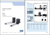
![[Linea D20 Fce]](https://img.yumpu.com/31507469/1/184x260/linea-d20-fce.jpg?quality=85)
![[Linea Micro XL]⢠⢠⢠- Electro Mechanical Systems Ltd.](https://img.yumpu.com/30934513/1/184x260/linea-micro-xla-a-a-electro-mechanical-systems-ltd.jpg?quality=85)