Create successful ePaper yourself
Turn your PDF publications into a flip-book with our unique Google optimized e-Paper software.
Product discription4 – 5MANETCONCEPT6 – 37MANETCOMPACT Sets38 – 49MANETAMBIENT50 – 65Installation tools/Accessories66 – 70
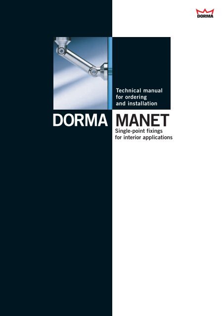
DORMA MANETGlass design systemMANET CONCEPTMANET COMPACT SetsToday’s approach to officedesign tends to be generouslyappointed, open-plan layouts.One of the basic underlyingprinciples in this regard isthat, in order to be effectivein business, you need a clearview of everything that ishappening.Consequently, flexible glasspartitions and doors are becomingthe preferred solutionfor internal spatial division.Thanks to the flexible modularityof the system, DORMAMANET offers architects andspecifiers a free hand increative almost bespokedesign with space, visionand light as a foundation.The basic component is thesingle-point fixing which iscountersunk into the glassand provides for a perfectlyflush finish in all applications.In addition to the countersunkversion, however, thesystem now also offers a newalternative, i.e. whereby thesingle-point fixing is clampedto the glass surface.When using these mountingelements, glazing systems of8 mm thickness as well asthe usual 10 and 12 mmthicknesses are available asstandard applications forsliding doors. Other glassthicknesses may also beavailable, and the installationof timber doors is likewisepossible. Design modificationsenable the freecombination of various rollercarrier and track rail types.Further details can be foundin the relevant introductorypages.Adjustable angle connectorsprovide for reliable attachmentto existing structuralcomponents or glass-to-glasscombinations, with integratedpivoting and sliding doorelements complimenting thesystem.Just as visually effective arethe MANET COMPACT standardisedsets from theDORMA MANET family.These facilitate single, fastplanning of the more popularsystem types with 8, 10or 12 mm glass for doorsand 10 and 12 mm glass foroverpanels and sidelights.The MANET COMPACT slidingdoor sets will be deliveredwith roller carrier inCLASSIC design.Optional accessories areavailable for increaseddesign variety within theindividual sets.The system componentscome with numerous adjustmentpossibilities in order toensure problem-free installationof the sliding, doubleaction or single action doors.Wall abutment profiles/connectors (for attachingthe overpanel and sidelightscreens to the existingstructure) may need to beprovided.4 10/07
MANET AMBIENTThe remarkableMANET AMBIENT range ofhardware breathes new lifeinto furniture creations.Sliding, pivoting, retention– this system transforms thefunctional into the stylish,affording the designeralmost unlimited scope forcreativity. Exacting in termsof its <strong>concept</strong> andengineering excellence, thishardware system is quiteunique in a number ofways - not least because thestainless steel fittings arenot concealed, servinginstead to accentuate exceptionalfurniture design.The MANET AMBIENTsystem approach is alsoreflected in the minimalnumber of basic componentsincorporated in theoverall range.At the heart of the systemis the rod - the connectingelement that also functionsas a support, track rail orpivot. Shelf supports andsingle-point fixings(flush-mounted in the glass)are further components inthis kit system with itsunique fitting methods,application range andmodularity.MANET AMBIENT is theideal aesthetic partner notonly to glass surfaces butalso to fine wood carcassfurniture - in offices, foyers,kitchens, living rooms andbedrooms. Hardly surprising,then, that this industrial-qualityproduct rangeis encountered not only inthe project hardware spherebut also, increasingly, inprivate homes as well.SlidingPivotingRetentionAll the elements includingthe pull handles are availablein an elegant stainless steelfinish (AISI 303).In applications involvingcorrosive atmospheres, manyfittings are also available instainless steel AISI 316L.Awarded with the design prizered dot 2002Needless to say, all DORMAsystems are protected byproprietary rights worldwide.We will be glad to provide youwith information concerningrelevant patents, e.g.PCT/EP03/04299,PCT/EP01/04255 etc. onapplication.11/06 5
DORMAMANET CONCEPT
MANETCONCEPTContentSingle-point fixing 8Connection system 10Pivoting door system 14Sliding door system 22Pull handles/door knobs 34
MANET CONCEPTSingle-point fixingSingle-point fixing series S32/35The basic component withinthe MANET system is thesingle-point fixing. Ratherthan cylindrical bore in theglass, this has a taperedcountersunk bore for a perfectseated fit to the glass. Thesegive a flush finish of thesingle-point fixing in all applications.The three-dimensional adjustabilityincorporated withinthe fitting ensures ideal compensationfor structural anddrilling tolerances.Constraint-free transmissionof all the forces acting on theglass to the substructure isalso ensured.1Threaded rod M8 withsmall head (eg DIN 6912).Length and type to suitWallplug on site towallplug.suit wall construction.3-dimensionaladjustment654Aperture forpost-installationAdjustment screwadjustment of screwallows offset fromwall to be altereddepending on typeof fitting.Post-installation adjustment2 3 of ± 2 mm horizontally andvertically by rotatingthe oblong hole.Components1 Clip-on cover2 Pin internal thread3 Conical sleeve4 Gasket5 Fixing6 Adjustment screwInstallation and adjustmentTransfer the drillingpoints from the installationdrawing to the wall.Drill anchor holes for wallplugs.Undo adjustment fastenerand secure to the wall.Only lightly tighten fastenerso that it can still bemoved.Mount the fixing andwasher and fit the glass.Undo the adjustmentfastener and then secure infinal position.Align single-point fixingsand secure with grub screw.Fit tapered nut and clampingring and tighten withspecial wrench (tighteningtorque 15 Nm).Clip on covers.8 11/06
Type and ordering informationØ 32Ø 35Ø 32Ø 35Ø 32Ø 35Ø 32Ø 358.5-11.511.5-14.514.5-22GlassthicknessGlassthicknessGlassthicknessGlassthickness6adjustableadjustableadjustablenotadjustableSingle-point fixing,Glass/WallGlass/Wall offsetadjustable 8.5 - 11.5 mmSingle-point fixing,Glass/WallGlass/Wall offsetadjustable 11.5 - 14.5 mmSingle-point fixing,Glass/WallGlass/Wall offsetadjustable 14.5 - 22 mmSingle-point fixing,Glass/WallGlass/Wall offset 6 mmnot adjustableComplete fittingComplete fittingComplete fittingComplete fittingGlass thickness 10 mm:Art. No. 8.29.200.700.99Glass thickness 10 mm:Art. No. 8.29.201.700.99Glass thickness 10 mm:Art. No. 8.29.202.700.99Glass thickness 10 mm:Art. No. 8.29.205.700.99Glass thickness 12 mm:Art. No. 8.29.210.700.99Glass thickness 12 mm:Art. No. 8.29.211.700.99Glass thickness 12 mm:Art. No. 8.29.212.700.99Glass thickness 12 mm:Art. No. 8.29.215.700.99Glass thickness 13.5 mm:Art. No. 8.29.240.700.99Glass thickness 13.5 mm:Art. No. 8.29.241.700.99Glass thickness 13.5 mm:Art. No. 8.29.242.700.99Glass thickness 13.5 mm:Art. No. 8.29.243.700.99Glass thickness 15 mm:Art. No. 8.29.244.700.99Glass thickness 15 mm:Art. No. 8.29.245.700.99Glass thickness 15 mm:Art. No. 8.29.246.700.99Glass thickness 15 mm:Art. No. 8.29.247.700.99Glass thickness 17.5 mm:Art. No. 8.29.248.700.99Glass thickness 17.5 mm:Art. No. 8.29.249.700.99Glass thickness 17.5 mm:Art. No. 8.29.250.700.99Glass thickness 17.5 mm:Art. No. 8.29.251.700.9911/06 9
MANET CONCEPTConnection systemConnection systemThe system approach is verymuch in evidence in the caseof the interconnecting components.Elements such asclamping and angle connectorsof various designs andalso interconnecting fastenersof various lengths can becombined in order to attachglass of different thicknessesat any required angle to thefloor, to ceilings, to walls andto plinth supports.Single-point fixings flushwith the glass are also usedfor this interconnection andglass-to-glass system.Tolerances are compensatedby sloted holes in the interconnectingfasteners.1 23 4Ordering information1Pivoting glass clampGlass thickness 8-12 mmArt. No. 8.29.160.700.99Glass thickn. 13.5-17.5 mmArt. No. 8.29.162.700.99Glass thickn.17.5-21.5 mmArt. No. 8.29.163.700.992Pivoting wall fixingArt. No. 8.21.141.700.993ColumnCeiling/floor fixingArt. No. 8.21.146.700.994Clamping connectorGlass thickness 8 - 12 mmArt. No. 8.29.149.700.99552.5 mm82 mm5Connecting rodLength 52.5 mmArt. No. 8.21.301.002.4060 mm103 mmLength 60 mmArt. No. 8.21.301.004.40Length 82 mmArt. No. 8.21.301.003.40Length 103 mmArt. No. 8.21.301.005.4010 11/06
Connection systemA90°-180°Glass/GlassConnector for double panelCB90°-180°Glass/WallOrdering informationAComplete fitting glass/glass8 - 12 mm glass thicknessWith connecting rod52.5 mmArt. No. 8.29.120.700.99AGlass/Glassø 36ø 32ø 20With connecting rod60 mmArt. No. 8.29.122.700.99With connecting rod82 mmArt. No. 8.29.125.700.99Connecting rod52.5 / 60 / 82 / 103 mm28Glass thicknessWith connecting rod103 mmArt. No. 8.29.130.700.99Glass thicknessBCComponents and assemblyof the glass fixing1 28Connecting rodsee page 10Connecting rod52.5 / 60 / 82 mmGlass3 4Components and assemblyof the wall fixingGlass/Wall120adjustable viaoblong holeGlass395grub screw10Threaded rod M8 withsmall head(e.g. DIN 6912).Length and type to suitwallplug.ø 2076112-dimensionaladjustment32.5Glass thickness8ø 32adjustable viaoblong holeø 36WallConnectingrodsee page 10Wallplug on site to suitwall construction.BComplete fittingglass/wall8-12 mm glass thicknessWith connecting rod52.5 mmArt. No. 8.29.139.700.99With connecting rod60 mmArt. No. 8.29.140.700.99With connecting rod82 mmArt. No. 8.29.142.700.99CComplete fittingConnectorfor glass thickness8-12 mmAISI 303Art. No. 8.29.148.700.99AISI 316LArt. No. 8.29.368.700.99Components1 Clip-on cover2 Connecting bolt3 Conical collar4 Conical sleeve5 Gasket6 Pivoting clamp7 Connecting bolt8 Connecting rodto suit length9 Connecting bolt10 Pivoting clamp11 Fixing plate11/06 11
MANET CONCEPTConnection systemConnection systemOrdering informationwith clampingdiscAClamping connectorComplete fittingGlass thickness 8 - 12 mmArt. No. 8.29.149.700.99ABCSingle-pointcountersunkBCorner connector 90°Glass/ceiling, Glass/floorconnectionAComponents/InstallationConnecting rodor steel cable1 2ø 2028 28ø 36Complete fittingGlass thickness 8 - 12 mm(only supporting function)Art. No. 8.29.145.700.99CCeiling fixing(bearing function)Complete fittingGlass thickness 8 - 12 mmcountersunkArt. No. 8.29.337.700.99clamping discArt. No. 8.29.338.700.994 5Components3 4adjustable viaoblong hole1Connecting boltBHanging glass fromthe ceiling is permissiblewhere there isother support for theglass sheet.2-dimensionaladjustmentThreaded rodM8 with small head(eg DIN 6912).Length and type tosuit wallplug.Grub screwWallplug onsite to suitwall construction.672Pivoting clamp3Connecting bolt4Gasket5Pivoting clamp6Fixing plate7ColumnCClip-on coverHeight adjustmentvia grub screwSingle-point fixingcountersunkSingle-point fixingclamping discFixing with cheeseheadscrewDIN 7984 M10 x...,oroval-head wood screwDIN 7996 M8 x...depending on ceilingfixing requirements andwallplug type(by others)12 11/06
Glass preparation for single-point fixings and corner connectionsFor ESG and VSG out of ESG.Recommended centres forfixed glazing elementmax. 800 ±0.3max. 800 ±0.3±0.3Countersunk borefor countersunk single-pointfixings90°ø 32 +0.23 -0.2ø 26Cylindrical borefor clamping discsingle-point fixingsø 26 +0.2Glass thicknessGlass thicknessDimension A3Dimension A390°Dimension B28AngleWallDimension BConnecting rodDimension AConnecting rod28332.5Plan viewCorner connectorsGlass/Glass 90° - 180°AngleConnecting rodDimension B28Corner connectorsGlass/Wall 90 - 180°Dimensions in mmCorner connectorsGlass/GlassAngle90°95°100°105°110°115°120°125°130°135°180°A/B75706662595552494744Glass/WallAngle90°Length ofConnecting rod52.5 60 82 103Dimensions for 10 mm glassthickness (consider variantsfor other glass thicknesses).A/B80757167636056545148A/B96908581777369666360A/B50Length ofConnecting rod52.5 60 82Dimensions for 10 mm glassthickness (consider variantsfor other glass thicknesses).A/B A/B A/B67/65 72/70 87.5/86Clamping connector150Ensure compliancewith minimum glass/boreclearances as per glassmanufacturer recommendationsCylindrical bore28Ø1532860Corner connector glass/ceilingCorner connector glass/floorCeiling fixing (bearing)Ceiling 2841.57275727565567Ceiling283KSFloorGlass thicknessVerticallyadjustment± 2.5Glass preparationwith a tolerance ofmax. ± 0.3 mmis recommended.11/06 13
MANET CONCEPTPivoting door systemPivoting door systemMANET pivoting doors can beinstalled in both glass partitionsand masonry openings.They come as both single anddouble-action swing doors witha maximum weight of 100 kgand a maximum leaf width of1200 mm.All the single-point fixings aredesigned for clip-on covers foreasier installation. Other componentsinclude the bottompivot bearing, top pivot fittingswith bearing spigot or eccentricbushing and also overpanel/sidelightconnectors.As a result, there are almostunlimited possibilities for integratingframeless swing doorsboth in masonry openings –with or without overpanels andsidelights – and in glass partitionconstructions retained bysingle-point fixings.The pivoting door system hasundergone a number of improvements.Whether with a fulllengthpivot rod or a pair ofshorter pivot rods, the topbearing socket is now locatedin the fitting on the door leaf.This means that connection tothe ceiling, lintel or transomcan now be provided in theform of the standard PT25 toppivot spigot from the DORMArange.The door assemblies can beequipped with floor springssuch as the DORMA BTS 75V,and corner locks are naturallyalso available.Pivot bearing withfull-length pivot rodPivot bearing withpivot rod pairshort typePivot bearing withpivot rod pairshort type withintermediate tube14 03/07
Components for pivoting door systemAGlassthicknessOrdering information11518.5A Overpanel/sidelight connectorcomplete fittingfor 10/12 mm glassArt. No. 8.29.330.700.99AISI 316LArt. No. 8.29.362.700.99B Pivot fittingfor overpanelArt. No. 8.21.310.700.99AISI 316LArt. No. 8.21.350.700.99B18.5C Pivot rod,drilled, fixed lengthArt. No. 8.21.300.700.99AISI 316LArt. No. 8.21.340.700.9976Single-point fixing,countersunk, fixed 1for 10/12 mm glassArt. No. 8.29.460.700.99AISI 316LArt. No. 8.29.461.700.99for 13.5 - 15.5 mm glassArt. No. 8.29.450.700.99CD2221intermediate tube838918.5ø 25Glassthicknessø 32 ø 32Single-point fixing,countersunk, centring2for 10/12 mm glassArt. No. 8.29.462.700.99AISI 316LArt. No. 8.29.463.700.99for 13.5 - 15.5 mm glassArt. No. 8.29.455.700.99Pivot rod set,short typetop/bottom,incl. 4 single-point fixingsArt. No. 8.29.302.700.99AISI 316LArt. No. 8.29.342.700.99ditto for intermediate tubeArt. No. 8.29.303.700.99AISI 316LArt. No. 8.29.343.700.99Intermediate tubefixed length up to 2 mArt. No. 8.21.305.700.99AISI 316LArt. No. 8.21.345.700.99Stock length 1.923 mmArt. No. 8.21.304.700.99AISI 316LArt. No. 8.21.344.700.997618.5D Pivot bearing forDORMA BTS/floor pivotArt. No. 8.21.311.700.99AISI 316LArt. No. 8.21.351.700.9907/07 15
MANET CONCEPTPivoting door systemComponents for pivoting door systemOrdering information76Pivot bearing for wet roomsArt. No. 8.21.540.700.9918.5159232.5Floor pivotArt. No. 8.01.106.700.9911518.5GlassthicknessPivot bearing locationfor overpanelfor 8 - 12 mm glass,Art. No. 8.29.333.700.99AISI 316LArt. No. 8.29.353.700.99115ø2518.5Glassthickness60Pivot bearing fittingfor overpanel withcylindrical bore for rodfor 8 - 12 mm glass,Art. No. 8.29.354.700.99105463Pivot bearing for RTSArt. No. 8.21.314.700.9976Glassthickness40M8PT 25 top pivotfor ceiling connection,15 mm Ø, with plugArt. No. 8.01.115.000.9918.576Pivot bearing forinstallation to ceilingadjustablefor 8 - 12 mm glass,AISI 316LArt. No. 8.21.318.700.9916 11/06
Components for pivoting door systemACEFDB7373.573.573.573.5733370 70 7033 370 70703A12018.5Glassthickness115BOrdering informationOverpanel/sidelightconnector for glass fixing90° offset,with pivot bearing location,complete fittingfor 10 and 12 mm glass,A right handArt. No. 8.29.331.700.99B left handArt. No. 8.29.332.700.99C12018.5DOverpanel/sidelightconnector for wall fixing90° offset,with pivot bearing location,complete fittingfor 10 and 12 mm glass,C right handArt. No. 8.29.328.700.99D left handArt. No. 8.29.329.700.99E120FOverpanel/sidelightconnector for wall fixing90° offset,complete fittingfor 10 and 12 mm glass,E right handArt. No. 8.29.326.700.99F left handArt. No. 8.29.327.700.9911/06 17
MANET CONCEPTPivoting door systemComponents for pivoting door system39Ordering informationCeiling40Stop for pivoting doorwith ceiling mountingArt. No. 8.21.334.700.995307340Stop at overpanel(inside/outside)for 10 and 12 mm glass,Art. No. 8.29.335.700.9930120Overpanel-sidelightconnectionfor 10 and 12 mm glass,Art. No. 8.29.320.700.99AISI 316LArt. No. 8.29.360.700.99340120Overpanel-sidelightconnectionwith stop insidefor 10 and 12 mm glass,Art. No. 8.29.322.700.99340GlassthicknessGlassthicknessGlassthicknessGlassthickness12040Overpanel-sidelightconnectionwith stop outsidefor 10 mm glass,Art. No. 8.29.324.700.99for 12 mm glass,Art. No. 8.29.325.700.99318 11/06
Components for pivoting door systemOrdering informationWall24.5GlassStop for pivoting doorfloor mountingArt. No. 8.29.950.700.9940FloorWall31ø 20GlassStop for pivoting doorwall mounting, shortArt. No. 8.29.951.700.99Wall94Glassø 20Stop for pivoting doorwall mounting, longArt. No. 8.29.952.700.99ø557365113Corner lockfor 8 - 12 mm glass,Art. No. 8.21.448.700.997FloorGlassthickness21ø5512765Corner lockwith profile cylinder rose oninside for 8 - 12 mm glass,Art. No. 8.21.449.700.99Profile cylinderfor corner lockArt. No. 8.14.206.000.9965FloorAB3ø 25ø 4028.5FloorA Eccentric bushingArt. No. 8.05.194.000.99B Bushing, plasticsArt. No. 8.00.110.133.32ø 15.5C Strike plateArt. No. 8.05.190.000.99C943211/06 19
MANET CONCEPTPivoting door systemComponents for pivoting door systemThe gap and distancedimensions recommended byDORMA are indicated in theadjacent table.Glass thicknessmm10/1213.5-15.5ConnectionSidelightWallSidelightWallXGap58811Y6562Glass thicknessCountersunkholes90°ø 32 +0.2ø 263-0.2Detail ADetail Ato wallDetail Ato sidelight11311333XXYYDetail Bto wallDetail Bto glass wallDetail Cto wallDetail B3703 370 70Detail C160504011340113 120340120XYXY20 11/06
Glass preparation for pivoting door systemDetail D5067Detail D3Detail EYXYGlassBTSDetail BDetail EDetail Ewith stop4040113Overall length of pivot rod = Door height - 54 mm2489113 X1 ± 0.3X2 ± 0.3X3 ± 0.318.5750403120FFLDetail E3 33312012067 50367 50311/06 21
MANET CONCEPTSliding door systemSliding door systemThe MANET sliding doorsystem is ideal as an elegantaddition complementinghigh-style interior <strong>concept</strong>s.Its main components take theform of a solid track rail andthe roller carrier. Whether youprefer the TREND or CLASSICversions, both can be combinedwith the solid track or atubular track by simply replacingthe anti-jump device.The range includes both glassflushand proud single-pointfixings. The sliding doorsystem allows plenty of scopefor individual ideas.In addition to the standardversions incorporated intoughened glass partitionsor face-fixed on masonryopenings, this hardwaresystem can also be used toconstruct curved sliding doors,biparting sliding doors andparallel sliding doors.The fittings are designed fora door weight of max. 120 kg.Mechanical stops that can bepositioned on the track railensure that the door traveldistance is effectively limited.Roller carrier TRENDRoller carrier CLASSICRoller carrier TRENDRoller carrier CLASSICDifferent anti-jumpdevices for solid andtubular track railsGlass connection with drilled solid track railsGlass connection with clamp fixing and tubes22 07/06
Roller carrierOrdering informationRoller carrier TRENDRoller carrier TRENDincl. anti-jump device(both variants)only lug with rollerArt. No. 8.29.414.700.9955208555555Roller carrier CLASSIC205Roller carrier CLASSICincl. anti-jump device(both variants)only lug with rollerArt. No. 8.29.400.700.99AISI 316LArt. No. 8.29.401.700.992 piece single-point fixingfor roller carrier:countersunk 8 -12mm glassArt. No. 8.29.430.700.99AISI 316LArt. No. 8.29.431.700.99clamping disc 8-12mm glassArt. No. 8.29.432.700.99AISI 316LArt. No. 8.29.433.700.99countersunkfor 13.5 - 17.5 mm glassArt. No. 8.29.435.700.99countersunk f. 19 mm glassArt. No. 8.29.437.700.9907/07 23
MANET CONCEPTSliding door systemRoller carrier single point fixings for timber doorsInsertsolid track railZGlass thicknessInsertsliding track tubeZGlass thicknessOrdering information6015376015X372 pieces single point fixingfor roller carrier:TREND / CLASSICcountersunkor clamping discsee tableFor solid track rail555535 2835 28XHeight adjustment-2.5Height adjustment-2.5Xmm20 - 30Zmm18.5max.doorweightkg120Single-point fixing (2 pcs)for roller carrierArt. No.countersunk clamping discFlange fixingtrack to wallsee page 27Art. No.21.346Single-point fixing fixedfor track to glass10/12 mm, see page 26Art. No.countersunk clamping disc29.460 29.465Single-point fixing centringfor track to glass10/12 mm, see page 26Art. No.countersunk clamping disc29.462 29.46729.510 29.52035 - 403510021.41229.530 29.53529.531 29.536For sliding track tubeXmm20 - 30Zmm18.5max.doorweightkg120Single-point fixing (2 pcs)for roller carrierArt. No.countersunk clamping disc29.510 29.520Clamp fixing fortrack to wallsee page 29Art. No.21.153Clamp fixing fortrack to glasssee page 29Art. No.countersunk clamping disc29.171 29.17235 - 403510021.15729.518 29.51924 11/06
Solid track rail Supply and installationTrack supply and installationThe track rail for the slidingdoor is pre-fabricated accordingto the customer’s drawingand supplied together with theglass or wall brackets orderedfor the application concerned.Required dimensions for the track productionFixing screws for wallinstallation by othersOf decisive importance for prefabricationand fixing to glasspartitions is that the mountingpoints coincide with the holesdrilled in the glass. The lengthwisetolerances should not begreater than +/- 0.3 mm.Caution! Ensure that the stops/single-point fixings arepositioned at locations appropriate to the width of thedoor.Wall/single-pointfixing clearance whenusing the wallconnector(depends on stopperposition).For rail support intervals onthe glass wall or masonry,see fixing point intervalrecommendations per thetable.GW= Fixing point to glass= Fixing point to wallK = ConnectionWK = Angle-connectionGG W Wsee table 503100 see tableTrack lengthGGG K*G Gsee tablemax. 5000 with connector100 100see tablemax. 5000 with connectormin. 80* Note!Ensure that track joints and glass joints do not coincide337.5G18.5G G Gmin. 8037.5WKsee table see table see tablemax. 5000 with angle-connector18.5Doorheightin mmRecommended distance of the track fixing pointsDoor width in mm700 800 900 1000 1100 1200 1300 1400Glass thickn. mm Glass thickn. mm Glass thickn. mm Glass thickn. mm Glass thickn. mm Glass thickn. mm Glass thickn. mm Glass thickn. mm8 10 12 8 10 12 8 10 12 8 10 12 8 10 12 8 10 12 8 10 12 8 10 121900200021002200230024002500770750730710690680660710700680660640630610670650640620610590580770 720750 700730 680710 660700 650680 630670 620670660640620610590580770750730710700680670710690680660650630620670650640620610590580760740730710690680660710690670660640630620670650630620600590580760740720700690670660700680670650640620610660640630610600590580750730710700680670650700680660650630620610650640620610600580570740720710690680660650690670660640630610600650630620600590580570730720700680670660640680660650630620610600640630610600580--11/06 25
MANET CONCEPTSliding door systemComponents for sliding door system Solid track rail and accessoriesOrdering informationTrack, drilledSolid track railThe track rail isprefabricated percustomer specifications/drawingwith all the necessarydrill holesalready provided.up to 6 m*ø 25*max. single length 5 mby couplingfor fixing on glassup to 6 mArt. No. 8.21.405.700.99AISI 316LArt. No. 8.21.456.700.99for fixing on wallup to 6 mArt. No. 8.21.406.700.99AISI 316LArt. No. 8.21.457.700.99Connection 180°Connectorsincl. frontal preparation intracks,for tracks 180°Art. No. 8.21.404.700.99Threaded rodM5 x6Angleconnection90 - 180°37.537.5offsetfor tracks 90 - 180°Art. No. 8.21.442.700.99A for *X = 20 - 30 mmSingle-point fixing,countersunk, fixedfor 10 and12 mm glassB for *X = 35 - 40 mmSingle-point fixing,countersunk, fixedfor 10 and12 mm glassSingle point fixing for fixing thetrack to glassArt. No. 8.29.460.700.99AISI 316LArt. No. 8.29.461.700.99Art. No. 8.29.530.700.99AGlass thicknessfor 13.5 - 15.5 mm glassArt. No. 8.29.450.700.99for 17.5 mm glassArt. No. 8.29.451.700.99ø 25clamping disc, fixedfor 10/12 mm GlasArt. No. 8.29.465.700.99countersunk, centringfor 10 and 12 mm glassclamping disc, fixedfor 10/12 mm GlasArt. No. 8.29.535.700.99countersunk, centringfor 10 and 12 mm glassB18.5Glass thicknessArt. No. 8.29.462.700.99AISI 316LArt. No. 8.29.463.700.99for 13.5 - 15.5 mm glassArt. No. 8.29.455.700.99for 17.5 mm glassArt. No. 8.29.456.700.99Art. No. 8.29.531.700.99ø 25clamping disc, centringfor 10/12 mm glassclamping disc, centringfor 10/12 mm glass35Art. No. 8.29.467.700.99AISI 316LArt. No. 8.29.468.700.99Art. No. 8.29.536.700.99Recommended distance of the fixing points see page 25 *for X see page 2426 11/06
Components for sliding door system Solid track rail and accessoriesOrdering informationFlange for fixing the trackto wallFlange for fixing the trackto wall,adjustableFlange for fixing a double track60 ø 25ø 2518.52-dimensional adjustmentvia oblong hole18.535Adjustment+ 5 mm10/12ø 55Note: Min. distanceglass to wall 32 mmø 20Flange for fixing the trackto wallArt. No. 8.21.346.700.99AISI 316LArt. No. 8.21.347.700.99Flange for fixing the trackto wall, adjustableArt. No. 8.21.412.700.99Fixing for double trackArt. No. 8.21.170.700.99ø 65ø 25110Ceiling retainer for trackcarrying functionArt. No. 8.21.315.700.9929ø 25Recommended distance of the fixing points see page 2511/06 27
MANET CONCEPTSliding door systemComponents for sliding door system Tube and accessoriesRecommended distance of thetrack fixing pointssee tableDoorheightin mmDoor width in mm700 800 900 1000 1100 1200 1300 1400Glass thickn. mm Glass thickn. mm Glass thickn. mm Glass thickn. mm Glass thickn. mm Glass thickn. mm Glass thickn. mm Glass thickn. mm8 10 12 8 10 12 8 10 12 8 10 12 8 10 12 8 10 12 8 10 12 8 10 121900200021002200230024002500350350350350350350350350350350350350350350350350350350350350350400400400400400400400400400400400400400400400400400400400400400450450450450450450450450450450450450450450450450450450450450450500500500500500500500500500500500500500490500500500490480470460550550550550550530520550540530520510500490530510500490480470460600580570550540530520550540530510500490480520510500480470460450590570560550540530520550530520510500490480510500490480470460450580570560540530520510540530520500490480470510500490470460--Ordering information3 m/6mø 25Sliding track tubeincl. end plugsstock length 3 mArt. No. 8.21.527.700.99AISI 316LArt. No. 8.21.530.700.99Fixed length up to 6 mArt. No. 8.21.436.700.99AISI 316LArt. No. 8.21.532.700.99Curve lengthr =min. 600 mmSliding track tubebent, incl. end plugsmax. curve length 2.6 mArt. No. 8.21.409.700.99max. curve length 5.6 mArt. No. 8.21.413.700.99ø 214040Angle connectionfor sliding track tubeArt. No. 8.29.506.700.99ø 2140Thread insertfor sliding track tubeArt. No. 8.29.505.700.9928 07/06
Components for sliding door system Tube and accessoriesø 25ø 25Glass thickness18.5Glass thickness35Ordering informationClamp fixingfor sliding track tube toglass, single-point fixingcountersunkfor 10, 12 and 13.5 mm glassArt. No. 8.29.171.700.99AISI 316LArt. No. 8.29.181.700.99single-point fixing, clamping discfor 10, 12 and 13.5 mm glassArt. No. 8.29.172.700.99AISI 316LArt. No. 8.29.182.700.9916 mm extendedsingle-point fixing, countersunkfor 10, 12 and 13.5 mm glassArt. No. 8.29.518.700.99AISI 316LArt. No. 8.29.183.700.99single-point fixing, clamping discfor 10, 12 and 13.5 mm glassArt. No. 8.29.174.700.99AISI 316LArt. No. 8.29.184.700.99ø 2518.5Clamp fixingfor sliding track tube to wallArt. No. 8.21.153.700.99AISI 316LArt. No. 8.21.163.700.99ø 2535Clamp fixingfor sliding track tube to wall16 mm extendedArt. No. 8.21.157.700.99ø 2548Clamp fixingto fix the sliding track tubefor double panelled slidingdoorsArt. No. 8.21.154.700.99ø 65ø 25110Ceiling retainerfor sliding track tube,carrying functionArt. No. 8.21.316.700.9926ø 2511/06 29
MANET CONCEPTSliding door systemGlass preparation for sliding door systemSliding door to wallDetail ADetail BWallSliding doorWallSliding door with sidelight and overpanelOverpanelDetail CDetail DWallSliding doorSidelightSliding door with two sidelights and overpanelOverpanelDetail EDetail DSidelightSliding doorSidelight30 11/06
Glass preparation for sliding door systemDetail ADetail BSliding door withsolid track rail18.55027.527.5Detail DSliding door with tube andclamp fixing27.5556035143 1434040Detail C318.550 5050603527.5143143glass edge protectionon site4055Detail E501003Dimensional data should be regardedexclusively as recommended values.Please remember when designingyour system that the positions of thestops and point fixings must notvertically coincide.Countersunkbore for countersunksinglepointfixings3 - 0.2Cylindrical borefor clampingdisc singlepointfixings40143For spacing/interval recommendationswhen drilling the track holes,and for requisite dimensions forfixing the track rail,please refer to the table entitled“Recommended distance of the trackfixing points”.ø 26ø 32 +0.290°ø 26Glass thicknessGlass thickness11/06 31
MANET CONCEPTSliding door systemComponents for sliding door systemleft handright handOrdering informationDoor stopleft handArt. No. 8.29.425.700.99AISI 316LArt. No. 8.29.427.700.99right handArt. No. 8.29.426.700.99AISI 316LArt. No. 8.29.428.700.99ø 3556ø 25Wall fixing fortube /solid track railArt. No. 8.29.445.700.99AISI 316LArt. No. 8.29.446.700.992070stop is usable left hand andright handRoller to glassfor 8 - 12 mm glass,countersunkArt. No. 8.29.494.700.99clamping discArt. No. 8.29.495.700.99Door stopfor roller to glassArt. No. 8.29.493.700.99Anti-jump devicefor roller to glassfor 8 - 12 mm glass,countersunkArt. No. 8.29.497.700.99clamping discArt. No. 8.29.498.700.9950356Door steady,to prevent glass edges ofdouble sliding doorsbumping into each otherArt. No. 8.29.420.700.9932 02/08
Components for sliding door systemOrdering information15.5for 8 mm glass13.5for 10 mm glass11.5for 12 mm glassAluminium brush profilesimilar satin stainless steelfor 8 mm glassstock length 3 mArt. No. 8.07.402.113.99fixed length up to 6 mArt. No. 8.07.403.113.99for 10/12 mm glassstock length 3 mArt. No. 8.07.400.113.99fixed length up to 6 mArt. No. 8.07.401.113.9937.5ø 38ø 4875Sliding door lock withratchet bracefor 8/10/12 mm glassArt. No. 8.21.446.700.99AISI 316L13.515152430Guide rail with brush sealsapplicable for8/10/12 mm glassaluminium mill finishedfixed length up to 6 mArt. No. 8.21.431.100.99stock length 3 mArt. No. 8.21.432.100.993050 723Floor guideclamping disc,applicable for8/10/12/13.5 mm glassArt. No. 8.07.326.000.9911/06 33
MANET CONCEPTPull handle/knob systemPull handles and door knobsThe pull handle/knob systemis designed for glass of 8, 10and 12 mm thickness.The pull handles can be fixedto both sliding and pivoting(swing) doors on one faceusing the appropriate connectorsor on both faces bythrough-bolting (back-to-backarrangement). The singlepointfixings and throughbolts are included as standardequipment in the scope ofsupply.The pull handles can be fittedhorizontally, vertically or in ahandrail arrangement.Ordering informationPull handles with singlepointfixings, countersunkfor 8/10/12 mm glassPull handle 350 mmwith 2 fixingsArt. No. 8.29.268.700.99AISI 316LArt. No. 8.29.269.700.99Pull handle 720 mmwith 2 fixingsArt. No. 8.29.271.700.99AISI 316LArt. No. 8.29.272.700.99Complete withsingle-point fixings12401760Pull handle 1240 mmwith 3 fixingsArt. No. 8.29.274.700.99AISI 316LArt. No. 8.29.275.700.99Pull handle 1760 mmwith 4 fixingsArt. No. 8.29.277.700.99AISI 316LArt. No. 8.29.278.700.99150350520720520520Pull handles with clampingdisc single-point fixingsfor 8/10/12 mm glassSingle-point fixingcountersunkSingle-pointfixingclamping discPull handle 350 mmwith 2 fixingsArt. No. 8.21.240.700.99AISI 316LArt. No. 8.21.280.700.99GlassthicknessPull handle 720 mmwith 2 fixingsArt. No. 8.21.241.700.99AISI 316LArt. No. 8.21.281.700.99ø 32ø 1645.5ø 25Pull handle 1240 mmwith 3 fixingsArt. No. 8.21.242.700.99AISI 316LArt. No. 8.21.282.700.99Pull handle 1760 mmwith 4 fixingsArt. No. 8.21.243.700.99AISI 316LArt. No. 8.21.283.700.9934 11/06
Pull handles and door knobsOrdering informationComplete withconnecting boltPair of pull handlesincl. connecting boltfor 8/10/12 mm glass52072052012401760Pair of pull handles350 mm, with 2 fixingsArt. No. 8.21.267.700.99AISI 316LArt. No. 8.21.247.700.99Pair of pull handles720 mm, with 2 fixingsArt. No. 8.21.270.700.99AISI 316LArt. No. 8.21.250.700.99Glass thicknessPair of pull handles1240 mm, with 3 fixingsArt. No. 8.21.273.700.99AISI 316LArt. No. 8.21.253.700.99ø 25ø 1645 70ø 25Pair of pull handles1760 mm, with 4 fixingsArt. No. 8.21.276.700.99AISI 316LArt. No. 8.21.256.700.99Door knob one side fixingfür 8/10/12 mm Glassingle-pointfixingcountersunkø 32single-pointfixingclamping discGlass thickness51ø 25Door knob with single-pointfixing, countersunkArt. No. 8.21.422.700.99Door knob with clampingdisc single-point fixingsArt. No. 8.21.426.700.99GlassthicknessDoor knob back-to-backfor 8/10/12 mm glassArt. No. 8.21.423.700.99ø 2515035052051 5111/06 35
MANET CONCEPTPull handle/knob systemSpacing adjustment for pull handles and door knobsDistance washer2 mmDistance washer5 mmGlass doorsdoor thickn. 13.5 mm: without Distancewasherdoor thickn. 15 mm: with 1 Distance washerdoor thickn. 17.5 mm: with 2 Distance washerdoor thickn. 19 mm: with 3 Distance washerdoor thickn. 21.5 mm: with 4 Distance washerTimber doorsdoor thickn. 20 mm: without distance washerdoor thickn. 25 mm: with 1 distance washerdoor thickn. 30 mm: with 2 distance washerdoor thickn. 35 mm: with 3 distance washerdoor thickn. 40 mm: with 4 distance washerOrdering informationConversion set 1 forglass doors,pair of pull handles/knob back-to-backdoor thickn. 13.5–21.5 mmArt. No. 8.21.285.700.99Conversion set 2 fortimber doors,pair of pull handles/knob back-to-backdoor thickn. 20–40 mmArt. No. 8.21.286.700.99Glass doors/timber doorsdoor thickn. 15–21.5 mm: cylinder head screw M6x25door thickn. 25–30 mm: cylinder head screw M6x35door thickn. 35–40 mm: cylinder head screw M6x50Glass preparation pull handles and door knobsConversion set 3for glass/timber doors,pull handle/knob single-sided,single-point fixingcountersunk/clamping discdoor thickn. 15–40 mmArt. No. 8.21.287.700.99min. ca. 65Countersunk boreon pull handle and door knob,one side fixing3 - 0.2min. ca. 65ø 26ø 32 +0.2Glass thicknessø 22150 mm ±0.3520 mm ±0.31040 mm ±0.31560 mm ±0.390°Cylindrical boreon pair of pull handlesand door knobs,back-to-backat length of pull handles350 mmGlass thickness36 11/06
Recessed pull grip und ARCOS pull handleOrdering informationø 5020 3GlassthicknessCylindricalboreø 38GlassthicknessRecessed pull gripØ 50 mmfor 8/10/12 mm glassArt. No. 8.21.290.700.999 9ø 60Cylindricalboreø 50Recessed pull gripØ 60 mmfor 8/10/12 mm glassArt. No. 8.21.291.700.99Grub screw85~ 65ARCOS pair of pull handlefor 8/10/12 mm glassincl. connecting boltonly in AISI 316LBushingConnectingboltPull handle 350 mmwith 2 fixingsArt. No. 8.26.500.700.99Pull handle 750 mmwith 2 fixingsArt. No. 8.26.510.700.99GlassthicknessCylindrical boreø16ø16Glass thicknessGlass thickness350/750 mm drill hole centres398/824 mm80Glassthickness07/07 37
DORMAMANET COMPACT Sets
MANETCOMPACT SetsContentPivoting door 40Sliding door 44
MANET COMPACTSetsMANET COMPACT SetsThe aesthetic elegance of theMANET COMPACT <strong>concept</strong> isalso available in the form ofstandardised sets for simple,fast planning of the morepopular system types with 8,10 or 12 mm toughenedsafety glass (TSG).Optional accessories enablethe individual sets to besemi-customised.The system components offernumerous adjustment possibilitiesin order to ensure problem-freeinstallation ofwhichever door type – slidingor swing, single action ordouble action – is required.Wall abutment profiles mayneed to be provided (byothers) for fixing overpanelsand sidelights.Pivoting doorsSet 1page 41Construction 1 (1 set) Construction 2 (1 set) Construction 3 (1 set) Construction 4 (1 set)Construction 5 (2 sets) Construction 6 (2 sets) Construction 7 (2 sets) Construction 8 (2 sets)Pivoting doorsSet 2page 42Pivoting doorsSet 2 + 3page 42/43Construction 9 (1 set) Construction 12 (1 set) Construction 18 (2 sets)Pivoting doorsSet 3page 43Construction 21 (each 1 set)Construction 13 (1 set) Construction 15 (1 set) Construction 23 (2 sets)Sliding doorsSet 4/5/6page 44 - 49Set 4.1/4.2 Set 5.1/5.2 Set 6.1/6.240 11/06
S 8S 8Set 1Pivoting door MANET COMPACT without overpanel for 10 - 12 mm glassSet 1 consisting of:pivot rod pair top/bottom,short type,Ordering informationArt. No. 8.29.910.700.99including:4 Single-point fixings for pivot rods,1 Pivot fitting top,1 PT 25 pin, 15 mm Ø, with plug1 Pivot fitting bottomfor DORMA BTS/floor pivotSet 1with pivot rod pairshort typeOption:Set 1, but with additional intermediate tube for pivot rod pairin fixed lengthArt. No. 8.29.911.700.99Essential information:CeilingPanel height _________ mm– 577 mm= Length intermed. tube_________ mm3 Gap150 113Options for SET 165Pull handles Length 350 mmLength 720 mmLength 1240 mmLength 1760 mmArt. No. 8.29.268.700.99Art. No. 8.29.271.700.99Art. No. 8.29.274.700.99Art. No. 8.29.277.700.99Door weight80 kgDoor height2500 mmDoor width1200 mmPair of pull handles Length 350 mmLength 720 mmLength 1240 mmLength 1760 mmStopfor pivoting door with ceiling mountingCeiling fixing (bearing function)Corner lockCorner lockwith rose on one lock sideArt. No. 8.21.267.700.99Art. No. 8.21.270.700.99Art. No. 8.21.273.700.99Art. No. 8.21.276.700.99Art. No. 8.21.334.700.99Art. No. 8.29.337.700.99Art. No. 8.21.448.700.99Art. No. 8.21.449.700.99Gapto sidelight 5to wall 8Profile cylinder forcorner lock 8.21.448/449.700.99Eccentric bushing forcorner lock 8.21.448/449.700.99Art. No. 8.14.206.000.99Art. No. 8.05.194.700.997 Gap65150113DORMABTSFloor pivot bearingAssembling tool for MANET single-pointfixings5 pcs. clip-on cover f. single-point fixingsSample cases MANET COMPACTfor advice and presentationArt. No. 8.01.106.700.99Art. No. 8.21.134.000.99Art. No. 8.29.217.700.99Art. No. 8.21.994.700.99For the requisite glass preparationplease see pages 20/2107/07 41
MANET COMPACTSetsSet 2Pivoting door MANET COMPACT with overpanel for 10 - 12 mm glassOrdering informationSet 2 consisting of:pivot rod pair top/bottom,short type,Art. No. 8.29.912.700.99Set 2with pivot rod pairshort typeincluding:4 Single-point fixings for pivot rods,1 Pivot fitting top,1 Pivot bearing location for overpanel1 Pivot fitting bottomfor DORMA BTS/floor pivotOption:Set 2, but with additional intermediate tube for pivot rod pairin fixed lengthEssential information:OverpanelPanel height _______ mm– 577 mm= Length intermed. tube_______ mmArt. No. 8.29.913.700.993 Gap150 11365Options for SET 2Pull handles Length 350 mmLength 720 mmLength 1240 mmLength 1760 mmPair of pull handles Length 350 mmLength 720 mmLength 1240 mmLength 1760 mmArt. No. 8.29.268.700.99Art. No. 8.29.271.700.99Art. No. 8.29.274.700.99Art. No. 8.29.277.700.99Art. No. 8.21.267.700.99Art. No. 8.21.270.700.99Art. No. 8.21.273.700.99Art. No. 8.21.276.700.997 GapWallDoor weight80 kgDoor height2500 mmDoor width1200 mmGap towall 865150113DORMABTSFor the requisite glass preparationplease see pages 20/21Ceiling fixing (bearing function)Stop at overpanel, (inside/outside)for 10 and 12 mm glassCorner lock top/bottomCorner lock top/bottomwith rose on one locksideProfile cylinder forcorner lock 8.21.448/449.700.99Eccentric bushing forcorner lock 8.21.448/449.700.99Overpanel-sidel. conn. for 10/12 mm glassOverp.-sidel. conn. with stop inside for10 and 12 mm glassOverp.-sidel. conn. with stop outsidefor 10 mm glassfor 12 mm glassFloor pivotAssembling tool for MANET-single-point f.5 pcs. clip-on cover f. single-point fixingsSample cases MANET COMPACTfor advice and presentationArt. No. 8.29.337.700.99Art. No. 8.29.335.700.99Art. No. 8.21.448.700.99Art. No. 8.21.449.700.99Art. No. 8.14.206.000.99Art. No. 8.05.194.700.99Art. No. 8.29.320.700.99Art. No. 8.29.322.700.99Art. No. 8.29.324.700.99Art. No. 8.29.325.700.99Art. No. 8.01.106.700.99Art. No. 8.21.134.000.99Art. No. 8.29.217.700.99Art. No. 8.21.994.700.9942 07/07
Set 3Pivoting door MANET COMPACT with overpanel and sidelight for 10 - 12 mmglassOrdering informationSet 3with pivot rod pair,short type3 GapSet 3 consisting of:pivot rod pair top/bottom,short type,including:4 Single-point fixing for pivot rods,1 Pivot fitting top,1 Overpanel-sidelight connector withpivot bearing location,1 Pivot fitting bottomfor DORMA BTS/floor pivot bearingOption:Set 3, but with additional intermediate tube for pivot rod pairin fixed lengthEssential information:OverpanelPanel height ________ mm– 577 mm= Length intermed. tube_________ mmArt. No. 8.29.914.700.99Art. No. 8.29.915.700.993 Gap150 11365Options for SET 3Pull handles Length 350 mmLength 720 mmLength 1240 mmLength 1760 mmPair of pull handles Length 350 mmLength 720 mmLength 1240 mmLength 1760 mmArt. No. 8.29.268.700.99Art. No. 8.29.271.700.99Art. No. 8.29.274.700.99Art. No. 8.29.277.700.99Art. No. 8.21.267.700.99Art. No. 8.21.270.700.99Art. No. 8.21.273.700.99Art. No. 8.21.276.700.997 GapSidelightDoor weight80 kgDoor height2500 mmDoor width1200 mmGap towall 815011365DORMABTSFor the requisite glass preparationplease see pages 20/21Ceiling fixing (bearing function)Stop at overpanel, (inside/outside)for 10 and 12 mm glassCorner lockCorner lockwith rose on one locksideProfile cylinder forcorner lock 8.21.448/449.700.99Eccentric bushing forcorner lock 8.21.448/449.700.99Overpanel-sidel. conn. for 10/12 mm glassOverp.-sidel. conn. with stop inside for10 and 12 mm glassOverp.-sidel. conn. with stop outsidefor 10 mm glassfor 12 mm glassFloor pivotAssembling tool for MANET-single-point f.5 pcs. clip-on cover f. single-point fixingsSample cases MANET COMPACTfor advice and presentationArt. No. 8.29.337.700.99Art. No. 8.29.335.700.99Art. No. 8.21.448.700.99Art. No. 8.21.449.700.99Art. No. 8.14.206.000.99Art. No. 8.05.194.700.99Art. No. 8.29.320.700.99Art. No. 8.29.322.700.99Art. No. 8.29.324.700.99Art. No. 8.29.325.700.99Art. No. 8.01.106.700.99Art. No. 8.21.134.000.99Art. No. 8.29.217.700.99Art. No. 8.21.994.700.9907/07 43
MANET COMPACTSetsSet 4.1 / 4.2Sliding door MANET COMPACT for installation to wall, for 8-12 mm glassSet 4.1with single-point fixings countersunkSet 4.2with clamping disc single-point fixingsFixed length: LL = 4 * X+286 mmXXXX1436014314385Door height max. 2500 mmNote:Door weight max. 100 kgLM = Daylight opening 700 - 1280 mmTB = Door width 780 - 1360 mmDGB = Entry width 570 - 1150 mmLL = Sliding track tube lengthX = Distance of single-point fixings(LM–148) * 1/240 40DGB = LM - 130 mmLMTB = LM + 80 mmFor the requisite glass preparation pleasesee pages 30/3144 11/06
Set 4.1 / 4.2Sliding door MANET COMPACT forinstallation to wall, for 8-12 mm glassOrdering informationSet 4.1 / Set 4.2consisting of5 Clamp fixingsfor track to wall2 Roller carriers CLASSICincl. single-point fixings for 8 - 12 mm glass1 Door stop left hand1 Door stop right hand1 Floor guideInstallation toolsSet as above,but with 16 mm extended clamp fixingSet 4.1with countersunksingle-point fixingsArt. No. 8.29.916.700.99Set 4.2with clamping discsingle-point fixingsArt. No. 8.29.917.700.99Art. No. 8.29.925.700.99Art. No. 8.29.926.700.99Options for Set 4.1 / Set 4.2Pull handles Length 350 mmLength 720 mmLength 1240 mmLength 1760 mmPair of pull handles Length 350 mmLength 720 mmLength 1240 mmLength 1760 mmArt. No. 8.29.268.700.99Art. No. 8.29.271.700.99Art. No. 8.29.274.700.99Art. No. 8.29.277.700.99Art. No. 8.21.267.700.99Art. No. 8.21.270.700.99Art. No. 8.21.273.700.99Art. No. 8.21.276.700.99Art. No. 8.21.240.700.99Art. No. 8.21.241.700.99Art. No. 8.21.242.700.99Art. No. 8.21.243.700.99Art. No. 8.21.267.700.99Art. No. 8.21.270.700.99Art. No. 8.21.273.700.99Art. No. 8.21.276.700.99Door knobback-to-back for 8 - 12 mm glassDoor knobone side fixing for 8 - 12 mm glassCorner lockCorner lockwith rose on one lock sideProfile cylinder forcorner lock 8.21.448/449.700.99Eccentric bushing forcorner lock 8.21.448/449.700.99Aluminium guide railLength 3000 mmAssembling tool for MANET single-point fixing5 pcs. clip-on cover f. single-point fixingsSample cases MANET COMPACTfor advice and presentationArt. No. 8.21.423.700.99Art. No. 8.29.422.700.99Art. No. 8.21.448.700.99Art. No. 8.21.449.700.99Art. No. 8.14.206.000.99Art. No. 8.05.194.700.99Art. No. 8.21.432.700.99Art. No. 8.21.134.700.99Art. No. 8.29.217.700.99Art. No. 8.21.994.700.9910/07 45
MANET COMPACTSetsSet 5.1 / 5.2Sliding door MANET COMPACT for installation to glass, one side attached to masonryfor sliding door 8-12 mm glass,glass connection overpanel/sidelight 10 - 13.5 mmSet 5.1with countersunk single-point fixingsSet 5.2with clamping disc single-point fixingGap 3 mmOB = LM – 3 mmSB min. = LM – 60 mm30Fixed length: LL = 2 * X + 2 * Y + 360 mm50Overpanel50SidelightX X Y Y1436014314370Sliding doorDoor height max. 2500 mmNote:Door weight max. 100 kgLM = Daylight opening 700 -1320 mmTB = Door width 740 -1360 mmDGB = Entry width 600 -1220 mmSBmin. = min. sidelight widthLL = Sliding track tube lengthX = Centre distancebetween single-point fixingsoverpanel(OB –193) * 1/2Y = Centre distancebetween single-point fixingssidelightY = X–29OB = Overpanel width40DGB = LM – 100 mmLMTB = LM + 40 mmFor the requisite glass preparationplease see pages 30/3146 11/06
Set 5.1 / 5.2Sliding door MANET COMPACT for installation toglass, one side attached to masonry,for sliding door 8-12 mm glass,glass connection overpanel/sidelight 10 - 13.5 mmOrdering informationSet 5.1 / Set 5.2consisting of6 Clamp fixingsfixing to glass, countersunk2 Roller carriers CLASSICincl. single-point fixings for 8 - 12 mm glass1 Wall fixing1 Door stop left hand1 Door stop right hand1 Floor guideInstallation toolsSet 5.1with countersunksingle-point fixingsArt. No. 8.29.918.700.99Set 5.2with clamping discsingle-point fixingsArt. No. 8.29.919.700.99Options for Set 5.1 / Set 5.2Pull handles Length 350 mmLength 720 mmLength 1240 mmLength 1760 mmPair of pull handles Length 350 mmLength 720 mmLength 1240 mmLength 1760 mmArt. No. 8.29.268.700.99Art. No. 8.29.271.700.99Art. No. 8.29.274.700.99Art. No. 8.29.277.700.99Art. No. 8.21.267.700.99Art. No. 8.21.270.700.99Art. No. 8.21.273.700.99Art. No. 8.21.276.700.99Art. No. 8.21.240.700.99Art. No. 8.21.241.700.99Art. No. 8.21.242.700.99Art. No. 8.21.243.700.99Art. No. 8.21.267.700.99Art. No. 8.21.270.700.99Art. No. 8.21.273.700.99Art. No. 8.21.276.700.99Door knobback-to-back for 8 - 12 mm glassDoor knobone side fixing for 8 - 12 mm glassCorner lockCorner lockwith rose on one lock sideProfile cylinder forcorner lock 8.21.448/449.700.99Eccentric bushing forcorner lock 8.21.448/449.700.99Aluminium guide railLength 3000 mmCeiling connector(bearing function)Assembling tool for MANET single-point fixing5 pcs. clip-on cover f. single-point fixingsSample cases MANET COMPACTfor advice and presentationArt. No. 8.21.423.700.99Art. No. 8.29.422.700.99Art. No. 8.21.448.700.99Art. No. 8.21.449.700.99Art. No. 8.14.206.000.99Art. No. 8.05.194.700.99Art. No. 8.21.432.700.99Art. No. 8.29.337.700.99Art. No. 8.21.134.000.99Art. No. 8.29.217.700.99Art. No. 8.21.994.700.9910/07 47
MANET COMPACTSetsSet 6.1 / 6.2Sliding door MANET COMPACT for installation to glass, sidelights on both sidesfor sliding door 8-12 mm glass,glass connection overpanel/sidelight 10 - 13.5 mmSet 6.1with countersunk single-point fixingsSet 6.2with clamping disc single-point fixingsGap 3 mmmin. 110OB = LM – 6 mmGap 3 mmSB min. = LM – 20 mm100Fixed length: LL = 2 * X+2 * Y+460 mm50Sidelight50Overpanel50SidelightX X Y Y1436014314370Sliding doorDoor height max. 2500 mmNote:Door weight max. 100 kgLM = Daylight opening 700 -1320 mmTB = Door width 740 -1360 mmDGB = Entry width 600 -1220 mmOB = Overpanel widthSBmin.= min. Sidelight widthLL = Sliding track tube lengthX = Centre distancebetween single-point fixingsoverpanel(OB –150) * 1/2Y = Centre distancebetween single-point fixingssidelightY = X–294040DGB = LM – 100 mmLMTB = LM + 80 mmFor the requisite glass preparationplease see page 30/3148 11/06
Set 6.1 / 6.2Sliding door MANET COMPACT for installation toglass, sidelight on both sides,for sliding door 8-12 mm Glas,glass connection overpanel/sidelight 10 - 13.5 mmSet 6.1 / Set 6.2consisting of7 Clamp fixingsfixing to glass2 Roller carriers CLASSICincl. single-point fixings for 8 - 12 mm glass1 Door stop left hand1 Door stop right hand1 Floor guideInstallation toolsOrdering informationSet 6.1with single-point fixingscountersunkArt. No. 8.29.920.700.99Set 6.2with clamping discsingle-point fixingsArt. No. 8.29.921.700.99Options for Set 6.1 / Set 6.2Pull handles Length 350 mmLength 720 mmLength 1240 mmLength 1760 mmPair of pull handles Length 350 mmLength 720 mmLength 1240 mmLength 1760 mmArt. No. 8.29.268.700.99Art. No. 8.29.271.700.99Art. No. 8.29.274.700.99Art. No. 8.29.277.700.99Art. No. 8.21.267.700.99Art. No. 8.21.270.700.99Art. No. 8.21.273.700.99Art. No. 8.21.276.700.99Art. No. 8.21.240.700.99Art. No. 8.21.241.700.99Art. No. 8.21.242.700.99Art. No. 8.21.243.700.99Art. No. 8.21.267.700.99Art. No. 8.21.270.700.99Art. No. 8.21.273.700.99Art. No. 8.21.276.700.99Door knobback-to-back for 8 - 12 mm glassDoor knobone side fixing for 8 - 12 mm glassSliding door lock with ratchet braceCorner lockCorner lockwith rose on one lock sideProfile cylinder forcorner lock 8.21.448/449.700.99Eccentric bushing forcorner lock 8.21.448/449.700.99Aluminium guide railLength 3000 mmCeiling connector(bearing function)Assembling tool for MANET single-point fixing5 pcs. clip-on cover f. single-point fixingsSample cases MANET COMPACTfor advice and presentationArt. No. 8.21.423.700.99Art. No. 8.29.422.700.99Art. No. 8.21.446.700.99Art. No. 8.21.448.700.99Art. No. 8.21.449.700.99Art. No. 8.14.206.000.99Art. No. 8.05.194.700.99Art. No. 8.21.432.700.99Art. No. 8.29.337.700.99Art. No. 8.21.134.000.99Art. No. 8.29.217.700.99Art. No. 8.21.994.700.9910/07 49
DORMAMANET AMBIENT
MANETAMBIENTContentSystem 52Single-point fixings 54Rods / Tracks 56Connectors 58Pivoting doors 60Sliding doors 64
MANET AMBIENTSystemSystemYou have a picture in your head?MANET AMBIENT can supply the materialsand versatility needed to make it a reality.The material: stainless steelThe components: variable and adaptableThe functions: visual and expressive11Wall/ceiling connector2Connector623Recessed pull grip5234Inboard furniture hinge45Insert rod76Top insert887Bottom insert98Shelf support109Outboard furniture hinge10Plug-in shelf support1111Door stop, pivoting door1212Rod152 11/06
1313Single-point fixing /Single-point spacer fixing14Roller15142115Door stop, sliding door16Track rail2161611/06 53
MANET AMBIENTSingle-point fixingsSingle-point fixingsCountersunk holes are required in the glass in order to ensureflush-mounting. The plastic clamping collar protects theglass from direct contact with the stainless steel fitting.The single-point fixing can be adjusted to offset tolerances.1 2Glass thicknessGlass thickness1616The cover for the singlepointfixing can be detachedby pressing the edge.ø 24M6ø 24ø 20M6Carcass/wallHeight of screw head max. 443 4Ordering information1Single-point fixingfor 6/8 mm glass, adjustableArt. No. 8.20.601.700.99ø 24Glass thickness64.5ø 2016M8ø 201ø 412Single-point fixingwith base flangefor 6/8 mm glass, adjustableArt. No. 8.20.611.700.993Single-point spacer fixingfor 6/8 mm glassArt. No. 8.20.620.700.99Carcass/wall34Support roseArt. No. 8.20.803.700.9954 11/06
Glass is in flush facial contact or with an intermediate gapRose moves spacer fixing forward by 1 mmRose ensures enhanced load-bearing supportwhere the substructure may be problematicCarcass /wallCarcass /wallCarcass /wallSupport roseRotating the oval-shaped holepermits vertical and lateraladjustment of ± 1 mm oncethe front panel has beenmounted.System combinationwith sliding doorSingle-point fixings are pre-fitted in the glassSpacers are attached separately to the wallor carcassCountersunk holes fromthe front sideGlass thicknessmin. 30Recommended standard distancemax. 6003 -0.290°ø 24 +0.2ø 18 +0.2min. 3011/06 55
MANET AMBIENTRods / Track railsRods/Track railsVarious rods, likewise made from stainless steel, can beused as track rails or pivots rods for sliding and pivotingdoors, and as stabilising components for connecting severalfurniture elements.The end faces of the rods are prepared according to theirapplication.Installation example:Track railSliding doormax. 3000ø 20Ordering informationTrack rail / pivot rodplane/planeArt. No. 8.20.780.700.99Installation example:Wall or ceilingconnector, doublesidedInstallation example:Wall or ceilingconnector, single sidedM8max. 3000max. 3000M8M8ø 20 ø 20Track rail / pivot rodM8/M8Art. No. 8.20.781.700.99Track rail / pivot rodplane/M8Art. No. 8.20.782.700.99Installation example:Pivoting door withinboard furniture hingeslottedmax. 3000planeø 20Insert rodslotted / planeArt. No. 8.20.756.700.9956 11/06
Wall/ceiling connectorWall/ceiling connectors enable furniture items to beattached on one or two sides to walls and horizontalsurfaces as required.The flange is positioned on the ceiling or floor first.Next, the relevant rod is placed with a “pressure screw”against the flange (end face with M8 thread).The sleeve, which is already slid onto the rod, is thenscrewed to the flange.Ordering information40ø 30ø 20Wall/ceiling connectorArt. No. 8.20.760.700.9928±3The rod must be shortenedby 28±3 mm when using thewall/ceiling connectorWall/ceiling flangeM8 screw on siteM8 female threadPressure screw (19 mm) Fixing nut RodWall/ceiling flangeThe fixing nut can be moved freely along the rodThe rod can be fixed between the wall/ceiling flanges usingthe pressure screw (19 mm)The fixing nut is screwed ontothe outside thread of thewall/ceiling flange andprovides additional stability11/06 57
MANET AMBIENTConnectorsConnectorsThere are three different connectors in two lengths,all of which are available as fixed or adjustable variantsdepending on their intended application. The verticalconnector is attached on or under a carcass element, andthe connector opening is required so that the doors can beslid along the rod.Horizontal connectors are used to attach rods for the trackrail at the front of the carcass. Sleeve-type connectors areused with stabilising rods and with rods for pivoting doorswith an outboard furniture hinge.Connector, horizontalConnector, verticalConnectordouble sidedConnector,sleeve-type12345MountingScrew-fix the base flanges 5 in the required position.Slide all connectorsFit the connectorsbase flanges 5 .1 loosely on the rod.1 with the rod onto theTemporarily fix the connectors 1 to the rod usingthe small M3 grub screw 2 .Remove the rod with the pre-fixed connectors 1from the base flanges 5 .Using the large M6 grub screw 4 , finally fixthe connectors 1 in the required position.Having assembled the rod and connectors 1fit the assembly to the base flanges 5 andsecure with the M4 grub srews 3 .58 11/06
Vertical connectorsOrdering informationø 20ø 201Art. No. 8.20.700.700.9936502Art. No. 8.20.701.700.991 2 3416M616M63Art. No. 8.20.705.700.9936 mmfixed50 mmfixed36 mmadjustable ±250 mmadjustable ±3ø 20ø 204Art. No. 8.20.706.700.99Horizontal connectors567836 mmfixed50 mmfixed36 mmadjustable ±250 mmadjustable ±3ø 20ø 2036501616M6M6ø 20 ø 205Art. No. 8.20.710.700.996Art. No. 8.20.711.700.997Art. No. 8.20.715.700.998Art. No. 8.20.716.700.99Connector, sleeve-type936 mmfixedø 20M69Art. No. 8.20.720.700.991050 mmfixed3616ø 2010Art. No. 8.20.721.700.991136 mmadjustable ±2ø 20M611Art. No. 8.20.725.700.991250 mmadjustable ±35016ø 2012Art. No. 8.20.726.700.99Connector, double sided13ø 2016 505013Art. No. 8.20.727.700.99M6Adjustable angle11/06 59
MANET AMBIENTPivoting doorsPivoting door, outboard furniture hingeA feature of the outboard furniture hinge is its right-angleddesign. This is required in order to attach the hinge on theoutside of the carcass (in contrast to an inboard furniturehinge, which is attached inside the carcass, see page 62).A ring is provided within the hinge as a retainer. Insertedplain bearings allow the hinges to pivot about the fixed rod.The outboard furniture hinge permits a door opening angleof up to 270°. The glass thickness is down to a minimum of6 mm, the door weight amounts to a maximum of 40 kg.2 mm40max. 800 mmCarcassPivoting door50CarcassHinge50Pivot rodPivoting doorø 20(48)365Ls24ø 20LsConnectorCarcassGlass preparation see page 55ConnectorShelfmax.270°Ls (Hinge distances) = according to weight of pivoting doorWeight of pivoting door ≤ 40 kgLs = 600 mm60 03/07
Ordering informationComponents of the pivoting door hingewith single-point fixings-Outboard furniture hingewith single-point fixingArt. No. 8.20.670.700.99GlassOutboard furniture hingewithout single-point fixingM6 female threadArt. No. 8.20.675.700.99Hinge bodyHinge fixing deviceRotating the oval-shaped holepermits vertical and lateraladjustment of ± 1 mm oncethe pivoting door has beenmounted.Glass preparation see page 55Rods and connectorssee page 56 - 5911/06 61
MANET AMBIENTPivoting doorsPivoting door, inboard furniture hingeThe inboard furniture hinge is attached inside the carcasswith the insert rod and the inserts.The mechanical design of the inserts enables them to beinstalled in the ready-assembled carcass.The construction allows a door opening angle of 90°.The glass thickness is down to a minimum of 6 mm,the door weight amounts to a maximum of 40 kg.Carcassø 25max. 800 mmFurniturehinge24 1910240Carcass50Insert rodPivoting doorø 20LsPivoting doorTop eccentricinsertInsert rodø 25ø 2010Carcass inside dimension + 6 mmmax. 300013 1712.66.513ø 2026522CarcassShelfmax.90°Ls50(43.5)TTheoretical dimension from the bottom end of the rodGlasspreparationsee page 558Bottom insert4ø 20Ls (Hinge distances) = according to weight ofpivoting doorWeight of pivoting door ≤ 40 kg Ls = 600 mm62 03/07
Ordering informationInstallation of insert rodDismantling of insert rod1315ø 25Top boreCarcassCarcass inside dimension123LL = Inside dimension+ 6 mm (max. 3000 mm)312Inboard furniture hingewith single-point fixingArt. No. 8.20.660.700.9913ø 20CarcassBottom boreInboard furniture hingewithout single-point fixingArt. No. 8.20.665.700.9913Installation of insert rodCarcass preparationsDrill holes as per drawing.Using a wood screw, fix the eccentricinsert with the thin wall to the front inthe hole of the upper shelf.Place the anti-twist insert with the lugparallel with the front in the bottom holeof the bottom shelf and secure with the pins.Use a pin punch to drive thepins home.Preparing the insert rodSlide the hinges onto the insert rod.First insert the smooth/unmachined endof the insert rod fully into the top eccentricinsert. Swing the insert rod into thecarcass.Insert the slotted end so that it fits intothe bottom insert.Push the insert rod down with sufficienteffort to conceal the slot.Installation of glassMount and align the glass door with thesingle-point fixings.(Assembly dimension see page 62).Dismantling of the insert rodThe bottom insert is clamped to the rodand thus prevents unintentional lifting anddisengagement. In order to remove the rod,it has to be raised until a sharp-pointed tool(e.g. a flat-tipped screw-driver) can be placedbetween the insert and the insert rod.The insert can then be levered out.The rod can now be pulled forward anddown to remove it. The glass thickness isdown to a minimum of 6 mm, the doorweight amounts to a maximum of 40 kg.Top eccentric insertArt. No. 8.20.745.700.99Bottom insertArt. No. 8.20.746.700.99Insert rodArt. No. 8.20.756.700.9903/07 63
MANET AMBIENTSliding doorsSliding doorsIn the MANET AMBIENT system, the roller is attached directlyto the glass. It is aligned via oval-shaped holes in thesingle-point fixing, which is provided with a cap, as are allsingle-point fixings in the system. Accessories such as stopsand brushes complement the range of components.The glass thickness is down to a minimum of 6 mm,the door weight amounts to a maximum of 40 kg.Insert withvertical connectorInsert withhorizontal connectorSliding doorSliding door14.514.5ø 411927 min. 3047.5ø 411927 min. 3047.5ConnectorSliding doorCarcass*2.5Using the recessedpull grip (Art. No.8.20.900.700.99)the measurementmust be longer than*2.7 mm(see page 70)ConnectorCarcassSliding door64 03/07
Installation examplesOrdering informationRoller withsingle-point fixingArt. No. 8.20.650.700.99ConnectordistancesLvSlotted withbrush profileRoller without single-pointfixing, M6-threadArt. No. 8.20.655.700.99LhDoor stopArt. No. 8.20.790.700.99Ls (Hinge distances) = according to weight of sliding doorWeight of sliding door ≤ 40 kg Lv/Lh = 600 mmDoor stop9Before installation, slidestop over the rod (freelymovable, clamped usingM5 grub screw)28ø 20Slotted carcass withbrush profile9Glass thicknessGlass thickness + 1112Rods and connectorssee page 56 - 5908/07 65
MANETAccessories66 07/06
AccessoriesInhaltAccessories 68Accessoriesfor AMBIENT 69
MANETAccessoriesInstallation tools/accessoriesOrdering informationClip-on cover forsingle-point fixingwith spring, 5 piecesArt. No. 8.29.217.700.99Assembling tool forMANET single-point fixing(can also be used as attachmentfor torque wrench)Art. No. 8.21.137.000.99Sample caseArt. No. 8.21.995.000.9968 11/06
Support for detachable shelfø 20Ordering informationFreely movable,clamped using M5 set screw28Rodø 20Shelf support/door stop, sliding doorArt. 8.20.790.700.99ø 20Freely movable,clamped using M5 set screwSwivelling range180°, adjustableShelf support, variableArt. 8.20.801.700.99Carcassø 592132828 289ø 202815.52138213min. 10Plug-in shelf support/door stop, pivoting doorArt. 8.20.802.700.99~ 3min. 101025ø 5Plug-in shelf supportroundArt. 8.20.815.700.9911/06 69
MANETAccessoriesRecessed pull gripOrdering information8Glass preparation2.7*ø 4135Recessed pull gripfor glassArt. 8.20.900.700.992.7Insert halves with coating of assembly adhesiveRecessed pull gripfor timberArt. 8.20.901.700.99* Dimension greater than glass to carcass distance for sliding doors, see page 64Special tools for fitting a roller with single-point fixingDuring fitting, the surface of this specialthin wrench can be held against the rollerto ensure that the single-point fixing isfirmly screwed downSpecial wrench 20 mmArt. 8.20.990.000.99With the flexible head pin wrenchthe fixing nut of the wall/ceilingconnector can be screwedFlexible head pin wrenchSize ø 20 - ø 35with 2.5 mm pinArt. 8.20.991.000.9970 11/06
Planning toolFor planning of intelligentglass solutionswe offer you severalplanning tools which allow youto create secure and professionalsolutions for any kinds ofglass doors and toughend glassassemblies.The planning tools DGES andMANET COMPACT enable youto prepare designs and costcalculations quickly, reliablyand professionally. The softwareprovides you with allnecessary documentation suchas dimensioned technicaldrawings, glass sizes and preparationmeasures.Your benefits:• Easy to operate• Professional and error-freepreparation of offers• Rapid response to incomingrequests for quotations• Highly reduced planningcosts for time and moneysavingsDGES Fittings(for internal doors and toughendglass assemblies),Art. No. 800.51.249.6.32DGES HSW (forhorizontal sliding walls),Art. No. 800.51.247.6.32DGES Showers(for glass shower cubicles),Art. No. 600.51.600.9.03MANET COMPACT planningtool(for MANET pivoting andsliding doors),Art. No. 800.51.329.6.32Subject to change without notice.For practical planning, please use our drawings DORMA-Glas DETAIL.71 12/07
WN 800.51.221.6.32 · 02/08 · GB · BD · 3 · 12/07DORMA GlasTec GmbHLeonardo-da-Vinci-Weg 6 - 8D-32760 DetmoldTel. +49 5231 308030Fax +49 5231 3080310www.dorma-glastec.de


