

Installing a Hot-Spark Electronic Ignition Kit in a BOSCH distributor
Installing a Hot-Spark Electronic Ignition Kit in a BOSCH distributor
Installing a Hot-Spark Electronic Ignition Kit in a BOSCH distributor

You also want an ePaper? Increase the reach of your titles
YUMPU automatically turns print PDFs into web optimized ePapers that Google loves.
<strong>Install<strong>in</strong>g</strong> a <strong>Hot</strong>-<strong>Spark</strong> <strong>Electronic</strong> <strong>Ignition</strong> <strong>Kit</strong> <strong>in</strong> a <strong>BOSCH</strong> <strong>distributor</strong><br />
NOTE:<br />
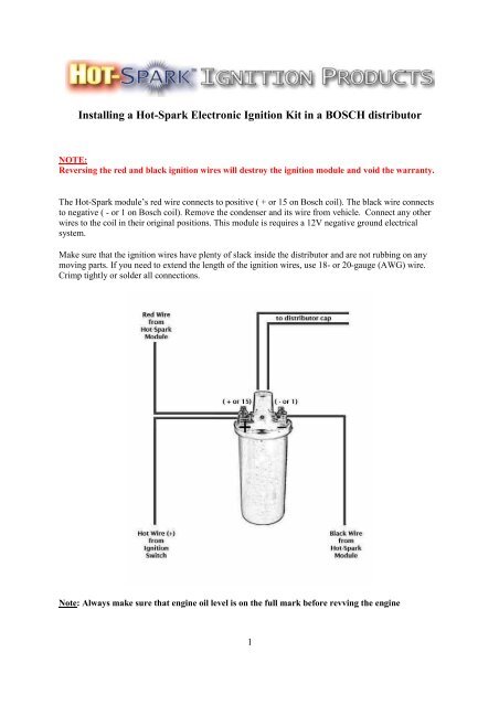
Revers<strong>in</strong>g the red and black ignition wires will destroy the ignition module and void the warranty.<br />
The <strong>Hot</strong>-<strong>Spark</strong> module’s red wire connects to positive ( + or 15 on Bosch coil). The black wire connects<br />
to negative ( - or 1 on Bosch coil). Remove the condenser and its wire from vehicle. Connect any other<br />
wires to the coil <strong>in</strong> their orig<strong>in</strong>al positions. This module is requires a 12V negative ground electrical<br />
system.<br />
Make sure that the ignition wires have plenty of slack <strong>in</strong>side the <strong>distributor</strong> and are not rubb<strong>in</strong>g on any<br />
mov<strong>in</strong>g parts. If you need to extend the length of the ignition wires, use 18- or 20-gauge (AWG) wire.<br />
Crimp tightly or solder all connections.<br />
Note: Always make sure that eng<strong>in</strong>e oil level is on the full mark before revv<strong>in</strong>g the eng<strong>in</strong>e<br />
1
Prior to <strong>in</strong>stall: After removal of the breaker po<strong>in</strong>ts, clean the <strong>distributor</strong>’s breaker po<strong>in</strong>ts plate<br />
thoroughly, so that the ignition module’s base plate makes good thermal contact with the <strong>distributor</strong>.<br />
Coil to use: Stock Bosch coil or HS15HEC high-energy coil OK. Coil should have 1.5 Ohms or more<br />
primary resistance. To measure primary resistance: Label and remove all wires to coil. Us<strong>in</strong>g a common<br />
digital multimeter <strong>in</strong> the 200 Ω mode, measure between coil’s + and - term<strong>in</strong>als. Allow a few seconds for<br />
the read<strong>in</strong>g to settle downward, until it stabilizes. Subtract about 0.3 Ohms from the read<strong>in</strong>g to<br />
compensate for multimeter’s <strong>in</strong>herent resistance.<br />
For best performance, the coil should also have a m<strong>in</strong>imum of 7,000 Ohms secondary resistance<br />
(measured from coil’s + or – term<strong>in</strong>al to center high tension term<strong>in</strong>al, <strong>in</strong> the 20K Ω mode of the<br />
Ohmmeter). Note: Do not use a low-resistance coil, such as the MSD or Accel coil - they don’t have<br />
enough primary resistance for this application. Us<strong>in</strong>g a coil with too little primary resistance can cause the<br />
ignition module to overheat and fail, thus void<strong>in</strong>g the warranty.<br />
Test Maximum Charg<strong>in</strong>g System Voltage: If the charg<strong>in</strong>g system voltage, measured at the coil’s<br />
positive term<strong>in</strong>al, is more than 14.2 volts at 2,500+ RPM, the voltage regulator likely needs replac<strong>in</strong>g.<br />
Too much voltage can damage the ignition module and other electronic components.<br />
Air Gap between Magnet Sleeve and <strong>Ignition</strong> Sensor: The air gap should be approximately 0.8 mm<br />
(.030 <strong>in</strong>.), although exact gap is not critical. There should be sufficient gap to prevent the magnet sleeve<br />
from rubb<strong>in</strong>g aga<strong>in</strong>st the <strong>Hot</strong>-<strong>Spark</strong> sensor. If there's not a wide enough gap between the magnet sleeve<br />
and the ignition sensor, you can on some kits adjust the distance. On the kits that do not have this option,<br />
you can hold ignition base plate towards the position it needs to be maoved while tighten<strong>in</strong>g the set screw.<br />
If this is not enough you can try the follow<strong>in</strong>g: With the ignition module fastened to the <strong>distributor</strong>'s<br />
breaker plate, bend the top, red part of the ignition module away from the magnet sleeve slightly, to<br />
widen the gap a little. Don't pry aga<strong>in</strong>st the plastic magnet sleeve - it may break. Note: when mak<strong>in</strong>g<br />
adjustemts: do not over-tighten these nuts – apply no more than 5 ft. lbs. of torque! Use a nut driver, not a<br />
socket wrench.<br />
<strong>Ignition</strong> Tim<strong>in</strong>g: Set the ignition tim<strong>in</strong>g, with a stroboscopic light, to the <strong>distributor</strong>’s factory<br />
specification. The difference <strong>in</strong> <strong>distributor</strong> position with po<strong>in</strong>ts vs. electronic ignition can be as much as<br />
30 degrees or so clockwise or counterclockwise, so you’ll def<strong>in</strong>itely have to reset the tim<strong>in</strong>g.<br />
Example of <strong>Hot</strong>-<strong>Spark</strong> kit <strong>in</strong> a Bosch 009 non-vacuum-advance <strong>distributor</strong><br />
2
1. Turn off the ignition switch and/or remove the ground strap from the battery. Though not absolutely<br />
necessary, it is probably easiest overall to remove the <strong>distributor</strong> from the car before <strong>in</strong>stall<strong>in</strong>g the <strong>Hot</strong>-<br />
<strong>Spark</strong> module. If the contacts <strong>in</strong> the <strong>in</strong>side of the <strong>distributor</strong> cap are worn or damaged, replace the<br />
<strong>distributor</strong> cap. Replace the rotor if it’s worn.<br />
2. Remove <strong>distributor</strong> cap, leav<strong>in</strong>g the plug wires <strong>in</strong> place, unless replac<strong>in</strong>g the <strong>distributor</strong> cap as well.<br />
3. Remove po<strong>in</strong>ts, condenser and the condenser’s wire from the vehicle. If there is a wire that used to go<br />
to the condenser, tape it off, as it will no longer be used. Because the <strong>Hot</strong>-<strong>Spark</strong> kit does not modify the<br />
<strong>distributor</strong>, the po<strong>in</strong>ts and condenser can be re<strong>in</strong>stalled at a later time.<br />
4. Install the screws that attached the condenser and its grommet back <strong>in</strong>to their holes. If the screws are<br />
now too long, use a washer or two on the screws.<br />
5. Clean any grease or dirt thoroughly from the <strong>distributor</strong>’s po<strong>in</strong>ts cam and the breaker po<strong>in</strong>ts plate.<br />
6. Insert the <strong>Hot</strong>-<strong>Spark</strong> module’s wires, one at a time, from the <strong>in</strong>side of the <strong>distributor</strong> out, through the<br />
hole <strong>in</strong> the side of the <strong>distributor</strong>. You can use a narrow, flat-bladed screwdriver to gently push the edges<br />
of the grommet from the <strong>in</strong>side of the <strong>distributor</strong>. Gently pull and rock, up-and-down and side-to-side, the<br />
rubber grommet, halfway through the hole, until it seats.<br />
7. Apply a very th<strong>in</strong> coat of the <strong>in</strong>cluded thermal transfer grease to the bottom of the ignition base plate.<br />
Place the <strong>Hot</strong>-<strong>Spark</strong> module’s bottom plate onto the <strong>distributor</strong>’s breaker plate. The peg should fit snugly<br />
<strong>in</strong>to the hole <strong>in</strong> the breaker plate and the screw holes should l<strong>in</strong>e up. The <strong>Hot</strong>-<strong>Spark</strong> module’s base plate<br />
should lie flat and snug on the <strong>distributor</strong>’s breaker plate. Insert the screw and tighten.<br />
8. Check to see if the vacuum advance is work<strong>in</strong>g properly by suck<strong>in</strong>g on the vacuum canister port. The<br />
breaker plate should move smoothly and freely.<br />
9. Press the magnet sleeve down on the rotor shaft. Next <strong>in</strong>stall the rotor on top of the magnet sleeve. The<br />
rotor should slide all the way down and lock <strong>in</strong>to place, so that it cannot turn <strong>in</strong>dependently of the<br />
<strong>distributor</strong> shaft. If you can still turn the rotor <strong>in</strong>dependently of the <strong>distributor</strong> shaft, the magnet sleeve is<br />
not seated all the way down. Be sure that the <strong>in</strong>dentations <strong>in</strong>side the magnet sleeve l<strong>in</strong>e up with the lobes<br />
of the <strong>distributor</strong> cam - turn the magnet sleeve on the <strong>distributor</strong> shaft until you can feel it l<strong>in</strong>e up.<br />
10. Adjust the two <strong>Hot</strong>-<strong>Spark</strong> ignition wires so that they have plenty of slack <strong>in</strong>side the <strong>distributor</strong> and<br />
they’re not rubb<strong>in</strong>g on any mov<strong>in</strong>g parts.<br />
11. Install the <strong>distributor</strong> cap and re<strong>in</strong>stall the <strong>distributor</strong>. Be sure that the anti-chatter spr<strong>in</strong>g is <strong>in</strong> place <strong>in</strong><br />
the <strong>distributor</strong> drive gear <strong>in</strong> the bottom of the <strong>distributor</strong> shaft hole.<br />
12. The <strong>Hot</strong>-<strong>Spark</strong> module’s red wire connects to positive ( + or 15 on Bosch coil). The black wire<br />
connects to negative ( - or 1 on Bosch coil). DO NOT reverse the polarity of these wires or the ignition<br />
module will be destroyed.<br />
13. Check all wire connections, <strong>in</strong>clud<strong>in</strong>g the two <strong>Hot</strong>-<strong>Spark</strong> wires and the spark plug and coil hightension<br />
wires. If you need to extend the length of the wires, use 18- or 20-gauge wire. We recommend<br />
solder<strong>in</strong>g all splices and connections, if you can, or crimp all connections tightly. Make doubly sure that<br />
all wires are connected to the proper term<strong>in</strong>als, etc. before reconnect<strong>in</strong>g the battery or turn<strong>in</strong>g the ignition<br />
switch to the ON position. Make sure that all connectors are snug.<br />
3
Tim<strong>in</strong>g:<br />
You can set the tim<strong>in</strong>g statically to about 0° (TDC) at first, so that the eng<strong>in</strong>e will start. Start the eng<strong>in</strong>e<br />
and tweak the tim<strong>in</strong>g until the eng<strong>in</strong>e runs by itself. Time the eng<strong>in</strong>e with a stroboscopic light <strong>in</strong> the<br />
normal manner. Although the <strong>in</strong>itial tim<strong>in</strong>g can be set roughly, f<strong>in</strong>al tim<strong>in</strong>g sett<strong>in</strong>gs need to be set us<strong>in</strong>g a<br />
stroboscopic tim<strong>in</strong>g light. This will probably be the last time you have to set the tim<strong>in</strong>g for a long time, so<br />
it’s worth it to spend the extra time and effort to set the tim<strong>in</strong>g absolutely spot-on accurately. An eng<strong>in</strong>e<br />
with its tim<strong>in</strong>g set to perfection will start with the slightest bump of the starter and purr like a kitten at idle<br />
– someth<strong>in</strong>g to make you feel good every time you start the eng<strong>in</strong>e.<br />
Sett<strong>in</strong>g tim<strong>in</strong>g on VW’s:<br />
TDC = Top Dead Center, or 0° BTDC = Before Top Dead Center ATDC = After Top Dead Center<br />
It’s hard to say which <strong>distributor</strong> an old air-cooled VW actually has <strong>in</strong> place. The orig<strong>in</strong>al stock<br />
<strong>distributor</strong> could very well have been replaced with a different <strong>distributor</strong> over the years. Bosch<br />
<strong>distributor</strong>s for VW have a Bosch number stamped on their side similar to 0 231 xxx xxx. Distributors<br />
may also have a VW number, which is preceded by a VW (and maybe an Audi) symbol. It’s most useful<br />
to f<strong>in</strong>d the Bosch number and look up the tim<strong>in</strong>g specifications for that particular VW <strong>distributor</strong> here on<br />
http://www.oldvolkshome.com/ignition.htm<br />
F<strong>in</strong>d<strong>in</strong>g Tim<strong>in</strong>g Marks on Type I VW Eng<strong>in</strong>e (Beetle, Ghia, Th<strong>in</strong>g, pre-1972 Bus, etc.): There are<br />
several different versions of stock crankshaft pulleys that came with Type I VW eng<strong>in</strong>es over the years,<br />
each hav<strong>in</strong>g its own set of notches (tim<strong>in</strong>g marks) <strong>in</strong> different places relative to TDC - very confus<strong>in</strong>g.<br />
Like the <strong>distributor</strong>, the pulley may have been swapped out several times over the years, so you don’t<br />
know what the notches on it mean. It’s possible to f<strong>in</strong>d TDC and other degree positions on a “mystery”<br />
VW pulley - it’s a tedious process, though.<br />
It’s much easier to replace an old Type I VW eng<strong>in</strong>e’s “mystery” crankshaft pulley with an aftermarket<br />
alum<strong>in</strong>um pulley of stock diameter, with degree mark<strong>in</strong>gs etched on it. Not only does it make sett<strong>in</strong>g the<br />
tim<strong>in</strong>g much easier; it’s also handy for check<strong>in</strong>g valve clearance, etc.<br />
Warn<strong>in</strong>g: Us<strong>in</strong>g an aftermarket pulley of smaller than stock diameter causes slower sp<strong>in</strong>n<strong>in</strong>g of the<br />
eng<strong>in</strong>e’s squirrel-cage fan, reduc<strong>in</strong>g the volume of air cool<strong>in</strong>g the eng<strong>in</strong>e, possibly result<strong>in</strong>g <strong>in</strong><br />
overheat<strong>in</strong>g and premature eng<strong>in</strong>e failure. These smaller-diameter pulleys are often marketed as “Hi-<br />
Performance” or “Power” pulleys. They are okay for rac<strong>in</strong>g use, where the eng<strong>in</strong>e is always run at high<br />
RPM levels. For daily driv<strong>in</strong>g, we recommend a stock-sized pulley for better eng<strong>in</strong>e cool<strong>in</strong>g.<br />
Tim<strong>in</strong>g the Bosch 009 or 050 Centrifugal-Advance Distributor (VW or Porsche only): Use a<br />
stroboscopic tim<strong>in</strong>g light and tach/dwell meter or tachometer, regardless of whether the <strong>distributor</strong> is<br />
equipped with po<strong>in</strong>ts or an electronic ignition module. Static tim<strong>in</strong>g at around 0° (TDC) is suitable only<br />
for the <strong>in</strong>itial adjustment, <strong>in</strong> order to get the eng<strong>in</strong>e runn<strong>in</strong>g. To set the tim<strong>in</strong>g accurately, you must use a<br />
stroboscopic light connected to No. 1 cyl<strong>in</strong>der’s spark plug wire. Set the tim<strong>in</strong>g with the eng<strong>in</strong>e runn<strong>in</strong>g at<br />
3,200+ RPM, so that the tim<strong>in</strong>g is fully advanced. The 009’s tim<strong>in</strong>g should be set no further advanced<br />
than 30° BTDC at 3,200+ RPM.<br />
You can locate the 30° BTDC spot on a stock VW Type I crankshaft pulley, which has a 175 mm (6-7/8<br />
<strong>in</strong>.) diameter, by measur<strong>in</strong>g, clockwise, from top dead center, around the circumference of the pulley,<br />
45.8 mm, or 1-13/16 <strong>in</strong>. Make a small white pa<strong>in</strong>t mark there. That’s about 30° BTDC.<br />
Tim<strong>in</strong>g a Stock, Air-Cooled VW Vacuum-advance Distributor: A stock, vacuum-advance <strong>distributor</strong><br />
should be timed with a stroboscopic light and tach/dwell meter, accord<strong>in</strong>g to the specifications <strong>in</strong> the VW<br />
service manual.<br />
4
For dual vacuum-advance <strong>distributor</strong>s (with vacuum canisters hav<strong>in</strong>g two vacuum ports): You can locate<br />
the 5° ATDC spot on a stock VW Type I crankshaft pulley, which has a 175 mm (6-7/8 <strong>in</strong>.) diameter, by<br />
measur<strong>in</strong>g, counterclockwise, from TDC, around the circumference of the pulley, 7.6 mm (5/16 <strong>in</strong>.). Pa<strong>in</strong>t<br />
a small white mark here. This is about 5 o ATDC, the po<strong>in</strong>t at which the dual vacuum-advance <strong>distributor</strong><br />
(its vacuum canister has two vacuum ports) is usually timed at idle. Refer to the official VW Service<br />
Manual for the proper tim<strong>in</strong>g specifications for the <strong>distributor</strong> used <strong>in</strong> your vehicle.<br />
For SVDA (s<strong>in</strong>gle vacuum, dual advance) <strong>distributor</strong>s: You can locate the 7.5° BTDC spot on a stock<br />
VW Type I crankshaft pulley, which has a 175 mm (6.895 <strong>in</strong>.) diameter, by measur<strong>in</strong>g, clockwise (to the<br />
right), from TDC, around the circumference of the pulley, 11.45 mm (7/16 <strong>in</strong>.). Pa<strong>in</strong>t a small white mark<br />
here. This is the po<strong>in</strong>t at which the centrifugal advance (009) and certa<strong>in</strong> s<strong>in</strong>gle-vacuum, dual-advance<br />
(SVDA) <strong>distributor</strong>s (their vacuum canister has only one vacuum port) are timed at idle. Aga<strong>in</strong>, refer to<br />
the official VW Service Manual for the proper tim<strong>in</strong>g specifications for the <strong>distributor</strong> used <strong>in</strong> your<br />
vehicle.<br />
Volvo-PENTA Mar<strong>in</strong>e eng<strong>in</strong>es with Bosch <strong>distributor</strong><br />
Make sure that there's enough space between the ignition sensor and the magnet sleeve. Sometimes, the<br />
screw that attaches the <strong>distributor</strong> cap clip to the <strong>distributor</strong> body protrudes too far <strong>in</strong>to the <strong>distributor</strong>,<br />
crowd<strong>in</strong>g the ignition module too close to the magnet sleeve. You’ll probably have to add one or two<br />
extra washers to the <strong>distributor</strong> cap clip screw, to keep the screw from stick<strong>in</strong>g too far <strong>in</strong>to the <strong>distributor</strong>.<br />
Then, loosen the set screw that holds the ignition module base plate. Hold the ignition base plate away<br />
from the magnet sleeve slightly, while retighten<strong>in</strong>g the ignition module set screw. There should be a gap<br />
of about 0.8mm (.030 <strong>in</strong>.) between the magnet sleeve and the ignition module, although the exact gap is<br />
not critical. To <strong>in</strong>crease air gap slightly, hold ignition base plate away from <strong>distributor</strong> shaft while<br />
tighten<strong>in</strong>g set screw.<br />
The Volvo-Penta <strong>distributor</strong> uses an 8mm (5/16”) O.D. round rubber grommet. You’ll have to cut the<br />
spade connectors off the two ignition wires. Pass the wires, from the <strong>in</strong>side of the <strong>distributor</strong> out, through<br />
the round hole <strong>in</strong> the side of the <strong>distributor</strong> body and then through the round rubber grommet. Seat the<br />
grommet <strong>in</strong> the hole. Crimp or solder new ¼” (6.37mm) female quick-connect term<strong>in</strong>al connectors onto<br />
the ends of the wires.<br />
Typically, a purple wire goes to the condenser on the Volvo-Penta <strong>distributor</strong>. When <strong>in</strong>stall<strong>in</strong>g the <strong>Hot</strong>-<br />
<strong>Spark</strong> ignition, remove the po<strong>in</strong>ts and condenser and tape off the purple wire, as it will no longer be used.<br />
5
Clean<strong>in</strong>g, lubricat<strong>in</strong>g and check<strong>in</strong>g:<br />
Lubricat<strong>in</strong>g: You likely won’t have the <strong>distributor</strong> out of the eng<strong>in</strong>e aga<strong>in</strong> for some time. So now is a<br />
good time to lubricate under the vacuum advance plate, the <strong>distributor</strong> shaft and its bush<strong>in</strong>g and the<br />
sw<strong>in</strong>g<strong>in</strong>g centrifugal advance weights <strong>in</strong> the bottom of the <strong>distributor</strong>. You can access the centrifugal<br />
advance weights easily by remov<strong>in</strong>g the curved plug on the outside of the <strong>distributor</strong>, near the bottom. A<br />
somewhat sharp, flat-bladed putty knife is handy for pry<strong>in</strong>g off this plug. A small amount of heavy oil,<br />
such as 90W hypoid, synthetic heavy transmission oil or heavy motor oil works well for lubricat<strong>in</strong>g the<br />
<strong>distributor</strong>. Don’t use a th<strong>in</strong> solvent, such as WD-40, for lubrication, as its lubricat<strong>in</strong>g qualities won’t last<br />
for long. Apply a few drops of oil to the felt wick under the rotor. Clean up any excess oil or grease.<br />
Vacuum canister check: If your eng<strong>in</strong>e uses a vacuum-advance <strong>distributor</strong>, test the vacuum canister by<br />
suck<strong>in</strong>g hard on its vacuum port. The vacuum advance plate, under the po<strong>in</strong>ts, should move<br />
counterclockwise and clockwise noticeably and freely when you do this repeatedly. If you suck and then<br />
cover the vacuum port with your tongue, the vacuum advance plate should stay <strong>in</strong> the same position until<br />
you lift your tongue. If it drifts back before you lift your tongue, the diaphragm is leak<strong>in</strong>g and it won’t<br />
advance the tim<strong>in</strong>g properly. In that case you need to replace the vacuum canister or the entire <strong>distributor</strong>.<br />
If the <strong>distributor</strong> is dirty and covered with gunk <strong>in</strong>side and out, you may need to soak it <strong>in</strong> a solvent such<br />
as naphtha or kerosene (don’t allow solvent to leak <strong>in</strong>to the vacuum canister - remove the vacuum canister<br />
first). After soak<strong>in</strong>g and scrubb<strong>in</strong>g with a stiff nylon brush, r<strong>in</strong>se thoroughly with clean solvent, dry with<br />
compressed air or allow to air-dry and lubricate the shaft, bush<strong>in</strong>g, advance weights and breaker advance<br />
plate. Wipe up excess grease and oil. If the vacuum advance plate still doesn’t move freely, you may need<br />
to replace the vacuum canister or replace the <strong>distributor</strong>.<br />
Test<strong>in</strong>g the Coil’s <strong>Spark</strong>: Beg<strong>in</strong> with a fully charged battery. Disconnect the high-tension cable from the<br />
center term<strong>in</strong>al of the <strong>distributor</strong> cap. Hold it about 10 mm (3/8”) from the eng<strong>in</strong>e crankcase. (Be sure that<br />
you’re very well <strong>in</strong>sulated from the end of the high-tension cable or many thousands of volts could course<br />
through your body!) Have a helper crank the eng<strong>in</strong>e while you watch the spark produced. A weak coil<br />
will produce an anemic yellowish or orange spark; it might fire only when the cable is moved close to the<br />
crankcase or it won’t fire at all. A healthy coil will produce a bright bluish-white spark with a loud,<br />
dist<strong>in</strong>ct CRACK! sound. If your coil doesn’t produce a strong, whitish-bluish spark, you should replace it.<br />
Distributor Cap and Rotor: Stock rotors and <strong>distributor</strong> caps work f<strong>in</strong>e with the <strong>Hot</strong>-<strong>Spark</strong> module. A<br />
worn, corroded or scored <strong>distributor</strong> cap and/or rotor is often the cause of the tim<strong>in</strong>g jump<strong>in</strong>g around<br />
erratically at idle. With the <strong>Hot</strong>-<strong>Spark</strong> electronic ignition <strong>in</strong>stalled <strong>in</strong> place of po<strong>in</strong>ts, several times as<br />
much voltage surges through the rotor to the <strong>distributor</strong> cap term<strong>in</strong>al contacts. While the rotor and<br />
<strong>distributor</strong> cap may have functioned alright with po<strong>in</strong>ts, the <strong>in</strong>creased stra<strong>in</strong> of double the voltage may be<br />
too much for the old, worn rotor and <strong>distributor</strong> cap. We recommend <strong>in</strong>stall<strong>in</strong>g a new <strong>distributor</strong> cap and<br />
rotor when convert<strong>in</strong>g from po<strong>in</strong>ts to electronic ignition.<br />
<strong>Spark</strong> Plug Gap: With the <strong>Hot</strong>-<strong>Spark</strong> ignition kit, the stock spark plug gap specification is f<strong>in</strong>e. For<br />
rac<strong>in</strong>g purposes, you can <strong>in</strong>crease the spark plug gap by about .005 <strong>in</strong>ches, or .12 mm. Be aware that<br />
chang<strong>in</strong>g the spark plug gap can affect the tim<strong>in</strong>g - you should recheck the ignition tim<strong>in</strong>g if you change<br />
the spark plug gap.<br />
6
Us<strong>in</strong>g <strong>Hot</strong>-<strong>Spark</strong> <strong>Ignition</strong> with MSD Blaster:<br />
Refer to this diagram to use the <strong>Hot</strong>-<strong>Spark</strong> <strong>Ignition</strong> with the MSD (Multiple <strong>Spark</strong> Discharge) Blaster:<br />
<strong>Hot</strong>-<strong>Spark</strong> <strong>Ignition</strong> and MSD 6 Series Wir<strong>in</strong>g Diagram:<br />
7
Volvo 1800 with tachometer:<br />
Refer to this diagram to use the <strong>Hot</strong>-<strong>Spark</strong> <strong>Ignition</strong> with the Volvo 1800 Tachometer:<br />
8
Limited Warranty: <strong>Hot</strong>-<strong>Spark</strong> <strong>Ignition</strong> Products warrants its electronic ignition conversion kits to be free from<br />
defects <strong>in</strong> material and workmanship under normal use and if properly <strong>in</strong>stalled for a period of three years from date<br />
of purchase. If found to be defective as mentioned above, it will be replaced or repaired if returned prepaid along<br />
with proof of date of purchase. Warranty shall be null and void if it is determ<strong>in</strong>ed that said electronic ignition<br />
conversion kit has been connected improperly, if it is used with an ignition coil which has <strong>in</strong>sufficient resistance <strong>in</strong><br />
its primary circuit or if the polarity of the electrical wir<strong>in</strong>g of the ignition kit has been reversed.<br />
This shall constitute the sole remedy of the purchaser and the sole liability of <strong>Hot</strong>-<strong>Spark</strong> <strong>Ignition</strong> Products. To the<br />
extent permitted by law, the forego<strong>in</strong>g is exclusive and <strong>in</strong> lieu of all other warranties or representations whether<br />
expressed or implied, <strong>in</strong>clud<strong>in</strong>g any implied warranty of merchantability or fitness. In no event shall <strong>Hot</strong>-<strong>Spark</strong><br />
<strong>Ignition</strong> Products be liable for special or consequential damages.<br />
www.<strong>Hot</strong>-<strong>Spark</strong>.eu<br />
© 2007 <strong>Hot</strong>-<strong>Spark</strong> TM <strong>Ignition</strong> Products<br />
9