analog to digital converter . . . . . . . . . . . . . . . 4 - UPGNet
analog to digital converter . . . . . . . . . . . . . . . 4 - UPGNet
analog to digital converter . . . . . . . . . . . . . . . 4 - UPGNet

Create successful ePaper yourself
Turn your PDF publications into a flip-book with our unique Google optimized e-Paper software.
351579-YTS-B-0608TECHNICAL APPLICATIONANDPROGRAMMING GUIDEMILLENNIUM ® SINGLE PACKAGEROOFTOP UNITS25, 30 & 40 TON EQUIPPED WITHSIMPLICITY ® ELITE CONTROLSMILLENNIUM ® 25-40 TON SINGLE PACKAGECOMMERCIAL ROOFTOP UNIT EQUIPPEDWITH SIMPLICITY ® CONTROLSThis manual includes application, programming and serviceprocedures for the Millennium ® 25-40 Ton Single PackageCommercial Roof<strong>to</strong>p Unit equipped with Simplicity ® Controls.These procedures are the same for all 25-40 Ton Millennium ®Roof<strong>to</strong>p units in this series except as noted.This manual covers Simplicity ® controls only, for unit installationinformation please refer <strong>to</strong> the following.RECOMMENDED TECHNICAL ANDINSTALLATION AIDSMillennium ® 25-40 Ton Single Package Installation and OperationManual - 336043Millennium ® 25-40 Ton Technical Guide - 246653ISO 9001Certified QualityManagement System
351579-YTS-B-0608TABLE OF CONTENTSMILLENNIUM® 25-40 TON SINGLE PACKAGECOMMERCIAL ROOFTOP UNIT EQUIPPED WITHSIMPLICITY® CONTROLS . . . . . . . . . . . . . . . . . . . . 1RECOMMENDED TECHNICAL ANDINSTALLATION AIDS . . . . . . . . . . . . . . . . . . . . . . . . 1THE MILLENNIUM® SIMPLICITY® CONTROL . . . . 3INTRODUCTION AND OVERVIEW . . . . . . . . . . . . . . . . . 3DIGITAL LINGO . . . . . . . . . . . . . . . . . . . . . . . . . . . . . . . . 4ANALOG TO DIGITAL CONVERTER . . . . . . . . . . . . . . . 4COMMUNICATIONS BUS . . . . . . . . . . . . . . . . . . . . . . . . 5OPTIONAL MODLINC TRANSLATOR. . . . . . . . . . . . . . . 5COMPONENT DESCRIPTION. . . . . . . . . . . . . . . . . . . . . 5SIMPLICITY® PROGRAMMING OPTIONS . . . . . . . 11INTERACTING THROUGH THE MILLENNIUM®SIMPLICITY® . . . . . . . . . . . . . . . . . . . . . . . . . . . . . . . . 11INITIAL STARTUP OPTIONS . . . . . . . . . . . . . . . . . . . . 11METRIC OPERATION (ENGLISH) . . . . . . . . . . . . . . . . 11SETTABLE SYSTEM PARAMETERS . . . . . . . . . . . 11MILLENNIUM® SEQUENCE OF OPERATION . . . . 18OVERVIEW . . . . . . . . . . . . . . . . . . . . . . . . . . . . . . . . . . 18RUN SEQUENCE. . . . . . . . . . . . . . . . . . . . . . . . . . . . . . 18UNIT CONTROLS SEQUENCE . . . . . . . . . . . . . . . . . . . 18VARIABLE AIR VOLUME UNIT (VFD & IGV) . . . . . . . . 20OCCUPIED / UNOCCUPIED / MORNING WARM-UP . 21UNIT CONTROLS . . . . . . . . . . . . . . . . . . . . . . . . . . . . . 21HEAD PRESSURE CONTROL . . . . . . . . . . . . . . . . . . . 26SEQUENCE OF OPERATION - FOR HEAD PRESSURECONTROL. . . . . . . . . . . . . . . . . . . . . . . . . . . . . . . . . . . 26INTELLI-START . . . . . . . . . . . . . . . . . . . . . . . . . . . . . . . 27DEVICES AND RULES . . . . . . . . . . . . . . . . . . . . . . . . . 27COMFORT VENTILATION MODE . . . . . . . . . . . . . . . . . 28HYDRONIC HEAT . . . . . . . . . . . . . . . . . . . . . . . . . . . . . 29COOLING LOCKOUT ON OAT . . . . . . . . . . . . . . . . . . . 29WATER COIL FREEZE STAT (FSI). . . . . . . . . . . . . . . . 29CV OPERATION . . . . . . . . . . . . . . . . . . . . . . . . . . . . . . 29THERMOSTAT OPERATION FOR COOLING WITH Y1,Y2, Y3 AND Y4 INPUTS . . . . . . . . . . . . . . . . . . . . . . . . 30OPERATION FOR HEATING WITH W1, W2, AND W3INPUTS . . . . . . . . . . . . . . . . . . . . . . . . . . . . . . . . . . . . . 30SENSOR OPERATION . . . . . . . . . . . . . . . . . . . . . . . . . 30TYPES OF SPACE SENSORS . . . . . . . . . . . . . . . . . . . 31VAV OPERATION . . . . . . . . . . . . . . . . . . . . . . . . . . . . . 32SUPPLY DUCT PRESSURE CONTROL ALGORITHM. 34MORNING WARM UP / VAV OCCUPIED HEATINGCONTROL ALGORITHM . . . . . . . . . . . . . . . . . . . . . . . 34CONTROLLING EXCESSIVE SAT (SUPPLY AIRTEMPERATURE) . . . . . . . . . . . . . . . . . . . . . . . . . . . . . .35SAT SETPOINTS USED DURING COOLING WITHECONOMIZER OPERATION . . . . . . . . . . . . . . . . . . . . .36DEMAND VENTILATION . . . . . . . . . . . . . . . . . . . . . . . . .39EXHAUST OPERATION . . . . . . . . . . . . . . . . . . . . . . . . .40SCHEDULING OPERATION . . . . . . . . . . . . . . . . . . . . . .41COMPRESSOR STATUS MONITORING . . . . . . . . . . . .41TROUBLESHOOTING A MILLENNIUM®SIMPLICITY® CONTROL . . . . . . . . . . . . . . . . . . . . 43STATUS LED CHART . . . . . . . . . . . . . . . . . . . . . . . . . . .43FAILURE MODES AND DEFAULT OPERATION . . . . . .43SENSOR FAILURES AND DEFAULT OPERATION . . . .43SYSTEM ERRORS . . . . . . . . . . . . . . . . . . . . . . . . . . . . .44LIST OF FIGURESFig. # Pg. #1 SIMPLICITY® CONTROLLER . . . . . . . . . . . . . . . . . . . 32 SIMPLICITY® CONTROLS PUSH BUTTONS . . . . . . 33 ANALOG TO DIGITAL CONVERTER . . . . . . . . . . . . . 44 VFD CONTROL WIRING . . . . . . . . . . . . . . . . . . . . . . . 85 SEQUENCE OF SETTING THE SET POINTS . . . . . 146 COMFORT VENTILATION ECONOMIZERCONTROL . . . . . . . . . . . . . . . . . . . . . . . . . . . . . . . . . .287 SAT CONTROL BAND . . . . . . . . . . . . . . . . . . . . . . . 34LIST OF TABLESTbl. # Pg. #1 ACRONYMS . . . . . . . . . . . . . . . . . . . . . . . . . . . . . . . . 62 INPUT SIGNAL TO Y1 ACTUATOR POSITION . . . . . 83 SIMPLICITY® CONTROL INPUTS . . . . . . . . . . . . . . . 94 SIMPLICITY® CONTROL OUTPUTS . . . . . . . . . . . . 105 SETTABLE SYSTEM PARAMETERS . . . . . . . . . . . . 166 COOLING STAGE . . . . . . . . . . . . . . . . . . . . . . . . . . . 197 IGNITION CONTROL BOARD FLASH CODES . . . . 238 MODULATING GAS HEAT . . . . . . . . . . . . . . . . . . . . 249 MODULATING GAS HEAT CONTROL BOARD FLASHCODES . . . . . . . . . . . . . . . . . . . . . . . . . . . . . . . . . . . .2510 COMPRESSOR MINIMUM OFF TIMES . . . . . . . . . . 3011 WEEKLY SCHEDULE . . . . . . . . . . . . . . . . . . . . . . . . 3412 HOLIDAY SCHEDULE. . . . . . . . . . . . . . . . . . . . . . . . 3513 ALARM DEFAULT CODES . . . . . . . . . . . . . . . . . . . . 4214 STATUS LED CHART . . . . . . . . . . . . . . . . . . . . . . . . 432 Johnson Controls Unitary Products
351579-YTS-B-0608THE MILLENNIUM ® SIMPLICITY ® CONTROLINTRODUCTION AND OVERVIEWWelcome <strong>to</strong> the new Millennium ® Simplicity ® control, a <strong>digital</strong>control system designed specifically for the Millennium ® 25 <strong>to</strong> 40Ton single package roof<strong>to</strong>p unit. The Simplicity ® is composed of72 moni<strong>to</strong>red and controlled input and output points. The controllogic of the Simplicity ® extends on the rules built in <strong>to</strong> theSynthesys control, and provides character displays in addition <strong>to</strong>LED flashes <strong>to</strong> display information <strong>to</strong> the technician.The Simplicity ® <strong>digital</strong> control performs all of the control andmoni<strong>to</strong>ring functions that were originally done by separatediscrete relays, controls, and interlocking hardware. Thisreduces manufacturing, service, and maintenance costs. TheSimplicity ® <strong>digital</strong> controller includes sophisticated control ofthe individual components of the HVAC cooling/heating unit,and has built-in rules that protect those components andoptimize the control <strong>to</strong> its environment. The cooling and heatingmodes are protected against frequent cycling, slugging,multiple restarts, etc.The Millennium ® Simplicity ® control is resis<strong>to</strong>r-configured forConstant Volume (CV) units or Variable Air Volume (VAV) units.The option settings for a specific option configuration will bemade as part of unit test at the fac<strong>to</strong>ry; however, if there isdoubt about how a unit is responding in the field, check theoption setting for the unexplained action.If connected <strong>to</strong> a network, the control requests an address by apress of the Address/Down but<strong>to</strong>n.DIAGNOSTICS VIA LEDThere is an LED on the board that shows the status of thecontrol and alarms (see Status LED Table). There are twocharacter displays, one 2-digit and one 4-digit, <strong>to</strong> indicatedetails of run conditions and alarms (see Alarms Table in theTrouble Shooting section of this manual).When the Alarm / Change Data but<strong>to</strong>n (See Figure 2 Simplicity ®Controller Push But<strong>to</strong>ns) is pushed and released one time withinfive seconds, it will re-enunciate the last five alarms on theDisplay.ProgramTest / Reset / UpAlarms / Change DataAddress / DownFigure 1: Simplicity ® ControllerOne result is that the system may not immediately respond asyou expect. For example, internal <strong>digital</strong> timers may delay thestart of a compressor even though the thermostat calls forcooling. The control may be in the middle of a timing sequence;without the observer knowing what has already happened andthe status of current inputs, the system may take action notexpected by the tech.In the Simplicity ® control, there are:• a list of user-selected option settings and setpointsrecorded within the control;• inputs moni<strong>to</strong>red by the Simplicity ® ;• specific fixed rules and timings built in <strong>to</strong> the control• outputs <strong>to</strong> compressors, heat, economizers, and otheroptions.The Simplicity ® has a real-time clock function, with minimum often hours “Time-of-day retention” with unit power off.Figure 2: Simplicity ® Controls Push But<strong>to</strong>nsWhen this but<strong>to</strong>n is pushed and released two times within fiveseconds, it will clear all s<strong>to</strong>red alarms.The error details for most conditions are s<strong>to</strong>red in summary inthe Simplicity ® Control and can be accessed by the <strong>digital</strong>display, personal computer interface, or Palm Pilot (Someinterfaces still in development).Diagnosing requires patience because of internal timings.Normal observable conditions are the same - contac<strong>to</strong>r 1Mpulled in, compressor 1 running - but the control does notidentify what it has just done or is about <strong>to</strong> do. The Simplicity ®control will take action according <strong>to</strong> its internal rules eventhough action requests come from smart thermostats. A call forcooling, for example, will be compared with supply airtemperature before energizing a cooling stage.ERROR HISTORYThe Simplicity ® control s<strong>to</strong>res up <strong>to</strong> 5 of the most recent alarmsin a First In, First Out (FIFO) manner. As the control collectsJohnson Controls Unitary Products 3
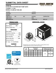
351579-YTS-B-0608alarms, it will overwrite the oldest alarm after the his<strong>to</strong>ry bufferbecomes full.Some system errors will initiate a controlling response as wellas being s<strong>to</strong>red in the error memory buffer. See the“Troubleshooting” chapter in this manual for a detaileddescription of how controller errors are handled.Data items s<strong>to</strong>red for maintenance / run his<strong>to</strong>ry, in addition <strong>to</strong>Alarms:• Accumulated run times for each compressor and heat stage• Unit model number• Unit serial number• Unit NameDIGITAL LINGOThis training manual is intended <strong>to</strong> help you with thecommissioning process by illustrating the use of <strong>to</strong>ols like thecontrol’s <strong>digital</strong> input and software engineered specifically forstarting up and servicing a Millennium ® roof<strong>to</strong>p unit.depending on how long the sensed value remains away from itsdesired setpoint.Fortunately, you do not have <strong>to</strong> determine all of theseparameters since they are pre-programmed at the fac<strong>to</strong>ry. Youneed only <strong>to</strong> set a desired setpoint and ensure that the inputsand outputs are properly wired and working. This is referred <strong>to</strong>as commissioning a system.ANALOG TO DIGITAL CONVERTERComputers can only understand a simple binary language.Remember, “binary” means two states - ON or OFF. Analog(continuous) values of voltages, currents, and resistances aresupplied by sensors and transducers <strong>to</strong> the control. Thesevalues must be converted in <strong>to</strong> a binary code so that thecomputer can understand them. This conversion process isperformed through a combination of hardware and software.For example, the 0-5VDC <strong>analog</strong> value from a static pressuretransducer is divided in<strong>to</strong> thousands of steps with a binarycoded number, often called “counts”, assigned <strong>to</strong> each step.You should become familiar with some common terminologyand lingo used in the <strong>digital</strong> controls industry. (If you are familiarwith the Synthesys controller, the logic of the Simplicity ® will befamiliar terri<strong>to</strong>ry.)If this is your first exposure <strong>to</strong> the world of <strong>digital</strong> controls youmay experience a lot of new terms, acronyms and technicallingo commonly used in the controls industry. For example, theSimplicity ® input and output hardware points are described as<strong>analog</strong>, relating <strong>to</strong> a continuous scale of value readings suchas a temperature sensor ranging from -40 0 F <strong>to</strong> 160 0 F range, orbinary, meaning 2-states, either on or off, open or closed, trueor false, one or zero. The term “<strong>digital</strong>” also means two statesand its use is often interchanged with “binary”. These pointsmay be either fac<strong>to</strong>ry- or field-set.THE PI ALGORITHMAnother common “<strong>digital</strong> controls” term is the PI algorithm orProportional-Integral control loop. The PI algorithm is acontinuously updated math calculation that the controller uses<strong>to</strong> modulate an <strong>analog</strong> output point. For example, a variablespeed drive uses a PI loop <strong>to</strong> maintain a desired setpoint (in thiscase, a duct static pressure value). The algorithm takes in<strong>to</strong>account several parameters <strong>to</strong> calculate the output. The PI loopneeds parameters such as the proportional operatingbandwidth, integral time constant, deadband, desired setpointvalue, sensed input value(s), start up ramp time, initial startvalue, maximum output control value, a status point <strong>to</strong> initiatethe control action (i.e. a fan ON status), Direct or ReverseControlling Action, and several other parameters <strong>to</strong> calculate asimple 0 <strong>to</strong> 100% <strong>analog</strong> output control. The PI algorithm is alsocalled a PI loop because it “loops” the output back <strong>to</strong> the input(feedback) and determines a new output value based on the“error” or difference between the setpoint value and the sensedinput value, and how that difference relates proportionally <strong>to</strong> the0 <strong>to</strong> 100% output value. Time is the ”integral” constant that isfac<strong>to</strong>red in <strong>to</strong> increase or decrease the controlling output action0 1 2 3 4 5 6 7------------- nFigure 3: Analog <strong>to</strong> Digital ConverterSOFTWARE TERMINOLOGYBINARY NUMBER EQUIVALENTA <strong>digital</strong> controller handles its control functions through softwareprogramming rather than with interlocking hardware and wiring.The software then becomes key <strong>to</strong> how controlled functions arehandled. Software is a set of statements (referred <strong>to</strong> as the“program”) that define the function of the controller’s internalmicroprocessor computer.Software procedurally tells the computer the sequence andorder of tasks that need <strong>to</strong> be performed using a language thatthe computer can understand.Software is s<strong>to</strong>red in a computer’s memory. There are severaltypes of memory in a computer. Each type has a specificfunction <strong>to</strong> perform.4 Johnson Controls Unitary Products
351579-YTS-B-0608EPROM - This is “nonvolatile” memory, meaning it will not beerased on a power loss. This memory is usually programmedprior <strong>to</strong> assembly of the controller. Since this memory is notchanged during normal operation of the Simplicity ® control, onlybasic operation instructions are s<strong>to</strong>red in this type of memory.EEPROM (Double “E” Prom) - Is also non-volatile, but thistype of memory requires a special process <strong>to</strong> be written <strong>to</strong>. Thismemory can be written <strong>to</strong> and changed by the microprocessor.This is the type of memory that the control program is s<strong>to</strong>red inthe Simplicity ® control.ROM - Read Only Memory is non-volatile but can not be written<strong>to</strong>. This memory is programmed only once before the controlleris assembled. ROM contains instructions specifically for theinternal microprocessor computer in the controller.FIRMWARE - “Firmware” is software, program instructions orapplications, but s<strong>to</strong>red in EPROM or ROM memory.RAM - Random Access Memory is a volatile memory. It will beerased when a power fail occurs. This memory is used as akind of “scratch pad” for the controller. Temporary instructionsand information such as an output controlling action like drivingthe economizer dampers open is s<strong>to</strong>red here. When a powerloss occurs or if the controller is sent a manual reset using acontrol push but<strong>to</strong>n, this memory is cleared and initialized.Other filtered inputs include temperature and humidity sensors.You should be aware of this filtering effect because it willappear the controller is not acting as fast as you may think itshould. In reality, it is acting and controlling on these timeaveragedand weighted values.FAULT TOLERANCE - Fault Tolerance of the Simplicity ® controlinvolves two issues: Hardware fault <strong>to</strong>lerance deals specificallywith the electrical characteristics of the controller - how muchover voltage or power surge the controller can withstand beforedamage occurs, and whether internal comparisons are verifyingthat the control is calculating and communicating properly.Software fault <strong>to</strong>lerance in this technology consists of comparingresults <strong>to</strong> previous values and <strong>to</strong> reasonable values.COMMUNICATIONS BUSNetworked communications may also be new <strong>to</strong> you. It relates<strong>to</strong> connecting several Millennium ® roof<strong>to</strong>p units <strong>to</strong> a networkthat can be moni<strong>to</strong>red and controlled remotely from networkcomputer workstations. You will find this typically on largeinstallations where central control, moni<strong>to</strong>ring, and energymanagement issues become a critical fac<strong>to</strong>r in operating alarge complex such as a manufacturing facility.The Simplicity ® Control has the ability <strong>to</strong> be networked in<strong>to</strong> alarger system using the MODBUS communication pro<strong>to</strong>col. Acommunication pro<strong>to</strong>col is simply a set of rules that determinehow two systems communicate with each other over somemedium such as a pair of wires, phone line, radio waves, etc.The transmission medium may also be called a gateway,pathway, or bus. An “open” pro<strong>to</strong>col such as MODBUS is apublicly published set of rules that any equipment manufacturercan use <strong>to</strong> network in<strong>to</strong> another manufacturers equipment.OPTIONAL ModLINC TRANSLATOROVERVIEWThe ModLINC transla<strong>to</strong>r operates as a Modbus ® Client providingan interface between a BACnet ® control system and devices thatcommunicate using the Modbus ® RTU pro<strong>to</strong>col. The ModLINC ispreconfigured <strong>to</strong> provide an interface <strong>to</strong> YORK UPG productsequipped with an Intelli-Comfort or Simplicity Elite controllerand allows moni<strong>to</strong>ring and control by a third-party BACnet ®Building Au<strong>to</strong>mation System (BAS).The ModLINC communicates using the Modbus ® RTU pro<strong>to</strong>colon one port and BACnet ® MS/TP. By providing differentcommunication pro<strong>to</strong>cols on the two ports, data can beretrieved from and provided <strong>to</strong> two different systems.The ModLINC mounts inside the control panel of the UPG unitand utilizes 24 VAC power from the unit's control transformer.One port is connected <strong>to</strong> the UPG controller. The other portmust be connected <strong>to</strong> the BACnet ® network.The ModLINC transla<strong>to</strong>r is preconfigured <strong>to</strong> obtain operationaldata points from the controller and expose them on a BACnet ®network."The ModLINC device is primary a control offered andconfigured by York's ESG (Engineering Systems Group). Thedevice is designed <strong>to</strong> tie in<strong>to</strong> and function with a BACnet ®MS/TP network. The device can be used with other BACnet ®MS/TP systems, but a qualified controls contrac<strong>to</strong>r must beinvolved. UPG cannot support the ModLINC device beyond itshardware functionality and cannot guarantee functionality withother third party BAS devices."Please refer <strong>to</strong> the ModLINC Installation/Application manualPart Number 126367.COMPONENT DESCRIPTIONThis section describes the main components of Millennium ®Simplicity ® control. These components consist primarily ofcontrollers, hardware <strong>to</strong> handle signal input and control outputand the Tstat interface terminals.THE Simplicity ® CONTROLLERSimplicity ® is a proprietary, microprocessor-based controller foruse in HVAC applications. The controller provides moni<strong>to</strong>ringand control for either VAV or CAV for a <strong>to</strong>tal of 22 outputs.WIRING AND TERMINATION, COMMUNICATIONSMost connections <strong>to</strong> the Simplicity ® Control are by wiringharnesses. There are also screw terminal connections forthermostat inputs and for communications via an RS-485 port.COMMUNICATION ADDRESSThe communication address but<strong>to</strong>n (lower right of the display)is used <strong>to</strong> identify a Millennium ® roof<strong>to</strong>p unit <strong>to</strong> a network, and“capture” the next available network address for that unit.Millenniums can be networked <strong>to</strong>gether for centralizedJohnson Controls Unitary Products 5
351579-YTS-B-0608moni<strong>to</strong>ring and control. Much like we need a unique streetaddress in our homes so we can receive our postal mail oremergency services, these units also need a unique address sothe central Facilities Management System (FMS) can “talk” <strong>to</strong>each unit individually. The Simplicity ® board has the model andserial number of the specific unit and has a memory space for acus<strong>to</strong>mer name <strong>to</strong> be applied. So the entire identification for aspecific unit available <strong>to</strong> the network could be, for example,Y2AC04M3KDGABA, NCNM123456, SOUTH OFFICE.The one-time commands <strong>to</strong> Override ASCD timers and/or <strong>to</strong>start Run Test can be issued by the Test/Reset/Up pushbut<strong>to</strong>n.When this but<strong>to</strong>n is pushed and released within five seconds,the control will zero all ASCD’s for one cycle.ACRONYMSA number of acronyms are used throughout this trainingmanual. These are specific <strong>to</strong> the Simplicity ® control. They arealso used in the Technical Guide and Installation and Operationmanuals. Acronyms are used <strong>to</strong> refer <strong>to</strong> input and outputhardware points and software parameters such as timing delaysand setpoints.Table 1: AcronymsInputsAPSIAQBAS EconomizerBPSC1O-C4ODFDPSFSIGGV1-3HPS1-4DescriptionAir Proving SwitchAir Quality (CO2 Sensor)Passes BAS economizer command through <strong>to</strong>Economizer outputBuilding Pressure SensorCompressor StatusDirty Filter StatusDuct Pressure SensorHot Water Coil Freeze InputThermostat input for FanMoni<strong>to</strong>rs gas valve actuation callHigh pressure switch moni<strong>to</strong>red forcompressor dischargeLPS1-4Low pressure switch moni<strong>to</strong>red for compressorsuctionLim 1-3 Over-temperature limit switch from heat stagesOATOutside Air TemperatureOCCBuilding Occupied StatusPurgeBuilding Purge inputRATReturn Air TemperatureSATSupply Air TemperatureSDSystem Shutdown Connec<strong>to</strong>rOAHOutside Air EnthalpyRAHReturn Air EnthalpySSASetpoint AdjustSTSpace TemperatureW1, 2, 3 Heating Stages from TstatY1,2 3, 4 Cooling Stages from TstatTable 1: Acronyms (Continued)Pushbut<strong>to</strong>nsTest/Reset / 'UpAddress / 'DownAlarms / Advance dataProgramReal Time ClockOutputsThe acronyms used throughout this training manual are listed inthe Acronym Table 1. They are described in much more detailbelow.INPUTSDescription'Test / control reset / Data value increment'Change data / Data value decrementShow alarms / go <strong>to</strong> next data pointGo <strong>to</strong> program modeIncorporated on the boardDescriptionStatus LEDFlash <strong>to</strong> indicate alarm, otherwise'heartbeat'Digital displays One 2-character and one 4-characterC1-C4 Cooling Outputs 1 through 4CF1, 2 Cond Fan Bank 1, 2ECOEconomizer damper outputEXHExhaust Fan relay outputEXDExhaust Air Damper / Exhaust VFD SignalOutputFanSupply Fan relay output [contac<strong>to</strong>r orpermission relay]H1, 2, 3 Heating Stages 1, 2, and 3 outputHGRHot gas reheat [future]HWVHot Water Valve outputVFDSupply Fan IGV or VFD Signal OutputXAlarm signalMiscellaneousDescriptionAIAnalog InputAOAnalog OutputBIBinary Input same asBOBinary OutputCAVConstant Air VolumeVAVVariable Air VolumeVFDVariable Frequency DriveIGVInlet Guide VaneIAQIndoor Air QualityPIProportional-Integral ControlASCDAnti Short Cycle Timer (Compressor)There are two types of hardwired input points on the Simplicity ®control: Analog and Binary. These may be sensors, feedback,or adjustable setpoints. Typical <strong>analog</strong> inputs [AI] include SpaceTemperature (ST), Supply and Return Air Temperatures (SAT,RAT), and Building Pressure Sensor (BPS). The binary inputs(BI) on the Millennium ® Simplicity ® use a dry contact input <strong>to</strong>determine the status of a moni<strong>to</strong>red point. Typical BI points areFan Status (APS), Filter Status (DFS), and Compressor Status(HPS1-4, LPS1-4, C1O-4O).6 Johnson Controls Unitary Products
351579-YTS-B-0608ANALOG INPUTS (AI)Analog inputs require parameters that define the input’scharacteristics. Attributes of an AI include the linear range,alarm limits, alarm differential, change of state (COS) enable,and filter weight. The input values may be overridden by aexternal system command or by using the input but<strong>to</strong>ns onthe Simplicity ® board. This is useful <strong>to</strong> override currentconditions <strong>to</strong> test certain control functions or modes.BAS - Economizer override; if this option is enabled, anexternal BAS system will control the economizer 2-10 VDCsignal through this pair of terminals.ST - Space Temperature sensor is a field installed sensor(PN: 025-38928-000 - w/ Override But<strong>to</strong>n). The sequence ofcontrol for space temperature is different depending onwhether the system is a VAV or CAV. See chapter onSequence of Operation for a detailed description of the STcontrol modes.SSA - Space Temperature Adjust is field installed. It is a slideadjustment located on a space sensor (PN: 025-38927-000)with a slide bar potentiometer. It is used <strong>to</strong> offset the spacetemperature setpoint. This slide-bar is a 10K ohmpotentiometer. The programmable range for the Setpointadjust is +/- 5 °F. For example, if the Space Temperaturesetpoint is set <strong>to</strong> 74 °F, the SSA is programmed <strong>to</strong> +/- 3 °F andthe SSA is adjusted fully <strong>to</strong> the + position, the new controllingspace setpoint will be 78 °F.OAT - The outside air temperature sensor (PN: 031-01916-000A) is a fac<strong>to</strong>ry-installed 10 K NTC sensor. Its linearranging is from -50 °F <strong>to</strong> 250 °F.OAH - Outside Air Humidity (PN: 031-09127-000-A) is afac<strong>to</strong>ry-installed sensor manufactured by MAMAO. The OAHsensor, installed only with enthalpy economizer, provides a 0-10 VDC signal <strong>to</strong> the controller over a range of 0 <strong>to</strong> 100%relative humidity. This input is used for the economizercalculation <strong>to</strong> determine whether free cooling is available and<strong>to</strong> switch between minimum outside air and using outside airas the first stage of cooling.SAT - Supply Air Temperature sensor (PN: 031-01915-000A)is a fac<strong>to</strong>ry-installed -50 °F <strong>to</strong> 250 °F, 10 K NTC sensor.RAT - Return Air Temperature sensor (PN: 031-01917-000A)is a fac<strong>to</strong>ry-installed -50 °F <strong>to</strong> 250 °F, 10 K NTC sensor.RAH - Return Air Humidity (PN: 031-09127-000-A) is afac<strong>to</strong>ry-installed sensor manufactured by MAMAO, installedonly with dual enthalpy economizer. The control will calculatethe return air enthalpy using the relative humidity and returntemperature inputs.LOW VOLTAGE DETECTION - This input moni<strong>to</strong>rs the 24VAC for low voltage conditions. The input has two thresholds,one at 16 VAC and one at 19.2 VAC. If the control needs <strong>to</strong>turn on a contac<strong>to</strong>r, it will look <strong>to</strong> see if the voltage isabove19.2 VAC before it will turn it on. If the voltage is notabove 19.2 VAC, it will hold off the contac<strong>to</strong>r and flash theappropriate flash code. This flash code is not an alarm. If thecontrol already has contac<strong>to</strong>rs pulled in, it will moni<strong>to</strong>r thevoltage and drop the contac<strong>to</strong>rs and shut down if the voltagedrops below 16 VAC and flash the appropriate flash code.REMOTE - the control will use 0-10 VDC from third-partyBAS <strong>to</strong> control SAT setpoints. Thermostat inputs override if inconflict with Remote Control voltage input.SPC TEMP - offset value from the space sensor offsetpotentiometer.CV/VAV - resistive value across terminals, <strong>to</strong> determinewhich supply fan rules the control will follow.Demand Ventilation / IAQ - Indoor Air Quality. The IAQexpects a 0-10 VDC signal <strong>to</strong> the control from a field suppliedand installed Carbon Dioxide (CO 2 ) sensor. Indoor air qualityis moni<strong>to</strong>red for adequate ventilation. In Demand VentilationMode, as the CO 2 levels in the building rise above theprogrammed setpoint, more fresh air must be brought in. Theeconomizer is therefore adjusted <strong>to</strong> a more open position asnecessary. The linear ranging for IAQ sensor input is from 0<strong>to</strong> 10,000 ppm. The Demand Ventilation setpoint is adjustablefrom 0 <strong>to</strong> 2000 ppm and is set at the fac<strong>to</strong>ry at 1000 ppm.DPS - Duct Pressure Sensor is moni<strong>to</strong>red by a fac<strong>to</strong>ryinstalled0-5 VDC transducer (PN: 031-01209-000A). Thehigh-pressure port sensing tube is installed in the field. Thesense tube should be located approximately two thirds of theway down the duct plenum. To prevent an unstable signaldue <strong>to</strong> air turbulence, there should be no obstructions, turnsor VAV terminal boxes up or down-stream of the sense tubelocation for at least 6 <strong>to</strong> 10 times the diameter of the duct.The sensor is located in the control box just below theMillennium ® Simplicity ® control.BPS - The Building Pressure Sensor (PN: 031-01262-000A) isa fac<strong>to</strong>ry-installed Johnson Controls DPT-2640-522 transducerthat provides a 0 <strong>to</strong> 5 VDC signal <strong>to</strong> the controller over a rangefrom -0.25”WC <strong>to</strong> +0.25”WC. The transducer is located in thecontrol box just below the Millennium ® Simplicity ® control. Thesense tubes are field installed with the outside pressure beingsensed external <strong>to</strong> the unit. To avoid an erratic pressurereading, the building pressure sense tube should be mountedin an area away from the return air grill, discharge diffusers,doors and windows.BINARY INPUTS (BI)APS - Supply Fan status is moni<strong>to</strong>red by an Air ProvingStatus switch (PN: 024-27557-000A) installed at the fac<strong>to</strong>ry.The APS moni<strong>to</strong>rs the difference in pressure between thesuction and discharge of the fan.FOVR - Moni<strong>to</strong>ring loop through the supply fan overloadmodule or VFD over <strong>to</strong>rque indication.HPS1-4, LPS1-4 - The refrigerant high pressure (HP) and lowpressure (LP) safety switches, are independently moni<strong>to</strong>redby the Millennium ® Simplicity ® . If any switch opens, thecontrol voltage from the control binary output is interruptedand the status is moni<strong>to</strong>red by the control.G, OCC, P - These signals represent Fan (G), BuildingOccupancy (OCC), and Building Purge (P) calls from theJohnson Controls Unitary Products 7
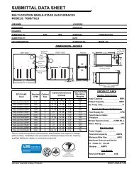
351579-YTS-B-0608thermostat. If a thermostat is installed on the system, theseinputs are connected <strong>to</strong> the thermostat interface board just asare the cooling/heating calls. These inputs are connectedthrough the Tstat Interface board directly <strong>to</strong> the respectivebinary inputs of the Controller. These signals are, however,each loaded with a resis<strong>to</strong>r <strong>to</strong> maintain voltage levels and <strong>to</strong>prevent “floating” of signals. Thermostat wiring is typically notshielded and may have induced voltages that could causeerrant signal readings by the controller.FILT - Dirty Filter switch [cus<strong>to</strong>mer supplied, field installed onfac<strong>to</strong>ry-provided harness connections] input <strong>to</strong> provide a filterstatus <strong>to</strong> the control. The control will alarm only after 24V hasbeen sensed for ten minutes.GV1-3 - Moni<strong>to</strong>ring that voltage is being supplied <strong>to</strong> gas valveson optional heat stages.LIM1-3 - Overtemperature inputs from optional heat stages.FSI - Freeze Stat is a cus<strong>to</strong>mer installed temperature switch onthe FSI input <strong>to</strong> the controller <strong>to</strong> tell the control that atemperature has occurred that risks the hot water or steam coil.Y1-4, W1-3 - If a thermostat is installed on the system, theseinputs will take priority over software programmed setpoints andlimits.SD - This terminal set allows attachment of an externalshutdown NC contact. 24VAC power is supplied <strong>to</strong> the board atSD2; a fac<strong>to</strong>ry installed jumper passes that power <strong>to</strong> terminal R<strong>to</strong> power the Simplicity Elite board. If an external shutdownsignal is required at a particular installation, remove the jumperand connect the NC shutdown circuit between SD1 and R.position of the guide vane. If the unit has a fac<strong>to</strong>ry-installedVariable Frequency Drive, the 2 <strong>to</strong> 10 VDC signal is wired fromVFD+/- output directly <strong>to</strong> the VFD’s signal input terminals <strong>to</strong>control fan mo<strong>to</strong>r speed.Table 2: Input Signal <strong>to</strong> Y1 Actua<strong>to</strong>r PositionInput Signal <strong>to</strong> Y1Actua<strong>to</strong>r Position10 VDC 90 degrees9 788 677 566 455 334 223 112 00 -58VDC over a 90 degree Span = 11.25 degrees/VDCFRVFDSimplicity12FanVFD +VFD -P13-1P14-1P14-2FRWhtBlkTB2185355OUTPUTSAnalog Outputs (AO) - Analog outputs provide a 2-10 VDCsignal <strong>to</strong> operate controlled devices. The Simplicity ® is currentlyconfigured <strong>to</strong> use only 2-10 VDC outputs <strong>to</strong> the VariableFrequency Drive, Inlet Guide Vane, Economizer Damper,Power Exhaust Dampers or VFD, and Heating water valves.Since these outputs are <strong>analog</strong>, they are continuous between 2and 10 Volts and are proportional <strong>to</strong> the 0 <strong>to</strong> 100% driveposition of the device.ECO - Economizer Actua<strong>to</strong>r - The modulating Economizer usesa Johnson Controls M9220GGAYK30 spring-return actua<strong>to</strong>r(PN: 025-30869-000A). This actua<strong>to</strong>r uses a 2-10 VDC signal<strong>to</strong> drive the dampers open. The actua<strong>to</strong>r drives 95 degreerotation. Note the chart below for a correlation between theinput drive signal at terminal 3 (Y1) of the actua<strong>to</strong>r and thecorresponding output drive position of the damper:VFD - Inlet Guide Vane or VFD - The Inlet Guide Vane uses aJohnson Controls M9220GGAYK30 spring-return actua<strong>to</strong>r. Thisactua<strong>to</strong>r uses the 2-10 VDC signal from VFD+/- terminals <strong>to</strong>drive the dampers open. The actua<strong>to</strong>r drives 95 degree rotation.Note the chart below for a correlation between the input drivesignal at terminal 3 (Y1) and the corresponding output driveFigure 4: VFD Control WiringEXD - Power Exhaust Damper Vane or VFD - Power ExhaustDamper Actua<strong>to</strong>r is a Johnson Controls M9220GGAYK30. Ituses a full open/ Full Closed scheme and operates a 95 degreerotation. If VFD Power Exhaust is configured, the same signalcontrols the exhaust fan mo<strong>to</strong>r drive frequency.HWV - Heating Water Valve - Cus<strong>to</strong>mer supplied and installed,connect <strong>to</strong> fac<strong>to</strong>ry-provided harness.BINARY OUTPUTS (BO)FAN - Fan Start/S<strong>to</strong>p Relay, VFD “permission” relay FRH1-3 - HEAT STAGES 1 TO 3 [OPTIONAL]C1 through C4 - Cooling Stages 1 through 4CF1 & CF2 - Condenser Fan Banks 1 and 2X - Controller Alarm is field-wired from the thermostat interfaceboard <strong>to</strong> signify a controller alarm has occurred.8 Johnson Controls Unitary Products
351579-YTS-B-0608Table 3: Simplicity ® Control InputsName Range Resolution Precision DescriptionY1 18 - 30 VAC On - Off +/- .5 VAC Request for the first stage of Cooling (24 VAC sense) Tstat Screw TerminalY2 18 - 30 VAC On - Off +/- .5 VAC Request for the second stage of Cooling (24 VAC sense) Tstat Screw TerminalY3 18 - 30 VAC On - Off +/- .5 VAC Request for the third stage of Cooling (24 VAC sense) Tstat Screw TerminalY4 18 - 30 VAC On - Off +/- .5 VAC Request for the fourth stage of Cooling (24 VAC sense) Tstat Screw TerminalW1 18 - 30 VAC On - Off +/- .5 VAC Request for the first Stage of Heating (24 VAC sense) Tstat Screw TerminalW2 18 - 30 VAC On - Off +/- .5 VAC Request for the second Stage of Heating (24 VAC sense) Tstat Screw TerminalW3 18 - 30 VAC On - Off +/- .5 VAC Request for the third Stage of Heating (24 VAC sense) Tstat Screw TerminalG 18 - 30 VAC On - Off +/- .5 VAC Request for the Fan (24 VAC sense) Tstat Screw TerminalR 18 - 30 VAC - -These terminals are a ¼' Female Fas<strong>to</strong>n and a Thermostat Screw terminalconnected <strong>to</strong> the power supply of the board.C Earth Ground - - These terminals are a ¼' Fas<strong>to</strong>n and a Thermostat Screw terminal.OCC 18 - 30 VAC On - Off +/- .5 VAC Occupied input (24 VAC sense) Tstat Screw TerminalSD 18 - 30 VAC - +/- .5 VAC Shut Down input Tstat Screw TerminalPurge 18 - 30 VAC On - Off +/- .5 VAC Building Purge input (24 VAC sense) Tstat Screw TerminalBAS Economizer 2 - 10 VDC Not Read by micro - Input that routes <strong>to</strong> the Economizer output Two Tstat Screw Terminals +&-HPS1 18 - 30 VAC On - Off +/- .5 VAC High Pressure Switch for Circuit # 1 (24 VAC sense)HPS2 18 - 30 VAC On - Off +/- .5 VAC High Pressure Switch for Circuit # 2 (24 VAC sense)HPS3 18 - 30 VAC On - Off +/- .5 VAC High Pressure Switch for Circuit # 3 (24 VAC sense)HPS4 18 - 30 VAC On - Off +/- .5 VAC High Pressure Switch for Circuit # 4 (24 VAC sense)LPS1 18 - 30 VAC On - Off +/- .5 VAC Low Pressure Switch for Circuit # 1 (24 VAC sense)LPS2 18 - 30 VAC On - Off +/- .5 VAC Low Pressure Switch for Circuit # 2 (24 VAC sense)LPS3 18 - 30 VAC On - Off +/- .5 VAC Low Pressure Switch for Circuit # 3 (24 VAC sense)LPS4 18 - 30 VAC On - Off +/- .5 VAC Low Pressure Switch for Circuit # 4 (24 VAC sense)Limit Switch 1 18 - 30 VAC On - Off +/- .5 VAC High Limit Switch input (24 VAC sense) For Burner section 1Limit Switch 2 18 - 30 VAC On - Off +/- .5 VAC High Limit Switch input (24 VAC sense) For Burner section 2Limit Switch 3 18 - 30 VAC On - Off +/- .5 VAC High Limit Switch input (24 VAC sense) For Burner section 3GV1 18 - 30 VAC On - Off +/- .5 VAC Gas Valve input (24 VAC sense) For Burner section 1GV2 18 - 30 VAC On - Off +/- .5 VAC Gas Valve input (24 VAC sense) For Burner section 2GV3 18 - 30 VAC On - Off +/- .5 VAC Gas Valve input (24 VAC sense) For Burner section 3Test / Reset / Up ON - Off ON - Off - Test / Reset But<strong>to</strong>n and Increment Data InputAddress / Down ON - Off ON - Off - Address But<strong>to</strong>n and Decrement Data InputAlarms / Advance Data ON - Off ON - Off - Alarm But<strong>to</strong>n and Advance Data InputProgram ON - Off ON - Off - Program But<strong>to</strong>n InputReal Time ClockWater Coil Freeze Stat(FSI)Supply Air Temp Sensor(SAT)Outside Air Temp Sensor(OAT)Space Temp Sensor(ST)Return Air Temp Sensor(RAT)Space Setpoint Offset(SSA)Building PressureSensor(BPS)Duct Pressure Sensor(DPS)24 hours, 365 Daysincluding Leap yearand DaylightSavings TimeSeconds - Real Time Clock Chip18 - 30 VAC On - Off +/- .5 VAC Hot Water Freeze Stat (24 VAC sense) two ¼ Fas<strong>to</strong>ns-40° - +180° F .1° F-40° - +180° F .1° F-40° - 180 °F+/- 2 °F acrossrange-40° - 180 °F+/- 2 °F acrossrangeThis is a 10KΩ type 3 Thermis<strong>to</strong>rThis is a 10KΩ type 3 Thermis<strong>to</strong>r32° - 100° F .1° F .5° F This is a 10KΩ type 3 Thermis<strong>to</strong>r-40° - +180° F .1° F-40° - 180 °F+/- 2 °F acrossrange0 - 20 KΩ 1 KΩ + and - 250 Ω0 - 5 VDC-.25 - +.25"WC.001 "WC0 - 5 VDC0 - 5 "WC .01 "WC.005 "WC1% Across range.05 "WC 1%across rangeThis is a 10KΩ type 3 Thermis<strong>to</strong>r3 position Mini Screw Terminal shared with Space Temp The common terminalin the center is common for both the Space Temp and Setpoint Offset.0 - 5 volt input0 - 5 volt inputAPS (APS) 18 - 30 VAC On - Off +/- .5 VAC Air Proving Switch (24 VAC sense)Fan Overload (FOVR) 18 - 30 VAC On - Off +/- .5 VAC Fan Overload Switch (24 VAC sense)CV / VAV Input 0 - 20 KΩ 1Ω + / - 5 Ω Resistive Input 0 - 5.5K = CV 10K - 20K = VAVJohnson Controls Unitary Products 9
351579-YTS-B-0608Table 3: Simplicity ® Control Inputs (Continued)Name Range Resolution Precision DescriptionDemand VentilationInput0 - 10 VDC0 - 2000 PPMof CO21 PPM20 PPM1% Across Range0 - 10 volt inputRemote Control 0 - 10 VDC .05 VDC 0.01 0 - 10 VDC Screw terminal two position Small screw terminalDirty Filter Switch(FILT)18 - 30 VAC On - Off +/- .5 VAC This is the Dirty Filter Switch (24 VAC sense)Low Voltage Detection 12 - 35 VAC .1 VAC .5 VAC This input moni<strong>to</strong>rs the 24 VAC for Low Voltage DetectionReturn Air Humidity(RAH)Outside Air Humidity(OAH)Comm Port0 - 5 VDC0 - 100%RH0 - 5 VDC0 - 100%RH128 nodes.05 VDC1% RH.05 VDC1% RHSeeCommunications.1 VDC2% Across Range.1 VDC2% Across RangeScaleable 0 - 10 volts Screw terminal two position Small screw terminalScaleable 0 - 10 volts Screw terminal two position Small screw terminal- Asynchronous Serial Port (RS485) three position Small screw terminal24 VAC - Class 1 18 - 30 VAC - - ¼'' quick connect for power <strong>to</strong> the contac<strong>to</strong>rs through the Relays.Table 4: Simplicity ® Control OutputsName Range Resolution Precision DescriptionLED On - Off - - Status LEDDisplayH1H2H3C1C2C3C4CF1CF2Fan7 segment W/Decimal PointClass 1 RelayContactsClass 1 RelayContactsClass 1 RelayContactsClass 1 RelayContactsClass 1 RelayContactsClass 1 RelayContactsClass 1 RelayContactsClass 1 RelayContactsClass 1 RelayContactsClass 1 RelayContacts6 "Seven Segment LED /W decimal point"- - Heat 1 contac<strong>to</strong>r output (Relay Contacts - 24 VAC/120 VAC)- - Heat 2 contac<strong>to</strong>r output (Relay Contacts - 24 VAC/120 VAC)- - Heat 3 contac<strong>to</strong>r output (Relay Contacts - 24 VAC/120 VAC)- -- -- -- -Compressor number one contac<strong>to</strong>r output(Relay Contacts - 24 VAC/120 VAC)Compressor number two contac<strong>to</strong>r output(Relay Contacts - 24 VAC/120 VAC)Compressor number three contac<strong>to</strong>r output(Relay Contacts - 24 VAC/120 VAC)Compressor number four contac<strong>to</strong>r output(Relay Contacts - 24 VAC/120 VAC)- - Condenser Fan contac<strong>to</strong>r output (Relay Contacts - 24 VAC/120 VAC)- - Condenser Fan contac<strong>to</strong>r output (Relay Contacts - 24 VAC/120 VAC)- - Fan contac<strong>to</strong>r output (Relay Contacts - 24 VAC/120 VAC)Exhaust Fan (EXH)Class 1 RelayContacts- - Exhaust Fan contac<strong>to</strong>r output (Relay Contacts - 24 VAC/120 VAC)Supply Fan VFD 2 - 10 VDC - - This is a 2 - 10 volt output capable of 10 maExhaust Fan Damper(EXD)2 - 10 VDC .1 VDC .1 VDC This is a 2 - 10 volt output capable of 10 maHot Water Valve(HWV)2 - 10 VDC .1 VDC .1 VDC This is a 2 - 10 volt output capable of 10 maHot Gas Reheat 2 - 10 VDC .1 VDC .1 VDC This is a 2 - 10 volt output capable of 10 maEconomizer (ECO) 2 - 10 VDC .1 VDC .1 VDC This is a 2 - 10 volt output capable of 10 maX 24VDC - - This is a 24VDC output for Alarms10 Johnson Controls Unitary Products
351579-YTS-B-0608SIMPLICITY ® PROGRAMMING OPTIONSThe paragraphs below provide a definition of, and specify thefunction related <strong>to</strong>, each of the parameters that are fieldadjustableusing the interfaces available. The Millennium ® Unitis shipped from the fac<strong>to</strong>ry with the necessary options preprogrammedas indicated by the model nomenclature. It isalways a good practice, though, <strong>to</strong> verify that the correctparameters are properly configured for the unit you arecommissioning. You can find a complete list of field-adjustableparameters in the “Settable System Parameters”.For a description of the parameters, see the Settable SystemParameters below and Table 5.INTERACTING THROUGH THE MILLENNIUM ®SIMPLICITY ®SET THE CLOCK• Power up the unit.• Press the Program but<strong>to</strong>n [upper left].• Press the Test/Up but<strong>to</strong>n [upper right]. Hold it in and it willstep through the parameters, or push in <strong>to</strong> advance oneparameter at a time. Advance <strong>to</strong> parameter 63, Hours.• Press Change [lower left] Press Up [upper right] or Down[lower right] <strong>to</strong> the correct hour [24 hour time].• Press Change <strong>to</strong> enter the new value.• Press Up <strong>to</strong> get <strong>to</strong> parameter 64, Minutes.• Press Change.• Press Up or Down <strong>to</strong> get <strong>to</strong> the correct minute value. PressChange <strong>to</strong> enter the new value.• If you are done changing parameters, press Program <strong>to</strong>exit the program mode.PARAMETER SETTINGThe but<strong>to</strong>ns allow the opera<strong>to</strong>r <strong>to</strong> go <strong>to</strong> a specific parameter and<strong>to</strong> view and change the data in that parameter.• To enter the parameter setting mode, press the Programbut<strong>to</strong>n. The control will display the current parameter numberin the two-digit display, and the present value of thatparameter in the four-digit display.• To change <strong>to</strong> another parameter, press the /Up or /Downbut<strong>to</strong>n <strong>to</strong> move <strong>to</strong> the address of the desired parameter.The present value of that parameter will display.• To change the data, press the /Change but<strong>to</strong>n. The valuewill flash. While it is flashing, press the /Up or /Down but<strong>to</strong>n<strong>to</strong> increase or decrease the value.• When the desired new value is showing, press the/Change Data but<strong>to</strong>n again <strong>to</strong> tell the control <strong>to</strong> s<strong>to</strong>re thenew value. You can verify that the new value is in placewhen the value s<strong>to</strong>ps flashing.• To exit Program mode, press the Program but<strong>to</strong>n again.INITIAL STARTUP OPTIONSCommissioning a new Millennium ® installation requires somefield adjustments <strong>to</strong> the Simplicity ® control program. Most ofthese adjustments simply involve setting up the varioussetpoints that are specific <strong>to</strong> your cus<strong>to</strong>mer’s needs (i.e.building pressure) or enabling some extended options that areintegrated in<strong>to</strong> the Simplicity control. Also, if there are fieldchanges, i.e. a modulating power exhaust option, the controlconfiguration will need <strong>to</strong> be modified for the new option.METRIC OPERATION (ENGLISH)The fac<strong>to</strong>ry default for this option is OFF. The metric (SI)conversions are part of the controller software; when the Metricparameter is selected, temperature setpoints and readings willconvert <strong>to</strong> Centigrade (°C).SETTABLE SYSTEM PARAMETERSThe following headings list each parameter’s name and itsdefault setting. The control is set at the fac<strong>to</strong>ry for the options ofthe specific unit; if a replacement control is being installed, theentire parameter set must be matched <strong>to</strong> the unit. The numberin (parentheses) is the value of a parameter in an un-configuredcontrol.Compressors - (2) - This tells the control the number ofcompressors available. The Fac<strong>to</strong>ry Default [the value in anunconfigured replacement control] is 2 and can be adjustedfrom 1 <strong>to</strong> 4.Heat Stages - (2) - This tells the control the number of heatingstages available. This parameter may be set from 0 <strong>to</strong> 3. Thedefault setting is 2 stages of heat. When modulating gas heat isinstalled the parameters is always set <strong>to</strong> 2.Hydronic Heat - (OFF) - This tells the control that a Hot Water Coilis installed. If the control is going <strong>to</strong> modulate the Hot Water Valveit will also turn on the Heat One output. This is <strong>to</strong> energize the VAVheat relay for the VAV boxes. The default is OFF for this option. Ifthis parameter is enabled, remember <strong>to</strong> set the Hydronic Heat Firstand Second Stage Setpoints and the Economizer LoadingSetpoint found in the ”Simplicity ® Setpoints”.Stage 1 Hydronic Heat SAT Setpoint - (120 °F) - When theHydronic Heat option is enabled, the control will maintain this SATsetpoint for a call for first stage Heating, by modulating the HotWater Valve. This is the reset temperature when operating a VAVunit in the Heating mode. The reset range for SAT setpoint is from80 °F <strong>to</strong> 180 °F with 120 °F shipped as the default.Hydronic Heat Reverse Actuated Valve - (OFF) - This settingis <strong>to</strong> allow convenient use of reverse acting water valves;setting this parameter <strong>to</strong> (ON) will change the signal <strong>to</strong> 2VDC =open, 10 VDC = closed.SAT Control for Cooling - (ON) - This tells the control if it isgoing <strong>to</strong> do excessive SAT moni<strong>to</strong>ring and tripping or not, forCooling. The SAT should be maintained in an acceptablerange in order <strong>to</strong> achieve reliable compressor operation. Thecompressor trip limits are user adjustable between 40 °F and65 °F in one degree increments. The default cooling triplimits are 50 °F for stages 2-4, and 45 °F for stage 1. Whenthe SAT drops below the trip limit for each respectivecompressor, that compressor is locked out and a 5 minuteASCD is initiated for that compressor. If this option isenabled, remember <strong>to</strong> set the compressor cooling limits forlow limit trip.Johnson Controls Unitary Products 11
351579-YTS-B-0608Power Exhaust - (ON) - This tells the control if it has the PowerExhaust option installed.Economizer Damper Position for Exhaust Fan <strong>to</strong> turn ON(Non-Modulating PE Only) - (60%) - This tells the control theEconomizer Damper position <strong>to</strong> turn on the Exhaust Fan. Thisvalue is based on the 0%-100% output drive signal from thecontroller <strong>to</strong> the economizer damper actua<strong>to</strong>r.Economizer Damper Position for Exhaust Fan <strong>to</strong> turn OFF(Non-Modulating PE only) - (20%) - This tells the control theEconomizer Damper position <strong>to</strong> turn off the Exhaust Fan. Thisvalue is based on the 0%-100% output drive signal from thecontroller <strong>to</strong> the economizer damper actua<strong>to</strong>r.Modulating Exhaust - (OFF) - This tells the control if thePower Exhaust is Modulating or not. A modulating exhaust willbe equipped with a Building Pressure Sensor [BPS]. A Non-Modulating exhaust will look <strong>to</strong> the economizer damper position<strong>to</strong> energize the EXD output. If the sensor gets disconnected, orfails, an alarm is set. The alarm can be turned off by correctingthe sensor problem (or; by turning off this option). The control isnot in this case self-configuring. It will not au<strong>to</strong>matically use theBuilding Pressure Sensor if the sensor is connected.Exhaust VFD Installed - (OFF) - If the unit has a VFD, the EXDoutput will be enabled when the supply fan is ON.Exhaust Damper Position For The Exhaust Fan To Turn On(Modulating Only) - (80%) - This tells the control the ExhaustDamper position at which <strong>to</strong> turn on the Exhaust Fan. Thisvalue is based on the 0%-100% output drive signal from thecontroller <strong>to</strong> the damper actua<strong>to</strong>r.Exhaust Damper Position For Exhaust Fan To Turn Off(Modulating Only) - (20%) - This tells the control the ExhaustDamper position <strong>to</strong> turn off the Exhaust Fan. This value isbased on the 0%-100% output drive signal from the controller <strong>to</strong>the damper actua<strong>to</strong>r.Building Pressure Setpoint - (+0.100”WG) - This is thepressure setpoint the control will maintain when operating aPower Exhaust. The Building Pressure Setpoint is adjustablefrom -0.200”WG <strong>to</strong> +0.200”WG. The fac<strong>to</strong>ry programmed defaultis +0.100”WC. This setpoint is used when the exhaust control isimplemented as Proportional Control (with a Modulating ExhaustAir Damper or VFD controlled from building static pressure), oras a Two-position Control using building static (Power ExhaustFan controlled on-off from building static pressure).Economizer - (ON) - This tells the control that there is anEconomizer Installed.Economizer Min Position - (20%) - This tells the control whatthe minimum outdoor damper position will be for the Occupiedmode. Adjustable from 0-100%, the Economizer MinimumPosition default is 20%.Economizer First Stage Setpoint - (55 °F) - This tells thecontrol what Supply Air Temperature <strong>to</strong> maintain for a call forfirst stage of cooling. This is used only during Constant Volumecooling mode with Economizer operation. The setpoint is set at55 °F with an adjustable range from 40 °F <strong>to</strong> 65 °F.Economizer Second Stage Setpoint - (50 °F) - This tells thecontrol what Supply Air Temperature <strong>to</strong> maintain for a call forsecond stage of cooling. This is used only during ConstantVolume cooling mode with Economizer operation. This setpointis set at 50 °F with a range from 40 °F <strong>to</strong> 65 °F.Outside Air Humidity (OAH) Sensor Enable - (OFF) - Thissetting tells the control that it is expected <strong>to</strong> use Outside AirEnthalpy (calculated from Outside Air Temperature and OutsideAir Relative Humidity sensed values) <strong>to</strong> decide if Outside Aircan be used for cooling.The control is self-configuring <strong>to</strong> the best available decisionstrategy for free cooling availability. For example, if it detectsthat OAT and OAH and RAT and RAH sensors are allconnected and reliable, will self-configure for DifferentialEnthalpy operation. If one of the return air sensors should fail,the control will reconfigure for Outside Enthalpy operation, etc.If the OAH Sensor Enable option is turned ON, it means that theOutside Enthalpy Operation, or better decision strategy, isexpected (and supported by installed sensors). If theappropriate sensors are not installed, or one of them failed, asensor failure alarm is set. The alarm can be turned off byturning off the OAH Sensor Enable option. Thus, the optionsetting is used <strong>to</strong> reflect the desired operation and mainly <strong>to</strong>control sensor failure alarms.The option setting can be viewed as specifying that (the selfconfiguredeconomizer decision strategy has <strong>to</strong> be at least this,or better, otherwise an alarm is set). If the option is OFF, thecontrol still may self configure <strong>to</strong> Outside Enthalpy Operation, oreven <strong>to</strong> Differential Enthalpy Operation (if all needed sensorsare available), but this option setting will allow also the decisionstrategy based on only OAT (in case other sensors fail, or arenot installed) without setting an alarm.Outside Air Enthalpy Setpoint - (27 BTU/LB) - This tells thecontrol an outside air enthalpy limit. Below this limit, outside airis available for cooling. See enthalpy chart. This parameteruses a one BTU/LB hysteresis on each side of the limit. Thelimit is preset <strong>to</strong> 27 BTU/ LB with an adjustable range from 10 <strong>to</strong>50 BTU/LB.Return Air Humidity (RAH) Sensor enable - (OFF) - This tellsthe control that it will compare Outside Air Enthalpy (calculatedfrom Outside Air Temperature and Outside Air RelativeHumidity sensed values) and Return Air Enthalpy (calculatedfrom Return Air Temperature and Return Air Relative Humiditysensed values). The control will use the air stream with thelower enthalpy for cooling.The control is self-configuring <strong>to</strong> the best available decisionstrategy for free cooling availability. For example, if it detects thatOAT and OAH and RAT and RAH sensors are all connected andreliable, will self-configure for Differential Enthalpy operation. Ifone of the return air sensors should fail, the control will s<strong>to</strong>p usingrules that involve RAH and set an alarm.If the RAH Sensor Enable option is turned ON (and supportedby installed sensors), Differential Enthalpy Operation can beenabled. If the appropriate sensors are not installed, or one ofthem failed, a sensor failure alarm is set. The RAH alarm can12 Johnson Controls Unitary Products
351579-YTS-B-0608be turned off by turning off the RAH Sensor Enable option.Thus, the option setting is used <strong>to</strong> reflect the desired operationand mainly <strong>to</strong> control sensor failure alarms.Economizer Loading <strong>to</strong> Control SAT - (ON) - This tells thecontrol if it is going <strong>to</strong> use Economizer Loading <strong>to</strong> controlexcessive SAT [supplying warmer outside air <strong>to</strong> keep SAT fromgoing <strong>to</strong>o low]. This parameter is only applicable outside thenormal Economizer operation. During the Economizeroperation, the loading function is always performed and is anintegral part of the control algorithm.Duct Static Setpoint - (1.5”WG) - This parameter is applicableonly <strong>to</strong> VAV mode of operation. This is the pressure setpoint thatthe control will maintain when operating the fan in a VAV unit.This setpoint is adjustable between 0”WG and 5”WG with thedefault set <strong>to</strong> 1.5”WG.Duct Static High Limit Setpoint - (4.5”WG) - This parameter isapplicable only <strong>to</strong> VAV mode of operation. This tells the control atwhat Static Pressure <strong>to</strong> shut down the unit due <strong>to</strong> a Fan controlfailure. This setpoint is <strong>to</strong> insure that we don't continue <strong>to</strong> operatethe Fan with an Inlet Guide Vane or VFD problem that couldcause the ductwork <strong>to</strong> fail from duct pressure. When the StaticPressure reaches this setpoint (4.5”WG default), the control willdrive the supply fan control output <strong>to</strong> zero. If the static pressuredoes decrease below the “Duct Static High Limit Setpoint” within3 seconds after decreasing the supply fan control output <strong>to</strong> zero,the control will resume normal operation. If there is no change instatic pressure after 3 seconds, the control will generate a HighDuct Static alarm, shut down all the outputs including the Fan andshut down the unit. The alarm is written <strong>to</strong> the Error His<strong>to</strong>ry Bufferand will trigger s<strong>to</strong>ring a snapshot of Points Screen data alongwith a date and time stamp. In networked applications, the alarmflag is readable by the network. This parameter can be adjustedfrom 0”WG <strong>to</strong> 5”WG with the fac<strong>to</strong>ry default set <strong>to</strong> 4.5”WG.The cus<strong>to</strong>mer must be aware of the duct pressure design limit,and what the duct pressure sensor will be reading when the peakpressure is reached [the pressure pickup tube may not havebeen located at the place of highest pressure in the system].The alarm must be reset (after the problem that caused thealarm is corrected) by resetting the controller by turning power<strong>to</strong> the unit off and back on, or by reset command issued by anexternal connection.Morning Warm Up - Is inferred from the entries inOccupied/UnoccupiedOccupied - (from settings in Weekly Schedule and HolidaySchedule Tables 11 and 12.) - See discussion in Sequence ofOperation.Unoccupied - (from settings in Weekly Schedule and HolidaySchedule Tables 11 and 12.) - See discussion in Sequence ofOperation.VAV High Temperature SAT Setpoint for Cooling - (60 °F) -The control will maintain this SAT when operating in VAV modewith a thermostat that is calling for first stage cooling. Thisparameter may be adjusted from 40 °F <strong>to</strong> 70 °F with 60 °F setas the default value.VAV Low Temperature SAT Setpoint for Cooling - (55 °F) -The control will maintain this SAT when operating in VAV modewith a thermostat that is calling for second stage cooling. Thisparameter may also be adjusted from 40 °F <strong>to</strong> 70 °F with 55 °Fset as the default value.VAV SAT Reset Setpoint - (72 °F) - This parameter is usedonly in VAV mode with a Space Sensor. The control will switchfrom the VAV Lower Cooling SAT Setpoint <strong>to</strong> the VAV UpperCooling SAT Setpoint when this Space Temperature Setpointminus 0.5 °F is reached. The control will switch from Highsetpoint back <strong>to</strong> Low setpoint when the space temperature gets2 °F above this setpoint. This is SAT reset based on SpaceTemperature. The reset occurs in both Occupied andUnoccupied modes and may be adjusted from 40 °F <strong>to</strong> 85 °F.The fac<strong>to</strong>ry default is 72 °F.VAV Occupied Heating - (OFF) - This option applies in VAVmode with a Space Sensor and does not affect VAV Occupiedheating if requested by a thermostat. When this option is<strong>to</strong>ggled on, a VAV unit is able <strong>to</strong> operate heating in the occupiedmode as long as it is operating with a Space Sensor. If theSpace Temperature drops <strong>to</strong> 2 °F below the VAV SAT ResetSetpoint the control will read the RAT. If the RAT is below theMorning Warm Up RAT Setpoint the unit will enter the OccupiedHeating mode. Operation is the same as Morning Warm Up.This parameter is fac<strong>to</strong>ry set <strong>to</strong> OFF.Comfort Ventilation Mode - (OFF) - Comfort Ventilation is aSAT control mode that controls SAT during “satisfied” periods ina fairly wide temperature band, using mostly Outside Air, andalso cooling and heating stages as necessary. It is availableonly on the Constant Volume unit.To enable Comfort Ventilation, the programmable parameter“Comfort Ventilation Mode” must be set <strong>to</strong> ON (default setting isOFF).For a detailed explanation of Comfort Ventilation, refer <strong>to</strong> theSequence of Operation in this manual.Comfort Ventilation High Supply Air Setpoint - (80 °F) - Thisis the High Limit Setpoint for the Comfort Ventilation mode. Fora stable operation of Comfort Ventilation function, the HighSupply Air Setpoint should be set 10.0 °F or more above theLow Setpoint.Comfort Ventilation Low Supply Air Setpoint - (70 °F) - Thisis the Low Limit Setpoint for the Comfort Ventilation mode. Fora stable operation of Comfort Ventilation function, the LowSupply Air Setpoint should be set 10.0 °F or more below theHigh Setpoint.Dirty Filter Switch - (OFF) - This tells the control that a DirtyFilter Switch is connected <strong>to</strong> it. The control will wait for tenminutes after the switch has closed before declaring a DirtyFilter Alarm. The alarm is written <strong>to</strong> the Error His<strong>to</strong>ry Buffer. Innetworked applications, the error flag is readable by thenetwork. The alarm will au<strong>to</strong>matically reset when the errorcondition is corrected.The default is OFF.Johnson Controls Unitary Products 13
351579-YTS-B-0608Heating Lockout on OAT - (75 °F) - This is the Outside AirTemperature Setpoint that the control will use <strong>to</strong> lock out Heatingwhen the OAT is above this setpoint. There is a one-degreehysteresis on each side of the setpoint. This parameter isadjustable between 0 °F and 100 °F with the default set <strong>to</strong> 75 °F.Heating Lockout on OAT affects only staged heating, it does notaffect hydronic heat. If the heating is energized when OATreaches this setpoint, the Status LED will indicate the lockoutcondition immediately, but the control will finish the heatingmode and then lock out the heating.Note that a Heating Lockout on OAT may occur while thecontrol is in a heating mode and there is a demand for heating.If the OAT then decreases below the lockout setting while thecall for several heat stages exists, the heat stages will turn onsimultaneously. This is considered acceptable as this situationis not expected <strong>to</strong> occur frequently.Cooling Lockout on OAT - (45 °F) - This is the Outside AirTemperature Setpoint that the control uses <strong>to</strong> lock out Coolingwhen the OAT is below this setpoint. Adjustable from 0 °F <strong>to</strong>100 °F, the default is 45 °F.Unoccupied Heating Setpoint - (60 °F) - This value is theUnoccupied Heating Setpoint. It is used in both CV and VAVmode of operation (in VAV, it controls Unoccupied heating witha Space Sensor).UnOcc.Htg.Occ.Htg.UnOcc.Clg.Figure 5: Sequence Of Setting The Set PointsOcc.Clg.The control will attempt <strong>to</strong> correct wrong temperature overlapsettings; for example, if a change is made that would putOccupied Heating above Occupied Cooling, the OccupiedCooling setting will change <strong>to</strong> stay above the heating setpoint.Occupied Heating Setpoint - (68 °F) - This value is theOccupied Heating Setpoint. It is used only in CV mode ofoperation. Its relationship <strong>to</strong> the related setpoints is as definedin the Unoccupied Heating Setpoint paragraph above.Unoccupied Cooling Setpoint - (85 °F) - This value is theUnoccupied Cooling Setpoint. It is used in both CV and VAVmode of operation (in VAV, it controls Unoccupied cooling with aSpace Sensor).Occupied Cooling Setpoint - (72 °F) - This value is theOccupied Cooling Setpoint. It is used only in CV mode ofoperation. Its relationship <strong>to</strong> the related setpoints is as definedin the Unoccupied Heating Setpoint paragraph above.[Input] FSI (Hot Water Freeze Protection) - (OFF) - Thisoption is used only on roof<strong>to</strong>p units with hydronic heat(Hydronic Heat Option is turned ON). Freeze protection shouldalways be placed on units that use hydronic heating. When thecontrol senses 24VAC, the control will turn on the Hot Watervalve <strong>to</strong> 100%. The control will continue <strong>to</strong> drive the valve at100% until five minutes after the switch has opened. Then thevalve will revert <strong>to</strong> normal operation. If the control is operatingthe Fan, it will close the Economizer fully until the freezecondition is over. If the fan is off and the RAT drops below 40 °F,the Hot Water Valve will turn on 100%.Supply AirTemp (SAT) Alarm Setpoint for Cooling - (0 °F) - Ifthe SAT does not drive below this setpoint when all stages ofcompression are operating and 10 minutes has elapsed sincethe last compressor was energized, the control will declare aCooling SAT Failure Alarm.The alarm is written <strong>to</strong> the Error His<strong>to</strong>ry Buffer. In networkedapplications, the alarm flag is readable by the network.The alarm will reset au<strong>to</strong>matically if the SAT does decreasebelow the setpoint (the alarm condition no longer exists), orwhen a compressor is turned off (the control does not requestall compressors operate). The SAT Alarm Setpoint for Coolingcan be adjusted from 50 °F - 80 °F. If the value is set <strong>to</strong> 0 °F(default) this feature is disabled.Before the control declares an error, it will read the OAT and theEconomizer position. If the OAT is more than 20 °F warmer thanthe setpoint and the Economizer is open more than 20%, thecontrol will close the Economizer for 10 minutes and then readthe SAT. If the SAT falls below the setpoint, the control willdeclare an Economizer Minimum Position alarm. The controlwill keep the Economizer closed and finish the Cooling mode.After the Cooling mode has been satisfied, the control will movethe Economizer back <strong>to</strong> the minimum position.Supply Air Temp (SAT) Alarm Setpoint for Heating - (0 °F) -The SAT must drive above this setpoint when all stages of heatingare operating and 10 minutes has elapsed since the last stage wasenergized. If this does not happen, the control will declare aHeating SAT Failure Alarm. The alarm is written <strong>to</strong> the ErrorHis<strong>to</strong>ry Buffer. In networked applications, the alarm flag is readableby the network. The alarm will reset au<strong>to</strong>matically if the SAT doesincrease above the setpoint (the alarm condition no longer exists),or when a heating stage is turned off (the control does not requestall heat stages <strong>to</strong> operate).The SAT Alarm Setpoint for Cooling can be adjusted from 70 °F -120 °F. If the value is set <strong>to</strong> 0 °F (default) this feature is disabled.Before the control declares an error, it will read the OAT and theEconomizer position. If the OAT is more than 20 °F colder thanthe setpoint and the Economizer is open more than 20%, thecontrol will close the Economizer for 10 minutes and then readthe SAT. If the SAT rises above the setpoint, the control willdeclare an Economizer Minimum Position alarm. The controlwill keep the Economizer closed and finish the Heating mode.After the Heating mode has been satisfied, the control will movethe Economizer back <strong>to</strong> the minimum position.Unoccupied Override Time Period - (60 min) - TheUnoccupied Override Time Limit function will determine howlong the unit will operate in the Unoccupied Override modewhen the Override but<strong>to</strong>n is pressed on the Space Sensor.14 Johnson Controls Unitary Products
351579-YTS-B-0608Once the Unoccupied Override mode is initiated, it will continueuntil the programmed Unoccupied Override Time Limit isreached. The Override mode can not be cancelled by, forexample, a change of state of the Occupied input <strong>to</strong> ON(occupied) and then back <strong>to</strong> OFF (unoccupied).This parameter is adjustable from 0 <strong>to</strong> 240 minutes. The defaultis 60 minutes.Fan Delays (ON) & (OFF) - Any time the control starts acompressor it will load the Fan On Delay for Cool with theprogrammed value. Any time the control turns off all thecompressors it will load the Fan Off Delay for Cool with theprogrammed value.When the control turns on a gas heat stage, it will beginmoni<strong>to</strong>ring the gas valve and load the Fan On Delay For Heatwith the programmed value when it senses gas valve voltage. Ifmodulating gas heat is installed, then Fan Off Delay in heatingmust be set <strong>to</strong> Off.When the thermostat terminates the call for W1 the control willturn off H1 output and load the Fan Off Delay for Heat with theprogrammed value.After the control has turned on heat, it will start moni<strong>to</strong>ring theGas Valve. If at any time the Gas Valve (24 VAC) is not presentfor five minutes while H1 is on, the control will flag an Alarm.Anytime GV1/H1 goes off during the fan on delay, the controlwill force the fan on, for the fan off delay period. The control willwait for GV1 <strong>to</strong> be on at least 15 seconds before forcing the fanon. If GV1 has been on for at least 15 seconds, and then goesaway before the Fan On Delay has finished, the fan will turn onanyway far a length of time equal <strong>to</strong> the Fan Off Delay period.If the control senses this input along with a Y signal, it will notturn on the compressors and it will run the Heating mode.Heating takes priority.Fan ON Mode with the Sensor Option - (ON) - When thisoption is turned ON, the supply fan will continue running whenthe zone sensor based temperature control is satisfied. Thisoption applies only in systems using a zone sensor and only inOccupied mode. With this option turned OFF, or in Unoccupiedmode, the fan will go off when the zone sensor basedtemperature control is satisfied and will go on only when there isa call for heating or cooling. Turning this option ON is anequivalent of selecting fan ON (rather than AUTO) in systemswith a thermostat. In a thermostat system, the fan control followsthe thermostat's G signal. In sensor systems and in the Occupiedmode, the fan control follows the Fan ON Mode option.Space Sensor Enable - (OFF) (INTERNALLY SET) - Thecontrol will use this input if it detects the device.RAT Sensor Enable - (OFF) (INTERNALLY SET) - The controlwill use this input if it detects the device.Demand Ventilation (ON) - Setting this parameter on tells thecontrol <strong>to</strong> expect a signal from a 0-10VDC CO 2 sensor. Thedefault setting for CO 2 is 1,000 ppm.Demand Ventilation Setpoint - (1000 ppm) - This Setpoint isthe maximum Indoor Air Quality (IAQ) level that the control willallow. It is adjustable from 700 ppm <strong>to</strong> 1500 ppm.IAQ Sensor Range - (5,000 ppm) - This tells the control whatthe full range is for a specific IAQ sensor. It can be changedfrom 0 <strong>to</strong> 10,000 ppm.Cooling Mode Enable (ON) - This tells the control if it hasCooling Available (Mode Switch). If this option is turned off,cooling operation is disabled. Note that this parameter does notaffect cooling operation in Comfort Ventilation mode.Heating Mode Enable - (ON) - This tells the control if it hasHeating Available (Mode Switch). If this option is turned off,heating operation is disabled. Note that this parameter does notaffect heating operation in Comfort Ventilation mode.Space Setpoint Offset - (3 °F) - The Space Setpoint Offset isthe +/- value the control will use <strong>to</strong> offset the Space Setpointwhen the slidebar Space Sensor is used. For example, if theSpace Setpoint Offset value is set <strong>to</strong> 3.0 °F, shifting the slidebarall the way in minus direction will decrease the Space Setpointby 3.0 °F and shifting it all the way in plus direction will increasethe Space Setpoint by 3.0 °F. It is adjustable from 0 °F <strong>to</strong> 5 °F.ASCD Override - This is not an option parameter but rather aone-time command issued by pressing the Test / Reset / Upbut<strong>to</strong>n pressed and released within five seconds; the ASCD’swill be set <strong>to</strong> zero for one cycle.Run Test (Commissioning Test) - This is not an optionparameter but rather a one-time command, activated by settingparameter 1 ON.When the Run Test command is issued, the control will shut theunit down if it is running and then start a Run test sequence:1. Turn on the Fan and then turn on all the compressors, oneat a time, with a 15-second delay between them. Condenserfan #1 turns on with compressor #1, condenser fan#2 turns on with compressor #2. After the last compressorhas been turned on, the control will run the compressorsfor the programmed minimum run time and then turn themall off. Condenser fans are also turned off.2. The control will then turn on the Heat stages, one at a time,with a 15 second delay between them. The control will runeach Heat stage for three minutes and then turn all theHeat off.3. The control will then open the Economizer <strong>to</strong> the 100%open position and wait five minutes before closing it <strong>to</strong> theMinimum Position. When the economizer is at 100%, theexhaust damper will be open <strong>to</strong> 100% and the exhaust fanruns for 5 minutes, then shuts down.4. During this Run Test operation the control will read all theinstalled sensors and verify that their readings are good. Ifany error is detected the control will display the appropriateerror. During the Run Test, the supply fan continues <strong>to</strong> bemoni<strong>to</strong>red via the Air Proving Switch, and a fan failure willcause a unit shutdown.After the control is finished with the Run Test the normaloperation will resume. This command is a good method <strong>to</strong> use<strong>to</strong> ensure the control is operating and all input and output pointsare functional.Johnson Controls Unitary Products 15
351579-YTS-B-0608Table 5: Settable System ParametersAddress Function Unit Range Default Your Settings1 Run test ON-OFF OFF2 Fan on delay-Heating Sec 0-30 303 Fan off delay-Heating Sec 0-255 604 Fan on delay-Cooling Sec 0-30 05 Fan off delay-Cooling Sec 0-255 306 Fac<strong>to</strong>ry setting - - 1 Do not change7 Suspend Cont Fan when starting Heating ON-OFF OFF8 Construction Mode - ON-OFF OFF9 Unoccupied Override Time Period Minutes 0-240 6010 Occupied Cooling Setpoint °F 45-99 7211 Occupied Heating Setpoint °F 45-99 6812 Unoccupied Cooling Setpoint °F 45-99 8513 Unoccupied Heating Setpoint °F 45-99 6014 SAT Control-Cooling ON-OFF ON-OFF ON15 Cooling SAT Control Setpoint °F 40-65 5016 SAT Control for Heating ON-OFF ON-OFF ON17 Heating SAT Control Setpoint °F 100-180 13518 Hydronic Heating ON-OFF ON-OFF OFF19 First Stage Hydronic Heating SAT Setpoint °F 80-180 12020 Second Stage Hydronic Heating SAT Setpoint °F 80-180 15021 Hydronic Heating Reverse Actuated Valve ON-OFF ON-OFF OFF22 Remote Control ON-OFF ON-OFF OFF23 VAV Upper Cooling SAT °F 40-70 6024 VAV Lower Cooling SAT °F 40-70 5525 VAV SAT Reset Setpoint °F 40-85 7226 VAV Occupied Setpoint ON-OFF ON-OFF OFF27 VAV Occupied Heating Setpoint °F 40-85 6828 Morning Warm-Up ON-OFF ON-OFF ON29 Morning Warm-Up RAT °F 50-85 7030 Duct Static Setpoint " H2O 0 – 5” 1.5”31 Building Pressure Setpoint " H2O neg .25 <strong>to</strong> .25 .1”32 Economizer ON-OFF ON-OFF ON33 Economizer First Stage °F 40-65 5534 Economizer Second Stage °F 40-65 5035 Economizer Minimum Position Percent 0 <strong>to</strong> 100% 2036 Outside Air Humidity Sensor ON-OFF ON-OFF OFF37 Economizer Outside Air Enthalpy Setpoint BTUs Per Pound 10-50 2738 Return Air Humidity Sensor ON-OFF ON-OFF OFF39 Economizer OAT Enable °F 40-80 5540 Demand Ventilation ON-OFF ON-OFF OFF41 IAQ Sensor Range PPM 0-5000 200042 Demand Ventilation Setpoint PPM 0-5000 100043 Power Exhaust ON-OFF ON-OFF ON44 Modulating Exhaust ON-OFF ON-OFF OFF45 Exhaust VFD Installed ON-OFF ON-OFF OFF46Exhaust Damper Position for Exhaust Fan <strong>to</strong>Turn On (Modulating Only)% Of Damper Position 0-100 80%16 Johnson Controls Unitary Products
351579-YTS-B-0608Table 5: Settable System Parameters (Continued)Address Function Unit Range Default Your Settings474849Exhaust Damper Position for Exhaust Fan <strong>to</strong>Turn Off (Modulating Only)Economizer Damper Position for Exhaust Fan<strong>to</strong> Turn On (Non-Modulating Only)Economizer Damper Position for Exhaust Fan<strong>to</strong> Turn Off (Non-Modulating Only)% Of Damper Position 0-100 20%% Of Damper Position 0-100 60%Percent of EconomizerPosition0-100% 20%50 APS Data Open-Closed Open-Closed Open51 Dirty Filter Switch ON-OFF ON-OFF OFF52 Dirty Filter Switch Data Open-Closed Open-Closed Open53 Cooling Mode Enable ON-OFF ON-OFF ON54 Heating Mode Enable ON-OFF ON-OFF ON55 Fan On Mode with the Sensor Option ON-OFF ON-OFF ON56 Space Setpoint Offset °F -5 <strong>to</strong> 5 0 degrees57 Metric Operation ON-OFF ON-OFF OFF58 BAS Economizer ON-OFF ON-OFF OFF59 Year Year 00-99 460 Month Month Number 161 Day of Month Day Number 162 Day of Week Day Number 163 Hour Hour 0-23 064 Minute Minutes 0-59 065 SAT (Supply Air Temp) °F -40 <strong>to</strong> 180 Read Only Read Only66 RAT (Return Air Temp) °F -40 <strong>to</strong> 180 Read Only Read Only67 OAT (Outside Air Temp) °F -40 <strong>to</strong> 180 Read Only Read Only68 ST (Space Temp) °F -40 <strong>to</strong> 180 Read Only Read Only69 OAH (Outside Air Hum) %RH 0 <strong>to</strong> 100% Read Only Read Only70 RAH (Return Air Hum) %RH 0 <strong>to</strong> 100% Read Only Read Only71 Occupied Input Enable ON-OFF ON-OFF OFF72 Alarm ArrayRead OnlyRead Only73 Alarm Array Read Only Read Only74 Alarm ArrayThese values represent the last 5 alarm codes inmemory. 72 is latest & 76 oldest.Read Only Read Only75 Alarm Array Read Only Read Only76 Alarm Array Read Only Read Only77 CV/VAV Mode Read Only Flag CV=0 VAV=1 Read Only Read Only78 Hot Gas Reheat ON-OFF ON-OFF OFF79 Hot Gas Bypass ON-OFF ON-OFF OFF80 Compressors Number 2 <strong>to</strong> 4 Fac<strong>to</strong>ry Set81 Heat Stages Number 0 <strong>to</strong> 3 Fac<strong>to</strong>ry Set82 Duct Static Reading Inches Water 0 <strong>to</strong> 5.0” Read Only83 Building Pressure Reading Inches Water 0 <strong>to</strong> 5.0” Read Only84 Low Ambient Kit Installed ON-OFF ON-OFF Fac<strong>to</strong>ry Set85 Building Static Pressure Sensor Enable ON-OFF ON-OFF Fac<strong>to</strong>ry Set86 ERV Installed ON-OFF ON-OFF Fac<strong>to</strong>ry Set87 ERV Unoccupied Fan ON-OFF ON-OFF Fac<strong>to</strong>ry Set88 Duct Static Shutdown Setpoint Inches Water 0 <strong>to</strong> 5.0” 4.5”NOTES:For On/Off functions, 1 is ON and 0 is OFFRead only items are readings from sensors which only change as the measured condition changes.Johnson Controls Unitary Products 17
351579-YTS-B-0608MILLENNIUM ® SEQUENCE OF OPERATIONOVERVIEWThe Millennium ® Simplicity ® control has comprehensive rulesets <strong>to</strong> respond <strong>to</strong> heat and cool calls, provide anti-shortcycleand other safeties, date / time clock, and other features makingthe programmable thermostat unnecessary. The Millennium ®Simplicity ® extends on the rules of the Synthesys <strong>digital</strong> control.With an attached (optional) Room Sensor, the control providescalls for heating and cooling and occupied override. The controldetermines when <strong>to</strong> start morning warm-up, mechanicalcooling, or heat based on parameter settings in the Millennium ®Simplicity ® control, its internal time clock, Occupied and holidayschedules, the deviation from the setpoints, and the rate oftemperature change.A separate thermostat cannot determine if an output function isavailable. For example, if the belts on the supply fan were <strong>to</strong>break, the thermostat would still call for the fan <strong>to</strong> operate and,if space conditions require, call for heating or cooling. Logic inthe control prevents undesired operation of heating and coolingstages, with interlocks and minimum run times. Moreover, thecontrol can report faults on its <strong>digital</strong> display or on a network <strong>to</strong>a moni<strong>to</strong>ring system.Control logic is designed such that airflow must be proven beforeany heating or cooling stage can operate. Mechanical cooling islocked out below 40 °F outdoor ambient for all units without headpressure control. The control provides voltage <strong>to</strong> energize thecontac<strong>to</strong>rs for the supply fan, cooling stages, heating stages, andoptions such as the economizer and power exhaust. Thethermostat makes calls for cooling and heating; the Simplicity ®control is responsible for executing the rules putting these calls in<strong>to</strong>action and protecting the unit through appropriate safety devices. Ifthe Millennium ® Simplicity ® senses low voltage, it will hold anycall that energizes a contac<strong>to</strong>r until the voltage is adequate. It willnot alarm for low voltage, but will provide a flash code.The control also energizes the supply fan and cooling stagesbased on external inputs from the thermostat:• G - Supply Fan• Y1-1st Stage Cooling• Y2-2nd Stage Cooling• Y3-3rd Stage Cooling• Y4-4th Stage CoolingHeating stages are controlled based on inputs:• W1-1st Stage Heating• W2-2nd Stage Heating• W3-3rd Stage HeatingThe economizer is enabled through settings in the control andoperating conditions, or external BAS calls.RUN SEQUENCEThe unit operates in one of three modes: Occupied, Unoccupied,and Recovery (Warm-up / Cool-down). The control allows none,one, or two separate occupied / unoccupied schedules for eachday of the week, and twenty holidays. In addition <strong>to</strong> theprogrammed schedule, the space sensor allows a single keypress <strong>to</strong> provide up <strong>to</strong> a 4-hour unoccupied override in<strong>to</strong> theoccupied mode.OCCUPIED MODE: The supply fan operates continuously inthe Occupied and Recovery modes. The thermostat cyclescooling / heating <strong>to</strong> maintain the space temperature <strong>to</strong> theOccupied setpoints. Simplicity ® will enable optional economizerand power exhaust features.UNOCCUPIED MODE: The supply fan operates only withcooling / heating calls. The economizer is disabled during theunoccupied mode except when free cooling may be used <strong>to</strong>condition the space. Cooling / heating stages are cycled <strong>to</strong>maintain the space temperature <strong>to</strong> the Unoccupied setpoints.RECOVERY MODE: A special unoccupied mode that allowstransition <strong>to</strong> occupied mode. The supply fan operatescontinuously and the economizer remains disabled. Instead ofmaintaining the unoccupied setpoints, the thermostat ramps thespace temperature <strong>to</strong>ward the occupied setpoints. TheMillennium ® Simplicity ® control has an option for the control <strong>to</strong>“learn” how long it takes <strong>to</strong> get the building <strong>to</strong> the desiredtemperature, and adjust its start time <strong>to</strong> minimize the recoverytime. Refer <strong>to</strong> the Intelli-Start section.UNIT CONTROLS SEQUENCEIf the thermostat gives a call for G fan, W heating, or Y cooling,or the space sensor reading is not within the setpoint range; thisis acted upon by unit control according <strong>to</strong> the sequence outlinedbelow. A thermostat must not be connected anywhere but theappropriate labeled terminals. Direct control of compressorsand heaters is not acceptable.Abbreviations for various components correspond <strong>to</strong> the labelson the wiring diagram.1. On a call for the supply fan, voltage at terminal G is acted onby the control. If the supply fan overload is not tripped, voltagegoes out from the FAN terminal on the control <strong>to</strong> eithercontac<strong>to</strong>r 5M (Supply Fan Mo<strong>to</strong>r Starter) or relay FR (permission-<strong>to</strong>-runfor the Variable Frequency Drive). Power isapplied <strong>to</strong> the airflow proving switch (APS). If the supply fanoperates correctly (proper rotation), the pressure differencebetween the supply fan section and the heating sectionincreases and APS closes <strong>to</strong> enable operation.The air proving switch is moni<strong>to</strong>red by the control 90 secondsafter the fan is energized.The control also moni<strong>to</strong>rs the supply fan overload. Theoverload circuit is wired directly <strong>to</strong> the control, not in serieswith the fan contac<strong>to</strong>r. If the supply fan overload trips forlonger than 5 seconds, the control will shut down the unit. Ifthe trip clears within 15 minutes, the unit will log an errorand resume operation. If the overload trips three times intwo hours [or stays tripped longer than 15 minutes], thecontrol will shut the unit down and report an alarm. In aVAV unit, the control will shut down the unit if the duct pressureshutdown setpoint is reached or exceeded.18 Johnson Controls Unitary Products
351579-YTS-B-06082. Mechanical cooling stages have two moni<strong>to</strong>ring circuits:low pressure and high pressure. They are connected <strong>to</strong> thecontrol through the LPSx and HPSx terminals. These allowthe control <strong>to</strong> track specific error alarms, and let the controlenergize the next available compressor.Table 6: Cooling Stage, R22 (R410a)* 25 Ton R22 does not apply.For units without optional head pressure control: Ifthe outside air temperature rises above 50 °F, the controlenables all mechanical cooling stages. If the outside airtemperature falls below 40 °F and the unit does not havehead pressure control, mechanical cooling stages arelocked out.For units with head pressure control: The first andsecond mechanical cooling stages are enabled when theambient temperature rises above 10°F. When the ambienttemperature rises above 50°F, the third (on 30 and40 <strong>to</strong>n R22 (and all R410a units)) and fourth (40 <strong>to</strong>n R22only (and all R410a units)) stage mechanical cooling areenabled. If the outside air temperature falls below 40°F,mechanical cooling stages 3 and 4 (40 <strong>to</strong>n R22 only(and all R410a units)) are locked out. If the outside airtemperature falls below 0°F, all mechanical coolingstages are locked out. On units with optional heating,any call for heating engages the supply fan. Operation ofheating is dependent upon the APS closure.When all run rules are satisfied, cooling stages are available. Acall for first stage cooling, Y1, initiates the control rules forcooling. When the control is satisfied [temperature, shortcycling timing, safety circuits, etc.], it sends voltage out terminalC1 <strong>to</strong> contac<strong>to</strong>r 1M for compressor 1. If compressor 1 is notavailable, the control will start compressor 2 via C2 / 2M.In Occupied mode, the economizer is enabled [if installed andthe parameter set in the control]; if free cooling is available, theeconomizer will energize in place of the first cooling stage.A thermostat call for second stage cooling powers terminal Y2,third stage powers Y3 (30 and 40 <strong>to</strong>n R22 (and all R410a units))and fourth stage powers Y4 (40 <strong>to</strong>n R22 (and all R410a units)).These thermostat calls are entered in<strong>to</strong> the control's logic, andavailable cooling stages brought on <strong>to</strong> meet the demand.NOTE:CallEconomizerModeMechanicalCooling ModeCOOL 1 Economizer (N/A) Compressor 1COOL 2 Compressor 1 Compressor 2COOL 3 Compressor 2 Compressor 3COOL4 *Compressor 3 Compressor 4The economizer may function when all mechanicalcooling stages are locked out on low ambient.3. When the control calls for Compressor 1 (25 <strong>to</strong>n R22), orCompressor 1 or 2 (30 and 40 <strong>to</strong>n R22 (and all R410aunits)), it will also call condenser fan CF1 stage 1 throughCTB1- terminal 13, powering the coil of contac<strong>to</strong>r 6M (condenserfan 1). On 25 <strong>to</strong>n units, condenser fan 2 (contac<strong>to</strong>r7M) is brought on by PS5 if discharge pressure on compressor1 exceeds 280 psi R22 (360 psi R-410a). Fan 2drops out if discharge pressure drops below 180 psi R22(300 psi R410a); condenser fan 4 (contac<strong>to</strong>r 9M) is brough<strong>to</strong>n by PS6 moni<strong>to</strong>ring discharge pressure on compressor2.4. A control call for Compressor 2 powers contac<strong>to</strong>r 2Mthrough terminal C2, and CF2 (fan 3) through CTB1- terminal10 on 25 <strong>to</strong>n units. On 30 and 40 <strong>to</strong>n R22 (and allR410a units), because fans 1 and 2 pull through coils forboth circuit 1 and circuit 2, the coil of contac<strong>to</strong>r 7M (condenserfan 2) is powered in turn through either of condenserfan cycling switches PS5 or PS6, which enablescondenser fan 2 operation if the discharge pressure ofCompressor 1 or Compressor 2 exceeds 280 psi R22 (360psi R410a).5. 30 and 40 <strong>to</strong>n R22 (and all R410a units): A call for Compressor3 powers contac<strong>to</strong>r 3M (contac<strong>to</strong>r, compressor 3)from terminal C3. A call for Compressor 3 or 4 also powersCTB1- terminal 14, second stage condenser fans (contac<strong>to</strong>r8M, condenser fan 3, and also contac<strong>to</strong>r 9M, condenserfan 4 - 40 <strong>to</strong>n only).6. 40 Ton R22 (and all R410a units): A call for Compressor 4powers the coil of contac<strong>to</strong>r 4M from terminal C4, and alsomakes a parallel CR3-2 call <strong>to</strong> condenser fans CF3(8M)and CF4(9M) with contact CR4-2.7. Standard Gas Heat Option, Stage 1: A W1 call locks outcooling and initiates the control logic for Heat 1. The supplyfan is engaged, at full speed if VAV-equipped. Once APS(air proving switch) closes <strong>to</strong> acknowledge supply airflow,power is supplied from terminal H1, which engages IgnitionControl 1 (IC1) at heat module terminal W. 24V is supplied<strong>to</strong> IC1 at terminal R/24V, and <strong>to</strong> the overtemp limit switchLS1, which opens only with excessive heat exchanger temperature,on each gas heat module. That switch is moni<strong>to</strong>redby connecting each limit switch <strong>to</strong> the LIM1, 2, or 3terminal at the Simplicity board. IC1 closes contacts <strong>to</strong>engage Draft Mo<strong>to</strong>r 1. After mo<strong>to</strong>r starts, negative pressurecloses PS1, PS2 or PS3.With safeties in normal state, IC1 will attempt ignition. IC1provides direct spark ignition with flame verification, andcontrols the GV1 gas valve through manual reset switchRS1 (rollout switch). If RS1 has tripped, GV1 is locked outand IC1 will electronically lockout after three failed ignitionattempts. The Simplicity control moni<strong>to</strong>rs voltage <strong>to</strong> the gasvalves through terminals GV1-3.When the W1 call is canceled, power is removed from IC1,which directs IC1 <strong>to</strong> close GV1. As long as APS continues<strong>to</strong> prove supply fan airflow, IC1 remains powered andkeeps the draft mo<strong>to</strong>r contacts closed for 30 seconds <strong>to</strong>maintain the operation of Draft Mo<strong>to</strong>r 1 for a postpurge ofthe heat exchanger.8. Standard Gas Heat Option, Stages 2 and 3: The MillenniumSimplicity responds <strong>to</strong> W2 and W3 similarly <strong>to</strong> W1, ifthe unit is equipped with second and third heat modules.Johnson Controls Unitary Products 19
351579-YTS-B-06089. Modulating Gas Heat Option: The modulating gas hea<strong>to</strong>ption uses a slave control, “MFC” Modulating FurnaceControl, that receives the heat calls from the UCB and thencontrols up <strong>to</strong> 17 Steps of gas heat in a similar manner.10. Electric Heat Option: The Millennium ® Simplicity ® controlallows staging electric heat. On units with the Electric HeatOption, a call for heat (W1) will initiate the main supply fan.When the Simplicity ® control is satisfied by the APS, it willcomplete the circuit <strong>to</strong> the first stage of electric heat by energizingterminal H1. If additional heat is required, H2 will energizethe second stage of electric heat [if the unit is soequipped], and H3 the third stage [if the unit is so equipped].Disconnect all power supplies before checking orservicing the electric heat section.All electric heat modules have an au<strong>to</strong>-reset primary limit,moni<strong>to</strong>red by the control, and non-restartable back-up limits.Dirty filters, broken belts, fan mo<strong>to</strong>r burn-out or runningthis unit below 6,000 CFM will cause the limit <strong>to</strong> trip on theau<strong>to</strong>-reset primary limit. In addition <strong>to</strong> the primary limit,back-up limits may trip under these conditions. The backuplimits are one-trip devices and will have <strong>to</strong> be replacedshould they trip.When a call for heat has been satisfied, the highest stagerunning will be de-energized until all are de-energized.11. Hot Water Heat Option: The unit will send a 2-10 VDC signal<strong>to</strong> drive a hot water valve.12. Economizer Option: The control directly controls the positionof the outside air / return air dampers through a 2-10VDC signal from terminal ECO <strong>to</strong> ACT1 (economizer actua<strong>to</strong>r).The economizer is enabled only in Occupied or Recoverymode, and after supply fan operation has been verified(APS closed). When the supply fan is powered and there isno Y1 call or if free cooling is unavailable, the control opensthe economizer dampers <strong>to</strong> the minimum position setting.The actua<strong>to</strong>r maximum opening speed is 150 seconds <strong>to</strong>full open; the control moves the actua<strong>to</strong>r at the rate of twoseconds for each one % it is opening, so full open fromclosed would take 200 seconds. At entry <strong>to</strong> Occupiedmode, the economizer is typically opening from 0 <strong>to</strong> a minimumsetting of 20%, which would take about 40 seconds.In Unoccupied mode, the economizer will close <strong>to</strong> 0%.With a Y1 call when the outside air is appropriate for freecooling (see below), free cooling is used for first stage cooling.The control modulates the economizer dampers <strong>to</strong>maintain a SAT setpoint plus or minus one degree.The control uses one of three methods <strong>to</strong> determine whenfree cooling is available. The method used is determinedby the unit options, which function as listed below.Dry Bulb: The control relies on the RAT, OAT, and SATreadings, connected <strong>to</strong> those terminals on the control.Free cooling will be available until the outdoor temperaturerises above the indicated temperature range. Freecooling is disabled when the outdoor temperature risesabove the temperature range and cannot be enableduntil the outdoor temperature falls below the indicatedtemperature range.Single Enthalpy: The Outdoor Air Humidity Sensor isconnected <strong>to</strong> terminal OAH. When the outdoor enthalpyis below the setpoint, free cooling is available.Dual Enthalpy (Comparative/Differential Enthalpy):Both the Outdoor Air Humidity [OAH] and the Return AirHumidity [RAH] sensors are connected <strong>to</strong> the control.When the outdoor air enthalpy is less than the return airenthalpy, free cooling is available. The control will disablefree cooling and force mechanical cooling when theoutside air temperature exceeds setpoints.13. Power Exhaust Option with Modulating Dampers: Thepower exhaust controls are enabled in Occupied or Recoverymode when the APS is satisfied. The building pressureis sampled by a tube provided and installed by the cus<strong>to</strong>merat a location in the building, connected <strong>to</strong> the highpressure port of the pressure transducer BPS. BPS providesa 0-5 VDC signal <strong>to</strong> the control, which compares thereading <strong>to</strong> the pressure setpoint <strong>to</strong> control the exhaustdampers. The exhaust damper vanes are modulated byACT2, from a signal from terminal EXD+. The exhaustmo<strong>to</strong>r is energized by voltage at terminal EXH <strong>to</strong> contac<strong>to</strong>r10M when the dampers are driven above the ON setpointfor damper open %.The exhaust mo<strong>to</strong>r is powered OFF when the vanes reachthe OFF % point set in control parameters. When the powerexhaust is disabled, ACT2's spring return closes the exhaustdampers and 10M opens <strong>to</strong> shut down the exhaust fans.14. Power Exhaust Option with Variable Frequency Drive:The power exhaust controls are powered through EXH /10M with a call for the supply fan. Once powered, the BPSsensor (Building Pressure sensor) sends a signal <strong>to</strong> terminal53 of the VFD. The damper vanes are gravity-closed;mo<strong>to</strong>r speed is continuously variable. See separate documentfor details on power exhaust VFD operation.15. Non-modulating Power Exhaust Option: The powerexhaust mo<strong>to</strong>r is energized by EXH / 10M based on theposition of the Economizer damper settings in the controlparameters. Minimum run time is 10 seconds; minimum offtime is 60 seconds. The outlet pressure of the powerexhaust fan forces the barometric relief dampers open;gravity closes the dampers when the exhaust fan is off.VARIABLE AIR VOLUME UNIT (VFD & IGV)OVERVIEWThe VAV units operate in one of three modes: Occupied,Unoccupied, and Recovery. The unit operational mode is20 Johnson Controls Unitary Products
351579-YTS-B-0608determined by the status of the internal clock and the internalschedules.OCCUPIED / UNOCCUPIED / MORNING WARM-UPOCCUPIEDIn Occupied mode, all installed options enabled by theparameter settings are available. The supply fan is operated[controlled <strong>to</strong> the duct pressure setpoint if a VAV], optional unitheating is available at full capacity, the optional power exhaustsystem is enabled, the economizer outside air dampers go <strong>to</strong>their minimum position or open for free cooling. This operationcontinues until the unit enters Unoccupied mode. When thecontrol sees an Occupied override but<strong>to</strong>n push from thethermostat or space sensor, it will go <strong>to</strong> Occupied mode for thelength of time set in the parameters, up <strong>to</strong> four hours. If the unitis in Space Sensor operation, the fan will operate at full speed[controlled <strong>to</strong> the duct pressure setpoint if a VAV].A VAV standalone unit will run MWUP the first hour of the OCCoverride signal, then go <strong>to</strong> Occupied. The supply fan will runcontinuously.UNOCCUPIEDIn Unoccupied mode, the economizer goes <strong>to</strong> full closed; thesupply fan will only operate if there is a call for heating orcooling [controlled <strong>to</strong> the duct pressure setpoint if a VAV]. Ifheating is required, all installed stages will be energized.The bypass VFD is a standard Variable FrequencyDrive packaged with a further set of contac<strong>to</strong>rs Whenbypass mode is activated, contac<strong>to</strong>rs route poweraround the VFD, connecting the indoor fan mo<strong>to</strong>rdirect <strong>to</strong> supply voltage. At this point the mo<strong>to</strong>r will go<strong>to</strong> full RPM regardless of the duct pressure signal,because the VFD is out of the loop, and there is apotential for over pressuring the ducts.The air balancer must set maximum duct static / CFM<strong>to</strong> stay within a static pressure that the ductwork of thatinstallation can <strong>to</strong>lerate when the mo<strong>to</strong>r is at full RPM,considering that the VAV boxes, if they are part of thesystem, may not be full open.If the duct system includes VAV boxes, they must bedriven open in Bypass mode in the same manner asgoing <strong>to</strong> heat mode. The drive indicates being in “bypass”mode with normally open contacts wired <strong>to</strong> terminal block1, position 5 and 6 across Danfoss relay M3 [refer <strong>to</strong>drawings supplied by Danfoss, packed with the unit].Voltage sufficient <strong>to</strong> signal the boxes <strong>to</strong> open must bewired through this contact. This is a field-installconnection.MORNING WARM-UP [MWUP]The unit enters a morning warm-up mode going in <strong>to</strong> the firstOccupied period of the control’s internal daily schedule. In thismode, the supply fan is operated at full volume, optional unitheating is engaged at full capacity if needed, the optional powerexhaust system is enabled, the economizer outside air dampersclose (return air dampers open), cooling is disabled, andvoltage is provided at H1 <strong>to</strong> signal the remote VAV boxes <strong>to</strong>open. This operation continues until the return air temperatureexceeds the adjustable setpoint of the Morning Warm-up bulbthermostat (MWUP).The parameter for MWUP must be turned on. Without Intelli-Start, MWUP will start one hour ahead of Occupied. Cooling willnot start until the Occupied mode starts. In MWUP, the controlwill operate the fan and energize heat after moni<strong>to</strong>ring RAT fiveminutes after going in<strong>to</strong> MWUP, or if RAT goes two degreesbelow the MWUP setpoint.UNIT CONTROLS1. The control reviews parameters, the unit clock, and occupied /Holiday schedules <strong>to</strong> select the appropriate mode. In Occupiedmode, the unit will look at inputs enabled by parametersettings. It will default <strong>to</strong> secondary inputs if necessary.When the unit is running in Occupied mode, the duct pressurecontroller, if that option is installed, is activated; theoptional power exhaust system is activated, power isapplied <strong>to</strong> the airflow proving switch (APS), and <strong>to</strong> the supplyfan mo<strong>to</strong>r contac<strong>to</strong>r (5M) <strong>to</strong> engage the supply fan. Ifthe supply fan operates correctly (proper rotation) the pressuredifference between the supply fan section and theheating section increases and APS closes <strong>to</strong> enable operation.The control waits 90 seconds for the fan <strong>to</strong> reach equilibrium,then looks at the APS.For units without optional head pressure control: If the outsideair temperature rises above 50 °F the control enablesall mechanical cooling stages. If the outside air temperaturefalls below 40 °F, then all mechanical cooling stagesare locked out.For units with head pressure control: Enable third andfourth (40 Ton only) stage mechanical cooling when theambient temperature rises above 50 °F. If the outside airtemperature falls below 40 °F, mechanical cooling stages 3and 4 (40 Ton only (all R410a)) are locked out. Enable firstand second stage mechanical cooling when the ambienttemperature rises above 10 °F. If the outside air temperaturefalls below 0 °F, all mechanical cooling stages arelocked out.2. While the return air temperature remains below the setpoin<strong>to</strong>f MWUP (Morning Warm-up), engage the unit heat(optional) at full capacity.For Inlet Guide Vane VAV: terminal VFD provides a 10VDCsignal for the actua<strong>to</strong>r, thus forcing the inlet guide vanedampers <strong>to</strong> fully open during the warm-up cycle. TerminalH1, heat stage 1, is used <strong>to</strong> signal the remote VAV boxes <strong>to</strong>open. In this warm-up mode, VAV and the economizerJohnson Controls Unitary Products 21
351579-YTS-B-0608(optional) are disabled, so cooling is disabled and theoptional economizer outside air dampers are closed.3. When the return air temperature climbs above the MWUPsetpoint, heating is disabled, VAV and the economizer areenabled.4. A call for first stage cooling initiates the cooling sequence.The optional economizer is enabled, and drives thedamper <strong>to</strong> the minimum open position. If free cooling isavailable, dampers open <strong>to</strong> satisfy setpoints. If there is noeconomizer, the control powers terminal C1 <strong>to</strong> energizecompressor 1.The control provides a minimum of 30 seconds betweeneach cooling stage call [see Lead-Lag], a 4 minute minimumON time for each cooling stage and a 5 minute minimumOFF time for each cooling stage.5. A call for Compressor 1 powers the high pressure safetyswitch (HPS1), the low pressure switch (LPS1), the coil ofcontac<strong>to</strong>r 6M (condenser fan 1), and the coil of contac<strong>to</strong>r7M (contac<strong>to</strong>r, condenser fan 2) through condenser fancycling switch PS5 (PS5 disables condenser fan 2 operationbased upon the discharge pressure of the Compressor1). If the system pressures are within HPS1 (high refrigerantpressure) and LPS1 (low refrigerant pressure) switchsettings is not tripped, contac<strong>to</strong>r 1M is engaged <strong>to</strong> startscroll Compressor 1.6. A call for Compressor 2 powers contac<strong>to</strong>r 2M (contac<strong>to</strong>r,compressor 2) if HPS2 and LPS2 (high and low refrigerantpressure) contacts are closed.7. 30 and 40 <strong>to</strong>n only (all R410a): A call for Compressor 3powers the coils of contac<strong>to</strong>rs 8M (contac<strong>to</strong>r, condenserfan 3) and 9M (contac<strong>to</strong>r, condenser fan 4 - 40 <strong>to</strong>n only). IfHPS3 and LPS3 (high and low refrigerant pressure) contactsare closed, power is applied <strong>to</strong> the coil of Contac<strong>to</strong>r3M, which starts compressor 3.8. 40 Ton Only (all R410a): A call for Compressor 4 powersthe coils of contac<strong>to</strong>r 4M if HPS4 and LPS4 (high and lowrefrigerant pressure) contacts are closed.9. When the internal time clock matches the setting in the holidayand daily schedules, the unit enters Unoccupiedmode. The control disables the supply fan, the optionalpower exhaust, cooling, heating, and the economizer. Theoptional outside air dampers are closed with the optionalinlet guide vanes.10. When the space temperature falls below the heating setpoint,the control powers contac<strong>to</strong>r 5M from terminal FAN<strong>to</strong> engage the supply fan mo<strong>to</strong>r. If the supply fan operatescorrectly (proper rotation) the pressure difference betweenthe heating section and the supply fan section increasesand APS closes <strong>to</strong> enable heating operation. If heat safetiesare satisfied, the VAV speed signal (VFD or Inlet GuideVanes) goes <strong>to</strong> maximum flow [the cus<strong>to</strong>mer-installed connectionwill drive the VAV boxes <strong>to</strong> full open]. The controlengages unit heat (optional) at full capacity. Until heat isenergized, duct pressure control is activated. The optionalpower exhaust system is activated.In heat mode, cooling is disabled and the optional economizeroutside air dampers are closed. This operation ismaintained until the space temperature rises above theheating setpoint or Occupied mode is engaged.11. Gas Heat Single Stage Module: Each module installedhas it own ignition control and its own set of safeties. Whenthere is a call for heat from the unit control board (UCB) foreach module, the ignition control board (ICB) for that modulechecks the state of the flame sense, the roll out switch,the pressure switch and the primary temperature limitswitch circuits for that module. If they are in the expectedstate, then the ICB energizes the draft mo<strong>to</strong>r and verifiesthat the pressure switch closes. After the pressure switchcloses, a 30 second heat exchanger purging period is completed.After this purging period, the ICB will energize thegas valve and the ignition coil for 10 seconds. Once theflame sensor senses a flame is present, the ignition coil isde-energized. The ICB moni<strong>to</strong>rs flame stability for 10 seconds.The ICB will retry 3 times <strong>to</strong> obtain a stable flame. Ifthe furnace fails <strong>to</strong> light 3 times during the same call forheat, then the ICB will lock out operation of that moduleuntil the next call for heat exists. The ICB moni<strong>to</strong>rs themodule's safety devices during that module's operation.When the UCB de-energizes the call for heat for a givenmodule, the ICB closes the gas valve for that module andperforms a 30 second purging of the heat exchanger bycontinuing the operation of the draft mo<strong>to</strong>r.Gas Heat Operation Errors - During furnace operation,the ICB moni<strong>to</strong>rs the flame sense circuit, the pressureswitch, the primary limit switch and the roll out switch. Ifa signal from any of the inputs moves <strong>to</strong> a fault state,then the ICB immediately closes the main gas valve.The ICB will determine the device that is signaling a faultand flash a code for that device (Table 7). A primary limittrip, pressure switch trip or flame sense fault triggers atemporary lock out. A roll out switch trip requires manualreset. Some UCB's installed on Millennium also moni<strong>to</strong>rthe primary limit and/or gas valve for fault conditions <strong>to</strong>set warning flags.Temperature Limits - The primary limit is located suchthat a temperature sensitive switch can sense the temperatureof the heat exchanger tubes. The limit ismounted just above the inlet of the heat exchangertubes on the left side. If a primary limit fault occurs (theprimary limit opens due <strong>to</strong> excessive heat exchangertemperature), then the ICB will flash the appropriatecode (Table 7) and moni<strong>to</strong>r the primary limit. The ICB willenergize the draft mo<strong>to</strong>r during the time the primary limitis open. When the primary limit closes and the call forheat still exists, the ICB will start the ignition sequenceover.Gas Valve - The gas valve is of the redundant type suchthat if either one of two valves inside the gas valve fails<strong>to</strong> shut off the gas flow then the other valve will shut offthe flow.22 Johnson Controls Unitary Products
351579-YTS-B-0608Pressure Switch - The pressure switch closes on adrop below a specific pressure. On a call for heat, theICB checks the pressure switch for open state before itenergizes the draft mo<strong>to</strong>r. If it is closed, then the ICB willlock out the furnace and flash a code (Table 7). If open,then the ICB will energize the draft mo<strong>to</strong>r and verify thatthe switch closes before initiating the purging and ignitionsequence. If at any time during furnace operationthe pressure switch opens, then the ICB will de-energizethe gas valve and moni<strong>to</strong>r the pressure switch. If thepressure switch closes and the call for heat still exists,then the ICB will retry the purging and ignition sequence.Rollout Switch - This temperature sensitive switch ismounted on the burner assembly <strong>to</strong>p shield. In the even<strong>to</strong>f the flame spilling out in<strong>to</strong> the burner assembly areaand the rollout switch opens, the ICB will close the gasvalve and flash a code (Table 7). The ICB cannot bereset au<strong>to</strong>matically as the roll out switch is of the manualreset type.Flame Sense Circuit - The flame sensor is mounted onthe left hand side of the burner assembly and is positionedsuch that the flame from the first burner from theleft side surrounds the tip of the sensor. On a call forheat the ICB checks for the flame sense circuit <strong>to</strong> beopen. If open, then the ICB initiates the purging and ignitionsequence. Once the flame is present, the ICB moni<strong>to</strong>rsthe flame sense circuit for flame stability. If the flameis unstable or lost completely, then the ICB will immediatelyclose the gas valve. The ICB will retry the purgingand ignition sequence. If the flame is unstable or lostmore than 5 times during the same call for heat, then theICB will lock out that module and flash the appropriatecode.Flash Codes - The ICB will initiate a flash code associatedwith errors within the ignition and gas control system.See Table 7 for the list of codes for the ICB.Table 7: Ignition Control Board Flash Codes12. Gas Heat Two-Stage Module: The arrangement and operationfor two stage modules is similar <strong>to</strong> the single stagemodules except that the gas valve and the ignition controlare replaced with a two stage gas valve and a two stageignition control. For faster heat exchanger warm up, theICB will au<strong>to</strong>matically run each module on high fire for 30seconds given a low fire only call for heat. Because the useof two stage modules is restricted <strong>to</strong> modulating gas heat,there is a Modulating Furnace Control (MFC) with a dedicateddischarge air temperature sensor added between theUCB and the two stage ignition control for each installedmodule.13. Gas Heat Modulating Module: The modulating module issignificantly different from the single and two stage modules.It consists of one module broken in<strong>to</strong> two systems.Each system has its own complement of gas valve, ignitioncontrol, draft mo<strong>to</strong>r and safety devices. The burner orificemanifold is internally sealed such that the left three burnersare supplied with fuel from one two stage gas valve whilethe right two burners are supplied with fuel by a second twostage gas valve. This modulating module is always presen<strong>to</strong>n a modulating furnace with additional two stage modulesinstalled as required by the application.Modulating Furnace Control - The Modulating FurnaceControl (MFC) is designed <strong>to</strong> accept a W1 and W2 callfor heat and then control up <strong>to</strong> 8 stages of gas heat forup <strong>to</strong> 17 steps of gas heat input rates. It is configurablefor air tempering in free cooling mode without any inputfrom the UCB when in constant volume air flow that is a<strong>to</strong>r above the minimum air flow for heating. It uses configurablevalues and sensor input <strong>to</strong> determine the amoun<strong>to</strong>f heat that is required <strong>to</strong> meet the heating load up <strong>to</strong> themaximum heat output that is installed. Below is thesequence of steps for the three different systems available.The LF and HF designations represent the low fireand high fire gas valve signal for each system, SeeTable 8. Modulating Gas Furnace control board failurecodes are found in Table 9.Flash CodeDescriptionHeart Beat Normal Operation1 Flash Not Applicable2 Flashes Pressure / Centrifugal Switch Open with Inducer On3 FlashesPressure / Centrifugal Switch Closed with InducerOff4 Flashes Lock Out From Too Many Failed Ignition Tries5 Flashes Lock Out From Too Many Flame Losses6 Flashes High Temperature Switch Open7 Flashes Rollout Switch Open8 Flashes Flame Present With Gas Off9 Flashes Exceeded Max Limit Trips In One Call For Heat (5)10 Flashes Gas Valve Stuck Off or OnJohnson Controls Unitary Products 23
351579-YTS-B-0608Table 8: Modulating Gas HeatStages of Gas Control (% of Full Heat Output)Gas Valve Signal for High and Low FireGas HeatModuleStep Input Output% of TotalOutputLF1 HF1 LF2 HF211 69,333 55,466 26% Off Off On Off2 106,666 85,333 40% Off Off On On3 165,332 132,266 62% On Off On Off4 202,665 162,132 76% On Off On On5 229,332 183,466 86% On On On Off6 266,666 213,333 100% On On On OnGas HeatModuleStep Input Output% of TotalOutputLF1 HF1 LF2 HF2 LF3 HF321 69,333 55,466 13% Off Off On Off Off Off2 106,666 85,333 20% Off Off On On Off Off3 165,332 132,266 31% On Off On Off Off Off4 202,665 162,132 38% On Off On On Off Off5 229,332 183,466 43% On On On Off Off Off6 266,666 213,333 50% On On On On Off Off7 325,331 260,265 61% On Off On Off On Off8 362,664 290,132 68% On Off Off Off On On9 389,331 311,465 73% On On On Off On Off10 426,664 341,331 80% On On On On On Off11 495,997 396,798 93% On On On Off On On12 533,330 426,664 100% On On On On On OnGas HeatModuleStep Input Output% of TotalOutputLF1 HF1 LF2 HF2 LF3 HF3 LF4 HF431 69,333 55,466 9% Off Off On Off Off Off Off Off2 106,666 85,333 13% Off Off On On Off Off Off Off3 165,332 132,266 21% On Off On Off Off Off Off Off4 202,665 162,132 25% On Off On On Off Off Off Off5 229,332 183,466 29% On On On Off Off Off Off Off6 266,666 213,333 33% On On On On Off Off Off Off7 325,331 260,265 41% On Off On Off On Off Off Off8 362,664 290,132 45% On Off Off Off On On Off Off9 389,331 311,465 49% On On On Off On Off Off Off10 426,664 341,331 53% On On On On On Off Off Off11 495,997 396,798 62% On On On Off On On Off Off12 533,330 426,664 67% On On On On On On Off Off13 586,663 469,330 73% On On On On On Off On Off14 655,996 524,797 82% On On On Off On On On Off15 693,329 554,663 87% On On On On On On On Off16 762,662 610,130 95% On On On Off On On On On17 799,995 639,996 100% On On On On On On On On24 Johnson Controls Unitary Products
351579-YTS-B-0608Table 9: Modulating Gas Heat Control Board Flash CodesFlash CodeDescriptionHeart BeatNormal Operation1 Flash Not Applicable2 Quick Flashes Followed By Module Limit Switch Failure1 Slow Flashes Module 1 Limit Switch2 Slow Flashes Module 2 Limit Switch3 Slow Flashes Module 3 Limit Switch4 Slow Flashes Module 4 Limit Switch3 Quick Flashes Followed By Module Gas Valve Failure1 Slow Flashes Module 1 Gas Valve2 Slow Flashes Module 2 Gas Valve3 Slow Flashes Module 3 Gas Valve4 Slow Flashes Module 4 Gas Valve4 Quick Flashes Not Applicable5 Quick Flashes6 Quick FlashesSupply Air Temp. (SAT) SensorInput FailureMixed Air Temp. (MAT) Sensor InputFailure7 Quick FlashesAir Proving Switch (APS) InputFailure8 Quick Flashes Low Voltage (Non Failure)9 Quick FlashesModule Locked Out Due ToMechanical Cooling (Non Failure)14. Electric Heat Option: A call for heat stages electric hea<strong>to</strong>n. Electric heat is available as 40kW [one stage], 80kW[two stages], or 108kW [three stages]. There is one overheatlimit for electric heat, regardless of the number ofstages - contrasted with gas heat, which has individualover-heat limits on each module.On units with the Electric Heat Option, a call for heat (W1)will initiate the main blower. The blower will produce staticin the supply and the Air Proving Switch (APS) contacts willclose. The control recognizes closure of the APS and energizesthe H1 terminal <strong>to</strong> complete the circuit <strong>to</strong> the firststage of electric heat.In Occupied mode, if additional heat is required, the W2signal will energize the second stage of electric heatthrough terminal H2; W3 / H3 function similarly. When theW2 call for heat has been satisfied, W2 will be de-energizedand will in turn de-energize H2 second stage heat.As the call heat (W1) has been satisfied, W1 will be deenergized.If the unit is in Unoccupied mode, the fan willshut off and the APS will open. For units in space sensorcontrol, the Simplicity ® will stage on heat as required <strong>to</strong>maintain space sensor temp, or SAT temp if the space sensorsignal is lost.All electric heat modules have an au<strong>to</strong>-reset primary limitand non-restartable back-up limits. Dirty filters, brokenbelts, fan mo<strong>to</strong>r burn-out or running this unit below 6,000CFM will cause the limit <strong>to</strong> trip on the au<strong>to</strong>-reset primarylimit. In addition <strong>to</strong> the primary limit, back-up limits may tripunder these conditions. The back-up limits are one-tripdevices and will have <strong>to</strong> be replaced should they trip.15. When the space temperature rises above the Unoccupiedcooling setpoint, the control enables optional duct pressurecontrol and optional power exhaust system; power isapplied <strong>to</strong> the airflow proving switch (APS) and <strong>to</strong> the coilof starter 5M <strong>to</strong> engage the supply fan mo<strong>to</strong>r. If the supplyfan operates correctly (proper rotation) the pressure differencebetween the heating section and the supply fan sectionincreases and APS closes <strong>to</strong> allow mechanical coolingoperation. The unit operates as though it were in the Occupiedmode (see above) until the space temperature fallsbelow the cooling setpoint or Occupied mode is engaged.16. Duct Pressure Control - Inlet Guide Vane Option: Theduct pressure controls are powered with a call for the supplyfan. Once powered, the pressure transducer DPS providesa voltage signal input <strong>to</strong> the Simplicity ® control. Thecontrol calculates a 2-10VDC signal <strong>to</strong> the inlet guide vaneactua<strong>to</strong>r.17. Duct Pressure Control - VFD (Variable FrequencyDrive) Option: The duct pressure controls are poweredwith a call for the supply fan. Once powered, the VFDresponds <strong>to</strong> a VDC control signal from the DPS (Duct Pressuretransducer). In the heating mode the VDC, DPS pressuresignal forces the fan <strong>to</strong> full volume. VAV boxes shouldbe tied <strong>to</strong> the H1 terminal <strong>to</strong> signal the boxes <strong>to</strong> full open.18. Electronic Economizer Option: The control directly controlsthe position of the outside air / return air dampersthrough a 2-10 VDC signal <strong>to</strong> ACT1 (economizer actua<strong>to</strong>r).The economizer is powered only after supply fan operationhas been verified (APS closed) and the unit is in Occupiedor Recovery mode. When the control is not powered or is inUnoccupied mode, the outside air dampers spring returnclosed. When in Occupied or Recovery mode and there isno Y1 call or if free cooling is unavailable, the Simplicity ®control opens the economizer dampers <strong>to</strong> the minimumposition setting made in the parameters.With a Y1 call where the outside air is appropriate for freecooling (see below), the control modulates the vanes forfree cooling in place of first stage cooling. (Please see thecompressor staging chart above.) The control modulatesthe economizer dampers <strong>to</strong> maintain a Mixed Air Temperature(Return Air / Outside Air Mixture, sensed between thefilters and the DX coil) between 50 °F and 55 °F (adjustablebetween 40 °F and 65 °F).The Simplicity ® control uses one of three methods <strong>to</strong> determinewhen free cooling is available. The method used isdetermined by the option selection.Dry Bulb: The control refers <strong>to</strong> input from the OAT, andwill allow free cooling when the outdoor temperature fallsbelow the Economizer First Stage temperature setpoint.Free cooling will be available until the outdoor temperaturerises above the temperature setpoint.Johnson Controls Unitary Products 25
351579-YTS-B-0608Single Enthalpy: the control will consider, along withoutside temperature, outside air humidity [OAH sensor;parameter must be set <strong>to</strong> ON] in enabling free cooling.The outside air enthalpy setpoint parameter [BTU perpound] must also be set.NOTE:For smoke purge, etc., special connections: for standardcontrols, consult a controls specialist familiar withyour local codes.Dual Enthalpy (Comparative/Differential Enthalpy):Both the Outdoor Air Enthalpy and the Return AirEnthalpy [RAH sensor, option parameter must be set <strong>to</strong>ON] are connected <strong>to</strong> the control. The setpoint when theoutdoor air enthalpy is less than the return air enthalpy,free cooling is available. The rules in the control will lockout free cooling and force mechanical cooling when theoutside air temperature exceeds setpoints.19. Power Exhaust Option with Modulating Dampers: Thepower exhaust controls are enabled in Occupied mode. Thebuilding pressure sensor [BSP] provides a signal <strong>to</strong> the control.The exhaust dampers are modulated by a 2-10VDC signalfrom the control, proportional <strong>to</strong> the pressure sensed, <strong>to</strong>the damper actua<strong>to</strong>r. When the actua<strong>to</strong>r opens the dampermore than the parameter “Exhaust Damper Position forExhaust Fan <strong>to</strong> Turn ON” setting, the Simplicity ® controlpowers the 10M starter <strong>to</strong> engage the power exhaust fanmo<strong>to</strong>r. When the dampers reach the ”Exhaust Damper Positionfor Exhaust Fan <strong>to</strong> Turn OFF” setting, the control turnsthe mo<strong>to</strong>r off. When the power exhaust is disabled, the controlcloses the exhaust dampers.20. Non-Modulating Power Exhaust Option: The powerexhaust controls are enabled by the Simplicity ® control.The control powers the exhaust fan mo<strong>to</strong>r by moni<strong>to</strong>ringthe position of the economizer damper vanes [“EconomizerDamper Setting for Exhaust Fan <strong>to</strong> Turn ON [OFF]”]. Theoutlet pressure of the power exhaust fan forces the barometricrelief dampers open. Exhaust Fan operation is continueduntil the economizer reaches the % set in theparameter Gravity closes the barometric relief damperswhen the exhaust fans are off.21. Power Exhaust Option with Variable Frequency Drive(VFD): The power exhaust controls are enabled throughthe Simplicity ® control. The variable frequency drive is controlledby a signal from the control, based on the BuildingPressure sensor (BPS), located in the control box, whichtranslates the building pressure signal <strong>to</strong> a VDC signal.Fine tuning is accomplished by setting parameters in theVFD [ref: separate instruction].NOTE:Modulated exhaust: Pressure-tap tubing must be runfrom an appropriate location in the building <strong>to</strong> the"high" port on the BPS transducer. Dampers on theVFD power exhaust are gravity-closed and are notmodulated. The BPS signal is proportional with the differencebetween outside ambient pressure and buildingpressure. The VFD is set for a minimum speed of33% and a maximum of 100%. The VFD parametersare fac<strong>to</strong>ry set, specific for each control system, andare detailed on a sticker by the drive. The drive manualis shipped with the unit.HEAD PRESSURE CONTROL, R22 (R410A)DESCRIPTIONThe head pressure control option controls the speed ofcondenser fan 1 for low ambient mechanical cooling operationof systems 1 and 2. This option functions independently of theSimplicity® control.The option includes two pressure transducers and a variablefrequency drive. The pressure transducers are connected <strong>to</strong> thedischarge line of system 1 and 2. The VFD modulates <strong>to</strong> thehigher signal; if either system 1 or 2 exceeds 280 psi R22 (360psi for R410a), a secondary mechanical switch close <strong>to</strong> turn onfan 2. Typically the modulated fan will slow down; if bothsystems drop below 180 psi, fan 2 drops out.System 3 on a 30 <strong>to</strong>n R22 and system 3 and 4 on a 40 <strong>to</strong>n R22(and all R410a units) are locked out below 45°F ambient.NOTE:All power exhaust options require that the cus<strong>to</strong>merprovide tubing connections <strong>to</strong> the transducer from arepresentative location in the building; modulatingvaneand VFD exhausts will open full / power on inPurge mode.Altering the fac<strong>to</strong>ry settings could result in poor controlor operation of the system.No special mo<strong>to</strong>r is required on three-phase systems; singlephase systems will use three phase mo<strong>to</strong>rs on fan 1. TheVariable Frequency Drive is pre programmed at the fac<strong>to</strong>ry.SEQUENCE OF OPERATION - FOR HEAD PRESSURECONTROLA call for the first stage cooling powers the 6M contac<strong>to</strong>renergizing the variable frequency drive. The drive will ramp <strong>to</strong>the pre programmed minimum speed of 20 Hertz immediatelyupon start up. As the discharge pressure on system 1 or 2compressor rises, the transducer output signal <strong>to</strong> the variablefrequency drive rises. The drive will increase the speed ofcondenser 1 fan, maintaining a setpoint of 240 psi R22 (325 psiR410a).The scroll compressor produces a rapid rise in dischargepressure upon start up. This usually will result in full speedoperation of condenser fan 1. After the discharge pressure hassettled out, the speed of condenser 1 may decrease especiallyduring times when the ambient temperature is below 80 °F. Afterthe 1 system has stabilized and compressor 2 is energized, thespeed of condenser Fan 1 will increase <strong>to</strong> compensate for thedischarge pressure rise. Typically, since fan 2 will run at fullspeed, fan 1 will slow down when fan 2 energizes.26 Johnson Controls Unitary Products
351579-YTS-B-0608As the ambient temperature dips below 40 °F the 1 condenser fanwill slow <strong>to</strong> the minimum speed. The circuit 2 condenser fan willdisengage when the discharge pressure drops below 180 psi R22(300 psi R410a) as the ambient temperature falls. The dischargepressure of system 1 and/or 2 will increase when condenser fan 2s<strong>to</strong>ps, consequently causing an increase in the speed ofcondenser fan 1.The Millennium ® Simplicity ® control includes a terminal SD forthe user <strong>to</strong> wire a signal <strong>to</strong> shut down, and a Purge terminal <strong>to</strong>signal the unit <strong>to</strong> shut off heat or mechanical cooling, open theeconomizer and exhaust dampers, and run the exhaust fan[depending on which options are installed on the unit].INTELLI-STARTIf Intelli-Start is enabled the control will use that calculation <strong>to</strong>determine when <strong>to</strong> start Morning Warm-Up. If the Intelli-Star<strong>to</strong>ption is not enabled, the control will start Morning Warm-Upone hour before Occupancy.When Intelli-Start is enabled, the control will attempt <strong>to</strong> recoverthe building <strong>to</strong> the Occupied Setpoint by the time the Occupiedperiod begins. On the first day when the control has nothings<strong>to</strong>red for recovery, it will go “Occupied” two hours before theOccupied period. The control will s<strong>to</strong>re the beginning demandand track the time it takes <strong>to</strong> reach the Occupied Setpoint.When the Occupied setpoint is reached, the control will s<strong>to</strong>rehow long it <strong>to</strong>ok, and use that warm-up ability <strong>to</strong> calculate theperiod needed the next time it runs. The control will s<strong>to</strong>re therecovery value separately for Heating and Cooling. UnoccupiedRecovery will only run on the first Occupied period of the day. Itwill always be operating on the previous day’s performance.The Economizer will be used if free cooling is available.Millennium ® Simplicity ® will accommodate inputs for water coilfreeze stat, SA sensor, ODA sensor, Space sensor, and Roomsensor, Building pressure sensor, Duct pressure sensor,Demand ventilation, RA humidity, OD humidity, RS485communications.LEAD LAGWhen this option is set ON, the unit will equalize run time oncompressors [except for compressor 1 if the head pressurecontrol option or hot gas bypass is installed].DEVICES AND RULESThis chapter describes the many control modes of operation forSimplicity ® . Because of the narrative and detailed descriptionscontained in this section, you should only scan this chapter andbecome familiar with the primary <strong>to</strong>pics. Then, use this chapteras a reference whenever a more detailed understanding of aparticular mode is needed.You should keep in mind that, especially with <strong>digital</strong> controls,interlocking between control modes is common and easilyachieved. Also, by the very nature of <strong>digital</strong> controlprogramming, many simultaneous rules can be implementedbecause they generally require only software programming andvery little peripheral hardware. This reduces the costsassociated with manufacturing and servicing equipment withthis level of interacting features - but you can’t see the status ofinterlocked rules as you can with discreet relays.Several control modes will override other modes of operation.For example, The Demand Ventilation (or, Indoor Air Quality)control may override Comfort Ventilation / Economizer controland drive the OA dampers above the established minimumposition. The Excessive SAT control will override alltemperature control modes, Economizer mode, andcompressor operation as well. If you suspect that a problemexists with the economizer, or the compressors are locked outwhen no alarms are set, verify that one of the control modes isnot overriding the normal mode of operation or the operationyou might expect <strong>to</strong> see. Another important example is the AirProving Switch interlocking mode. If the Air Proving Switchalarms on a VAV unit, the unit will refer <strong>to</strong> the duct pressuresensor; if duct pressure is present, the control will assume thefan is working even though the APS is not.If the fan status [APS] fails, and the duct pressure switch of aVAV unit sees no duct pressure, all controlling algorithms andoperations, and outputs (except hydronic heat) will cease andthe control will shut down all outputs.AIR PROVING SWITCHWhen the control starts the supply fan, it waits 90 seconds <strong>to</strong>check for closure of the Air Proving Switch (APS). If the APSdoes not close, the control will turn off all outputs except Fanand the VFD speed signal, flag an alarm, and flash an alarm onthe display. If it is a VAV unit, the control will look <strong>to</strong> the ductpressure signal; if it is above .05”, the control will flag a badAPS and continue operation.It will retry the Fan output every 30 minutes for three retries. Ifafter three retries it still cannot qualify the Fan, it will Alarm andlock all heating and cooling operation out. If the switch closesafter an alarm has been flagged, the control will resume normaloperation and clear the active alarm.After the control has turned off the fan, it will wait 90 secondsand verify that the switch opens. If the switch does not openafter 90 seconds, the control will flag a failed switch and flashthe alarm. On the next startup, the control will stage upequipment normally.This switch-closed failure mode of the Air Proving Switch canonly be detected with the Supply Fan off. It is important <strong>to</strong>detect because it effectively disables the fan failure alarmchecking while fan is running, described in the paragraphsabove. Those checks would always pass as the switch wouldremain closed. In networked applications, the error flag isreadable by the network. The alarm will au<strong>to</strong>matically reset afterthe problem that caused it has been corrected.When the control is running the fan and the APS has alreadybeen proven, and then it opens, the control will wait 2 secondsbefore shutting down heating, cooling, and locking out. It willalarm and retry as if it happened during start-up.Johnson Controls Unitary Products 27
351579-YTS-B-0608FAN DELAYSThere are separate Fan ON and OFF delay periods for heatingand cooling, <strong>to</strong> reduce the momentary change in SAT.COMFORT VENTILATION MODEComfort Ventilation is a control mode that uses the economizer<strong>to</strong> modulate SAT. Where possible, the economizer will modulatethe outside / return air mix <strong>to</strong> keep SAT within the upper andlower Comfort Ventilation setpoints. The control will modulatethe economizer, and energize cooling or heating if necessary, <strong>to</strong>keep SAT within the Comfort Ventilation setpoints, even thoughspace temperature may be satisfied.For example, minimum economizer position can take SAT ou<strong>to</strong>f the Comfort Ventilation range, requiring heat or cooling thatthe thermostat isn’t calling for. The result of comfort ventilationcontrol is less variation of SAT, and fewer on-off cycles ofmechanical cooling or heating. If turning off a cooling stageraises SAT above the upper setpoint, but leaving it running willtake SAT below the lower setpoint - then the compressor is lef<strong>to</strong>n, and warmer outside air is brought in <strong>to</strong> raise SAT <strong>to</strong> thelower setpoint <strong>to</strong> keep a compressor from cycling off. Similarly,if leaving a heat stage on will raise SAT above the Uppersetpoint, the control will leave heat on and modulate cooleroutside air in<strong>to</strong> the mix.High Supply Air SetpointEconomizer Control Setpoint(Middle of SAT Control Band)Low Supply Air SetpointSAT Control Band(Gray Area)Figure 6: Comfort Ventilation Economizer ControlThe Comfort Ventilation temperature-band minimum width isfive degrees. Comfort Ventilation high and low setpoints will bewithin the Cooling Upper and Heating Lower setpoints.Without using the Comfort Ventilation mode where available,when the space temperature control loop is satisfied (zerodemand), all cooling and/or heating stages would be turned offand the SAT would be allowed <strong>to</strong> float until the spacetemperature control loop again generates a call for cooling orheating. The supply fan may be kept on during the “satisfied”periods, or may be turned off, depending on thermostatsettings, or “Fan ON mode with the Sensor” option setting.If Comfort Ventilation is selected, it will take priority over supplyfan control and keep it running during the “satisfied” periods,when there is no call for heating or cooling. The ComfortVentilation mode is used <strong>to</strong> optionally replace the uncontrolled,floating SAT situation during the “satisfied” periods with a“loose” SAT control in a fairly wide temperature band (betweenspecified Comfort Ventilation Upper Setpoint and ComfortVentilation Lower Setpoint). This may require some additionalenergy, but improves space comfort (e.g. instead of bringing avery hot and humid ventilation / outdoor air in<strong>to</strong> space duringthe “satisfied” periods, the ventilation air temperature is“trimmed” <strong>to</strong> be within the specified SAT control band).Comfort Ventilation mode terminates when there is a call forheating or cooling from the space temperature control.• Comfort Ventilation can be used only on units equippedwith an Economizer.• Comfort Ventilation only operates in an Occupied mode.• “Comfort Ventilation Mode” must be set <strong>to</strong> ON (default settingis OFF).The modulating range of the economizer dampers are limitedby a specified Economizer Minimum Position and by a specifiedComfort Ventilation Maximum Economizer Setpoints.The Economizer capability <strong>to</strong> control SAT may be further limited incase the Demand Ventilation Operation is enabled and overridesthe economizer <strong>to</strong> a more-open position in order <strong>to</strong> satisfy spaceIAQ requirements. The values of “Comfort Ventilation UpperSetpoint” and “Comfort Ventilation Lower Setpoint” would typicallybe set such that they are centered around an expected return airtemperature. The band between the two setpoints should be setwide enough so that SAT changes due <strong>to</strong> staging / destagingcompressors, or heating stages, can be compensated for by theeconomizer control such that staging / destaging is minimized.Also, a wider band minimizes use of additional energy during unit’s“satisfied” periods.ECONOMIZER CONTROL DURING COMFORT VENTILATIONEconomizer control uses a Proportional-Integral controlalgorithm that maintains SAT within the specified SAT band bymodulating the economizer dampers. The PI algorithm setpointis calculated as a midpoint between the programmed "ComfortVentilation Upper Setpoint" and "Comfort Ventilation LowerSetpoint". As the controller uses outside air <strong>to</strong> maintain the SATat the setpoint, it must be capable of self-configuration forDirect, or Reverse action, depending on the relationship of theOAT <strong>to</strong> the specified SAT control band:• If the OAT is below the specified SAT band low setpoint("Comfort Ventilation Lower Setpoint"), the action is DirectActing. In this case, the economizer control can lower theSAT temperature just by opening the economizer damperand using more outdoor air. However, if the economizeralgorithm can not prevent the SAT from dropping belowthe bot<strong>to</strong>m control band limit by closing the economizerdamper <strong>to</strong> its programmed minimum position, one or moreheating stages may need <strong>to</strong> be turned on. Similarly, if theeconomizer algorithm can not prevent the SAT fromincreasing above the <strong>to</strong>p control band limit, one or morecompressors may need <strong>to</strong> be turned on.• If the OAT is above the specified SAT band high setpoint("Comfort Ventilation Upper Setpoint"), the action isReverse Acting. In this case, the economizer control canincrease the SAT temperature just by opening the econo-28 Johnson Controls Unitary Products
351579-YTS-B-0608mizer damper and using more outdoor air. However, if theeconomizer algorithm can not prevent the SAT fromincreasing above the <strong>to</strong>p control band limit by closing theeconomizer damper <strong>to</strong> its programmed minimum position,one or more compressors may need <strong>to</strong> be turned on. Similarly,if the economizer algorithm can not prevent the SATfrom dropping below the bot<strong>to</strong>m control band limit byopening the economizer damper, one or more heatingstages may need <strong>to</strong> be turned on.• If the OAT is within the SAT control band, i.e. between theprogrammed "Comfort Ventilation Upper Setpoint" and"Comfort Ventilation Lower Setpoint", the economizerdamper is driven <strong>to</strong> the fully open position. In this case, noother control action needs <strong>to</strong> be taken <strong>to</strong> maintain the SATwithin the specified control band.STAGING CONTROL DURING COMFORT VENTILATIONThe economizer control alone may not be able <strong>to</strong> maintain theSAT within the specified control band. A separate stagingcontrol algorithm supplements the economizer control and willstage heating, or mechanical cooling as necessary. If the SATincreases above the "Comfort Ventilation Upper Setpoint" formore than 5 minutes, the control will destage a heating stage (ifany heating stages running), or add a compressor. The controlwill repeat this process every 5 minutes until the SAT gets back<strong>to</strong> within the control band.If the SAT drops below the "Comfort Ventilation Low Supply AirSetpoint" for more than 5 minutes, the control will destage acompressor (if any compressors running), or add a heatingstage. The control will repeat this every 5 minutes until the SATgets back <strong>to</strong> within the control band. As the heating stages, orcompressors are staged up, or destaged, the economizercontrols continues using the economizer damper <strong>to</strong> "trim" theeffect of the staging and <strong>to</strong> maintain the SAT as near the middleof the SAT control band as possible.If the unit is using hydronic heat, the control modulates thewater valve <strong>to</strong> maintain SAT at the programmed "ComfortVentilation Low Supply Air Setpoint". At this setpoint, thehydronic heat control does not conflict with the economizercontrol, and will prevent SAT from dropping outside of thespecified control band when the economizer can no longermaintain the SAT at its middle-of-the-band setpoint.HYDRONIC HEATThe Hydronic Heat option requires relocating the SAT sensordownstream of the heating coil.During hydronic heating, the SAT control <strong>to</strong> the selected“Hydronic Heat First Stage SAT setpoint”, or “Hydronic HeatSecond Stage SAT Setpoint” is performed using a Proportional /Integral control algorithm. The control algorithm includesspecial provisions (sometimes referred <strong>to</strong> as a “bumplesstransfer” feature) that allow it <strong>to</strong> resume control of SAT as fastas possible when it is re-activated during the ON / OFF cyclingof the unit (cycling between a satisfied and a heating stateunder control of a zone thermostat, or zone sensor). In its OFFstate,the control algorithm continues moni<strong>to</strong>ring the SAT andperforms calculations necessary <strong>to</strong> set its output, that controlsthe hot water valve, <strong>to</strong> have the same value on starting the ONcycleas it had when it went in<strong>to</strong> the OFF-cycle (in spite of somedecrease in the SAT during the OFF-cycle).The “bumpless transfer” feature of the hydronic heat controlalgorithm essentially acts similar <strong>to</strong> a “memory” that holds thealgorithm output during the OFF-cycles. This “memory” is rese<strong>to</strong>nly on unit shutdown. The effect of this “memory” can beobserved on the action of the hot water valve. After unit startup(during the first ON-cycle of the hydronic heat), there is no“memorized” output value and the valve moves relatively slowlyin<strong>to</strong> a control position required <strong>to</strong> maintain the SAT setpoint. Onsubsequent ON cycles, the valve moves in<strong>to</strong> a control positionmuch faster as dictated by the output value s<strong>to</strong>red in controlalgorithm “memory”.COOLING LOCKOUT ON OATThis is the Outside Air Temperature Setpoint that the controluses <strong>to</strong> lock out mechanical cooling when the OAT is below thissetpoint. There is a one-degree hysteresis on each side of thesetpoint. Adjustable from 0 °F <strong>to</strong> 100 °F, the default is 45 °F.The change <strong>to</strong> 0 °F applies only <strong>to</strong> compressors # 1 and # 2when head pressure control is installed. Cooling Lockout onOAT may occur while the control is in an Economizer mode andthere is a demand for compressors.WATER COIL FREEZE STAT (FSI)This option is used only on roof<strong>to</strong>p units with hydronic heat(Hydronic heat option is turned ON). When the FSI terminalsees 24 VAC, the control will open the Hot Water valve <strong>to</strong>100%. The control will continue <strong>to</strong> drive the valve <strong>to</strong> 100% untilfive minutes after the switch has closed. If the control isoperating the Fan, it will close the Economizer fully until thefreeze condition is over. If the fan is off and the RAT dropsbelow 40 °F, the Hot Water Valve will turn on 100%. This controlsequence takes place regardless of the supply fan status (it isexpected <strong>to</strong> be used/ needed mostly in situations when thesupply fan is not running). A Hot Water Coil Freeze Alarm isgenerated. The alarm is written <strong>to</strong> the Error His<strong>to</strong>ry Buffer. Innetworked applications, the alarm flag is readable by thenetwork.After the valve override sequence described above iscompleted, the valve will revert <strong>to</strong> normal operation and thealarm is au<strong>to</strong>matically reset. The same sequence is repeatedevery time the Hot Water Coil Freeze Switch opens (infiniteretries).CV OPERATIONThe paragraphs below identify control modes of CV operationand provide an overview of control methods in all modes. Themodes include Occupied and Unoccupied Heating and Cooling,and differ depending on the method used <strong>to</strong> control zonetemperature (thermostat, or a space sensor). The heating vs.cooling modes are entered under control of the thermostat, or,in case of space sensor, control algorithm detecting zonecooling or heating demand. The "occupied" vs. "unoccupied"Johnson Controls Unitary Products 29
351579-YTS-B-0608modes are controlled by an internal time clock. If a thermostat isconnected in addition <strong>to</strong> the space sensor, it takes priority overthe space sensor.THERMOSTAT OPERATION FOR COOLING WITH Y1,Y2, Y3 AND Y4 INPUTSWhen connected <strong>to</strong> a thermostat, the Millennium ® Simplicity ®control will apply internal rules <strong>to</strong> specific G, Y1, W1, etc.,requests for fan, cooling, or heating; other inputs such as SAT,economizer availability, etc., will be considered before acting onthe thermostat request.When stage outputs are de-energized, and when the four timedelay settings in "Fan ON Delay for Heat, OFF for heat, ON forCooling, and OFF for Cooling" are made, the Fan output willcontinue for the set time even if the G input becomes inactivealong with Y1 and Y2. If G does not terminate, the controller willcontinue <strong>to</strong> operate the Fan.A Minimum Run Time of up <strong>to</strong> ten minutes applies <strong>to</strong> allcompressors. There is a built-in five-minute ASCD cyclewhenever a compressor is destaged. The minimum run time isnecessary <strong>to</strong> ensure that the oil in the refrigerant circuitcirculates back <strong>to</strong> the compressor. A minimum ASCD delay offive minutes (nominal) applies any time compressor operation isstarted other than destaging. The actual minimum off times forindividual compressors differ by 10 seconds in order <strong>to</strong> preventcompressors from turning on simultaneously during certaincontrol mode transfers:GROUPING COMPRESSORS INTO STAGESIn space sensor operation in CV mode: On two compressorunits, compressor one is first stage and compressor two issecond stage. On three compressor units, compressors oneand two are first stage and compressor three is second stage.On four compressor units, compressors one and two are firststage and compressors three and four are second stage. Thereis a five-minute delay (cooling interstage delay) between stageoneand stage-two operationOtherwise the system treats each compressor as a stage.Table 10: Compressor Minimum Off TimesCompressorMin. Off Time#1 4 min. 40 sec#2 4 min. 50 sec#3 5 min. 00 sec#4 5 min. 10 secECONOMIZER MODEIn CV cooling with a thermostat and when free cooling isavailable ("economizer suitable"), the SAT controlled by theeconomizer control algorithm (see section Economizer Operationlater in this manual) and the thermostat determines (by 1st and2nd stage calls) the active economizer SAT setpoint. When thethermostat is satisfied (Y1=OFF, Y2=OFF), then the unit eithershuts down (in case G=OFF) after the specified supply fanoverrun time, or only the supply fan continues <strong>to</strong> operate (in caseG=ON). The operation of the thermostat's G signal is determinedby the thermostat's fan mode switchNOTE:During Economizer operation using "Economizer FirstStage Setpoint" for SAT control, one or more compressorsmay be running in addition <strong>to</strong> economizer damperpartially, or fully open <strong>to</strong> provide free cooling. The numberof compressors running will mainly depend on outdoorair temperature. Therefore, when the thermostat issatisfied and shuts down the cooling, it may be turningoff more than one compressor (after compressor minimumrun time expires). This is acceptable and is notexpected <strong>to</strong> occur frequently. See the section on ComfortVentilation. If the outdoor air condition is such thatmore than one compressor is needed in addition <strong>to</strong> freecooling, the Economizer mode is likely <strong>to</strong> terminate andthe unit will switch over <strong>to</strong> mechanical cooling only.OPERATION FOR HEATING WITH W1, W2, AND W3INPUTSW1, W2, and W3 inputs are available on the Millennium ®Simplicity ® board.SUPPLY FAN OFF DELAYWhen the Wx thermostat signal is de-energized, the fan outputwill continue until the SAT drops below 100 °F with a 5 °Fdifferential <strong>to</strong> prevent fan cycling, i.e. the fan will go off when theSAT drops below 95 °F. This control sequence will be in effecteven if G becomes inactive along with Wx. If G does notterminate, the Fan will continue <strong>to</strong> operate. The parameter“Turn Off Continuous Fan Operation When Starting Heat” canbe set <strong>to</strong> the cus<strong>to</strong>mer’s preference.HEAT STAGE DELAYSThree minute Minimum Run Time and two minutes minimum offtime applies <strong>to</strong> all heat stages.THERMOSTAT OPERATION WITH HYDRONIC HEATThe zone thermostat makes a selection between satisfied state(W1, W2, and W3 off), heating using a programmed "HydronicHeat 1st Stage SAT Setpoint" (W1 is on, W2 is off), or heatingusing a programmed "Hydronic Heat 2nd Stage SAT Setpoint"(both W1 and W2 are on). During heating, the SAT control <strong>to</strong>the selected SAT setpoint is performed using a PI algorithm.SENSOR OPERATIONTypically, only a thermostat, or only a space sensor would beinstalled. However, there are cases where both could exist. Onesuch case is servicing or troubleshooting the unit. A serviceperson will typically hardwire the thermostat inputs <strong>to</strong> check theequipment operation even if the unit is using a space sensor.The thermostat input will have priority over the Space Sensor. Aunit using a space sensor will switch <strong>to</strong> a thermostat controlstrategy au<strong>to</strong>matically if a thermostat input is detected andswitch back if the thermostat is no longer detected.30 Johnson Controls Unitary Products
351579-YTS-B-0608TYPES OF SPACE SENSORSNo Sensor- The system will internally detect the presence ofspace sensors.Sensor with Unoccupied Override But<strong>to</strong>n - This Sensorhas a Thermis<strong>to</strong>r and an Override but<strong>to</strong>n that shorts the Sensorwhen pushed. If the Override but<strong>to</strong>n is pushed the unit will goin<strong>to</strong> the Unoccupied Override mode for the UnoccupiedOverride Time (note that the control must not recognize theshort as a sensor failure). Once the Unoccupied Override modeis initiated, it will continue until the programmed UnoccupiedOverride Time Limit is reached.Sensor with Space Setpoint Adjust - This Sensor has aslider potentiometer on it that represents (as a default) +/- 3 °Fadjustment <strong>to</strong> the Space Setpoint. The Space Setpoint Offse<strong>to</strong>ption. If the unit appears <strong>to</strong> be controlling at a higher or lowertemperature than the setpoint, check the Space Setpoint Adjustslider.SUPPLY FAN CONTROL WHEN USING A ZONE SENSORIn the Occupied mode, setting of the parameter "Fan ON modewith the Sensor Option" will determine if the Supply Fan is ONcontinuously, or is in "Au<strong>to</strong>" mode (i.e. cycles with the heating/cooling cycles). In Unoccupied mode, the fan is always in theAu<strong>to</strong> mode.SUPPLY FAN OFF DELAYUses minimum off time.CONTROL OF COMPRESSORS WHEN USING A ZONESENSORA Minimum run time of one <strong>to</strong> ten minutes [default = three]applies <strong>to</strong> all compressors. The minimum run time is necessary<strong>to</strong> ensure that the oil in the refrigerant circuit circulates back <strong>to</strong>the compressor.The Anti Short Cycle delay of five minutes OFF applies any timecompressor operation is terminated. Compressors are turnedON and OFF individually during CV operation with a zonesensor, where the cooling control algorithm is implemented inthe controller (rather than in a thermostat).The stage groups are applicable only for control of compressorswith external signals, such as from a thermostat.There is a minimum 30 second delay between compressorswhen bringing on multiple compressors.HEATING OPERATION WITH THE SENSOR OPTIONThe space temperature is controlled <strong>to</strong> a programmedUnoccupied Heating Setpoint, or <strong>to</strong> a programmed OccupiedHeating Setpoint, as determined by the internal schedule and thestate of the Occupied Input (if this input is ON during a scheduledunoccupied time, the unit goes <strong>to</strong> Occupied Override mode).The control will use as many as three stages of heat, dependingon what heat option is are installed.A zone heating demand of -1.5 °F will generate a request forfirst stage heat.A zone heating demand of -2.0 °F will generate a request forsecond stage heat.A zone heating demand of -2.5 °F will generate a request forthird stage heat. There is a three minute minimum off delay anda thirty second delay between stages.When the zone temperature is -0.1 °F, or less below the zonesetpoint for at least 1 minute, the transition <strong>to</strong> a satisfied stateoccurs, the heating s<strong>to</strong>ps and the supply fan either continuesrunning, or is turned off after SAT drops below 100 °F. Thesupply fan control in the satisfied state and in the occupiedmode is determined by setting of the programmable parameter"Fan ON Mode with the Sensor Option". In the unoccupiedmode, the fan is always turned off when the zone is satisfied.During heating, the SAT control <strong>to</strong> the selected SAT setpoint isperformed using a PI algorithm. Two minute Minimum Run Timeand Anti Short Cycle delays applies <strong>to</strong> all heat stages. There isalso a delay of at least one minute between turning on heatingstages.COOLING OPERATION WITH THE SENSOR OPTIONThe control will operate as a two-stage unit.On two compressor units, compressor one is first stage andcompressor two is second stage.On three compressor units, compressors one and two are firststage and compressor three is second stage.On four compressor units, compressors one and two are firststage and compressors three and four are second stage.The control uses a minimum 30-second compressor delaybetween compressors when bringing on a stage with multiplecompressors.A zone cooling demand 1.5 ° makes a call for first stage cooling.A zone cooling demand 2.0 ° makes a call for second stagecooling.If the unit has a demand greater than 1.5 ° but less than 2.0 ° , thecontrol will turn on the first compressor of stage one and load a5-minute timer. If after 5 minutes the Space temperature is notmoving <strong>to</strong>ward the Setpoint, the control will turn on the secondcompressor of stage one, if available, and wait 5 minutes. Thecontrol will continue operating first stage until the Spacetemperature reaches the Setpoint and then it will turn off thestage one compressor. If after 5 minutes the Space temperatureis not moving <strong>to</strong>ward the Setpoint, the control will turn on thefirst compressor of stage two and wait 5 minutes. The controlwill continue <strong>to</strong> turn on compressors using the 5-minutetrending timer until the Space Temperature begins <strong>to</strong> move<strong>to</strong>ward the Setpoint. The control will turn off all the secondstage compressors with a 30-second delay between them whenthe demand reaches .5 °F. The control will continue operatingJohnson Controls Unitary Products 31
351579-YTS-B-0608first stage until the Space temperature reaches the Setpoint andthen it will turn off the entire stage one compressor.If the unit starts with a demand greater than 2.0 °F, the control willstage up first stage and wait 5 minutes. The control will continueoperating first stage until the Space temperature reaches theSetpoint and then it will turn off all the stage one compressorswith a 30 second delay between them. If after 5 minutes theSpace temperature is not moving <strong>to</strong>ward the Setpoint the controlwill turn on the first compressor of stage two and wait 5 minutes.The control will continue <strong>to</strong> turn on compressors until the SpaceTemperature begins <strong>to</strong> move <strong>to</strong>ward the Setpoint using the 5minute trending method. The control will turn off all the secondstage compressors when the demand reaches .5 °F with a 30second delay between them. The control will continue operatingfirst stage until the Space temperature reaches the Setpoint andthen it will turn off the entire stage one using a 30 second delaybetween compressors if more than one is on.VAV OPERATIONThe paragraphs below identifies control modes of VAVoperation and provides an overview of control methods in allmodes. The modes include Occupied and Unoccupied Heatingand Cooling and differ depending on the method used <strong>to</strong> controlzone temperature (thermostat, or a space sensor). The heatingvs. cooling modes are entered under control of the thermostat,or, in case of space sensor, by control algorithm detecting zonecooling, or heating demand. The "occupied" vs. "unoccupied"modes are controlled by the internal "Occupied/unoccupied"clock and the tables. If a thermostat is connected in addition <strong>to</strong>the space sensor, it takes priority over the space sensor.VAV OPERATION WITH A THERMOSTATThe thermostat is placed in a selected, representative zone of aVAV system and is used <strong>to</strong> reset SAT and cycle the VAV unit incooling and <strong>to</strong> control heating. It is expected that the thermostatprovide Yx outputs <strong>to</strong> control cooling and Wx output <strong>to</strong> controlheating. The thermostat is expected <strong>to</strong> provide an output <strong>to</strong>control occupied/unoccupied mode (a contact closure thatsupplies in the occupied mode 24 VAC <strong>to</strong> the "OCC" Input).As the thermostat has a capability <strong>to</strong> turn off the unit in occupiedcooling mode, it is important <strong>to</strong> place it in a zone that isrepresentative of the remaining zones, or in a zone with thehighest occupied cooling demand.The VAV zones are controlled by their own zone thermostats <strong>to</strong> atemperature setpoint set independently of the setpoints of the"system control" thermostat; the setting of the occupied coolingsetpoint on the "system control" thermostat should at leastroughly correlate <strong>to</strong> the zone temperature setpoint. For example,the occupied cooling setpoint may be set at, or below the lowestzone temperature setpoint selectable on the zone thermostat.The setpoint setting should prevent a possibility of cooling turnedoff while other zone(s) in the system still have a cooling demand.VAV OPERATION WITH A ZONE SENSORThe Space Sensor is placed in a selected, representative zoneof a VAV system. It is used <strong>to</strong> reset SAT in cooling and <strong>to</strong> controloccupied heating based on comparison of zone temperature <strong>to</strong>a programmed "VAV SAT Reset Setpoint". However, since thezone is controlled by its own zone thermostat <strong>to</strong> a temperaturesetpoint set independently of the VAV SAT Reset Setpoint, thesetting of the VAV SAT Reset Setpoint should at least roughlycorrelate <strong>to</strong> the zone temperature setpoint.For example, the VAV SAT Reset Setpoint may be set at, orbelow the lowest zone temperature setpoint selectable on thezone thermostat, in order <strong>to</strong> prevent a possibility of insufficientcooling while other zone(s) in the system still have a highcooling demand. In unoccupied modes, the Space Sensorcontrols the unit based on unoccupied heating and coolingsetpoints programmed in the unit controller.The use of a Space Sensor is enabled by setting aprogrammable parameter "VAV Operation with Thermostat".When the Space Sensor is enabled, the control self-configures<strong>to</strong> a VAV operation with a Space Sensor if the sensor isavailable, and <strong>to</strong> a Return Air Temperature operation if thesensor is not available.STANDALONE VAV OPERATIONIn standalone operation the control unit receives anoccupied/unoccupied command from an external source (suchas a contact closure on the space sensor input). In occupiedcooling mode, it controls <strong>to</strong> the Low SAT setpoint. Inunoccupied mode, the unit shuts down. In unoccupied mode, anexternal (network) command may be provided <strong>to</strong> start aMorning Warm-up cycle. The MWU cycle (if enabled) will alsostart upon a transition from Unoccupied <strong>to</strong> Occupied mode.SUPPLY FAN OFF DELAYUses fan off delay.OCCUPIED HEATING WITH A THERMOSTATWhen the unit enters the Occupied mode heating is started bythe thermostat turning ON its W1 output. In the Occupied modethe thermostat will control <strong>to</strong> its occupied heating setpoint. Thethermostat's occupied heating setpoint should be set well belowthe zone thermostat's cooling setpoint, <strong>to</strong> represent a heatingsetpoint typical for all system zones.In VAV heating, full heating (all heating stages ON) occurs whenW1=ON, and no heating (all heating stages OFF) occurs whenW1=OFF (note that in this case, the control will use all availableheating stages, regardless of setting of the programmableparameter "Heat Stages").The supply fan operates at 100% during heating. Depending onthe control setting, the fan will cycle On/Off with the W1 output,or will remain On. On startup, the fan speed is ramped up, orthe inlet vanes ramped open (a "soft start").During occupied heating, the economizer damper remains atminimum position and all VAV boxes are fully open - box heatrelays are energized from Heat output of the controller. IfHydronic heat option is used, the Heat output of the controller isalso actuated during heating, the SAT is controlled <strong>to</strong> the 2ndstage hydronic heat setpoint.32 Johnson Controls Unitary Products
351579-YTS-B-0608UNOCCUPIED HEATING WITH A THERMOSTATThis operation is identical <strong>to</strong> the Occupied heating, except theunit mode is in Unoccupied mode from the internal controlOccupied/Unoccupied table. The economizer damper remainsfully closed in the unoccupied mode.OCCUPIED COOLING WITH A THERMOSTATIn this mode, the control uses a thermostat for cooling and fanoperation. The thermostat's occupied cooling setpoint shouldbe set below the zone thermostat's lowest adjustable coolingsetpoint, <strong>to</strong> prevent a possibility of cooling turned off while otherzone(s) in the system still have a cooling demand.UNOCCUPIED COOLING WITH A THERMOSTATThis operation is identical <strong>to</strong> the Occupied cooling, except whenoperating in the unoccupied mode the control is programmed <strong>to</strong>control <strong>to</strong> its unoccupied cooling setpoint and the economizerdamper min. position is set <strong>to</strong> 0%, however the damper maymodulate open if outdoor air can be used for free cooling(economizer operation).OCCUPIED HEATING WITH A SPACE SENSORThe Space Sensor is placed in a selected, representative zoneof the VAV system, in addition <strong>to</strong> the zone thermostat, or sensorused <strong>to</strong> control the zone's VAV box. The heating controlalgorithm is enabled whenever the zone temperature drops 2 °For more below a programmed "VAV SAT Reset Setpoint", anddisabled whenever the zone temperature is 1.5 °F, or lessbelow a programmed “VAV SAT Reset Setpoint". The "VAV SATReset Setpoint" would typically be set at, or below the lowestzone temperature setpoint selectable on the zone thermostat.The supply fan is controlled <strong>to</strong> 100% during occupied heatingand cycles OFF when the heating control algorithm is satisfied ifthere is no other call for the fan. On startup, the fan speed isramped up, or the inlet vanes ramped open (a "soft start").When a call for heating (W1 or W2=ON) occurs, the economizerdamper remains at its programmed minimum position and allVAV boxes go fully open - box heat relays are energized fromHeat output of the controller.If Hydronic heat option is used, the Heat output of the controlleris also actuated during heating and the SAT is controlled <strong>to</strong> the2nd stage hydronic heat setpoint.UNOCCUPIED HEATING WITH A SPACE SENSORWhen this mode is enabled and the unit enters the unoccupiedmode, the unit will control heating by comparing the zonetemperature <strong>to</strong> a programmed "Unoccupied Heating Setpoint".The Space Sensor should be placed in a selected,representative zone of the VAV system, in addition <strong>to</strong> the zonethermostat, or sensor used <strong>to</strong> control the zone's VAV box.Full heating (all heating stages ON) occurs when the SpaceSensor algorithm requests heating, no heating (all heatingstages OFF) when the Space Sensor algorithm is satisfied (notethat in this case, the control will use all available heating stages,regardless of setting of the programmable parameter "HeatStages").The supply fan is controlled <strong>to</strong> 100% during unoccupied heatingand cycles OFF when the Space Sensor control algorithm issatisfied if there is no other call for the fan. On startup, the fanspeed is ramped up, or the inlet vanes ramped open (a "soft start").During unoccupied heating, the economizer damper is fullyclosed and all VAV boxes go fully open - box heat relays areenergized from Heat output of the controller.OCCUPIED COOLING WITH A SPACE SENSORThis mode is entered when the control sees a Space Sensorsignal and enters the "occupied" mode. The Space Sensorrequests cooling (<strong>to</strong> a programmed High, or Low SAT setpoint)whenever the zone temperature increases by a specifiedamount above a programmed "VAV SAT Rest Setpoint". TheSpace Sensor should be placed in a selected, representativezone of the VAV system, in addition <strong>to</strong> the zone thermostat, orsensor used <strong>to</strong> control the zone's VAV box.The "VAV SAT Reset Setpoint" would typically be set at, orbelow the lowest zone temperature setpoint selectable on thezone thermostat, in order <strong>to</strong> prevent a possibility of insufficientcooling while other zone(s) in the system still have a highcooling demand.The supply fan, economizer, VAV boxes operate within theirnormal control rules.UNOCCUPIED COOLING WITH A SPACE SENSORIn this mode, the Space Sensor requests cooling based oncomparing the zone temperature <strong>to</strong> a programmed"Unoccupied Cooling Setpoint". When the Space Sensor controlalgorithm requests cooling, the unit runs cooling controlled <strong>to</strong> aprogrammed High SAT setpoint ("VAV Upper Cooling SATSetpoint"), or <strong>to</strong> a programmed Low SAT Setpoint ("VAV UpperCooling SAT Setpoint"), as determined by comparison of zonetemperature <strong>to</strong> a programmed "VAV SAT Reset Setpoint". The"VAV SAT Reset Setpoint" would typically be set well below the"Unoccupied Cooling Setpoint", causing the unoccupied cooling<strong>to</strong> typically use a Low SAT Setpoint.There are two different SAT control algorithms, one used whenfree cooling is available (economizer operation) and the otherone for mechanical cooling only. These two SAT controlalgorithms are described in the “Occupied Cooling inStandalone Operation” section below. Since the economizer isnot active in Unoccupied mode, this will be restricted <strong>to</strong>mechanical cooling.UNOCCUPIED HEATING IN STANDALONE OPERATIONUnoccupied heating is never used in standalone operation.OCCUPIED COOLING IN STANDALONE OPERATIONThe unit controls cooling <strong>to</strong> a programmed Low SAT setpoint("VAV Lower Cooling SAT Setpoint") during the occupied mode.There are two different SAT control algorithms, one used whenJohnson Controls Unitary Products 33
351579-YTS-B-0608free cooling is available (economizer operation) and the otherone for mechanical cooling only. First, when free cooling isavailable ("economizer suitable"), the SAT control algorithm isas described in the Economizer Operation section later in thisdocument, except the programmed Economizer First StageSetpoint and Economizer Second Stage Setpoint are replacedby the programmed VAV Upper Cooling SAT Setpoint and VAVLower Cooling SAT Setpoint.When free cooling is not available, the SAT control is performedby the following control algorithm: Minimum compressor offtimes (ASCD) of 5 minutes and minimum on times of one <strong>to</strong> tenminutes [default is three] are maintained and the cycling rate ofthe compressors will not exceed maximum 6 cycles/hour. TheSAT is controlled in a ±5 °F band around the active SATsetpoint. A compressor is allowed <strong>to</strong> turn on only if the currentSAT minus the Predicted SAT Drop is more than 5 °F.SUPPLY DUCT PRESSURE CONTROL ALGORITHMThe Supply Duct pressure is controlled <strong>to</strong> a specified setpoint (seeparagraph Duct Pressure Setpoint, section Option Operationearlier in this document). An appropriate closed loop control PIalgorithm is used <strong>to</strong> control the supply duct static pressure bymodulating Inlet Guide Vanes, or the supply fan VFD.MORNING WARM UP / VAV OCCUPIED HEATINGCONTROL ALGORITHMSTARTING MORNING WARM UPNon-networked systems: The MWU (Morning Warm Up) optionis enabled by setting the option parameter and establishing astart and end Occupied time period in the control’s Occupied 1weekly schedule.MWU (Morning Warm Up) is initiated upon all transitions fromUnoccupied <strong>to</strong> Occupied mode. The system clock is used <strong>to</strong>identify, for the Morning Warm Up, a 1 hour period before actualoccupancy begins (also see Intelli-Start). If the MWU option isdisabled, the occupancies should be scheduled at their regulartime.An Occupied Override signal will initiate a warm up of up <strong>to</strong> twohours (the setpoint value of the Unoccupied Override TimePeriod). It is important <strong>to</strong> note that the unit is still operating in anUnoccupied mode for the first hour after the occupied Overrideinput is turned on. Reference the Weekly and Holiday Schedule,Tables 11 and 12.Figure 7: SAT Control BandMORNING WARM UP / VAV OCCUPIED HEATING FUNCTIONMorning Warm Up controls the RAT <strong>to</strong> a preprogrammedMorning Warm Up RAT Setpoint. An appropriate closed loopcontrol algorithm is used <strong>to</strong> control heat stages <strong>to</strong> accomplishthis. The algorithm uses a dead band (i.e. control RAT betweenthe MWU RAT Setpoint and two degrees below the setpoint).Table 11: Weekly ScheduleHOLIDAY SCHEDULEStage Up If SAT is Above SetpointBy + 5.0 0 F, or More, For 5 Minutes+ 5.0 0 FActive SAT Setpoint- 5.0 0 FStage Down If SAT is Above SetpointBy - 5.0 0 F, or More, For 5 MinutesTimes Mon Tues Wed Thu Fri Sat SunOccupied 1 00:00 00:00 00:00 00:00 00:00 00:00 00:00Unoccupied 1 00:00 00:00 00:00 00:00 00:00 00:00 00:00Occupied 2 00:00 00:00 00:00 00:00 00:00 00:00 00:00Unoccupied 2 00:00 00:00 00:00 00:00 00:00 00:00 00:00• If the Start Time is programmed <strong>to</strong> zero, the default is all day.• The Number of Days will be programmed from 0-99.• The Start Date is programmed by Month-Day-Year.• When the Start Date is 00-00-0000, that Holiday is ignored.• When the Time is 00:00, the Time is equal <strong>to</strong> 12:00 a.m.,the beginning of the day.34 Johnson Controls Unitary Products
351579-YTS-B-0608Table 12: Holiday ScheduleHoliday Number Start MonthStart Dayof MonthStart TimeNumberof DaysHoliday 1 00 00 00:00 00Holiday 2 00 00 00:00 00Holiday 3 00 00 00:00 00Holiday 4 00 00 00:00 00Holiday 5 00 00 00:00 00Holiday 6 00 00 00:00 00Holiday 7 00 00 00:00 00Holiday 8 00 00 00:00 00Holiday 9 00 00 00:00 00Holiday 10 00 00 00:00 00Holiday 11 00 00 00:00 00Holiday 12 00 00 00:00 00Holiday 13 00 00 00:00 00Holiday 14 00 00 00:00 00Holiday 15 00 00 00:00 00Holiday 16 00 00 00:00 00Holiday 17 00 00 00:00 00Holiday 18 00 00 00:00 00Holiday 19 00 00 00:00 00Holiday 20 00 00 00:00 00Full heating (all stages) is ON when RAT drops 2 °F below thesetpoint, heating is OFF when RAT is at, or above the setpoint.(Note that in this case, the control will use all available heatingstages, regardless of setting of the programmable parameter"Heat Stages"). Before energizing heat for Morning Warm Upthe control will start the Fan and operate it for 5 minutes. TheEconomizer will stay closed and the Fan will continue <strong>to</strong> runduring the Morning Warm Up. The Morning Warm Up willterminate when the Occupied period begins.If the RAT setpoint is achieved before the MWU period expires,Unoccupied cooling is permitted. If further heating is neededduring the Occupied period, it is controlled by a VAV OccupiedHeating algorithm (if enabled and if a Space Sensor is used), orby a space thermostat.The same algorithm is also used for VAV Occupied Heating(see also paragraph "VAV Occupied heating" in "OptionOperation" section earlier in this document). In this case, theVAV Occupied Heating control algorithm is activated under thecontrol of the Space Sensor (whenever the zone temperaturesensed by the Space Sensor drops 2 °F or more below aprogrammed "VAV SAT Reset Setpoint"). Once activated, theOccupied Heating control algorithm controls RAT between theMWU RAT Setpoint and two degrees below the setpoint andcycles the fan the same way as the MWU algorithm.The specified Max Morning Warm Up Time is not used <strong>to</strong> limitthe duration of VAV Occupied Heating. During heating forMorning Warm Up, or for VAV Occupied heating function, theVAV boxes controls will receive an override signal <strong>to</strong> open theVAV box damper. This is accomplished by wiring the VAV heatrelay for the VAV boxes <strong>to</strong> open, and energizing it from Hea<strong>to</strong>utput of the controller. Note that as the first stage of heatcycles on / off, the VAV box heat relay will cycle with it.UNOCCUPIED VAV HEATING / COOLING CONTROLALGORITHM WITH A SPACE SENSORIn the unoccupied mode, the Space Sensor will compare thetemperature in a selected VAV zone <strong>to</strong> the programmedUnoccupied Heating and Cooling setpoints and request heatingor cooling using the following control algorithm:OCCUPIED VAV HEATING / COOLING CONTROLALGORITHM WITH A SPACE SENSORIn the occupied mode, the control will compare the temperaturein a selected VAV zone <strong>to</strong> the programmed "VAV SAT ResetSetpoint" and request heating or cooling using the followingcontrol algorithm: The transition from cooling <strong>to</strong> occupiedheating occurs at 2 °F below the "VAV SAT Reset Setpoint".There is no "satisfied", or "idle" state of the unit between coolingand occupied heating.The above algorithm only requests occupied cooling andselects a SAT occupied cooling setpoint, or requests occupiedheating at a programmed "Morning Warm Up RAT Setpoint".Once requested by this Space Sensor algorithm, the cooling iscontrolled by the SAT control algorithm described in paragraph"SAT Control Algorithm in VAV Cooling" earlier in this section[not <strong>to</strong> be found by that name...]. Once requested by this SpaceSensor algorithm, the occupied heating is controlled by the RATcontrol algorithm described in paragraph "Morning Warm Up /VAV Occupied Heating Control Algorithm" earlier in this section.CONTROLLING EXCESSIVE SAT (SUPPLY AIRTEMPERATURE)This is required in cooling operation in order <strong>to</strong> prevent adanger of "slugging" and damage <strong>to</strong> the DX compressors.Roof<strong>to</strong>p units do not use accumula<strong>to</strong>rs on compressor intake,and liquid refrigerant could enter the intake of a compressor incase of a low heat transfer on the evapora<strong>to</strong>r coil. In heatingoperation, the Excessive SAT control is not used.SAT CONTROL CONFIGURATIONSAT control for cooling is configurable <strong>to</strong> enable or disable(on/off). The default setting for cooling is ON. The user is notnormally expected <strong>to</strong> turn this mode OFF, but the possibility ofturning it OFF is provided mainly for troubleshooting purposes.Johnson Controls Unitary Products 35
351579-YTS-B-0608SAT CONTROL FOR COOLINGThis control has priority over any other zone temperature or SATcontrol and is used at all times, during CV as well as VAVoperation. The Excessive SAT Control state is entered any timethe SAT drops below the trip point of a compressor (as the trippoints are programmed in an ascending sequence, thecompressor that trips will always be the highest- numbered one).While in this state, the control will continue moni<strong>to</strong>ring the SATand turning off compressors any time the SAT drops below therespective trip point. There is a 2 minute time delay betweencompressor trips in cases when the SAT drops below trip pointsof multiple compressors. This assures that multiplecompressors will not be turned off simultaneously.ECONOMIZER LOADING OPERATION DURING AN EXCES-SIVE SAT FOR COOLING:CV ECONOMIZER OPERATIONEconomizer dampers allow mixing of outdoor and return air.The dampers are coupled and controlled with a single actua<strong>to</strong>rsuch that when the Outdoor Air damper is fully closed, theReturn Air damper is fully open (and vice versa). The position ofthe Economizer dampers is controlled based on:• Energy considerations (“free cooling”)• Ventilation considerations (minimum Outdoor Air damperposition and Demand Ventilation)• Space static pressure considerations (minimum OutdoorAir damper position).Economizer dampers are also controlled in certain situations <strong>to</strong>perform “economizer loading” - which minimizes SAT temperatureswings resulting from turning cooling, or heating stages on / off.This function is separate from normal economizer operation, and isseparately described at the end of this section.WHEN IS THE ECONOMIZER OPERATION USED?If the roof<strong>to</strong>p unit is equipped with an economizer (and tha<strong>to</strong>ption is selected), and free cooling is available (“economizersuitable”), then the Economizer Operation as specified in thissection will be used in the following operation modes:CV cooling with thermostat, or zone temperature sensor control(note that in the zone sensor mode, the compressor stagingalgorithm defined in this Economizer section will replace thezone sensor based control described in Sensor Operation in CVOperation section, earlier in this document).MINIMUM VENTILATION POSITION SETTINGThe minimum position setting represents the minimum openingof the outdoor air damper (% open). This setting will bemaintained any time the unit is in Occupied mode. Theminimum position setting will be determined by an “EconomizerMin Position” programmable parameter set by a Palm Pilot. Theminimum position setting will be ignored during the Unoccupiedmode. During the Unoccupied mode, the minimum position is0% (the Economizer may not remain closed during theUnoccupied mode, in case the temperature control <strong>to</strong> anunoccupied setpoint can use Outside Air for free cooling).MINIMUM POSITION DURING HEATING AND OCCUPIEDMODEDuring heating while in Occupied mode, the economizer will beat its programmed minimum position.MINIMUM POSITION DURING COOLING AND OCCUPIEDMODEDuring cooling while in Occupied Mode, the economizer may beat its programmed minimum or may be modulated between itsminimum position and 100% open position by the economizercontrol.SAT SETPOINTS USED DURING COOLING WITHECONOMIZER OPERATIONAs long as the Economizer Operation is enabled and “freecooling” is available, the economizer will be controlled (with, orwithout any compressors running) <strong>to</strong> maintain the following SATsetpoints: In CV cooling mode:• With a call for first stage cooling, a programmed EconomizerFirst Stage Setpoint. This setpoint is programmablein the range of 40 °F <strong>to</strong> 65 °F, default setting is 55 °F.• With a call for second stage cooling, a programmed EconomizerSecond Stage Setpoint. This setpoint is programmablein the range of 40 °F <strong>to</strong> 65 °F, default setting is 50 °F.Criteria for Economizer Suitable decision Sensoravailability:There are three different methods of deciding whether theeconomizer is suitable:• Differential enthalpy (highest preference from energyviewpoint)• Outside enthalpy (middle preference) and• Outside temperature method (lowest preference)The choice of a method with highest preference is au<strong>to</strong>matic(“self-configuration”) based on availability of appropriatesensors. If a sensor fails/ goes unreliable, a fault is indicatedand, again, the next highest preference method will beau<strong>to</strong>matically selected (“fault <strong>to</strong>lerance”).There are two ON/OFF programmable parameters related <strong>to</strong>the choice of an economizer method:• “OAH Sensor Enable”• “RAH Sensor Enable”These parameters are set <strong>to</strong> reflect the installed sensors thatcan be used by the “self-configuration” feature and controlsensor failure alarms.The OAH sensor, if available, allows use of Outside Enthalpymethod for deciding on free cooling availability.36 Johnson Controls Unitary Products
351579-YTS-B-0608The RAH sensor, if available in addition <strong>to</strong> the OAH sensor,allows use of Differential Enthalpy method for deciding on freecooling availability.See paragraphs OAH Sensor Enable and RAH Sensor Enablein Settable Parameters, Table 5 in this document.If the selected method is using an enthalpy, the enthalpy iscalculated in the controller from sensed temperature andhumidity of the respective air stream.Differential Enthalpy Method: is set by parameter and usedonly when sensors for Outdoor Air temperature, Outdoor Airhumidity, Return Air temperature and Return Air humidity are allinstalled and reliable.Outside Enthalpy Method: will be configured by setting ONthe parameter for the Outdoor Humidity Sensor [OAH], and willbe the default if the unit defined as Differential Enthalpy cannotread the Return Air Humidity sensor.Outside Temperature Method: will be self-configured andused only when differential enthalpy or outside enthalpymethods are not available, and sensor for Outside Airtemperature is installed and reliable.Economizer is suitable when OAT is less than SAT setpoint +10 °F. Use a 2 °F differential on both sides of this limit. As theSAT setpoint value, use only one of the programmed 1st or 2ndstage economizer setpoints (depending on what cooling stageis called), not any “transient” setpoints that may be temporarilyused during process of staging. Note that this rule does notreflect any consideration of geographical location and weatherconditions, but rather reflects the average expected SATtemperature drop obtained from DX cooling stages, i.e. thehighest outdoor air temperature that the DX cooling can stillreliably reduce <strong>to</strong> the SAT setpointOutside Enthalpy Method: Economizer is suitable when OAEnthalpy is less than Outside Enthalpy number AND OAT is lessthan SAT setpoint + 10 °F: Use a 2 °F and 1 BTU/LB differentialsrespectively on both sides of these limits. The Enthalpy numberis a programmed parameter (range 22-40 BTU/LB, default 30BTU/LB. The Enthalpy Number can be viewed as the maximumoutdoor air enthalpy with which the outside air can still beconsidered suitable for DX cooling, or, in comparison <strong>to</strong> theDifferential Enthalpy Method described below, as a “best guess”on actual return air enthalpy (which in this method is not beingsensed). The temperature limit reflects the average expectedSAT temperature drop obtained from DX cooling stages.Differential Enthalpy Method: Economizer is suitable whenOA Enthalpy is less than the RA Enthalpy AND OAT is less thanSAT setpoint plus 10 °F (+/- 2 ° and 1 BTU/LB): Use a 2 °F and1 BTU/LB differentials respectively on both sides of these limits.This is similar <strong>to</strong> the Outside Enthalpy method, except insteadof a programmed Enthalpy Number, an actually sensed returnair enthalpy is used.SAT Control with EconomizerIf the economizer is “suitable” (free cooling is available) andcooling is required (the unit is not in satisfied state), thealgorithm will be active and modulate economizer position inorder <strong>to</strong> control SAT <strong>to</strong> the active SAT setpoint. If theeconomizer is not suitable, the algorithm is deactivated and theeconomizer is placed at its programmed minimum position. Theeconomizer control algorithm will typically be cycled ON/OFFseveral times an hour (will be activated and deactivated) undercontrol of a zone thermostat, or a zone sensor. A zone controlalgorithm will activate the economizer algorithm when cooling isrequired, and will switch between Economizer 1st and 2ndstage SAT setpoints, and will deactivate the economizeralgorithm when the zone is satisfied.The PI algorithm is direct acting. This economizer controlalgorithm is always active during economizer operation (as longas economizer is “suitable”) and will control SAT <strong>to</strong> an active(1st or 2nd stage) Economizer setpoint. This means that thiscontrol loop not only modulates the Outside Air damper open <strong>to</strong>add free cooling and decrease mixed air temperature <strong>to</strong>maintain SAT at setpoint, but, when DX cooling is running, alsomay modulate the Outside Air damper closed <strong>to</strong> increase mixedair temperature (use more return air) and thus add load on theDX coil <strong>to</strong> maintain SAT at setpoint (“economizer loading”). Thisrepresents a trade-off between energy and compressor cycling.Control of compressors with EconomizerCompressors are turned ON / OFF individually, regardless ofgrouping them in<strong>to</strong> “stages”. The stage groups are used only forcontrol of compressors with external signals, such as from athermostat.Turning ON of compressor #1:Never operate compression if the Economizer can maintain theSAT setpoint with free cooling. If no compressors are on, andthe economizer controller is saturated High (i.e. the economizeris 100% open and can no longer maintain the SAT setpoint byjust free cooling),• Temporarily override SAT setpoint <strong>to</strong> increase it by 5 °F• When the SAT is within 0.5 °F of this temporary setpoint,turn on compressor #1• Resume SAT control at active setpointThis is done in order <strong>to</strong> read and s<strong>to</strong>re the SAT temperaturedifferential (drop) due <strong>to</strong> turning on compressor #1, whileassuring that turning it on will not drop the SAT belowcompressor #1 trip point (where the Excessive SAT controlwould turn it off again). The same staging sequence is used forthe remaining compressors (see below). Note that the standard5 minute delay before moni<strong>to</strong>ring SAT after a compressor isturned on, or off, applies here also.Johnson Controls Unitary Products 37
351579-YTS-B-0608Turning on compressors #2 through #4:If the economizer controller is saturated High (i.e. theeconomizer is 100% open while one or more compressors arerunning and the control can no longer maintain the active SATsetpoint requested by the zone control),• Temporarily override SAT setpoint <strong>to</strong> increase it by 5 °F• When the SAT is within 0.5 °F of this temporary setpoint,turn on the next compressor• Resume SAT control at active setpointNOTE:NOTE:The pre-staging SAT increase must be done “proactively”,by a temporary override of the active SAT setpoint,rather than by allowing the SAT <strong>to</strong> “drift” up by 5 °Fout of control. The time it would take for the SAT <strong>to</strong> “drift”up could be fairly long, mostly dependent on the outdoorair temperature change and in the meantime, the zonetemperature may go out of control as the additionalneeded cooling is not being delivered.The standard 5 minute delay before moni<strong>to</strong>ring SATafter a compressor is turned on, or off, and the checkingagainst a s<strong>to</strong>red, predicted SAT temperature drop,applies here also.Turning compressors off:A highest numbered running compressor is turned off when theeconomizer controller is saturated Low.This method of turning compressor off is considered better thanusing the Excessive SAT Control - turning a compressor OFFonly if SAT reaches its specified trip point. If that method wasused and the Excessive SAT Control was not selected, therewould be no means for turning compressors off.NOTE:The compressors also will be turned off in CV systemswith zone thermostat, or zone sensor temperaturecontrol, when the zone temperature control is satisfied.For the case of zone sensor, the compressordestaging is described in section “CV Operation”,paragraph “Control Algorithm for Cooling with the SensorOption, with Economizer”. For the case of zonethermostat, the compressor destaging is described insection “CV Operation”, paragraph “Thermostat Operationfor Cooling with Y1 and Y2 inputs”, subparagraph“Economizer Mode”.Compressor control when exiting Cooling Lockout on OAT:A situation may arise when in Economizer Mode and one ormore compressors are required in addition <strong>to</strong> full available freecooling in order <strong>to</strong> maintain the SAT setpoint, but CoolingLockout on OAT prevents the compressors use. This situationmay arise when the SAT setpoint is set very close <strong>to</strong>, or evenbelow the temperature set for Cooling Lockout on OAT - arelatively unusual case. If the OAT then increases above thelockout setting while the call for several compressors exists, thecompressors will turn on with a delay between compressors.Economizer Loading OptionThis is a programmable option. The user has the ability <strong>to</strong> turnthis function off. It is au<strong>to</strong>matically disabled if the unit does notuse an economizer. The on/off programming choice is common<strong>to</strong> both cooling and heating. The default setting is ON. Thisprogrammable “Economizer Loading” function is used onlyoutside the normal Economizer operation.During the Economizer operation, the “Loading” function isalways used and is an integral part of the Economizer controlalgorithm.Economizer loading option in cooling:In cooling, this function causes changes in mixed airtemperature (as modulated by the economizer dampers) inorder <strong>to</strong> change SAT and keep it at SAT setpoint when onlycompressor #1 is running. This makes a trade-off betweenenergy and compressor cycling and minimizes cycling ofcompressor #1. The loading is done by the same type of controlalgorithm (PI) as used in the normal Economizer operation.The algorithm will be activated <strong>to</strong> do this function in followingconditions:• Economizer is “not suitable” (i.e. we are not in a normalEconomizer mode)• The programmable option “Economizer Loading <strong>to</strong> ControlSAT” is ON• Only compressor #1 is runningThe PI control algorithm in this case has a capability <strong>to</strong>au<strong>to</strong>matically change from direct <strong>to</strong> reverse acting in response<strong>to</strong> difference between OAT and RAT. When OAT is less thanRAT, the algorithm is direct acting, for OAT & RAT, the algorithmchanges <strong>to</strong> reverse acting. This way, the “loading” of the DX coilis correctly done with return, or outdoor air, as appropriate, andthere is no need <strong>to</strong> activate this “loading” function only at higheroutdoor air temperatures (e.g. OAT > 60 °F).The algorithm controls SAT <strong>to</strong> its specified setpoint (whenapplicable, e.g. in VAV operation), or, in control modes where noSAT setpoint is specified (such as in Excessive SAT control statein cooling), <strong>to</strong> a fixed temperature deadband of 50 °F <strong>to</strong> 55 °F.NOTE:As opposed <strong>to</strong> the PI algorithm used in economizercontrol, the PI algorithm used here for economizerloading function does not need <strong>to</strong> utilize the High saturationstate for any additional control functions. Thereforeno complications arise when switching betweendirect and reverse acting modes.Economizer loading option in heating:In heating, this function uses additional outside air (asmodulated by the economizer dampers) in order <strong>to</strong> decreaseSAT when only the first stage of heating is running and keep theSAT below the programmed “Economizer Loading Setpoint inHeating”. This prevents heating stage from cycling on itsinternal temperature limit safety switch (which is typically setabout 10 °F above the Economizer Loading Setpoint). A need38 Johnson Controls Unitary Products
351579-YTS-B-0608for economizer loading arises in Communicating ZoningSystem applications (“VVT” systems) using supply air bypasswhen heating load in the zones is low and a large amount of hotsupply air is bypassed back in<strong>to</strong> return and mixed airtemperature is very high. Economizer loading may also beneeded when supply air flow across the heat exchanger islower than expected (e.g. wrong setting of fan speed, pluggedair filters). A secondary benefit of economizer loading is animprovement in comfort as the supply air temperature is morestable and cycling of the unit is minimized.The economizer loading option in heating is not implemented inVAV applications as these do not use supply air bypass and (incase of using a zone thermostat) run all heating stages duringheating (economizer loading applies <strong>to</strong> only the 1 st heating stage).The economizer loading minimizes cycling of heating stage #1and makes a trade-off between energy and the benefitsdescribed above.The Economizer Loading in heating option requires a SATsensor that can sense SAT in heating mode (a sensor placeddownstream of the heating stages). Such a sensor is providedonly as a field-installed accessory, on units equipped withheating stages. The SAT sensor that is fac<strong>to</strong>ry-installed can beused for cooling mode only. If a field-installed sensor is added, itwill replace the fac<strong>to</strong>ry-installed one and will then be usable forboth heating and cooling modes.The loading is done by the similar control algorithm as used inthe normal economizer operation. The algorithm is activated <strong>to</strong>do this function in following conditions:• Heating mode• The programmable option “Economizer Loading <strong>to</strong> ControlSAT” is ON• Only heating stage #1 is runningThe PI control algorithm in this case has a capability <strong>to</strong>au<strong>to</strong>matically change from direct <strong>to</strong> reverse acting in response<strong>to</strong> difference between OAT and RAT. When OAT is less thanRAT the algorithm is direct acting, when OAT is greater thanRAT the algorithm is reverse acting.This way, the “loading” of the heating stage is correctly donewith return, or outdoor air, as appropriate, and there is no need<strong>to</strong> activate this “loading” function only in some specific range ofoutdoor air temperatures (e.g. OAT > programmed first heatingstage trip point minus 50 °F).NOTE:In this case, the provision for direct vs. reverse actingswitching is not essential feature of the control algorithmand the algorithm could be implemented as direct actingonly in order <strong>to</strong> simplify implementation and save codespace. The situation when economizer loading in heatingis required while OAT greater than RAT is unlikely and ifit should occur, the difference between OAT and RAT isnegligible in comparison <strong>to</strong> the SAT control setpoint. TheEconomizer Loading function in heating controls SAT <strong>to</strong>a fixed temperature deadband of programmed “EconomizerLoading Setpoint in Heating” and 5 °F below thissetpoint (the setpoint is programmable between 100 °F -195 °F, default is 160 °F).In units that use hydronic heat, the Economizer Loading functionmay be enabled in order <strong>to</strong> be used for cooling (the on/offprogramming choice for this function is common <strong>to</strong> both coolingand heating). In this case, it is important <strong>to</strong> ensure that theprogrammed value of the “Economizer Loading Setpoint inHeating” is set higher than the value of “Hydronic Heat First StageSetpoint”. That, in normal conditions, assures that the EconomizerLoading function in heating is effectively disabled and theeconomizer is closed <strong>to</strong> its minimum position during heating.VAVWhen is the Economizer operation used? If the roof<strong>to</strong>p unit isequipped with an economizer and free cooling is available thenthe Economizer Operation as specified in this section is used inthe following operation modes:VAV cooling (except the programmed Economizer First StageSetpoint and Economizer Second Stage Setpoint are replacedby the programmed VAV Upper Cooling SAT Setpoint and VAVLower Cooling SAT Setpoint)DEMAND VENTILATIONDemand Ventilation Operation control mode is self-configuringfor the use of an Indoor Air Quality (IAQ) sensor - it willau<strong>to</strong>matically detect that an IAQ sensor is connected and use itany time the IAQ sensor input indicates an IAQ level of 200ppm, or higher.NOTE:Due <strong>to</strong> the self-configuration operation, an error due <strong>to</strong>IAQ sensor failure can be indicated only in case theIAQ sensor fails during normal controller operation. Ifthe IAQ sensor fails, or is removed / disconnected duringa power-off condition (e.g. during servicing of theunit while the control is not powered), the control will,on power up, self configure without the IAQ sensorand no error indication is provided.When the IAQ sensor is detected as available, the control willuse the Demand Ventilation Setpoint <strong>to</strong> control the IAQ levels inthe building by modulating the Economizer more open.The Demand Ventilation will operate in units equipped with anEconomizer (Economizer option is turned ON) any time thecontrol is in Occupied mode. The Demand Ventilation Operationis applicable in heating, or cooling mode, and will modulate theEconomizer damper more open, if necessary, from itsprogrammed minimum position (in heating, or in cooling wheneconomizer is not "suitable"), or from its modulated positiondetermined as defined in the Economizer Operation section (incooling, when economizer is "suitable").An appropriate control algorithm is used <strong>to</strong> accomplish thiscontrol. Preferably, this algorithm is a "step-and-wait" type, withthe step size calculated as a function of offset between theDemand Ventilation Setpoint and the current IAQ level, and witha fixed "wait", or sampling time. This algorithm is activatedwhenever the IAQ level exceeds the setpoint and will overridethe economizer position more open, as needed, up <strong>to</strong> a preJohnson Controls Unitary Products 39
351579-YTS-B-0608programmed Maximum Economizer Position for DemandVentilation. The algorithm is deactivated, and the previous,normal mode of economizer position control resumed when theIAQ level becomes 50 ppm lower than the setpoint.The programmed "Maximum Economizer Position for DemandVentilation" is used <strong>to</strong> minimize the possibility that the DemandVentilation may open the Economizer damper <strong>to</strong>o much, suchthat at fairly high OA temperatures, even combined coolingoutput of all compressors would not provide sufficient cooling(as a rule of thumb, all compressors combined achieve approx.20 °F SAT decrease). Similarly, at fairly low OA temperatures,the combined output of all heating stages may not be able <strong>to</strong>provide sufficient heating. This Economizer max. position limitis simpler <strong>to</strong> implement than a closed loop SAT low-limit controlthat would operate with a programmed high-limit for cooling anda programmed low limit for heating.NOTE:An added measure of protection against excessiveSAT during Demand Ventilation Operation is providedby Supply Air Alarm Setpoint for Cooling and SupplyAir Alarm Setpoint for Heating, and the control functionassociated with these setpoints (see the respectiveparagraphs in the Option Operation section earlierin this document).EXHAUST OPERATIONBuilding static pressure is controlled through one of threemethods. One method incorporates a fixed speed fan that iscontrolled from the position of the Economizer dampers. Asecond method uses proportional control that modulates theexhaust damper and operates the fan based on the position ofthe dampers. A third method uses a variable speed fan controlthat looks at building static pressure. All are dependent on thesupply fan being ON.TWO-POSITION CONTROL (NON MODULATING POWEREXHAUST)This mode is a fixed speed, ON/OFF Power exhaust fan, with abarometric relief damper, controlled from position of theEconomizer damper. The Power Exhaust and the Economizeroptions must be ON.This mode is a fixed speed, ON/OFF Power exhaust fan, with abarometric relief damper, controlled from position of theEconomizer damper. The Power Exhaust and the Economizeroptions must be ON.The Exhaust Fan (EF) is controlled with a relay output of thecontroller and "slaved" <strong>to</strong> the Economizer damper positionvalue.The EF relay is energized whenever the Supply Fan is runningand the Economizer (Outdoor Air Damper) is commanded openmore than the programmed Economizer Damper Position forExhaust Fan <strong>to</strong> turn ON.The EF will be de-energized when supply fan is off or when theOAD opening is less than the EF Turn OFF set point or 10%open, whichever is greater. Default Setpoint settings for the EF<strong>to</strong> turn ON at Economizer 60% open, turn OFF at Economizer20% open. The EF has a minimum run time of 10 seconds anda minimum off time of 60 seconds.PROPORTIONAL CONTROL (FAN WITH MODULATINGEXHAUST AIR DAMPER (EAD) CONTROLLED FROMBUILDING STATIC PRESSURE)In this mode the Power Exhaust, Modulating Exhaust,Economizer and Building Pressure Sensor Enable options mustbe ON and the Supply Fan must be running. The EAD actua<strong>to</strong>ris modulated <strong>to</strong> maintain building static pressure <strong>to</strong> aprogrammed Building Pressure Setpoint. An appropriate closedloop control algorithm is used <strong>to</strong> accomplish this control.The control will modulate from full closed <strong>to</strong> full open over a 2-minute period. The proportional band is from 0.015 in w.g. (3.7Pa) below the Building Pressure Setpoint <strong>to</strong> 0.015-in. w.g. (3.7Pa) above the set point.The control algorithm is disabled and exhaust air dampercommanded closed whenever the supply fan is off. Buildingpressure is sensed with a -0.250 <strong>to</strong> +0.250 in. w.g. (-31 <strong>to</strong> + 31Pa) 0 - 5V output pressure differential transducer. Thetransducer senses the building pressure as referenced <strong>to</strong> anappropriate reference point outside the building. Transduceroutput signal is filtered (e.g. time averaged over 15 secondperiod) <strong>to</strong> compensate for wind gusts.The Exhaust Fan (EF) is controlled with a relay output of thecontroller and "slaved" <strong>to</strong> the Exhaust Air Damper position. TheEF relay is energized whenever the Supply fan is running andthe EAD is open more than the programmed Exhaust DamperPosition for Exhaust Fan <strong>to</strong> turn ON. The EF relay is deenergizedwhen Supply fan is off or when the EAD opening isless than the programmed Exhaust Damper Position forExhaust Fan <strong>to</strong> turn OFF, or 10% open, whichever is greater.The minimum run time is 10 seconds and minimum off time is60 seconds. (Non-adjustable). Default Setpoint settings are forthe EF <strong>to</strong> turn ON at Exhaust Air Damper 80% open and turnOFF at Exhaust Air Damper 20% open. The Building PressureSetpoint default is 0.100" w.g.PROPORTIONAL CONTROL WITH VFD FANThis is similar <strong>to</strong> the proportional EAD option, except that thedamper signal is used <strong>to</strong> control mo<strong>to</strong>r speed using a variablefrequency drive.TWO-POSITION CONTROL (POWER EXHAUST WITHBAROMETRIC RELIEF, CONTROLLED FROM BUILDINGSTATIC PRESSURE)In this mode the Power Exhaust, Economizer and BuildingPressure Sensor Enable options must be ON. The Exhaust Fan(EF) is controlled with a relay output of the controller. The EFrelay is energized whenever Supply fan is running and buildingstatic pressure is above a programmed Building PressureSetpoint + 0.015 “ w.g. (3.7 Pa). The EF relay is de-energizedwhen supply fan is off, or when building static pressure is lessthan a programmed Building Pressure Setpoint - 0.015” w.g.(3.7 Pa). The minimum run time is 10 seconds and minimum off40 Johnson Controls Unitary Products
351579-YTS-B-0608time 60 seconds (Non-adjustable). With this type of control, thePower Exhaust fan cycle, as its operation directly influences thebuilding static pressure that controls it. The cycling rate islimited by these minimum ON and OFF time settings. TheBuilding Pressure Setpoint default is 0.100" w.g.ERVDuring operation, the ERV [Energy Recovery Ventilation]exhausts return air from the building, but it is not a 'powerexhaust'; the system is NOT controlled by building pressure. Ifbuilding pressure control is required, it must be done by othermeans - standalone power exhaust, or power exhaust inanother unit serving the same space.The ERV forces high volume fresh air exchange, but captures theheat energy of the outgoing air and transfers it <strong>to</strong> the incomingstream. ERV blower operation is NOT modulated <strong>to</strong> a pressuresetting; there is no building pressure transducer in the system. Theunit's supply fan pulls air through the inlet side of the ERV wheel.Ducting and demand will vary from one installation <strong>to</strong> another.Adjusting the unit <strong>to</strong> achieve fresh air requirements and'exhaust-neutral' air flow must be done by the installer, usingthe manual dampers in the unit.If the unit is variable air volume, the ERV exhaust mo<strong>to</strong>rs will becontrolled by a variable frequency drive in the Millennium ® , usingthe same signal voltage that modulates supply air, either by inletguide vane or variable frequency drive. This is done <strong>to</strong> keepsupply and exhaust air flow in balance.The exhaust blowers in the ERV use the power and controlhardware that otherwise would run the power exhaust. TheEXH output from the Simplicity ® runs the ERV mo<strong>to</strong>rs; if theunit is VAV, the EXD+/- terminals provide the ERV variablefrequency drive speed signal.Where a unit has both ERV and an economizer, the ERV wills<strong>to</strong>p wheel rotation when the economizer dampers open farenough <strong>to</strong> trigger the user-settable switch in the damperactua<strong>to</strong>r. If free cooling is available, the heat exchange wheeldoes not need <strong>to</strong> rotate; the wheel will cycle on schedule <strong>to</strong>keep the air passages blown clean.Also refer <strong>to</strong> the ERV Installation Instructions packaged with theERV.SCHEDULING OPERATIONThe Millennium ® Simplicity ® refers <strong>to</strong> its clock and internalcalendar.COMPRESSOR STATUS MONITORINGCompressor status is moni<strong>to</strong>red using two separate 24 VACcircuits.Moni<strong>to</strong>ring: low pressure and high pressure.The corresponding compressor status is moni<strong>to</strong>red. If either ofthe three safeties is in error, the trip is noted in the alarm his<strong>to</strong>ryand the next available compressor will be used if needed.The Low Refrigerant Pressure Switch is Normally Open,pressure closed. When the compressor is off and refrigerantpressure equalized, the switch under normal conditions isexpected <strong>to</strong> be closed. However, in cold ambient operation, itmay stay open and close only after the compressor starts up.If an error is detected for a compressor, that compressor’soutput is turned off (note that the controller executes theapplication code once every 32ms, with a 30 second startupdelay and 5 second minimum error time on low pressure. Thecontrol then declares a "Compressor Locked Out on [ ] Trip"alarm. The alarm is written <strong>to</strong> the Error His<strong>to</strong>ry Buffer.NOTE:The compressor lockout works as an override of theoutput of the staging algorithm for cooling control. Forexample, the cooling control may ask for compressor#2 that is locked out, and as this request does notgenerate additional cooling, will ask for the next compressor,#3, <strong>to</strong> satisfy the cooling demand. If, after 10minutes, the requested compressor #2 does start up,the cooling output now may be exceeding demand,and the control will turn off compressor #3, etc.Johnson Controls Unitary Products 41
351579-YTS-B-0608Table 13: Alarm Default CodesCodeCause1 Compressor number one locked out on High Pressure Control2 Compressor number two locked out on High Pressure Control3 Compressor number three locked out on High Pressure Control4 Compressor number four locked out on High Pressure Control5 Compressor number one locked out on Low Pressure Control6 Compressor number two locked out on Low Pressure Control7 Compressor number three locked out on Low Pressure Control8 Compressor number four locked out on Low Pressure Control13 First stage heating is locked out due <strong>to</strong> excessive Limit Switch Trips14 Second stage heating is locked out due <strong>to</strong> excessive Limit Switch Trips15 Third stage heating is locked out due <strong>to</strong> excessive Limit Switch Trips1617First stage of heating is locked out because the ignition board failed <strong>to</strong> turn on the gas valve after 5 minutes of operation or the gasvalve has voltage on it and the control is not calling for this stage of heatingSecond stage of heating is locked out because the ignition board failed <strong>to</strong> turn on the gas valve after 5 minutes of operation or thegas valve has voltage on it and the control is not calling for this stage of heating18Third stage of heating is locked out because the ignition board failed <strong>to</strong> turn on the gas valve after 5 minutes of operation or the gasvalve has voltage on it and the control is not calling for this stage of heating19 Space Temperature Sensor has failed open or shorted20 Supply Air Temperature Sensor has failed open or shorted21 Return Air Temperature Sensor has failed open or shorted22 Outside Air Temperature Sensor has failed open or shorted23 Dirty Filter Switch has tripped24 Unit has locked out on the APS. Air Pressure Switch.25 The APS is stuck closed.26 A microelectronics failure has occurred and the control is operating on defaults27 A microelectronics failure has occurred and the control is down due <strong>to</strong> a fatal fault.28 The control is locked out due <strong>to</strong> Fan Overload Trips29 Outside Humidity Sensor is out of Range30 Return Air Humidity Sensor is out of Range31 IAQ Sensor is out of Range32 Real Time Clock cannot be read and has a hardware failure33 Space Temperature Offset is greater than 20K Ohms34 CV/VAV input is out of range and the unit is locked out35 Unit is locked out due <strong>to</strong> low voltage on the 24 VAC supply36 Smoke Purge37 Duct Static has Exceeded Limit38 Supply Air Temperature Cooling39 Supply Air Temperature Heating40 Economizer Minimum Position41 Space Temperature42 Faulty Duct Static Pressure Sensor / Low Reading43 Freeze Stat Trip42 Johnson Controls Unitary Products
351579-YTS-B-0608TROUBLESHOOTING A MILLENNIUM ®Simplicity ® CONTROLSTATUS LED CHARTThe Status LED mounted on the controller PC board will flashspecified flash patterns <strong>to</strong> indicate roof<strong>to</strong>p unit status. See Table14.Table 14: Status Led ChartFlash CodesDescriptionOn Steady Control Failure1 Flash (Not Applicable)2 Flashes Control waiting ASCDOFFNo Power or Control FailureFlash Times:• Off: The power is Off, or the control has failed• On 250ms Off 250ms: The Control is operating but anAlarm is active.• (The Number of the Alarm will be displayed on the characterdisplay.)• On one second, Off one second: This will be the "HeatBeat"; The Control is operating normally with no Alarms.• On Steady: The Control has Failed• Two flashes On, then two seconds Off: The Control iswaiting for an ASCD Timer <strong>to</strong> finish.FAILURE MODES AND DEFAULT OPERATIONERROR HISTORIESError data s<strong>to</strong>rage: The control will s<strong>to</strong>re the latest five errors in aFIFO manner in EEPROM, for later display. It will s<strong>to</strong>re statusinformation ("active" vs. "inactive") for all error types <strong>to</strong> providefor situations when an error snapshot is triggered by multipleerrors occurring at the same time. As the control collects errors, itwill overwrite the oldest error after the his<strong>to</strong>ry buffer becomes full.Errors that are entered in<strong>to</strong> the error his<strong>to</strong>ry buffer:• Compressor locked out on safety chain trip• Supply fan failure• Heating SAT failure• Cooling SAT failure• SAT,RAT,OAT,IAQ, ST, or RH failure• Duct static or Bldg. Pressure sensor failure• Dirty Filter alarm• High duct static alarm• Hot Water Coil Freeze alarm• External alarm input• Bad Air Proving SwitchSENSOR FAILURES AND DEFAULT OPERATIONA failure of SAT RAT, OAT, IAQ, Space Temperature, or an outsideor return air Relative Humidity sensor will generate a commonerror. A failure of the Duct Static or Building Pressure sensor willgenerate another common error. The errors will be indicated by aStatus LED (see Status LED Chart earlier in this chapter). Theerrors will be written <strong>to</strong> the Error His<strong>to</strong>ry Buffer. In networkedapplication, the error flag will be readable by the network. The errorindication of a sensor failure will continue until the problem iscorrected and will au<strong>to</strong>matically terminate when the sensor isagain detected as reliable. If the unit is shut down as a result of asensor failure, the alarm must be reset (after the sensor problemhas been corrected) by resetting the controller (power cycle, orreset command issued by the Palm Pilot Configuration Tool).SAT SENSORCV operation: If the SAT sensor fails, the Economizer,excessive SAT control and predicted SAT drop checking will bedisabled. The Control will then continue a "limp along" operationunder zone thermostat, or zone sensor control. For VAVoperation the unit will be shut down.RAT SENSORIf the RAT sensor fails, Morning Warm Up mode and VAVOccupied Heating are disabled. For Economizer Loadingfunction, the control will default <strong>to</strong> estimated RAT of 75 °F (forthis function only).OAT SENSORUnits without Economizer: If there is no Economizer, thecontrol will lockout Cooling on an OAT sensor failure. This isbecause the controller can not determine when cooling needs<strong>to</strong> be locked out at low OAT <strong>to</strong> prevent damage <strong>to</strong> compressors.Heating operation will continue normally.Units with Economizer: All Economizer Operation will bedisabled. This is because OAT sensor is the most essential sensorin determining availability of free cooling. Even if the unit isequipped with Outside RH sensor and controller could calculateOutdoor Enthalpy, the OAT sensor is still essential in thatcalculation. The Economizer will only modulate <strong>to</strong> the MinimumPosition when the Fan is operating and the control is Occupied.OUTSIDE AIR RELATIVE HUMIDITY SENSORIf the OAH sensor fails, the control will only use the OAT sensor<strong>to</strong> decide if Free Cooling is available. The control will selfconfigure<strong>to</strong> Outside Temperature Method (see alsoEconomizer Operation section earlier in this document).RETURN AIR RELATIVE HUMIDITY SENSORThe control will self-configure <strong>to</strong> Outside Enthalpy Operation.SPACE TEMPERATURE SENSORCV operation with a zone sensor: When this sensor fails thecontrol will see if it has a RAT sensor. If it has a RAT sensor, thecontrol will use it as a backup and continue temperature controlJohnson Controls Unitary Products 43
<strong>to</strong> the active space temperature setpoint. If there is no RATSensor, the control will shut down all outputs. If the detectedsensor failure is a short circuit, the error can be declared only ifthe short persists for several minutes, in order <strong>to</strong> distinguish asensor failure from a short caused by somebody pushing onUnoccupied Override but<strong>to</strong>n.VAV operation: If the space temperature sensor fails, thecontrol will continue normal function, only SAT reset from spacetemperature will be disabled.BUILDING PRESSURE SENSORIf this sensor fails, the Power Exhaust control will default <strong>to</strong>operate as a two position Power Exhaust. The Power ExhaustFan will be controlled as a fixed speed, ON/OFF Power exhaustfan, controlled from position of the Economizer damper. If theunit is equipped with a Modulating Exhaust Air Damper, thisdamper will be closed.DUCT STATIC PRESSURE SENSORIf this sensor fails, all outputs are turned off and the unit is shutdown.IAQ SENSORIf the IAQ sensor fails, Demand Ventilation mode is de-activated.SYSTEM ERRORSHEATING SAT FAILUREIn Heating mode and all stages of heating energized, the SATmust drive above the Supply Air Alarm Setpoint for Heatingwithin ten minutes or this SAT failure error will be activated. Theerror will be written <strong>to</strong> the Error His<strong>to</strong>ry Buffer. In networkedapplication, the error flag will be readable by the network.COOLING SAT FAILUREIn Cooling mode and all stages of compression are energized, theSAT must drive below the Supply Air Alarm Setpoint for Coolingwithin ten minutes or this SAT failure error will be activated. Theerror will be written <strong>to</strong> the Error His<strong>to</strong>ry Buffer. In networkedapplication, the error flag will be readable by the network.SUPPLY FAN FAILUREThe conditions under which this failure is declared, and thefollow-up actions of the control when this error occurs aredescribed in a paragraph on Air Proving Switch Operationearlier in this document. The error will be written <strong>to</strong> the ErrorHis<strong>to</strong>ry Buffer. In networked application, the error flag will bereadable by the network.COMPRESSOR SAFETY CHAIN TRIPThe conditions under which this failure is declared, and thefollow-up actions of the control when this error occurs aredescribed in a paragraph on Compressor Status Moni<strong>to</strong>ringearlier in this document. The error will be written <strong>to</strong> the ErrorHis<strong>to</strong>ry Buffer. In networked application, the error flag will bereadable by the network.DIRTY FILTER ALARMThe conditions under which this failure is declared, and thefollow-up actions of the control when this error occurs aredescribed in a paragraph on Dirty Filter Switch (DFS) optionearlier in this document. The error will be written <strong>to</strong> the ErrorHis<strong>to</strong>ry Buffer. In networked application, the error flag will bereadable by the network.HIGH DUCT STATIC ALARMThe conditions under which this failure is declared, and thefollow-up actions of the control when this error occurs aredescribed in a paragraph on Duct Static High Limit Setpoin<strong>to</strong>ption earlier in this document. The error will be written <strong>to</strong> theError His<strong>to</strong>ry Buffer. In networked application, the error flag willbe readable by the network.HOT WATER COIL FREEZE ALARMThe conditions under which this failure is declared, and thefollow-up actions of the control when this error occurs aredescribed in a paragraph on FSI (Hot Water Freeze Protection)option earlier in this document. The error will be written <strong>to</strong> theError His<strong>to</strong>ry Buffer. In networked application, the error flag willbe readable by the network.Subject <strong>to</strong> change without notice. Printed in U.S.A. 351579-YTS-B-0608Copyright © 2008 by Johnson Controls, Inc. All rights reserved.Supersedes: 351579-YTS-A-0208Johnson Controls Unitary Products5005 York DriveNorman, OK 73069