Digital Technical Journal, Volume 5, Number 2 ... - 1000 BiT
Digital Technical Journal, Volume 5, Number 2 ... - 1000 BiT
Digital Technical Journal, Volume 5, Number 2 ... - 1000 BiT

Create successful ePaper yourself
Turn your PDF publications into a flip-book with our unique Google optimized e-Paper software.
I ............IIIwMultimediaApplication ControlC....I...IX:I...KG:#:.XX : :kx::x:X X x:::,. m a m a n m m ~ m......................... m a n . . m . L "..................m...m.raa8.m.mm8.......m ...............m......m.II.I.........................m.........I......me.... ........em ....I..I.........I. .I.....n a n......I..... ......mmm...I;mrnmrn mar a m....I.....m.......................II . . . .I.....II......I IIIl l .<strong>Volume</strong> J <strong>Number</strong>2
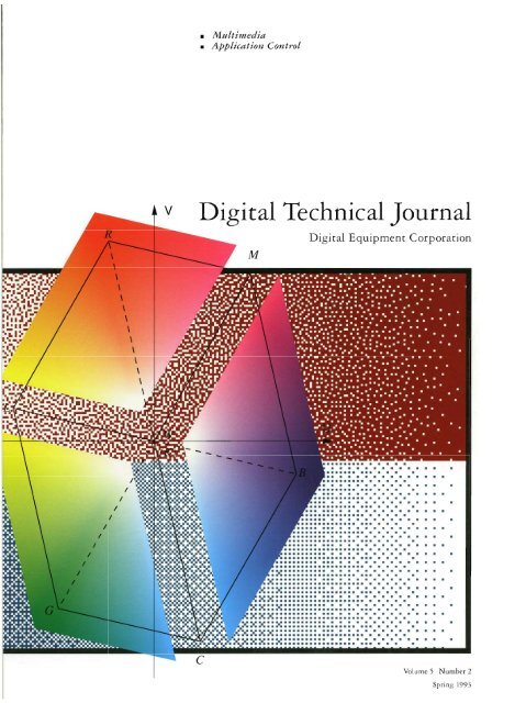
EditorialJane C. Blake, Managing EdltorKathleen M Stetson, Ed~torHelen L. Patterson, EditorCirculationCatherine M. I'hillips, AdministratorDorothea B. Cassady, SecretaryProductionTerri Auticri, Production EditorAnne S. Katzeff, vpographerPeter R. Woodbury, IllustratorAdvisory BoardSamuel H. Fuller, Chairmankchard W BemeDonalcl 2. HarbcrtRichardJ. HollingsworthNan G. NemethJeffrey H. RudyStan SmitsMichael C. ThurkGayn B. WintersCover DesignDithering and color space conversion are twoof the concepts discussed in "Video Rendering,".which opens this issue's set ofpapers on multimediatechnologies. On the covw the bandof blue across the bottom of the cover graphicshows the rectangularpatterning createdby an ordered ditherprocess using a populccrrecursLue tessellation array The band of burgtrtzdyacross the top shows the sziperiorpatterningof the same ordered ditherprocesswith a newly designed void-ancl-cluster array,which produces a higher quality image for displayby eliminating the rectangulc~r patternsand the textrires of white noise. The line illustrationoverlayiiag these two arrays presentstwo color spaces, one within the other: RGBand YW(Itiminance-chrominance space usedby television systems; Y axis not shown). In thecolor conversion process, data transmittedin YWspace is converted lo RGB space. Thecover design shows threefc~ces ofthe RGBspace "lifted o r ancl infused with the colorsnoted at each corner oftheparallelepiped,The cover concept and ill~rstrations arederived from the paper "Video Rendering"by Bob Ulichney. The design was implementedby Linda Falvella of QuanticCommunications, Inc.The <strong>Digital</strong> Ecbnicc~lJorr~nal is a refereed journal published quarterly by <strong>Digital</strong>Equipment Corporation, 30 Porter Road LJ02/D10, Littleton, Massachusetts 01460.Subscriptions to the Jou,nal are $40.00 (non-U.S. $60) for four issues and $75.00 (non-U.S. $115) for eight issues and must be prepaid in U.S. finds. University and collcge professorsand Ph.D. students in the electrical engineering and computer science fieldsreceive complimentary subscriptions upon request. Orders, inquiries, and addresschanges should be sent to the <strong>Digital</strong> <strong>Technical</strong><strong>Journal</strong>at the published-by address.Inquiries can also be sent electronically to DTJ@CKL.DEC.COM. Single copies and backissues are available for $16.00 each from <strong>Digital</strong> Press of <strong>Digital</strong> Equipment Corporation,129 Parker Street, Maynard, MA 01754. Recent back issues of the Joufnal are alsoavailable on the Internet at gatekecper.dec.com in the di.rectory /pub/DEC/DECinfo/DTJ.<strong>Digital</strong> employees may sencl subscription orders on the ENET to R.DVAX::JOI'IWi\LOrders should include badge number, site location code, and address.Comments on the content of any paper are welcomed and may be sent to the managingeditor at the published-by or network address.Copyright O 1993 <strong>Digital</strong> Equipment Corporation. Copying without fee is permittedprovided that such copies are made for use in educational institutions by faculty membersand are not distributed for commercial advantage. Abstracting with credit of<strong>Digital</strong> Equipment Corporation's authorship is permitted. All rights reserved.The information in the <strong>Journal</strong> is subject to change without notice and should not beconstrued as a commitment by <strong>Digital</strong> Equipment Corporation. Digival EquipmentCorporation assumes no responsibility for any errors that may appear in the <strong>Journal</strong>.ISSN 0898-901XDocumentation <strong>Number</strong> EY-P963E-DPThe following are trademarks of <strong>Digital</strong> Equipment Corporation: Alpha AXP, AXP, CDA,CDD/Repository, COHESION, CX, DDJF, DEC, DEC 3000 AXP, DEC CkiC;l;rnce, DEC OSWlAXP, DECaudio, DECchip 21064, DECimage, DECnet, DECNIS, DECpc, DE(:spin,DECstation, DECvideo, DECwindows, <strong>Digital</strong>, the <strong>Digital</strong> logo, GIGAS\VI'I'CN, HSCSO,Megadoc, OpenVMS, OpenVhlS AXP, Q-bus, RA, RV20, SQL Multimedia, TURUOchannel,ULTRIX, UNIBUS, VAX, VAXstation, and VMS.Apple, Macintosh, and QuickDraw are registered trademarks and QuickTime is a trademarkof Apple Computer, Inc.Display PostScript is a registered trademark of Adobe Systems Inc.DM and INDEO are registered trademarks and Intel is a trademark of Intel Corporation.HP is a registered traclemark of Hewlett-Packard CompanylOhl is a registered trademark of International Business Machines Corporation.Kodak is a registered trademark of Eastman Kodak Company.Lotus and 1-2-3 are registered tradcmarks of Lotus Development CorporationMicrosoft, MS-DOS, and Excel are regisrered trademarks and Video for Windows.Windows, and Windows NT are tradcmarks of Microsoft Corporation.MIPS is a trademark of MIPS Computer Systcms.Motif, OSF, and OSWl are registered tradcmarks and Open Software Foundation is atrademark of Open Software Foundation, Inc.Perceptics is a registered trademark and LascrStar is a trademark of PerccpticsCorporation.SCO is a trademark of Santa Cruz Operations, IncSolaris, Sun, and SunOS are registered trademarks and SPARCstation is a trademark ofSun Microsystems, Inc.SPARC is a registerecl trademark of SPARC International, Inc.System V is a trademark of American Telephone and Telegraph Company.UNM is a registered trademark of UNK System Laboratories, IncXvideo is a trademark of Parallax Graphics, Inc.X Window System is a trademark of the Massachusetts Institute of Technology.Book production was clone by Quantic Communications, Inc.
Contents7 ForewordJohn A. MorseMultimedia9 Video RenderingRobert Ulichney19 SoJtware Motion PicturesBurkhard K. Neidecker-Lutz and Robert Ulichney28 <strong>Digital</strong> Audio CompressionDavis Yen Pan41 The Megadoc Image Document Management SystemJan B. te Kiefte, Robert Hasenaar, Joop W Mevius, and Theo H. van Hunnik50 The Design ofMultimedia Object Support in DEC RdbMark F. Rile): James J. Feenan, Jr., John L. Janosik, Jr., and T. K. Rengardjan65 DECspim A Networked Desktop Videoconferencing ApplicationLawrence R. Palmer and Ricky S. Palmer77 LAN Addressing for <strong>Digital</strong> Video Datal'eter C. HaytlenApplication Corltrol84 CASE Integration Using ACA ServicesPaul 0. Patrick, Sr.100 DEC @aGlance-Integration ofDesktop Tools andManufactun'ng Process Information SystemsIlavid Ascher
I Editor5 IntroductionJane C. Blake~Vunqqing EditorThis issue of the <strong>Digital</strong> <strong>Technical</strong>Jotrr~zal featurespapers on multimetlia technologies ant1 applications,and on uses of the Application ControlArchitecture (ACA), <strong>Digital</strong>'s implementation of theObject Management Group's CORHA specification.The high quality of today's television, film, andsound recordings have set expectations for computer-basedmultimedia; we expect high-qualityimages, fast response times, good quality audio,availability-including network transmission, andall at "reasonable" cost. Bob Ulichney has writtenabout video image-rendering methotls that are it1fact fast, simple, and inexpensive to implement. Hereviews a color rendering system and conlparestechniques that address the problem of insufficientcolors for displaying video images. Dithering is oneof these techniques, and he describes a new algorithmwhich provides good quality color and highspeedimage rendering.The dithering algorithm is utilizetl in SoftwareMotion Pictures. SIMP is a method for generatingdigital video on desktop systems without the needfor expensive decompression hardware. BurkhardNeidecker-Lutz and Bob Ulichney tliscuss issuesencountered in designing portable vitleo compressionsoftware to display digital video on a range ofdisplay types. SMP has been ported to Alph;~ AXP,Sun, IBM, Hewlett-Packartl, and Microsoft platforms.Digitized data-video or audio-must be compressedfor efficient storage and transmission.Davis Pan surveys audio compression techniques,beginning with analog-to-digital conversion anddata compression. He then discusses the MotionPicture Experts audio algorithm and the interestingproblem of tleveloping ;I real-time software implementationof this algorithm.Even conipressctl, digitizetl data takes up tremendousm mounts of storage space. A relationaldatabase can not only store this data but providefast retrieval. Mark Riley, Jay Feenan, John Janosik,and T.K. Rengarajan describe DEC Rdb enhancementsthat support multimedia objects, i.e., text,still frame images, compountl documents, andbinary large objects.Managing image documents is the subject of apaper by Jan te Kiefte, Bob Hasenaar, Joop Mevius,and Theo van Hunnik. Megadoc is a hartlware andsoftware framework for building custon~ized imagemanagement applications quickly and at low cost.They describe the UNIX file system interface to\VOliM tlrives, a storage manager, ant1 ;In image;~pplication framework.Distributing multimedia over a network presentsboth engineering challenges and opportunities forapplications. DE
Biographies IDavid Ascher Dave Ascher joined <strong>Digital</strong>'s Industrial Products SoftwareEngineering Group in 1977 to work on the DECDataway industrial multidropnetwork. Since then, he has worked on distributed manufacturing systems asa developer, group leader, and technical consultant, and as an architect of theDEC @aGlance product. As a principal software engineer, Dave leads an effort todevelop DEC BaGlance service offerings. He holds a B.S. in psychology from CityCollege of New York and a Ph.D. in psychology from McMaster University,Hamilton, Ontario.James J. Feenan, Jr. Principal engineer Jay Feenan has been implementingapplication code on database systems since 1978. Presently a technical leader forthe design and implementation of stored proced~~res in DEC Rdb version 6.0, hehas contributed to various Rdb and DBMS projects. Prior to joining <strong>Digital</strong> in1984, he implemented Manufacturing Resource Planning systems and receivedAmerican Production and Inventory Control Society certification. Jay holds a B.S.from Worcester Polytechnic Institute and an M.B.A. from Anna Maria College.He is a member of the U.S. National Rowing Team.Robert Hasenaar Bob Hasenaar is an engineering manager for the Megadocoptical file system team, part of <strong>Digital</strong>'s Workgroup Systems SoftwareEngineering Group in Apeldoorn, Holland. He has seven years' software engineeringexperience in operating systems and image document management systems.Bob was responsible for the implementation of the first Megadoc opticaldisk file system in a UNlX context. He has an M.Sc. degree in theoretical physicsfrom the University of Utrecht, Holland.Peter C. Hayden Peter Hayden is an engineer in the Windows NT SystemsGroup. He joined <strong>Digital</strong> in 1986 as a member of the FDDI team and led severalefforts contributing to the development of the FDDI technology and product set.He then led the Personal Computing Systems Group's multimedia projectsbefore joining the Windows NT Systenls Group in 1992. Before coming to <strong>Digital</strong>,Peter worked on PBX development at AT&T Bell Laboratories. He holds a B.S. inelectrical engineering and an M.S. in computer science from Union College inSchenectady, NY, and has several patent applications pending.
John L. Janosik, Jr. A principal software engineer, John Janosik was the projectleader for DEC Rdb version 5.0, the Alpha ASP port version. John has been amember of the Database Systems Group since joining <strong>Digital</strong> in 1988. Prior tothis, he was a senior software engineer for Wang Laboratories Inc. and workedon PACE, Wang's relational database engine and application development environmcnt.John received a B.S in computer science from Worcester PolytechnicInstitute in 1983.Joop W. Mevius A systems architect for the Megadoc system, Joop Mevius hasover 25 years' experience in software engineering. He has made contributionsin the areas of database management systems, operating systems, and imagedocument management systems. Joop has held both engineering managementpositions and technical consultancy positions. He has an M.Sc. clegree in mathematicsfrom the <strong>Technical</strong> University of Delft, Holland.Burkhard K. Neidecker-Lutz Burkhard Neiclecker-Lutz is a principalengineer in the Distributed Multimedia Group of <strong>Digital</strong>'s C;~mpus-basedEngineering Center in Karlsriihe. He currently works on distributecl multirnecliaservices for broadband networks. Burkhard contributed to the XMedia layeredprocluct. Prior to that work he led the design of the NESTOR distributed learningsystem. He joined <strong>Digital</strong> in 1988 after working for PCS computer systems.Burkhard earned an M.S. in computer science from the University of Karlsriihein 1987Lawrence G. Palmer Larry Palmer is a principal engineer with the NetworksEngineering Architecture Group. He currently leads the DECspin project for thePC ant1 has been with <strong>Digital</strong> since 1984. Larry is one of three softw~re developerswho initiated the PLMAX software project for the DECstation 3100 product byporting the ULTRlX operating system to the MIPS architecture. He has a B.S. (highesthonors, 1982) in chemistry from the University of Oklahoma ancl is a memberof Phi Beti1 Kappa. Hc IS co-inventor for five patents pending on enabling softwaretechnology for audio-video teleconferencing.(%'Ricky S. Palmer liicky Palmer is a principal engineer with the ConlputerSystems Group. He joined <strong>Digital</strong> in 1984 and currently leads the DECspin project.Ricky is one of three software developers who initiated the I'NwX softwareproject for the DECstation 3100 product by porting the ULTRIX operating systemto the MII'S architecture. He has a B.S. (high honors, 1980) in physics, a B.S. (1980)in mathematics, and an M.S. (1982) in physics, all from the University ofOklahoma. He is co-inventor for five patents pending on enabling software technologyfor audio-video teleconferencing.
Davis Yen Pan Davis Pan joined <strong>Digital</strong> in 1986 after receiving a Ph.D. in electricalengineering from MIT. A principal engineer in the Alpha Personal SystemsGroup, he is responsible for the development of audio signal processing algorithmsfor multimedia products. He was project leader for the Alpha/OSF baseaudio driver. He is a participant in the Interactive Multimedia Association <strong>Digital</strong>Audio <strong>Technical</strong> Working Group, the ANSI X3L3.1 <strong>Technical</strong> Worliing Group onMPEG standards activities, and the ISO/MPEG standards committee. Davis is alsochair of the ISO/MPEG ad hoc committee of MPEG/audio software verification.Paul B. Patrick, Sr. Paul Patrick is a principal software engineer in the A
BiographiesIRobert Ulichney Robert Ulichney received his Ph.D. (1986) in electrical engineeringand computer science from the Massachusetts Institute of Technologyand his B.S. (1976) in physics and computer science from the University ofDayton, Ohio. He is a consulting engineer in Alpha Personal Systems, where hemanages the Codecs and Algorithms Group BOO has nine patents pcnding forhis contributions to a variety of <strong>Digital</strong> products, is the author of <strong>Digital</strong>Hnlftoni~zg, published by The MIT Press, ant1 herves as a referee for several technicalsocieties includingrEEE.Theo M. van Hunnik Theo van Hunnik is an engineering project manager for<strong>Digital</strong>'s Workgroup Systems Software Engineering Group in Apeldoorn. Holland.He has over 20 years' software engineering experience in compiler developmentand the tlevelopment of office automation protlucts. Theo has participated inseveral international systems architecture task forces. He managed the developmentteam for RetrievAll, the Megadoc image application framework.
I ForewordJohn A. MorseSr: Engineering Munc~gel;Corporate Research GArchitectureIn the late '80s, "multimedia" was a magic word.It seduced us with glimpses of a brave new worldwhere audio ant1 vitleo technology merged withcomputer technology. It promised us everythingfrom instant high-impact business presentationsto virti~al reality. Words like "paradigm shift" and"multibillion-dollar intlustry" were enough to snareboth the technophilcs and the eager entrepreneursinto believing that the world had suddenlychanged, and we were all going to get rich in theprocess.Somewhere on the way to the bank, reality set in,ant1 it wasn't virtual. The reality is that multimedia isa lot harder than it looks. S~~ccessh~l rni~ltimetliarequires ;I marriage between analog 'W technologyand digital computer technology; it requires reconciliationbetween a technical/professional marketplaceand a consumer marketplace. As in anymarriage, a lot of hard work is required to make itsucceed, and much of that work is yet to be done.For certain segments of the computer industr):multimedia was relatively easy to implement ant1 socaught on quickly. The first successes have been atthe extremes of the cost spectrum-very low-endclesktop multimedia on the one hancl, and veryhigh-entl virtual reality systems on the other. Thishas left <strong>Digital</strong>, with its traditional focus on themitltlle, temporarily out of the game.For desktop multimedia, all that is reqi~ired is theability to capture and display video and audio. Sincemachines like the Commodore Amiga were alreadybased more on Tv technology than on computertechnology (for cost reasons), they coultl be quicklyant1 cheaply adapted to handle audio and motionvideo. Thus desktop multimedia was born. TheCD-ROM, adapted from autlio CD technology, was theperfect storage rnetlii~rn for distribution of multimediacontent; and so for this market segment,CD-ROM and multimedia became almost synonymous.There has emerged a whole industry based aroundthe production of multimedia titles on CD-ROM.At the high end, for purposes such as full-realismaircraft simulation or virtual reality applications,the solution was to use the highest performancehardware available, at whatever expense. Typically,high-end, three-dimensional graphics systems werecoupled either to supercompilters or to massivelyparallel processor arrays. The result was, and still is,impressive. But the cost is still so high that such virtualreality systems arc not yet commercially viableexcept in specialized low-volume markets.The vast area in the middle, into which all of<strong>Digital</strong>'s business falls, has developed very slowly.The problem is that our business is based on amodel of enterprise-wide computation. The computersystems we design ant1 sell not only inclucleprocessors and displays but incorporate networksand servers as well. To introduce multimedia intosuch a model, one touches every aspect of the system,from the desktop, through the network, andback to the servers. At every turn, we have foundthat the technology that has evolved over 30 to 40years for handling numbers, text, and (morerecently) two-dimensional and three-dimensionalgraphics is not quite right for video and audio.Every component of the system, both hardware andsoftware, needs to change in some way. We need toevolve to a model of networked client-server multimediacomputing. Change of this magnitude is aslow process.Two challenges are so pervasive that alniostevery paper in this issue addresses them, each froma different perspective. First of all, multimediainvolves the handling of large quantities of data.Second, for many applications, that data must behandled under very tight time constraints. Theresulting stress and strain on all components of thesystem translates into a set of technical challengesthat has occupied us for the last four years andprornises to keep us busy through at least the rest ofthis decade.Depending on the picture quality chosen, it mayrequire from one million to one hundred millionbytes of storage to save each second of live video indigital form. Since many applications of multimedia,such as archiving television footage forresearch or historic preservation purposes, willneed to save many hozirs of video, it is easy to see
th21t n~ultimedia quickly builds dem;lnd for manygigabytes (1,000,000,000 bytes) of magnetic or opticaldisk storage. But storage is only part of the problem.Once such enormous amounts of data arestored, the challenge becomes how to retrieve aparticular item of interest. Standard database techniquesare orielited toward retrieval of text andr~un~bers. Retrieval of autlio ant1 video informationwill require new file and database techniclues that;ire only beginning to be untlers~ood.An obvious application of multirnedia technology,once the networks are in place, is teleconferencing.We can envision a day when we canconnect to anyone any place in the world via thenetwork ant1 carry on a conversation with them,while each of us sees the other in full-motion video,using the a~~dio ant1 vitleo capabilities of our clesktopworkstations and PCs. But realizing this visionhas proved surprisingly hard. People expect theimages they see to be synchronized with. the soundsthey hear, and they expect delays to be no worsethan tliose experienced on a long-distance telephonecall. Unfortunately, data networks have beendesigned to maximize throughput and reliability.They do this at the expense of some delay in transmission-delaythat is annoying at best, and unacceptableat worst, foi- teleconferencing applications.Successful infusion of multimedia technologyinto enterprise-wide computation is proving torequire change on a scale that almost no one anticipated.We at <strong>Digital</strong> are in the midst of this processof change, ant1 this issuc of the <strong>Digital</strong> <strong>Technical</strong>Jozirrzcrl is a snapsliot, t;~ken at one point in time, ofthat process. Together, the papers describe some ofthe toughest technical challenges that we face andin many cases give glimpses into possible solutions.
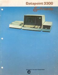
Robert Ulicbney IVideo RenderingWdeo rendering, the process of generating device-dependent pixel data fromdevice-independent sampled image data, is key to image quality. System componentsinclude scaling, color adjustment, quantization, and color space conuersion.This paper emphasizes methods that yield high image qualit34 are fc~st, and ye1 aresimple and inexpensiue to implement. Particular attention is placed on the dc~iuationand analysis of new multilevel dithering schemes. While permitting smallerframe bzlffers, dithering also prouides faster transport of the processed image to thedisplay-a k q benefit ~ for the massive pixel rates associated with full-motion videoPerhaps the most influential characteristic governingthe perceived value of a system that displaysimages is the way the pictures look. Image appearanceis largely dependent upon the quality of rendering,that is, the process of taking device-independentdata and generating device-dependent data tailoredfor a particular target display.The topic of this paper is the processing of sampledimage data and not synthetic graphics. Forgraphics rendering, primitives such as specificationsof triangles are converted to displayable pictureelements or pixels. The atomic elementshandled by a video rendering system are deviceindependentpixels. Whereas a prerendered graphicsimage can be compactly represented as acollection of triangle vertices, prerendered videoachieves compaction by means of compressiontechniques.Sampling broadcast video requires a data rate ofmore than 9 million color pixels per second; theneed of some relief for storage and networks isclear. Video compression reduces redundancy inthe source image and thereby reduces the amountof data to be transmitted. Dramatic reductions indata rate can be achieved with little degradation inimage quality. The Joint Photographic ExpertsGroup (JPEG) standard for still frame and theMotion Picture Experts Group (MPEG) and Px64standards for motion video are current committeecompression techniques.' Several other nonstandardschemes exist, including a simple compressionmethod conclucive to software-onlyimplernentati~n.~Vicleo rendering receives decompressed imagedata as input. Since every decompressed pixel mustbe processed, speed is essential. This paper focuseson rendering methods that are fast, simple, andinexpensive to implement. Performance at videorates can be achieved with minimal hardware oreven software-only solutions.The Rendering Architecture section reviews thecomponents of a rendering system and examinesdesign trade-offs. The paper then presents detailsof new and efficient dithering implementations.Finally, video color mapping is discussed.Rendering ArchitectureFigure 1 illustrates the major phases of a video renderingsystem: (1) filter and scale, (2) color atljust,(3) quantize, and (4) color space convert.In the first stage, the original image data must beresampled to match the target window size. A separatescaling system should be used for the horizontaland vertical directions to handle the case wherethe pixel aspect ratio must be changed. For example,such asymmetric scaling is needed when thetarget display expects square pixels and the originalpixels are not square.The best filters to use in combination with scalinghave been determined from a perceptual pointof view.? When limiting the bandwidth to reducethe data rate, a Gaussian filter with a standard deviationu = 0.30 X output period is recommended.For interpolation, the filter preferred (because thefiltered results looked most like the original) wasa cascade of two: first, sharpen with a Laplacianfilter, and second, follow by convolution with aGaussian filter with u = 0.375 X input period.A typical sharpening scheme can be expressedby the following equation:I,,,,,, [x,yI = I[XJJI - P*\II[x,yI * J[x,yI, (1)<strong>Digital</strong> <strong>Technical</strong> Jourrral Vo1.5 No. 2 Sprtng 1993
MultimediaIIIIFigure IDECOMPRESSEDIMAGE DATAFILTERAND SCALEaADJUSTQUANTIZESPACECONVERT*---RENDERED PIXELSImage Rendering Systemwhere I[x, y] is the input image, 9[x, y] is a digitalLaplacian filtcr, and "*" is the convolution ~perator.~The nonnegative parameter P controls tlie degreeof sharpness, with p = 0 i~itlicating no change insharpness. When enlarging, sharpening shouldoccur before scaling, and when reducing, sliarpeningshould take place after scaling. The filtering discussedhere is assumed to be two-dimensional,which requires image line buffering. For economy,horizontal-only filtering is sometimes used.The simplest means of scaling is known asnearest-neighbor scaling, and its simplest imple-mentation is based on the Bresenham scan conversionalgorithm for drawing straight li~ies.~ Thisalgorithm can be applied to image scaling ant1 performedwith only three registers and one adder."Further optimizations make this algorithm especiallysuitetl for real-time use.'The second stage of rendering is color adjust,most easily achieved with a look-up table (LIJ'T).Each color component uses a separate adjust 1.liT.In the case of a luminance-chrominance color, anadjust 1.m for the luminance component controlscontrast and brightness, and LUTs for the chrominancecomponents control saturation.For so-called true-color frame buffers with 24-bitdepths, visual artifacts that can result from insufficientamplitude resolution do not occur. Withsmaller frame buffers, restricting the amplitucle ofthe color components red, green, and blue (R
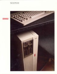
of amplitude resolution per color component, the2-by-2-pixel case results in an average of ((2 X 2 X 8luminance bits) + (8 + 8 chrominance bits))/(2 X 2 pixels) or 12 bits per pixel; similarly, the4-by-4-pixel case results in 9 bits per pixel. Thisapproach requires expensive hardware to up-samplethe chrominance components and convert thecolor space at vitleo rates. These nonstandardframe buffers can also cause severe incompatibilityproblems with most applications that expect RGDframe buffers. While chrominance subsampleclframe buffers can accommodate most sampled naturalimages, thin-line graphics can be annihilated.The third alternative for quantization is to usea dithering method. Several methods exist that aredesigned primarily for binary output, but all areextendable to multilevel color.' li A "level" is ashacle of gray, from black to white, or a shade ofa color component, from black to the brightestvalue. The basic principle of dithering is to use theavailable subset of colors to protluce, by judiciousarrangement, the illusion of any color in between.Although neighborhood operations, most notablyerror diffusion, produce good-quality dithering,they are computationally complex and requireadditional storage. For video processing, wherespeed is essential, we turnetl our focus to thosedithering methotls that are point operations, that is,methods that operate on the current pixel onlywithout considering its lleighhors. Each color coniponentof every pixel in the image has an associatetl"noise" or tlither amplitude that is added to it beforethat component is passed to a uniform quantizer.Historically, the first dithering method used forvideo processing was white noise dithering, wherea pseudorandom number was adtled to each luminancevalue before quantization. This method waspracticed soon after the dawn of television.I6However, the low-frequency energy in white noisecauses undesir;~ble textures and graininess.A preferred method is the point process ofordered dithering, where a tleterministic noisearray tiles tlie plane in a periodic manner. Ditherarrays can be tlcsigned to mi~iiniize low-frequencytexture. The most popular are tlie so-called recursivetessellation arrays.l7lVThese arrays yield resultssuperior to those of white noise dithering but sufferfrom structured rectangular patterns.A new ortleretl tlither array design, called the"void-and-cluster" method, eliminates both the lowfrequencytextures of white noise and the rectangularpatterns of recursive tessellation arrays.I9 Thename describes the dither array tlesign process inwhich voids and clusters are located and mitigated.For the high-speed case of motion video, anordered dithering scheme has important advantagesover chrominance-subsampled frame buffersand histogram-based approaches. Quantization bydithering allows the use of conventional franiebuffers, does not require tlie time-consuming processof making two passes over each frame (oreve17 Nth frame), does not cause other applicationsto change color maps with every Nth frame, andallows any number of colors to be selected at rendertime. Also, experiments have shown that theimage quality achieved by dithering is very competitivewith the other methods, when comparecl overa range of sample images. Even when 24-bit framebuffers are available, the increasetl speetl of loadingthree or four 8-bit color pointers or index values inthe time required to load a single 24-bit pixel makesdithering a viable alternative in the design of desktopvideo systems.By way of comparison, Figure 2 illustrates sonicof the methocls described in this section. A 240-by-560-pixel, 8-bit monochrome image was renderedto only two levels and displayetl at 100 dots per inch(dpi). Figure 2a depicts an image that was ditherctlwit11 white noise; in Figure 2b, the same image wastlitherecl using an 8-by-8 recursive tessellationdither array; and Figure 2c shows the imageditherecl with the new 32-by-32 voicl-and-clusterarray. To illustrate the effect of sharpening, Figure2d shows the image in Figure 2c presharpenetlusing a digital Laplacian filter as in equation (I),with a sharpening factor of = 2.0. The goal of thiscoarse example is to ampl@ the different effects.Tlie same methods apply to multilevel and coloroutput, where the resulting quality is much higher.Fast Multilevel DitheringThis section presents the cletails of simple, yet powerfulnew designs to perform multilevel ortleretldithering. Tlie simplicity of these methods allowsfor imp1ement;ltion with minimum hardware orsoftware only, yet guarantees output that preservesthe mean of the input. The designs are flexible inthat they allow dithering from any number of inputlevels 4, to any number of output levels No, provicledA; 2 IY,. Note that and A;, are not restrictedto be powers of two.Each color component of a color image is treatedas an indepentlent image. The input image Li c;lnhave valuesDigitul Technicnl Jorrrtral I/'( 5 /\'o 2 \/II.III~ I993 1 1
Multimedia(a) Dither with a White Noise Breshold(6) Dither with an 864,-8 RecursiiwTesselllntion Threshold Arrojl(c) Dither zuitb a 32-6~,3,-.32 Void-ancl-cl~isterTlireshold An-aj~(61) Smne as (c) zuitl'l LLI~INCI'UIZ .Y/x?rflenitl~,p = 2.0Figure 2 Ex6i1npke.s of Rendering to ~ ~ LOutpttt Y J LezMsLi€ {0,1,2,..., (l'y - I)),and the output image L , can have valuesA deterministic dither array of size M X N is usedthat is periodic and tiles the entire input image. Tosimplify aclclressing of this array M and i\r 5houltleach be powers of two. A tlither template definesthe order in which dither values are arranged. Theelements of the dither template T have valuesTE {0,1,2,..., (4 - I))>where IV, is the number of template levels, whichrellresent the levels ag:~inst which image inputvalues are compared to determine their ni;~ppingto the output values. The tlither template is thuscentral to determining the nature of the resultingdither patterns.Figure 3 shows a dithering system that comprisestwo memories and an atlcler. l'he system takes aninput level Li at image location lx,.y] and producesoutput level Lo at the corresponding location in thedithered output image. The dither array is addressedby x'antl y', which represent the low-orcler bits of
Video Renderingx'-IOne-menzory Dithering System+ ARRAY Using the above expressions, it is possible to sim-Figt~re 3 Dithering Systern with Tujo LUTsthe image address. The selected dither valued[x: y'] is added to the input level to produce thesum s. This sum is then quantized by addressing aquantizer I.UT to produce the output level L,,.The trick to achieving mean-preserving ditheringis to properly generate the LUT values. The ditherarray is a normalized version of the dither templatespecifiecl as follows:d[x:y'l = int (A,(T[x: y'] + i)),where A,, the step size between normalized dithervalues. is defined asand AV isthe quantizer step size(N, - 1)A =--U cry, - 1)Note that AQ also defines the range of dither values.The qi~antizer LUT is a uniform quantizer with A;equal steps of size Ag.The precise expressions in equations (2), (3), and(4) were ;irrivetl at through extensive al~alysis of theaverage oi~tpi~t resulting from processing inputimages of a constant value, over a wide range of y,y,, and N,.pllfy the system by exchanging one degree of freedomfor another. A bit shifter can replace thequantizer LUT at the expense of forcing [he numberof input levels 4, to be set by the system. For hardwareimplementations, this design affords a considerablecost reduction.The system and method of Figure 3 assume thatq. is given as a fixed parameter, as is usually the casewith most imaging systems and file formats.However, for image sources such as hardware thatgenerates synthetic graphics, arbitrarily setting N;.often has no effect on the amount of computationinvolvetl. If an adjust LUT is used to modify theimage data, including a gain makes a "modifiedadjust LUT." Figure 4 depicts such a system, whereL,. is the raw input level. The unadjusted or rawinput image can have the valuesL,. € {0,1,2,. . .,(fV. - 111,where q. is the number of raw input levels, typically256. Therefore, the modified adjust LIJT mustimpart a gain of4. - 11y. - 1 'To solve for 4, recall that in the method of Figure3 the quantizer was defined to have equal steps ofsize AQ as definecl in equation (4). The qi~antizerLUT can be replaced by a simple R-bit shifter, if thevariable Ap can be forced to be an exact binarynumber,A, = 2Y (5)4 can then be set by the expressionN;. = (1V0 - 1)2~ + 1. (6)The integer R is the number of bits the R-bitshifter shifts to the right to achieve quantization.Speceing R in terms of q,, equation (6) becomes- Lr[x.yI ADJUSTMODIFIEDLUTI dlx' v'lSHIFTERFigure 4One-memory Dithering System with an Adjcut LUTand Bit ,Bfyter<strong>Digital</strong> Technicul Jour?~aI Vol. 5 No. 2 Spring 1993 13
MultimediaR = log,(q - 1)(4, - 1)'To completely specify this problem requires specifyingthe range for 4,. It is rcason;tble to do this byspecifying the number of bits 6 by which the imageinput values are to be represented. Specifying 6lilliits I\: to tlie rangeParameter 6 will be a key value in specitjling tlieresultin&. ' s y stem.Given the two expressions, (7) and (8), and thetwo unknowns. R and A:, a unique solution existsbecause tlie range of IY. is less than a factor of two.and R ant1 A$ are integers. To solve for R, substituteequation (6) for N, in equation (8). The res~~ltingequation islog - - 1) < R s l o( )(10)N" - I 4, - 1Since 2 I 4, 5 A:., the range of the expression inequation (10) must be less than one. Hence, give11that K is ;in integer,(*)IR = int [log24) - 1in equation (6) is now specified.As an example, consitler the case where 4,equals 87 (levels), 6 eqilals 9 (bits), 4 equnls 1,024(levels, for a 32-by-32 templ;ite). and IY. eqilals 256(levels). 'T'hus, R equals 2, ant1 the R-bit shifter dropsthe least-significant 2 bits. 4. equals 345 (levels);the tlither ;trrav is norni:~lizetl by equation (2) withA, = 1/256; and the gain factor to be incluclrd in themodified adjust LUT is 344/255. This data is loatledinto the system represented by Figure 4 i~ntl uni-formly ni;~ps input pixels ;tcross tlie 87 true outputlevels, giving the illusion of 256 levels.The output image that results from either of thedithering systems illustratetl in Figure 3 or Figure 4appears to contain more effective levels than areactu:~lly displayed. An effective level is either a perceivetlaverage level that is tlitheretl between twotrue oi~tlx~t levels or shades or an actual true outputlevel. k small nuniher of tenlplate levels 4 clictatesthe resulting number of effective levels. \Vhen4 js I;trge, the number of effective levels is equalto the number of input levels I\:, because it is notpossible to display more effective outputs thaninputs. [More precisely,Effective Levels = 1 (12)Note that Aa/N, in equation (12) is equal to A,/.When A , < 1, the normalization of the tlither array,i.e., equation (2), results in integer truncated valuesthat are not all unique. At this point, the number ofeffective levels saturates to N,.Data Width AnalysisThe design of an efficient dithering system, particularlyin hardware, depends on knowing the numberof bits recluired for all data paths in the system. Thissection presents an analysis of the one-memorydithering system shown in Figure 4.The system input 6, it., the bit depth of theimage input values, limits tlie data path for L,lx;y].The analysis shows the derivation of the precise bitdepths for the other dat;~ paths. In summary, tlietlerivation proves that the dither values in thedither matrix memory recluire R bits, where Rllll,, =(I? - I) and s = Li + d (and thus tlie R-bit shifter)require only 6 bits.Bits iVee~/e~/ fbr Dither iP1~1Lrin' The amount ofmemory needed to store the dither matrix is animport;~nt COIIC~~II; d,l,l,,,, denotes the maximumvalue. To determine dlll~,,, substitute the maximi~mvalue of T[x: y 'I, which is (IV, - l), into equation(2).'['he resulting equation isdl,,,,, which depends on iV,, thus has a value in therange1;or the case of ;I dither matrix with one value,namely A, = 1, equals the lower end of thisrange. dl,,,, equals the high encl of the range forlarge dither nlatrices, where 2R-' 5 N,. An iniportantobservation is that for all valiles in the range ofexpression (14), the number of bits needetl isex:tctly K.
Vi~leo RenderingFrom equation (ll), the value of R increases as Nodecreases. The smallest possible value of No is 2,which is for biton;~l output. In this case, the maximumvalue of R isSo, the number of bits needed for the dither valuesis R, which can be as large as (b - 1).Bit Width oj'Aclder Recall that s[x,y] = L,[x,y] +d[x, y]. The number of bits needed for this sumdetermines the size of the adder and the size ofthe R-bit shifter. L, can be at most (A:. - I) and, asdetermined in the last section, d,,, can be at most(zK- 1). SO,From equation (6),which givess,,,~~ = ~ ~ (- 41) , + (2'- 1) = 2'% - 1. (18)\Ve can express R in terms of No by using equation(11):R = int(logl(2" - 1) - log, (Nj, - 1)). (19)Each of the two terms in the equation (19) can beexpressed in terms of :un integer part and a fractionalpart:wherelog,(2" - 1) = (6 - 1) + E l,log,(ly, - 1) = K + E,,where K is an integer, and01c2< 1.Now equation (19) can be rewritten asR=(O-1)-K+int(~,-E,) (22)E, IS largest when 4, (an integer) is a large power of2 Because iV, cannot be greater than 4,2" 24,.This fact, combinetl with equations (20) ancl (21),yields the further contlitionEl 2 E,.Therefore, int(~, - E,) in equation (22) must beequal to zero, and the value of R becomesR=b-1 -K. (23)We can express No in equation (18) in terms of thesame integer K of equation (21) by noting thatwherelog, ly, = K + E3. (24)O
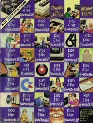
MultimediaPrior to proceeding to the quantize subsystemshown in Figure 1, all color components must be atthe same final spatial resolution for a ditheringmethod to work correctljr. Chrominance components,then, need to be up-sampled to the same rateas luminance components.Although the chromaticities of the RGB primariesof the major television standards vary slightly, alltelevision systems transmit and store the color datain YUV space. Y represents the achromatic componentthat is loosely called the luminance cornponent.(The term luminance has a specificphotometric definition that is not what is representedin a video Y component.) U and V are colordifference components, where U is proportional to(Blue - Y) and V is proportional to @ed - Y).Figure 5 is an orthographic projection of ylrvspace. Inside the W rectangular solid is the( (Y-axis out)FQure 5 Feasible RGB Values in the YW Color SpaceVol 5 No 2 Spring 199.3<strong>Digital</strong> Technicof Jourrral
parallelepiped of "feasible" RGB space. Feasible RGBpoints are those that are nonnegative and are notgreater than the maximum supported value. For reference,the corners of the RGB parallelepiped arelabeled black (K), white (W), red (R), green (G),blue (B), cyan (C), magenta (M), and ~rellow (L). KGBand W values are related linearly and can be interconvertedby means of a 3-by-3 matrix multiply.In the United States video broadcast system, thechrominance plane (i.e., the U-V plane in Figure 5)is rotated 33 degrees by introducing a phase in thequatlrat~lre modulation of the chrominance signal.The resulting rotated chrominance signals arerenamed I and Q (for inphase and quadrature), butthe unmodulated color space is still W.Figure 6 shows the back end of a rendering systemthat uses dithering as a quantization step priorto color space conversion. A serenclipitous consequenceof dithering is th21t color space conversioncan be achieved by means of table look-up. Thecollective address formed by the dithered Y, U, andV values is small enough to require a reasonablysized color mapping LUT. There are two advantagesto this approach. First, a costly dematrixing operationis not required, ant1 second, infeasible RGB valuescan he intelligently mapped back to feasiblespace off-line during the generation of the colormapping LIIT.This second advantage is an important one,because 77 percent of the valid W coortlinatesare in invalid RGR space, i.e., the space around theRGB parallelepiped in Figure 5. Color adjustmentssuch as increasing the brightness or saturation canpush otherwise valid KGB values into infeasiblespace. In alternative systems that perform colorconversion by dematrixing, out-of-bounds RGB val-DITHERSYSTEMSYSTEMRGB--t COLORINDEX1Fig~~re 6 System for Dithering Three-colorCompotzent.~ and Color Mclppingthe Collectiue Resultues are simply truncated. This operation effectivelymaps colors back to feasible RGR space along linesperpendicular to a parallelepiped surklce illustratedin Figure 5, which can change the color in anundesirable way. The use of n color mapping LIITavoids these problems.SummaryVideo is beconling an increasingly important datatype for desktop systems. This is especially true asdistinctions between cornp~~ting, consumer electronics,and communications continue to blur.While many f;~ctors contribute to the impressionone has of the value of a product that tlisplays information,the way the images look can 11i;llie thebiggest difference. This paper focuses on renderingsystem designs that are k~st, low cost, procl~~cegootl-quality video, and are conducive to hardwareor software implementation.References1. Special Issue 077 Digitcil M~lltinzedia .(;3~.slenzs,Com.wi~lnications of the ACfil, vol. 34, no. 1(April 1991).2. B. Neiclecker-Lutz and R. Ulichne): "SoftwareMotion Pictures;' Digitc~l Teclmzicc~l Jo~~nzal,vol. 5, no. 2 (Spring 1993, this issue): 19-273. W Schreiber ancl D. Troxel, "Transformationbetween
Multimedia9. S. Wan, K. Wong, and I? Prusinkiewicz, "AnAlgorithm for Multidimensional Data Clustering,"ACIW Trnnsuctions on Muthemutic~ilSoflzunre, vol. 14, no. 2 (1988): 153-162.10. C. Sigei. R. Abruzzi, and J. ,Munson, "ChromaticSubsampling for Display of ColorImages," Ol~lical Society of Arneric~~ TopicnlMeeling on Applied Vision, 1989 <strong>Technical</strong>D~gest Series, vol. 16 (1989). 158-161.11. A. Luther, <strong>Digital</strong> Video in the PC Enuiromzmeizt(New York, NY: Intertext Publications,McGraw-Hill, 1989): 193-194.12. L. Glass, "<strong>Digital</strong> Video Interactive," Byte (May1989): 284.13. I? Roetling, "Binary Approximation of Continuous-toneImages," Photographic Scienceand Engineering, vol. 21 (1977): 60-65.14. J. Stoffel ant1 J. Moreland, "A Survey ofElectronic 'I'echniques for Pictorial Reproduction,''IEEE Transactions on Co~?zmulziccrtions,vol. 29 (1981): 1898-1925.15. J. Jarvis, C. Judice, and W Ninke, "A Survey ofTechniques for the Display of ContinuoustonePictures on Bilevel Displays," ComnputerCrn,!!hics umzd Image Processing, vol. 5(1976): 13-40.16. \X! Goodall, "Television by Pulse Code Modulat ion," Bell Systems Teclhlical journal, vol.30 (1951): 33-4917 B. Bayer, "An Optimum Method for Two LevelRendition of Continuous-tone Pictures, Proceedingsof the IEEE Internation~il ConferenceOH Co~7znzui~icutior~~, Confere~zceKccord (1973): (26-11)-(26.15).18. R. Ulichney, "Frequency Analysis of OrderedDither," Proceedings of tlx Society of Pbotoo~ltic~~lIizstrzlrrze~?lutiori L3zgil?eers (SPIE),VOI. 1079 (1989): 361-373.19 R. Ulichne): "The Void-antl-cluster Method forIli t her Array Gener;ition," Tl7c Society forIrn~~ging Science and Tcchtzolog~~/~S~~~~zposiiiinon Electronic I~rzclgiiig Science anclTecl!izolog)) (ISGT/SPIE) (February 1993).18 Vol 5 .\lo 2 $p~,~ng 199.3 Digitnl <strong>Technical</strong> Jounrnl
Burkhard K. Neidecker-LutzRobert UlichneySoftware Motion PicturesSoftzvcrre nzotion pictures is a method of generating digital video on general-)Lir/!ose desktop colnl)ulers zvitho~it using special decompression bardivare. Theco~npressio~z algorilhnz is designed for rapid decomnpression in softzuare and generatesdeterministic data rates for use fronz CDROIM and netu~ork connections. Thedecompression part oflers device indepe~zdence and integrates well with existingwi~zdo~u sj~stenls and applicatio~z progralnming ilzteflces. Software motion picluresfecrtures n yortable, low-cost solution to digital video playback.The necessary initial investment is one of the majorobstacles in making video a generic data type, likegraphics and text, in general-purpose computersystems. The ability to display vicleo usually requiressome combination of specialized frame buffer,decompression hartlware, and a high-speed network.A software-only methocl of generating a videodisplay provides an attractive way of solving theproblems of cost and general access but poses challengingqi~estions in terms of efficiency. Althoughseveral digital vicleo standards either exist or havebeen proposed, their computational complexityexceeds the power of most current desktop systems.1In addition, 21 compression algorithm alonedoes not adclress the integration with existing windowsystem hardware and software.Software motion picti~res (SMP) is both a vitleocompression algorithm ancl a complete softwareimplementation of that algorithm. SMP was specdicallydesigned to address all the issues concerningintegration with desktop systems. A typical applicationof SMP on ;I low-entl workstation is to play backcolor digital vicleo at ;I resolution of 320 by 240pixels with a cocled data rate of 1.1 megabits persecond. On a DECstation 5000 Model 240 HX workstation,this task uses less than 25 percent of theoverall rn;tchine resources.Together with suit;~ble ;~i~clio s~~pport (audio supportis beyond the scope of this paper), softwaremotion pictures provides portable, low-cost digitalvideo playback.The SMP Product<strong>Digital</strong> supplies SMP in several forms. The mostcomplete version of SMIIP come5 with the XMediaToolkit This toolkit is primarily clesigned for developersof multimeclia applications who include theSMP functionality inside their own ;~pplications.Figure 1 shows the user controls as displayed on aworkstation screen. SMP players are also availableon <strong>Digital</strong>'s freeware compact disc (CD) for usewith Alpha AXP worltstations running the DEC.:OSF/l AXP operating system. In addition, SMP plapbackis included with several <strong>Digital</strong> products suchas the video help utility on the SPIN (sound pictureinformation networks) application, as well as othervendors' products, such as the MediaImpact multimediaauthoring system.2In the XMedia Toolkit, access to the SMP functionsis possible through X applications, command lineutilities, and C language libraries. The applicationsand utilities support simple editing operations,frame capture, compression, and other functions.Most of these features are intenclecl for use by producersof simple file formats called SivIP clips.The decompression fiinctionality is offerecl as anX toolkit widget that readily integrates into theOpen Software Foundation's (OSF) Motif-basedapplications. Multiple SMP coclecs (compressors/decompressors) on a given screen all share thesame color resources with one another and withthe Display I'ostScript X-server extension, which isoffered by all major workstation vendors. It alsoplays well with the standard color allocations usedin die Macintosh QuickDraw rendering system andMicrosoft Windows standard color allocations.To facilitate flexible but simple access to entirefilms of SMP frames, SMP defines SMI-' clips. Ratherthan publisl~ing that file format directly all applicationsand widgets are accessed through an encapsulatinglibrary. This method allows future releasesto have application-transparent changes to theunderlying file structure and completely differentways to store and obtain SMP frames.<strong>Digital</strong> Tecbrrical Jorirrrcrl Vol. 5 iVo. 2 ,S/>J-;JI~ 199.3
a cotletl dat:~ rate for this size and frame ratethat woultl allow playback from a CD-ROM. TOachieve this goal, we limited tlie cotletl data ratefor the video component to 135 to 142 kilobytesper seconcl for video, leaving 8 to 15 kilobytes persecond for audio. In adtlition, we had to limit fluctuationsof the coded data rate to allow sensibleuse of bandwidth reservation protocols for playbackover a network without coniplex bufferingschemes.More interesting were the issues that becameapparent when we attempted to use the prototypefor real applications. The digital video material haclto be usable on a wide range of display types, anddue to its large volume, keeping specializetl versionsfor different displays was prohibitive. \Yewould li;~ve to adapt the rendition of the codedm;~terial to the device-tlej>enclent color c;rpabilitiesof the target tlisplay at run time.Our design center used 8-bit color-mapped displays.These were (antl still are) the most commoncolor tlisplays, ant1 tlie demonstrator was basedon them. Integration of tlie video into applicationsin a multitasking environment necessitated thatcomputational as well as color resources wereavailable for use by other i~pplications. The systemwoultl have to perform cooperative sharing ofthe scarce color resources on tlisplays with limitedcolor ci~pitbil ities.From the perspective of portability, we neededto con€orni to existing X11 interfaces, without anyhidden back tloors into the window system. TheX Window System affords no direct way of writinginto the frame buffer. Rather. the MITSHM extensionis used to write an image into a shared memory segment,and then the X server must copy it into theframe buffer. This method woultl impact our;~lreatly strained CPIJ butlget for the codec operation.We woultl need to decompress video in ourcode and have the X server perform a copy operationof the deconipressed video to tlie screen, againusing the main CPU. Quick measurements showedthat the copy alone woultl use ;ipproximately 50percent of the ~~tation;~Ily veryexpensive and usually clefeats re;~l-tim encotling,even for special-purpose Ii;~rdw;~re.One of the earliest algorithms was digital videointeractive (DVI) from Intel/lHM. It comes in twovariations, real-time video (RTV) ant1 protluctionlevel video (PL\J). RTV uses an unknown blockencoding scheme and frame difkrencing. I'L\'aclds motion estimation to this. 1U'I1 is cornp;lr;ibleto SMP in compression efficiency cornpt~t;~tionallymore expensive, and much worse in ini;ige clu;~litj!PLV cannot be clone in software ;~nd I-equjresspecial-purpose supercomputers for compression.Compression efficiency of Pl,V is about twice asgood as SMP, ancl image quality is somewhat hetter.The more recent INDEO video boards from Inreluse 1W.In 1992 Apple introtluced QuickTime, whichcontains several video cornpression cotlecs. "l'heinitial Roadpizza (1V) video cotlec uses .simpleframe differencing and a block encoding similar toCCC, but without the color quantization step. (Thisis a guess based on the visual appearance and performancecharacteristics.) Compression efficiencyof IW is three times worse than SM t', ;lntl irn;~ge clualityis comparable on 24-bit displ;~ys nntl muchworse than SIMI-' on 8-bit displays. I'erformance is<strong>Digital</strong> Tecbtric~l Jour-nnl VoI. 5 No. 2 Spring I993 2 1
Multimediadifficult to compare since SMP does not yet run onMacintosh computers.The newer Compact Vicleo (Cv) codec introducedin QuickTime version 1.5 is similar to CCCwith frame differencing and has con~pressionefficiency much closer to SMP. Image quality on8-bit displays is still lower than SIMP, and compressiontimes are almost unusable (i.e., long).The newest entry into the market for softwarevideo codecs is the video 1 codec in Microsoft'sVideo for Windows procluct. Very little is knownabout it, but it seems to be close to CCC with framedifferencing. Finally, Sun Microsystems has inclutledCCC with frame differencing in their ilpcoming versionof the xl~. imaging library.Three well-known standards for image and videocompression have been established by the JointPhotographic Experts Group (JPEG) and the MotionPictilre Experts Group (MPEG) committees ofthe International Organization for Standardization([SO) and by the Conlit6 Consultatif Internationalede T616graphique et Ttltphoniqi~e (CCITT). Thesestandards are computationally too expensive to beperformecl in softw;lre in all but the most pon~erfulworkstations totlay.The AlgorithmThe SMP algorithm is a pixel-based, lossy compressionalgorithm, designed for minimum Cl'u loatling.It features acceptable image quality, medium compressionratios, and a totally pretlictable coded datarate. No entropy-based or computationally expensivetransform-based coding techniques are used.The downsicle of this approach is a limited imagequality and compression ratio; however, for ;I widerange ofapplications, SMP quality is sufficient.Block Truncation CodingIn 1978, the method referred to as block truncationcoding (HTC) was independently reported in theUnited States by Mitchell, Delp, and Carlton and inJapan by Kishimoto, Mitsuya, ancl Ho~hida.3.~,6.?BTC is a gray-scale image compression technique.The image is first segmented into 4 by 4 blocks. Foreach block, the 16-pixel average is found and usedas a threshold. Each pixel is then assigned to a highor a low group in relation to this threshold. Anexample of the first stage in the coding process isshown in Figure 2a, in which the sample meal1is 101. Each pixel in the blocl< is thus truncated to1 bit, based on this threshold (see Figure 2b).(a) The arlerage of these 16pixels is 101.(6) The auernge (g 101 is ~lsecl 61s cf thr~sl~oldto segment the block.Figure 2 Block Tr~lncution Coding ofn 4 03) 4 BlotkFor each of the two groups, the ;Iver;cge is thencalculated again, giving a low average, a, ant1 a highaverage, b. Mathematically, the first ant1 second statisticalmoments of the block are preserved.Therefore, for a block of m pixels, with y pixelsgreater than the sample mean x2, and sample varianceZ2, it can be shown thatMore intuitively, the bit mask represents theshape of things in the block, and the avemge luminanceand contrast of the block contents are preserved.With this coding method, for blocks of 4 by4 pivels and 8-bit gray values, ;I 16-bit mask ant1 two8-bit values encode the 16 pixels in 32 bits for a rateof 2.0 bits per pixel.Color Cell CompressionLema and Mitchell first extended 111'
Softtunre Plotion Pictzrresblue values. This :~llows each block to be representetlby a 16-bit mask and two 24-blt color values,for a cotling rate of 4 bits per pixel.The 24-bit values are mapped to a set of 256 8-bitcolor inclex values by means of a histogram-basedpalette selection scheme known as the median cutalgorithm "Thus every block can be represented bytwo 8-bit color indiccs and the 16-bit mask, yielding2 b~ts per pixel; however, each image frame mustalso send the table of 256 24-bit color values.Softzuc~re Motion Pictures CompressionWith our goal of 320 by 240 image resolution playbackat 15 frames per second, straight CCC codingwould have resulted in a data stream of more than292 kilobytes per second, which is well beyond thecapabilities of stanclarcl CD-ROM drives. Thus SMPneetletl to improve the compression ratio of CCCapproximately twofold.Given that we could not apply any of the moreexpensive compression techniques, we lookecl forcomp~~tationally cheap data-reduction techniques.Since most of these techniques negatively impactimage quality, we needed a visual test bed to judgethe impact of each change.We compi~tetl the images off-line for a shortsequence, frame by frame, and then preloaded theimages into the workstation memory. The playerprogram then moved the images to the frame bufferin a loop, allowing us to view the results as theywould be seen in the final version. The use of thistechnique provided two advantages. First, weco~llcl discover motion artifacts that were invisiblein any individual frame. Second, n7e could judge thecovering aspects of motion, which tends to brushover some defects that look objectionable in a stillframe.At first, interfr21rne or frame difference codinglooked like a reasonable technique for achievingbetter compression results without sacrificingimage clirality, but this was highly dependent on thenatilre of the input material. Due to the low CPUbudget, we coulcl not use any of the more elaboratemotion compens;ltion algorithms, so even slightmovements in the input video material largelydefeated frame differencing. Typically, we achievedonly 10 percent better compression with interframecoding, while introducing considerablecomplexity to the compression and decoding operations.As ;I result, we clropped interframe codingand m;~tle SMP a pure intraframe method, simplfiingediting operations and random access todigitizecl material. At the same time, this opened upuse of SMP for still image applications.To reach our final compression ratio goal ofapproximately 1 bit per pixel, we settled for a combinationof two subsampling techniques. Similartechniclues have been independently described byPins, who conducted an exhaustive search and evaluationof compression techniques.I0 His finclingsserved as a check on our experiments.Blocks with a low ratio of foreground-to-backgroundluminance (a metric that can be interpretedas contrast) are represented in SMP by a single colorand no mask. This reduces the coded representationto a single byte compared to 4 bytes in CC
Multimediafourfold, which makes the image look very block\..If too many structured blocks are allocatetl. regionsof the image that have little clet;~il ;Ire encoded withunnecessary overhead. Over the wide range ofimages we tested, allocating between 30 percent;inti 50 percent of structured blocks worked best,yieltljng a bit rate of 0.9 to 1.0 bits per pixel. Forcolor ini;iges, the overhead of the color t;ible (768bytes) must be added.Decompressionl'he most challenging part of the design of theS&lP system. given the performance requirements,is the decompression step. Efficient renderingtechniques of block-truncation cotling are wellknown for certain classes of oiitpl~t tlevices.5SMI-' improves on the in1plement;itions describedin the literature by coniple~nenting the r;lw algorithmwith efficient, device-independe~it rencleringengi~ies.~.~.H~(~" To maximize code eflicienc): n separatedecompression routine is used for each clisplaysitii;ttion, rather than using contlitionals in a moregeneric routine. The current implement;ition canrcnder to 1-, 8.. and 24-bit displ;~ys.1)ecompression of BT(: involves filling 4 by 4blocks of pixels with two colors untler a mask.Recause the size and alignment of thc blocks isknown, ;I very fast, fiill!~ unrol let1 code sequencec:in be ilsed. Changes of brightness and contrast ofthc image can be rapidly adaptetl to tlifl'erent viewingconclitions by manipulating the entries of thecolormap of the SMP encotling. Most of the worklies in adaptation of the color contcnt of the decom-pressed tlata to the device cli:~r;~cteristics of theframe buffer.For displays wit11 fitll-color c;~pabilities (24-bittrue color). the process is straiglitforwartl. Themain problem is performing the copy of the tlecom-pressed vicleo to the screen. Sincc 24-bit dnt;~ is usuall),;~lloc;ited in 32-bit wortls, the ;rnlount of data tocopy is four times the 8-bit case. "ryypically, SIMPspentls 90 percent of the c:I-'rl time in the screencol>y on 24-bit systems.The Inore common and interesting case is toclecompress to an 8-bit color representation. Giventliat SMP is an 8-bit, color-indexed format, it wouldseem straightforwarcl to tlownlo:itl the SMP framecolor table to the window system color t;tble andfill the image with the pixel indices directly. Thismethotl is impractical for two reasons. First, mostwintlow systems (including X11) tlo not allowreservation of all 256 colors in the 1i:irdware colortables. Typically, applications and window managersitse a few of the entries for system colors ant1cursors. Qu;~ntizing down to a smaller number ofcolors (such ;IS 240) could overcome this drawbackto a certain tlegree; however, it would make theSMP-cotled materi;il depenclent on the device cliaracteristicsof ;I p;irticitlar window system.The second and mucli more problematic aspectis that the SMP frames in a sequence usually havedifferent color tables. Consequently, each framerequires a change of color table that causes a kaleidoscopiceffect for the windows of other applicationson the screen. In fact, flashing cannot beeliminated within the sMp window itself.Neither XI1 nor other popular window sjlstenissuch as Microsoft Windows allow reload of thecolor table and the content of an image at the sametime. "Illerefore, regartlless of whether the colortable or image contents is modified first, a flashingcolor effect takes place in the SMP window. It mayseem that the update would have to be done in asingle screen refresh time as opposecl to simultaneously.This is true but irrelevant. Most windowsystems clo not allow for such fine-grain synclironization;and for performance reasons, it was unrealisticto expect to be able to update the image in asingle, vertical blanking periocl.Alternative suggestions to avoid this problemhave been proposed in the literature. One suggestionis to use ;I single color table for the entiresequence of frames.1o," This method is computationallyexpensi\.e and fails for long sequences anclediting operations. Another proposes quantizationto less than half of the available colors or partialupdates of the color map and use of plane masks."This alternative is not particularly portablebetween different window systems, and the use ofplane masks can have a disastrous impact on performanceh)r some frame-buffer implementationssuch 21s the (:X adapter in the DECstation protluctline.Neither of these methods addresses the issue ofmonochrome displays or the use of multiple sinlultaneousSMP movies on a single display. (This effectcan be witnessed in Sun Microsystems' recent additionof C
So(trifar-e ~llotio?z PicturesA well-known technique for matching colorimages to devices with a limited color resolution isdithering. Dithering trades spatial resolution for anapparent increase in color and luminance resolutionof the display device. The decrease in spatialresolution is less of an issue for SMP images becauseof their inherently limited spatial resolution capability.Thus the only challenge was the computationalcost of performing dithering in real time.Fortunately, we found a dithering algorithm thatallowecl both good quality and high speed.I2 Itreduces quantization and mapping to a few tablelook-up operations, which have a trivial hardwareimplementation (random access memory) and areasonable software implementation with a fewadds, shifts, and loatls.The general software implementation of thedithering algorithm takes 12 instructions in theMIPS instruction set to map a single pixel to its outputrepresentation. For SMP decoding, two differentcolors at most are in each 4 by 4 block. With thisdistribution, the cost of dithering is spread over the'16 PLYCIS in each block.Another optimization used heavily in the 8-bitdecoder is to manipulate 4 pixels simultaneouslywith a single machine instruction. This techniqueincreases performance for decompressing anddithering to 3.2 instructions per pixel in the MIPSinstruction set, including all loop overhead, decodingof the encoded data stream, and acljusting contrastant1 brightness of the image (2.7 instri~ctionsper pixel for gray-scale). This efficiency is achieveelby carefill merging of tlie decoding, decompression,ant1 dithering phases into a single block ofcode and avoiding intermediate results written tomemory. The cost of the 1-bit and 24-bit decoders isthe same or lower (3.2 and 2.9 instructions perpixel, respectively).CompressionThe SMP compressor takes an input image, a desiredcoded image size, and an output buffer as arguments.It operates in five phases:Input scaling (optional)Block truncation (luminance)Flat block selectionColor quantization (color SMP only)Encotling and output writingAlthough the initial scaling is not strictly part ofthe sMp algorithm, it is necessary for different inputsources. Fast scaling is offered as part of both thelibrary and the command-line SMP compressors.Instead of simple subsampling, true averaging isused to ensure maximum input image quality.The block truncation phase makes two passesthrough each 4 by 4 block of the input. The firstpass calci~lates the luminance of each individualpixel and sums them to fintl the average luminanceof the entire block. The second pass partitions tliepixel pairs into the foreground and backgroundsets and calculates their respective luminance anclchrominance averages.The flat-block-selection phase uses the desiredcompression ratio to decicle how many blocks canbe kept as structured blocks and how many need tobe convertecl to flat blocks. The luminance differenceof the blocks is calculated, and blocks in thelow-contrast range are marked for transition to flatblocks. Because the total average was calculated foreach block in the preceding phase, no additionalcalculations are needed for the conversion ofblocks, and the mask is thrown away. Colors areentered into a search structure during this phase.The color quantization phase uses a median cutalgorithm, biased to ensure good coverage of thecolor contents of the image rather than minimizethe overall quantization error. The bias methotlensures that small, colored objects are not lost dueto large, smoothly shaclecl areas getting the lion'sshare of the color allocations. These small objectsoften are tlie import;uit featilres in motionsequences and have a high visibility despite theirsmall size.The final encotling phase builcls the color tableand matches the foreground/background colors ofthe blocks to the best ni;~tclies in the chosen colortable.The gray-scale compression can be much fasterbecause neither the quantization nor the matchingstep need be performed. Also, only one-thkd of theuncompressed video data is usually read in, makinggray-scale compression fast enough to enable realtimecompression on faster workstations and videoconferencingtype applications.This speed is partly due to the %bit restriction inthe mask of each structured block. This restrictionpermits the algorithm to store all intermediateresults of the block truncation step in registers ontypical reduced instruction set conlputer (MSC)machines with 32 registers. The entire gray-scale<strong>Digital</strong> <strong>Technical</strong> Joul7rnl Vol 5 iVo 2 Spring 199.3 2 5
[Multimediacompression algorithm can be done on a MIPSR3000 with 8 machine instructions per input pixelon average, all overlieacl (except input scaling)included.Unfortunately, for color processing, SMP compressionremains an off-line, non-real-time process,albeit a reasonably fast one at 220 instructionsper pixel. A 25-MHz R3000 processor can processmore than 40,000 frames in 24 hours (DECstation5000 Model 200, 320 by 240 at 15 frames per second,TX/PIP as frame grabber), equivalent to 45 minutesof compressed video material per day. Themore recent DEC 3000 AXP Model 500 workstationimproves this number threefold, so special-purposehardware for compression is unnecessary even forcolor SMP.PortabilityA crucial part of the SMP design for portability is theplacement of the original SMP codec on the clientside of the X Window System. This allows portingand use of SAW on other systems, without beingat the mercy of a particular system vendor for integrationof the codec into their X server or witidowsystem.This placement is enabled by tlie efficiency of theSiLlP decompression engine, which allows manyspare cycles for performing the copy of tlie decompressed,device-dependent video to the windowsystem.Currently, SMP is offered as a product only on theDECstation family of workstations, but it has beenported to a variety of platforms, includingDEC AXP workstations running the DEC OSF/lAXP operating systemAlpha AXP systems running the OpenVMS operatingsystemDEC~C AXP personal computers running theWindows NT AXP operating systemVAX systems running the VMS operating systemSun SPARCstationIBM ~~/6000 systemHP/PA Precision systemMicrosoft Windows version 3.1Generally, porting the SMP system to another platformsupporting tlie X Wintlow System requires theselection of two parameters (host byte order andpresence of the MITSHM extension) and then a compilation,l'he same codec source is used on all theabove machines; no assembly language or machinespecificoptimizations are used or needed.The port to Microsoft Windows shows thatthe same base technology can be usetl with otherwindow systems, although parts specific to tlie windowsystem had to be rewritten. The codec code isessentially identical, but the extreme shortage ofregisters in the 80x86 architecture and the lack ofreasonable handling of 32-bit pointers in C languageunder Winclows warrant a rewrite in assemblylanguage on this platform. We do not expectthis to be an issue on Windows version 3.2, clue tobe released later in 1993.ConclusionSoftware motion pictures offers a cost-effective,totally portable way of bringing digital video to thedesktop without requiring special investments foradd-on hardware. Combined with audio facilities,SMP can be used to bring a complete video playbackto most desktop systen~s. The algorithm and irnplementationwere designed to be used from (:ll-ROMsas well as network connections. SMP ~eilnile~~lyintegrates with the existing windowing system software.Hecause of its potentially universal i~vailability,SiMP can serve an important function as thelowest common denominator for digital videoacross nlultiple platforms.AcknowledgmentsWe would like to thank all the people who havecontributed to making software motion pictures areality. Particular thanks go to Paul Tallett for writingthe original demonstrator and insisting on theimportance of a color version. He also implementedthe vMS versions. Thanks also to European ExternalResearch for making the initial research ant1 laterproduct transition possible. Last but not least,thanks to Susan Angebranndt and her engineeringteam for their help and confidence in this work.Refmences1. Special Issue on <strong>Digital</strong> multimedia Systems,Com~~z~.~~?icatiolzs of the AGM, vol. 34, no. 4(April 1991).W,1 5 iVo 2 ([)r117
2. L. Palnier ancl R. Palmer, "DE
Davis Yen Pan I<strong>Digital</strong> Audio CompressionCompared to most digital data types, with the exception of digit611 uideo, the datarates associated wzth uncompressed digital audio are su6st~~ntial <strong>Digital</strong> azidiocor~zpression enables Inore eflicient storage and t~~~in.s~nission of ~udzo data Theinany fonns of cl~lclio co~npression tec/?niqz~es offer a range Of encoder and decodercomnplexitJ,, co~npressed audzo quality, nizd dffer/iig ornotints of d~ilcl ccorrzpressionThe p-law transJor~nation and ADPCJI coder are simllple ~rpproaches with lozi1-complexity, lou8-compression, and medium azidio quality algoritl~nzs The ;UPEG/audio standard is a high-complexity, high-compression, arzd high audio qzialityalgorithm These techniques apply to general audio sigrznls and are not specificallytuned for speech signals<strong>Digital</strong> audio compression allows the efficient storageand transmission of audio data. The variousaudio compression techniques offer different levelsof complexity, compressecl audio quality, ant1:imount of clata compression.This paper is a survey of techniques itsetl to cornpressdigital audio signals. Its intent is to provideusefi~l information for readers of all levels of experiencewith digital audio processing. The paperbegins with a summary of the basic audio digitizationprocess. The next two sections presentdetailed descriptions of two relatively simpleapproaches to audio compression: p-law ant1 adaptivedifferential pulse code modulation. In the followingsection, the paper gives an overview of athird, much more sophisticated, compressionaudio algorithm from the Motion Pictilre ExpertsGroup. The topics covered in this section are quitecomplex and are intended for the reader who isfamiliar with digital signal processing. The paperconcludes with a discussion of software-only realtimeimplementations.<strong>Digital</strong> Audio DataThe digital representation of audio data offersmany advantages: high noise irnmunit): stabilityand reproclucibil.ity, iludio in digital form ;11soallows the efficient implementation of many audioprocessing fiinctions (e.g., mixing, filtering, ant1equalization) through the digital computer.The conversion from the analog to the digitaldomain begins by s:~mpling the audio input in regular,discrete intervals of time ant1 quantizing thesampled villues into a tliscrete number of evenlyspaced levels. "l'he digital audio data consists of aseqilence of binary values representing the numberof quantizer levels h,r each audio sample. Themethod of representing each sample with an intlependentcode word is called pulse code motlul;~tion(PCI\l). Figure 1 shows the digital audio process._ I -mANALOGANALOGAUDIOPCM PCMAUDIOINPUT ANALOG-TO-DIGITAL VALUES DIGITAL SIGNAL VALUES DIGITAL-TO-ANALOG OUTPUTCONVERSION PROCESSING CONVERSIONFigure I<strong>Digital</strong> Audio Process28 Val. 5 No. 1 Spri~t,? 199.5 <strong>Digital</strong> Tecbnicnl Jorrrrzal
<strong>Digital</strong> Audio CompressionAccording to the Nyquist theory, a time-sampledsignal can faithfully represent signals up to half thesampling rate.' Typical sampling rates range from8 kilohertz (kHz) to 48 kHz. The 8-kHz rate coversa frequency range up to 4 kHz and so covers most ofthe frequencies produced by the human voice. The48-kHz rate covers a frequency range up to 24 kHzand more than adequately covers the entire audiblefrequency range, which for humans typicallyextends to only 20 kHz. In practice, the frequencyrange is somewhat less than half the sampling ratebecause of the practical system limitations.'The nilmber of quantizer levels is typically apower of 2 to make fill1 use of a fixed number ofbits per auclio sample to represent the qi~antizedvalues. With uniform quantizes step spacing, eachadditional bit has the potential of increasing thesignal-to-noise ratio, or equivalently the dynamicrange, of the quantized amplitutle by rouglily6 tlecibels (dB). The typical number of bits per sarnpleusetl for digital audio ranges from 8 to 16. Thedynamic range capability of these representationsthus ranges from 48 to 96 dB, respectively. To putthese ranges into perspective, if 0 dB represents theweakest audible sound pressure level, then 25 dBis the minimum noise level in a typical recordingstudio, 35 dB is the noise level inside a quiet borne,ant1 120 clB is the loudest level before tliscomfortbegins.l In terms of audio perception, 1 dB is theminimum audible change in sound pressure levelunder the best conditions, and tloubling the soundpressure level amounts to one perceptilal step inlouclness.Comparetl to most digital data types (digitalvideo exclutled), the data rates associated withunconipressecl digital audio are s~~bstantial. Forex;~niple, the autlio data on a compact disc (2 channelsof auclio sampled at 44.1 kHz with 16 bits persample) requires a data rate of about 1.4 megabitspes xcontl. There is a clear need for some form ofcompression to enable the more efficient storageand transmission of this data.The Inany forms of audio compression techniquesdiffer in the track-offs between encoder anddecoder complexity, the compressetl audio quality,;untl the rlmount of data compression. The techniquespresented in the following sections of thispaper cover the full range from the p-law, a lowcomplexity,low-compression, and medium audioqu;~lity ;~lgoritlirn, to MPEG/audio, a high-cornplexity,high-compression, and high audio quality algorithm."These techniques apply to general audiosignals and are not specifically tuned for speech signals.This paper does not cover audio compressionalgorithms designed specifically for speech signals.These algoritllms are generally based on a modelingof the vocal tract and do not work well for nonspeechaudio signals."L The federal standards 1015LPC (linear predictive coding) and 1016 CELP (codedexcited linear prediction) fall into this category ofaudio compression.p-law Audio CompressionThe p-law transformation is a basic audio compressiontechnique specified by the Comite ConsultatifInternationale de Tdegraphique et Telephonique(CCITT) Recommendation G.711.5 The transformationis essentially logarithmic in nature andallows the 8 bits per sample output codes to cover adynamic range equivalent to 14 bits of linearly quantizedvalues. This transformation offers a compressionratio of (number of bits per source sample)/8 to 1. Unlike linear quantization, the logarithmicstep spacings represent low-amplitude audio sampleswith greater accuracy than higher-amplitudevalues. Thus the signal-to-noise ratio of the transformedoutput is more uniform over the range ofamplitudes of the input signal. The p-law transformationiswhere m = 255, and x is the value of the input signalnormalized to have a maxinium value of 1. TheCCITT Recommendation G.711 also specifies a similarA-law transformation. The p-law transformationis in common use in North America and Japan forthe Integrated Services <strong>Digital</strong> Network (ISDN)8-kHz-sampled, voice-grade, digital telephony service,and the A-law transformation is used elsewherefor the ISDN telephony.Adaptive Dt!ferential PzclseCode ModulationFigure 2 shows a simplified block diagram ofan adaptive differential pulse code modulation(ADPCM) coder.Qor the sake of clarity, the figureomits details such as bit-stream formatting, the possibleuse of side information, and the adaptationblocks. The ADPCM coder takes advantage of theDigilul <strong>Technical</strong> <strong>Journal</strong> Vo1. 5 IVO. 2 Spring 199.3
Multimediax[nl+0H Xp[n - 11 (ADAPTIVE)Dln] (ADAPTIVE)Ic[nlQUANTIZER17xNnlPREDICTORDEQUANTIZER-fADAPTlVE)(b) ADPCM Decoder1DEQUANTIZERPREDICTORFi&ure 2 ADPCM ColnI,ressio~t a,zdDeco~nprcssionfact that neighboring audio samplcs are generallysimil:tr to each other. Instead of representing eachaudio sample independently as in P(:ILI, an ADPCMencoder computes the difference between eachaudio sample and its predicted value ;111tl outputsthe PCM value of the differenti;ll. Note thatthe AIIPCM encoder (Figure 2a) uses most of thecomponents of the ADPCM decoder (Figure 2b) tocompute the predicted values.The quantizer output is generally only a (signed)representation of the number of quantizer levels.'Ihe requantizer reconstructs the value of the quantizedsample by multiplying the number of quantizerlevels by the quantizer step size ancl possiblyadding an offset of half a step size. Depencling onthe quantizer implementation, this offset may benecessary to center the requantized value betweenthe quantization thresholds.The AuPCM coder can adapt to the characteristicsof the audio signal by changing the step size ofeither the quantizer or the pretlicto~; or by changingboth. The method of computing the predictedvalue and the way the predictor and the quantizer;~tlapt to the audio signal vary among differentADPC~M coding systems.Some tLDPCM systems recluire tlie encoder toprovide side information with the differentialIJPCM values. This side information can servetwo purposes. First, in some ADPCM schemesthe decoder needs the additional information todetermine either the predictor or the quantizerstep size, or both. Second, the data can provideredundant contextual information to the tlecoderto enable recovery from errors in the bit streamor to allow random access entry into the coded bitstream.The following section describes the ADPCMalgorithm proposecl by tlie Interactive ~VultirnecliaAssociation (IMA). This algorithtn offers a compressionfactor of (number of bits per source sample)/4 to 1. Other t\DIJ
<strong>Digital</strong> Audio Compression5'STARTSAMPLE = - SAMPLESTEP SIZE12 SAMPLE =ASAMPLE -STEP SIZE/2BIT1 =0STEP SIZW4Figure 3 IMA ADPCM QuantizationThis adaptation can be done as a sequence of twotable lookups. The three bits representing thenumber of q~~antizer levels serve as an index intothe first table lookup whose output is an indexadjustment for the second table lookup. This adjustmentis added to a stored index value, and therange-limited result is used as the index to the secondtable lookup. The summed index value isstored for use in the next iteration of the step-sizeadaptation. The output of the second table lookupis the new quantizer step size. Note that given astarting value for the index into the second table4LOWER THREEBITS OFOUTPUT QuANTlzER7lookup, the data used for adaptation is completelydeducible from the quantizer outputs; side inform;^tionis not required for the quantizer adaptation.Figure 4 illustrates a block diagram of the step-sizeadaptation process, and Tables 1 and 2 provide thetable lookup contents.IMA ADPCM: Error Recoveyy A fortunate sideeffect of the design of this ADPCM scheme isthat decoder errors caused by isolated code worderrors or edits, splices, or random access of thecompressed bit stream generally do not have a, P Z S T M ~ wYZZLIF~ ~ ITABLE BETWEEN TABLELOOKUP 0 AND 88 LOOKUP1DELAY FOR NEXTITERATION OFSTEP-SIZEADAPTATIONFigure 4IMA ADPCM Step-size Adaptation<strong>Digital</strong> Tecbnicul Joun1c11 Vol. 5 IVO. 2 .Spri~tg 199.3
MultimediaTable 1Three BitsQuantizedMagnitudeFirst Table Lookup for the IMAADPCM Quantizer AdaptationlndexAdjustmentlimited and not disastrous for the IMA algorithm.The decoder reconstructs the audio sample, Xp[n],by adding the previously decoded audio sample,X11[n- 11, to the result of a signed magnitude productof the code word, C[n], and the quantizer stepsize plus an offset of one-half step size:disastrous impact on decoder output. This i5 usuallynot true for compression schemes that useprediction. Since prediction relies on the correctdecotling of previous audio samples, errors inthe decoder tend to propagate. The next sectionexplains why the error propagation is generallywhere C'ln] = one-half plus a suitable numericconversion of C[nJ.An analysis of the second step-size table lookupreveals that each succcssi\~entry is about 1.1 timesthe previous entry. As long as range limiting of thesecond table index does not take place, the valuefor step-size[nl is approximately the product of theprevious value, step-size[n-11, and a fi~nction ofthe code word, F(C[n - 11 ):The above two equations can be manipulatedto express the decoded audio sample, Xp[n], as aTable 2 Second Table Lookup for the IMA ADPCM Quantizer AdaptationIndex Step Size Index Step Size Index Step Size Index Step SizeVoL. 5 No. 2 Spri~zg 139.3 <strong>Digital</strong> <strong>Technical</strong><strong>Journal</strong>
function of the step size and the decoded samplevalue at time, m, and the set of code wordsbetween time, m, and nXp[n] = Xp[m] + step-size[m]Note that the terms in the summation are onlya function of the code words from time m+lonward. An error in the code word, C[q], or a randomaccess entry into the bit stream at time q canresult in an error in the decoded output, Xp[ql, andthe quantizer step size, step-size[q+ 11. The aboveequation shows that an error in Xp[m] amounts toa constant offset to future values of Xp[n]. Thisoffset is inaudible unless the decoded outputexceeds its permissible range and is clipped.Clipping results in a momentary audible distortionbut also serves to correct partially or hllly the offsetterm. Furthermore, digital high-pass filtering of thedecoder output can remove this constant offsetterm. The above equation also shows that an errorin step-size[m+ 11 amounts to an unwanted gain orattenuation of future values of the decoded outputXp[n]. The shape of the output wave form isunchanged unless the index to the second step-sizetable lookup is range limited. Range limiting resultsin a partial or full correction to the value of the stepsize.The nature of the step-size adaptation limits theimpact of an error in the step size. Note that anerror in step-size[m+'L] caused by an error in a singlecode word can be at most a change of (l.l)9, or7.45 dB in the value of the step size. Note also thatany sequence of 88 code words that all have magnitude3 or less (refer to Table 1) completely correctsthe step size to its minimum value. Even at the lowestaudio sampling rate typically used, 8 kHz, 88samples correspond to 11 milliseconds of audio.Thus random access entry or edit points existwhenever 11 milliseconds of low-level signal occurin the audio stream.MPEG/Audio CompressionThe Motion Picture Experts Group (MPEG) audiocompression algorithm is an International Organizationfor Standardization (ISO) standard for highfidelityaudio compression. It is one part of athree-part compression standard. With the othertwo parts, video and systems, the compositestandard addresses the compression of synchronizedvideo and audio at a total bit rate of roughly1.5 megabits per second.Like p-law and ADPCM, the i\lPEG/audio compressionis lossy; however, the MPEG algorithm canachieve transparent, perceptually lossless compression.The MPEG/audio committee conductedextensive subjective listening tests during thedevelopment of the standard. The tests showedthat even with a 6-to-1 compression ratio (stereo,16-bit-per-sample audio sampled at 48 kHz compressedto 256 kilobits per second) and under optimallistening conditions, expert listeners wereunable to distinguish between coded and originalaudio clips with statistical significance Furthermore,these clips were specially chosen becausethey are difficult to compress. Grewin and Rydengive the details of the setup, procedures, andresults of these tests.9The high performance of this compression algorithmis due to the exploitation of auditory masking.This masking is a perceptual weakness of theear that occurs whenever the presence of a strongaudio signal makes a spectral neighborhood ofweaker audio signals imperceptible. This noisemaskingphenomenon has been observed and corroboratedthrough a variety of ps~~cl~oacousticexperiments.lOEmpirical results also show that the ear has a limitedfrequency selectivity that varies in acuity fromless than 100 Hz for the lowest audible frequenciesto more than 4 kHz for the highest. Thus the audiblespectrum can be partitioned into critical bands thatreflect the resolving power of the ear as a functionof frequency. Table 3 gives a listing of critical bandwidths.Because of the ear's limited frequency resolvingpower, the threshold for noise masking at any givenfrequency is solely dependent on the signal activitywithin a critical band of that frequency. Figure 5illustrates this property. For audio Compression,this property can be capitalized by transformingthe audio signal into the frequency domain, thendividing the resulting spectrum into subbands thatapproximate critical bands, and finally quantizingeach subband according to the audibility . of quantizationnoise within that band. For optimal compression,each band should be quantized with no morelevels than necessary to make the quantizationnoise inaudible. The following sections presenta more detailed description of the MPEG/audioalgorithm.<strong>Digital</strong> <strong>Technical</strong> <strong>Journal</strong> 1.01. 5 No. 2 Spring 1993 3 3
MultimediaTable 3 Approximate Critical BandBoundariesBand Frequency Band Frequency<strong>Number</strong> (Hz)* <strong>Number</strong> (Hz)** Frequencies are at the upper end of the band.MPEG/Audio Encoding and DecodingFigure 6 shows block diagrams of the MPEG/audio encoder and dec~der.".~ In this high-levelrepresentation, encoding closely parallels the processdescribed above. The input audio streampasses through a filter bank that divides the inputinto multiple subbands. The input audio streamsimultaneously passes through a psychoacousticmodel that determines the signal-to-mask ratio ofeach subband. The bit or noise allocation blockuses the signal-to-mask ratios to decide how toapportion the total number of code bits availablefor the quantization of the subband signals to rninimizethe audibility of the quantization noise.I/STRONG TONAL SIGNALFREQUENCYREGION WHERE WEAKERFigure 5 Az~dio Noise Mctiki~zgFinally, the last block takes the re,presentation ofthe quantized audio samples and formats the tlat;~into a decotlable bit stream. The decotler simplyreverses the formatting, then reconstructs thequantized subband values, ant1 finally transformsthe set of subband values into a time-tlornain aucliosignal. As specified by the kI13EC; requirenients,ancillary tlata not necessarily related to the audiostream can be fitted within the codetl bit stream.The &IPEC;/audio st;ind;ll-d has t.hree distinct layersfor compression. Layer I forms the most basicalgorithm, and Layers I1 and 111 are enhancementsthat use some eleme~lts found in Layer I. Each successivelayer improves the comprcsaion performancebut at the cost of greater encoder ant1decoder complexity.Layer1 The Layer I algorithm uses the basic filterbank found in all layers. This filter bank divitles theaudio signal into 9 constant-width frequencybands. The filters are relatively simple and provitlegoocl time resolution with reason;~ble frequencyresolution relative to the perceptual properties ofthe human ear. The design is a compromise withthree notable concessions. First, the 32 constantwidthbands do not accurately reflect the e;~r's criticalbands. Figure 7 illustrates this discrepancy. Thebandwidth is too wide for the lower frequencies sothe number of quantizer bits cannot be specificalljrtuned for the noise sensitivity within each criticzllband. Insteacl, the includetl critical band with thegreatest noise sensitivity tlictates tlie number ofquantization bits reqirirecl for the entire filter band.Second, the filter bank :~ntl its inverse are not losslesstransformations. Even witlio~~t quantization,the inverse transformation woultl not perfectlyrecover the original input signal. Fortunately, theerror introducetl by the filter 1~11ik is small andinaudible. Finally, adjacent filter bands have :I significantfrequency overlap. A signal at a single frequencycan affect two aclj;~cent filter hank outputs.The filter bank provides 32 freq~lency samples,one sample per band, for every 32 input :rilclio samples.The Layer I algorithm groups together 12 samplesfro111 each of tlie 32 I>;~nds. Each group of 12samples receives a bit allocation anti, if the bit ~llocationis not zero, a scale factor. Coding for stereoredundancy compression is slightly different and isdiscussed later in this paper. 'l'hc bit ;rllocationdetermitlcs the number of bits irsetl to represellteach sample. The scale factor is a multiplier thatsizes the samples to maximize the resolution oftlie quantizer. The Layer 1 encoder formats the
<strong>Digital</strong> Audio CompressionTIME-TO-FREQUENCYALLOCATION,QUANTIZER, ANDBIT-STREAMFORMAnINGAIPSYCHOACOUSTICMODELANCILLARY DATA(OPTIONAL)(a) MPEG/Audio EncoderFFk+FFI :=:o.RECONSTRUCTIONIvANCILLARY DATA(IF ENCODED)(13) lWEG/Audio DecoderFigure G MPEG/Audio Compression and DecompressionMPEGIAUDIO FILTER BANK BANDSCRITICAL BAND BOUNDARIESFigure 7 MPEC/Audio Filter Bandwidths versus Critical Bandwidths32 groups of 12 samples (it., 384 samples) into aframe. Besides the audio data, each frame containsa headel; an optional cyclic redunclancy code (CRC)check word, and possibly ancillary data.Layer I/ The Layer 11 algorithm is a simpleenllancemenr of Layer I. It improves compressionperformance by coding data in larger groups. TheLayer I1 encoder forms frames of 3 by 12 by 32 =1,152 samples per audio channel. Whereas Layer Icodes data in single groups of 12 samples for eachsubband, Layer I1 codes data in 3 groups of 12 samplesfor each subband. Again discounting stereoredundancy coding, there is one bit allocation andup to three scale factors for each trio of 12 samples.The encoder encodes with a unique scale factor foreach group of 12 samples only if necessary to avoidaudible distortion. The encoder shares scale factorvalues between two or all three groups in twoother cases: (1) when the values of the scale factorsare sufficiently close and (2) when the encoderanticipates that temporal noise masking by the ear<strong>Digital</strong> <strong>Technical</strong> Jorrmnl Vol. 5 N~J. 2 Spritig 1993 35
Multimediawill hide the consequent distortion. The Layer 11algorithm also improves performance over Layer Iby representing the bit allocation, the scale factorvalues, ancl the quantized samples with a more efficientcode.Layer- III The Layer 111 algorithm is a much morerefined approach.lA l1 Although basecl on the samefilter bank found in Layers I and 11. Layer 111 compensatesfor some filter bank deficiencies by processingthe filter outputs with a modified discretecosine transform (MDCT). Figure 8 shows a blockdiagram of the process.The IMIICTs further subclivitle the filter bank outputsin frequency to provide better spectral resolution.Because of the inevitable trade-off betweentime and frequency resolution, Layer 111 specifiestwo different MI,
The Psychoacoustic ModelThe psychoacoustic model is tlie key component ofthe MPEG encotler that enables its high performance.16~~~"~"The job of the psychoacoustic modelis to analyze the input audio signal and determinewhere in the spectrum quantization noise will bemasked and to what extent. The encoder uses thisinformation to decide how best to represent theinput audio signal with its limited number of codebits. The 1MPEC;hudio standard provides two exam-ple implementations of the psychoaco~~stic model.Below is a general outline of the basic stepsinvolved in tlie psychoacoustic calculations foreither model.Time align audio data - The psychoacousticmodel must account for both the clelay of theautlio data through the filter bank ancl a dataoffset so that the relevant data is centered withinits analysis window. For example, when usingpsychoacoustic model two for Layer I, the delaythrough the filter bank is 256 samples, and theoffset required to center the 384 samples of aLayer I frame in the 512-point psychoacousticanalysis wi~itlow is (512 - 384)/2 = 64 points.The net offset is 320 points to time align thepsychoacoustic model data with the filter bankoutputs.Convert audio to spectral domain - The psychoacousticmoclel uses a time-to-frequencymapping such as a 512- or 1,024-point Fouriertransform. A standard Hann weighting, appliedto audio data before Fourier transformation,conditions the data to reduce the edge effects ofthe transform winclow. The model uses this separateand independent mapping instead of thefilter bank outputs because it needs finer frequencyresolution to calculate the maskingthresholds.Partition spectral v;~lues into critical bands - Tosimplify the psychoacoi~stic calculations, themodel groups the frequency values into perceptualquanta.Incorporate thresliold in quiet - The modelincludes an empirically determined absolutemasking threshold. This thresholtl IS the lowerbound for noise masking and 1s determined inthe absence of masking signah.Separate into tonal and nontonal components -The moclel must iclentify and separate the tonaland noiselike components of the audio signalbecause the noise-masking characteristics of thetwo types of signal are different.Apply spreading function - The model determinesthe noise-masking thresholds by applyingan empirically determ~ned masking or spread~ngfunction to the signal components.Find the minimum masking threshold for eachsubband - The psychoacoustic model calculatesthe masking thresholds with a higher-frequencyresolution than provided by the filter banks.Where the filter band is wide relative to the criticalband (at the lower end of the spectrum), themodel selects the minimum of the maskingthresholds covered by the filter band. Where thefilter band is narrow relative to the critical band,the model uses the average of the maskingthresholds covered by the filter band.Calculate signal-to-mask ratio - The psychoacousticmodel takes the minimum maskingthreshold and computes the signal-to-maskratio; it then passes this value to the bit (ornoise) allocation section of the encoder.Stereo Redundancy CodingThe MPEG/audio compression algorithm supportstwo types of stereo redundancy coding: intensitystereo coding and middle/side (MS) stereo coding.Both forms of redundancy coding exploit anotherperceptual weakness of the ear. Psychoacousticresults show that, within the critical l~nds coveringfrequencies above approximately 2 kHz, theear bases its perception of stereo imaging moreon the temporal envelope of the auclio signal thanits temporal fine structure. All layers support intensitystereo coding. Layer I[[ also supports MS stereocoding.In intensity stereo mode, the encoder codessome upper-frequency filter bank outputs with asingle summed signal rather than send independentcodes for left and right channels for each of the 32filter bank outputs. The intensity stereo clecoderreconstructs the left and right channels based onlyon independent left- and right-channel scale hctors.With intensity stereo coding, the spectr;~lshape of the left and right channels is the samewithin each intensity-codecl filter bank signal, buttlie magnitude is different.The MS stereo mode encocles the signals for leftand right channels in certain frequency ranges asmiddle (sum of left and right) and side (difference<strong>Digital</strong> <strong>Technical</strong> Journc~l I)/.5 iVo. 2 Slwing 1993
Multimediaof left and right) channels. In this mode, theencoder uses specially tuned techniques to furthercompress side-channel signal.SHIFT IN 32 NEW SAMPLESINTO 512-POINT FIFO BUFFER. XiReal-time Sofiware ImplementationsThe software-only implementations of the p-lawand ADPCM algorithms can easily run in real time. Asingle table lookup can do p-law compression ordecompression. A software-only implementationof the IbM ADPCM algorithm can process stereo,44.1-kHz-sampled audio in real time on a 20-MHz386-class computer. The challenge lies in developinga real-time software implementation of theivIPEG/audio algorithm. The MPEG standards clocumentdoes not offer many clues in this respect.There are much more efficient ways to computethe calculations required by the encoding anddecoding processes than the procedures outlinedby the standard. As an example, the following sectiondetails how the number of multiplies and additionsused in a certain calculation can be reducedby a factor of 12.Figure 9 shows a flow chart for the analysis subbandfilter used by the MPEG/audio encoder. Mostof the computational load is clue to the secondfrom-lastblock. This block contains the followingmatrix multiply:63(2 X i+l) X (k-16) X ls(i) = x v(k) x cos [k=o 64 1Using the above equation, each of the f values ofS(i) requires 63 adds and 64 multiplies. To optimizethis calculation, note that the iM(i,k) coefficientsare similar to the coefficients used by a ?&point,un-normalized inverse discrete cosine transform(DCT) given by31(2xi+l)xkxII/(i) = 2 F(k) X cos [64k=Ofor i = 0 ... 31.Indeed, S(z] is identical tof(z] if F(k) is computedas followsF(k) = Y(1G) fork = 0;= Y(k + 16) + ~ (16 - k) for k = 1 ... 16;= Y(kS16) - Y(80-k)fork = 17 ... 31.IWINDOW SAMPLES:FORI=OTO~~~,DOZ~=C~X XiPARTIAL CALCULATION:FORi=OT063.DOYI=~Z,+64jCALCULATE 32 SAMPLES BY63MATRlXlNG Si =x yi x M i,kk=OOUTPUT 32 SUBBAND SAMPLESFig~lre 9 Row Diagram of the MPEG/AudioEncoder Filter BankThus with the almost negligible overhead of computingthe F(k) values, a twofolcl reduction in multipliesand additions comes from halving the rangethat k varies. Another reduction in multiplies ancladditions of more than sixfold comes from usingone of many possible fast algorithms for the computationof the inverse DCT.2021.LZ There is a similaroptimization applicable to the 64 by 32 matrix nii~ltiplyfouncl within the tlecoder's subbancl filterbank.Many other optimizations are possible for bothMPEG/audio encoder ancl decoder. Such optimizationsenable a software-only version of the MPE
<strong>Digital</strong> Audio Compressionseconds of a stereo audio signal sampled at 48 kHzwith 16 bits per sample.Although real-time MPEG/auclio tiecoding ofstereo audio is not possible on the DECstation 5000,such decoding is possible on <strong>Digital</strong>'s workstationsequipped with the 150-MHz DECchip 21064 CPU(Alpha AXP architecture) and 512 kilobytes of externalinstruction and data cache. Indeed, when thissame code (i.e., without CPU-specific optimization)is compiled ant1 run on a DEC 3000 AXP Model 500workstation, the MPEG/audio Layer 11 algorithmrequires an average of 4.2 seconds (3.9 seconds ofuser time and 0.3 seconds of system time) todecode the same 7.47-seconcl audio sequence.SummaryTechniques to compress general digital audio signalsinclude p-law and adaptive differential pulsecode modulation. These simple approaches applylow-complexity, low-compression, and mediumaudio quality algorithms to audio signals. A thirdtechnique, the MPEG/dutlio compression algorithm,is an IS0 standard for high-fidelity audio compression.The MPEG/audio standard has three layers ofsuccessive complexity for improved compressionperformance.1. A. Oppenheim and R. Schafer, Discrete TimeSignal Processing (Englewood Cliffs, NJ:Prentice-Hal I, 1989): 80-87.2. K. Pohlman, Principles of <strong>Digital</strong> Audio(Indianapolis, IN: Howard W Sams and Co.,1989).3. J. Flanagan, Speech Aizalysis Synthesis andPerception (New York: Springer-Verlag, 1972).4. B. Atal, "Predictive Coding of Speech at LowRates," IEEE Transactions on Communications,vol. COM-30, no. 4 (April 1982).5. CCITr Recommendation G. 711: Pulse CodeModulc~tio7z (PCil.) of Voice Frequencies(Geneva: International TelecommunicationsI Jnion, 1972).6. L. Rabiner and R. Schafer, <strong>Digital</strong> Processingof Speech Signals (Englewood Cliffs, NJ:Prentice-Hall, 1978).M. Nishiguchi, K. Akagiri, and T. Suzuki,"A New Audio Bit Rate Reduction Systemfor the CD-I Format," Preprint 2375, 8IstAudio Engineering Society Convention, LosAngeles (1986).Y. Takahashi, H. Yazawa, K. Yamamoto, andT. Anazawa, "Study and Evaluation of a NewMethod of ADPCM Encoding," Preprint 2813,86th Audio Engineering Society Convention,Hamburg (1989).C. Grewin and T. Ryden, "Subjective Assessmentson Low Bit-rate Audio Codecs," Proceedingsof the Tenth Inter~zational AudioEngineering Society Cofzference, London(1991): 91 -102.J. Tobias, Foundations of Modern AuditoryTheory (New York and London: AcademicPress, 1970): 159-202.K. Brandenburg and G. Stoll, "The ISO/MPEGAudio Codec: A Generic Standard for Codingof High Quality <strong>Digital</strong> Audio," Preprint 3336,92nd Audio Engineering Society Convention,Vienna (1992).K. Brandenburg and J. Herre, "<strong>Digital</strong> AudioCompression for Professional Applications,"Preprint 3330, 92nd Audio EngineeringSociety Convention, Vienna (1992).K. Brandenburg and J. D. Johnston, "SecondGeneration Perceptual Audio Coding: TheHybrid Coder," Preprint 2937, 88th AudioElzgineering Society Corrvention, Montreaux(1990).K. Brandenburg, J. Herre, J. D. Johnston,Y. Mahieux, and E. Schroeder, "ASPEC: AdaptiveSpectral Perceptual Entropy Coding ofHigh Quality Music Signals," Preprint 3011,90th Audio Engineering Society Convention,Paris (1991).D. Huffman, "A Method for the Constructionof Minimum Redundancy Codes," Proceedings of the IKE, vol. 40 (1962): 1098-1101.J. D. Johnston, "Estimation of PerceptualEntropy Using Noise Masking Criteria," Proceedingsof the 1988 IEEE International Conferenceon Acoustics, Speech, and SignalProcessing (1988): 2524-2527<strong>Digital</strong> <strong>Technical</strong> <strong>Journal</strong> Vo1. 5 No. 2 Spring 19.93
Multimedia17. J. D. Johnston, "Transform Coding of AudioSignals Using Perceptual Noise Criteria," IEEE<strong>Journal</strong> on Selected Areas in Cornmunications,vol. 6 (February 1988): 314 -323.18. K. Brandenburg, "OCF-A New Coding Algorithmfor High Quality Sound Signals," Proceedingsof the 1987 1EEE lCASSP (1987): 141-144.19. D. Wiese and G. Stoll, "Bitrate Reduction ofHigh Quality Audio Signals by Modeling theEar's Masking Thresholds," Preprint 2970,89th A~ldio Engineering Society Conuenlion,Los Angeles (1990).20. J. Ward and B. Stanier, "Fast Discrete CosineTransform Algorithm for Systolic Arrays," ElectronicsLetters, vol. 19, no. 2 (January 1983).21. J. Makhoul, "A Fast Cosine Transform in Oneand Two Dimensions," IEEE Transactions onAcoustics, Speech, and Signal Processing, vo1.ASSP-28, no. 1 (February 1980).22. W-H. Chen, C. H. Smith, and S. Fralick, "A FastComputational Algorithm for the DiscreteCosine Transform," IEEE Trunsuctions onComnztlnications, vol. COM-25 no. 9 (September1977).40 Vo1.5 No. 2 Spring 1993 <strong>Digital</strong> Techtrical <strong>Journal</strong>
Jan B. te Kief teRobert HasenaarJoop W MeuiusTbeo H. van HunnikThe Megadoc Image DocumentManagement SystemiVIegadoc image doczifnent management solutions are the result of a systemsengineering eflort that combined several disciplines, ranging from optical diskhardware to an image application framework. Although each of the componenttech~zologies may be fairly mature, combining them into easy-to-customize solutionspresented a significant systems engineering challenge. The resulting applicationframework allows the configuration of customized solutions with low systemsintegration cost and short time to deployment.Electronic Document ManagementIn most organizations, paper is the main mediumfor information sharing. Paper is not only a comrnunicationmedium but in many cases also the carrierof an organization's vital information assets. Whereasthe recording of information in document format isdone largely with help of electronic equipment,sharing and distribution of that information is inmany cases still done on paper. Large-scale, paperbasedoperations have limited options for trackingthe progress of work.The computer industry thus has two opportunities:1. Capture paper documents in electronic imageformat (if using paper is a requirement)2. Provide better tools for sharing and distributionamong work groups (if the use of paper can beavoided)Organizations that use electronic imaging, ascompared to handling paper, can better track workin progress. Productivity increases (no time iswasted in searching) and the quality of serviceimproves (response times are shorter and no informationis lost) when vital information is representedand tracked electronically.Imaging is not a new technology (see Table 1).Moreover, this paper does not document new basetechnology Instead, we describe the key componentsof an image document management system inthe context of a systems engineering effort. Thiseffort resulted in a product set that allows the configurationof customized solutions.Those who first adopted the use of image technologyhave had to go through a long learningcurve-a computer with a scanner and an opticaldisk does not fully address the issues of a largescale,paper-based operation. Early atlopters ofelectronic imaging experienced a challenge indefining the right electronic document indexingscheme for their applications. Even though thetechnology is now mature, the introduction of adocument imaging system frequently leads to someform of business process reengineering to exploitthe new options of electronic document management.The Megadoc image document managementsystem allows the configuration of customerspecificsolutions through its building-block architectureand its built-in customization options.The Megadoc system presented in this paper isbased on approxin~ately 10 years of experiencewith base technology, customer projects, andeverything in between. In those years, Megadocimage document management has matured fromthe technology delight of optical recording to anapplication framework for image document mallagement.This framework consists of hardware andsoftware components arranged in various architecturallayers: the base system, the optical file server,the storage manager, and the image applicationframework.The base system consists of PC-based workstations,running the Microsoft Windows operatingsystem, connected to servers for storage managementand to database services for document indexing.Specific peripherals include image scanners,image printers, optional full-screen displays, andoptional write once, read many (WORM) disks.The optical file server abstracts from the differencesbetween optical WORM disks and provides<strong>Digital</strong> Techtticril <strong>Journal</strong> Vol. 5 No. 2 Spring 1993 4 1
MultimediaTable 1History of lmage Document Management1975 Philips Research combines a 12-inch (30.48-centimeter) videodisk for analog storage of facsimiledocuments and high-resolution video monitors with a minicomputer for indexing in an experimentalimage management system.Philips' image management system switches to digital technology through the availability ofWORM disks and random-access memory (RAM) chips (for refreshing a full-page video monitor).1983 At the Hannover Fair (Hannover, Germany), Philips shows Megadoc, an image documentmanagement system with WORM disks containing compressed document images. Dedicatedimage document management solutions are introduced.1988 lmage document management transitions from dedicated image display technology as part of aproprietary computer architecture to an open systems platform with PC-based image workstations.1993 The image becomes just another document format that is used next to text-coded electronicdocuments.the many hundreds of gigabytes (GB) of storagerequired in large-scale image document managementsystems.The storage manager provides storage andretrieval functions for the contents of documents.Document contents are stored in "containers," i.e.,large, one-dimensional storage areas that can spanmultiple optical disk volumes.The Megadoc image application framework containsthree sublayers:1. Image-related software libraries for scanning,viewing, and printing2. Application templates3. A standard folder management application thatprovides, with some tailoring by the end-userorganization, an "out-of-the-box" image documentmanagement solutionThe optical file server and the storage managerstore images in any type of document format.However, to meet customer requirements withrespect to longevity of the documents, imagesshould be stored in compressed format accordingto the ComitC Consultatif Internationale de TCICgraphiqueet Telephonique (CCITT) Group 4standard.In addition to image docurnent managementsolutions, Megadoc components are used to "imageenable" existing data processing applications. Inmany cases, a data processing application usessome means of identification for an applicationobject (e.g., an order or an invoice). This identificationrelates to a paper document. Megadoc reusesthe application's identification as the key to theimage version of that document. Application programminginterfaces (APIs) for terminal emulationpackages that are running the original applicationin a window on the Megadoc image PC workstationsallow integration with the ilnchangedapplication.The following sections describe the optical fileser17er, the storage manager, and the image applicationframework.Megadoc Optical File ServerThe Megadoc optical file server (OFS) software providesa UNIX file system interface for WOW disks.The OFS automatically loads and unloads theseWOW volumes by jukebox robotics in a completelytransparent way. Thus, from an API perspective, OFSimplements a UNIX file system with a large on-linefile system storage capacity. Currently, up to 800 GI3can be reached with a single jukebox.We implemented the OFS in three layers, asshown Figure 1:I. The optical disk filer (ODF) layer, which enablesstoring data on write-once devices and providinga UNlX fiLe system interface.2. The volume manager (VM), which loads ant1unloads volumes to and from drives in the jukeboxesand communicates with the system operatorfor handling off-line volumes.3. The device layer, which provides device-levelaccess to the WORM drives ant1 to the jukeboxhardware. This layer is not discussed further inthis paper,Optical Disk FilerWhen we started to design the ODF, the chiefprerecluisite was that it should adhere to the UNIXfile system interface for applications. The obvious42 Vo1.5 No. 2 Spring 19% <strong>Digital</strong> <strong>Technical</strong> Jozrmnl
The Megadoc Image Document Mci~zagement S'istemFi
Multimediathe i-node number, does not change, the parentdirectories do not have to be updated.However, this scheme needs an additional indirectpointer mechanism: a list of block numbersrepresenting the location of the admin file extents.The ODF stores this list in the admin file's i-node(aino). The aino is a sequential file that containsslightly more than block numbers and is a sequenceof contiguous blocks on the W ohi disk that containthe same information. Hence, an update to anadmin file extent always invalidates the entire ainoon the WOkV device, which makes the aino a moredesirable candidate for caching than the admin fileextents.The following example, sliown in Figure 2, illustratesthe steps involved in reading logical block Nfrom the file with i-node number I:1. Read the aino to obtain the block number of 1'sadmin file extent.2. Read the admin file extent to get file I, which isused to translate the logical block number Mintothe physical block number I(N).3. Read physical block IW).If the file system is in a consolidated state, i.e., alldata on the WOhL disk is current, the aino and thesuperblock are the last pieces of information writtento the \VOhi device, directly before the currentwrite point. Blocks written prior to the aino andthe superblock contain mainly user data but alsoan occasional adrnin file extent, fully interleaved.Figure 3 shows the WOKM layout. Since ODFrequires the first admin file extent and the completeaino to be in the cache, introducing a diskwith consolidated file systems to another systemrequires searching the current write point, readingthe superblock, determining the aino length fromthe superblock, and finally reading the aino itself.Searching the current write point is a fairly fastoperation implemented through binary search andhardware support, which allow the ODF to distinguishbetween used and unused data blocks of 1Kbytes.ODF Cc~ching Caching in the ODF is file oriented.We suggest a magnetic cache size of approximately5 percent of the optical disk space. If data from afile on a WORM disk is read, the ODF creates a cachefile and copies a contiguous segment of file datafrom the \VOW4 clisk (64 kB in size, or less in thecase of a small file) to the correct offset in the cachefile. The cache file is the basis for all I/O operationsuntil removed by the ODF, after having rewritten alldirty segments (i.e., updated or changed segmcnts)back to the WORM clevice. The ODF provides specialsystem calls (through the UNIX fcntl(2) interface)to flush asynchronously dirty file segments to theWORM device and to remove a file's cache file. Theflusher daemon monitors high and low watermarksfor dirty cache contents. The daemon flushes dirtydata to the optical disks. The flusher daemonflushes data in a sequence that minimizes the numberof WO&\$ volume movements in a jukebox. TheODF deletes clean data (i.e., data already present onthe optical disk) on a least-recently-used basis.The admin file has its own cache file. The minimumamount of aclmin file data to be cached is thesuperblock. The ODF gradually caches the otheradmin file extents, which contain the i-nodes, whilethe file system is in use. The ODF writes i-nodeupdates to the WOkil device as soon as all i-nodes inthe same admin file extent have their dirty file datawritten to the WORM device. The aillo has its owncache file, also, and is always completely cached.If all file clata and i-nodes have been written to theWORM device, the file system can be consolidatedby a special i~tility that writes aino and superblockADMlN FlLE EXTENTSSUPERBLOCKi-NODE BLOCK 1EXTENTS OF FlLE In r-IEXTENT 0EXTENT 1I/I-NODE BLOCK K 1+-IEXTENT NFigure 2 Steps Involved in Getting from the Aino to Extent I\' of File I44 Vol. 5 No.2 S/!rir~g 199.3 <strong>Digital</strong> Techrrical Joztrnal
The Megndoc Image Document Management System/PREVIOUS CONSOLIDATION POINTCURRENT CONSOLIDATION POINTWORM PARTITION: \.-.'AINO' S' FILE DATAFILE DATA "'IB [J]IB [K]AlNO SPREVIOUS AINO I \ CURRENT i-NODE / ICURRENT AlNOAND SUPERBLOCKBLOCKS J AND K AND SUPERBLOCKEMPTY SECTORSIFigure 3WORM Layout for a Consolidated ODF File Systemto the WORM device, hence creating a consolidationpoint.For reasons of modularity and ease of implementation,we chose the UNlX standard magnetic diskfile system implementation to perform the caching.An alternative would have been to use a magneticdisk cache with an optimized, ODF-specific structure.We opted for a small amount of overhead,which would allow us to add a faster file system,should one become available. Our performancemeasurements showed a loss of less than 10 percentin performance as compared to that of an ODFspecificsolution. The cache file systems on magneticdisk can be accessed only through the ODFkernel component. Thus, in an active OFS system,no application can access and, therefore, possiblycorrupt the cached data.<strong>Volume</strong> ManagerIn addition to hiding the WOki nature of the underlyingphysical devices, the OFs transparently movesvolumes between drives and storage slots in jukeboxesthat contain many volumes ("platters"). TheV>1 performs this function.The essential characteristic of the volume managementlayer is its simple fiunctionalit): whichis best described as a "volume faulting device."The interface to the vM consists of volume deviceentries, each of which gives access to a specificWOkI\I volume in the system. For example, the volumedevice ently /dev/WORRI-A gives access to theWORM volume WORii-A. This volume device entryhas exactly the same interface as the usual deviceentry such as /dev/worm, which gives access toa specific WORM drive in the system, or ratherto any volume that happens to be on that drive atthat moment. Any access to a volume device, e.g.,/dev/WORM-A, either passes directly to the drive onwhich the volume (\VOw-A) is loaded, or results ina volume fault. This last situation occurs when thevolume is in a jukebox slot and not in a directlyaccessible drive. Note that since /dev/WOkkl-A hasthe same interface as /dev/worn~, the OFS couldfunction without the VM layer in any system thatcontains only one worm drive and one volume thatis never removed from that drive. However, sincethis configuration is not a realistic option, the OFSincludes the VM layer.The internal architecture of the VM is more complicatedthan its functionality might indicate. ThevM consists of a relatively small kernel componentand several server processes, as illustrated in Figure4. The kernel component is a pseudo-device driverlayer that receives requests for the volume devices,e.g., /dev/WOkV-A, and translates these requestsinto physical device driver (/dev/worm) requestsusing a table that contains the locations of loadedvolumes. If the location of a volume can be found inthe table, the I/O request is directly passed on to thephysical device. Otherwise, a message is preparedfor the central VM server process, and the volumeserver and the requesting application are put in awaiting state.The volume server uses a file to translate volumedevice numbers into volume names and locations.It communicates with two other types of viM serverprocesses: jukebox servers and drive servers. Thejukebox servers take care of all movements intheir jukebox. Drive servers spin up and spin downtheir drive only on request from the volume server.Storage ManagerThe storage manager implements containers, asmentioned in the Electronic Document Managementsection. Large-scale document managementuses indexing of multiple storage and retrievalattributes, typically with the help of a relationaldatabase. Once the contents of a document areidentified through a database query on its attributes,a single pointer to the contents is sufficient.<strong>Digital</strong> <strong>Technical</strong> Jorrrnal Vul 5 ilio. 2 Spring 1993 4 5
MultimediaVOLUME MANAGEMENTIAPPLICATIONSERVERS1 UNlX USER SPACE1 UNlX KERNEL SPACEDISK FILERDRIVERCOMPONENTIJUKEBOXGRIPPERDRIVERFigure 4Global Architecture Sho~uing the VIM ComponentAlso, there is little need for a hierarchically structi~redfile system. Containers provide large, flatstructures where the contents of a document areuniquely defined by the container identificationand a unique identification within the container.The document's contents identification is translatedby the storage manager in a path to a directory nrllereone or more contents files can be written. For multipageimage documents, the Megadoc system storeseach page as a separate image file in a directoryreserved for the docutnent. This schcme guaranteeslocality of reference, avoiding unnatural delayswhile browsing a multipage image document.A container consists of a secruence of file systems,typically spanning multiplc volumes. Due tothe nature of the OFS, no distinction has to be madebetween WOkh~l disk file systems and magnetic diskfile systems. The storage manager fills containerssequentially, up to a configurable threshold foreach file system, allowing some degree of localupdates (e.g., aclding an image page to an existingdocument). As soon as a container becomes fill I, anew file system can be added.Containers in a system are network-levelresources. A name server holds container locatiotlsRelocation of the volume set of a container toanother jukebox, e.g., for load balancing, is possiblethrough system management utility programs andcan be achievecl without changing any application'sindexing database.RetrievAll-The Megadoc ImageApplication FrameworkEarly Megadoc configurations required extensivesystem integration work. RetrievAll is the secondgenerationimage application framework (IAF). Thefirst generation was based 011 delivery of source ofexample applications. However, tracking sourcechanges appeared to be too big of an issue and hamperedthe introduction of new base functionality.In cooperation with European sales organizations,we formulated a list of requirements for asecond-generation LAF. The framework must1. Allow for standard applications. Standard applications,i.e., scan, index, store, and retrieve, covera wide range of customer recluiremellts in foldermanagement. Tailoring standard applicationscan be acconiplished in one day, without programmingeffort.2. Be usable in system integration projects. TheIAF must provide APls for folder management,allowing the field to build applications withfi~nctionality beyond the standard applicationsby reusing parts of the standard applications.3. Allow image enabling of existing applications.RetrievAll should allow the linkage of electronicimage documents and folders with entities, suchas order number or invoice number, in existingapplications. Existing applications need notbe changed and run on the image workstationusing a terminal emulator running at the imageworkstation.4. Accommodate internationalization. All text presentedby the application to the end user shouldbe in the native language of the user. RetrievAIlshould support more than one language simultaneouslyfor multilingual countries.5. Allow upgrading. A new filnctional release ofRetrievAll should have no effect on the customerspecificpart of the application.Vo1. 5 Ab.25]n-irg 1993 <strong>Digital</strong> Tecbrrical <strong>Journal</strong>
The Megadoc Image Document Management System6. Provitle document routing. Mter scanning thedocuments, RetrievAll shoulcl route referencesto new image tlocuments to the in-trays of userswho need to take action on the new documents.Image Documents inTheir Production CycleImage documents start as harcl-copy pages thatarrive in a mailroom, where tlie pages are preparedfor scanning. Paper clips and staples are removed,and the pages are sortecl, for example, per department.An image batch contains the sorted stacks ofpages. 'l'he scanning application identifies batchesby a set of attributes. The scanning process offersa wide variety of options, inclucling scanning onepage or multiple pages, accepting or rejecting thescanned image for image quality control, batchimporting from a scanning subsystem, browsingthrough scanned pages, ant1 controlling scannersettings.The indexing process regroups image pages of animage batch into multipage image documents. Eachtlocument is identified with a set of configurableattributes and optionally stored in one or morefolders. Folders also carry a configurable set ofattributes. On the basis of the attribute values, thedoci~ment contents are stored in the document'sstorage location (container).Many users of RetrievAll applications use theretrieve tilnctions of the application only toretrieve storecl folders and documents. Folders anddocuments can be retrieved by specifying some ofthe attributes. RetrievAll allows the configurationof query forms that represent different views on theindexing elatabase. The result of a query is a list ofdocuments or folders. For tlocuments, the operationsare view, edit, delete, print, show fol:oltler, andput in folder. The Megadoc editor is used to viewand to m;inipul;ite the pages of the documentincluding adding new pages by scanning or import-ing. For folders, the operations are list documents,delete, ;lnd ch;~nge ;ittributes.Doczlnzent Routing ApplicationsA RetrievAJl. routing application is an extension to afolder management application. A route defineshow a reference to a folcler travels along in-trays ofusers or work groups.Systems ManagementThe following systems management functions supportthe RetrievAl l package:Container managementSecurity, it., user and group permissionsLogging and auditingInstallation, customization, tailoring, ancl localizationArchitecture and OverviewAs illustrated in Figure 5, the RetrievAIl image applicationframework consists of a number of motlules.Each module is a separate program that performs aspecific function, e.g., scanning or document indexing.Each module has an MI to control its functionality,and some modules have an end-user interfxe.Modules can act as building bricks under a controlmodule. For example, an image document captureapplication uses1. Scan handling, to let an end user scan pages intoa batch.2. Scanner settings, to allow the user to set andselect the settings for a scanner. The user cansave specific settings for later reference.3. Batch handling, to allow the end user to create,change, and delete batches.These three modules can operate together underthe control of the scan control module and in thisway form a document capture application. Thescan control module can, under control of a mainmodule, perform the clocument capture functionin a folder management application.Modules communicate by means of tlynamic dataexchange (DDE) interfaces provided in theMicrosoft Windows environment. Each module,except the main module, can act as a server, and allmodules can act as clients in a DDE communication.Main Module Any RetrievAll application has amain rnodule that controls tlie activation of majorfunctions of the application. These functionsinclude scanning pages into batches, identifyingpages from batches into multipage image documentsand assigning documents to folders, andretrieving docun~ents and folders. The main modulepresents a menu to select a major function. Themain module activates the control modules of themajor functions in an asynchronous way. For example,the main module can activate a second majorfunction, e.g., retrieve, when the first major function,e.g., identification, is still active.Digilnl <strong>Technical</strong> <strong>Journal</strong> KII. 5 No. 1 Sprir~g 1993
Multimedia1 zFRoL1 1 INDE: 11 STORAGE 1 1 RETR,IEvALCONTROL CONTROL CONTROL1ROUTINGCONTROLHANDLINGMEGADOCEDITORHANDLINGWORK ITEMHANDLINGnROUTINGFigure 5 RetrievALl Module OverviezuControl Modules Each major RetrievAll function The existing application is controlled by a termihasa control moclule that can run 3s a separate nal emulator program running in the Microsoftapplication. For example, when a PC acts as a scan Windows environment. This terminal emulatorworkstation, it is not necessary to offer all the func- program must have programming facilities withtionality by means of the main module. Control DDE functions.modules can be activated as a server through the= While entering a new order into the system, theDDE API with the main module as client or as a propramitem from a Microsoft Windows programimage document representing the order is ongroup.the screen. The function to include the imagecan be mapped on a function key of the emulator.Pressing the function key results in a DDEServer modules All modules, with the exceptionof the main module, act as DDE server moclules.request to the identification function of theRetrievAll components. This DDE request passesthe identification of the document (as known inthe order entry application) to the identificationfunction.Configuration files hold environment data foreach module. An application configuration filedescribes which lnodules are in the configuration.The layout of the configuration files is the same asthe WIN.INI file used by the microso oft Windowssoftware, allowing the reuse of standarcl accessfunctions.Making an ApplicationAn application can be made by selecting certainmodules. Figure 5 gives an overview of the modulesused for the standard folder management application.The installation program, which is part of thestandard applications, copies the appropriate modulesto the target system and creates the configurationfiles.Modules can also be used with applications otherthan the standard ones. Image enabling an existing(i.e., legacy) application (see Figure 6), such as anorder entry application where the scamed images ofthe orders should be inclutled, entails the following:SummaryThis paper has provided an overview of the manycomponents and disciplines needed to build aneffective image document management system. Wediscussed the details of the \VOW file system, thestorage manager technology, and the image applicationframework. Other aspects such as WORMperipheral technology, software compression anddecompression of images, and the integration offacsimile and optical character recognition technologieswere not covered.From experience, we know that different customershave different requirements for image documentmanagement systems. The same experience,however, taught us to discover certain patternsin customer applications; we captured these patternsin the application framework. The resulting48 1/01, 5 No. 2 Spring 133.3 <strong>Digital</strong> <strong>Technical</strong> Joztmal
The iMeg61doc hnuge Docunzent Manugernent SystemLEGACYAPPLICATIONCONTROLvHANDLINGINDEXCONTROLINDEXHANDLINGHANDLINGRETRIEVALCONTROLSCANNERFigure 6 Image Enabling a Legacy ApplicationReferenceframework allows 11s to bui.ltl highly customizedapplicatio~ls with low system integration cost andshort time to cleployment. Future directions are in 1. M. Bach, The Design of the Unix Operating Systhearea of enhanced folder management and inte- tern, ISBN 0-13-201757-1 (Englewood Cliffs, NJ:grated distributed work flows. Prentice-Hal I, 1986).<strong>Digital</strong> Techtrical Jorrrnal Vol. 5 No. 2 Spring 199.5 4 9
Mark E RileyJumesJ Feenan, J2:Johtz L. Janosik, J1:3: K. Rengal-ajanThe Design of MultimediaObject Support in DEC RdbStoring nzulti~~zedia objecb in a relational database ojfers ad~1a/zt~1ge.$ ozler files~lstenz storage. <strong>Digital</strong>S relational database soft~ilareproduct DEC Rdb silpports tbestoring and indexing of ~nciltirrzedia objects-text, stillfr.nnze irn~l~yl~les, conzpourz~idocuments, audio, uideo, and cinjl binarjl large object Alter erlal~rating the e.visri17gDEC Rd6 uersion 3.1 for its ability to insert,fc,tch, a-lzdprocess nzidti~~~ediu ll~rln, stftwaredesi~ners decided to ?nodif)) ~~zanypcirts of Rdb and to crse urite-once oj~ticciidisks config~i~ed in stc~~~dntnloize driue or jukebox configurations. fiihrincernentswere nzade to the 6~fle.r manager andpage allocntion algot.itl~tr~s, thus redncin~wasted disk space. Performance and copncilj~field tests indiliwte thrt DIiC Kd6 carzsustain a 200-kilolyte-per-second SQL fetch throzighput and a 57.7-kilobyte-persecond.TQI,LTeruice.$fetch througlgput, insert andfetcb a 2-gigabyte object, and bcril~la 50-gigabyte d~~tabase.To acconlmodate the increasing demand for computerstorage ant1 intlexing of multimedia objects,<strong>Digital</strong> supports rnultimeclia objects in its DEC Rdbrelational database software product. This paperdiscusses the improvements over version 3.1 andpresents details of the new features ant1 algorithmsthat were developetl for version 4.1 and are used inversion 5.1. This advancetl tecl~nology makes theDEC Rdb comnlercial database product a precursorof sophisticated database management systems.Multimedia objects, si~ch as large anlounts oftext, still frame images, compound documents. anddigitized audio and video, are becoming standarddata types in computer applications. Devices thatscan paper, i.e., facsimile machines, are inexpensiveand ubitluitous. Ilevices tJi;~t capture and play backfi~ll-motion video and audio are just beginning toreach, tlie mass market. Capturing these objects foruse within a computer results in many large datafiles. For example, one minute of tligitizetl and compressedstantlard TV-quality video requires approximately50 megabytes (MB) of storage!To date, relational databases have been usedsuccesshilly in storing, indexing, and retrievingcodetl riumbers and characters. Relational algebrais an effective tool for reorganizing queries toreduce the number of records, e.g., from 1 millionto 70 records, that an application program mustsearch to obtain the desired information. Otherdatabase features, such as transaction processing,locking, recover!: ancl concurrent ant1 consistentaccess, are essential to tlie successfill operation ofnumerous businesses. Electronic banking, creditcard, airline reservation, and 1iospit;il informationsystems all rely on these fe;~tures to qilei-y, maintain,atid sustain business records.However, nlthough n business niight have itsnumbers ant1 characters organized, controlled, andmanaged in a computer database, maintaining thepaper ant1 film storage media associatecl withclatabase records can be costly, both in dollars andin human resources. Some estimates place theworlclwide data storage business at $40 billion. ant1as much ;IS 95 percent of the information is storedon either paper or film.
The Design of Multimedia Object Support in DEC Rd6of information more efficiently and accurately thanhumans can.The idea of eliminating paper-based storage ofbusiness records in favor of computer storage islong-standing. However, only recently have technicaldevelopments made it practical to consicler capturing,storing, and indexing large quantities ofmultimedia objects. Storage robots based on magnetictape or optical disk can be configured inthe range of multiple terabytes (TB) at the low costof 45 cents per MB. Central processors based onreduced instruction sets are getting fast enough toprocess multimedia objects without having to relyon digital signal coprocessors. Processor mainmemory can be configured in gigabytes (GB).Document management systems, which havethrived over the past few years, deliver computerscanning, indexing, storage, and retrieval acrosslocal area networks.Until now, most multimedia objects have beenstored in files. Docunlent management systemsgenerally use commercial relational database technologyto store the documents' index and attributeinformation, where one attribute is the physicallocation of the file. 'This approach has several disadvantages:considerable custom software must bewritten and maintained to make the system appearlogically as one database; application programsmust be written against these proprietary softwareinterfaces; a system based on both files and a relationaldatabase is difficult to manage; two backupand-restoreprocedures must be learned andapplied; and complications in the recovery processcan occur, if the database and file system backupsare executed independently.Notwithstanding these disadvantages, storingmultimedia objects in a relational database offersseveral advantages over file system storage.Coding an application against one standardinterface structured query language (SQL) tostore object attribute data as well as multimediaobjects is easier than coding against both SQL tomanage attribute data and a file system to storethe multimedia object.The database requires only one tool to back upand monitor data storage rather than two tomaintain the database and the file system.The database guarantees that concurrent userssee a consistent view of stored information. Incontrast to a file system, a database provides alocking mechanism to prevent writers and readersfrom interfering wit11 one another in a generaltransaction scheme. However, a file systemdoes offer locks to prevent readers and writersfrom simultaneous file access.The database guarantees, assuming that properbackup and maintenance procedures are followed,that no information is lost as a result ofmedia or machine failure. All transactions committedby the database are guaranteed. A file systemcan be restored only up to the last backup,and any files created between the last backupand the system failure are lost.In the sections that follow, we present (1) theresults of an evaluation of DEC Rdb version 3.1 forits ability to insert, fetch, and process multimediaobjects; (2) a discussion of the impact of opticalstorage technology on multimedia object storage;ant1 (3) design considerations for optical disk support,transaction recovery, journaling, the physicaldatabase, language, and large object data storageand transfer. The paper concludes with the resultsof DEC Rdb performance tests.Evaluation of DECRdb as aMultimedia Object Storage SystemGiven the premise that production systems need tostore multimedia objects, as well as numbers andcharacters, in databases, the SQL Multimedia engineeringteam members evaluated the following DECRdb features to determine if the product could support the storage and retrieval of multimediaobjects:Large object read and write performanceMaximum large object sizeMaximum physical capacity available for storinglarge multimedia objectsThe DEC Rdb product has always supported alarge object data type called segmented strings,also known as binary large objects (BLOBS). The evolutionfrom support for BLOBS to a multimediadatabase capability was logical and straightforward.In fact, the DEc Rdb version 1.0 developersenvisioned the use of the segmented string datatype for storing text and images in the database.In evaluating DEC Rdb versio~i 3.1, we came to avariety of conclusions about the existing supportfor storing and retrieving multimedia objects.Descriptions of the major findings follow.<strong>Digital</strong> <strong>Technical</strong> Joui-ttal Vd. 5 flo. 2 Spring 1993
Mu1 tirnediaThe DEC Rdb SQL, which is compliant with thestandards of the American National StandardsInstitute (ANSI) and the International Organizationfor Standardization (lSO), and SQL/Services, whichis client-server software that enables desktop computersto access DEC Rdb databases across the network,did not support the segmented string datatype. Note that the most recent sQL92 standarddoes not support any standard large object mechanisms.'Object-oriented relational database extensionsare expected to be part of the emerging SQL3standard.'The total physical capacity for storing largeobjects and for mapping tabular data to physicalstorage devices is insufficient. A11 segmented stringobjects have to be stored in only one storage area inthe database. This specification severely restrictsthe maximum size of a multimedia database andthus impacts performance. One cannot store a largenumber of X-rays or one-hour videos on a 2- to 3-GBdisk or storage area. Contention for the disk wouldcome from any attempt to access multimecliaobjects, regardless of the table in which they arestored. Although multiple discrete disks can bebound into one OpenVMS volume set, therebyincreasing the maximum capacity, data integritywould be uncertain. Losing any disk of the volumewould result in the loss of the entire volume set.The maximum size of the database that DE
The Design of Multimedia Object Support in DEC Rd6system failures, such as disk drive failures. Databasejournal files tend to be bottlenecks, because everydata transaction is recorded in the journal.Therefore, writing large objects to journal files dramaticallyimpacts both the size of the journal fileand the l/O to the journal file.The volume of storage required for most modestmultimedia applications call be measured in terabytes.A magnetic disk storage system 1 TB in sizeis expensive to purchase and maintain. An alternativestorage device that provided the capacity at amuch lower cost was required. We investigated thepossibility of using <strong>Digital</strong>'s RV20 write-once opticaldisk drive and the ~ ~ optical 6 4 library ("jukebox")system based on the RV20 drives. We quicklyrejected this solution because the optical diskdrives were interfaced to the Q-bus and UNIBUShardware as tape devices. Since relational databasesuse tape devices for backup purposes only and notfor direct storage of user data, these devices werenot suitable. Note that physically realizing andmaintaining a large data store is a problem for bothfile systems and relational databases.DEC Rdb version 3.1 does not support largecapacity write once, read many (WORM) devices,which are suitable for storing large multimediaobjects. Version 3.1 has no optical jukebox supporteither.Storage Technology ImpactWhen we evaluated DEC Rdb version 3.1, a I-TB magneticdisk farm was orders of magnitude moreexpensive than optical storage. Large format 12- or14-inch (i.e., 30.5- or 35.6-centimeter) WOW opticaldisks have a capacity of 6 to 10 GB. The WOM$drives support removable media. These drives canbe configured in a jukebox, where a robot transfersplatters between storage slots and drives. A fullyloaded optical jukebox, which includes optical diskdrives and a full set of optical disk platters, ofapproximately I-TB capacity costs about $400,000,i.e., $0.40 per MB. By comparison, <strong>Digital</strong>'s RA81magnetic disk drive, for example, has a capacityof 500 MB and costs $20,000. Thus, to store 1 TB ofdata would require 2,000 RA81 disk drives at a totalcost of $40 million, i.e., $40.00 per MB!How big is one terabyte? Assume, conservatively,that a standard business letter scanned and compressedresults in an object that is 50 kB in size.Therefore, 1 TB can store 20 million business letters,i.e., 40,000 reams of paper at 500 sheets perream. A ream is approximately 2 inches (51 mm)high, so 1 TB is equivalent to a stack of paper 80,000inches or 6,667 feet or 1.25 miles (2 kilometers)high! The total volume of paper is 160 cubic yarcls(122 cubic meters). i\ 1-TB optical disk jukebox isabout 3 to 4 cubic yards (2.3 to 3 cubic meters).Assuming TV-quality video, 1 TB can store 308hours or approximately 12 days of video. Fullmotionvideo archives suitable for use in the broadcastindustry require petabytes of mass storage.The gap between affordable and practical configurationsof optical disk jukeboxes and magneticdisk farms has closed consitlerably since late 1992.Juxtaposing equal amounts (700 GB) of magneticand optical storage, including storage device interconnects,installation, and interface software,reveals that magnetic disk storage is about fivetimes more expensive than optical storage. Themajor disadvantage of optical jukebox storage isdata retrieval latency related to platter exchanges.This latency, which is approximately 15 seconds,varies with the jukebox load and how data ismapped to different platters.Mass storage technology, including device interconnects,combines different classes of storagedevices into storage hierarchies. Storage rnanagementsoftware continues to be a challenging aspectof large multimedia databases.To provide 1 TB of mass storage capacity for relationaldatabase multimedia objects at reasonablecost, we conducted a review of third-party opticaldisk subsystems, hardware, and device drivers forVAX computers running the OpenVhfS operatingsystem. A characterization of the available opticaldisk subsystems revealed three basic technical alternatives.1. Low-level device drivers provided by the driveand jukebox manufacturers.2. Hardware and software that model the entirecapacity of an optical disk jukebox as one largevirtual address space.3. Write-once optical disk drives interfaced as standardupdatable magnetic disks. The overwritecapability is provided at either the driver or thefile-system level, where overwritten blocks arerevectored to new blocks on the disk. For example,consider a file of 100 blocks created as a singleextent on a WOkM device. When requested torewrite blocks 50 and 51, the WOW file systemwrites the new blocks onto the end of all blockswritten. The system also writes a new file headerthat contains three file extents: blocks 0 to 49<strong>Digital</strong> <strong>Technical</strong> Jourtral 1/01. 5 No. 2 Spring 1993 53
Multimediastored in the original extent; blocks 50 to 51stored in the new extent; arid blocks 52 to 100stored as the third extent. Obviously, files thatare updated frequently are not candidates forWORM storage. However, immut;tble objects,such as digitized X-rays, bank checks, and healthbenefitauthorization forms, are ideal candidatesfor WORM storage devices.As a result of this investigation, we tlecided thatusing write-once optical clevices, interf~cetl as standarddisk devices, was the best solution to provideoptical storage for niultimedia object storage. Thisfunctionality is being met with commercially availableoptical disk file and device drivers.In the firture, WORM devices may be supersededby erasable optical or magnetic disks. However,experts expect that WORM devices, like microfilm,will continue to be useful for legal purposes.Design ConsiderationsThe tamperproof nature of WORM devices is anasset but causes special problems in database systemdesign. The evaluation of IIEC Rtlb version 3.1indicated that several features neetletl to be addedto the DEC Rdb product to make it a viable nlultirnediarepository. This section clescribes tlie design ofthe new multimedia features inclutletl in DEC Rdbversions 4.1 through 5.1.Mass StorageDEC Rdb version 4.1 supports WORM optical disksconfigured in standalone drive or jukebox configurations.DEC Rdb permits d;~tabase columns thatcontain multimedia objects to be storetl or mappedto either erasable (magnetic or optical disk) orwrite-once (optical disk) areas. The write-oncecharacteristic can be set and reset to permit themigration of the data to erasable tlevices. Nochanges to application programs are recluired touse write-once optical tlisks, including jukeboxes.The main design goals for WOlW area supportwere toReduce wasted optical disk space by taking intoaccount the write-once nature of WOki devicesNot introduce DEC Rdb application programmingchanges for WORM areasMaintain the atomicity, consistency isolation,and durability (ACID) properties of transactionsfor WORM devicesMaintain comparable performance. allowing forhartlware differences between optical and magneticdevicesDEC Rtlb uses the optical disk file system to create,extend, delete, ancl close database storage fileson WOliM devices. Although this approach uses theblock revectoring logic in the optical disk file system,minimal sp;rce is wasted. When writing blocksto WORM tlevices, I)EC Iitlb explicitly knows tli;~tblocks can be written only once and bypasses therevectoring logic in the optical disk file system.Nonetheless, I)E
The Design of illultitnedrcr Object Support in DEC Rdbsimply materializes an initialized buffer in mainmemory for write operations without having tofirst read the page from disk. In the case of pageallocation h)r magnetic disks, DE
Multimedia<strong>Journal</strong>ing Design Co~zsideratio~zsAn effective database management system guaranteesthe recovery of a dat;tb;tse to ;I consistentstate in the event of a major system failure, suchas media failure. Hence, fill1 ant1 incremental backupsmust be performed ;~t regi11:tr interv;~la, anctthe database must recorcl or keep :I journ;~l file oftr;~nsactions tli;~t occur between back~~ph. In LIE(;IH: Rclb automaticallyclisables RUJ log writes for WOllM :Ires records.This is another advant;~ge of using WORM tlevicesfix ~i~ultirnedia objects.Recorcling multimetlia objects in the AIJ file isnot so straightforwartl. I)E
The Design of Multiinedia Object Supporl in DEC RdbDATABASEKEYLOCATESFIRST PAGE OF BLOBTHAT CONTAINS POINTERARRAY LOCATING THEOTHER BLOB PAGESPOINTER TO SEGMENT 1POINTER TO SEGMENT 2-POINTER TO SEGMENT 3-,DATABASE KEYBLOBDATABASEKEYDATABASE KEY -PAGE 3BLOBPAGE 2POINTER TO SEGMENT NDATABASE KEYARRAY TERMINATORI;iq~~re 2 Kdb Versio~~ 4.2 Pointer' Arrq~ Segmented String Jrn~lement~~tionmenlory when an application accesses a BLOB. DECRdb can, therefore, tluickly ant1 randomly atldressany segment in the BLOB. Also, DEC Rclb can beginto load segments into main memory before theapplication requests them. This Feature benefitsapplications that sequenti;tlly access an object,such ;a playing a video game.Storage Maj Enbnncementsjbr BLOBsDesigners acldressetl several issues related to storagemapping. The major problems solvecl involvedcapacity ant1 system m;magernent, jukebox performance,ant1 the fi~ilover of full volunles.Cupucity ai~d .Sj~slern ~W~inugemer~f U EC: Rd b canmap user data, represented logically as tables, rows,ant1 columns, into multiple files or storage areas.Besides increasing the amount of data that canbe stored in the database, spreading data acrossmultiple devices reduces contention for disks andimproves performance. However, as mentioned inthe section Evalu;ltion of l>E(: Rtlb ;IS ;I MultjmediaData Storage System, prior to LIE(: Rdb version 4.1,only one stor;ige area coulcl be used for storitigBLOR data. A1 1 DLOH colunlns in the database wereimplicitly mapped into the single area, whichseverely lilnitetl the rn;~xirnum mount of multimediad;~ta that coi~ld be stored in IIEC Rtlb.Prior to new multimetlia support for BLOBs, DECRdb restricted the direct storage of a particulartable column to one IX
Multimedia10 disks. Not only does restoring data on functioningdisks waste processing time, but during therestore operation, applications are stalled for accessat the area level. This situation introduces concurrencyproblems for on-line system operations.DEC Rdb version 4.1 and successive versionssolve the capacity problem by (1) permitting thedefinition of multiple BLOB storage areas, (2) bindingdiscrete storage areas into storage area sets, and(3) providing the ability to map or to verticallypartition individual BLOB columns to areas or areasets. Applications can set asicle a disk or a set ofdisks for storing employee photographs, X-rays,video, etc. The alphanumeric data and inclexescan be stored in separate areas as well. Figure 3depicts the employee photograph column beingmapped to the EMP-PHOTO-1, EMP-PHOTO-2, andEMP-Pf-IOTO-3 storage area set. All alphanumericdata in the table EMPLOYEES is assumed to bemapped to storage area A.Coding this example results inCreate storage map BLOB-NAPStore Listsin (ENP~PHOTO~1,EMP~PHOT0~2,EMP-PHOTO-3)f o r (EMPLOYEES.PHOT0GRAPH)in RDBSSYSTEM;This code directs the BLOB data, i t., the columnPHOTOGKAPH from the table EMPLOYEES, to beTABLE: EMPLOYEESNAMEDICKFREDMARYADDRESS456123789PHOTOGRAPHIMAGE OBJECTIMAGE OBJECT\\\ALPHANUMERIC DATA I,/\\ BLOBS /\ MAPPEDTO I ', MAPPED ,/\ SEPARATE I \,TO AREA\\ STORAGE /' \ SET I'\\ AREA ,/ \ I I\ / \ IRDB STORAGE. .IMAGE OBJECTRDB STORAGEEMP-PHOTO-1RDB STORAGERDB STORAGEEMP-PHOTO-3Figure 3 DEC Rdb BLOB Storage Area Setsstored in the three specified areas ENP-PHOTO-I,EMP-PHOTO-2, ant1 EMP-PHOTO-3.The ability to define multiple BLOB storage areasancl to bind discrete areas into a storage set elirninatesthe BLOB storage capacity limitation in DE(:Rdb. Consider the storage problem of storing 1 k113of medical X-rays :IS part of a patient record. Prior toDEC Rdb version 4.1, the limited one-BLOB storagearea could store approximately 2,000 X-rays on a2-GB disk device. The features included in version4.1 allow the creation of a t>EC Rdb storage area setthat spans mirltiple disk devices. Also, adding storageareas or disks to a storage area set can expantithe capacity initially tlefinetl for the colunin.J~tkeba~ Pelfor~nance Problenzs When a storagearea set is defined using the S(ZL storage map statement,DEC Rtlb implements a random algorithmto select ;I discrete :ires or disk from the set to storethe next object. Since multiple processes accessmultimedia objects ;(cross the entire set, a randomalgorithm that evenly distributes data across thedisks in the area set retluces contention for ;myone disk.Using a random algorithm to select from a setof platters in :I jukebox is extremely inefficient.A jukebox comprises one to five disk drives with 50to 150 shelf slots where optical disk media is stored.A storage robot exchanges optical disk plattersbetween drives ant1 storage slots. As described earlier,a h111 platter exchange-spin down the plattercurrently in the tlrive, eject the platter, insert a newplatter, spin up the new platter-takes approximately15 seconds. Each optical disk surface, i.c.,sicle ofa plattrl; is modelecl as a discrete disk to theOpenVMS operating system. Consider, for exaniple,ten storage areas clefinecl on optical disks in thejukebox and mapped into a storage area set. Allpatient X-rays from a single table in the database areto be stored in this area set. Each new X-ray insertedin the tlat:~bnse causes DE(: Rtlb to randomly select adisk surf~ce in the jukebox, which probably resultsin a platter exchatlge. Consequently, each X-rayinsertion takes 15 seconcls!The solution to the jukebox performance problemwas not to eliminate random storage area selection,which works successfully with fixed-spindledevices. Rather, the solution was to ;~ccommodatean alternate :~lgorithm that sequentially filled thedisks in an :ue;i set. Using DEC Rdb, applications canspecify random or sequential loading of storagearea sets as part of the storage map statement.58 16/. 5 AVO. 2 .Sl,rirrg 199.3 <strong>Digital</strong> Tecbnicrrl Jorrnrnl
7he Design oJiM~11tiniedia O6lect S~~)port 111 DLC Rd6Contention for a single optical disk in a jukebox isa far more tlesirable situation, with respect toIi~tencj: than causing one platter exchange perobject storecl.When multiple users simultaneously issuerequests to read multimedia objects stored in ajukebox, long delays occur, whether the storagearea is lo;~decl secli~entially or rantlomly. Using atransaction monitor to serialize access to thedatabase helps eliminate jukebox thrashing andimprove the aggregate performance of the databaseengineFuilouer of Full <strong>Volume</strong>s The introduction ofstorage ;Ires sets gave rise to another problem:What happens when one area in tlie set becomesful I ? Normally, within the DEC Rdb environment,disk errors that result from trying to exceed theallocated disk space are signaled to the ;~pplicationso that the transaction can be rolled back (disc;~rdetl).When relatecl to storage area sets, however,the error is just an indication that a portion ofthe disk space allocated to the column has beenexhausted and that processing should continue.Also, since multimedia objects tend to be esceedinglylarge, great amounts of data may have alreadyexhausted cache memoq7 and been written back tothe WoRbl meclia, even though the d;~tabase transactionhas not committecl. Handling such an errorby signaling to the application and expecting theapplication to roll back ancl retry the transactionwould result in the waste of a large number ofclevice blocks that have already been burned. Thus,I)EC Rtlb had to implement a new scheme.DEC; Rdb now implements fill1 failover of an areawithin the area set. Thus, when an area becomesfull. DEC Rdb traps the error, selects a new area intlie set, ant1 writes the remaining portion of theB1.00 being written to the new area. This areafailover works whether the storage allocation israndom or sequential. In addition, the area thatis now full is marked with the attribute of full, ant1the clusterwide object manager of [>EC Rtlb rn;~intainsthis attribute co~isistently throughout thecluster.
Multimediadisplay. Finally, the enormous size of multimediaobjects saturates main memory resources on pel--sonal computers, so application developers mustuse disk storage to buffer as well as persistentlystore multimedia objects.The limitations of the LIST OF BYTE VARYIN
The Design of ~Vfultiwzedia Object S~ipport in DEC Kd6process steps ant1 parameters. 'r'lie DAS toolkitsupports ComitG Consultatif Internationale deTelkgraphique et Telephonique (
MultimediaTable 1 SQL PerformanceSQL lnsert Performance<strong>Number</strong> of ProcessesPerforming Insert <strong>Number</strong> of <strong>Number</strong> of InsertsOperations Tables per TransactionAIJThroughput(kB/s)N o 83.0No 103.4Yes 48.0Yes 55.9No 295.3N 0 533.7No 601.5SQL Fetch Performance<strong>Number</strong> of ProcessesPerforming Fetch <strong>Number</strong> of <strong>Number</strong> of Fetches ThroughputOperations Tables per Transaction AIJ (kB/s)N o 194.0No 184.0Yes 181.0Yes 192.5Table 2 SQLIServices Performance- - -SQLIServices lnsert Performance<strong>Number</strong> of ProcessesPerforming lnsertOperations<strong>Number</strong> ofTables<strong>Number</strong> of Insertsper TransactionAIJThroughput(kB1s)SQLIServices Fetch Performance<strong>Number</strong> of ProcessesPerforming FetchOperations<strong>Number</strong> ofTables<strong>Number</strong> of Fetchesper TransactionAI JThroughput(k B/s)Enabling and disabling A[j journalingobjects from a single table, and :i more complicatedupdate test, where multiple writers are simultatie-Inserting ant1 fetching from an SQL/Servicesously updating one table, have yet to be fabricatedclient or using SQL for local database accessand run.When we concluctetl the performance tests, the To put some of the performance results precomputerwas dedicated to our task; no other 21ctiv- sented in Table 1 into perspective: the tested conf g-ity was taking place. A simple contention test, i~ration can sustain approximately 600 kB of insertwhere multiple reatlers simultaneously fetch bantlwidth, wliich translates into twelve SO-kHVol. 5 No. -7.S/)r)).it7g 199.1 Digilc61 <strong>Technical</strong> <strong>Journal</strong>
The Design of Multimedia Object Szipport in DEC Rd6A4-size pieces of paper per second. Even a singleprocess scanning paper at 103.4 kB/s can keep upwith some of the fastest paper scanners available.Also, scanning both sides of a compressed bankcheck (scanned at 200 dots per square inch) resultsin an object size of about 20 kB. Therefore, the particul;~rconfiguration we tested could store 30checks per second with multiple processes, and6 checks per second with a single process.Capacity TestingWe condi~ctetl two capacity tests. Tlie first storedant1 fetchetl a 2-
MultimediaGeneral ReferencesSQL ExtensionsK. Meyer-Wegener, V: Lum, and C Wu, "ImageManagement in a Multimedia Database System,"Proceedings of the IFIP TC 2/WG 2.6 Working Corzferelzceon Viszlcrl Dntcrbase Sj~stelns, Tokyo, Japan(1989): 497- 523.M. Stonebreaker, "The Design of the POSI'GRESSStorage System," Proceedings of the 13th IlzterrzntiotzalConference on W~JJ Large Dutcrbnses,Brighton, U.K. (1987): 289-300.M Stonebreaker and L Ilowe, The POSTGRE.S,YPapers, Memorandum No. lJCB/ERL ~86/85 (Berkele):CA: University of C;~lifornia, 1986)OZy'ect Storage rMnnngemen tM. Stonebreaker. "Pers~stent Objects in a Multi-Level Store," Proceedings of the ACM SIGAlOD Interrtatronnl Confere~zce on ~Vlcrrzc~gerne~zt oJ Dcr t~r,Ilenver, CO (1991): 2-11WORM DevicesD Maier, "LJsing Write-Once A4emo1-)i for DatabaseStorage," Proceedings oJ the ACIV SIGIMOD/SIGACTConference or? Princil~les r$ Da tabuse Systenzs(POD33 (1982).S. Christodoulakis et ill., "Optical ]Mass StorageSystems and Their Perforniance;' IEEE Dut~~baseElz~irzeer.i?zg (March 1988).S. Christodoulakis and D. Ford, "Retrieval PerformanceVersus Disk Spacc IJtilization on WORhlOptical Disks," Proceedirzgs :s.f the ACIM SIGIMOU/n/erfzntionnl Co~zference on Management ofDutcl, Portland. OR (1989): 306-314.Storage Managementfijr Large ObjectsA. Riliris, "Tile Performance of Three DatabascStorage Structiires for M;ln;~ging Liirge Objects,"Proceedings of the ACIrl .VGIWOII lnterr7ntio1znlCo~~erelzce on ~Vc~rzcrgr~~.rr~erzl of Dntcr, San Diego,
Lawrence G. PabnerRicky S. Palmer IDECspin: A NetworkedDesktop VieoconferencingApplicationThe Soud Picture Infmzation Networks (SPIN) technology that is part of theDECspin version 1.0product takes digitized audio and video from desktop computersand distributes this duta over a network to form real-time conferences. SPIN usesstandard local and wide area data networks, adjusting to the various latency andbandwidth differences, and cloes not require GL dedicated bandwidth allocation.A high-level SPIN protocol was developed to synchronize audio and video dataand thus alleviate netzuork congestion. SPIN performance on <strong>Digital</strong>S hardwareand softwc~re platforms results in sound and pictures suitable for carryingon personal communications over a data nehuork. The Society of <strong>Technical</strong>Communication chose the DECspin version 1.0 application as a first-pkice recipientof the Distinguished <strong>Technical</strong> Communication Award in 1992.In late 1990, we began to design a software productthat would allow people to see and hear oneanother from their desktop computers. The resultingDECspin version 1.0 application takes digitizedaudio and video data from two to eight desktopsand distributes this data over a network to formreal-time conferences. The procluct name representsthe four major communication elementsthat unite into one cohesive desktop application,namely, sound, picture, information, andnetworks. The overall technology is referred to asSPIN. This paper first presents an introduction toconferencing and gives a brief overview of theframework on which SPIN was developed Thepaper then details SPIN'S graphical user interface.Although the high-level protocol (which is theapplication layer of the International Organizationfor Stanclardization/Open Systems Interconnection[ISO/OSI] model) that SPIN uses to synchronizedistributed audio and video is proprietary, a generaldiscussion of how SPIN uses standard datanetworks for conferencing is presented. Performancedata for DECspin version 10 running ona DEcstation 5000 Model 200 workstation withDECvideo and DECaudio hardware follows the discussionof network considerations. Finally, thepaper summarizes the future direction of desktopconferencing.Introduction to ConfeencingWhen the SPIN project started, standalone teleconferencingprotlucts were available but not for desktopcomputers. Typically, the products offeredcost as much as $150,000, required scheduled conferencerooms and operators, and needed leasedtelephone lines. These systems did not operate aspart of a corporate computer data network butinstead required dedicated, switched 56-kilobitper-second(kb/s), T1 (1.5-megabit-per-second[Mb/sl), and T3 (45-Mb/s) public telephone componentsin order to operate. Originally designedas two-way conference units, these teleconferencingproducts later included hardware to multiplexseveral equally equipped systems. In addition,the enhanced systems included custom logic toimplement a hardware compressor/decompressor(codec) that reduced digital video data rates sufficientlyto use leased telephone lines.During the last several years, other conferencingsystems have been demonstrated. The Pandoraresearch project by Olivetti Research resulted inan excellent clesk-to-desk conferencing system.Although the Pandora system was expensive peruser and did not use existing network protocols, itdid prove the viability of using a digital conferencingsystem from one's office and demonstrated thenatural progression from room conferencing to<strong>Digital</strong> <strong>Technical</strong> JournnC Vo1. 5 No. 2 @ring 199.3 65
Multimediaoffice conferencing. This system served as a goodexample for our own emerging desktop model,DECspin version 1 .O.Throughout this same period, several conipressionstandards suitable for video capture andplayback have evolved and been implemented. TheJoint Photographic Experts Group (JPEG) industrystandardalgorithm results in intrafranie compressionof frames of high-quality video (on the order of25 to 1).1-2 This algorithm is well suited for eithersingle-frame capture or motion-frame capture ofvideo information. This form of compression ismost appropriate for real-time video capture ant1playback where low (i.e., frame-by-frame) latencyis required.The Motion Picture Experts Group (MPEG) standartlresults in interframe compression of motionvideo.5 This algorithm is well suited for motionframecapture of video because only the differencesbetween successive frames are stored. Interframecompression is appropriate for video capture andplayback where real-time low latency is notrequired.The H.261 standard results in interframe compressionof motion video that is most responsive tothe demands placed on capturing live video for dissemination over low-bandwidth public telephonenetwork^.^ This compression is suitable for videocapture and playback with reasonable latency but isnot quite real-time in nature. H.261 is the standardused most in the teleconferencing systems on tliemarket today.Finally, the last few years have also witnessedthe emergence of dramatic new base computer andnetwork techtlologies. Reduced instruction setcomputer (RISC)-based workstations supply theneeded processing power and I/O bandwidth toprocess large and continuous amounts of data, andfiber distributed data interface (FDDI) technologyresults in 100-megabit-per-second local area networksfor the desktop. Consequently, the SPINdevelopment project got under way to provide anovel and innovative software applic;~tion thatcould take advantage of the powerful new systemsand networks.Overview of UnderlyingHardware and SofitwareWe came up with the SPlN project in response tothe question: How can we communicate easilywith graphics, video, and audio on the desktopas well as over both local and wide geographicalarea networks? Video help documentation, textualhelp, and audio help are used on the desktop tocon~municate how the application works. Sound,picture, graphics, and network elements are allwoven together to provide better communicationamong conference participants.Early in 1991, we received our first prototype ofthe I>ECvideo TUKBOchannel frame buffer, whichincludetl the necessary hardware to inp~~t and capture;in analog video signal, to digitize the signal,ant1 to display the pixel information on the screen.The frame buffer was special in that it displayed8-bit pseutlocolor, 8-bit gray-scale, and 24-bit truecolorgraphical data simultaneously. This featureallowed captured video data to be displayed withoutdata dithering.Dithering is the process of converting each pixelof vitleo data to a form that matches a limitednumber of available colormap entries. Most workstationframe buffers are S-bit pseudocolor. Hence,digitizecl, 24-bit true-color video data for displaywould need pixel-by-pixel conversion. Algorithmsexist that could be used to accomplish this conversion.However, a better SPIN conference, in termsof frame rate ancl picture quality, was achieved byperforming 110 software dithering, thus relyingon the ability of the DECvideo hardware to display24-bit true-color video or 8-bit gray-scale video.i Inaddition, the DECvideo hardware could scale downthe inconling video image in real time so that fewerpivels (i.e., less data) represented the originalimage.Concurrently, SPIN used a DECaudio TuRBOcha~elcard that could sample an input analog audio signalfrom a microphone and deliver an 8-kilohertz digitizedaudio bit stream. The DECaudio hardwarecould also convert a digital auclio stream for outpi~tto ;In analog speaker or external amplifier. A11ECst;ltion 5000 Model 200 with 1)ECaudio andDEE
DECspin: A Networked Desktop Videoconferencing ApplicationA prototype software base was created to makefundamental measurements of video and audio datamanipulation within the workstation and over anetwork. Testing the prototype over a 100-Mb/sFDDI network and a 10-Mb/s Ethernet networkdemonstrated that a conferencing product runningover existing network protocols was possible.The SPIN ApplicationSPlN is a graphical multimedia communicationstool that allows two to eight people to sit at theirdesktop computers and communicate both visuallyand audibly over a standard computer data network.The user interface employs a telephone-like"push" model that allows a user to place an audioonly,video-only, or audio-video call to anotherdesktop computer user. Here, the term "push"means that SPIN conference participants control allaspects of the digitized data they send onto a network.Thus, users can feel confident about the securityof their audio and video information. A callerinitiates all calls to other users, and a call recipientmust agree to accept an incoming SPlN call. Becauseall data is in the digital domain, this model makes italmost impossible to use SPlN to eavesdrop onanother person. Placing a wiretap on a person's callwould involve intercepting network packets, separatingdata from protocol layers, and then reassemblingdata into meaningful information. If thenetwork data were encrypted, interception wouldbe impossible. SPIN also provides other communicationservices, such as an audio-video answeringmachine, messaging, audio-video file creation,audio help, and audio-video documentation.Figure 1 shows a screen capture of a SPIN session inprogress, using the DECspin version 1.0 application.The product is easy to learn and to use. Thegraphical user interface is implemented on top ofMotif software. Motif provides the framework forthe SPlN international user interface. A model waschosen in which all actions taken by a user areimplemented by push buttons that activate pop-upmenus. The SPIN application does not use pull-down menus, because they require languagespecifictext strings to ident~fy the purpose of anentry and thus require translation for differentcountries. Also, pull-down menus are intended forshort-term interaction, and SPIN menus usuallyrequire more long-term interaction. All pushbuttonicons are pictorial representations of theintended function. For example, the main windowhas a row of five push buttons, each of whichactivates a specific function of the application andis shown in Figure 1.In the main window, the first button from the leftcontains a green circle with a vertical white bar, theinternational symbol for exit. This button appearsin the same location in each of the pop-up windows.It is used to exit the window or, in the mainwindow, to exit the application.The second button from the left is labeled withthe communication icon. This button is used toselect the call list shown in Figure 2. The call listcontains the various buttons and widgets used toplace a call to another user, to create and play backSPIN files, and to display a list of received SPIN messages,if any exist. The list provides a way to playand manage audio-video answering machine messages.For example, to place a call to another useron the network requires just three steps.1. Enter the computer network name of themachine and user into SPIN'S phone database as"user@desktop." A string representing somethingmore understandable to a novice is alsoallowed, e.g., uuser@desktopl.dec.com" becomes"user@desktopl.dec.com Firstname Lastname at<strong>Digital</strong> Equipment Corporation."2. Select whether the call is to be sound only,picture only, or both. The toggle push buttonsunder the large note icon control audio select;those under the large eye icon control videoselect. Once the call is established, these buttonscan be set or unset by clicking a mouse orusing a touch-screen monitor and are usefulfor muting the audio portion or freezing framesof the video portion.3. To establish a two-way network connection,press the call push button under the connectionicon (which is labeled with two arrows going inopposite directions) that appears next to thedesired call recipient. If the person called islogged on, a ring dialog box appears on thecall recipient's screen and a bell rings. If the callrecipient is not available, a dialog box appears onthe caller's screen asking whether the callerwishes to leave a message. The caller can thenchoose to leave a message or not.Depending on the individual settings, users cansee and hear one another in multiple windowson the screen. To connect all conference participantsin a mesh, press the "join" push button,which has a triangular icon.<strong>Digital</strong> Tecbrrical <strong>Journal</strong> 1/01, 5 No. 2 Spring 1993
-Multimedia- ~--- DECsnm: Cali UstFigure 1Sample SPIN Session6a 1/01, 5 Aro. 2 S/)ring 199.3 Digilnl <strong>Technical</strong> <strong>Journal</strong>
UECspin: A Networked Desktop Videoconferencing ApplicationEXIT -PLACE -A CALL, JOIN.SELECT AUDIOSELECT VIDEORECORD -A FlLEPLAY -BACKA FlLE--- LOOK ATMESSAGESFigure 2 SPIN Cull List Pop-u& WindowReturning to the main window, the rnjtltl.le pushbutton is the Sl'IN control button. As shown inFigure 3, the SPIN control pop-up window containsslide bars that, from top to bottom, allow the callerto set maximum capture frame mte, hue, color saturation,brightness, contrast, speaker output volume,and microphone pickup gain. At the bottomof the control window are buttons for selectingcompression and rendering.To the right of the control button in the mainwindow is the st;r~us icon button. Pressing this buttoncauses the status pop-up window shown inFigure 4 to appear. The status window displ;rys,below the c;lmcra icon, the active size of the capturedvideo area in pixels. Beneath these dimensionsis a vertical slide bar that indic;itcs the averageframes-per-second (frames/s) capture rate sampledover a five-second interval. To the right of thecamera icon is the connection icon, under whichappears the number of active connections. Belowthis number arc the sound and picture icons, underwhich appear the number of active audio connectionsand the number of active video connections,respectively. The second slide bar indicates theresult of sampli~ig the average outgoing bandwidthconsumption (measured in Mb/s) of the applicationon the network. This measurement is also updatedevery five seconds.Finally, the fifth push button (on the far right) inthe main window is the information button. Bypressing this button and selecting the type of onlineinformation desired, the user can access thedocumentation pop-up windows, as illustrated inFigure 5. Within each tlocumentation window areseveral topics and two columns of toggle push buttonsthat can be used to obtain either textual documentationor video documentation. The videodocumentation comprises short videos thatcontain expert help about the operation of theapplication.As a final level of help, all push buttons and widgetswithin the application have associated audio<strong>Digital</strong> Technicnl JourtrnlIt)[. 5 I\'(>. 2 Sprirrg 199.5 69
MultimediaDECspin: Control!--- RED HUEHIGH1 SATURATIONtL- BRIGHT--- HIGHCONTRASTHIGH---- SPEAKERVOLUME- HIGHMICROPHONEGAINRENDERINGAND-WHITECOLORFigure 3 SPIN Control Pop-up Windowtracks that tell the user what the buttons andwidgets do within their context in the application.To activate the audio tracks, the user must firstselect the button or widget and then press the Helpkey on the keyboard.Network ConsiderationsSPIN uses standard data networks to transport theinformation that composes a conference. Data networksare usually private networks that a user communitymaintains. Such networks often include anumber of individual networks joined together bybridges and routers. Unlike public telephone networks,which are most frequently used for phonecalls, private networks are used for a variety ofcomputer data needs, including file transfers,remote logins, and remote file systems. However,telephone networks often provide the longdistancelines used to make up private wide areadata networks.The use of data networks allows conferencingdata to be treated as woulcl any other type of data.SPlN requires no special low-level networking protocolsto transmit its data and uses the transmissioncontrol protocol/internet protocol (TCIJ/IP) or theDECnet protocol. Also, SPIN requires no changes toexisting operating systems. When performing theprototype work for the SPIN application, we werenot certain whether the real-time nature of conferencingcould be accomplishecl on inherentlynon-real-time networks and operating systems.Consequently, we developed a special high-layersynchronization conferencing protocol, called theSPIN protocol, that uses existing data networks.70 Vo6. 5 /Vo. 2 S/~ring 199.3 <strong>Digital</strong> <strong>Technical</strong> <strong>Journal</strong>
DECspin: A Networked Desktop Irideoconferencing ApplicationEXITPICTURE -,SIZE INPIXELS--- TOTAL NUMBEROF CALLS/ TOTAL NUMBEROF ACTIVE AUDIOCHANNELS' TOTAL NUMBEROF ACTIVE VIDEOCHANNELSAVERAGE -FRAME RATEIN FRAMESPERSECONDI- AVERAGE NETWORKBANDWIDTH USAGEIN MEGABITS PERSECONDFigure 4SPIN Status Pop-up WindozuThis protocol is responsible for the synchronizationof audio and video information. The SPIN protocolmonitors the flow of data to the network in orderto alleviate network congestion when detected. Asthe network becomes congested, the protocolmakes the decision to withhold further video data,since video is the largest consumer of networkbandwidth. This withholding of video data is a keyfeature of the SPIN protocol, because it allows aconference to vary the video frame rate on a userby-userbasis. Thus, video bandwidth can scale tothe lesser of either the bandwidth available or thenumber of frames/s of video bandwidth that a givenplatform can sustain.If the withholding of video corrects the networkcongestion, video data is once again allowed in theconference. If not, the SPIN protocol delays audiodata and stores it in a buffer until the network isable to handle this data. If the network outage lastsapproximately 10 seconds, audio data is lost.Periods of audio silence are used as a means ofrecovery from periods of network congestion.Thus, variable video frame rates along with thistreatment of audio data allow for the graceful degradationof a conference as the network becomesbusy.SPIN has been demonstrated over a variety ofpublic and private data networks includingEthernet (10 Mb/s), FDDI (100 Mb/s), T1 (1.5 Mb/s),T3 (45 Mb/s), cable television (10 Mb/s, more correctly,Ethernet running over two 6-megahertzcable television channels), switched multimegabitdata service (SMDS) (1.5 or 45 Mb/s), asynchronoustransfer mode (ATM) (150 Mb/s), and frame relay(1.5 or 45 Mb/s). Some of these networks are localor metropolitan area technologies, i.e., local areanetworks (LANs), whereas others are wide areatechnologies, i.e., wide area networks (WANs), asillustrated in Figure 6.Each type of network provides SPIN with differentlatency and bandwidth characteristics. SPINmakes corresponding adjustments to a conferenceto account for these differences and does notrequire a dedicated bandwidth allocation to carry<strong>Digital</strong> <strong>Technical</strong> <strong>Journal</strong> 1/01, 5 No. 2 Spring 1993 7 1
-\-r SELECT OVERVIEW POP-UP WINDOW- --I-DECspin: lnfonnation IDECspin: OverviewCi)ierrenstm€hSELECT VIDEODOCUMENTATIONI-Selve a h bbmSELECT TEXTDOCUMENTATION--Inwrs!Fi'q~it.~ 5 SPIN 1trfl)n~zution PO/)-LI/I Wi~z~/oulson a conference. If a given network supports 1)antlwidth.allocation, this feature only cnh;~nccs S1'1N'sability to deliver video and audio i1iform;ition.WANs may use a routzr to i~itercon~lect two ormore LANs. SI'IN has been tested on a number ofrouters with mixed results, i.e., somc routers correctlyhandle SPIN'S biclirection;rl traffic patternw11t.rcas others do not. Si~ice sollie routers tlo notcorrectly handle bidirectional data traffic without~xlcket loss, wide area routers ~iiir>t be i~~cljvitluallytested with SPIN to veritj pruprr opcr;trion. Son~erouter problems wcre traced to the use of oldfirn1w;tre or software. COIIS~~~LICI~~J~,SPIN actedlike a diagnostic tool in pointit~g out these problems.For example, running the SI'IN applicationwith audio only, across Digit;tl's private 11' network,yields varied results. <strong>Digital</strong>'s IP network is ;ui exampleof an open network, with routers from no strouter vendors. We tracecl nlost instances of poorSPIN pcrform;unce to old or obsolete routers (somein service for the last six years without ul)gri~des).These routers usually tlroppecl ~xtckets whcn routingbetween adj;lcent Ethernet ne~works tli;ct wereonly 10 percent busy. After these routers werei1,pgradetl to the I)E(;NlS hlmily of routers, the SI'IN;~pplication fi~nctionetl correctly, even on congestednetworks.To tle~nonstl-;tte clajly use of SPIN, we cre;~tetl ametropolit;cn area networl< (kw). Figure 7 showsthe network topology, which spanned the states ofNew t1aml)shire and Mass;tchusetts. The test bet1;~llowetl 11s to tlrmonstrate our FDDI products,inclutling end-station FDIII adapter cards, multi-~uode b'L)I.)I wiring concentrators, and single-mockk'l)L)1 wiring concentrators. SPIN was used in SOworkstations, two of which were attachecl to largescreenprojection units in col~erence rooms.The conference tlll;~lity achieved when running theSPIN ;ipplic;ition tlepends on many factors. Theavail;tble network bandwidth, the processor speed,the tlcsirecl fl-;~me-rate specification, the compressionsetting, the picture size, and how the picturesare rendcred all itffect the quality of the collferencc.Tdble 1 contiiins perh,rmnnce data for DECspin version1.0 at various conlbinations of settings forthese factors.--- - ----72 L'ol. 5 /Vo. 2 .S/)rirt.y l99.j <strong>Digital</strong> Techrricul Jour~rzul
IlECspin: A Networked Desktop Videoconferencing ApplicationDECCONCENTRATOR 500 DECCONCENTRATOR 500DECBRIDGE 100IETHERNET LAN(a) LAN Usage of SPINDECNIS 600ETHERNET LANETHERNET LAN( 6) WA IV Uscige of SPINFig~ireG LANclnd WRNUsageofSPINNASHUA, NHFigure 7Digitcd's MAAT Test Bed for SPIN<strong>Digital</strong> Techriicnl <strong>Journal</strong> Vol 5 A'o 2 J/~rtrig 1993 7 3
MultimediaTable 1 SPIN Performance on a DECstation 5000 Model 200 withDECvideo and DECaudio HardwareWidth x Height(Pixels)NetworkFramesls (Bitrate in Mbls)Black and White1 NoBlack and White1 YesColorl NoColorl YesBlack and White1 NoBlack and White1 YesColorl NoColorl YesBlack and White1 NoBlack and White1 YesColorl NoColorl YesBlack and White1 NoBlack and White1 YesColorl NoColorl YesUsing a DECNIS Router (Ethernet-to-Router-to-TI-to-Router-to-Ethernet)256 x 192 Black and White1 No TI256 X 192 Black and White1 Yes T1256 x 192 Color1 No TI256 x 192 Color1 Yes TI160 x 120 Black and White1 No TI160 x 120 Black and White1 Yes TI160 x 120 Color1 No TI160 x 120 Color1 Yes TIFDDlFDDlFDDlFDDlFDDlFDDlFDDlFDDlEthernetEthernetEthernetEthernetEthernetEthernetEthernetEthernetAs shown in Table 1, we tested SPIN performanceusing two basic picture sizes: 256 by 192 pixels and160 by 120 pixels. The tests were performed overboth Ethernet and FDDI networks for black-andwhiteand color cases. Also noted in the table iswhether or not software compression was enabledfor a specific test case. The far right column showsthe frame rate achieved for the different combinationsand also summarizes the network bandwidthconsumed in each test. The table is presented primarilyto give a sampling of the frame rate and,hence, the level of visual quality achieved for a specificcombination of parameters. Frame rates affectan observer's ability to detect change within asequence of frames. With a slow frame rate, theresulting video sequence may appear choppy andincomplete, whereas a normal frame rate (24 to 30frames/s) leads to a smoothly varying videosequence with even continuity from one sequenceto another. The frame rates in Table 1 below about 6to 7 frames/s are considered low quality. Those inthe 8-to-19-frames/s range are considered goodquality, and those in the 20-to-30-frames/s rangeare high-quality video. The best cases in Table 1 arethose that used software compression to deliver apleasing frame rate with the least amount of networkbandwidth consumed together with somedegradation of individual frame quality. The softwarecompression was tuned to provide nearly thesame frame quality as the uncompressed case.Table 1 also shows performance data measuredusing a DECNIS router. As noted earlier, wide areausage of SPIN depends on ;I router with correct algorithms for handling of bidirectional continuousstream traffic. The DECNIS family of routers cansupply the full T1 bandwidth when presented withbidirectional SPIN traffic. Other routers on whichSPIN was tested typically delivered only 25 to 50percent of the TI bandwidth. Note that this wasonly true on the particular routers we tested andthat routers other than DECNrS routers may also beable to deliver fill1 TI bandwidth for this particulartraffic pattern.Hardware compression technology mentioned inthe section Overview of Underlying Hardware andSoftware reduces the bandwidth requirements forVo1 5 1Vo. 2 Spring 1993 <strong>Digital</strong> <strong>Technical</strong> <strong>Journal</strong>
DECspin: A Aktzuorked Desktop VideoconJL.retzci~?g Applicationconferencing. Experimentation with motion JPEGcompression (using the Xv extension with compressionfunctions on an Xvideo frame bufferboard) has shown that at a resolution of 320 by 240pixels, true-color frames can be used at 15 to 20frames/s at a bit rate of just under 1.0 Mb/s. This bitrate produces a good- to hig11-quality conferencewith very low latency. H.261 ant1 MPEG technologyresult in similar frame rates and picture size atabout one-half the bandwidth but higher overalllatency. Using motion JPEG as the example, highqualityconferences require about 1 Mb/s perconnection. If all conferences are to be high quality,this bit rate allows 1 two-party conferenceon a T1 connection, 5 two-party conferences on anEthernet segment, and 50 two-party conferenceson an FDDI network. Using GIGASWI'TCH FDDIswitches, more than 500 two-party conferencescan take place simultaneously on a network. Moreusers coultl be supported on T1, Ethernet, or~;l
MultimediaGuidelines, ISO/IEC JTCl Committee Draft 10918-1(Geneva: International Organization for Standardization/lnternationaIElectrochemical Commission,February 1991).2. Digitul Compression and Coding of Continuous-ToneStill Images, Part 2, Comj~liance Testing,ISO/IEC JTCl Committee Draft 10918-2(Geneva: International Organization for Standardization/InternationalElectrochemical Commission,Summer 1991).3. Coding of Moving Pictures and AssociutedAudio, Committee Draft Standard 1SO 11 172,ISO/MPEG 90/176 (Geneva: International Organizationfor Standardization, December 1990).4. Video Codec for Audiovisual Services at Px64Kb/s, CCITT Recommendation ~.261, CDM XV-R37-E (Geneva: International TelecommunicationsUnion, Cornite Consultatif Internationalede TeKgraphique et Telephonique [
Peter C. Hayden ILANAddressing for<strong>Digital</strong> Video DataMulticast uddressing was chosen over the broadcast aaclress and unicasr addressmechanisms for the transmission of video data over the LAN. Dynumic allocation ofmztlticast addresses enables such features m the continuozls playback of fullmotion video over a network with multiyle viezuers. Design of this video data transmissionsystem permits interested nodes on a LtW to dynamically allocate a singlemulticast address from a pool of multicast &dresses. When the allocated address isno longer needed, it is returned to the pool. This mechanism permits nodes to usefmer multicast addresses than are required in a traditional scheme where aunique address is allocated for each possible function.The transmission of digital video clata over a localarea data network (LAN) poses some particularchallenges when multiple stations are viewing thematerial simultaneously. This paper describes theavailable addressing mechanisms in popular LANsancl how they alleviate problems associated withmultiple viewing. It also describes a general mechanismby which nodes on a LAN can dynamically alloatea single multicast address from a pool ofmulticast addresses, and subseq~~ently use thataddress for transmitting a digital video program to aset of interested viewers.Project GoalsThe objective of this project was to design a mechanismsuitable for providing the equivalent of broadcasttelevision using computers and a local areadata network in place of broadcast stations, airwaves,ancl televisions. The resulting system had toprovide access to broadcast, closed circuit, and ondemandvideo programs throughout an enterpriseusing its computers and data network. The use ofcomputer equipment installed for data transmissionwould eliminate the need to invest in cable Tvwiring throughout a building.The basic system would consist of two primarycomponents. One computer, or set of computers,would act as a video server by transmitting videoprogram material, in digital form, onto the data network.Other computers, acting as clients, wouldreceive the transmitted video program and presentit on the computer's display. Figure 1 depicts such aconfiguration.The variety of video source material suggests thatservers may be equipped in several ways. For example,accessory hardware can receive broadcastvideo programs; hardware and software can convertanalog video into digital format; and hardwareand software can compress the digital video for efficientuse on a personal computer and data netw0rk.'.~.3Figure 2 shows a server equipped tohandle different types of video program sources.Ct .t- t .t-) LOCAL AREANETWORK* 4ITRANSMllTEDISERVERCLIENTCLIENT0 0 0 uDATA STREAMCLIENTTRANSMlnlNG RECEIVINGNOT RECEIVING RECEIVINGDIGITAL VIDEO DIGITAL VIDEO DATADIGITAL VIDEOFigure IClient-server System for Video Data Transmission<strong>Digital</strong> Tecbnical Jwrnal Vo1. 5 No. 2 Spring 199.3 77
Multimediat4LOCAL AREA NETWORKNETWORKINTERFACEANALOGVIDEOSOURCESPROCESSORSTORAGESTOREDDIGITALVIDEOCABLETUNERPERSONAL COMPUTERFigure 2Types of Video Progmnz SotircesVitleo program material is categorized as live,e.g., the current program broadcasting on a televisionnetwork, or stored and played on demand,e.g., ;I recorded training session. In both cases, it isdesirable for more than one client to be able tomonitor or view the transmitted video program.To implement the client-server system describedabove, many technical hurdles hat1 to be overcome.This paper, however, focuses on one narrow butcritical aspect, the addressing method used on the].AN for tlelivery of the digital video data. 'The characteristicsof digital video and the need for multiplestations to receive programs from a wide range ofpossible sources combined to create some interestingchallenges in devising a suitable addressingme~hod.Choosing an Addressing MethodTo transmit digital video over a data network, aneffective addressing mech:lnism Iind to be chosenthat would satisfy the project's goals. Most Lmssupport three basic data addressing mechanisms:broadcast, unicast, and multicast. Each methodof transmitting digital video over a LAN has characteristicsthat are both attractive and undesirable.Broadcast addressing ilses a special reserved destination address. By convention, tlata sent to thisaddress is received by all nodes on the LAN.Transmitting digital video darn to the broadcastatlrlress serves the purpose of permitting multipleclients to receive the same transmitted video programwhile permitting the server to transmit thedata once to a single adtlress. Viewed another way,this convention is a significant disadvantagebecause all stations receive the data whether theyare interested or not. Compressed digital video represents from 1 to 2 megabits per second of data;therefore nodes not expecting to receive the videodata are impacted by its unsolicited arrival.',' As afurther complication, when two or more video programsare playing simultaneously, stations receive 1to 2 megabits per second or more of data for eachvideo program. This renders many systems inoperative.Furthermore, LAN bridges pass broadcastmessages between LAN segments and cannot confinedigital video data to a LAN segment.* As a resultof these drawbacks, use of the broadcast adtlress isunsuitable for transmission of digital video data.Utlicast addressing sends data to one uniquenode. The use of unicast addressing eliminates theproblems encountered with broadcast addressingby confining receipt of the digital video data to asingle node. This approach works quite well as longas only one node wishes to view the video program.If mi~ltiple clients wish to view the same program,then the server has to retransmit the data for eachparticipating client. As the number of viewingclients increi~scs, this approach quickly exhauststhe server's capacity and congests the LAN. Becauseunicast adtlressing cannot practically support oneserver in conjunction with multiple clients, it too isunsuitable for transmission of digital video data.Multicast addressing uses addresses designatedto simultaneously adtlress a group of nodes on aLAN. Nodes wishing to be part of the addressedgroup enable receipt of data atldressed to the multicastaddress. 'This characteristic makes multicastaddressing the itleal match for the sin~ultaneous78 Vol. 5 No. Y .S/,t'iri,q 1993 <strong>Digital</strong> Techirical Jozirnc~l
LANAddressing for <strong>Digital</strong> Video Datatransmission of digital video data to multiple clientnodes without sending it to uninterested nodes.Furthermore, many network adapters providehardware-based filtering of multicast addresses,which permits high-performance rejection/selection of data based on the destination multicastaddress.9 Because of these advantages, multicastaddressing was selected as the mechanism for transmissionof digital video data.Multicast Addressing ConsiderationsTogether with its advantages, multicast addressingbrought significant problems to be overcome. Theproblems were in the assignment of multicastaddresses to groups of nodes, all of which are interestedin the same video program. If a single multicastaddress were assigned for all stationsinterested in receiving any video program, thenonly interested stations would receive data. All participatingstations, however, would receive all programsplaying at any given time. If multipleprograms were playing, each station would receivedata for all programs even though it is interested inthe data for only one of the programs. The obvioussolution is to allocate a unique multicast address foreach possible program. The following sectionsexamine various allocation methods.Traditional Address AllocationTraditionally, a standards committee allocates multicastaddresses, each of which serves a specificpurpose or function. For example, a specific multicastaddress is allocated for Ethernet end-stationhello messages, and another is allocated for fiberdistributed data interface (FDDI) status reportingframes.L0,11s12 Each address serves one explicit function.This static allocation breaks down when alarge number of uses for multicast addresses fallinto one category.It clearly is not possible to allocate a uniquemulticast address for all possible video programsfor several reasons. At any given time, hundredsof broadcast programs are playing throughoutthe world, and thousands of video programsand clips are stored in video libraries. Countlessmore are being created every minute. Assigning aunique address to each possible video programwould exhaust the number of available addressesand be impossible to administer. Furthermore,it would waste multicast addresses since onlythose programs currently playing on a givenLAN (or extended LAN) need an assigned address.A technique, therefore, is needed by which a blockof multicast addresses is permanently allocated forthe purpose of transmitting video programs on acomputer network, and individual addresses aredynamically allocated from that block for the durationof a particular video program.Dynamic Allocation MethodA dynamic allocation method should have severalcharacteristics to transmit video programs on aLAN. These desired characteristics1. Must be consistent with current allocation proceduresused by standards bodies like the IEEE2. Should be fully distributed and not require acentral database (improves reliability)3. Must support multiple clients and multipleservers4. Must operate correctly in the face of LAN perturbationslike segmentation, merging, serverfailure, and client failureIt is clearly desirable to use a dynamic allocationmechanism that does not require changes to theway addresses are allocated by standards committees.Changes to protocols only create another levelof administrative complexity. Instead, a single set ofaddresses should be allocated on a permanent basisfor use in the desired application. Drawn from apool of addresses, these allocated addresses couldbe dynamically assigned to video programs as theyare requested for playback. When playback wascomplete, the address would be returned to thepool.Regardless of which allocation mechanism isadopted, it needs to support multiple servers andmultiple clients. This implies that some form ofcooperation exists between the servers to preventmultiple servers from allocating the same addressfor two different video programs. One node couldact as a central clearinghouse for the allocation ofaddresses from the pool, but the overall operationof the system would then be susceptible to failureof that node. The preferred approach is a fully distributedmechanism that does not require a centralizeddatabase or clearinghouse.LANs tend to be constantly changing their configurations,and nodes can enter and leave a networkat any time. As a result, an allocation mechanismmust be able to withstand common and uncommonperturbations in the LAN. It must accommodateDigitcrl <strong>Technical</strong> <strong>Journal</strong> Vo1. 5 No. 2 Sl~ring 1993
Multimediaevents such as the segmentation of a LAN into twoLANs when a bridge becomes inactive or disconnectecl,joining of two LANs into one when a bridgeis installeel or becomes reactivated, and failure ordisconnection from the LAN at any time by bothserver and client nodes.Other Multicast Allocation MethodsA variety of different group resource allocationmechanisms exist, and the one most nearly applicableto transmitting digital video over a LAN is usedin the internet protocol (IP) suite. Deering discussesextensions to the internet protocols to supportmulticast delivery of internet data grams.15In his proposal, multicast address selection is algorithmic;~llyderived from the multicast IP addressand yields a many-to-one mapping of multicast11' addresses to JAN multicast address. As a consequence,there is no assurance that any given multicastacltlress will be allocated solely for the use ofa single digital video transmission. This unclerminesthe goal of using multicast addressing to direct thehe;ivy flow of clata to only those stations wishing toreceive the data. Deering discusses the need for;~llocation of transient group address ant1 alludes tothe concepts presented in this paper.Model for Dynamically AllocatingMulticast AddressesGiven the overall goals of the project and thedesired characteristics of the application, thc followingmodel was developed. It transmits digitalvicleo on a data network using dynamically allocatedmulticast addresses. First, simple operationalcases on the LAN are described. Then complicatedscenarios dealing with network misoperations areaddressed.It should be noted that the protocols describedaddress the location of video program material aswell as the allocation of multicast addresses fordelivery of that material. Because of the one-to-onecorrespondence between video material andaddress allocation, it is convenient to combinethese two functions into a single protocol; however,the focus of this paper remains on the addressallocation aspects of the protocol.Multicast Address PoolThis model assumes a set of n multicast addressespermanently allocated ancl devoted to it. Theaddresses are obtained through the normal processfor allocation of multicast addresses through theIEEE. All clients and servers participating in thisprotocol use the same set of addresses. For the sakeof this discussion, these addresses are denoted asAl, A2,. . .An. Address A1 is always used by the participatingstations for exchange of information necessaryto control the allocation of the remainingaddresses for use by the participating stations. Theremaining addresses A2 through An form the poolof available multicast addresses.Server AnnouncementsAll servers capable of transmitting digital videodata continuously announce their presence andcapabilities by transmitting a message at a predeterminedinterval; for example, a message is addressedto A1 every second. In these announcements, theservers include information identifying their generalcapabilities, clata streams they are currentlytransmitting, and data streams they are capable oftransmitting.A server's general capabilities include its nameant1 network adtlress(es). Other usel111 informationcan also be announced, but it is not relevant tothis cliscussion. To identlfy the data streams currentlybeing transmitted, the server describesthe data ancl the multicast address to which eachdata stream is being transmitted. In this way, itannounces those multicast aclclresses that the stationis currently using, along with a description ofthe associated video program. The data streams theserver is capable of transmitting are identified bysome form of a description of the data stream.Identifying Servers andAvailable ProgramsWith each server continuously announcing the program matcrial available for playback, clients wishingto receive a particular data stream can monitorthe server announcements being sent to addressAl. By receiving these announcements, a client canascertain the address of each server active on theLAN, the data streams currently being transmittedby each server and the multicast address to whicheach is being transmitted, and the data strcamsavailable for transmission.With a large repository of program material,it could easily become impractical to announceall available material. In this case, the announcementscould be used only to locate availableservers, and an inquiry protocol or database search80 Vol. 5 ,\lo 2 Sprrrtg 89.1 Digilal Techtrical <strong>Journal</strong>
LAN address in^ for <strong>Digital</strong> Video Datamechanism could be used to locate available materialmore efficiently.Once a client identifies a server that is offeringthe desired data stream, it can request that theserver begin transmission. The client sends a messageident~ing the desired playback programmaterial. In response, the server allocates a uniquemulticast address, includes the new material andmulticast address in its announcement messages,and begins transmitting the program material.Add~ess Allocation and DackingEach server maintains a table containing the usageof each of the A2 to An addresses. Each address istagged as either currently used or available for use.When a server receives a client's request for transmissionof a new data stream, the server selects acurrently unused multicast address and includesthe address and data stream description in itsannouncements of data streams currently beingtransmitted. After sending two announcements,the server begins transmitting the data to the chosenmulticast address. Sending two announcementsbefore beginning transmission provides clientnodes with ample time to ascertain the address towhich the data will be sent and to enable receptionof the video program.In addition to sending announcement messages,the servers also listen to the announcements fromother servers to keep track of all multicastaddresses currently in use on the LAN. Each time aserver receives an announcement message fromanother server, it notes the addresses being usedand marks them all as used in its table. This preventsa server from allocating an address alreadyused by another server and eliminates the need fora central database or clearinghouse.If a server observes that it is using the sameaddress as another server, then the server movesits data transmission to another address if and onlyif its node address is numerically lower than theother server's node address. The new address isallocated exactly as it would be if the server werebeginning to transmit the data stream for the firsttime. This algorithm resolves conflicts where twoor more servers choose the same available rnulticastaddress at the same time. In addition, itresolves a similar conflict that occurs when twoseparate LNU segments become joined and twoservers suddenly find they are using the same multicastaddress.Clashing allocations of multicast addresses can beheld to a minimum if servers allocate an address atrandom from the remaining pool of addresses ratherthan all servers allocating in the same fixed order.Identifying and Stopping PlaybackAfter a client requests playback of new material, itcan then examine the server's announcements, andwhen the desired data stream appears as beingtransmitted by the server, the client can beginreceiving data from the advertised multicastaddress. At this point, any other client stations onthe LAN can also receive the same video program byenabling receipt of the same address.When no more clients wish to view a particularprogram, a mechanism is needed to informa server to stop transmission and return the associatedaddress to the free pool. Two alternativeapproaches were considered to stop playback; onewas chosen for several reasons.In the first approach, each server tracks the numberof clients that have requested a particular programby simply counting the number of requestsfor that program. In addition, clients are required tonot@ the server when they are finished viewing.The server then continues to transmit the materialuntil all interested clients have indicated they areno longer interested in viewing. This approach hastwo problems. If a viewing client node is reset ordisconnected, or if its message to end viewing islost, the server could lose track of the number ofviewing clients and never stop playing a particularprogram. The second problem, which is more of anuisance, is that clients have to request playback ofa program even if it is already playing to enable theservers to track the number of viewers.In the preferred approach, interested clientsperiodically remind the server that they wish tocontinue viewing the program. Servers then simplykeep playing the material until no client expressesinterest for some period of time. For example,clients could reiterate their interest in a programevery second, and a server could continue transmittinga requested program until it did not receive areminder for 3 seconds. This time lapse wouldaccomn~odate lost reminder messages from clients,and client failure would result in transmission terminationwithin 3 seconds. In addition, when allclients had finished viewing the material, theserver, multicast address, and consumed networkbandwidth would be released within 3 seconds,<strong>Digital</strong> Techrrical Joumtal 1/01. 5 No. 2 Spring 199.S 81
Multimediamaking them available for other uses. Selection ofthe actual timer value depends on the desired balancebetween ongoing consumption of networkresources (bandwidth ancl multic;~st addresses)after all receiving parties have stopped viewing tliedata, and network, entl system, and server resourceconsumption caused by more frequent remindermessages.Changing Mu1 ticnst AddressesAside from receiving and processing the dat*
LAN Addressing for <strong>Digital</strong> Video Datamultic;~st addresses; therefore it is more reliable asservers join ancl leave the Wi.Although transmission of digital video data hasprompted this system design, the basic mechanismfor dyn;~niically allocating multicast addresses canbe applied to any application with similar needs.AcknowledgmentsI mloulcl like to acknowledge the assistance ofJohn Forecast of <strong>Digital</strong>'s Networks and CommunicationsGroup in enumerating the necessarypathological conditions in this work and for actingas a so~~ncli~ig board for proposed solutions.ReferencesI. K. Harney, M. Keith, G. Lavelle, L. Ryan, antiD. Stark, "The i750 Video Processor: A TotalMultimedia Solution," Cornmunications ofthe ACjVI, vol. 34, no. 4 (April 1991).2. G. Wallace, "The JPEG Still Picture CompressionStantlartl," ~ornmunic~~tions of tlnle ACIM,vol. 34, no. 4 (April 1991).3. 1). Le Gall, "MPEG: A Video Compression Standardfor multimedia Applications," Cominurzicationsof the ACIW, vol. 34. no. 4 (April 1991).4. Car.rier- Sense illultiple Access zvith CollisionDetection (CSiMA/CU) Access Metbod andPt3ysical Lryer Specificatiorz (New York:TIie Institute of Electrical and ElectronicsEngineers, Inc., 1986).5. Fiber Distrib~~ted Data Interfc~ce-TokenRing il.ledi61 Access Control (New York:I-Irnerican National Standards Institute, 1987).Token Ring Access Method and PhysicalLuyer. Specifications (New York: The Instituteof Electrical and Electronics Engineers, Inc.,1986).Token-Passing Bus Access Metlnlod and PlnlysicalLclyer Speczyications (New York: The Instituteof Electrical and Electronics Engineers,Inc., 1986).Local Area Network [MAC (Media AccessControl) Bridges, IEEE Standard 802.l(d)(New York: The Institute of Electrical andElectronics Engineers, Inc., 1990).111C688.38 iMedia Access Controller User'sManual (Phoenix, Arizona: Motorola, Inc.,1992).Logical Link Control, ANSI/IEEE Standard802.2-1985, ISO/DIS 8802/2 (New York:The Institute of Electrical and ElectronicsEngineers, Inc., 1985).A Primer to FDDI: Fiber Distributed DataInterface (Maynard, MA: <strong>Digital</strong> EquipmentCorporation, Order No. EC-H0750-42 LKC;,1991).FDDl Stcltion il4anagemerzt-Draft ProposedAnzerican National Standard (New York:American National Standards Institute,June 25, 1992).S. Deering, "Host Extensions for IP Multicasting,"Internet Engineering Task Force, RFC1112 (August 1989).Digil~I Technictrl Jorrrnal Vol 5 1Vo 2 Tprl~rg 199.1 83
Paul B. Patrick, S1: ICASE Integration UsingACA Services<strong>Digital</strong> uses the object-oriented software Application Control Architecture (ACA)Services to address the problems associated with data access, interapplication communication,and workflow in a distributed, rnultivendor CASE environment. Themodeli~zg of applications, data, 61nd operations in ACA Services provides the foz~ndntionon which to build n CASE environment. ACA Services enables the senmlessintegration of CASE applications mnging from compilers to analysis and designtools. ACA Services is <strong>Digital</strong>S irnplenzentatio~z of the Object Manageme~zt Group's(OMG) Comrno~z Object Request Broker Architecture (CORBA) spec~icatio~z.Based on work accomplished in many computeraidedsoftware engineering (CASE) projects, thispaper describes how <strong>Digital</strong>'s object-orientedApplication Control Architecture (ACA) Servicescan be used to construct a CASE environment. Thepaper begins with an overview of the types of CASEenvironments currently available. It describes theobject-oriented technique of modeling apl>lications,data, and operations and then proceeds todiscuss design and implementation problems thatmight be encountered during the integration process.The paper concludes with a discussion ofenvironment management.CASE Environment DescriptionToday's CASE environments are required to operatein network envuonments that consist of geographicallydistributed hardware manufactured by multiplevendors. In such environments, access to clata,metadata, and the functions that operate on thisdata must be as seamless as possible. This can beaccon~plislied only when well-architected protocolsexist for the exchange of information and control.These protocols need not be defined at thelevel of network packets, but rather as operationsthat have well-defined, platform-independent interfacesto predictable behaviors.In adtlition to utilizing the various applications,environments deal with how applications are organizedor grouped within a project and how workflows between applications and within the environmentas a whole. These concepts :ire discussedlater in the paper as are the different styles of integrationthat an application can employ.Data integration, i.e., information sharing, is vitalto any CASE environment because it reduces tllcamount of information users must enter. Howevel;data integration must be accompanietl by a mechanismthat allows control to pass from one applicationto another. This mechanism, commonly calledcontrol integration, provides a means by whichthe appropriate application can be startetl andrequested to perform an operation on a piece ofinformation. Control integration is also irsed toexchange information between cooperating applications,regardless of their geographic locations.These two integration mechanisms used in tandemcan solve many of the problems presented by a distributed,multivendor CASE environment.ACA Services is <strong>Digital</strong>'s implementation of theObject Management Group's (OMC) Common ObjectRequest Broker Architecture (CORBA) specification.ACA Services is designed to solve problems associatedwith application interaction ancl remote d;it;iaccess in distributed, multivendor environmentssuch as the CASE environments just describetl. Thissupport includes the remote invocation of applicationsand components without the need for multiplelogins or the use of terminal emulators. Theencapsulation features of ACA Services allow theuse of applications not designetl for distributedenvironments. ACA Services call also be configlll.ecl,in a way transparent to the application, for use on ;ilocal host.The central focus of a CASE environment is onhow easily functions such as compiling. building,ant1 tliagamming can be performed. The fi~nctionsavailable form the foundation on which theVol. 5 No. 2 Spring 199.3 <strong>Digital</strong> Technicnl <strong>Journal</strong>
CASE Integrc~tion Using ACA Serziicesenvironment is constructed. Therefore, the firststep in the design of a CASE environment is to determinewli;~ti~nctions to offer. The applications currentlyavailable to support these functions may beintegrated using one of two paradigms: applicationorientedor data-oriented.Application-oriented ParadigmCASE environments that follow the applicationorientedparadigm focus on standalone ;~pplicationsused to develop software such as editors,compilers, and version managers. Applicationorientedenvironments normally comprise a collectionof applications that support the necessaryfunctions. In application-oriented environments,integration tends to be focused on direct communicationbetween two different applications. In thisparadigm, the requesting application knows whichcl;lss of ;lpplication can be used to satisFy a particul;lrrequest. Environments that present anapplication-oriented paradigm to the user requirethe user to b;ive knowledge of the applications thatcan be ~lsetl to perform specific tasks.As the level of task complexity increases, itbecomes increasingly important to build environmentsthat utilize a paradigm focused on the dataassociated with the task being done and not on theapplications i~sed to perform the task. The re a I'tion of this problem has brought about the existenceof data-centered environments.Data-oriented ParadigmIL~-CASE environments that use a data-oriented paradigmare centered around the data associated withthe task the user is performing. To accomplisha task in such environments, operations are performedon a data object. Using the object being;~dtlressetl, the operation, and preferences suppliedby the user. the environment determines whichapplication will be ilsed to perform the requestedoperation. Thus, the requesting ;~pplic;rtion rrcluiresno knowledge about which application implementsan operation. This paradigm is extremely irseful inCASE environments because of the diversity ofobjects ;111d range of applications available to performcertain operations.The ;~pplication and the data paracligms cancoexist in a single CASE environment, and in fact,tightly integrated CASE environments exploit thestrengths of each paradigm. A text editor can beused to illustr;rte this point. Typically, when thecontents of a source file need to be modified, anedit operation is sent to the object representing thefile. However, a debugger may also use the sameeditor to display source code. The operation toposition the cursor on a particular line is sentdirectly to the text editor application, rather thanto a data object such as the line. ,411 environmentwith such a split focus avoids the expense and complexityof presenting 2 complete object-orientedinterface to the environment and results in theexistence of both appiication- and data-orientedparadigms.Regardless of which paradigms and applicationsa CASE environment uses, the primary focus of theenvironment is on the objects and on the operationsthat are defined on those objects. Therefore,after determining what functions to offer, the secondstep in designing a CASE environment is tounderstand how applications, data, and operationsare modeled using an object-oriented approach, inparticular the one providecl by ACA Services.CASE Integration inObject-oriented TermsDescribing environments using object-orientecltechniques can simplify the design of an environment.Techniques such as abstraction and polymorphismcan be used to describe the objectsthat comprise the environment, the operations thatcan be performed on those objects, and any relationshipsthat exist between objects. Furthermore,using these techniques makes it possible todescribe an environment as a set of classes and servicesfor each class. ACA Services performs the roleof the method dispatcher, matching an object andan operation with the firnction in an applicationthat can implement that operation. To realize thebenefits of this approach requires constructingmodels for the applications, data, and operationsthat will be present in the environment.Modeling Applications andApplication RelationshipsApplications that are integrated into an environmentcan provide various functions or services toother members of the environment. The number ofservices an application provides depends not onlyon the capabilities of the application but also onthe way it is modeled. These services are standalonepieces that can be plugged into a system toperform specific functions. An application candefine a single operation whose sole function is tostart the application; an application can export theDigitrrl Techtricul Jorrrtrul Vol 5 iVo 2 Spring 199%
Application Controlentry points of its callable interface; or an applicationcan define sets of operations for each type ofobject it manipulates. In support of applicationmodeling, ACA Services provides the concepts ofapplication classes, methods, and method servers.Figure 1 illustrates the relationships among the variouspieces of information used to model an applicationin ACA Services.'In ACA Services, the definition of an application isdivided into two pieces: interface and implernentation.The interface definition is concerned with thepublicly visible aspects of the application. Theseinclude class definitions for the objects that theapplication manipulates, a class definition for theapplication itself, and definitions of operations thatthe application supports. The operations, whichrepresent the functions provided by the application,are modeled as messages on the applicationclass definition. These messages define a consistentinterface to various implementations of the operations.Placement of the application class definitionaffects the behaviors this definition inherits. This issometimes called classification. The classificationMODELED ASO,NAPPLICATIONMETHOD1 I SERVER IAPPLICATIONCLASS /1 0,NfinMETHODMETHODO,NMESSAGE 0,. 1Figure 1 AG4 Services ~Metadatct Mode/of each coniponellt of an application depends onwhether a coniponent contains a superset or a subsetof the functions contained in tlie componentsof other applications in the environment.Once the application's components li;~ve beenclassifietl, the integrator must determine how theapplication will make its capabilities available tothe environment: as an operating system script, as acallable interface, or as an executable image. Theimplementation definition represents the actualimplementation of the application. An applicationmay comprise a number of executable files ant1sharecl libraries. Typically, only the executable fileused to start the application is modeled as a methodserver. If the functions of the application are providedthrough a shared library or image, only thesharecl library is modeled as a method server.The implementation of the functions or servicesexported to the environment are motleled as methotls.Methods describe the callable interfaces oroperating system scripts that implement a particularoperation and are associated with only onemethod server.? During the method selection process,tlie messages defined for the application ant1the objects it manipulates are mapped onto one ormore methods.Modeling Data and Data RelationshipsData modeling is another significant aspect of creatingCASE environments, especially environmentsthat utilize a data-oriented paradigm. Identifyingthe data objects that the application uses is a keyelement in the process of integrating that application.The list of data objects should include thoseobjects for which the application provides a service,as well as those objects on which the applicationmakes requests. The variety ant1 quantity ofdata objects c;m vary frorn application to applicationancl depend on an application's cap;tbilitiesand the paradigm utilized. To support the modelingof data objects, ACA Services uses the concept ofdata classes. Note that, rather than provide instancemanagement for data objects, ACA Services providesa means to represent the data cl;~sses used byan application as metadata.Because environments that utilize a dataorientedparadigm may contain many data classes,ACA Services organizes the data classes into an inhertancehierarchy. This hierarchy allows responsibilities,such as operations and attributes, to beinherited by other data classes. Data classes foundin an ACA Services inheritance hierarchy are relatedVol. 5 No. 2 Spring 199.5<strong>Digital</strong> Technicnl <strong>Journal</strong>
CASE Irztegrwtiorz Using ACA Servicesto one another through an "is-kind-of relationship.A class that has an "is-kind-of" relationship withone or more superclasses must support all operationsdefined on the superclasses from which itinherits..$ A subclass is not limited to those operationsand attributes defined by a superclass but mayhave other operations, as well as refinements toinherited operations and attributes.Modeling OperationsAs mentioned previously. operations are modeledas messages in the CASE environment. The name ofthe message describes the type of operation. Somemessages are data oriented, i.e., Edit, Reserve, andCopy, whereas other messages are application oriented,it., ExecuteCommand and Terminateserver.Messages provide a consiscent abstraction of thefiinctions provided by applications. This abstractionallows the details of how a function isimplementecl to be hidden from the requestingapplication. Since A
Application ControlCLIENT APPLICATIONSERVER APPLICATIONACAS-lnvokeMethod( ),Reserve( ) + f0o.cif (status != SUCCESS)+- - - - - return( SUCCESS );(a) Sy~zcbronous RequestCLIENT APPLICATIONSERVER APPLICATIONACAS-lnvokeMethod( );Browse( ) -, f0o.creturn( );)Cornplet~onCallback()(+---------------- return( SUCCESS );1CLIENT APPLICATIONSERVER APPLICATIONACAS-lnvokeMethod( ),Connect( ) + GatewaytMVS-ConnectMthd( )( .return( );)ReplyMthd( )(+Reply( ) --, Clientreturn( SUCCESS );1LU62-ConnectAck( )( .return( );1return( );1Figure 2 Operation Interaction r~oclelsinformation. In cases where proper operation of anapplication requires implementation-specific information,the most suitable design is to use the contextobject as a place to store the clefault values.With such a design, the application no longer needsto use hard-coded dehult values and can be customizedfor the environment.Integration FrameworksA number of issues must be resolvecl in the constructionof a CASE environment before the first lineof code can be written. Many of these issues centerarountl the modeling of objects in the environment.As discussed in the previous section, abstraction isused to hide much of the actual implementation ofthe operations on objects from the requestingapplication. Howevel; additional context may berequired for further operations. If the application isusing an application-oriented paradigm, most operationsare clirectecl to an application class that providesthe service. In cases where a data-orientedparadigm is used, the application typically directsoperations to the data class of which the object isan instance.88 I 5 1 2 Sprrrrg 1993 <strong>Digital</strong> Techttical Jounrrrl
at11 jo s1uaurn2~e aAeq saYessaw yloq ley] uaa!8'ssels Irralajj!p e uo aSessaw -1aqloua 01 paddewaq 01 a2essaw [au!S!~o arp s~ollc a3uaJaJaJ poqlaurlsaqpu! ue 'auop i(luowwo2 IOU q3noq1~ .aSassaurat11 puas 01 y ~ ! uo q ~ ssel2 aq] jo ameu aql 'puosaspue fluas aq 01 a8essaw aq] jo ameu aq] 'ISJ!~ :,@,JalxJeq3 aLp Lq paln.ledas s~lrcd OM^ seq asuaJaja.1poqlaw na.r!pu! LIV 'a2na.rya.r porpaw lsanp e sasnrls!q~ 'a3r:ssaw asMoJg ayl puc 'ssuaJajaJ poqjaw13aJ!pu! ue sasn L~!L]M '9323cssa~u 4p3 aq~ :saSassaruIuaJajflp OM) 'du!~orls Lq 1da~uo3 s!y~ sa1aJl+nil! P a~r.tZ!.~ ;ssals uo!~exldde ~ ~ e ~ ua ~ 01 s aDua q e-Jaja.r lsaJ!pu! ua u!c~uor, sassel3 elep uo sa8essaw~oj sdew poqlaw leq1 pa~!nba~ y3eo~dde palua!Jo-slep e jo uo!~e~uawaldw~ ,uo!~eAa~u! uo!~es!ldde01 r~~ao~dde pajua!.ro-e~ep awes S!L~ Su!z!~!ln Lc1pa~a!~[se seM uo!~a.rSa~rr! jo la~ial ~e!l!u! xasn aql01 aa!lsads~ad pa1~1a!.lo-alap e masa~d 01 pauS!saps e ~ 'NOIS~HOD '~uawuoJ!aua 3sm s,~~l!%!a.sscp ayl uo paur~o~~ad aq uas1erll suo!le.rado aq~ 1uasa~da.I 1eql sa2essaw 30 IS!^s su!e~uos 'a3c~ols pu~! 'uo!le~!ldde 'erep 'ssslsqDeg .luawuoJ!i\ua aql u! pa2ua.raja.I aJc slDa!qoMOL~ puc aS~:.ro~s jo suo!les!~ssel3 aql luasa~da~sasssp a8a.ro1s ,luawuoJ!Aus ue u! punoj osa!qouo!lv,~!ldde pue c~ep JO suo~~e~!~sse~:, lua~ajflpaql luasa~dal 01 sassels uo!~es![dde pue elep sasnsas!AJaS v3V 'Jaded aLl1 U! Ja!lJea paq!JDSal> Sv 'UO!l-!u!jap JaaJas poylaw r: lClq!ssocl pue 'uo!~es!lddeaq~ JOJ suo!l!u!jap poylaw 'SIJO~~IIS uo!les!1ddaMau aL[1 ley] sassap slcp 'sassel2 uo!~es!1ddc Mau3~1!ppa apnlsu! ,iew lnamuo.r!nua ayl 01 sa~apdn-MOI~OJ ay~sa.~!nba~ sydo~ asaql jo ysea pue~s-.rapun Jallaq o~ .luauruoJ!aua aq~ U!L~!M slua~ajo ~uawaSauaw ayl pue 'suo~~ew~ojsue~~ elepap!aoJd 01 SuEaw a se sassals a8e~ols JO asn ayl'sa1pul:q uo!~ss!~Jde pue asua~su! jo luawa51:uewaql sacl!.r~sap rro~~sas!q~ ~luawuo.~!~ua arpU!~I!M y.10~30 ~o1j ay~ afieuew 01 MOLI sassa.lppeI U ~ L L I ~ ~ ~uaruuo~!nu~~ U I ! ~ uo!,sas aql 'Alleutd%~!3aj~alu1 uo!le~!lddvjo sali(ls uo!pas ayl u! I!alap u! paq!msapa.le s~dax~o:, asayl fsuo!]e~ado Yu!lapow uo!~-39s ayl u! passnmp aJaM sax.~~a~u! uo!1e3!lddeJOJ ada~uor, le.1aua3 alow ayl jo smog ,parls!lcT-LUOD>I: s! UO!IEJ~~I~! y ~ ! y dq ~ saa!l!w!.rd ay~w.10~ 'suo!lex1dcle sno!Jei\ at11 8u!12auuos smo.l.less C a.rns!j u! pa~wisnlp 'saDq.lalu! uo!~e~!~ddv.sa!ly!lDe laq~o Suowa pue U!~I!M suo!~a~!ldde jo~U!J~LIS aql jo uo!ssnDs!p e sapnpu! pue i(l!a!me uejo sa[d!Du!~d ayl saqil~sap uo!1w8alu1 uo!1e3!1ddvuo!l3as aqL 'SaDCJJalU! uo!~exldde aq1 y~ll0Jqla~e.rado AI!A!IJE uc U!~I!M suo!~es!lddv .13a!qoa~!sodwos a18tr!s 1: 8u!w~oj 's~sa!qo elel, JO .~aq-wnu a put suo!1ex[dde alrow .lo auo sas!~duo~ ,CJ!-~!lsc rpag .~rrawuo~!aua ua U!LII!M yse] .leln~!l~ede JOJ ~ . I ~ I ~ ?JON ~ J J3!seq S aql ap!no.rd sa!l!,\!lsv.pales!pu! se '.Jaded aq1u! aJaqMasla palap u! paqpssap pua uo!IDas s!q~u! pasnpoJlu! ale sluauodwo~ aqL .luawuo.r!nuaIleJalzo aq~jo ~sadse .1el112!1.1ed e s~uasa.rda.r luauod-war, q2cg ~1uarua8eueur a[puey put? 'luawaYeueur~olj >I.I~M 'saDq.ra~rr! elep pue uo!les!lclcle 'suo!~-exlddc 'sa!l!a!~x :luawuoJ!nua 3s~:) I: jo s~uauod-uros ~o!eur aq~s~oys $ a~nS!g 'jlasl! ~uawuo~!nua3Sv:) aq1 30 s~uauodwo~ Jay10 aql UO!lEJap!SUO3OIU! aye] osle lsnw ~auZ!sap at11 ']uaruuoJ!aua arllu! punoj s~sa!qo slap pue uo11e2!ldde arp sap!sag
Application ControlQDATA-OBJECTm,APPLICATION1 ~ 1Text-File,----J---METHODMA?;,\-.---__--*--------,# METHOD MAP.''. Edil 8 Editor,#Vi-Browse- , ,----_--IContext Object-*-View-Table User-PreferencesEdit 8 Editor = View O ViEnd TableIBrowse b-_------__r' METHOD MAP.;'% Vi-Create- ,r- ----_--0-------.I''. Vi-Browse-------- _METHOD M$\-------- - -r0 METHOD MAP.'r'\. Vi View; ----;--Fig~we 4 Direct and Indirect iI4etl7od Refe~v~~cessame type, direction, ancl order. Both messagesmust also return the same type of object.On encountering an indirect method reference,ACA Services first looks at tables in the contextobject for an attribute that matches the reference. Ifsuch an attribute is found, ACA Services uses tlieattribute value to determine the class and messagethat should be checked next. Thus, users can providea mapping to their preferred application for theoperation. If no matching attribute is found, ACAServices uses the message and class specified in theindirect method reference as the next place tocheck.The approach used in COHESION has many advantagesover specifying either ;I direct reference to amethod or an indirect reference to a specific applicationclass. This approach does not limit the user'sability to speclfy application preferences associatedwith using direct references to methods, nordoes it burden the installation of the ;~pplicationwith determining all the data classes that will needto be updated (as required with indirect referencesto a specific application class). 111 addition, theapproach allows the application developer to tlo theleast amount of work and still provitle tlie maximumlevel of support for user preferences in applications.Using ACA Services, the application developermust create an application class definition for eachCASE apl~liciition to be added. Consequently, theclass hierarchy contains both abstract and instanceclasses. The application class is required to containall the messages defined on its superclass, plus anyadclitional messages that the application supports.The method map of each message on an applicationclass should contain a direct reference to themethod that iniplements the operation. Althouglibetter than the other alternatives, the COHESIONapproach has no default implementation unless oneis explicitly specifiecl in a contest object. To overcomethis problem, an entry for each messageclefined 011 the abstri~ct application class must becreated in one of the context objects. The valuesfor these entries point to the corresponding messageon the cl;lss of application ilsed as the tlefaultimplemetitation.Common ClassesCommon clr~sses for a CASE environment provideCASE appliciltion developers with a clescriptionabout how an application fits into the environment,tlie behaviors the application must support,and the Iiiessages that result in those behaviors.The notion of plug-and-play in the environmentis acbievetl throi~gh the use of cornmon classes.An implemcntation that adheres to the descriptionof a particular class of applications can be90 M)/ 5 i\'o 2 \/)I i r t ~ 199,' <strong>Digital</strong> <strong>Technical</strong> Jolottrirtil
CASE 11, teg ~wtion Usirig ACA Serl~iceseasily switched with another implementation thatadheres to the same application class semantics.Programs like COHESION are working towarda set of common classes for CASE environments.The set currently defined contains classes for manytypes of data and applications found in CASE environmentsfocused on the coding and tcsting phasesof the software development process. A graphicalview of the data portion of the hierarchy is shownin Figure 5. The hierarchy is partially based on thehierarchy found in ATIS, a standard for tool integration,and utilizes the strength of the ATIS datarn~tlel.~ (Shatletl boxes indicate the classes that arespecific to ATIS.) Encompassing the ATlS model, thehierarchy presents a uniform data model for theintegration of data throi~ghouthe CASE environment.The set of classes, although not exhaustive,serves as a basis on which a CASE environment canbe built. Extensions of the hierarchy will occur asnew classes of applications and their associateclclata objects are integrated into the environment byindependent software vendors, customers, andother CASE vendors.Most data classes are subclasses of the data classSOURCE-FILE, because the initial data class implementationwas targeted at a CASE environmentconsisting of editors, con~pilers, builclers, and analyzers.Additional data classes for both file ant1nonfile objects will be added when applicationsthat provide and manipulate these objects areI DATA OBJECT INAMEDELEMENTI 1-7,RELATIONDIRECTORYaINARY FlLEII 1 1 IOBJECT FILE TEXT FILE DIAGNOSTIC EXECUTABLEFILE )I FILE( LISTING FlLE I ( SCRIPT FlLE INote: Shaded boxes indicate ATIS-wific classes<strong>Digital</strong> Techt~ical Jourrral Vol. 5 cVo.2 .Spring 1995 91
Application Controlintegratetl into the environment. A nuniber of datac1;lsses represent composite objects such ;IS testsand ;ictivities. These data classes are used to !~idehow the object is physically stored in the environment.Classes that represent composite objectsh;lvt. attributes with values that are actually otherobjects. For example, the test data class typicallyhas attributes that represent the result ofa test run,an operating system script or program used to performthe test, ancl a benchmark against which a testrun is compared. Each of these ;~ttributes may haveas a value a reference to the file object th;it containsthe actu;~l data.The portion of the hierarchy that is used to specif$application classes contains only abstract applic;~tioncl;isses, as shown in Figure 6. These classesprovide structure, but more important, they definethe operations that are inherited by any applicationthat is an instance of a class. Abstri~ct cJ:tsses areprovided for a number of tlie ;cpplications found inCASE environments that deal with the coding andtesting functions. The hierarchy does not containally classes that represent particular instances of anapplicntion. Such application dasses exist onlywhcn ;ipplications are installed in tlie rnvironnient.Consistent Integration Interface&1;1ny CASE vendors are building products for anumber of different environnients, including electronicpublishing, office auton~ation, computeraideddesign, and computer-aided rn;~nuk~cturing,in i~ddition to CASE. Therefore, vendors must decidehow to integrate these applications into the variousenvironments. Until now. most integration wasaccomplishetl 1)). linking one application withanother, which resiiltctl in tightly coupled applications.However, such ;ipplications tend to be unableto operate intlepe~identlj: without the other member.Also, e;~cli coupled member tends to haveits own applic:~tion programming interface (Al'I).Integration perforrnerl in this manner results in anapplication tliat must maintain code to supportmultiple AI'Is, if tlie application is to work in a numberofe~~\/iro~~liients. Si~ch support can incrcase tliemaintenance cost and the time and effort reqiiireclto integrate with other implementations of applicationsant1 environments. Other bjr-protlucts of thisapproach are an increased image size and a neeti torerelease sofrw:lre when a clependent applicationchanges. 'The clegree to whicl~ rerelease occursvaries with the platform and operating system.ACA Services can be used to minimize the nunlberof interfaces that an :~pplication must maintainwithout removing filnctionality; a common AI'Iprovides the interk~ce to all potential filnctionality.'The A
CASE Integration Usirz~ ACA .Sclri~icesfind the proper entry point, and transfer control tothe appropriate routine. /\(\(:A Services also providesa transpitrent mecli;~nism for enc;ipsuIating applicationsthat have no callable interhlces. Use of thismechanism extentls tile number of applicationsthat can be integrnted and removes the need todevelop operating system-specific code to startapplications.Styles of Application InterfncingCreating an interhce to ;ln application that is to beintegrated is different from integrating ;in applicationinto an environment. Application interfacingdeals with the puhlic interface or interfaces thatthe application provides to another application. Intur~l, these interh~ces provide the primitives thatcan be used in the integration of applications.Application interfaces can be created in variousways, with differing levels of effort. Software developerscan design new applications to utilize all thecapabilities of A(:A Services. Esisting applicationscan also take :Idvantage of the fill1 capal>ility ofA
AppLication Controlimplemented and which implement;ition is to beused. l'his technique promotes the reuse of existing,filnctions contained in the environment regirdlessof the actual implementation of the fi~nction.1)igital's Cocle Managenlent System (I)E
CASE Integration Using ACA Servicesdifferent cocle management system has its ownrepresentation of generation, it was necessary tocreate a canonical form;~to represent all implementations.Therefore, the method must convertthe canonical generation representation to a formatthat is native to the implementation, i.e., DEC/CMSspecific. 111 adclition, ;lny method that returns a referenceto a versioned object must convert thenative generation representation to its canonicalformat. Table 1 shows how an object reference canbe mapped between its c;lnonical and DEC/CMSspecificformats.Once the necessary information aboitt the objecthas been retrieved and converted to a format nativeto the implementation, the method can call to theappropriate callable interface routine, possiblybased on the object's data class. Once the call completes,the method milst convert any objects to bereturnetl into a canonical format, at which pointthe nlethod can return the statils of the operationand output arguments.Application EncapsulationEncapsulation, the simplest integration technique,is appropriate for applic:ltions that do not have acall;~ble interface or in cases where no source codeis available. Compilers are ;In itleal cantlidate forthis style of integration, because they perform synchronoiisoperations. Encapsulation of compilersprovidcs a consistent programming interface to anycompiler that is integrated into the environment,regartllcss of the qualifiers ilsecl to specify particularcompilation options. This technique can also beused to provide a generic compile command that isplatform independent. Encapsulation of a compileris best accomplished through the use of an operatingsystem script. Figure 8 illustrates an example ofan encapsulated compiler./DEBUG -/NOOPTIF DBG = "TRUE"DBG-QUAL = "/DEBUGNENDlFCC 'PI 'DBG-QUALSERVERFigure 8 Example of an Encapsulated CompilerThe purpose of an operating system script forcompilation is to convert the generic compilationqualifiers, which are passed as message arguments,into the compiler-specific options. The /DEBUGand /NOOPT qualifiers shown in Figure 8 are examplesof generic compilation qualifiers. Many operatingsystem scripting languages limit the number ofparameters that can be passed on the commantlline. The compilation scripts avoid these limitationsby passing the name of the file to be compiledas the only command line parameter, asshown in the command @SYS$LIBRARY:COILIPILE.CO~L~%INSTANCE() in Figure 8. ACA convenience commands,such as APPWCONT GET ARGUMENT, are usedto retrieve and set the values of the message argumentsin the operating system script. When all theswitch values are gathered, the operating systemscript converts the generic values into specificqualifiers. Finally, the actual command line is constructedand executed. This same technique canalso be used to encapsulate linkers and any othertypes of applications where no source code orcallable interface is available. When applicationsprovide a callable interface, even tighter integrationcan be achieved by creating an application server.Table 1Converting GenerationRepresentationsNative RepresentationCanonical Object ObjectFormat Name GenerationApplication IntegrationIntegration of applications goes beyond the interfacesthat applications present to the environment;it concerns how applications interact with oneanother. Integration also takes into account thepolicies used in an environment to allow a collectionof applications to be grouped into a singlecomposite object. This section discusses conceptssuch as an activity, locating an application withinan activity, context sharing, and the sharing ofapplications across multiple activities.Digitrrl Technicnl JorrrrrnlVol, 5 iVo. 2 .S/)ri~lg 139.j
Application ControlActivity ParticipationSince more than one activity may be active atany given time, an activity must be able to locatethe other applications participi~ting in the activity.Data-oriented environments provicle a meansto loosely couple the various data and applicationobjects into a single composite object. The
CASE Inlegralion Using ACA Servicesand a server application. Wl~en notified, the applicationserver determines the appropriate course ofaction. Using the CMS example, the server releasesany cached information it has kept about the session,closes the specific CiLlS library, and then freesthe library data block.Environment ManagementAfter defining application interfaces and integratingapplications into an activit): CASE environmenttlevelol~ers must focus on the management of theenvironment as a whole. This includes the managementof references to applications and data, thetransformation of object references into platformspecificformats, and the flow of work within theenvironment.Handle ManagementIn the CASE environment, objects are the targets ofall operations. Sending a message to an objectrecluires untlerstanding how to create and managereferences to the object. Since ACA Services doesnot manage instances of objects, it uses referencesto instances of objects. These references take theform of instance and application handles, whichreference data and application objects, respectively.Proper management of these handles leads tomore efficient use of application objects, thusreducing the amount of network resources andmemory consumed by the application. Appropriatehandle management can also enhance performanceand guarantee predictable behavior.Instalace HandlesThe creation of an object reference is performed bycalling the i\Ct\S-CreateInstanceHatldle routine.ACA Services (1) creates an instance handle fromthe information passed as arguments to the routine,(2) allocates memory to the handle and managesthis memor): and (3) sends a message to ;I storageclass, if one was specified.To avoid creating numerous copies of a11 instancehandlc, each with its own memory, a cacheof objects should be used. This is especiallytrue in CASE environments that use the dataorientedparadigm. Each object structure containspointers to both the previous and the nextobject structure in the queue. The structure alsocontains values for the location and referencedata fields that were passed as arguments to theACAS-Cre;~telnstanceHandle routine and, thus,allows for the unique identification of an object inthe cache across multiple hosts. In addition to thelocation and reference data, the structure containsa pointer to the instance handle returned from thecall to the ACAS-CreateInstanceHandle routine.Reuse of the instance handle saves the timerequired to create the handle, including any overheadassociated with using storage classes. Reusealso reduces the total amount of memory required.However, instance handles are not the only handlesthat require management; application handles needto be managed as we1 I.Application HandlesApplication handles are references to applicationobjects. Each application handle canrepresent one or more method servers. A methodserver can generate a handle by calling theACAS-CreateApplicationHandle routine, or theACAS-InvokeMethod routine can return an applicationhandle as an output argument. As withinstance handles, application handles can bepassed as arguments to a message. Management ofapplication handles is similar to the managementof instance handles. Each entry in the cache ofapplication handles contains the location of theapplication ancl the name of the class of application.The entry also contains a pointer to theapplication handle ant1 a count of the number ofoutstanding references to the handle. Freeing anapplication handle results in the termination of allsessions between the client and any methodservers referenced by the handle; it also releases allmemory associated with the handle.Each instance handle should be associated with acorresponding application handle. This associationallows the application handle to be reused whensending additional requests to the application concerningthe data object. An application handle associatedwith a cache entry can be used to make therequest. Failure to find the application in the cachecould indicate that the appropriate invocation flagshould be used to obtain an application when callingthe KAS-InvokeMethod routine.As described, proper handle management canresult in better performance, better resource utilization,and predictable behavior within the environment.However, handle management does notdeal with how to create an object reference that,when presented to an application on a remote host,is in a format native to that platform. For this capability,we must turn to storage classes.<strong>Digital</strong> Trchriicrrl Jorrrrial Vol. 5 No. 2 Spring 133.5
Application ControlData Transformations UsingStorage ClassesDistributed CASE environments, whether homogeneoilsor heterogeneous, must concern themselveswith the representation of object references thatare shared among different app1ic;itions. File specificationsexempl~fy this problem.
CASE I~~zte,~rw tior? IJsiizg ACA SerrticesFor example, in a simple build system such as themake utility, events can create a work flow thatwoultl ar~toniatically compile and link an applicationwhen one rnoclule changes. If the build processcompletes successfi~llp, the work flow i~utomaticallystarts the clebugger to debug the newly builtexecutable file. If the build fails, the work flowloatls the faulty module into a progsam editor andpositions the cursor to the line where the erroroccurred.SummaryACA Services can be ilsed to resolve many problemsencounteretl in a distributetl, multiventlor environment.The object-oriented approach provitlecl byACA Services can aid in the construction of a CASEenvironment that promotes the plug-and-play con-cept across ;I number of different platforms andnetwork transports. ACA Services pro\iitles ;I meansof developing client-server applications and ofitbstracting the network dependencies away fromthe developer. This feature, together with the use ofstor;lge c1;isses and data marshaling, can help toexchange information in a heterogeneous environment.At the s;rme time, ACA Services can provide ;Iconsistent programming interface to all componentsin the system. The dynamic nature of ACAServices allows new components to bc added to theenvironment without the neetl to rebuild the entireenvironment. The flexibility of ACA Services allowsits use to construct a CASE environment regartllessof the integration paradigm used ancl while supporting;I number of interaction nlodels. ACAServices provides the infrastructure necessary tointegrate the Large number of existing applicationsinto distributetl, heterogeneous environments.AcknowledgmentsThe author wishes to thank Jackie Kasputy, ChipNylander, and Gayn Winters for their invaluableinsights and contributions on distributed, multivendorCASE environments.References1. E. Yourdon, Mode7.n Strncttired Analysis (EnglewoodCliffs, Nj: Yourdon Press, 1989).2. DEC ACA Serz>ices System Integrator andProgrammer's Guide (Maynard, IU: <strong>Digital</strong>Equipment Corporation, Order No. AA-PQKMA-'rE, 1992).3. G. Booch, Object Oriented Design with Applications(Redwood City, CA: Benjamin/CummingsPublishing Company, 1991).4. R. Wirfs-Brock, B. Wilkerson, and L. Wiener,Designing Object-Oriented Softzuare (EnglewoodCliffs, NI: Prentice-Hall, Inc., 1990).5. DEC ACA Services Reference Manual (Maynard,MA: <strong>Digital</strong> Equipment Corporaticn, Order No.AA-PQKLA-TE, 1992).6. J. Liu, "Future Direction for Evolution of lRDsServices Interface," )
David Ascber IDEC @aGlance-Integration ofDesktop Tools and ManufacturingProcess Information SystemsThe DEC @aGlance architectt~re szlpports the intep-ation of mcr~zz@cttiringprocessitzjorrnation systems with the analysis, scheduling, desgn, and ?lza~zage,nent toolsthat are used to itnprove and manage prodz~ctiotz DEC @aGlatice softz~lare cornprisesa set of run-time libraries, an application development tool kit, and extensionsto popular spreadsheet applicatzons, all ~nzplet?zentecl zuith <strong>Digital</strong>'sobject-oriented Apl~l~catio~~ Control Architecture (ACA) Services The tool kit helpsdevelopers produce DEC @aGlance client and server applications that toill interoperatewith other independently developed DEC @aGlance applications. Spreadsheetextelazom (add-211s) to Lotus 1-2-3 for Wilzdolus and to ikf~crosoft Excel for Windozusallow users to access real-tinze and historzcal datapo~n DbC @crGlance servers WztlgDEC @aGlance softulare, control engineers and other manuj~~cturingprocesspT.ofessionalscan ~~sefa!niliar desktop tools on a variety ofpla@rms and have simple,interactiue, and transparent access to current andpast process datcr 211 theirplc~tztsAt a chemical plant that has been producing nylonusing the same process for over 35 years, the leadcontrol engineer told an interviewer that what helikes about his job is that "it is totally different everyda)l."l To an outside observer, the operation of aprocess plant, such as a refinery or paper plant,appears to be an unchanging flow of materialsinto a tightly controlled and repetitive processthat produces a continuous flow of unvaryingproduct-24 hours a da): 365 days ;I year. In reality,the operation of these plants is kir more complexand challenging, involving constant adjustment tochanging conditions, aging equipment, and variationsin raw materials, as well 3s constant monitoringfor equipment malfunctions.The operation of a large process plant involvesthe functioning of numerous valves, switches,pumps, other actuators, and sensors measuring andcontrol ling the levels, pressures, temperatures, andflows of various materials through a complex seriesof pipes, tubes, tanks, and vessels. Jn addition todetecting and managing failures in these components,a large proportion of the personnel in theplant is involved in process ant1 product improvement.The personal computer or workstationant1 an array of sophisticated desktop tools allowdata to be analyzetl, visualizetl, manipulated, andexplored In ways that support creative problemsolving Getting timely information about the processinto the appropriate problem-solving tools is,however, difficult. This paper begins with somebacl
DEC @aClance-Integralion oJDesktop Tools c~nd Manufc~cturing Process l~zforrricltion Systemsoften coordinate parts of a complex process, ;ISwell as implement higher-level control and productionstrategies and keep historical records of keyprocess variables.The control of a large plant is i~sually implementedthrough strategies that allon7 the controlproblem to be divided into smaller parts, as illustratedin Figure 1. Each piece of the system isresponsible for the control of a subsystem (e.g.,steam generation and distribution, or cooling fluids),a part of the process (e.g., premixing, materialstorage, or reaction), or an area of the plant (e.g.,packaging line, product stream, or finished goodsmanagement). Within each subsystem, there is typicallya hierarchy of control. The lowest-level componentscontrol activities that require responseswithin less than a second to as much as one minute(direct control). The next level of systems controlactivities that require responses within less thana few minutes (distributed control). Above thislevel of response are systems that control activitiesthat may not change for long periods or that implementcontrol algorithms that involve measurementsfrom more than one lower-level system (supervisorycontrol). At the plant level, additionalcontrol systems may exist to implement controlalgorithms that reflect changes in the markets forproducts, market opportunities, and fluctuations inraw material availability and composition, alongwith the information about the process that is suppliedby the lower-level systems (high-level control).Scattered among these levels may be variousadditional systems that schedule preventive maintenance,identLFy equipment failures, and advise onprocess improvements-all based on informationabout process from the other systems in the plant.Distributed control systems include an operatorconsole that consists of multicolor displays, pushbuttons, warning lights and buzzers, a touch screenor trackball, and industrialized keyboards with asmany as a 36 special fi~nction keys. The displaysallow an operator to oversee all parts of the processfor which the operator is responsible. Typical displaysshow recent trends of key variables and mimicdiagrams showing the current state of the manufacturingequipment (e.g., valve positions and tank levels)and of the material flowing through theprocess. The keyboard and other input devicesallow the operator to select displays, requestreports, and moditj, control settings. Response toI I INTELLIGENCE IHIGH-LEVELI AnVAhlCFnCONTROL1 SYSTEMSI IPROCESS I I------ ---------- -HISTORICALPROCESSDATABASESUPERVISORYCONTROLDISTRIBUTEDCONTROLSYSTEMDISTRIBUTEDCONTROLSYSTEMIDIRECTCONTROLCONTROLLER CONTROLLER CONTROLLERSENSORS ANDACTUATORSPUMP GAUGE VALVEFigure 1Typicul Levels of Control in a Process PlantDigitnl Techtrical Jottnrnl M/ol .i iVo 2 Sprtiig 199.3 101
Application Controlproblem or alarm conclitions ant1 modification ofthe process to change the product are effecteclthrough the console.Process operators are responsible for maintainingthe routine operation of a plant. Operators usethe control system to change process parameters inorcler to produce different mixes or variants of theproduct, or to respond to an equipment failure byrerouting material around nonoperational processequipment.'To perform their functions, manufacturing plantproduction and engineering support personnel(e.g., control engineers, process engineers, productionsupervisors, product~on planners, maintenancesupervisors, and manufacti~ring engineers)also need access to information in the control andsupervisory systems. These professionals regularlyaccess information containeel in multiple manufacturingsystems and have an occasional interest inparticular measurements or parameters withinother parts of the process. The functions of thesemanufacturing plant personnel includeComplex problem analysis ;inti solution.Locating sources of product- 01- process variationinvolves analyzing information from differentparts of the process that may be uncles the controlof different automation systenis. Comparingthe flow that exits one part of the processwith the flow that then enters the subsequentpart, for example, could disclose a faulty flowmeter, a previously unknown temperature controlproblem, or a leak.Product improvement. Improving product qualityand consistency involves investigating howthe product is affected by existing variationsin the production process For ex;~mple, investigationmay involve the study of a process variablethat cannot be measurecl directly but can becalculated from the values of other process variables.Examining sets of v;~ri;~bles over time andexploring possible relationships may result indiscovering combinations of process variablesthat y ielcl unexpected effects on productattributes.Process improvement. Improvements in processyield and process reliability ancl reduction ofwaste and hazardous by-proclucts may involvethe study of historical data values from the process.Studying n~easurements obtained frommultiple control systems may also result in processimprovements.Resource optimization. Usually, process plantsare capable of protlucing different grades ofprocluct, as well as mixtures of end protlucts.An oil refinery, for example, produces variousgrades of fuel oil and also home heating andlubricating oils, all from a single process. Whilethe operators adjust the equipment to controlthe product mix, a process planner or productionmanager determines the best productionschedule based on customer orders and the efficientuse of the process equipment.Process information is available to operatorsand engineers who are trained to work with thevarious control and management systems in theplant. Using proprietary tools for each systemallows reports to be generated and specific typesof analyses to be performed on the data containedwithin each of these systems. However, extractingthe data from these systems to an engineer's desktopfor analysis by generic tools, such as spreadsheetsand statistical analysis packages, is difficultor even in~possible. Lack of console- ancl toolspecifictraining is another obstacle to accessingprocess infol-rn;~tion.Manz@~cturi~zg Process I~zformationSystems and Desktop Sj~stems:Goals and BarriersProduction anel engineering support personnelwant to be able to use the desktop tools of theirchoice to explore and analyze data from nunufi~cturingsystems. Spreadsheets, simulation tools,report generators, visualization tools, statisticalanalysis tools, pl;~nning tools, charting tools, andgrapliic-generation tools have all become acceptedparts of the array of computer-aided techniques andtools available to the contemporary knowledgeworker. The interactive, easy-to-use graphical userinterface, which ciin run on relatively inespensiveplatforms under the complete control of the enduser, has not only encoilraged the wide use of thesedesktop tools but also enhanced their effectiveness.These tools stimulate professionals to creativelyexplore the character of large amounts of data andthus support the tliscovery of previously unexpectedpatterns and relationships.Tlie further an encl user's primary ti~nction isfroni production, the more likely it is that such auser will want access to multiple systems. Systeminterfaces, which may differ widely and are generallyoriented toward production use, discourageusers h-om making ad hoc inquiries into the system.Vol. 5 JVO. 1 .Sj,t~itrg/9%j <strong>Digital</strong> Tech~ricnl Jorrr-rrnl
Ill!C' @crC;Lcr17ce-I17tegr~1tiotz oJDesklop Tools crtld IV~LII~L@~C~LLI'~~~Pracess Infor7)zntion Sj~ste~rrsConsequently, manufacturing system data may notbe easily ;iccessible to users of the many desktoptools ;~v;iil;ible for such purposes as decision support,research, analysis, and simulation.Totlay, the use of data from the manufacturingprocess in pl:~nning, reporting, and managing theoperation of a plant is hampered by the difficulty inaccessing the data froni plant control and processinformation systems. It is typical for a procluctionsupervisor wlio ~ieetls tlata from a control systemto request the tlata from a process operator. Oncein hand, the tlat;~ is then manually entered into aspreaclsheet or other clesktop tool for analysis. Theresults of the analysis often require entering newparameter values into the control system. This taskis typically performed by another person, trainedto use tlic control system, who transcribes the valuesfroni a hzirtl copy of the tool's output. The processis time-consuming, costly, and error prone.l'roblem-solving ;~ctivities are limited to those thatcan justib the trouble and expense involved in silnplyaccessing the data.Existing Integmtion EffortsThe desire to use data froni the control systemsto analyze and improve the understanding ant1 controlof the ni;inufacturing process has spawneda variety of efili)rts since the late 1980s. This workhas attempted to ease the transfer of informationbetween computing systems ant1 control systems.However, tlie resulting products and standards arenot oriented toward supporting ad hoc inquiriesantl, therefore, are not witlely usecl.Many currently available manufacturing systemsmay be co~inected to tlie plant network, but withoutstand;~rtl higher-level interfaces, access to thesesystems remains limitetl.5-- Through such networkconnections, some manufiicturing systems providelimited ;iccess ro OpenVMS and/or DOS systemusers. However, the access is typically restricted tothe use of unique, proprietary programming interfacesor to proprietary tools targeted at performinga malii~facti~~-ing-reliited function, such as statisticalquality control. Usually, interfaces are suppliedonly on a specific operating system or on limitedversions of a specifjc operating system.In some systems, it is possible to extract a table ofdata values into a file using a common representationand file format (such as Lotus DevelopmentCorporation's WK 1) that can then be imported intoa spreadsheet on an IRM-compatible PC. This teclinicli~eobviates the neetl for hartl-copy output andsimplifies transcription but still requires that ;Ispecialist extract the data using proprietary interfaces.In adtlition, the data may need to be convertedfrom string to numeric format to be usablewithin a particular spreadsheet.The International Organization for Standardizationstandard Munz~fucturing Messaging Speci-.ficcirioi1 (1~9506 or MMS) addresses tlie problemof data exchange between applications a~id dedicatedmanufacturing systems (referred to in thestantlard as manufacturing devices).Vlthoughsome manufacturers of programmable colltrollers(that is, cleclicated control systems that are primarilyiised in discrete manufacturing industries)offer klMS capabilities, the process industry manufacturersand their control system suppliers havenot witlely accepted MMS. Use of the standardhas been perceived as expensive, inefficient, ant1oriented primarily toward the needs of discretemanufactilring. A committee of the InstrumentSociety of America (1s~) is developing a companionstandard (ISA 72.02) to use with MMS in communicatingwith distributed co~itrol systems in processmanuhcturing.') An important aspect of this proposedstandard is a data moclel that describes theorganization and types of tlata in a distributed controlsystem.Requirements for Integration1)igit;il designed the DE
Application ControlA large variety of desktop applications ancl userinterfaces. Each class of desktop applicationhas a different way of interacting with users.Spreadsheets, for example, have very differentuser interfaces from statistic;ll packages and datavis~~alization packages. Some ;~pplications haveelaborate macro languages, whereas others arealmost entirely graphically driven.Multiple types of large networks. In the typicalprocess manufacturing facility, large networksare already in place. While many plants useDECnet for their network, an increasing numberof plants are choosing to use the transmissioncontrol protocol/internet protocol ('TCP/IP),and some plan to migrate to Open SystemsInterconnection (OSI) networks (including<strong>Digital</strong>'s DECnet Phase V) from multiple vendors.PC LANs are also becoming popular.Conservative computing strategies. Largemanufacturing facilities cannot afford to haltoperation to make major changes in theirproduction-related computing systems ancl networks.Such facilities look to standards-basedproducts as a way of achieving stability and ofensuring confidence in the longevity of a particulartechnology.Architectural IssuesSimply stated, the problem that the DE
DEC @aGlance-Integration oJDesktop R~ols and &Innufnct~irit.lgr Process Information Syslernsseveral manufacturing systems, and conversely,several users of desktop tools may need toaccess the same control system simultaneously.The relationships between desktop tools andmanufacturing control systems is illustrated inFigure 2.The data model. Applications should agree abouthow to reference data and about data types.Within the context of this environment, a relativelysimplc data model exists in the draft standardISA 72.02. Data should always be convertedto types appropriate to the local system and tothe application. A spreadsheet user should nothave to manually convert strlngs into numericvalues.The user interface. Application integrationshould not require the use of any particulardesktop user interface, such as the X WindowSystem or DECwindows software, or even theexistence of a windowing system. Also, the userinterface of the manufacturing data applicationshould be of no concern to the desktop user.CLIENTI-:Single Client-sewer Conneclion- - - - - - - -ifi $+I-* SERVERMultisewer ConnectionUsage ModelTo help us understand how a user might go aboutemploying the capabilities that we were considering,we developed a simple usage model. We basedthe model on the scenario that an end user makes aseries of ad hoc inquiries into the state of a process.We assumed that the user was familiar with themanufacturing process but not necessarily expertin all the details of the process. The user woultlknow, for example, what the major areas of theplant were called ancl what h~nctioris they performedbut might not know the internal referenceidentifier of every flow meter in each control system.We focused on how the user of a spreadsheettool might reasonably expect to proceed to get datainto a spreadsheet and how services that we mightprovide could aid in exploring the data.The information within a manufacturing systemconsists of the many parameters and measurementsthat the system uses to monitor and control the process.Generally, this data is organized into blocks,each one related to a particular part of the process,such as flow, level, temperature, or pressure. As thetypical data block in Figure 3 illustrates, everyblock has a unique name or tag that can be used forreference purposes.In control systems, tag names are assigned as partof the configuration. Large plants use a naming conventionto ensure the assignment of unique tagnames to the thousands of blocks spread throughoutthe plant and over several control systems. Inaddition to the tag, the block contains attributessuch as the parameters of the control algorithm,measured input values, unit conversion algorithniidentifiers. The data model proposed by the ISA72.02 committee describes seven types of blocks,each with a standard set of attributes with associatednames and data types.i- j-+Multiclient ConnectionBLOCK TYPETAG NAMEDESCRIPTORANALOG PROCESS VALUEANALOG CURRENT VALUEHI ALARM LIMITLO ALARM LIMITPROPORTIONALINTEGRALDERIVATIVEI ENGINEERING UNITFigcu-e 2 Relationships betureen Desktop Toolsand Manzlfacturing Control Sj~sternsFigtire 3 A Tyl~ical Dcrtn Block in GIM~rnrifc~ct iring Corztrol Systenz<strong>Digital</strong> Techtrical Jorrrtral Vol. 5 A'o 2 S/>r,rrrcq I99.j 105
Application ControlThis usage model allows a user to easily determinethe tag names recognized by a piirticularmanufacturing system. To examine the data valuesassociated with a specific tag, the user needs toknow the valid attributes. (All blocks do not havethe same attributes, e.g., an analog loop controlblock has more attributes than a simple digital monitoringblock.) Once the tag names and their validattributes are known, the user can inquire aboutcurrent values as well as historical values.The use of operating prototypes, inclutling simulatedservers and a simple spreadsheet, advancedthe development of the usage model. The prototypeswere shared with potential end users andapplication developers at customer visits and inclustrytrade shows. Feedback obtained from demonstrationsand discussions of the usage model helpedexpand and refine the services.ArchitectureThe DEC @aGlance architecture defines two kindsof applications, a set of services for accessing datain the control systems, ;I data specification model,2nd some basic types of data. The ;ipplic;itionclasses are (1) manufacturing data servers and(2) clients. Typical manufacturing data servers arethe manufacturing control system appliciitions.Typical clients include desktop tools such asspreadsheets and statistical analysis tools, as well asproduction planning, procluction scheduling, andother production management applications. Anapplication may be a client in relation to one applicationand a server in relation to another.A data point is specified to DE
LIEC @~rGlc~~~ce-lnte,~r~c~tion of'l)esktop 7bols cl1zcl1Man~~fi~ctur*in.q Process Information S)~stemsNo st;~ndnrd definitions exist f'or what constitutesa significant change in value. Definitions si~pportedfor various systems include (a) detectiotl ofchange outside of a specified range or "tle;td band,"0)) c1i;lnge by more than some percentage of thepreviously reported value, and (c) change by morethan some percenti~ge of a fived value. Therefore,the service is defined to support monitoring andreporting of changes on a time basis or on someother basis that is specific to the data server application.Whenever the requested monitor conclitionis fulfilled, the data server application uses a monitorl~ptlate service to send the new d;tt;~ point valuesto the original client application. Since theserver initiates monitor update requests, the usualrelationship between the client and the server istemporarily reversed.Connection management services are provided toestablish a connection, to terminate a connection,and to test a connection.Implementation ConsiderationsIlsing existing networking and application integrationtechnologies to implement the DEC @aGlance;trchitecture was important both in terms ofreclucing development efforts and improving com-1x1tibility with existing environments. Technologyused in the implementation had to provideas many as possible of the capabilities describedin the architecture while imposing minimal restrictionson the encl-user operating ant1 networkerlvirot~ments ancl on the developers of thc 21pplications.In atldition, it was desirable that the i~ntlerlyingtechnologies offer capabilities that coulclsupport future enhancements to the DEE(: QaGlance. A betterapproach is to use an existing product that isavailable on an appropriate set of platforms, supportsan appropriate set of networks, and alreadysolves these problems.A remote procedure call (RI' 2 .\/)ritr~ 199 i 107
Application Controlmechanisms provide for location of a partner orserver application, and they provide data type conversionand reliable network services. The WCmodel of application integration, however, is actuallymore appropriate for the distribution of a singleapplication across nlultiple systems in a network.This use implies a simple, static rel;~tionshipbetween the parts of an application: one part isalways a client that requests the execution of a procedure,and the other part is always an RPC serverthat executes the proceclure and returns the results.In such a relationship, each request generates a singleresponse. This model woultl be poorly suitedfor supporting the DEC QaGlance monitoring service.When DEC @aGlance was being tlevelopetl, nocommercially available RPC implementation ran onthe key platforms, the OpenVMS and MicrosoftWintlows environments. Furthern~ore, no one hadannounced their intention to procllrce a portableimplementation that would be available on thewide range of platforms that we considered importantfor future versions of DEC @Glance software.<strong>Digital</strong>'s ACA Services was chosen as the basisfor implementing DEC @aGlance software beciluseit implements an application integration modelthat closely matches the requirements of theDEC QaGlance environment. ACA Services suppliesmany capabilities required of the integration mechanismincludingAbstraction of functions from in~plementationsl'he ability to encapsulate existing applicationsLocation of partner applications on a variety ofnetworksEst;~blishrnent and management of reliable, longlivedcommunication linksl'he ability to easily add new applications to thesystemThe ability to easily install new versions of existingapplications in the systemThe correct handling of data type conversionsbetween heterogeneous systemsCommercial availability of portable interfaceson OpenVMS, Microsoft Windows, Macintosh,and a wide variety of UNIX platforms from multiplcvendorsThe class hierarchy capabilities of ACA Servicesallow the creation of new combinations of applicationsintegrated to provide new capabilitieswithout additional coding. Thus, a new class ofserver cat1 be defined to offer the capabilities ofa DEC QaGlance data server as well as additionalcapabilities. The older DEC @Glance servers wouldactually provide the DEC @aGlance services while,transparent to the client applications, the newserver woi~ltl m;~ke the new capabilities available.ACA Services has been selected as a major componentof the Object Management Group's (OMG)Object Request Broker, which in tun1 has beenselected as a part of the Open Software Foundation's(OSF) Distributed Computing Environment(DCE). ACA Services is designed to be inclependentof the type of network that provides the interapplicationcomniunications services and currentlyworks over both DECnet and TCP/IP networks, thenetworks most commonly found in manufacturingenvironments. Therefore, applications using ACAServices need not be concerned about networkcommunications.ACA Services is supportetl on the OpenVMs,Microsoft Windows, Maciotosh, and SunOS operatingsystems, the most often used platforms in thisapplication space. In fact, ACA Services is the onlyapplication integration mechanism currently availableon all these platforms. Moreover, A(;A Servicessupports the kind of asynchronous servicesrequired by DE
DEC @aGlance-Integration of Desktop Tools and Manufacturing Process Information SystemsII DESKTOP APPLICATION------------------CALLABLE INTERFACEI(SLOTSnnunFOR DATA ACCESS ROUTINES)- IMPLEMENTATIONDEC QAGLANCECLIENTCLIENT LINK TEMPLATEDEVELOPER'S KITACA SERVICESNETWORK TRANSPORT (DECNET, TCPIIP. ETC.)NASACA SERVICES1CCALLABLEINTERFACE-------------------IPROCESS DATA SOURCEFigure 5 DEC @aGlu?zce Conz~!on.entsdesigned to simplify the implementation of the setof services that DET:(: QaGlance software supplies a setof callback points, as well as callable routines fordeclaring callb;rcks, filtering strings, and supportingmonitoring activities. For client applications,DEC @aGlance software supplies a set of cal.lableroutines for requesting each of the defined services,as well as calIb;lck points in support of monitorupdates.The DEC @aGlance server library also supportsa test connectivity capability usecl to verify that aninterapplication relationship can be established tothe server application. This capability simplifiesthe diagnosis of problems encoi~nteretl during bothserver development and client-server installation.To reduce dependence irpon properly writtenserver code, the test connectivity capability operatesentirely within the library. Thi~s, once a servercalls the DEC @a(;lance initialization routine, anclif the server is still running, this service shouldfunction properly in response to requests fromDEC @aGlance clients. Proper functioning includesverifying the installation and configuration of thenetwork and of the ACA Services ancl DEC @aGlancerun-time components of the systems on w-hich theclient and server applications reside.Software add-ins, i.e., extensions, for two popularspreadsheet applications, Lotus 1-2-3 forWindows ancl Microsoft Excel for Windows, arealso DEC @aGlance products. These add-ins allowusers of the spreadsheets to request data from manufacturingdata servers by means of the spreadsheets'macro facilities. The add-ins provide adialog box to guide untrained users through theprocess of constructing a DEC @aGlance macro.Once built, a macro can be executed one or moretimes, moclified if necessary, and saved in a worksheetfor reuse at some other time.Tool KitThe tool kit was developed to encourage the rapidand successfi~l development of DEC @Glance applicationsby third parties. Successful applications are<strong>Digital</strong> <strong>Technical</strong> Jorcrnal Vo1. 5 No. 2 Spring 1993 109
Application Controlthose that interoperate with other DE
IIEC his glance-I~ztegmtion of Desktop Tools and Manufacturing Process Information Systemsprovides call;~ble routines for initialization and foreach of the following DEC Q1:a
Application ControlTlie interface for the add-ins was designed to supportacl hoc inquiries A di;rlog box guides the enduser through the process of supplying the appropriateparameters for a selected function. Whereappropriate, defaults are suggested based upon theprevious inquiry.SummaryDEC @aGlance software has been specificallydesigned to make it easy for users of desktop toolsto access, explore, anel analyze clata from distributedcontrol systems, supervisory control systems,anel other common systems uscd to runmanufacturing processes. An analysis of tlie informationenvironment and the ways in which endusers want to access the data led to tlie refinementof the architectural requirements. Tlie analysis alsolee1 to the clecision to use ACA Services as the appropriatemechanism for integrating desktop and manufacturingcontrol applications. The creation of ausage model and rapid deployment of prototypeswere instrumental in the analysis. To promotewidespre;id availability of plug-compatible applicationsthat use DE(: @aGl;ince, a developer's toolkit was created. Tlie tool kit contains 1ibr:lries ofDEC @a
I I....Il l ....I I.. a .ISSN 0898-901XI I.m a .I m .I ..m . .m a .m I.. . a.m. . a. . a. . mPrrnted In U S AEY-P')(;+E-DP/YI 08 02 17 O Copyrighr 8 D~yltdi Equ~p~nenr Corporar~on All Rlghts Rescrved