LM675 Power Operational Amplifier - LENS
LM675 Power Operational Amplifier - LENS
LM675 Power Operational Amplifier - LENS

You also want an ePaper? Increase the reach of your titles
YUMPU automatically turns print PDFs into web optimized ePapers that Google loves.
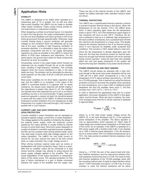
<strong>LM675</strong>Application HintsSTABILITYThe <strong>LM675</strong> is designed to be stable when operated at aclosed-loop gain of 10 or greater, but, as with any otherhigh-current amplifier, the <strong>LM675</strong> can be made to oscillateunder certain conditions. These usually involve printed circuitboard layout or output/input coupling.When designing a printed circuit board layout, it is importantto return the load ground, the output compensation ground,and the low level (feedback and input) grounds to the circuitboard ground point through separate paths. Otherwise, largecurrents flowing along a ground conductor will generatevoltages on the conductor which can effectively act as signalsat the input, resulting in high frequency oscillation orexcessive distortion. It is advisable to keep the output compensationcomponents and the 0.1 µF supply decouplingcapacitors as close as possible to the <strong>LM675</strong> to reduce theeffects of PCB trace resistance and inductance. For thesame reason, the ground return paths for these componentsshould be as short as possible.Occasionally, current in the output leads (which function asantennas) can be coupled through the air to the amplifierinput, resulting in high-frequency oscillation. This normallyhappens when the source impedance is high or the inputleads are long. The problem can be eliminated by placing asmall capacitor (on the order of 50 pF to 500 pF) across thecircuit input.Most power amplifiers do not drive highly capacitive loadswell, and the <strong>LM675</strong> is no exception. If the output of the<strong>LM675</strong> is connected directly to a capacitor with no seriesresistance, the square wave response will exhibit ringing ifthe capacitance is greater than about 0.1 µF. The amplifiercan typically drive load capacitances up to 2 µF or so withoutoscillating, but this is not recommended. If highly capacitiveloads are expected, a resistor (at least 1Ω) should be placedin series with the output of the <strong>LM675</strong>. A method commonlyemployed to protect amplifiers from low impedances at highfrequencies is to couple to the load through a 10Ω resistor inparallel with a5µHinductor.CURRENT LIMIT AND SAFE OPERATING AREA(SOA) PROTECTIONA power amplifier’s output transistors can be damaged byexcessive applied voltage, current flow, or power dissipation.The voltage applied to the amplifier is limited by the design ofthe external power supply, while the maximum currentpassed by the output devices is usually limited by internalcircuitry to some fixed value. Short-term power dissipation isusually not limited in monolithic operational power amplifiers,and this can be a problem when driving reactive loads, whichmay draw large currents while high voltages appear on theoutput transistors. The <strong>LM675</strong> not only limits current toaround 4A, but also reduces the value of the limit currentwhen an output transistor has a high voltage across it.When driving nonlinear reactive loads such as motors orloudspeakers with built-in protection relays, there is a possibilitythat an amplifier output will be connected to a loadwhose terminal voltage may attempt to swing beyond thepower supply voltages applied to the amplifier. This cancause degradation of the output transistors or catastrophicfailure of the whole circuit. The standard protection for thistype of failure mechanism is a pair of diodes connectedbetween the output of the amplifier and the supply rails.These are part of the internal circuitry of the <strong>LM675</strong>, andneedn’t be added externally when standard reactive loadsare driven.THERMAL PROTECTIONThe <strong>LM675</strong> has a sophisticated thermal protection schemeto prevent long-term thermal stress to the device. When thetemperature on the die reaches 170˚C, the <strong>LM675</strong> shutsdown. It starts operating again when the die temperaturedrops to about 145˚C, but if the temperature again begins torise, shutdown will occur at only 150˚C. Therefore, the deviceis allowed to heat up to a relatively high temperature ifthe fault condition is temporary, but a sustained fault will limitthe maximum die temperature to a lower value. This greatlyreduces the stresses imposed on the IC by thermal cycling,which in turn improves its reliability under sustained faultconditions. This circuitry is 100% tested without a heat sink.Since the die temperature is directly dependent upon theheat sink, the heat sink should be chosen for thermal resistancelow enough that thermal shutdown will not be reachedduring normal operaton. Using the best heat sink possiblewithin the cost and space constraints of the system willimprove the long-term reliability of any power semiconductor.POWER DISSIPATION AND HEAT SINKINGThe <strong>LM675</strong> should always be operated with a heat sink,even though at idle worst case power dissipation will be only1.8W (30 mA x 60V) which corresponds to a rise in dietemperature of 97˚C above ambient assuming θ jA = 54˚C/Wfor a TO-220 package. This in itself will not cause the thermalprotection circuitry to shut down the amplifier when operatingat room temperature, but a mere 0.9W of additional powerdissipation will shut the amplifier down since T J will thenincrease from 122˚C (97˚C + 25˚C) to 170˚C.In order to determine the appropriate heat sink for a givenapplication, the power dissipation of the <strong>LM675</strong> in that applicationmust be known. When the load is resistive, the maximumaverage power that the IC will be required to dissipateis approximately:where V S is the total power supply voltage across the<strong>LM675</strong>, R L is the load resistance and P Q is the quiescentpower dissipation of the amplifier. The above equation isonly an approximation which assumes an “ideal” class Boutput stage and constant power dissipation in all other partsof the circuit. As an example, if the <strong>LM675</strong> is operated on a50V power supply with a resistive load of 8Ω, it can developup to 19W of internal power dissipation. If the die temperatureis to remain below 150˚C for ambient temperatures up to70˚C, the total junction-to-ambient thermal resistance mustbe less thanUsing θ JC = 2˚C/W, the sum of the case-to-heat sink interfacethermal resistance and the heat-sink-to-ambient thermalresistance must be less than 2.2˚C/W. The case-to-heatsinkthermal resistance of the TO-220 package varies withthe mounting method used. A metal-to-metal interface will beabout 1˚C/W if lubricated, and about 1.2˚C/W if dry. If a micainsulator is used, the thermal resistance will be aboutwww.national.com 6