MSD Pulse Ignition for Harley-Davidson® - Zodiac
MSD Pulse Ignition for Harley-Davidson® - Zodiac
MSD Pulse Ignition for Harley-Davidson® - Zodiac

Create successful ePaper yourself
Turn your PDF publications into a flip-book with our unique Google optimized e-Paper software.
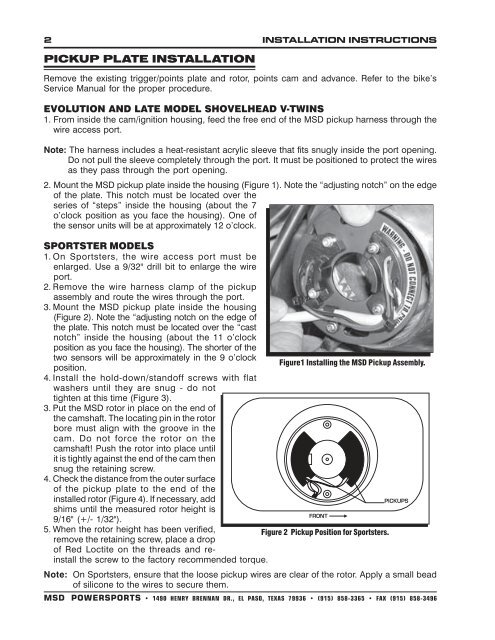
2 INSTALLATION INSTRUCTIONSPICKUP PLATE INSTALLATIONRemove the existing trigger/points plate and rotor, points cam and advance. Refer to the bike’sService Manual <strong>for</strong> the proper procedure.EVOLUTION AND LATE MODEL SHOVELHEAD V-TWINS1. From inside the cam/ignition housing, feed the free end of the <strong>MSD</strong> pickup harness through thewire access port.Note: The harness includes a heat-resistant acrylic sleeve that fits snugly inside the port opening.Do not pull the sleeve completely through the port. It must be positioned to protect the wiresas they pass through the port opening.2. Mount the <strong>MSD</strong> pickup plate inside the housing (Figure 1). Note the “adjusting notch” on the edgeof the plate. This notch must be located over theseries of “steps” inside the housing (about the 7o’clock position as you face the housing). One ofthe sensor units will be at approximately 12 o’clock.SPORTSTER MODELS1. On Sportsters, the wire access port must beenlarged. Use a 9/32" drill bit to enlarge the wireport.2. Remove the wire harness clamp of the pickupassembly and route the wires through the port.3. Mount the <strong>MSD</strong> pickup plate inside the housing(Figure 2). Note the “adjusting notch on the edge ofthe plate. This notch must be located over the “castnotch” inside the housing (about the 11 o’clockposition as you face the housing). The shorter of thetwo sensors will be approximately in the 9 o’clockFigure1 Installing the <strong>MSD</strong> Pickup Assembly.position.4. Install the hold-down/standoff screws with flatwashers until they are snug - do nottighten at this time (Figure 3).3. Put the <strong>MSD</strong> rotor in place on the end ofthe camshaft. The locating pin in the rotorbore must align with the groove in thecam. Do not <strong>for</strong>ce the rotor on thecamshaft! Push the rotor into place untilit is tightly against the end of the cam thensnug the retaining screw.4. Check the distance from the outer surfaceof the pickup plate to the end of theinstalled rotor (Figure 4). If necessary, addshims until the measured rotor height is9/16" (+/- 1/32").5. When the rotor height has been verified,Figure 2 Pickup Position <strong>for</strong> Sportsters.remove the retaining screw, place a dropof Red Loctite on the threads and reinstallthe screw to the factory recommended torque.Note: On Sportsters, ensure that the loose pickup wires are clear of the rotor. Apply a small beadof silicone to the wires to secure them.<strong>MSD</strong> POWERSPORTS • 1490 HENRY BRENNAN DR., EL PASO, TEXAS 79936 • (915) 858-3365 • FAX (915) 858-3496