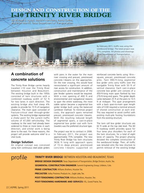
Design and Construction of thei-10 Trinity River <strong>Bridge</strong>by Michael D. Hyzak, David P. Hohmann, David Collins,and Brian Merrill, Texas Department of TransportationBy February 20<strong>11</strong>, traffic was using thewestbound bridge. <strong>The</strong> total project was75% complete. All photos and drawings:Texas Department of Transportation.A combination ofconcrete solutions<strong>The</strong> Trinity River <strong>Bridge</strong> carries heavilytraveled I-10 over the Trinity Riverbetween Houston and Beaumont.<strong>The</strong> existing bridge built in the 1950sconsisted of twin structures with acombined roadway width of 52 ftfor two lanes in each direction. <strong>The</strong>existing bridge also had steep 4%grades to provide for 73 ft of navigationclearance. <strong>The</strong> main span consisted offracture-critical steel through-girdersystems. <strong>The</strong> existing bridge representeda choke point for the current trafficvolume of 47,000 vehicles/day. <strong>The</strong>roadway to the west had already beenwidened to three or more lanes in eachdirection, and similar work is beingdone to the east. For these reasons, theproject will provide welcome relief to avital route.Design SolutionAn original concept was conceivedusing twin continuous steel plate girderswith piers in the water for the mainriver crossing and precast, prestressedconcrete I-beams on the approaches.On the river crossing, this would havenecessitated a significant amount ofriver access for construction. In addition,construction and maintenance of thepier fender systems would be required.With a river opening of 400 ft andenvironmental and navigational reasonsto span the entire waterway, the mostviable option became a segmental boxgirder bridge built using the balancedcantilever method. To minimize projectcosts, the approach spans remainedprecast, prestressed concrete I-beams.With the resulting reduced lengthof segmental spans, a cast-in-placesegmental box girder cast with formtravelers was the preferred structure type.<strong>The</strong> project was let to contract in 2006.In February 20<strong>11</strong>, the project wasapproximately 75% complete. <strong>The</strong> newTrinity River <strong>Bridge</strong> has twin structures3636 ft long with approach spansof 72-in.-deep precast, prestressedconcrete I-beams supported onreinforced concrete bents using 18-in.-square, precast, prestressed concretepiles. Twin 990-ft-long segmentalbox girder units carry traffic over thenavigable Trinity River with 50 ft ofvertical clearance. Each cast-in-placeconcrete box girder unit consists of a450-ft-long main span flanked by two270-ft-long end spans. <strong>The</strong> girder depthvaries between 25 ft at the piers to 10.5ft at midspan. This span arrangementwith a back span-to-main span lengthratio of 0.60 required a nominal amountof shored construction at each end.This was required to avoid conflict withexisting multi-pile footing foundationsfrom the existing structure.<strong>The</strong> twin cell box girder structures are62 ft wide at the top slab level. <strong>The</strong> 60ft roadway width provides space forfour lanes plus shoulders for each ofthe twin structures, for a total of eightlanes of capacity. <strong>The</strong> project phasingdictated the complete construction ofthe westbound bridge. <strong>The</strong>n, all trafficwas rerouted onto the new structure topermit removal of the existing bridgeprofiletrinity river <strong>Bridge</strong>/ between houston and beaumont, texasbridge design Engineer: Texas Department of Transportation, <strong>Bridge</strong> Division, Austin, Tex.segmental construction engineer: Summit Engineering Group, Littleton, Colo.prime contractor: Williams Brothers, Houston Tex.precaster: Valley Prestress Products Inc., Eagle Lake, Tex.post-tensioning contractor: Williams Brothers, Houston, Tex.post-tensioning hardware and services: VSL, Grand Prairie, Tex.22 | <strong>ASPIRE</strong>, <strong>Spring</strong> 20<strong>11</strong>
<strong>The</strong>re wereenvironmental andnavigational reasonsto span the entire400-ft-wide waterway.and construction of the eastboundbridge on the footprint of the formerbridge.<strong>The</strong> bridge features twin wall piers 42ft tall spaced 20 ft 0 in. out-to-out inthe longitudinal direction. Inclined piertable “A-frame” diaphragms 2 ft 9 in.thick, provide a requisite load path tothe top of the piers during the balancedcantilever construction. <strong>The</strong> piers havesufficient longitudinal flexibility to reducestresses from substructure restraint.Post-Tensioning Provisions<strong>The</strong> primary longitudinal post-tensioningincludes both cantilever and continuitytendons. To simplify construction,balanced cantilever segmental bridgesin Texas typically have each set ofcantilever tendons anchored withinthe top slab at the stiff web to flangejunction. Having the cantilever tendonanchorages at this location at thebulkhead face simplifies the travelerformwork in each typical segment.For each segment that is constructed,a single cantilever tendon containingthirteen 0.6-in.-diameter strands ineach web is stressed with the live endat the bulkhead face of the segmentpreviously cast and the dead end atthe free end of the last segment inthe opposite cantilever. As such, eachsegment has two anchorages in eachweb-to-flange joint. <strong>The</strong> end resultis a series of cantilever tendons thatincrease in number as the constructionprogresses with the maximum numberof tendons occurring at the pier tableand decreasing in each segment movingaway from the pier.Nearing closure of the 450-ft-long main span of the eastbound bridge. <strong>The</strong> girder is 10.5ft deep at midspan.SustainabilityIn Texas, alkali-silica reaction (ASR) is a very real problem that threatens the service lifeof concrete structures. Nearly 90% of the fine aggregate sources and over 60% of thecoarse aggregate sources have the potential to develop ASR. To combat this problem,TxDOT uses prescriptive specifications, based on over $8M in research, to mitigate ASR.<strong>The</strong>se specifications go hand-in-hand with the specifications used for high-performanceconcrete (HPC), which provides low-permeability concrete. <strong>The</strong> result is very high-qualityconcrete in all structural elements to ensure long-term performance.<strong>The</strong> prescriptive approach provides mix design options for contractors without the needfor additional material testing. TxDOT’s ASR mitigation options include the following:• various supplementary cementitious materials (fly ash, silica fume, or groundgranulatedblast-furnace slag)• lithium nitrate admixture• cement-only mixes with a limit on the total alkali content• custom mix designs based on aggregate test resultsIn addition to the ASR mitigation requirements, TxDOT also has the following specialrequirements for mass concrete used for the footings and twin-wall piers:• a maximum concrete temperature at time of placement of 75 °F• a maximum temperature differential between the central core and the exposedsurface of 35 °F during the heat dissipation period• a maximum core temperature of 160 °F during the heat dissipation period<strong>The</strong> contractor supplied several different concrete mixes for this project. <strong>The</strong> two mainconcrete mixes used for the segmental superstructure and the main pier substructurehad a Class F fly ash content of 25% and 30%, respectively, of the total cementitiousmaterials content to comply with TxDOT’s ASR mitigation requirements. Both mixesproduced concrete compressive strengths greater than 9000 psi during trial batchevaluations. <strong>The</strong> additional strength was not required by the design but was desired tokeep the casting and stressing operations on schedule. <strong>The</strong>se strengths were obtainedwith only 464 lb/yd 3 of cement and 155 lb/yd 3 of fly ash and a water- cementitiousmaterials ratio of 0.40.TWIN BRIDGES USING BOTH CAST-IN-PLACE CONCRETE BALANCED CANTILEVER SEGMENTAL MAIN SPANS ANDPRECAST, PRESTRESSED CONCRETE BEAM APPROACH SPANS / TEXAS DEPARTMENT OF TRANSPORTATION, OWNERconcrete supplier: ANT Enterprises, Baytown, Tex.form travelers: Mexpresa, Mexico City, Mexicobridge description: Twin bridges, 3636 ft long, 62 ft wide with a 990-ft-long, three-span, cast-in-place concrete segmental, variable-depth boxgirder unit (270, 450, and 270 ft span lengths) and 2646 ft of precast, prestressed concrete I-beam approach spans with AASHTO Type VI beams, up to150 ft long, and 18-in.-square precast, prestressed concrete piles<strong>Bridge</strong> Construction Cost: $67 million total project cost, $37.5 million for bridges ($164/ft 2 for segmental units and $53/ft 2 for I-beam approaches)<strong>ASPIRE</strong>, <strong>Spring</strong> 20<strong>11</strong> | 23