Product Name S320 GNSS Survey Receiver
Product Name S320 GNSS Survey Receiver
Product Name S320 GNSS Survey Receiver
- No tags were found...

You also want an ePaper? Increase the reach of your titles
YUMPU automatically turns print PDFs into web optimized ePapers that Google loves.
<strong>S320</strong> <strong>GNSS</strong> <strong>Product</strong> <strong>Survey</strong> <strong>Name</strong> <strong>Receiver</strong>Quick User Reference Guide GuidePart No.Part No. 875-0281-000 Rev C1
This device complies with Part 15 of the FCC Rules. Operation is subject to the following twoconditions: (1) this device may not cause harmful interference, and (2) this device must accept anyinterference received, including interference that may cause undesired operation.This equipment has been tested and found to comply with the limits for a Class B digital device,pursuant to Part 15 of FCC Rules. These limits are designed to provide reasonable protectionagainst harmful interference in a residential installation.This equipment generates, uses, and can radiate radio frequency energy. If not installed and usedin accordance with the instructions, it may cause harmful interference to radio communications.However, there is no guarantee that interference will not occur in a particular installation.If this equipment does cause harmful interference to radio or television reception, which can bedetermined by tuning the equipment off and on, the user is encouraged to try and correct theinterference by one or more of the following measures:• Reorient or relocate the receiving antenna.• Increase the distance between the equipment and the receiver.• Connect the equipment to an outlet on a circuit different from that to which the receiver isconnected.• Consult the dealer or an experienced radio/TV technician for help.Any changes or modifications not expressly approved by the party responsible for compliancecould void the user's authority to operate the equipment.Caution: Exposure to Radio Frequency Radiation.This device must not be co-located or operating in conjunction with any other antenna ortransmitter.Canada - Industry Canada (IC)This device complies with RSS 210 of Industry Canada. Operation is subject to the following twoconditions: (1) this device may not cause interference, and (2) this device must accept anyinterference, including interference that may cause undesired operation of this device.L ' utilisation de ce dispositif est autorisée seulement aux conditions suivantes: (1) il ne doit pasproduire d'interference et (2) l' utilisateur du dispositif doit étre prêt à accepter toute interferenceradioélectrique reçu, même si celle-ci est susceptible de compromettre le fonctionnement dudispositif.Caution: Exposure to Radio Frequency Radiation.The installer of this radio equipment must ensure that the antenna is located or pointed such that itdoes not emit RF field in excess of Health Canada limits for the general population; consult SafetyCode 6, obtainable from Health Canada's website http://www.hc-sc.gc.ca/rpb.Europe – Declaration of ConformityThis device is in compliance with the essential requirements of the R&TTE Directive 1999/5/EC.Copyright NoticeHemisphere GPS Precision GPS ApplicationsCopyright © Hemisphere GPS (2012). All rights reserved.No part of this manual may be reproduced, transmitted, transcribed, stored in a retrieval system ortranslated into any language or computer language, in any form or by any means, electronic,mechanical, magnetic, optical, chemical, manual or otherwise, without the prior writtenpermission of Hemisphere GPS.
TrademarksHemisphere GPS ® , the Hemisphere GPS logo, A100 TM , A20 TM , A21 TM , A220 TM , A221 TM , A30 TM ,A31 TM , A320 TM , A321 TM , A42 TM , A52 TM , AC110 TM , AerialACE TM , AgJunction ® , AirStar TM , AirTrac TM ,AutoMate TM , Bantam TM , BaseLineHD TM , BaseLineX TM , BEELINE ® , COAST TM , Contour Lock TM ,Crescent ® , Earthworks ® , Eclipse TM , e-Dif ® , eDrive ® , eDriveTC TM , eDriveVSi TM , eDriveX TM ,FliteTrac TM , G100 TM , G4 TM , GateMate TM , GPSteer TM , H102 TM , H320 TM , HQ TM , IntelliFlow ® ,IntelliGate TM , IntelliStar TM , IntelliTrac TM , Just Let Go TM , L-Dif TM , LiteStar II TM , LV101 TM , LX-1 TM , LX-2 TM ,M3 TM , MapStar ® , MBX-4 TM , miniEclipse TM , Outback TM , Outback 360 TM , Outback Guidance Center TM ,Outback Guidance ® , Outback Hitch TM , Outback S TM , Outback S2 TM , Outback S3 TM , Outback S-Lite TM ,Outback Sts TM , Outback Steering Guide TM , PocketMax PC TM , PocketMax TM , PocketMax3 TM , R100 TM ,R131 TM , R220 TM , R320 TM , <strong>S320</strong> TM , Satloc ® , the Satloc logo, SBX-4 TM , SLXMon TM , SureTrack ® , V101 TM ,V102 TM , V103 TM , V111 TM , V113 TM , VS101 TM , VS111 TM , Vector TM , X200 TM , X300 TM , XF1 TM , XF100 TM ,XF101 TM , and XF102 TM are proprietary trademarks of Hemisphere GPS. Other trademarks are theproperties of their respective owners.PatentsThe Outback S TM and S-Lite TM automated navigation and steering guide systems are covered byU.S. Patents No. 6,539,303 and No. 6,711,501. The Outback Hitch TM automated hitch control systemis covered by U.S. Patent No. 6,631,916. The Outback eDriveTC TM GPS assisted steering system iscovered by U.S. Patent No. 7,142,956. Hemisphere GPS products may be covered by one or moreof the following U.S. Patents:6,111,549 6,397,147 6,469,663 6,501,346 6,539,3036,549,091 6,631,916 6,711,501 6,744,404 6,865,4656,876,920 7,142,956 7,162,348 7,277,792 7,292,1857,292,186 7,373,231 7,400,956 7,400,294 7,388,5397,429,952 7,437,230 7,460,942Other U.S. and foreign patents pending.Notice to CustomersContact your local dealer for technical assistance. To find the authorized dealer near you:Hemisphere GPS4110 9th Street S.E.Calgary, Alberta, Canada T2G 3C4Phone: 403-259-3311Fax: 403-259-8866precision@hemispheregps.comwww.hemispheregps.comTechnical SupportIf you need to contact Hemisphere GPS Technical Support:8444 N 90th St, Suite 130Scottsdale, AZ 85258 USAPhone: (480) 348-9919Fax: (480) 348-6370techsupport@hemispheregps.comDocumentation FeedbackHemisphere GPS is committed to the quality and continuous improvement of our products andservices. We urge you to provide Hemisphere GPS with any feedback regarding this guide bywriting to the following email address: docfeedback@hemispheregps.com.
ContentsChapter 1 Introduction . . . . . . . . . . . . . . . . . . . . . . . . . . . . . . 1What’s In This Guide? . . . . . . . . . . . . . . . . . . . . . . . . . . . . . . . . . . . . 2<strong>Product</strong> Overview and Features . . . . . . . . . . . . . . . . . . . . . . . . . . . . 2What’s Included . . . . . . . . . . . . . . . . . . . . . . . . . . . . . . . . . . . . . . . . . 3Chapter 2 Installation . . . . . . . . . . . . . . . . . . . . . . . . . . . . . . . 5Ports and Connections . . . . . . . . . . . . . . . . . . . . . . . . . . . . . . . . . . . . 6Installing/Connecting the <strong>S320</strong> . . . . . . . . . . . . . . . . . . . . . . . . . . . . . 7Attaching the Antenna . . . . . . . . . . . . . . . . . . . . . . . . . . . . . . . . 7Connecting to a Power Source . . . . . . . . . . . . . . . . . . . . . . . . . 8Connecting to External Devices . . . . . . . . . . . . . . . . . . . . . . . . 9Setting Up the Unit . . . . . . . . . . . . . . . . . . . . . . . . . . . . . . . . . 10Chapter 3 Setup and Configuration . . . . . . . . . . . . . . . . . . . 11Control Panel Overview . . . . . . . . . . . . . . . . . . . . . . . . . . . . . . . . . . 12Powering the <strong>S320</strong> On and Off . . . . . . . . . . . . . . . . . . . . . . . . . . . . 14Modes of Operation . . . . . . . . . . . . . . . . . . . . . . . . . . . . . . . . . . . . . 14Displaying Current Module Status . . . . . . . . . . . . . . . . . . . . . . . . . 15Changing Module Status . . . . . . . . . . . . . . . . . . . . . . . . . . . . . . . . . 16Tilt Function Control . . . . . . . . . . . . . . . . . . . . . . . . . . . . . . . . . . . . 17Alarm/Buzzer . . . . . . . . . . . . . . . . . . . . . . . . . . . . . . . . . . . . . . . . . . 18Power and Battery Status/Charge . . . . . . . . . . . . . . . . . . . . . . . . . . 18Replacing/Swapping the Batteries . . . . . . . . . . . . . . . . . . . . . . . . . 19Removing/Inserting the SD Card / SIM Card . . . . . . . . . . . . . . . . . 20Bluetooth Communication . . . . . . . . . . . . . . . . . . . . . . . . . . . . . . . 21Upgrading <strong>S320</strong> Firmware . . . . . . . . . . . . . . . . . . . . . . . . . . . . . . . 22Upgrading <strong>S320</strong> Firmware via Serial Port . . . . . . . . . . . . . . . 22Upgrading <strong>S320</strong> Firmware via SD Card . . . . . . . . . . . . . . . . . 23GSM Functionality . . . . . . . . . . . . . . . . . . . . . . . . . . . . . . . . . . . . . . 24GSM Overview . . . . . . . . . . . . . . . . . . . . . . . . . . . . . . . . . . . . . 24GSM Modes . . . . . . . . . . . . . . . . . . . . . . . . . . . . . . . . . . . . . . . 24Configuring GSM for NTRIP . . . . . . . . . . . . . . . . . . . . . . . . . . 24Configuring SMS Messaging . . . . . . . . . . . . . . . . . . . . . . . . . 25Restoring Factory Defaults . . . . . . . . . . . . . . . . . . . . . . . . . . . . . . . 26Appendix A Troubleshooting . . . . . . . . . . . . . . . . . . . . . . . . . . 27Appendix B Technical Specifications . . . . . . . . . . . . . . . . . . . 29Index . . . . . . . . . . . . . . . . . . . . . . . . . . . . . . . . . . . . . . . . . . . . . . . 33End User License Agreement . . . . . . . . . . . . . . . . . . . . . . . . . . . . 35Warranty Notice . . . . . . . . . . . . . . . . . . . . . . . . . . . . . . . . . . . . . . 38<strong>S320</strong> User Guide v PN 875-0281-000 Rev C1
Chapter 1: IntroductionWhat’s In This Guide?<strong>Product</strong> Overview and FeaturesWhat’s Included<strong>S320</strong> User Guide 1 PN 875-0281-000 Rev C1
Chapter 1: IntroductionWhat’s In This Guide?This User Guide provides the following information to get you up and running quicklywith your <strong>S320</strong> <strong>GNSS</strong> <strong>Receiver</strong>:• This chapter briefly describes the <strong>S320</strong> and the parts in your <strong>S320</strong> kit.• Chapter 2, “Installation” provides a detailed overview of the physicalspecifications of the <strong>S320</strong> and includes such information as attaching theantenna and connecting to a power source.• Chapter 3, “Setup and Configuration” describes setting up and configuringthe <strong>S320</strong>, performing such basic tasks as using the control panel andswapping and charging the batteries, and GSM functionality regardingNTRIP and SMS.• Appendix A, “Troubleshooting” provides possible solutions for issues.• Appendix B, “Technical Specifications” lists the technical specifications ofthe <strong>S320</strong>.<strong>Product</strong> Overview and FeaturesThe <strong>S320</strong> is an integrated <strong>GNSS</strong> survey and mapping device for mobile data collectionproviding differential GPS (DGPS) accuracy in a rugged, all-in-one enclosure.Powered by Hemisphere GPS’ powerful dual constellation and dual frequencyEclipse II OEM board, the <strong>S320</strong> is suitable for GIS, mapping, land surveying, andconstruction with the following features:• Can be mounted on a range pole or tripod and carried by a single worker• Small and lightweight with good pole balance• Rugged construction• Hot-swappable batteries• Data storage• Fully functional without the need for external cables• Radio communicationsIf your <strong>S320</strong> is equipped with a 400 MHz radio you may berequired to obtain a valid radio license for your jurisdiction.<strong>S320</strong> User Guide 2 PN 875-0281-000 Rev C1
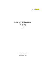
What’s IncludedChapter 1: IntroductionThe <strong>S320</strong> is available as a single unit or two units (base/rover setup). Figure 1-1 showsthe parts included in the single unit kit and Table 1-1 lists the parts included in bothkits.ABCDEFGHTable 1-1: <strong>S320</strong> parts listFigure 1-1: <strong>S320</strong> single unit kitItemItemQty(1 Unit)Qty(2 Units)Part NumberA <strong>S320</strong> 1 2 804-0079-000 (400 MHz)804-0090-000 (900 MHz)BCAntenna bracket (for upwardvertical antenna mounting)Antenna (model/type dependson region of use)1 2 602-1096-0001 2 150-0021-000 (400 MHz)150-0022-000 (900 MHz)D SD card 1 2 750-1099-000E Batteries (rechargeable 2 4 427-0043-000lithium-ion)F Power cable, external, 2-pincircular, 3 m (for base stationunit)N/A 1 054-0119-000G Battery charger 1 2 427-0044-000H Data cable, 9-pin to 9-pinserial, USB connector, andUSB receptacle1 2 051-0258-000NotshownNotshownPelican case 1 1 002-0083-000<strong>S320</strong> User Guide (thisdocument)1 1 875-0281-000<strong>S320</strong> User Guide 3 PN 875-0281-000 Rev C1
Chapter 2: InstallationPorts and ConnectionsInstalling/Connecting the <strong>S320</strong><strong>S320</strong> User Guide 5 PN 875-0281-000 Rev C1
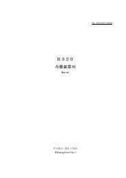
Chapter 2: InstallationPorts and ConnectionsAll connections and ports are located on the bottom of the unit, as shown inFigure 2-1. Table 2-1 provides additional information about each port/connection.Data portPower portAntenna portMounting holeSerial portTable 2-1: <strong>S320</strong> ports and connectionsFigure 2-1: <strong>S320</strong> ports and connectorsPortWhat to connectData port (ODU 9-pin) Data cable (Item H in Table 1-1 on page 3)Power port External power cable (Item F in Table 1-1 on page 3)Mounting holePole or tripod mountAntenna port External antenna (Item C in Table 1-1 on page 3)Serial port (DB9 female) External serial devices<strong>S320</strong> User Guide 6 PN 875-0281-000 Rev C1
Chapter 2: InstallationInstalling/Connecting the <strong>S320</strong>This section describes how to perform the following:• Attaching the antenna (see below)• Connecting to a power source (see page 8)• Setting up the unit (see page 10)Attaching the AntennaYou can attach the antenna in one of two ways:• Attaching the antenna directly to the antenna port on the bottom of the unitwith the antenna vertical and pointing downward (left photo in Figure 2-2)• Attaching the antenna bracket to the unit and then attaching the antenna tothe port at the end of the bracket with the antenna vertical and pointingupward (right photo in Figure 2-2)Antenna inserteddirectly into unitAntenna bracketBracket attachedto unit andantennainserted intobracketFigure 2-2: Antenna installation optionsTip: The antenna bracket offers an alternative solution in situations where installingthe antenna on the bottom of the unit may not provide suitable reception, such aswhere a small increase in antenna height has a noticeable effect on reception.To install the antenna directly into the unit:1. On the bottom of the unit remove the rubber cap covering the antenna port.2. Screw the antenna into the antenna port until snug. Do not overtighten.To install the antenna using the antenna bracket:1. Align the bracket to fit into therecessed area on the bottom ofthe unit (as shown at right).2. Using the two thumbscrews onthe bracket secure the bracket tothe unit. Do not overtighten.Antenna port3. Attach the bracket’s antenna cable to the unit’s antenna port.4. Screw the antenna into the bracket’s antenna port until snug. Do notovertighten.<strong>S320</strong> User Guide 7 PN 875-0281-000 Rev C1
Chapter 2: InstallationConnecting to a Power SourceThe <strong>S320</strong> power cable has a circular connector (2-pin ODU) at one end and twoclamps at the other end (red clamp positive and black clamp negative). Figure 2-3shows the power port pinout on the <strong>S320</strong> and Table 2-2 shows the pin descriptions.Table 2-2: Power port pinouts12Pin Description1 GND2 VCCFigure 2-3: Power port pinoutassignmentThe power supply is a nominal 12 VDC power supply and maximum currentconsumption is < 1 A at 12 VDC.Note: The power cable is included with the two-unit base/rover kit; it is not included inthe single-unit kit. See Table 1-1 on page 3 for information on the parts in each kit.Power portPower cableendFigure 2-4: Connecting the power cableNote: Applying external power does not charge the Li-ion batteries in the batterytrays. You must use a suitable battery charger to charge the batteries.To connect the power cable:• Line up the red dot on the power cable end with the red dot on the powerport and press into place.To disconnect the power cable:• Slide the cable collar (at the connector end) away from the unit and gentlyremove the cable.<strong>S320</strong> User Guide 8 PN 875-0281-000 Rev C1
Chapter 2: InstallationConnecting to External DevicesYou can connect the <strong>S320</strong> to external devices via the serial and data ports on thebottom of the unit.Serial Port Pinout SpecificationsFigure 2-5 shows the DB9 serial port (female) pinout, while Table 2-3 shows the serialport pinout specifications.Table 2-3: Serial port pinoutsPinDescription1 Not connected2 Transmit data port (TXD)3 Receive data port (RXD)4 Data terminal ready (DTR)Figure 2-5: Serial port pinoutassignment5 Signal ground (GND)6 Not connected7 Request to send (RTS)8 Not connected9 Timing output (1 PPS)Data Port Pinout SpecificationsFigure 2-6 shows the data port (ODU 9-pin) pinout, while Table 2-4 shows the data portpinout specifications.Table 2-4: Data port pinoutsPinDescription32184 65Figure 2-6: Data port pinoutassignment79 (center pin)1 USB host positive2 USB host VBS3 Ground4 Port B receive5 Port B transmit6 USB device source7 USB device negative8 USB host negative9 USB device positiveNote: When using the USB device end of the included data cable (Item H in Table 1-1on page 3) to connect to a USB port on an external device make sure the <strong>S320</strong> isalready powered on.<strong>S320</strong> User Guide 9 PN 875-0281-000 Rev C1
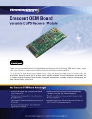
Chapter 2: InstallationTo connect the data cable:• Line up the red dot on the data cable end with the red dot on the data portand press into place.To disconnect the data cable:• Slide the cable collar (at the connector end) away from the unit and gentlyremove the cable.Setting Up the UnitFigure 2-7 shows a typical setup for both a base station unit and a rover unit (tripodand pole mount not included, data collector optional).The antenna in Figure 2-7 is connected to the bottom of the unit; you have the optionof attaching the antenna to the antenna bracket so the antenna faces upward. See“Attaching the Antenna” on page 7 for more information on attaching the antenna.Base setupRover setupFigure 2-7: Typical base and rover setup<strong>S320</strong> User Guide 10 PN 875-0281-000 Rev C1
Chapter 3: Setup and ConfigurationControl Panel OverviewPowering the <strong>S320</strong> On and OffModes of OperationDisplaying Current Module StatusChanging Module StatusTilt Function ControlAlarm/BuzzerPower and Battery Status/ChargeReplacing/Swapping the BatteriesRemoving/Inserting the SD Card / SIM CardBluetooth CommunicationUpgrading <strong>S320</strong> FirmwareGSM FunctionalityRestoring Factory Defaults<strong>S320</strong> User Guide 11 PN 875-0281-000 Rev C1
Chapter 3: Setup and ConfigurationThis chapter describes how to set up and configure the <strong>S320</strong> and includes thefollowing sections:• “Control Panel Overview” on page 12• “Powering the <strong>S320</strong> On and Off” on page 14• “Modes of Operation” on page 14• “Displaying Current Module Status” on page 15• “Changing Module Status” on page 16• “Tilt Function Control” on page 17• “Alarm/Buzzer” on page 18• “Power and Battery Status/Charge” on page 18• “Replacing/Swapping the Batteries” on page 19• “Removing/Inserting the SD Card / SIM Card” on page 20• “Bluetooth Communication” on page 21• “Upgrading <strong>S320</strong> Firmware” on page 22• “GSM Functionality” on page 24• “Restoring Factory Defaults” on page 26Control Panel OverviewYou operate the <strong>S320</strong> using the control panel shown in Figure 3-1.41 2 357 8A6BFigure 3-1: <strong>S320</strong> control panelThe <strong>S320</strong> beeps on any keypress. Table 3-1 describes the each button and LED on thecontrol panel.Table 3-1: <strong>S320</strong> control panel itemsDiagramItem<strong>Name</strong>DescriptionA Power button • If unit is Off, press and hold until unit powers up (untilyou hear one beep)• If unit is On, press and hold for approximately 3seconds (until you hear three beeps) to turn unit off<strong>S320</strong> User Guide 12 PN 875-0281-000 Rev C1
Chapter 3: Setup and ConfigurationTable 3-1: <strong>S320</strong> control panel items (continued)DiagramItem<strong>Name</strong>DescriptionBSelect button(for Bluetooth/UHF/GSM/SDmodules)1 UHF/GSM radiostatus LED2 GPS positionstatus LED3 DGPS positionstatus LED4 External powerstatus LED5 and 6 Battery statusLED7 Bluetooth statusLED8 SD loggingstatus LEDAllows you to review module status or change the status(power on/off) of a moduleSee “Displaying Current Module Status” on page 15 and“Changing Module Status” on page 16 for moreinformation on the Select button.• Off – UHF radio or GSM module is OFF; or no RTKposition computed• On (yellow) – floating point RTK position achieved• On (green) – fixed ambiguity RTK position achieved• Blink (green) – UHF radio or GSM moduletransmitting/receiving data• Pulse (red) – error condition with UHF radio or GSMmodule• Off – no position• On (yellow) – valid position• Blink (yellow) – operating as a base station andconverging on reference coordinates• Off – no differential corrections available• On (green) – differentially corrected positioncomputed• Off – external power not present• On (red) – external power present and in use• Off – battery not present• On (green) – battery charge full• On (yellow) – battery charge < 50%• On (red) – battery charge depleted• Blink – battery in use• Off – Bluetooth inactive• On (blue) – active Bluetooth connection• Blink (blue) - Bluetooth active and transmitting/receiving data• Off – SD card not inserted• On (yellow) – SD card inserted, not logging data• Blink (yellow) - SD card inserted and reading/writingdata to SD card• Pulse (yellow) at 5 Hz - SD card inserted and low freespace<strong>S320</strong> User Guide 13 PN 875-0281-000 Rev C1
Chapter 3: Setup and ConfigurationPowering the <strong>S320</strong> On and OffUse the Power button to power the <strong>S320</strong> on and off.Power buttonTo power on the <strong>S320</strong>:• Press and hold the Power button until the <strong>S320</strong> powers up (until you hearone beep).To power off the <strong>S320</strong>:• Press and hold the Power button for 3 seconds (until you hear three beeps).Note: When you power on the <strong>S320</strong> the LEDs go through a ‘heartbeat’ sequence (eachLED lights up in succession); during this time the modules power up and the devicesinitialize.Modes of OperationTable 3-2 lists the modes of operation for the <strong>S320</strong>.Table 3-2: <strong>S320</strong> modes of operationMode DescriptionEclipseSoftwareGSMModeUHFModeBluetooth ModeL-band rover SBASRTKB OFF OFF ON or OFFSingle point datacollection for postprocessingSBASRTKB OFF OFF ON or OFFRTK Base Station SBASRTKB OFF ON ON or OFFRTK Rover - UHF RTK OFF ON ON or OFFRTK Rover - GSM RTK ON OFF ON or OFFRTK Rover - Externalcorrections via BluetoothRTK Rover - External serialcorrectionsRTK OFF OFF ON (both ports - onemonitor, one diff input)RTK OFF OFF ON or OFFYou can quickly review and/or change the GSM, UHF, and Bluetooth states using thePower and Select buttons.<strong>S320</strong> User Guide 14 PN 875-0281-000 Rev C1
Displaying Current Module StatusChapter 3: Setup and ConfigurationThe <strong>S320</strong> allows you to quickly review the status of each module (UHF/GSM, mode ofoperation, Bluetooth, and SD card logging).To display current module status:• Press the Select button.The external power status LED is red (the unit is displaying its current status)and the LED of each module will be either OFF (LED not illuminated, modulepowered off) or ON (LED illuminated, module powered on).Table 3-3 illustrates the colors of the LEDs for each module.Table 3-3: Module status LED color descriptionsLED LED Color <strong>S320</strong> OperationUHF/GSM Off UHF radio and GSMmodule both offGreenUHF radio onYellowGSM module onGPS and DGPSposition indicatorsOff (both)GPS YellowDGPS NoneGPS NoneDGPS GreenGPS YellowDGPS GreenL-bandRTK roverRTK basee-DifBluetooth Off Bluetooth offBlueBluetooth onSD card logging Off SD card logging offYellowSD card logging onFor example, in the figure below the UHF radio is on, the unit is in RTK Rover mode,Bluetooth is active, and SD card logging is on.<strong>S320</strong> User Guide 15 PN 875-0281-000 Rev C1
Chapter 3: Setup and ConfigurationChanging Module StatusYou change module status by using the Select button to select the module and thePower button to change the module status.To change module status:1. Press the Select button to display the status of all modules (if the LED is on,the module is on; if the LED is off, the module is off).2. Press the Select button again to select the first module (UHF/GSM).Note: When you press the Select button the LED (for the module status youare changing) remains illuminated for 5 seconds, during which time you can usethe Power button to change the module status in step 3.3. If you want to change the current module’s status, press the Power button.Note: When you press the Power button the LED (for the module status youare changing) blinks 5 times to indicate a status change.4. Repeat steps 2 and 3 for each remaining module (if desired).After a status change, the function of the LEDs return to normal mode.<strong>S320</strong> User Guide 16 PN 875-0281-000 Rev C1
Chapter 3: Setup and ConfigurationTilt Function ControlThe <strong>S320</strong> includes tilt control functionality that allows you to level your unit using fiveof the LED indicators. When you activate tilt control you see the changes to the angleof the antenna in real time (similar to a level).To activate tilt control functionality:• Press the Power button and the Select button at the same time. The tilt ofthe unit is displayed for a period of 1 minute or until you deactivate tiltcontrol functionality.To deactivate tilt control functionality (return to normal operation):• Press the Power button and the Select button at the same time.When tilt control functionality is activated:• X-axis tilt is displayed alongthree horizontal LEDs• Y-axis tilt is displayed alongthree vertical LEDs• Each LED shows a 0.5° tilt(user-configurable)X-axis tilt LEDs Y-axis tilt LEDsTable 3-4 illustrates the colors of theLEDs depending on the tilt direction of the unit. These LED colors only apply if youhave activated tilt control.Table 3-4: Tilt control LED colorsLED ColorsMeaningMiddle (right battery) LED isgreenUnit is levelLeft LED is greenRight LED is greenUnit is off level to the leftUnit is off level to the rightLeft LED is green and middle(right battery) LED is redRight LED is green andmiddle (right battery) LED isredTop LED is redBottom LED is redUnit is off level to the left by morethan twice the configurable amountUnit is off level to the right by morethan twice the configurable amountUnit is tilted backwardUnit is tilted forward<strong>S320</strong> User Guide 17 PN 875-0281-000 Rev C1
Chapter 3: Setup and ConfigurationAlarm/BuzzerThe <strong>S320</strong> beeps under the following conditions:• Whenever you press a button• Position is lost• Differential position is achieved• Bluetooth device is connected/disconnected• Low memory for data storage (SD card almost full)• Both batteries are very lowIf an alarm is sounding, you can silence the alarm by pressing the Power button.Power and Battery Status/ChargeLEDs on the console provide power and battery status/charge information based onthe color of the LEDs. For example, Figure 3-2 indicates there is no external power, theright battery is fully charged, and the left battery is not present (not in the unit).Figure 3-2: No external power, right battery full, left battery not presentTable 3-5 describes what the power/battery LED colors indicate. The <strong>S320</strong> prioritizespower usage to use external power when available, regardless of the status of theinternal batteries.Table 3-5: Power/battery LED color descriptionsLED LED Color MeaningPower Off No external powerRedExternal power present and in useLeft batteryOffBattery not presentRight batteryRedYellowBattery very low or fully discharged (unit willbeep when both batteries are very low)Battery less than 1/2 chargedGreenBattery fully chargedNote: A blinking battery light indicates that battery is in use.<strong>S320</strong> User Guide 18 PN 875-0281-000 Rev C1
Replacing/Swapping the BatteriesChapter 3: Setup and ConfigurationIf the <strong>S320</strong> is off you can replace both batteries at one time. If you want to keep theunit running while replacing the batteries you must replace them one at a time toensure the unit is receiving power from at least one battery.To replace/swap a battery:1. For the battery you want to replace remove the battery tray by squeezing thethumb lever and pulling.Thumb lever2. Remove the battery from the tray.3. Insert the new battery.Note: When inserting the battery make sure the end with the leads (on top)points away from the tray.Battery leads4. Replace the tray, making sure the tray snaps into place.<strong>S320</strong> User Guide 19 PN 875-0281-000 Rev C1
Chapter 3: Setup and ConfigurationRemoving/Inserting the SD Card / SIM CardCaution: Use electrostatic discharge (ESD) protection, such as by wearing anESD strap that is attached to an earth ground, before inserting or removingthe SIM card on the <strong>S320</strong>. If an ESD strap is not available then touch a metalobject prior to accessing the SIM card holder.The SD card and the SIM card are only accessible by first removing the appropriatebattery tray, where the:• Left tray is labeled “SD”• Right tray is labeled “SIM”To remove the SD card or SIM card:1. Remove the appropriate battery tray.2. Place the <strong>S320</strong> upside down (on its top) to get a better view of the card.notch endgoes in firstnotch endgoes in firstSIMcardSDcard3. Gently push the card in; it will then snap back and slightly out.Note: When you insert either card make sure the contacts on the card arefacing the top of the unit and the side of the card with the notch goes in first(see figure in step 2 above).4. Remove the card.To insert the SD card or SIM card:1. Place the card in its appropriate card slot.2. Gently push the card in until it clicks.3. Replace the battery tray.<strong>S320</strong> User Guide 20 PN 875-0281-000 Rev C1
Chapter 3: Setup and ConfigurationBluetooth CommunicationIf you have a Bluetooth-enabled device, such as a data collector, you can wirelesslycommunicate with the <strong>S320</strong>.When you attempt to connect the <strong>S320</strong> to a Bluetooth-enabled device, such as ahandheld data collector, the following <strong>S320</strong> Bluetooth information appears on thedevice:HGPS <strong>S320</strong> XXXXXXwhere “XXXXXX” is the Eclipse board serial numberTo complete the connection you must use the correct PIN/Passkey, which is 0000.Table 3-6 describes the Bluetooth status LED options.Table 3-6: Bluetooth LED statusLED ColorsOffMeaningBluetooth inactiveBlueActive Bluetooth connectionBlue blinking/pulsingActive Bluetooth connection andtransmitting/receiving data<strong>S320</strong> User Guide 21 PN 875-0281-000 Rev C1
Chapter 3: Setup and ConfigurationUpgrading <strong>S320</strong> FirmwareYou can upgrade <strong>S320</strong> firmware via serial port or SD card.Upgrading <strong>S320</strong> Firmware via Serial PortBefore you upgrade verify the <strong>S320</strong> is powered off and, if you will not be usingexternal power, both Li-ion batteries are fully charged and inserted into the <strong>S320</strong>.1. Download the Autoloader_<strong>S320</strong> executable (.exe file) for the most recentversion from the Hemisphere GPS website at www.hemispheregps.com andsave it to your PC.2. Using the data cable included in your <strong>S320</strong> kit, connect the DB9 serial portend of the cable to your PC and connect the other end of the cable to thedata port on the <strong>S320</strong> (see below):To <strong>S320</strong> data portTo PC serial portNot used in thisprocedure3. Power on the <strong>S320</strong>.4. Double-click the Autoloader_<strong>S320</strong> file you download in step 1 to start theAutoloader program.5. In the Com Port drop-down box select the appropriate COM port on your PCand then click Load.Status areashows theload progress<strong>S320</strong> User Guide 22 PN 875-0281-000 Rev C1
Chapter 3: Setup and ConfigurationThe Status area shows the load progress. When loading is complete thefollowing message appears.6. Click OK.7. In the Autoloader window click Exit.Upgrading <strong>S320</strong> Firmware via SD CardBefore you upgrade verify the <strong>S320</strong> is powered off and, if you will not be usingexternal power, both Li-ion batteries are fully charged and inserted into the <strong>S320</strong>.1. Download the <strong>S320</strong>_Upgrade.zip file from the Hemisphere GPS website atwww.hemispheregps.com and save it to your PC.2. Unzip the file and extract the contents to the root folder of the SD card,ensuring the same folder structure of the contents on the SD card.3. Remove the SD card from the PC.4. If necessary remove the left battery tray from the <strong>S320</strong> (the left tray islabeled SD).5. Insert the SD card into the <strong>S320</strong> (see “Removing/Inserting the SD Card / SIMCard” on page 20).6. Replace the battery tray.7. Power on the <strong>S320</strong>.a. The LEDs cycle from left to right while the receiver is reading theupgrade file.b. After the file has passed all internal verifications, the bottom batteryLED illuminates green.c. The LEDs cycle from left to right while the file is copied.d. All the LEDs flash quickly to indicate the new firmware file is beingcommitted to the receiver.e. After committing the new file to internal memory, the LEDs cycle fromleft to right one more time before resetting the receiver and returning tothe heartbeat sequence.The upgrade is complete.<strong>S320</strong> User Guide 23 PN 875-0281-000 Rev C1
Chapter 3: Setup and ConfigurationGSM FunctionalityThis section provides advanced GSM information that requires connection to a PCrunning either Hemisphere GPS’ PocketMax utility or a terminal program such asHyperTerminal.This section covers the following topics:• GSM overview• GSM modes• Configuring GSM for NTRIP• SMS messagingGSM OverviewGlobal System for Mobile Communications (GSM) is a network technology for mobilephone communications. The GSM modem in the <strong>S320</strong> is what allows you to connectto a GSM carrier.The Access Point <strong>Name</strong> (APN) is a protocol that allows the <strong>S320</strong> to access the internetusing the mobile phone network. It is a configurable network identifier used whenconnecting to a GSM carrier. The default APNCFG value is "internet.com". The specificAPN required by the <strong>S320</strong> depends on your mobile carrier. Check with your mobileprovider for details.GSM ModesThe GSM module operates in four modes:• IDLE - Default mode for the module. In this state, the GSM module onlyattempts to register on the network.• DIRECT IP - For users who have direct access to a server providingdifferential corrections.• LINK - For users to establish a link between two <strong>S320</strong> modules directly,where the BASE has a dynamic IP address. You should only use this modeon the rover in a base station / rover setup (use IDLE mode for the basestation).• NTRIP - Used to provide differential correction information to the GPSreceiver.Configuring GSM for NTRIPNTRIP (Networked Transport of RTCM via Internet Protocol) is the protocol fortransmitting <strong>GNSS</strong> data over the internet.Note: To configure NTRIP you must connect the <strong>S320</strong> to a PC running eitherHemisphere GPS’ PocketMax utility or a terminal program such as HyperTerminal.To configure NTRIP send the following command:$GSMCFG,NTRIP,[remote host name or IP address],[port number],[mountpoint name],[[username],[password]]where,<strong>S320</strong> User Guide 24 PN 875-0281-000 Rev C1
Chapter 3: Setup and Configuration• Remote host name - server name (such as www.igs-ip.net) or an IP address• Mount point name - caster stream name from NTRIP Caster Source Table(you can download a sample source table from http://www.igs-ip.net:2101/).If you leave this field blank, the <strong>S320</strong> will fetch the caster source table andselect the mount point closest to its current position.• User name and password - authentication with a user name and password isrequired for most NTRIP casters. You can leave both blank to specify that noauthentication is required. The user name and password are case sensitive.For example, to connect to the CALG0 stream on igs-ip.net send the followingcommand:$GSMCFG,NRTIP,www.igs-ip.net,2101,CALG0,Usrnam,passwdConfiguring SMS MessagingThe <strong>S320</strong> supports Short Message Service (SMS) configuration and event updates forboth base and rover operations.When using SMS messaging keep the following in mind:• The GSM module must be powered on for SMS commands to workcorrectly.• You can send SMS messages to the <strong>S320</strong> from up to three numbers andthese numbers must be added to the <strong>S320</strong> approved numbers list.• By default the approved numbers list is comprised of the first three entries inthe SIM card address book. However, for a typical data-only SIM card, theaddress book of the SIM card will be empty.• Use the appropriate country code (the following procedures use the “+1”country code for USA/Canada).Adding or Overwriting a Number on the Approved Numbers ListYou can add a number to an empty slot or overwrite an existing number using thefollowing command:$JSMS,CONFIG,[slot number 1/2/3],[number],[name],[status messagesON | OFF]For example, to add “Service” (USA phone number 999-555-1212) to slot 1 with statusmessages OFF (or to replace the current number in slot 1) send the followingcommand:$JSMS,CONFIG,1,+19995551212,Service,OFFThe status message state (ON or OFF) allows the <strong>S320</strong> to send an SMS message backto the number to report information and events on the operation of the unit.Displaying the Current List of Approved NumbersTo display the current list of approved numbers send the following command:$JSMS,CONFIGThe reply below contains all the information on the configured numbers and mayinclude SIM card address book defaults that you can overwrite with your owninformation.$>JSMS,CONFIG,1,1,+19995551212,Service,OFF<strong>S320</strong> User Guide 25 PN 875-0281-000 Rev C1
Chapter 3: Setup and ConfigurationThe format of the reply is:$>JSMS,CONFIG,[number of approved numbers],[slot number 1/2/3],[number],[name],[status messages ON | OFF]Note: The reply contains one line for each number. For example, if there are twoapproved numbers then the reply will contain a “$>JSMS,CONFIG” line for eachnumber.Deleting a Number from the Approved Numbers ListTo delete a number from the approved numbers list, send the following command:$JSMS,CONFIG,[1/2/3 or keyword ALL],DELETEFor example, to delete the number in slot 2 send the following command:$JSMS,CONFIG,2,DELETEAnd to delete all numbers from the list, send the following command:$JSMS,CONFIG,ALL,DELETESending an SMS Message to an Approved NumberTo send an SMS message to an approved number, send the following command:$JSMS,SEND,[name or phone number or slot number],[message]For example, to send a “This is a test” message to Customer Support (USA phonenumber 480-348-9919, slot number 2) you can send any of the following commands:$JSMS,SEND,SERVICE,This is a test$JSMS,SEND,+14803489919,This is a test$JSMS,SEND,2,This is a testRestoring Factory DefaultsIf you need to restore your factory defaults for any reason you can do this via theControl panel.To restore factory defaults:• Press and hold the Power button for 10 to 20 seconds and release it whilethe GPS status and DGPS status LEDs are blinking.<strong>S320</strong> User Guide 26 PN 875-0281-000 Rev C1
Appendix A: Troubleshooting<strong>S320</strong> User Guide 27 PN 875-0281-000 Rev C1
Appendix A: TroubleshootingTable A-1 provides troubleshooting tips for the <strong>S320</strong>.Table A-1: <strong>S320</strong> troubleshootingIssue<strong>Receiver</strong> fails topowerNo data logged1. Nocommunication2. No valid dataRandom binary datafrom Eclipse OEMboardPossible Resolution• External power is low• Check charge on external battery and the fuse on the powercable, if applicable• Internal power: Check charge on internal batteries• Check all power cables and pins• Try other batteries or cables• Make sure to hold the power button down for a minimum ofone full second to turn on• Ensure batteries are installed with contacts pointed in thecorrect direction• (1) Check receiver power status• (2) Verify it is locked to a valid DGPS signal• (2) Verify that it is locked to 4 or more GPS satellites• (2) Check integrity and connectivity of power and data cableconnections• Verify that the baud rate settings match• If trying to connect over Bluetooth, ensure Bluetooth moduleis powered ON and device is paired prior to opening the port• Verify the RCTM or the Bin messages are not beingaccidentally output (send a $JSHOW command)• Verify the baud rate settings match• Potentially, the volume of data requested to be output couldbe higher than the current baud rate supports. Try using ahigher baud rate for communications.No <strong>GNSS</strong> position • Verify the antenna’s view of the sky, especially toward SBASsatellites, south in the northern hemisphere• Verify the bit error rate (BER) and lock status of SBAS satellites(this can often be done on the receiving device or by usingSLXMon - monitor BER value)• Verify the proper application is running on the Eclipse(SBASRTKB)• Set the satellite selection to automatic mode $JFREQ,AUTO• Set the differential mode to $JDIFF,WAAS• Ensure there is SBAS coverage in your areaNo DGPS position inexternal RTCM mode• Verify the baud rate of the RTCM input port matches the baudrate of the external source• Verify the pinout between the RTCM source and the RTCMinput port (the “ground” pin and pinout must be connected,and the “transmit” from the source must connect to the“receiver” of the RTCM input port)Non-DGPS output • If using RTK, ensure receiver is properly authorized for RTK bysending a $JI command or a $JK command<strong>S320</strong> User Guide 28 PN 875-0281-000 Rev C1
Appendix B: Technical Specifications<strong>S320</strong> User Guide 29 PN 875-0281-000 Rev C1
Appendix B: Technical SpecificationsThe following tables provide information on the technical specifications of the <strong>S320</strong>.Table B-1: <strong>GNSS</strong> receiver specificationsItem<strong>Receiver</strong> typeChannelsPositioning modesRTK formatsUpdate rate / recording intervalStatic performanceCold start timeSpecificationDual frequency <strong>GNSS</strong>All in viewL1CA GPSL1P GPSL2P GPSL2C GPSL1 GLONASSL2 GLONASS3 SBAS or 3 additional L1CA GPS1 L-bandNote: Some options may require a subscription.RTK, ROX, SBAS, External RTCM, Autonomous,L-band DGPS service, L-band high precision services,L-band high precision service with GLONASSCMR, CMR+ 1 , RTCM3Selectable from 1, 2, 4, 5, 10 Hz(20 Hz available)Horizontal 5 mm + 0.5 ppm< 60 s typical (no almanac or RTC)Table B-2: Performance specificationsItemStatic performanceDGPS performanceSpecificationHorizontal 5 mm + 0.5 ppm< 0.3 mTable B-3: Horizontal accuracy specificationsItemDescriptionRMS (67%) 2DRMS (95%)RTK 2,3 10 mm + 1 ppm 20 mm + 2 ppmL-band high precision services 2,4 0.1 m 0.2 mSBAS (WAAS) 2 0.3 m 0.6 mAutonomous, no SA 2 1.2 m 2.5 mTable B-4: Communication and port specificationsItemBluetoothDescriptionDual port<strong>S320</strong> User Guide 30 PN 875-0281-000 Rev C1
Appendix B: Technical SpecificationsTable B-4: Communication and port specificationsItemDescriptionRadio GSM optionsIntegrated1 x GSM/GPRS1 x SS (900 MHz or UHF range: 400 MHz)CDMA capableBaud rates 4800 - 115200Serial ports1 x RS-232 (9-pin circular, multi use)1 x RS-232 (9-pin DSUB)Power port1 x Power input (2-pin circular)USB1 USB Host1 USB Device (9-pin circular)Table B-5: Environmental specificationsItemOperating temperatureStorage temperatureHumidityEnclosureShockSpecification-30°C to +65°C (-22°F to +149°F)-40°C to +85°C (-40°F to +185°F)Up to 100% condensingIP67EP455, 2 m (6.56 ft) pole dropTable B-6: Power specificationsItemBatteryExternal voltageInternal radio powerSpecification2 x lithium ion, 2.6 Ah each, 5.2 Ah total, 7.2 V9 to 20 VDC1 WattTable B-7: Mechanical specificationsItemDimensionsWeightMaterialDescription114 H x 197 D mm(4.49 H x 7.76 D in)1.51 kg (3.33 lb)Plastic1 Receive only, does not transmit this format.2 Depends on multipath environment, number of satellites in view, satellite geometry,and ionospheric activity.3 Depends also on baseline length.4 Requires an L-band subscription.<strong>S320</strong> User Guide 31 PN 875-0281-000 Rev C1
IndexAactivating tilt control 17adding SMS number to approved list 25alarm 18antenna 3attaching 7bracket 3port 6attaching the antenna 7Autoloader 22Bbase station setup 10batteries 3replacing 19swapping 19battery charger 3battery status 18Battery status LED 13Bluetooth 21device name 21passkey 21status LED 13bracket (antenna) 3buzzer 18Ccablesdata 3, 22power 3, 8case 3changingmodule status 16communicationBluetooth 21specifications 30configuringGSM for NTRIP 24SMS messaging 25connecting to a power source 8connections 6mounting hole 6control paneloverview 12power button 12Select button 13Ddata cable 3, 22data port 6deactivating tilt control 17deleting SMS number from approved list26device name for Bluetooth 21DGPS position status LED 13displayingcurrent module status 15SMS approved numbers 25EEclipse II 2environmental specifications 31External power status LED 13Ffeatures 2firmwareupgrading 22G<strong>GNSS</strong> receiver specifications 30GPS position status LED 13GSMconfiguring for NTRIP 24functionality 24modes 24overview 24Hhorizontal accuracy specifications 30Iinserting SD/SIM card 20installation overview 7LL-band rover mode 14LEDBattery 13Bluetooth 13DGPS position 13External power 13GPS position 13SD logging 13UHF/GSM 13Mmechanical specifications 31modes<strong>S320</strong> User Guide 33 PN 875-0281-000 Rev C1
IndexGSM 24operation 14module statuschanging 16displaying 15mounting hole 6NNTRIP 24Ooperation modes 14overview 2overwriting SMS number on approved list25Pparts list 3passkey 21pelican case 3performance specifications 30port specifications 30ports 6antenna 6data 6power 6serial 6Power button 12power cable 3, 8power port 6power source connection 8power specifications 31power status 18power supply 8powering the unit on and off 14product overview 2Rremoving SD/SIM card 20replacing batteries 19rover setup 10RTK base station mode 14RTK rover (external corrections via Bluetooth)mode 14RTK rover (external corrections via serial)mode 14RTK rover (GSM) mode 14RTK rover (UHF) mode 14SSD card 3inserting 20removing 20upgrading firmware 23SD logging status LED 13Select button 13sending SMS message to approved number26serial port 6upgrading firmware 22setting up the <strong>S320</strong> 10SIM cardinserting 20removing 20Single point mode 14SMS messaging 25adding a number to approved list 25deleting number from approved list26displaying approved numbers 25overwriting a number on approved list25sending message to approved number26status LEDBattery 13Bluetooth 13DGPS position 13External power 13GPS position 13SD logging 13UHF/GSM 13swapping batteries 19Ttechnical specificationscommunication 30environmental 31<strong>GNSS</strong> receiver 30horizontal accuracy 30mechanical 31performance 30port 30power 31tilt control 17troubleshooting 28UUHF/GSM status LED 13upgrading firmwareoverview 22via SD card 23via serial port 22Wwhat’s included 3<strong>S320</strong> User Guide 34 PN 875-0281-000 Rev C1
End User License AgreementIMPORTANT - This is an agreement (the "Agreement") between you, the end purchaser ("Licensee") and HemisphereGPS Inc. ("Hemisphere") which permits Licensee to use the Hemisphere software (the "Software") that accompanies thisAgreement. This Software may be licensed on a standalone basis or may be embedded in a <strong>Product</strong>. Please read andensure that you understand this Agreement before installing or using the Software Update or using a <strong>Product</strong>.In this agreement any product that has Software embedded in it at the time of sale to the Licensee shall be referred to as a"<strong>Product</strong>". As well, in this Agreement, the use of a <strong>Product</strong> shall be deemed to be use of the Software which is embeddedin the <strong>Product</strong>.BY INSTALLING OR USING THE SOFTWARE UPDATE OR THE PRODUCT, LICENSEE THEREBY AGREES TO BE LEGALLYBOUND BY THE TERMS OF THIS AGREEMENT. IF YOU DO NOT AGREE TO THESE TERMS, (I) DO NOT INSTALL OR USETHE SOFTWARE, AND (II) IF YOU ARE INSTALLING AN UPDATE TO THE SOFTWARE, DO NOT INSTALL THE UPDATE ANDPROMPTLY DESTROY IT.HEMISPHERE PROVIDES LIMITED WARRANTIES IN RELATION TO THE SOFTWARE. AS WELL, THOSE WHO USE THEEMBEDDED SOFTWARE DO SO AT THEIR OWN RISK. YOU SHOULD UNDERSTAND THE IMPORTANCE OF THESE ANDOTHER LIMITATIONS SET OUT IN THIS AGREEMENT BEFORE INSTALLING OR USING THE SOFTWARE OR THE PRODUCT.1. LICENSE. Hemisphere hereby grants to Licensee a non-transferable and non-exclusive license to use the Softwareas embedded in a <strong>Product</strong> and all Updates (collectively the "Software"), solely in binary executable form.2. RESTRICTIONS ON USE. Licensee agrees that Licensee and its employees will not directly or indirectly, in anymanner whatsoever:a. install or use more copies of the Software than the number of copies that have been licensed;b. use or install the Software in connection with any product other than the <strong>Product</strong> the Software was intendedto be used or installed on as set out in the documentation that accompanies the Software.c. copy any of the Software or any written materials for any purpose except as part of Licensee's normal backupprocesses;d. modify or create derivative works based on the Software;e. sub-license, rent, lease, loan or distribute the Software;f. permit any third party to use the Software;g. use or operate <strong>Product</strong> for the benefit of any third party in any type of service outsourcing, application service,provider service or service bureau capacity;h. reverse engineer, decompile or disassemble the Software or otherwise reduce it to a human perceivable form;i. Assign this Agreement or sell or otherwise transfer the Software to any other party except as part of the saleor transfer of the whole <strong>Product</strong>.3. UPDATES. At Hemisphere's discretion Hemisphere may make Updates available to Licensee. An update("Update") means any update to the Software that is made available to Licensee including error corrections,enhancements and other modifications. Licensee may access, download and install Updates during the WarrantyPeriod only. All Updates that Licensee downloads, installs or uses shall be deemed to be Software and subject to thisAgreement. Hemisphere reserves the right to modify the <strong>Product</strong> without any obligation to notify, supply or installany improvements or alterations to existing Software.4. SUPPORT. Hemisphere may make available directly or through its authorized dealers telephone and email supportfor the Software. Contact Hemisphere to find the authorized dealer near you. As well, Hemisphere may makeavailable user and technical documentation regarding the Software. Hemisphere reserves the right to reduce andlimit access to such support at any time.5. BACKUPS AND RECOVERY. Licensee shall back-up all data used, created or stored by the Software on a regularbasis as necessary to enable proper recovery of the data and related systems and processes in the event of amalfunction in the Software or any loss or corruption of data caused by the Software. Licensee shall assume all risksof loss or damage for any failure to comply with the foregoing.6. OWNERSHIP. Hemisphere and its suppliers own all rights, title and interest in and to the Software and relatedmaterials, including all intellectual property rights. The Software is licensed to Licensee, not sold.7. TRADEMARKS. "Hemisphere GPS", "Outback Guidance", "BEELINE", "Crescent", "Eclipse" and the associated logosare trademarks of Hemisphere. Other trademarks are the property of their respective owners. Licensee may not useany of these trademarks without the consent of their respective owners.8. LIMITED WARRANTY. Hemisphere warrants solely to the Licensee, subject to the exclusions and procedures setforth herein below, that for a period of one (1) year from the original date of purchase of the <strong>Product</strong> in which it isembedded (the "Warranty Period"), the Software, under normal use and maintenance, will conform in all materialrespects to the documentation provided with the Software and any media will be free of defects in materials andworkmanship. For any Update, Hemisphere warrants, for 90 days from performance or delivery, or for the balance ofthe original Warranty Period, whichever is greater, that the Update, under normal use and maintenance, willconform in all material respects to the documentation provided with the Update and any media will be free ofdefects in materials and workmanship. Notwithstanding the foregoing, Hemisphere does not warrant that theSoftware will meet Licensee's requirements or that its operation will be error free.9. WARRANTY EXCLUSIONS. The warranty set forth in Section (8) will not apply to any deficiencies caused by (a)the <strong>Product</strong> not being used as described in the documentation supplied to Licensee, (b) the Software having beenaltered, modified or converted in any way by anyone other than Hemisphere approved by Hemisphere, (c) anymalfunction of Licensee's equipment or other software, or (d) damage occurring in transit or due to any accident,abuse, misuse, improper installation, lightning (or other electrical discharge) or neglect other than that caused byHemisphere. Hemisphere GPS does not warrant or guarantee the precision or accuracy of positions obtained whenusing the Software (whether standalone or embedded in a <strong>Product</strong>). The <strong>Product</strong> and the Software is not intendedand should not be used as the primary means of navigation or for use in safety of life applications. The potential
positioning and navigation accuracy obtainable with the Software as stated in the <strong>Product</strong> or Softwaredocumentation serves to provide only an estimate of achievable accuracy based on specifications provided by theUS Department of Defense for GPS positioning and DGPS service provider performance specifications, whereapplicable.10. WARRANTY DISCLAIMER. EXCEPT AS EXPRESSLY SET OUT IN THIS AGREEMENT, HEMISPHERE MAKES NOREPRESENTATION, WARRANTY OR CONDITION OF ANY KIND TO LICENSEE, WHETHER VERBAL OR WRITTENAND HEREBY DISCLAIMS ALL REPRESENTATIONS, WARRANTIES AND CONDITIONS OF ANY KIND INCLUDINGFITNESS FOR A PARTICULAR PURPOSE, MERCHANTABILITY, ACCURACY, RELIABILITY OR THAT THE USE OF THESOFTWARE WILL BE UNINTERRUPTED OR ERROR-FREE AND HEREBY DISCLAIMS ALL REPRESENTATIONS,WARRANTIES AND CONDITIONS ARISING AS A RESULT OF CUSTOM, USAGE OR TRADE AND THOSE ARISINGUNDER STATUTE.11. LIMITS ON WARRANTY DISCLAIMER. Some jurisdictions do not allow the exclusion of implied warranties orconditions, so some of the above exclusions may not apply to Licensee. In that case, any implied warranties orconditions which would then otherwise arise will be limited in duration to ninety (90) days from the date of thelicense of the Software or the purchase of the <strong>Product</strong>. The warranties given herein give Licensee specific legal rightsand Licensee may have other rights which may vary from jurisdiction to jurisdiction.12. CHANGE TO WARRANTY. No employee or agent of Hemisphere is authorized to change the warranty provided orthe limitation or disclaimer of warranty provisions. All such changes will only be effective if pursuant to a separateagreement signed by senior officers of the respective parties.13. WARRANTY CLAIM. In the event Licensee has a warranty claim Licensee must first check for and install allUpdates that are made available. The warranty will not otherwise be honored. Proof of purchase may be required.Hemisphere does not honor claims asserted after the end of the Warranty Period.14. LICENSEE REMEDIES. In all cases which involve a failure of the Software to conform in any material respect to thedocumentation during the Warranty Period or a breach of a warranty, Hemisphere's sole obligation and liability, andLicensee's sole and exclusive remedy, is for Hemisphere, at Hemisphere's option, to (a) repair the Software, (b)replace the Software with software conforming to the documentation, or (c) if Hemisphere is unable, on areasonable commercial basis, to repair the Software or to replace the Software with conforming software withinninety (90) days, to terminate this Agreement and thereafter Licensee shall cease using the Software. Hemispherewill also issue a refund for the price paid by Licensee less an amount on account of amortization, calculated on astraight-line basis over a deemed useful life of three (3) years.15. LIMITATION OF LIABILITY. IN NO EVENT WILL HEMISPHERE BE LIABLE TO LICENSEE FOR ANY INCIDENTAL,CONSEQUENTIAL, SPECIAL OR INDIRECT DAMAGES INCLUDING ARISING IN RELATION TO ANY LOSS OF DATA,INCOME, REVENUE, GOODWILL OR ANTICIPATED SAVINGS EVEN IF HEMISPHERE HAS BEEN INFORMED OF THEPOSSIBILITY OF SUCH LOSS OR DAMAGE. FURTHER, IN NO EVENT WILL HEMISPHERE'S TOTAL CUMULATIVELIABILITY HEREUNDER, FROM ALL CAUSES OF ACTION OF ANY KIND, EXCEED THE TOTAL AMOUNT PAID BYLICENSEE TO HEMISPHERE TO PURCHASE THE PRODUCT. THIS LIMITATION AND EXCLUSION APPLIESIRRESPECTIVE OF THE CAUSE OF ACTION, INCLUDING BUT NOT LIMITED TO BREACH OF CONTRACT,NEGLIGENCE, STRICT LIABILITY, TORT, BREACH OF WARRANTY, MISREPRESENTATION OR ANY OTHER LEGALTHEORY AND WILL SURVIVE A FUNDAMENTAL BREACH.16. LIMITS ON LIMITATION OF LIABILITY. Some jurisdictions do not allow for the limitation or exclusion of liability forincidental or consequential damages, so the above limitation or exclusion may not apply to Licensee and Licenseemay also have other legal rights which may vary from jurisdiction to jurisdiction.17. BASIS OF BARGAIN. Licensee agrees and acknowledges that Hemisphere has set its prices and the parties haveentered into this Agreement in reliance on the limited warranties, warranty disclaimers and limitations of liability setforth herein, that the same reflect an agreed-to allocation of risk between the parties (including the risk that aremedy may fail of its essential purpose and cause consequential loss), and that the same forms an essential basisof the bargain between the parties. Licensee agrees and acknowledges that Hemisphere would not have been ableto sell the <strong>Product</strong> at the amount charged on an economic basis without such limitations.18. PROPRIETARY RIGHTS INDEMNITY. Hemisphere shall indemnify, defend and hold harmless Licensee from andagainst any and all actions, claims, demands, proceedings, liabilities, direct damages, judgments, settlements, fines,penalties, costs and expenses, including royalties and attorneys' fees and related costs, in connection with or arisingout of any actual infringement of any third party patent, copyright or other intellectual property right by the Softwareor by its use, in accordance with this Agreement and documentation, PROVIDED THAT: (a) Hemisphere has the rightto assume full control over any action, claim, demand or proceeding, (b) Licensee shall promptly notify Hemisphereof any such action, claim, demand, or proceeding, and (c) Licensee shall give Hemisphere such reasonableassistance and tangible material as is reasonably available to Licensee for the defense of the action, claim, demandor proceeding. Licensee shall not settle or compromise any of same for which Hemisphere has agreed to assumeresponsibility without Hemisphere's prior written consent. Licensee may, at its sole cost and expense, retainseparate counsel from the counsel utilized or retained by Hemisphere.19. INFRINGEMENT. If use of the Software may be enjoined due to a claim of infringement by a third party then, at itssole discretion and expense, Hemisphere may do one of the following: (a) negotiate a license or other agreement sothat the <strong>Product</strong> is no longer subject to such a potential claim, (b) modify the <strong>Product</strong> so that it becomes noninfringing,provided such modification can be accomplished without materially affecting the performance andfunctionality of the <strong>Product</strong>, (c) replace the Software, or the <strong>Product</strong>, with non-infringing software, or product, ofequal or better performance and quality, or (d) if none of the foregoing can be done on a commercially reasonablebasis, terminate this license and Licensee shall stop using the <strong>Product</strong> and Hemisphere shall refund the price paid byLicensee less an amount on account of amortization, calculated on a straight-line basis over a deemed useful life ofthree (3) years.The foregoing sets out the entire liability of Hemisphere and the sole obligations of Hemisphere to Licensee inrespect of any claim that the Software or its use infringes any third party rights.20. INDEMNIFICATION. Except in relation to an infringement action, Licensee shall indemnify and hold Hemisphereharmless from any and all claims, damages, losses, liabilities, costs and expenses (including reasonable fees oflawyers and other professionals) arising out of or in connection with Licensee's use of the <strong>Product</strong>, whether direct orindirect, including without limiting the foregoing, loss of data, loss of profit or business interruption.
21. TERMINATION. Licensee may terminate this Agreement at any time without cause. Hemisphere may terminate thisAgreement on 30 days notice to Licensee if Licensee fails to materially comply with each provision of thisAgreement unless such default is cured within the 30 days. Any such termination by a party shall be in addition toand without prejudice to such rights and remedies as may be available, including injunction and other equitableremedies. Upon receipt by Licensee of written notice of termination from Hemisphere or termination by Licensee,Licensee shall at the end of any notice period (a) cease using the Software; and (b) return to Hemisphere (or destroyand provide a certificate of a Senior Officer attesting to such destruction) the Software and all related material andany magnetic or optical media provided to Licensee. The provisions of Sections 6), 7), 8), 9), 10), 15), 21), 26) and 27)herein shall survive the expiration or termination of this Agreement for any reason.22. EXPORT RESTRICTIONS. Licensee agrees that Licensee will comply with all export control legislation of Canada,the United States, Australia and any other applicable country's laws and regulations, whether under the ArmsExport Control Act, the International Traffic in Arms Regulations, the Export Administration Regulations, theregulations of the United States Departments of Commerce, State, and Treasury, or otherwise as well as the exportcontrol legislation of all other countries.23. PRODUCT COMPONENTS. The <strong>Product</strong> may contain third party components. Those third party components maybe subject to additional terms and conditions. Licensee is required to agree to those terms and conditions in order touse the <strong>Product</strong>.24. FORCE MAJEURE EVENT. Neither party will have the right to claim damages as a result of the other's inability toperform or any delay in performance due to unforeseeable circumstances beyond its reasonable control, such aslabor disputes, strikes, lockouts, war, riot, insurrection, epidemic, Internet virus attack, Internet failure, supplierfailure, act of God, or governmental action not the fault of the non-performing party.25. FORUM FOR DISPUTES. The parties agree that the courts located in Calgary, Alberta, Canada and the courts ofappeal there from will have exclusive jurisdiction to resolve any disputes between Licensee and Hemisphereconcerning this Agreement or Licensee's use or inability to use the Software and the parties hereby irrevocablyagree to attorn to the jurisdiction of those courts. Notwithstanding the foregoing, either party may apply to any courtof competent jurisdiction for injunctive relief.26. APPLICABLE LAW. This Agreement shall be governed by the laws of the Province of Alberta, Canada, exclusive ofany of its choice of law and conflicts of law jurisprudence.27. CISG. The United Nations Convention on Contracts for the International Sale of Goods will not apply to thisAgreement or any transaction hereunder.28. GENERAL. This is the entire agreement between Licensee and Hemisphere relating to the <strong>Product</strong> and Licensee'suse of the same, and supersedes all prior, collateral or contemporaneous oral or written representations, warrantiesor agreements regarding the same. No amendment to or modification of this Agreement will be binding unless inwriting and signed by duly authorized representatives of the parties. Any and all terms and conditions set out in anycorrespondence between the parties or set out in a purchase order which are different from or in addition to theterms and conditions set forth herein, shall have no application and no written notice of same shall be required. Inthe event that one or more of the provisions of this Agreement is found to be illegal or unenforceable, thisAgreement shall not be rendered inoperative but the remaining provisions shall continue in full force and effect.
Warranty NoticeCOVERED PRODUCTS: This warranty covers all products manufactured by Hemisphere GPS and purchased by the endpurchaser (the "<strong>Product</strong>s"), unless otherwise specifically and expressly agreed in writing by Hemisphere GPS.LIMITED WARRANTY: Hemisphere GPS warrants solely to the end purchaser of the <strong>Product</strong>s, subject to the exclusionsand procedures set forth below, that the <strong>Product</strong>s sold to such end purchaser and its internal components shall be free,under normal use and maintenance, from defects in materials, and workmanship and will substantially conform toHemisphere GPS’s applicable specifications for the <strong>Product</strong>, for a period of 12 months from delivery of such <strong>Product</strong> tosuch end purchaser (the ”Warranty Period”). Repairs and replacement components for the <strong>Product</strong>s are warranted, subjectto the exclusions and procedures set forth below, to be free, under normal use and maintenance, from defects in materialand workmanship, and will substantially conform to Hemisphere GPS’s applicable specifications for the <strong>Product</strong>, for 90days from performance or delivery, or for the balance of the original Warranty Period, whichever is greater.EXCLUSION OF ALL OTHER WARRANTIES. The LIMITED WARRANTY shall apply only if the <strong>Product</strong> is properly andcorrectly installed, configured, interfaced, maintained, stored, and operated in accordance with Hemisphere GPS’s relevantUser’s Manual and Specifications, AND the <strong>Product</strong> is not modified or misused. The <strong>Product</strong> is provided “AS IS” and theimplied warranties of MERCHANTABILITY and FITNESS FOR A PARTICULAR PURPOSE and ALL OTHER WARRANTIES,express, implied or arising by statute, by course of dealing or by trade usage, in connection with the design, sale,installation, service or use of any products or any component thereof, are EXCLUDED from this transaction and shall notapply to the <strong>Product</strong>. The LIMITED WARRANTY is IN LIEU OF any other warranty, express or implied, including but notlimited to, any warranty of MERCHANTABILITY or FITNESS FOR A PARTICULAR PURPOSE, title, and non-infringement.LIMITATION OF REMEDIES. The purchaser’s EXCLUSIVE REMEDY against Hemisphere GPS shall be, at HemisphereGPS’s option, the repair or replacement of any defective <strong>Product</strong> or components thereof. The purchaser shall notifyHemisphere GPS or a Hemisphere GPS’s approved service center immediately of any defect. Repairs shall be madethrough a Hemisphere GPS approved service center only. Repair, modification or service of Hemisphere GPS products byany party other than a Hemisphere GPS approved service center shall render this warranty null and void. The remedy inthis paragraph shall only be applied in the event that the <strong>Product</strong> is properly and correctly installed, configured, interfaced,maintained, stored, and operated in accordance with Hemisphere GPS’s relevant User’s Manual and Specifications, ANDthe <strong>Product</strong> is not modified or misused. NO OTHER REMEDY (INCLUDING, BUT NOT LIMITED TO, SPECIAL, INDIRECT,INCIDENTAL, CONSEQUENTIAL OR CONTINGENT DAMAGES FOR LOST PROFITS, LOST SALES, INJURY TO PERSON ORPROPERTY, OR ANY OTHER INCIDENTAL OR CONSEQUENTIAL LOSS) SHALL BE AVAILABLE TO PURCHASER, even ifHemisphere GPS has been advised of the possibility of such damages. Without limiting the foregoing, Hemisphere GPSshall not be liable for any damages of any kind resulting from installation, use, quality, performance or accuracy of any<strong>Product</strong>.HEMISPHERE IS NOT RESPONSIBLE FOR PURCHASER’S NEGLIGENCE OR UNAUTHORIZED USES OF THEPRODUCT. IN NO EVENT SHALL HEMISPHERE GPS BE IN ANY WAY RESPONSIBLE FOR ANY DAMAGES RESULTINGFROM PURCHASER’S OWN NEGLIGENCE, OR FROM OPERATION OF THE PRODUCT IN ANY WAY OTHER THAN ASSPECIFIED IN HEMISPHERE GPS’S RELEVANT USER’S MANUAL AND SPECIFICATIONS. Hemisphere GPS is NOTRESPONSIBLE for defects or performance problems resulting from (1) misuse, abuse, improper installation, neglect of<strong>Product</strong>; (2) the utilization of the <strong>Product</strong> with hardware or software products, information, data, systems, interfaces ordevices not made, supplied or specified by Hemisphere GPS; (3) the operation of the <strong>Product</strong> under any specification otherthan, or in addition to, the specifications set forth in Hemisphere GPS’s relevant User’s Manual and Specifications; (4)damage caused by accident or natural events, such as lightning (or other electrical discharge) or fresh/salt waterimmersion of <strong>Product</strong>; (5) damage occurring in transit; (6) normal wear and tear; or (7) the operation or failure of operationof any satellite-based positioning system or differential correction service; or the availability or performance of anysatellite-based positioning signal or differential correction signal.THE PURCHASER IS RESPONSIBLE FOR OPERATING THE VEHICLE SAFELY. The purchaser is solely responsiblefor the safe operation of the vehicle used in connection with the <strong>Product</strong>, and for maintaining proper system controlsettings. UNSAFE DRIVING OR SYSTEM CONTROL SETTINGS CAN RESULT IN PROPERTY DAMAGE, INJURY, OR DEATH.The purchaser is solely responsible for his/her safety and for the safety of others. The purchaser is solely responsible formaintaining control of the automated steering system at all times. THE PURCHASER IS SOLELY RESPONSIBLE FORENSURING THE PRODUCT IS PROPERLY AND CORRECTLY INSTALLED, CONFIGURED, INTERFACED, MAINTAINED,STORED, AND OPERATED IN ACCORDANCE WITH HEMISPHERE GPS’S RELEVANT USER’S MANUAL ANDSPECIFICATIONS. Hemisphere GPS does not warrant or guarantee the positioning and navigation precision or accuracyobtained when using <strong>Product</strong>s. <strong>Product</strong>s are not intended for primary navigation or for use in safety of life applications.The potential accuracy of <strong>Product</strong>s as stated in Hemisphere GPS literature and/or <strong>Product</strong> specifications serves to provideonly an estimate of achievable accuracy based on performance specifications provided by the satellite service operator (i.e.US Department of Defense in the case of GPS) and differential correction service provider. Hemisphere GPS reserves theright to modify <strong>Product</strong>s without any obligation to notify, supply or install any improvements or alterations to existing<strong>Product</strong>s.GOVERNING LAW. This agreement and any disputes relating to, concerning or based upon the <strong>Product</strong> shall begoverned by and interpreted in accordance with the laws of the State of Arizona.OBTAINING WARRANTY SERVICE. In order to obtain warranty service, the end purchaser must bring the <strong>Product</strong> to aHemisphere GPS approved service center along with the end purchaser's proof of purchase. Hemisphere GPS does notwarrant claims asserted after the end of the warranty period. For any questions regarding warranty service or to obtaininformation regarding the location of any of Hemisphere GPS approved service center, contact Hemisphere GPS at thefollowing address:Hemisphere GPS8444 N. 90th Street, Suite 130Scottsdale, AZ 85258Phone: 480-348-9919 Fax: 480-348-6370techsupport@hemispheregps.comwww.hemispheregps.com
www.hemispheregps.com