Mk III Owners Manual Third Edition - Second Strike
Mk III Owners Manual Third Edition - Second Strike
Mk III Owners Manual Third Edition - Second Strike

You also want an ePaper? Increase the reach of your titles
YUMPU automatically turns print PDFs into web optimized ePapers that Google loves.
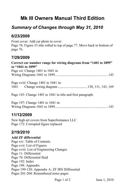
Special Events Preparation............................................116Driving School and High Speed Events .......................................116Routine Maintenance.............................................................................. 116Roll Bars................................................................................................. 116Seat Belts................................................................................................ 116Mirrors.................................................................................................... 117Tires........................................................................................................ 117Wheels.................................................................................................... 118Safety Wire............................................................................................. 118Anti-Sway Bar........................................................................................ 119Battery .................................................................................................... 119Battery Cut Off Switch........................................................................... 119Brakes..................................................................................................... 120Brake Lights ........................................................................................... 120Brake Fluid Ratings and Recommendations .......................................... 120Engine Oil .............................................................................................. 121Fuel Levels ............................................................................................. 121Locking Gas Cap.................................................................................... 121Fluid Levels............................................................................................ 122Fluid Leaks............................................................................................. 122Steering and Wheel Bearings ................................................................. 122Windscreen............................................................................................. 122Exhaust System ...................................................................................... 122Radiator Overflow Catch Can ................................................................ 122Throttle Return Spring............................................................................ 123Fire Extinguisher .................................................................................... 123Helmet .................................................................................................... 123Eye and Ear Protection........................................................................... 123Trunk and Cockpit.................................................................................. 123Numbers ................................................................................................. 124Tools and Spares .................................................................................... 124Top and Tonneau Cover ......................................................................... 124Body and Windscreen Protection ........................................................... 124Warm Up................................................................................................ 125Oil Pressure on the Track ....................................................................... 125Road Trips .......................................................................................126Routine Maintenance.............................................................................. 126Tools and Spares .................................................................................... 126Tool Kit ......................................................................................................... 126Tool and Spares Kit ....................................................................................... 127Car Cover ............................................................................................... 128Packing................................................................................................... 129Page xi
Electrical System ............................................................130Wiring Diagrams Up To 1040 .........................................................131Electrical Installation Information.......................................................... 131Distributor...................................................................................................... 131Gearbox ......................................................................................................... 131Alternator....................................................................................................... 131Relays, Flasher, Fuses ............................................................................ 132Wire Color Coding ................................................................................. 133Wiring Harness Diagrams ...................................................................... 134Drawing 1 of 8 - Front Loom......................................................................... 135Drawing 2 of 8 - Front Loom......................................................................... 136Drawing 3 of 8 - Dashboard Loom ................................................................ 137Drawing 4 of 8 - Dashboard Loom ................................................................ 138Drawing 5 of 8 - Dashboard Loom ................................................................ 139Drawing 6 of 8 - Rear Loop........................................................................... 140Drawing 7 of 8 - Alternator Wires................................................................. 141Drawing 8 of 8 - Electronic Ignition.............................................................. 142Wiring Diagrams 1041 to 1899.......................................................143Central Electrical Tray ........................................................................... 144Central Electrical Tray Components.............................................................. 144Fuse Box................................................................................................. 145No 5 Fuse Box – Version A........................................................................... 145No 5 Fuse Box – Version B ........................................................................... 146No 6 Fuse Box – Version A........................................................................... 147No 6 Fuse Box – Version B ........................................................................... 148Wiring Harness....................................................................................... 149Harness Layout Description ................................................................... 150Harness Information............................................................................... 1521. Front Loom Earth ..................................................................................... 1522a. L/H Headlight Plug (on Front Loom)...................................................... 1522b. Headlight Plug (on L/H Headlight)......................................................... 1523a. R/H Headlight Plug (on Loom)............................................................... 1533b. R/H Headlight Plug (on Headlight)......................................................... 1534a. L/H Front Indicator Plug (on Loom)....................................................... 1534b. L/H Front Indicator Plug (on Lamp)....................................................... 1535a. R/H Front Indicator Plug (on Loom)....................................................... 1545b. R/H Front Indicator Plug (on Lamp)....................................................... 1546. L/H Radiator Fan Terminals (On Radiator Fan) ....................................... 1547. R/H Radiator Fan Terminals (On Radiator Fan)....................................... 1548. Hooter Terminals (In Left Front Wheel Arch).......................................... 1549. Voltage Regulator Plug (On Front Loom) ................................................ 15510. Ballast Resistor Terminals (6mm Eye Rings) ......................................... 15511. Ignition Coil (Solder Joints).................................................................... 15512. L/H Side Indicator .................................................................................. 15513. R/H Side Indicator .................................................................................. 15614. Brake Fluid Level Terminals .................................................................. 15615. Distributor Plug on Loom ....................................................................... 156Page xii
CKT09 Ignition Module Circuit............................................................. 183CKT10 Wiper Motor, Reverse Light Circuit.......................................... 184CKT11 Fuel Level Circuit...................................................................... 185CKT12 Fuel Pump Circuit ..................................................................... 186CKT13 Seat Belt Buzzer Circuit (Australia).......................................... 187Ignition Circuit ....................................................................................... 18828 Pin Dash Connector........................................................................... 18928 Pin Front Harness Connector............................................................. 190Index ................................................................................191Appendices......................................................................198Appendix A: ZF IRS Differential ....................................................199Fluids...................................................................................................... 200Part Numbers.......................................................................................... 200Page xiv
[Figure 79 – Safety Wire, Right Side] ..................................................118[Figure 80 – Tool Kit Tucked Behind Driver’s Seat] ...........................127[Figure 81 – Tools and Spare Kit, Car Cover Stowed in Trunk] ..........128[Figure 82 – A Well Packed Trunk]......................................................129[Figure A1 – Rear of ZF IRS Differential] ...........................................199Page xvii
LIST OF ENGINEERING CHANGESThe following list includes only engineering changes referenced inthis manual. Car numbers are approximate as described inIdentifying Engineering Changes, page 16.Car Brief Description of EC Refer to Page150 Change from steel to Trigo wheels ..........................................11150 Change ball joints ....................................................................78300 Change seat structure ...............................................................16680 Change from Ford to Wilwood brakes.....................................13800 Change from Trigo to WAW1 wheels ...............................11, 89800 Add locking gas cap...............................................................121980 Change from AVO to Bilstein shocks................................14, 841041 Change wiring diagram.................................. 130, 131, 143, 1691200 Change to larger rear sway bar ........................................15, 1191200 Change from WAW1 to WAW2 wheels............................11, 891200 Change windscreen and cowl height................................15, 1091500 Change parking brake ..............................................................141500 Change soft top ........................................................................451664 Change to sealed beam headlight.............................................801900 Change dash layout ..................................................................211900 Change wiring diagram.................................. 130, 131, 143, 1692068 Change from Ford to BTR differential ..............................10, 762068 Add Ford modular DOHC 4V as supported engine...................92100 Change windscreen ..........................................................15, 1092680 Change from Wilwood to Wilwood/PBR brakes.....................132680 Change parking brake ..............................................................142750 Change from Wilwood/PBR to Wilwood brakes.....................132977 Change from BTR to ZF differential .....................................199Page xviii
from 3.08 to 5.13 are available from Ford Racing PerformanceParts. A number of owners have re-geared their differential.Beginning with approximately chassis number 2068, the <strong>Mk</strong> <strong>III</strong>began using the same BTR Automotive IRS differential used in thecurrent Australian built Pontiac GTO. The BTR uses Dana gearswith a 3.46 rear end ratio. The <strong>Mk</strong> <strong>III</strong> uses a cone type limited slipdifferential. The Superformance Coupe uses the same BTRdifferential, but with a sealed Hydratrac limited slip. Optionalratios are not available.For identification purposes, the BTR Automotive differential haseight ribs running front to back on the bottom with “BTRAutomotive” between the ribs toward the snout. The Forddifferential has only a few circumferential ribs.For the ZF differential, see Appendix A, page 199.WheelsEarly cars from car number 032 to approximately 150 had asstandard 15” stamped steel wheels with a Halibrand look-alikefiberglass wheel cover held in place by the knock-off spinner.Trigo 15” wheels were optional.Beginning with approximately car number 150, the 15” Trigowheels became standard. A number of dealers and owners installed17” wheels from PS Engineering.Beginning with approximately car number 800, Superformancebegan using 15” wheels from Wheelcraft Alloy Wheels (WAW) inSouth Africa and shortly thereafter offered the WAW optional 17”wheels. These early WAW wheels are referred to in this manual asWAW1.Beginning with approximately car number 1200, the design of theWAW sourced wheels changed. These later WAW wheels arereferred to in this manual as WAW2.Page 11
The Trigo, PS Engineering, WAW1, and WAW2 wheels are allcast aluminum Halibrand look-alike true knock-offs with 5-pindrive and three ear spinners. However, there are detaileddifferences that affect interchangeability. Interchanging thesewheels without accommodating these differences can result in adangerous situation.See the Wheels and Tires section in Maintenance, page 89, for fulla full description of the wheels and details on interchangeabilitybefore attempting to interchange wheels.Standard 15” WheelsFront Wheels..............................................................15" x 7.5” (8J)Rear Wheels.............................................................15" x 9.5” (10J)Optional 17” WheelsFront Wheels.....................................................................17” x 9.5”Rear Wheels....................................................................17” x 11.5”TiresRecommended 15” Tire SizesTireSizeFront.................................................................................. 255/60-15Rear................................................................................... 275/60-15Optional rear ..................................................................... 295/50-15Recommended 17” Tire SizesTireSizeFront.................................................................................. 275/40-17Rear................................................................................... 335/35-17Optional rear ..................................................................... 315/35-17NOTE: The speedometer is geared for the 275/60-15 rear tire. Useof another size rear tire may require a change in the speedometergears. The speedometer gear can be changed from below withoutremoving the transmission.Page 12
marks on the dip stick. Top up with the recommended oil ifrequired.The oil level should be checked at operating temperature,immediately after stopping the vehicle while parked on levelground. The dip stick must be securely replaced to avoid oilleakage.Check the oil every fuel fill up. High performance engines can useas much as a quart of oil every 500 miles by design.Filling Engine OilPark the car on level ground and turn off the engine. The engine oilfiller cap is typically located on top of the left hand side enginetappet cover. To remove, simply pull upward.Oil Usage Notes1) Running the car with an oil level above the maximum maycause oil wastage.2) Running the car with an oil level below the minimum couldcause considerable damage to the engine.3) The engine oil should be changed before and after every trackevent.4) For track event usage the oil should be topped up to themaximum mark. Monitor the oil level throughout the day andtop off as needed.5) Use a high quality, high flow oil filter and change with everyoil change.Transmission FluidThe transmission fluid specifications depend on the transmissioninstalled. Your transmission provider should provide the oil changespecifications.Fluid capacity: __________ quartsFluid type: ______________________Fluid change intervalBreak in: __________ milesRoutine: __________ milesPage 75
Typical intervals for Tremec transmissions are 15,000 miles forbreak in and every 30,000 miles thereafter for routine driving.The Tremec 3550 and TKO 5-speed transmissions require 2.75quarts of transmission fluid such as GM Synchromesh II orequivalent.Differential FluidRear axle fluid normally does not require replacement in absenceof repairs. See Differential, page 10, to identify differential type.Ford 8.8 Differential: For the early cast iron 8.8 differential, Fordrecommends 85w90 gear lube. For the later aluminum 8.8differential, 75w140 synthetic is the proper lube recommendedby Ford. For either, add 2.5 quarts of gear oil and one bottle(4 oz) of Ford Motorsports M19546-A friction modifier.BTR Automotive Differential: The required fluid is 1.64 quartsof GM # 89021809, special for this unit. It also requires 1ounce of GM additive # 89021958, again specific for this unit.ZF Differential: See page 200.Brake Fluid – Adding, Bleeding, and ReplacingThe brake fluid reservoir is mounted directly on the brake mastercylinder. Due to the location of the brake master cylinder under thedriver side fender, a funnel with flexible hose is required to addfluid (Figure 53). A large syringe and tubing can also be used. Becareful when removing the cap and gasket. They are easy to dropand hard to find.[Figure 53 – Filling Brake Master Cylinder]Page 76
To bleed the brakes or replace the brake fluid, use a Mityvac®,Motive® or equivalent vacuum pump and follow the instructionsprovided with the pump. Remove the wheels first. There is a bleedvalve on each brake caliper.NOTE: Any DOT 3 or DOT 4 or DOT 5.1 fluid can be used. DONOT use DOT 5. See Brake Fluid Ratings page 120.CAUTION: Brake fluid is corrosive to paint. Use care not to spillfluid on the finish. Any spills should be immediately flushed awaywith fresh water. Do not overfill as it may cause fluid to leak out.BRAKE FLUID WARNING BUZZER: A low brake fluid levelwill cause a warning buzzer, behind the dashboard, to sound whenswitching on the ignition.Clutch Fluid – Adding, Bleeding, and ReplacingThe clutch fluid is located in the remote reservoir on the firewall(Figure 54).[Figure 54 – Clutch Master Cylinder]To bleed the clutch or replace the clutch fluid, use a Mityvac®,Motive® or equivalent vacuum pump and follow the instructionsprovided with the pump. The bleed valve is on the clutch slavecylinder. Check the fluid level often and be careful not to suck allthe fluid out of the clutch master cylinder as clearing the air is adifficult task.Page 77
NOTE: Any DOT 3 or DOT 4 or DOT 5.1 fluid can be used. DONOT use DOT 5. See Brake Fluid Ratings page 120.NOTE: The clutch slave cylinder seals have a tendency to failafter several years. Consider replacing the slave cylinder every fiveyears as preventative maintenance. If the fluid is black when bled,change the slave cylinder now.CAUTION: Brake fluid is corrosive to paint. Use care not to spillfluid on the finish. Any spills should be immediately flushed awaywith fresh water. Do not overfill as it may cause fluid to leak out.Engine CoolantThe engine coolant is a 50/50 mixture of anti-freeze and water. Thecoolant should be filled at the header tank which is mounted on thefront of the engine above the water pump.Spark Plugs and Change IntervalThe type of spark plugs depends on the engine you have selected.Your engine provider should provide the spark plug specifications.Plug type: ___________________________________Plug change interval: Every __________ miles.A reasonable spark plug replacement interval is every 12,000 forconventional spark plugs and every 50,000 miles for platinum andiridium spark plugs. Platinum and iridium plugs can last longerthan 50,000 miles, but the risk of seizure in an aluminum headincreases if they are left in longer.NOTE: When installing spark plugs in aluminum heads, coat thethreads sparingly with anti-seize compound.Ball JointsOn cars from 32 to approximately 150, the ball joints were sealedand could not be lubricated. Later cars have screw in joints whichcan be lubricated. It is recommended that the cars with sealed ballPage 78
Primary DifferencesThe primary differences that affect interchangeability are shown below.Differences from the current WAW2 wheels are shown in bold.Dimensions given are approximate and may vary somewhat.Wheel Trigo WAW1 WAW21/2” rear spacer Yes (1) No NoRear lug stud length Plus 0.5” Std StdFront adapter length 4” 4” 4”Rear adapter length 4” 4.5” 4”Front wheel center thickness 2.7” 2.7” 2.7”Rear wheel center thickness 2.7” 3.2” 2.7”Rear wheel ID measurement 5.0” (2) 5.25” 4.75”Spinner cone angle 60° 60° 60°Wheel cone angle 60° 60° 60°Spinner contact width 1/4” 1/2” 1/2”Spinner step No Yes NoDrive pin diameter 0.745” 0.765” 0.765”Drive pin hole diameter 0.775” 0.775” 0.775”Note (1): Some dealers and owners have removed the rear spacer.Note (2): 4.5” when the rear spacer has been removed.C Adapter lengthD Wheel center thicknessB Wheel and spinner cone angleA Rear wheel ID measurement[Figure 64 – Wheel Dimensions]Page 93
Rear Spacer and Rear Lug Stud: The stamped steel and Trigorear wheels use a 1/2” aluminum spacer between the hub and theadapter to provide clearance for the rear brake caliper. The rearwheel lug studs are 1/2" longer to accommodate the spacer. WAWwheels do not have the spacer. The WAW1 wheels use a 1/2”longer rear adapter. The WAW2 wheels use a modified rear wheelhub design. Please see Additional Information, page iv.Front Adapter Length and Wheel Center Thickness: All Trigoand WAW wheels have a 4” long adapter and a 2.7” thick wheelcenter thickness except the WAW1 rear wheels which have a 4.5”long adapter and a corresponding 3.2” wheel center thickness.[Figure 65 – 4” Adapter and 4.5” Adapter]Spinner Cone Angle: The spinner cone angle is 60° for both theTrigo and WAW wheels. For some of the early WAW1 spinnersthe cone angle was slightly greater than 60°. This was an anomalyand was subsequently changed to 60°.Spinner Contact Width: The WAW spinners have a deeper coneface than the Trigo spinners and a corresponding larger contactarea with the wheel as shown in Figure 66. The width of thecontact area is 1/4” for the Trigo wheels and 1/2” for the WAWwheels. This difference does not affect the function of the spinner.Spinner Step: The WAW1 spinners have a step between the coneand the ears as shown in Figure 67. This step does NOT exist onthe Trigo or WAW2 spinners as shown in Figure 66. This step canbottom out on Trigo and WAW2 wheels. Therefore, WAW1Page 94
spinners should NOT be used with Trigo or WAW2 wheels.However, Trigo and WAW2 spinners can be used on WAW1wheels.[Figure 66 – Trigo (left) and WAW2 (right) Spinners][Figure 67 – WAW1 Spinner Showing Step]Driver Pin Diameter and Drive Pin Hole Diameter: The Trigo andWAW wheels have a 0.775” drive pin hole diameter. The Trigo wheelsuse a 0.745” diameter drive pin. The WAW wheels use a 0.765”diameter drive pin. Trigo wheels may be used with WAW drive pins andWAW drive pins may be used with Trigo wheels.See the Drive Pins section, page 100, for proper drive pinmaintenance.WAW2 drive pins vary up to 0.770”, a tight fit whichrequires particular care.Page 95
Drive Pin Wrench Variations: Drive pins have either a 1/2”6-point hex (Allen) drive, a 12 mm 6-point drive, or a 12 mm 12-point drive. The proper drive size and type must be used to avoiddamaging the drive pins. A damaged drive pin may make itimpossible to re-install the wheel since the fit is tight.[Figure 68 – 6 Point and 12 Point Drive Pins]Figure 68 shows from left to right a 6-point hex drive pin, a12-point drive pin, and a 6-point drive pin with threads extendingup into the socket area. The extended thread drive pin may help ifthe drive pin bottoms on the lug stud.A 1/2” drive will not fit in a 12 mm socket. A 12 mm drive will fitin a 1/2” socket, but it is loose. Try both a 1/2” and 12 mm drive tomake sure that you are using the correct size.InterchangeabilityThe Trigo and WAW spinners are interchangeable with thefollowing exception:(1) WAW1 spinners should NOT be used on Trigo or WAW2wheels.The Trigo and WAW wheels are interchangeable with thefollowing exceptions:(1) The WAW1 rear wheel can only be used with the WAW1 4.5”long adapter. If it is used on the 4” long adapter, 1/2” ofthreads are covered and the spinner will only contact a fewthreads, an unacceptable situation.(2) The 4.5” long adapter can only be used with the WAW1 rearwheel. If another wheel is used with the 4.5” long adapter, thePage 96
spinner can bottom out on the adapter before securing thewheel, an unacceptable situation. In addition, the wheel maynot fully seat on the adapter, also an unacceptable situation.(3) Fitting the Trigo rear wheels to a car without the 1/2” rearspacer may require modifications to the rear wheel and rear lugstuds. Fitting the WAW rear wheels to a car with the 1/2” rearspacer may require removal of the spacer and trimming of therear lug studs. Please see Additional Information, page iv.Purchasing Another Set of WheelsIf you purchase another set of wheels, check all the PrimaryDifferences noted above to make sure that your wheels arecompatible.If you have WAW1 wheels, it will be difficult to find aftermarketwheels that fit the WAW1 rear adapter. You probably will have toreplace the 4.5” WAW1 rear adapter with a 4” adapter and replacethe WAW1 spinners with WAW2 spinners. If you wish to continueusing the original wheels along with the new wheels, you will needto replace the WAW1 rear wheel with a WAW2 rear wheel, orchange the rear adapter every time you change wheels. You cancontinue to use the WAW1 front wheel and adapter.If you have more than one set of wheels and change themfrequently, it is recommended that you have the same rear wheeladapter for both. Changing the adapters frequently is tedious andincreases the chance of damaging a drive pin in which casemounting the wheel can be difficult or impossible.When changing to different wheels, check each of these items tomake sure the wheels are secure.(1) The drive pins can bottom out on the lug studs.(2) The wheel may not fully seat on the adapter. If the wheel isfully seated, it will “clunk” into place. If the wheel wobbles, itis not fully seated.(3) The spinner can bottom out on the adapter.(4) The spinner can bottom out on the wheel.(5) The wheel may not clear the brake calipers.Page 97
Wheel Removal and Reinstallation[Figure 69 – Right Side Front And Rear Wheel Spinners][Figure 70 – The Left Side Front And Rear Wheel Spinners]The right side spinners are loosened by turning them clockwise andtightened by turning them counterclockwise (Figure 69). The leftside spinners are loosened by turning them counterclockwise andtightened by turning them clockwise (Figure 70).When a wheel has to be removed, the spinner should be struckwith a 6 pound lead hammer in the direction of the wheel rotationPage 98
Drawing 5 of 8 - Dashboard LoomPage 139
Drawing 6 of 8 - Rear LoopPage 140
Wiring Diagrams 1041 to 1899Beginning with car number 1041, the electric system wasredesigned around a Central Electrical Tray.The Central Electrical Tray is located under the left hand side ofthe dash. The tray is hinge toward the front of the car and latchedtoward the rear. Two screws, one screw, or a loop and knob securethe tray. Remove the screw(s) or loop and the tray will swing downto expose the components.If your car has the Central Electrical Tray and the original versionof the dashboard, use the diagrams for car number 1041 to 1899.If your car has the Central Electrical Tray and the new version ofthe dashboard, use the diagrams for car number 1900 on.When removing any electrical component please note and recordthe wiring positions so that it can be correctly reinstalled.Because of continual running changes, the wiring in your car mayvary somewhat from the wiring diagrams presented here.Detailed color coded wiring diagrams are available separately foreach of the three electrical systems. See Additional Informationpage iv.NOTE: Prior to car number 1288, there was one relay for bothradiator fans as shown. Starting with car number 1288, there aretwo radiator fan relays, one for each fan.NOTE: Cars up to car number 1663 use a headlight bulb and arunning light in a headlight shell. Cars after 1663 use a sealedbeam headlight with the running light in the front indicator light.Page 143
Central Electrical TrayCentral Electrical Tray Components1.......Voltage stabilizer2.......Flasher unit3.......Headlight dimmer / dip relay4.......Main fuse5.......No 5 Fuse Box6.......No 6 Fuse Box7.......Brake fluid buzzer8.......Dash dimmer unit9.......Starter inhibit relay10.....Radiator fan relay (see notes, previous page)Page 144
Central Electrical TrayPage 171
Central Electrical Tray Harness RoutingPage 172
INDEX10th Anniversary <strong>Edition</strong>........................................................................16Acknowledgements...................................................................................vAdditional Information .............................................................................vAlignment and Adjustments....................................................................84Alternator Warning Light (9)..................................................................29Ammeter or Voltmeter (6) ......................................................................28Anti-Sway Bar ......................................................................................119Anti-Sway Bars.......................................................................................15Anti-Sway Bars.......................................................................................18Automatic Radiator Fans (15).................................................................31Ball Joints................................................................................................78Battery.....................................................................................................79Battery...................................................................................................119Battery Cables and Connections Check ..................................................80Battery Cut Off Switch .........................................................................119Blower Fan (24) ......................................................................................34Body..........................................................................................................2Body and Windscreen Protection..........................................................124Brake Fluid – Adding, Bleeding, and Replacing ....................................76Brake Fluid Ratings and Recommendations.........................................120Brake Fluid Warning Buzzer (12)...........................................................30Brake Lights..........................................................................................120Brakes .....................................................................................................13Brakes .....................................................................................................18Brakes ...................................................................................................120Brakes - Ford Brakes ..............................................................................13Brakes - Wilwood Brakes .......................................................................13Car Cover..............................................................................................128Car Number - <strong>Mk</strong> <strong>III</strong> Car Number ..........................................................20Carpets ..................................................................................................115Ceramic Coated Side Pipes...................................................................113Chassis ......................................................................................................2Chassis Identification..............................................................................19Chassis Number - <strong>Mk</strong> <strong>III</strong> Chassis Number .............................................19Cigar Lighter Receptacle (22).................................................................33Clutch Adjustment ..................................................................................87Clutch Fluid – Adding, Bleeding, and Replacing ...................................77Page 191
Congratulations!.......................................................................................iiiCooling......................................................................................................4Dashboard - <strong>Mk</strong> <strong>III</strong> Roadster Style Dashboard, New Version................25Dashboard - <strong>Mk</strong> <strong>III</strong> Roadster Style Dashboard, Original Version..........24Dashboard - <strong>Mk</strong> <strong>III</strong> SC Style Dashboard, New Version.........................23Dashboard - <strong>Mk</strong> <strong>III</strong> SC Style Dashboard, Original Version ...................22Dashboard Dimmer (17) .........................................................................32Dashboard Layout...................................................................................21Differential......................................................................................10, 199Differential..............................................................................................18Differential Fluid ............................................................................76, 200Dimensions ...............................................................................................6Doors.......................................................................................................39Doors - Closing and Opening the Doors.................................................70Doors - Closing Doors with Side Windows Installed .............................63Doors - Opening Doors with Side Windows Installed............................64Dot Fasteners ..........................................................................................46Drive Pins..............................................................................................100Driving School and High Speed Events................................................116Dry Wash / Between Wax Detailing.....................................................113Drying the Interior ................................................................................115Electrical System ..................................................................................130Engine .......................................................................................................9Engine .....................................................................................................17Engine Coolant........................................................................................78Engine Oil ...............................................................................................74Engine Oil .............................................................................................121Engineering Changes - Identifying Engineering Changes ......................16Entry/Exit - Side Exhausts ......................................................................40Every 12 months or 10,000 miles ...........................................................72Every 6 months or 5,000 miles ...............................................................72Exhaust System.........................................................................................3Exhaust System.....................................................................................122Exhaust System Check............................................................................81Exterior .................................................................................................112Eye and Ear Protection..........................................................................123Filling Engine Oil ...................................................................................75Fire Extinguisher...................................................................................123Fitting......................................................................................................63Fittings ......................................................................................................3Page 192
Wheels...................................................................................................114Wheels...................................................................................................118Wheels - Optional 17” Wheels................................................................12Wheels - Purchasing Another Set of Wheels ..........................................97Wheels - Standard 15” Wheels ...............................................................12Wheels - Tips for Removing a Stuck Spinner.......................................101Wheels and Tires.....................................................................................89Windscreen .............................................................................................18Windscreen ...........................................................................................114Windscreen ...........................................................................................122Windscreen and Cowl Height .................................................................15Windscreen and Cowl Height ...............................................................109Windscreen Washer (14).........................................................................31Windscreen Wiper (18)...........................................................................32Wiring Diagrams 1041 to 1899.............................................................143Wiring Diagrams 1900 On....................................................................169Wiring Diagrams Up To 1040 ..............................................................131Page 197
APPENDICESSignificant changes to the Superformance <strong>Mk</strong> <strong>III</strong> after thepublication date of this manual (June 2009) will be listed in theappendices which follow.Page 198
Appendix A: ZF IRS DifferentialFebruary 2010.In late 2009 around approximately car number 2977,Superformance changed the differential in the <strong>Mk</strong> <strong>III</strong> and beganusing the ZF IRS (independent rear suspension) limited slipdifferential with a 3.45:1 ratio.The ZF differential is produced by ZF Lemforder in Australia forthe GM Holden line of cars, replacing the differential from BTRAutomotive. The ZF IRS differential can be identified by the ZFlogo cast into the rear of the differential housing.[Figure A1 – Rear of ZF IRS Differential]The mounting points on the Ford 8.8 IRS, BTR IRS, and ZF IRSare not the same. Switching from one to the other requiresmodifications to the <strong>Mk</strong> <strong>III</strong> chassis mounting points.Page 199
The ZF IRS differential is also used in the 2010 Chevrolet Camaro.The V8 automatic uses a 3.27:1 ratio and the V8 6-speed manualuses a 3.45:1 ratio. Parts and fluids are available from Chevroletdealers. A third ratio, 2.92, is available from Holden in Australia.FluidsThe part numbers are:Description Part #Synthetic Axle Lubricant 75W-90 89021677Limited Slip Axle Lubricant Additive 1052358The quantities required are:Description Metric US EnglishSynthetic Axle Lubricant 75W-90 0.925 liters 0.975 quartsLimited Slip Axle Lubricant Additive 0.075 liters 0.079 quartsPart NumbersThe GM part numbers for the Camaro complete differential and thering and pinion gear set are:Description Ratio Part #Complete differential 3.45:1 92239176Complete differential 3.27:1 92239177Ring and pinion set 3.45:1 92243259Ring and pinion set 3.27:1 92243260The GM part number for the Holden 2.92 ratio is:Description Ratio Part #Complete differential 2.92:1 92157714Page 200
NOTESPage 201
NOTESPage 202
NOTESPage 203
NOTESPage 204