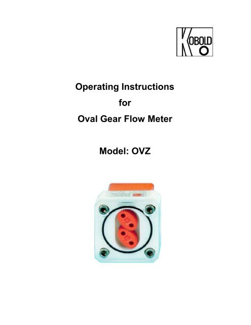
Operating Instructions for Oval Gear Flow Meter Model: OVZ - Kobold
Operating Instructions for Oval Gear Flow Meter Model: OVZ - Kobold
Operating Instructions for Oval Gear Flow Meter Model: OVZ - Kobold
Create successful ePaper yourself
Turn your PDF publications into a flip-book with our unique Google optimized e-Paper software.
<strong>Operating</strong> <strong>Instructions</strong><strong>for</strong><strong>Oval</strong> <strong>Gear</strong> <strong>Flow</strong> <strong>Meter</strong><strong>Model</strong>: <strong>OVZ</strong>
<strong>OVZ</strong>1. Contents1. Contents .................................................................................................... 22. Note ........................................................................................................................33. Regulation Use .......................................................................................... 34. <strong>Operating</strong> Principle............................................................................... 45. Instrument Inspection................................................................................. 46. Mechanical Connection.............................................................................. 57. Electrical Connection ..................................................................................67.1. General .............................................................................................. 67.2. Electronics: ........................................................................................ 77.3. Analog Output.................................................................................... 77.4. Compact electronics: ......................................................................... 77.5. Pointer Indication with Analog output (....Z340) ................................. 88. Electronics Operation.................................................................................. 88.1. Frequency output............................................................................... 88.2. Analog output ......................................................................... 88.3. Compact electronics ..........................................................................88.4. Pointer display (…..Z340) ................................................................. 89. Mechanical Operation .............................................................................. 1010. Technical In<strong>for</strong>mation............................................................................... 1011. Pressure loss ............................................................................................ 1111.1. POM- plastic housing ........................................................... 1111.2. Aluminum housing .......................................................................... 1212. Order Codes .............................................................................................1412.1. POM plastic housing....................................................................... 1412.2. Aluminum housing .......................................................................... 1413. Maintenance ............................................................................................ 1514. Dismantling / Installation ........................................................................... 1515. Recommended spare parts...................................................................... 1516. Dimensions .............................................................................................. 1617. Declaration of Con<strong>for</strong>mance .....................................................................19Manufactured and sold by:KOBOLD Instruments Inc.1801 Parkway View DrivePittsburgh, PA 15205Tel.: 412-788-2830Fax: 418-788-4890E-Mail: info@koboldusa.comWebsite: www.koboldusa.compage 2 <strong>OVZ</strong> 4-2013
<strong>OVZ</strong>2. NotePlease read these operating instructions be<strong>for</strong>e unpacking and putting the unitinto operation. Follow the instructions precisely as described herein.The devices are only to be used, maintained, and serviced by someonefamiliar with these operating instructions and in accordance with local regulationsapplying to Health & Safety and accident prevention.When installed into machines, the measuring unit should only be used when themachines fulfill the EWG-machine guidelines.PED 97/23/EGIn accordance with Article 3 Paragraph (3), "Sound Engineering Practice",of the PED 97/23/EC no CE mark. Diagram 8, Pipe, Group 1 dangerous fluids3. Regulation UseThe model <strong>OVZ</strong> is an oval gear, positive displacement flow meter which can beused to measure and monitor the flow rate of viscous liquid (min. 10 mm²/sto max. 800 mm²/s); (max. viscosity 1000 mm²/s upon request). Onlymeasure clean, non-abrasive liquids with adequate lubricating properties, andagainst which the materials used in the sensor case are chemically resistant.Ferrite particles may become deposited on the oval gears as they do containpermanent magnets, thus causing malfunctions, or destruction to the oval gears.We recommend our model MFR series magnetic filters, if the liquid contains ahigh concentration of ferrous solids. In case of uncertainty, please consult yoursupplier.Material combinations<strong>Model</strong> <strong>OVZ</strong>-..1.. <strong>OVZ</strong>-..2.. <strong>OVZ</strong>-..3.. <strong>OVZ</strong>-..4.. <strong>OVZ</strong>-..5..Case POM POM Aluminum Aluminum AluminumCase cover POM PMMA PMMA PSU AluminumAxle 304 Stainless steelRotating sensingtargetsCeramics (Hall sensor versions) stainless steel (inductivepickup versions)<strong>Oval</strong> gearsPOMO-ringStandard: NBR; option: FKM or EPDMmax. operating 145 PSI 145 PSI 232 PSI 232 PSI 580 PSIpressuremax. medium176 °Ftemperaturemax. ambient140 °FtemperatureFiltration requirements max. 30 µm<strong>OVZ</strong> 4-2013 page 3
<strong>OVZ</strong>4. <strong>Operating</strong> PrincipleThe <strong>OVZ</strong> oval gear meter is a positivedisplacementflow meter. The measuringelement comprises of two toothed precisionoval gears, which are driven by the liquid inletpressure. As the liquid rotates the gears, afixed quantity of liquid is transported throughthe chambers <strong>for</strong> every turn of the oval gearpair. Permanent magnets or stainless steelpins are embedded in the oval gears. Therotary gear motion is converted to a pulsesignal by electrical sensors externally fittedinto the casing. The pulse count is a measureof the flow rate. The signals are evaluated bydownstream electronics (optional).5. Instrument InspectionInstruments are inspected be<strong>for</strong>e shipping and sent out in perfect condition.Should the damage to a device be visible, we recommend a thorough inspectionof the delivery packaging. In case of damage, please in<strong>for</strong>m your parcelservice/<strong>for</strong>warding agent immediately, since they are responsible <strong>for</strong> damagesduring transit.Scope of delivery:• <strong>Oval</strong> gear meter model: <strong>OVZ</strong>• <strong>Operating</strong> <strong>Instructions</strong>page 4 <strong>OVZ</strong> 4-2013
<strong>OVZ</strong>7.5. Pointer display (....Z340)+VsPowerGNDn.c. 2 1 +VsGND Signal3 4 OutPlug M12mA• Plug the portable socket-outlet into its mating connector on the meter.8. Operation – Electronics8.1. Frequency outputThe instruments are pre-adjusted. After electrical connection they are ready <strong>for</strong>operation.8.2. Analog outputThe instruments are pre-adjusted. After electrical connection they are ready <strong>for</strong>operation.8.3. Compact electronicsThe instruments are pre-adjusted. After electrical connection they are ready <strong>for</strong>operation.For changing of setting, refer to operating manual <strong>for</strong> compact electronic withfrequency output.8.4. Pointer display (....Z340)The instruments are pre-adjusted. After electrical connection they are ready <strong>for</strong>operation.page 8 <strong>OVZ</strong> 4-2013
<strong>OVZ</strong>9. Mechanical Operation• To avoid pressure peaks, the fluid should flow slowly into the meter.Important! Pressure peaks arising from a sudden influx of liquid,caused by solenoid valves, ball valves etc, may seriously damage themeter (water hammer!). Ensure that the sensor is always filled withmedia when in the operating state.Important! Vent the piping, to prevent large air bubbles in the sensorchamber which may cause measuring errors, erratic flow reading,and can possibly seriously damage the bearings.10. Technical In<strong>for</strong>mationViscosity range: 10 to 800 mm 2 /s(option: 1000 mm 2 /s)Ambient temperature: 14 °F to 140 °FMedium temperature: 14 °F to 176 °FMax. pressure:<strong>OVZ</strong>-..1, <strong>OVZ</strong>-..2: 145 PSI<strong>OVZ</strong>-..3, <strong>OVZ</strong>-..4: 232 PSI<strong>OVZ</strong>-..5 : 580 PSIAccuracy: ± 2.5 % f. s.Filter mesh size: max. 30 µmMaterial:O-rings:Sensor targets:Frequency range:combination/case/cover<strong>OVZ</strong>-..1.. / POM /POM<strong>OVZ</strong>-..2.. / POM /PMMA<strong>OVZ</strong>-..3.. / aluminum /PMMA<strong>OVZ</strong>-..4.. / aluminum /PSU<strong>OVZ</strong>-..5.. / aluminum /aluminumoval gears: POMaxles: stainless steel 304NBR; option: FKM, EPDMoxide ceramic magnetsor stainless steel0.3-9 Hz to 2-57 Hz<strong>OVZ</strong> 4-2013 page 9
<strong>OVZ</strong>ElectronicsFrequency output (...l401; ...l302; ...l303)Power supply:5-24 V DCPower consumption:typically 10 mAPulse output:Hall effect sensor NPNopen collector, max. 15 mAElectrical connection: connector socket DIN 43650 (...I401)aluminum adapter box with cableconnection (...I302)aluminum cover box with circularconnector M12x1 (...I303)Frequency output (...l304)Power supply:Power consumption:Pulse output:Electrical connection:Frequency output (...l305)Power supply:Pulse output:Electrical connection:18-30 V DCtypically 10 mAPNP, asymmetrical, open collectormax. 120 mA2 m PVC cablenominal 8.2 V DCNamur, asymmetrical,max. approx. 3.5 mA (typ. 0.5 mA)2 m PVC cableFrequency output (...F300)Power supply: 24 V DC ± 20 %Power consumption:10 mAPulse output:PNP, open collector, max. 25 mAElectrical connection: connector M12x1Frequency output with frequency divider (...F3X0)Power supply: 24 V DC ± 20 %Power consumption:15 mAPulse output:PNP, open collector, max. 25 mAElectrical connection: connector M12x1Divisional factor:acc. to customer specificationAnalog output (....L343, ...L443)Power supply: 24 V DC ± 20 %Output:4-20 mA, 3-wireMax. load:500 ohmElectrical connection: connector M12x1 or DIN 43 650Option:plug-on display AUF-3000(with DIN connector only)page 10 <strong>OVZ</strong> 4-2013
<strong>OVZ</strong>Compact electronicsDisplay:Analog output:Switching outputs:Contact operation:Setting:Power supply:Electrical connection:3-digit LED4...20 mA adjustable, max. 500 Ω1 (2) semiconductor PNP orNPN, factory settingN/C, N/O programmablevia 2 keys24 V DC ± 20 %, 3-wireconnector M12x1Pointer display with analog outputHousing:aluminumIndication:moving coil instrum. 240 ° indicationPower supply: 24 V DC ± 20 %Output:4-20 mA, 3-wireMax. load:250 ohmElectrical connection: connector M12x111. Pressure loss11.1. POM- plastic housing<strong>OVZ</strong>-02...<strong>OVZ</strong>-04...<strong>OVZ</strong> 4-2013 page 11
<strong>OVZ</strong><strong>OVZ</strong>-15...<strong>OVZ</strong>-30...11.2. Aluminum housing<strong>OVZ</strong>-02...<strong>OVZ</strong>-04...page 12 <strong>OVZ</strong> 4-2013
<strong>OVZ</strong><strong>OVZ</strong>-15...<strong>OVZ</strong>-30...<strong>OVZ</strong> 4-2013 page 13
<strong>OVZ</strong>12. Order Codes12.1. POM plastic housing(Example: <strong>OVZ</strong>-02 1 N2 N I401)Rated measuring range (GPM) 1)(<strong>for</strong> different viscosities)10 mm²/s 100 mm²/s 320 mm²/s 800 m²/sPulsesPerGallon<strong>Model</strong>0.8 – 2.1 0.8 – 2.1 0.5 – 1.3 0.3 – 0.53 1546 <strong>OVZ</strong>-02..0.11 – 2.6 0.11 – 2.6 0.8 – 2.1 0.4 – 1.1 848 <strong>OVZ</strong>-04..0.26 – 6.6 0.26 – 6.6 0.26 – 6.6 0.11 – 2.6 199 <strong>OVZ</strong>-15..0.42 – 10.6 0.42 – 10.6 0.42 – 10.6 0.25 – 6.34 106 <strong>OVZ</strong>-30..1) Maximum pressure loss at maximum rated flow is 14.5 PSI2) Hz=Pulse/Gallon x Gallon/Minute/60Material/cover..1..= POM..2..= PMMAConnection Gaskets Electrical transducer..G2..= G 1/4..N2..= 1/4 NPT ..N..= NBR..G2..= G 1/4 (standard)..N2..= 1/4 NPT..G4..= G 1/2 ..V..= FKM..N4..= 1/2 NPT..G5..= G 3/4 ..E..= EPDM..N5..= 3/4 NPTFrequency output..I401= frequency output NPN, DIN connector 43650..I302= frequency output NPN, cable connection..l304= frequency output PNP, 2 m PVC cable..l305= frequency output Namur, 2 m PVC cable..F300= frequency output PNP, connector M12x1..F3X0= frequency divider adjusted PNP, connector M12x1Analog output..L343= 4-20 mA output, 3-wire, M12x1connector..L443= 4-20 mA output, 3-wire, DIN connectorCompact electronic*..C30R= LED-display, 2xopen collector, PNP, connector M12x1..C30M= LED-display, 2xopen collector, NPN, connector M12x1..C34P= LED-display, 4-20 mA, 1x op.coll.,PNP,connector M12x1..C34N= LED-display, 4-20 mA, 1xop.coll.,NPN, connector M12x1Pointer indication, 240°*..Z340= 240°-pointer indication,4.20 mA, connector M12x1* Please specify flow direction in writing12.2. Aluminum housing(Example: <strong>OVZ</strong>-02 3 N2 N I401)Rated measuring range (GPM) 1)(<strong>for</strong> different viscosities)10 mm²/s 100 mm²/s 320 mm²/s 800 mm²/sPulsesPerGallon<strong>Model</strong>Material/coverConnection Gaskets Electrical transducer0.8 – 2.1 0.8 – 2.1 0.07- 1.74 0.03 – 0.79 1499 <strong>OVZ</strong>-02.. ..G2..= G 1/4..3..= PMMA ..N2..= 1/4 NPT0.11 – 2.6 0.11 – 2.6 0.11 – 2.64 0.07 – 1.19 768 <strong>OVZ</strong>-04.. ..G2..= G 1/4..4..= PSU ..N2..= 1/4 NPT0.26 – 6.6 0.26 – 6.6 0.24 – 6.08 0.13 – 3.30 176 <strong>OVZ</strong>-15.. ..G4..= G 1/2..5..= Alu ..N4..= 1/2 NPT0.42 – 10.6 0.42 – 10.6 0.34 – 8.85 0.21 – 5.28 98 <strong>OVZ</strong>-30....G5..= G 3/4..N5..= 3/4 NPT1) Maximum pressure loss at maximum rated flow is 1 bar2) Hz = Pulse/Gallon x Gallon/Min/60..N..= NBR(Standard)..V..= FKM..E..= EPDMFrequency output..I401= frequency output NPN, DIN connector 43650..I302= frequency output NPN, cable connection..l304= frequency output PNP, 2 m PVC cable..l305= frequency output Namur, 2 m PVC cable..F300= frequency output PNP, connector M12x1..F3X0= frequency divider adjusted PNP, connector M12x1Analog output..L343= 4-20 mA output, 3-wire, M12x1connector..L443= 4-20 mA output, 3-wire, DIN connectorCompact electronic*..C30R= LED-display, 2xopen collector, PNP, connector M12x1..C30M= LED-display, 2xopen collector, NPN, connector M12x1..C34P= LED-display, 4-20 mA, 1x op.coll.,PNP,connector M12x1..C34N= LED-display, 4-20 mA, 1xop.coll.,NPN, connector M12x1Pointer indication, 240°*..Z340= 240°-pointer indication,4-20 mA, connector M12x1* Please specify flow direction in writingPlug-on display<strong>for</strong> <strong>Model</strong> <strong>OVZ</strong>... L4 ... (with 4-20 mA output and DIN-connector)Description3-digit LED, plug-connection DIN 43 6503-wire, power supply with analog outputOrder numberAUF-3000page 14 <strong>OVZ</strong> 4-2013
<strong>OVZ</strong>13. MaintenanceThe meter requires no maintenance if the measured media is not contaminated.Should it be necessary to clean the meter, the meter body cover can be easilyremoved to gain access to, and clean, the inside of the meter body (see Sec.12. Dismantling/Installation).14. Dismantling / InstallationDismantling:• Drain piping.• Loosen cover screws and remove cover and O-ring.• Mark the position of the gears relative to one another with a pencil.• Remove the pair of oval gears and clean parts with care; do not scratch thesealing faces.Caution: Do not remove the oval gears position marking!Installation:• Install the pair of oval gears; note identifying markings.• Rotate gears a number of times: they should not disengage.• Insert O-ring; replace meter body cover and firmly tighten screws crosswise.15. Recommended spare parts1.0 Pair of oval gears2.0 NBR, FKM, or EPDM O-ring3.0 POM, PMMA, PSU, or AL coverAlways specify the meter model when ordering spare parts.<strong>OVZ</strong> 4-2013 page 15
<strong>OVZ</strong>16. Dimensions<strong>OVZ</strong>-...l401G HF [mm][mm] [mm] ..1.. ..2.. ..3/ 4.. ..5..<strong>OVZ</strong>-02... 68 68 45 45 43,5 41<strong>OVZ</strong>-04... 68 68 49 49 47 44,5<strong>OVZ</strong>-15... 99 99 71 73 71 66<strong>OVZ</strong>-30... 119 119 84,5 87,5 86 79,5<strong>OVZ</strong>-...l302, <strong>OVZ</strong>-...l303G HF [mm][mm] [mm] ..1.. ..2.. ..3/ 4.. ..5..<strong>OVZ</strong>-02... 68 68 45 45 43,5 41<strong>OVZ</strong>-04... 68 68 49 49 47 44,5<strong>OVZ</strong>-15... 99 99 71 73 71 66<strong>OVZ</strong>-30... 119 119 84,5 87,5 86 79,5page 16 <strong>OVZ</strong> 4-2013
<strong>OVZ</strong><strong>OVZ</strong>-...l304, <strong>OVZ</strong>-...l305PNP NAMUR PNP/ NAMURA [mm] B [mm] A [mm] B [mm] G [mm] H [mm]<strong>OVZ</strong>-02.. 21,5 13,5 16,5 13,5 68 68<strong>OVZ</strong>-04.. 21 14 16 14 68 68<strong>OVZ</strong>-15.. 19 16 14 16 99 99<strong>OVZ</strong>-30.. 17 18 12 18 119 119<strong>OVZ</strong> 4-2013 page 17
<strong>OVZ</strong><strong>OVZ</strong>-...L3... <strong>OVZ</strong>-...F3... <strong>OVZ</strong>-...L443 with AUF-3000<strong>OVZ</strong> with frequency or analog output: overviewPlastic housing (POM)Description DimensionADimensionBDimensionC<strong>OVZ</strong>-02 1 = POM 13 45 68<strong>OVZ</strong>-02 2 = PMMA 13 45 68<strong>OVZ</strong>-04 1 = POM 13.7 49 68<strong>OVZ</strong>-04 2 = PMMA 13.7 49 68<strong>OVZ</strong>-15 1 = POM 15.65 71 99<strong>OVZ</strong>-15 2 = PMMA 15.65 73 99<strong>OVZ</strong>-30 1 = POM 17.6 84.5 119<strong>OVZ</strong>-30 2 = PMMA 17.6 87.5 119Aluminum housing (ALU)Description DimensionADimensionBDimensionC<strong>OVZ</strong>-02 3 = PMMA 11.5 43.6 68<strong>OVZ</strong>-02 4 = PSU 11.5 43.6 68<strong>OVZ</strong>-02 5 = ALU 11.5 41.1 68<strong>OVZ</strong>-04 3= PMMA 11.5 47 68<strong>OVZ</strong>-04 4 = PSU 11.5 47 68<strong>OVZ</strong>-04 5 = ALU 11.5 44.5 68<strong>OVZ</strong>-15 3= PMMA 13.35 71 99<strong>OVZ</strong>-15 4 = PSU 13.35 71 99<strong>OVZ</strong>-15 5 = ALU 13.35 66 99<strong>OVZ</strong>-30 3= PMMA 15.75 86 119<strong>OVZ</strong>-30 4= POM 15.75 86 119<strong>OVZ</strong>-30 5= PMMA 15.75 79.5 119page 18 <strong>OVZ</strong> 4-2013
<strong>OVZ</strong><strong>OVZ</strong>-…C3…<strong>OVZ</strong>-…Z3…<strong>OVZ</strong> with compact electronics: overviewPlastic housing (POM)Description DimensionADimensionBDimensionC<strong>OVZ</strong>-02 1 = POM 19.525 45 68<strong>OVZ</strong>-02 2 = PMMA 19.525 45 68<strong>OVZ</strong>-04 1 = POM 16.95 49 68<strong>OVZ</strong>-04 2 = PMMA 16.95 49 68<strong>OVZ</strong>-15 1 = POM 21.125 71 99<strong>OVZ</strong>-15 2 = PMMA 21.125 73 99<strong>OVZ</strong>-30 1 = POM 23.2 84.5 119<strong>OVZ</strong>-30 2 = PMMA 23.2 87.5 119Aluminum housing (ALU)Description DimensionADimensionBDimensionC<strong>OVZ</strong>-02 3 = PMMA 19.525 43.6 68<strong>OVZ</strong>-02 4 = PSU 19.525 43.6 68<strong>OVZ</strong>-02 5 = ALU 19.525 41.4 68<strong>OVZ</strong>-04 3= PMMA 19.525 47 68<strong>OVZ</strong>-04 4 = PSU 19.525 47 68<strong>OVZ</strong>-04 5 = ALU 19.525 44.5 68<strong>OVZ</strong>-15 3= PMMA 21 71 99<strong>OVZ</strong>-15 4 = PSU 21 71 99<strong>OVZ</strong>-15 5 = ALU 21 66 99<strong>OVZ</strong>-30 3= PMMA 23.025 86 119<strong>OVZ</strong>-30 4= POM 23.025 86 119<strong>OVZ</strong>-30 5= POM 23.025 79.5 119<strong>OVZ</strong> 4-2013 page 19
<strong>OVZ</strong>17. Declaration of Con<strong>for</strong>manceWe, KOBOLD Messring GmbH, Hofheim-Ts, Germany, declare under oursole responsibility that the product:<strong>Oval</strong> <strong>Gear</strong> <strong>Flow</strong> <strong>Meter</strong><strong>Model</strong>: <strong>OVZ</strong>-...to which this declaration relates is in con<strong>for</strong>mity with the standards noted below:EN 50082-2EMC General Immunity Requirementsa) Immunity against electrostatic discharges(IEC 0801-2, ESD).b) Immunity against fast transients.(IEC 1000-4, BURST)Also the following EWG guidelines are fulfilled:2004/108/ECEMC DirectiveHofheim, 16. Jan. 2007H. Peters M. WenzelGeneral Manager Proxy Holderpage 20 <strong>OVZ</strong> 4-2013
<strong>Operating</strong> InstructionSupplement<strong>for</strong>Compact Electronics<strong>Model</strong>:..C30R;..C30M..C34P;..C34N
...C3...1. Contents1. Contents........................................................................................................22. Note ..............................................................................................................33. Electrical Connection ....................................................................................34. Programming ................................................................................................55. Maintenance ...............................................................................................126. Technical In<strong>for</strong>mation..................................................................................12Manufactured and sold by:<strong>Kobold</strong> Messring GmbHNordring 22-24D-65719 HofheimTel.: +49(0)6192-2990Fax: +49(0)6192-23398E-Mail: info.de@kobold.comInternet: www.kobold.comSeite 2 ...C3... 07/04
...C3...2. NoteThis programming instruction is only a supplement to the operatinginstruction <strong>for</strong> the sensor.3. Electrical Connection3.1. GeneralAttention! Make sure that the voltages in your plant correspondwith the instrument voltages• Make sure that the supply wires are de-energized.• Connect the supply voltage and evaluation of both output signals to the plugconnector PINs as shown in section 3.2 and 3.3.• We recommend the use of wires with cross sectional area of min. 0,25 mm²Attention! Incorrect wiring will lead to damage of the unit’selectronics....C3... 07/04 Seite 3
...C3...3.2. Compact Electronics: (..C30R, ..C30M)Switch out 2+ VsGNDGND23 514Switch out 13.3. Compact Electronics: (..C34P, ..C34N)(0)4-20 mA+ VsGNDGND23 514Switch out 1Terminals 3 and 5 are linked internally and can there<strong>for</strong>e be used either <strong>for</strong> theoutput signal or the power supply.Seite 4 ...C3... 07/04
...C3...4. ProgrammingConnect the compact electronics according to the previous wiring diagram andapply the specified voltage.The measuring range (upper range value) is displayed <strong>for</strong> 3 seconds afterswitch-on.4.1. Key FunctionStandard mode (measuring mode): pressing 3 sec. set-up mode: switchpoint/window pointSet-up mode: Next level: Set value3 secAnytime:or 20 secno key pressing4.2. SettingsStandard modeThe following values can be changed in the compact electronics:Scale rangeFactory settingSwitching point (SPo, SP1, SP2) 0 - 999 0.00Hysteresis (HYS) -199 - 0 -0.00Window point (duo) Switching point ...999 --- (de-activated)Filter (Filt) 1/2/4/8/16/32/64 1Contact type (Con, Co1, Co2) N/O contact (no), N/C (nc) no (N/O contact)or frequency (Fr)**Start current (S-C)* 000 - 999 000End current (E-C)* 000 - 999 Upper range valueStart current selection (SCS) 0-- (0 mA), 4-- (4 mA) 4 mAChange code (CCo) 000 - 999 000* Lower and upper range values of the flow rate are based on 0/4-20 mA.** only <strong>for</strong> sensors with impulse output (e.g. DPE)...C3... 07/04 Seite 5
...C3...4.3. Value SettingYou can select Value setting in the main menu item (<strong>for</strong> example: Switchingpoint, "SPo") by pressing the "" key. The structure shown below illustrates theuniversal routine <strong>for</strong> changing individual parameters.from the main menu item1. Digit setting2. Digit setting3. Digit settingStoringDecimal pointsettingChoosed valuestoring or newsettingto the next main menu itemSeite 6 ...C3... 07/04
...C3...4.4. Set-up Mode3 secCode enteringCode=Value settingSwichtingpoint 1Value settingSwitchingpoint 2Value settingHysteresisValue settingFilter7 LevelsValue settingContact 1functionN/ON/CFrequency*StoringContact 2functionN/OStoringChanging codeValue setting*Only <strong>for</strong> sensors with impulse output...C3... 07/04 Seite 7
...C3...3 secCode enteringCode=Value settingSwitching pointValue settingHysteresisValue settingWindowpointValue settingFilter7 levelsValue settingContact functionN/ON/CFrequency*StoringStart current7secValue settingEnd current7secValue setting*Only <strong>for</strong> sensors with impulse outputSeite 8 ...C3... 07/04
...C3...Analog outputchoosing7sec0-20mAChanging code4-20mAStoringValue setting4.5. Main Menu ItemsSwitching pointThe switching point is entered in menu item "SPo, SP1, SP2". A value in therange 000 to 999 may be chosen. A decimal point position is also assigned tothis value. The position of the decimal point can be set after the first, second orlast position (no decimal point). If the indicated value exceeds the set switchingpoint, then the electronics switches and energizes the LED.If the hysteresis is equal to zero and the window point is de-activated, theelectronic switches back whenever the indicated value falls below the switchingpoint.HysteresisAfter the switching point, hysteresis can be entered as a negative value in themenu "HYS". The default hysteresis value is zero. However this can lead toconfused switching, when the measuring signal fluctuates around the switchingpoint or window point. This problem can be cured by increasing the hysteresis.The hysteresis is based on the switching point and the window point (switchingpoint minus hysteresis; window point plus hysteresis).Example: switching point 100 l/min; hysteresis: -2.5 l/minThe electronics switches when 100 l/min is exceeded and switchesback when the flow rate falls below 97.5 l/min.Window point (duo point)A window point "duo" (duo point) can be defined in addition to the switchingpoint. The window point must be greater than the switching point. The measuredvalue can be monitored within a set range by means of the window point andswitching point. The switching point marks the lower end of the range of valuesand the window point the upper end....C3... 07/04 Seite 9
...C3...If the window point (duo point) is lower than or equal to the switching point,an error message is displayed (Er4), its value is then deleted and thus itsfunction is disabled (applies to window point and switching point setting).Value setting is similar to switching point setting.The window point serves to monitor the measured value within a set range.Example: Switching point: 100 l/min; window point: 150 l/min; hysteresis: -1 l/minThe electronics switches when 100 l/min is exceeded. When the measured valuestays within the limits 99 l/min (100-1) and 151 l/min (150+1), then the electronicsalso remains in the activated switch state (LED on). Should the measured valueexceed 151 l/min or drop below 99 l/min, then the electronics switches back.Switching per<strong>for</strong>manceThe switching per<strong>for</strong>mance of the electronics is illustrated in the diagram below.The contact closes (N/O contact) when the switching point is exceeded or whenthe value drops below the window point. It opens when the window point plushysteresis is exceeded or when the value drops below the switching point minushysteresis. The switch state of the electronics is indicated by an LED.Displaybar (°C)LED onSwitchingpointHysteresisTime / tDisplaybar (°C)HysteresisWindow pointLED onLED onSwitching pointHysteresisTime / tSeite 10 ...C3... 07/04
...C3...FilterThe filter function "Filt" generates the sliding average value from the measuredvalues. The following values are available (see section 6.2 Settings):1 / 2 / 4 / 8 / 16 / 32 / 64The filter value determines the dynamic behaviour of the indicated value: highvalues result in a slow display response. The filter is disabled if a filter value of"1" is selected. In other words, the indicated value is equal to the unfilteredmeasured value.The integrated step detector responds to a measured-value step change greaterthan approximately 6.25% of the upper range value. When a measured-valuestep change is detected, the actual measured value is displayed immediately.Contact <strong>Model</strong>The function of the transistor switching output is set in menu item "Con, Co1 orCo2". The switching function switches fromno - N/O contact tonc - N/C toFr – frequency(Con and Co1 only and<strong>for</strong> sensors with impulseoutput)and back.N/O contact means: contact closes when switching point is exceededN/C means: contact opens when switching point is exceededFrequency means: frequency output synchronized with vane frequencyCurrent outputThe current output is selected in menu items"S-C" Start current indicated value < > 0(4) mA"E-C" End current indicated value < > 20 mA"SCS" Start current selection (0-20 mA or 4-20 mA).The indicated value at which 0(4) mA flow is entered in menu item Start current.The indicated value at which 20 mA flow is entered in menu item End current.Change CodeThe change code option "CCo" secures the unit against unauthorised tempering.If the code is different from 000, the user must input the code immediately afterentering the adjustment mode....C3... 07/04 Seite 11
...C3...5. MaintenanceWork on the electronics should only be carried out by the supplier, otherwise theguarantee is nullified.6. Technical In<strong>for</strong>mationDisplay:Display case:Analogue output:Transistor output:Frequency output:Max. switching current:Function:Setting:Supply:Electrical connection:3-segment LEDstainless steel(0)4 - 20 mA scalable (...C34 only)1 (2) semiconductor PNP or NPN,set at the factory.1 transistor outputvane frequency (see sensor)300 mAN/C / N/O contact programmablewith 2 buttons24 VDC ±20%, 3-wire technologyplug connector M12x1Seite 12 ...C3... 07/04


