introduction to the catalogue - Ilme SpA
introduction to the catalogue - Ilme SpA
introduction to the catalogue - Ilme SpA

Create successful ePaper yourself
Turn your PDF publications into a flip-book with our unique Google optimized e-Paper software.
general index<strong>introduction</strong> <strong>to</strong> <strong>the</strong> <strong>catalogue</strong>page● general overview of <strong>the</strong> production of multipole connec<strong>to</strong>rs for industrial purposes 3 ÷ 7● general features of multipole connec<strong>to</strong>rs 8 ÷ 9● standards governing <strong>the</strong> use of multipole connec<strong>to</strong>rs 10 ÷ 12● features of inserts for multipole connec<strong>to</strong>rs 13 ÷ 17● conduc<strong>to</strong>r connections 18 ÷ 20● enclosure versions 21 ÷ 23● enclosure and inserts combinations 24 ÷ 27● inserts load curves 28 ÷ 35● applications for higher voltages (CD page 38), (CDD page 52), (CQE page 73)indexmultipole insertspage● CK - CKS types 3 and 4 poles (10A) 36 ÷ 37● CD types 7, 8, 15, 25, 40, 50, 64, 80, 128 poles (10A) 38 ÷ 47● CT - CTS types 40 and 64 poles (10A) 48 ÷ 51● CDD types 24, 38, 42, 72, 76, 108, 144, 216 poles (10A) 52 ÷ 60● CQ types 12 poles (10A), 5, 8 poli (16A), 4+2 poles (40/10A) 61 ÷ 65● CDA - CDC types 10, 16, 32 poles (16A) 66 ÷ 71● CQE types 10, 18, 32, 46, 64, 92 poles (16A) 73 ÷ 79● CN - CCE - CNE - CSE - CSS types 6, 10, 16, 24, 32, 48 poles (16A) 80 ÷ 103● CT - CTE - CTSE types 6, 10, 16, 24 poles (16A) 104 ÷ 113● CMSE - CMCE - CME types 3+2, 6+2, 10+2, 12+4, 20+4, 16+2, 32+4 poles (16A) 114 ÷ 125● CP types 6, 12 poles (35A) 127 ÷ 128● CX types 8/24 poles (16/10A), 6/36 and 12/2 poles (40/10A), 4/0, /2, /8 poles (80/16A) 129 ÷ 133● MIXO types 12P (10A), 5P, 6P, 8P e 20P (16A), 2P and 3P (40A), 2P (100A), 1+1P and 4+4P (BUS-10A), 134 ÷ 1511+4 and 2+8P (RJ45-10A), 2P (16A) for high voltage, 2 and 3 pneumatic contacts, frames for insertsenclosures for insertspage● CK and MK types size “21.21” 153 ÷ 158● CQ types size “32.13” 160 ÷ 161● CZ - MZ - MF types size “49.16” 162 ÷ 165● CZ - MZ - MF types size “66.16” 166 ÷ 169● CH - CA and MH - MA - MF types size “66.40” 171 ÷ 174● CH - CA and MH - MA - MF types size “44.27” 176 ÷ 182● CH - CA - CM - CMA and MH - MA - MM - MMA - MMF types size “57.27” 184 ÷ 196● CH - CA - CM - CMA and MH - MA - MM - MMA - MMF types size “77.27” 198 ÷ 210● CH - CA - CM - CMA and MH - MA - MM - MMA - MMF types size “104.27” 212 ÷ 224● CH and MH - MF types size “77.62” 226 ÷ 230● CH and MH - MF types size “104.62” 232 ÷ 2341
general indexindexsupports, special enclosures and accessories● special enclosures with dual outlets, widened, w/o outlets, for ribbon cables, for round cables, coupling, central lever 236 ÷ 243● CG and MG types, high IP68 protection rating enclosures 244 ÷ 252● T-BOX coupling with 1 or 2 branches 254 ÷ 255● COB type mountings for panels 256 ÷ 260● miscellaneous auxiliaries and accessories 262 ÷ 263● PCB interfaces 264● Constantan (CuNi) and iron (Fe) crimping contacts 265● anchors for cables inside and outside enclosures, coding pins 266 ÷ 271● CKM T terminal connec<strong>to</strong>r 272● insert joining block, metal replacement handles, carrying cover, enclosure removal pliers 273 ÷ 274● SUB-K insert plates, control equipment kits, plate only (SDS) and plate with enclosure (CHSDS) 275 ÷ 276● blanking or adapter plates, pliers for MIXO BUS connec<strong>to</strong>rs removal 277● adapters for RJ45 connec<strong>to</strong>rs, coupling for RJ45 connec<strong>to</strong>r 278 ÷ 279● connec<strong>to</strong>rs for compliance with DESINA ® standard 280 ÷ 291pagecrimping <strong>to</strong>olspage● crimping concept 293 ÷ 295● manual <strong>to</strong>ols 296 ÷ 303● pneumatic <strong>to</strong>ols 304 ÷ 307● wire stripping - crimping machine 308 ÷ 309● RJ45 crimp <strong>to</strong>ol 310Part Nos. and indexpage● Part Nos. list 312 ÷ 3222
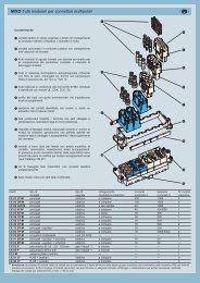
general overview of <strong>the</strong> multipole connec<strong>to</strong>r production for industrial purposes and accessoriesInsertsThe inserts are made of self-extinguishing <strong>the</strong>rmoplastic resin UL 94 V0, normally used for applications in a maximum ambience temperature of 125 °C. The specialversions for use with a maximum ambience temperature of 180 °C are made of PPS. Different conduc<strong>to</strong>r connection techniques are available: screw connections, crimpconnections, or flexible spring connections. The contacts are in silver or gold plated brass. The inserts are numbered on both sides by laser printing or moulded.There is a large number of versions of inserts selected on <strong>the</strong> basis of <strong>the</strong> rated voltage (from 50V <strong>to</strong> 5000V), <strong>the</strong> rated current (from 10A <strong>to</strong> 100A max), <strong>the</strong> number ofpoles, <strong>the</strong> different load combinations required (power and signal poles within <strong>the</strong> same insert).The inserts are approved in conformance with <strong>the</strong> major conformity marks including E.generalThe RoHS (2002/95/EC) and RAEE (2002/96/EC) Directives● The RoHS 2002/95/EC Directive bans <strong>the</strong> use of some harmful substances used in new electrical and electronic equipment commercially available from <strong>the</strong> 1st of July2006 (<strong>the</strong> exceptions for some applications are enclosed in <strong>the</strong> Directive Enclosure and in some later decisions made by <strong>the</strong> EU Commission 1)). The banned and/orrestricted substances are: Lead, Mercury, Cadmium, Hexavalent Chromium, Poly-Brominated By-Phenyls and Poly-Brominated Dy-Phenyl E<strong>the</strong>rs (PBB andPBDE respectively, fire retardant substances for <strong>the</strong>rmoplastic materials).● The RAEE 2002/96/EC Directive (with its later amendment 2003/108/EC) aims <strong>to</strong> recycle and reduce <strong>the</strong> waste produced by electrical and electronic equipment. It alsopromotes recycling and reusing such technological waste and establishes ambitious recovery rate targets, which vary according <strong>to</strong> <strong>the</strong> types of products involved. Themanufacturers or <strong>the</strong>ir agents in <strong>the</strong> EU must ensure that <strong>the</strong> equipment sold after <strong>the</strong> 13th of August 2005 listed in <strong>the</strong> Enclosure I A and illustrated in <strong>the</strong> Enclosure I Bof this Directive is collected, treated and recycled (<strong>the</strong> deadline varies from country <strong>to</strong> country. In Italy, <strong>the</strong> deadline has been postponed <strong>to</strong> 31/12/2007, awaiting forapproval by <strong>the</strong> required executive Ministerial Decrees).As a manufacturer of electrical equipment and components for industrial use, I.L.M.E. acknowledges <strong>the</strong> regulations introduced by <strong>the</strong>se Directives. The above mentionedDirectives are already effective in almost all EU countries. For <strong>the</strong> products described in this Catalogue, although <strong>the</strong> usage restriction of <strong>the</strong> above mentionedhazardous substances is not legally applicable (none of our product does in fact belong <strong>to</strong> any of <strong>the</strong> categories described and illustrated in <strong>the</strong> RoHS and RAEEDirectives), <strong>the</strong> “RoHS compliance” may become important and many of our cus<strong>to</strong>mers may require its compliance. We have <strong>the</strong>refore carried out <strong>the</strong> corrective actions,which have led <strong>to</strong> <strong>the</strong> “RoHS compliance” of all our products, wherever required. I.L.M.E. products sold after <strong>the</strong> 1st of July 2006 do not contain any of <strong>the</strong> restrictedsubstances in higher concentration than those allowed by <strong>the</strong> RoHS directive and by <strong>the</strong> later associated Decisions taken by <strong>the</strong> EU Commission.1) At <strong>the</strong> time of publication of this Catalogue, <strong>the</strong> following EU Commission Decisions were available: 2005/618/EC, of 18 August 2005, 2005/717/EC, of 13 Oc<strong>to</strong>ber2005, 2005/747/EC, of 21 Oc<strong>to</strong>ber 2005, 2006/310/EC, of 21 April 2006, 2006/690/EC, 2006/691/EC, 2006/692/EC, of 12 Oc<strong>to</strong>ber 2006.The heavy duty multipole connec<strong>to</strong>rs for industrial purposes are used in electric and electronic machinery, control units, electric panels, controlequipment and wherever connections are required for power and signalling circuits. (N.B. <strong>the</strong> connec<strong>to</strong>rs must not be handled live).The connec<strong>to</strong>rs are in conformance with <strong>the</strong> standard DIN VDE 0627 (European standard IEC 61984) and where applicable, <strong>to</strong> <strong>the</strong> standard DIN43652 (European standard EN 175301-801 developed by CENELEC TC48B).3
general overview of <strong>the</strong> multipole connec<strong>to</strong>r production for industrial purposes and accessoriesFire Safety Standards for <strong>the</strong> railway industrygeneralThe most advanced fire safety standards for <strong>the</strong> railway industry are <strong>the</strong> French standards:- NF F 16-101 Matériel roulant ferroviaire – Comportement au feu – Choix des matériaux- NF F 16-102 Matériel roulant ferroviaire – Comportement au feu – Choix des équipements électriqueswhich, in turn, refer <strong>to</strong> <strong>the</strong> test methods described in <strong>the</strong> following standards:- NF X 70 100 Analyse de gaz de pyrolyse et de combustion- NF X 10 702 Détermination de l'opacité des fumées en atmosphère non renouvelée<strong>the</strong> latter being very similar in methods <strong>to</strong> <strong>the</strong> following American standards:- ASTM E 662 Standard Test Method for Specific Optical Density of Smoke Generated by Solid Materials- ASTM E 162 Standard Test Method for Surface Flammability of Materials Using a Radiant Heat Energy Source.Equally as popular is <strong>the</strong> use of Bombardier Transportation <strong>to</strong>xicity specifications:- SMP 800-C Toxic Gas Generation.In Italy, since 2006, for installation on board of rolling-s<strong>to</strong>cks, certification of conformity <strong>to</strong> <strong>the</strong> new Italian railway standards (listed below) is required:- UNI CEI 11170-1:2005 Trains and trams – Fire safety guidelines for trains, trams and guide vehicles – General principles- UNI CEI 11170-2:2005 Trains and trams – Fire safety guidelines for trains, trams and guided vehicles – Design recommendations – Fire containment measures –Indication, moni<strong>to</strong>ring and evacuation systems- UNI CEI 11170-3:2005 Trains and trams - Fire safety guidelines for trains, trams and guided vehicles – Assessment of effect of fire on materials – Acceptable limitspublished by UNI and CEI <strong>to</strong>ge<strong>the</strong>r on 30/11/2005, in <strong>the</strong> delayed completion of <strong>the</strong> European standard relating <strong>to</strong> <strong>the</strong> effect of fire on materials <strong>to</strong> be installed on boardof rolling-s<strong>to</strong>cks, standard EN 45545, divided in 8 sections, only some of which have recently been published, after 16 years in <strong>the</strong> making, whilst <strong>the</strong> most crucial sectionsare still unfinished due <strong>to</strong> disagreements between <strong>the</strong> member countries (because of strong national interests, protectionism of domestic industries) especially inFrance, Germany, United Kingdom and Italy.To date, this planned standard, <strong>to</strong> be published as a simple TS (Technical Specification) and <strong>to</strong> be complied with on a voluntary basis, cannot yet be used and, as for <strong>the</strong>implementation of <strong>the</strong> Directives for <strong>the</strong> railway industry (interoperability of high-speed and conventional railways), <strong>the</strong> current national standards in force in <strong>the</strong> single EUmember states are regarded as equivalent in terms of safety.For Italy, <strong>the</strong> requirements for materials relating <strong>to</strong> electrical connec<strong>to</strong>rs are contained in <strong>the</strong> 2nd schedule “Acceptability criteria for electrical and electronic materials andcomponents” at <strong>the</strong> application “All o<strong>the</strong>r applications including inflammable materials” (all applications o<strong>the</strong>r than electric cables). For <strong>the</strong>se applications, four tests arerequired <strong>to</strong> be carried out on <strong>the</strong> materials:- The materials being affected by a small flame according <strong>to</strong> EN ISO 11925-2 with, according <strong>to</strong> <strong>the</strong> risk levels, for LR1 and LR2, a resistance <strong>to</strong> fire of <strong>the</strong> material of15s; for LR3 and LR4, a resistance of 30s.- Smokiness in compliance with French standard NF F 16-101 with IF better or equal <strong>to</strong> F2 for all risk levels. The material we use is classified as F1 (better than F2)according <strong>to</strong> <strong>the</strong> tests we carried out.- Fume optical density measurement, in compliance with French standard NF X 10-702 (from NF F 16-101) with values ≤ 100 for all risk levels LR1…4.- Toxicity measurement, in compliance with Italian standard CEI 20-37/7, with T ≤ 2 for all risk levels LR1…4.TestsIn 2006, we carried out labora<strong>to</strong>ry tests approved by <strong>the</strong> French Railways SNCF, according <strong>to</strong> <strong>the</strong> above mentioned French standards NF F 16-101 and NF F 16-102, <strong>the</strong>material we use in our connec<strong>to</strong>rs, which has been found <strong>to</strong> belong <strong>to</strong> class F1 (Index Fumée I.F. ≤ 20) as well as a <strong>to</strong>xicity index (Index Toxicité Fumée) I.T.C. = 20.Both <strong>the</strong>se values meet <strong>the</strong> requirements set out by <strong>the</strong> French standards and by <strong>the</strong> Italian standard UNI CEI 11170-3 schedule 2, which relates <strong>to</strong> electrical connec<strong>to</strong>rs.We have also commissioned a qualified North American labora<strong>to</strong>ry <strong>to</strong> carry out tests compliant with American standards, which have confirmed compliance with <strong>the</strong>requirements set out by <strong>the</strong> US Federal Transit Administration “Recommended Fire Safety Practices for Rail Transit Material Selection” for methods ASTM E 662 (NFPA258) (fume specific optical density), ASTM E 162 (ASTM D3635) (surface inflammability flame propagation index) and Bombardier Transportation SMP 800-C (fumesand gases <strong>to</strong>xicity).Test reports are available on request (please contact our Sales Offices).All requirements have been met.The connec<strong>to</strong>rs are suitable for use with alternate or direct current and facilitate <strong>the</strong> manufacture of sectional electric parts in complex machineryand installation and maintenance, in conformity with <strong>the</strong> European standard EN 60204-1. The connec<strong>to</strong>rs are designed for heavy duty industrialapplications.4
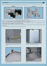
EnclosuresA large number of enclosure versions are available with different combinations of component materials, each one suitable <strong>to</strong> a specific installation: normal environmentalconditions, high temperature environments, aggressive environments and environments that require electromagnetic compatibility. The principal parts are made in die castaluminium alloy with a coating of epoxy-polyester powder or in self-extinguishing <strong>the</strong>rmoplastic (CK and MK series). They are resistant <strong>to</strong> impacts and strong mechanicalstress. The coupling stability and protection against accidental opening are assured by single or double closing devices comprising levers, springs and pegs in stainlesssteel or entirely in plastic (CK and MK series). Sealing is assured by special gaskets that protect <strong>the</strong> contact groups inside <strong>the</strong> enclosures against dust and aggressiveagents. In general, <strong>the</strong> coupled enclosures with <strong>the</strong> appropriate connections guarantee an IP66 (CEI EN 60529) degree of protection. Fur<strong>the</strong>rmore, <strong>the</strong> majority ofenclosures successfully complete <strong>the</strong> high pressure hot water jet test required by standard DIN 40050 - 9 with IP69K classification. A special, IP68 protection rated seriesis also available.generalOur enclosures have been certified by UL as Recognised Components for <strong>the</strong> USA and Canada (E mark) as accessories of our set of UL and CSA certified connec<strong>to</strong>rinserts (file UL E115072, file CSA 082270_0_000).The certification has been achieved by successfully completing several tests carried out in compliance with standard ANSI/UL 50 (Enclosures for Electrical Equipment)which is equivalent <strong>to</strong> <strong>the</strong> North American voluntary standard NEMA 250 (NEMA = National Electrical Manufactures Association) and <strong>to</strong> <strong>the</strong> equivalent Canadian standardCSA C22.2 No.94 (Special Purpose Enclosures) for safety levels used in North America and required by <strong>the</strong> local installation codes (ex.: NFPA 70 National Electrical Codein <strong>the</strong> US, CSA system standards for Canada); more specifically:- Type 12 (= NEMA 12): for indoor use, similar <strong>to</strong> IP54 protection rating in compliance with standard IEC/EN 60529;- Type 4 (= NEMA 4): for outdoor and indoor use, similar <strong>to</strong> IP66;- Type 4X (= NEMA 4X): for outdoor and indoor use, such as Type 4 + corrosion resistant, similar <strong>to</strong> IP66 protection rating.The certification includes all <strong>the</strong> enclosures belonging <strong>to</strong> <strong>the</strong> Standard (grey), W (green), R (red), S (EMC) and G (IP68) series of all sizes, with Pg, ISO and NPT cableexits, all special versions referable <strong>to</strong> standard types, as well as CKA enclosures.For fur<strong>the</strong>r information, please contact I.L.M.E. <strong>SpA</strong>.5
general overview of <strong>the</strong> multipole connec<strong>to</strong>r production for industrial purposes and accessoriesSupports, special enclosures and accessoriesThe supports, special enclosures and accessories provide <strong>the</strong> solution <strong>to</strong> <strong>the</strong> most diverse installation needs.The extensive range of articles comprises: panel supports for inserts, special enclosures (housing with double outlet, wide housings, housings withou<strong>to</strong>utlets (<strong>to</strong> be punctured, housings for round cables, hoods), insert combination blocks, accessories for CT inserts, interface for printed circuits, kitsfor control equipment, plates for mounting D-SUB inserts on<strong>to</strong> enclosures, reducing plates and closure plates, protection lid for transportation, codepins.general6
ToolsTo guarantee <strong>the</strong> efficiency and security of <strong>the</strong> connections a complete series of specific <strong>to</strong>ols is available for contact crimping that assure <strong>the</strong>maximum quality standards required by <strong>the</strong> standards.Manual or au<strong>to</strong>matic pneumatic <strong>to</strong>ols for heavy production are available, <strong>to</strong>ge<strong>the</strong>r with a complete series of complementary <strong>to</strong>ols for <strong>the</strong> mountingand dismounting of <strong>the</strong> contacts <strong>to</strong> be crimped.general7
general features of multipole connec<strong>to</strong>rs for industrial purposes general8
general features of multipole connec<strong>to</strong>rs for industrial purposes Threaded cable passage in various Pg diameters(types with pre-code ”C”) or metricpassage (types with pre-code ”M”) inaccordance with EN 60423, for cable entrydevices in accordance with EN 50262(NPT threading on request), may belocated vertically, horizontally or frontally. Heavy duty enclosures in die-castaluminium alloy or self-extinguishing<strong>the</strong>rmoplastic (CK and MK series).cRUus (E) certifiedWall mounting or bulkhead housings andhoods are available, with or without fixedcovers or with mobile protection covers.The types of enclosures CH-CA (Pg cableentries) and MH-MA (metric cable entries)have a tab that prevents <strong>the</strong> insertion ofinserts series CME (all) and CMCE (only16+2 poles), while CM (Pg) enclosuresseries and MM (metric) do not have anytabs and contain supplementary insulatingstrips inside. Stainless steel closure levers and springsguarantee a perfect closure and sealing. Locking device available in two versions,simple (with one lever), or double (with twolevers). Various types of handles are available: inself-extinguishing, <strong>the</strong>rmoplastic materialreinforced with glass fibres; in die-castaluminium (for special use with temperaturesof up <strong>to</strong> 180 °C); monoblock stainless steelhandles (CK, CZ, MK, MZ enclosures andfor special uses with temperatures of up <strong>to</strong>180 °C). Unlosable insert fastening screws, withantiloosening flexible washer. Contacts position identified with numbersor codes on both sides of each insert andlaser printed or moulded. Contacts in silver or gold-plated brasswith connections <strong>to</strong> <strong>the</strong> conduc<strong>to</strong>rs madevia unlosable unloosened screws, springterminal, crimping or incorporated 45°terminal block connec<strong>to</strong>rs (with screw orspring terminal). Earth terminal protection with wide contactsurface. Pegs and levers supplied with anti-frictionrings that facilitate closure and limit wearand tear. CE marking attesting conformity <strong>to</strong> <strong>the</strong>requirements of <strong>the</strong> Low Voltage directive73/23/EEC and its modification 93/68/EEC.general Metallic enclosures with a coated finish ofepoxy-polyester with high resistance <strong>to</strong>mechanical stress and external agents.Enclosures used with temperatures of up<strong>to</strong> 180 °C and in aggressive environmentsare treated with special coatings. Whereelectromagnetic compatibility is necessary:EMC enclosures with high conductivity andhigh corrosion resistance surfacetreatment. Inserts in self-extinguishing <strong>the</strong>rmoplasticmaterial reinforced with glass fibres, ULapproved, with a limit working temperaturefrom -40 °C <strong>to</strong> +125 °C.The inserts CME (all) and CMCE (only16+2 poles) for 830V have a key thatprevents <strong>the</strong> insertion of inserts for useo<strong>the</strong>r than that prescribed (types CM - Pgand MM - metric).For some series, inserts in PPS(polyphenylene sulphide) may berequested for special uses with temperaturesof up <strong>to</strong> 180 °C. Polarized inserts with asymmetric guiderails for preventing incorrect coupling.The inserts have a mechanical durationequal <strong>to</strong> or over 500 coupling cycles. Inserts manufactured in conformity withEN 61984 (DIN VDE 0627 standard andare certified and identified with <strong>the</strong> ULand CSA marks. Special seal gaskets in vinyl nitrile elas<strong>to</strong>meror fluoro elas<strong>to</strong>mer (on enclosures for usewith maximum temperatures of 180 °C andfor aggressive environments), in anti-aging,oil-resistant, fuel-resistant, <strong>to</strong>ge<strong>the</strong>r with<strong>the</strong> cable entry devices (not supplied)provide an IP66 degree of protection forcoupled connec<strong>to</strong>rs.Special conductive seals for EMC enclosures.9
standardsstandardsDimensioning of clearances and creepage distancesEuropean standard EN 61984 Ed. 1.0 (22001-11) was recently publishedfor safety prescriptions for multipole connec<strong>to</strong>rs for industrial uses and for<strong>the</strong> relevant tests. This standard assimilates, without any modifications, <strong>the</strong>corresponding international standard IEC 61984 Ed.1.0 (2001-06).It is applicable <strong>to</strong> connec<strong>to</strong>rs with rated voltage values of over 50V, and up<strong>to</strong> 1000V, and rated currents values of up <strong>to</strong> 125A per pole, for which nodedicated standard exists, or <strong>to</strong> which <strong>the</strong> particular specifications or <strong>the</strong>manufacturer refer as regards <strong>the</strong> safety aspects.For determining <strong>the</strong> minimum through-air and surface insulation distances,i.e. creepage distances, for connec<strong>to</strong>rs, this standard makes use (with somemodifications) of <strong>the</strong> concepts of standard IEC 60664-1 Ed. 1.0 (1992-10) 1) .NOTE - For connec<strong>to</strong>rs with rated voltage values of up <strong>to</strong> 50V - excludedfrom <strong>the</strong> field of application of Low Voltage Directive 73/23/EEC - standardEN 61984 may be used as a guide. For surface and through-air insulationdistances, refer <strong>to</strong> standard IEC 60664-1 Ed. (1992-10).We are illustrating below <strong>the</strong> method of standard EN 61984 for determiningminimum insulation values in connec<strong>to</strong>rs. The rated characteristics for eachILME connec<strong>to</strong>r family are provided on pages 14 and 15.The following are now obsolete: <strong>the</strong> insulation group concept, and <strong>the</strong>distinction of rated voltage values in<strong>to</strong> d.c. and a.c. voltage values 220Vand 380V were adapted <strong>to</strong> standardised values 230V and 400V according<strong>to</strong> IEC 60038 (2) and some concepts were taken from <strong>the</strong> regulations for LVelectrical systems of <strong>the</strong> IEC 60364 (3) series, as follows:- The overvoltage categories (I, II, III, IV), according <strong>to</strong> <strong>the</strong> use of <strong>the</strong>equipment (4) . They are correlated <strong>to</strong> <strong>the</strong> transient overvoltages taken as abasis for determining <strong>the</strong> rated impulse withstand voltage- The degrees of pollution- The classification of insulating materials according <strong>to</strong> <strong>the</strong>ir resistance <strong>to</strong>tracking- The conditions of <strong>the</strong> electrical field (homogenous or inhomogenous).Overvoltage categories (or impulse withstand)The overvoltage categories of a circuit or of an electrical system areidentified by a conventional number (from I <strong>to</strong> IV) based on <strong>the</strong> limit or <strong>the</strong>control of <strong>the</strong> assumed transient overvoltage values obtained on a circuit orelectrical system and depends on <strong>the</strong> means used <strong>to</strong> reduce <strong>the</strong>overvoltages.TABLE 1The rated impulse withstand voltage for equipment energised directly from<strong>the</strong> low-voltage mains (IEC 60664-1 Edition 1.0 1992-10)Nominal voltage of Voltage line <strong>to</strong> neutral Rated impulse withstand<strong>the</strong> supply system derived from nominal voltage b)based on IEC 60038 voltages a.c. or d.c.(CENELEC HD 472 S1, CEI 8-6)Overvoltage categoryV V ≤ V VThree phase a) Single phase I II III IV50 330 500 800 1500100 500 800 1500 2500120-240 150 800 1500 2500 4000230/400277/480} 300 1500 2500 4000 6000400 / 690 600 2500 4000 6000 80001000 1000 4000 6000 8000 12000a) The "/" symbol indicates a four-wire three phase distribution system (star distribution).The lower value is <strong>the</strong> voltage between phase and neutral (phase voltage), whereas <strong>the</strong>higher value is <strong>the</strong> voltage between <strong>the</strong> phases (mains voltage).Where only one value is indicated, it refers <strong>to</strong> three-wire, three-phase systems (deltadistribution) and specifies <strong>the</strong> line-<strong>to</strong>-line value.b) Equipment with <strong>the</strong>se rated impulse withstand values can be used in installations inaccordance with standard IEC 60364-4-443 (Italian standard CEI 64-8/4 Section 443, Germanstandard DIN VDE 0100-443).Table 1 supplies <strong>the</strong> rated impulse withstand voltage for equipment energiseddirectly from <strong>the</strong> low voltage mains in function of <strong>the</strong> rated voltage of <strong>the</strong> powersupply system, <strong>the</strong> relative voltage line-<strong>to</strong>-neutral and <strong>the</strong> overvoltage category.Industrial machinery and installations with fixed connection <strong>to</strong> <strong>the</strong> lowvoltage supply system and consequently <strong>the</strong> relative componentsincluding multipole connec<strong>to</strong>rs, constitute an example of <strong>the</strong> equipmentthat belongs <strong>to</strong> <strong>the</strong> overvoltage category III.Examples of general equipment that comes under overvoltage categoryII are electrical household appliances, portable <strong>to</strong>ols and o<strong>the</strong>r householdequipment or similar.For distribution networks with rated voltage of 230/400V (star distribution wi<strong>the</strong>ar<strong>the</strong>d neutral), and over-voltage category III (category III: impulse withstanding),<strong>the</strong> demanded rated impulse withstanding voltage is 4kV.For distribution networks with rated voltage of 400 or 500V (star distributionwithout neutral or with insulated neutral, or delta distribution, insulated orcorner-ear<strong>the</strong>d), and over-voltage category III (category III: impulse withstanding),<strong>the</strong> demanded rated impulse withstanding voltage is 6kV.(1) Assimilated with modifications as European Harmonisation Document HD 625.1 S1:1996and published by <strong>the</strong> CENELEC member countries as a national standard: Italian standardCEI 28-6 (1997-11), German standard DIN VDE 0110-1 (VDE 0110 Teil 1):1997-04.(2) Harminisation Document CENELEC HD 472 S1, Italian standard CEI 8-6, Germanstandard DIN IEC 38:1987-05.(3) Italian standard CEI 64-8, German standard DIN VDE 0100.(4) HD 625.1 S1 modifies <strong>the</strong> definition <strong>to</strong> "impulse withstanding categories".Degrees of pollutionPollution indicates <strong>the</strong> presence of any kind of foreign matter, whe<strong>the</strong>r solid,liquid or gaseous (ionised gas) that can have a negative influence on <strong>the</strong>dielectric strength or on <strong>the</strong> surface resistivity of <strong>the</strong> insulating material.The standard establishes four degrees of pollution. The categories areidentified by conventional numbers based on <strong>the</strong> quantity of pollutingagents or on <strong>the</strong> frequency of <strong>the</strong> phenomenon which determines <strong>the</strong>reduction of <strong>the</strong> dielectric strength and/or of <strong>the</strong> surface resistivity.Pollution degree 1:No pollution or only dry, non-conductive pollution.The pollution has no influence.Pollution degree 2:Only non-conductive pollution except that occasionally a temporaryconductivity caused by condensation may occur.Pollution degree 3:Conductive pollution or dry, non-conductive pollution which becomesconductive due <strong>to</strong> condensation which may occur.Pollution degree 4:The pollution generates persistent conductivity caused by conductive dus<strong>to</strong>r by rain or snow.Pollution degree 3 is typical of an industrial environment or similar, whilepollution degree 2 is typical of a household environment or similar.Standard EN 61984 permits <strong>the</strong> sizing of surface insulation distances ofconnec<strong>to</strong>rs installed in enclosures in protection class ≥IP54 for <strong>the</strong> degreeof pollution immediately below that of <strong>the</strong> application environment (e.g.: 2instead of 3).Extract from standard EN 619846.19.2.2 For a connec<strong>to</strong>r in protection class IP54 or higher, according <strong>to</strong>Publication IEC 60529, <strong>the</strong> insulating parts inside <strong>the</strong> enclosure may besized for a lower degree of pollution.This applies also <strong>to</strong> coupled connec<strong>to</strong>rs, closure of which is ensured by <strong>the</strong>connec<strong>to</strong>r enclosure, and which may be uncoupled for test and maintenancepurposes only.One may <strong>the</strong>refore use connec<strong>to</strong>rs installed in enclosures or containers inprotection class ≥IP54, at <strong>the</strong> rated data referring <strong>to</strong> degree pollution 2 inindustrial applications with degree of pollution 3, if, in compliance with <strong>the</strong>standard, <strong>the</strong> coupling of <strong>the</strong> connec<strong>to</strong>rs is opened only occasionally fortests or maintenance. In <strong>the</strong> event of temporary or limited duration inuncoupled state, a closing cover is, however, necessary, guaranteeing atleast protection class IP54. However, this does not apply <strong>to</strong> connec<strong>to</strong>rswhich remain uncoupled and exposed <strong>to</strong> an industrial atmosphere for anindefinite period. It should be noted, however, that pollution could penetrateinside coupled connec<strong>to</strong>rs, also when it comes from remote parts of <strong>the</strong>electrical system (e.g. through conduits providing cable entry <strong>to</strong> <strong>the</strong>connec<strong>to</strong>rs enclosure).Moreover, connec<strong>to</strong>r enclosures are usually supplied without cable entrydevices, with <strong>the</strong> installer fitting such devices according <strong>to</strong> need. Thedegree of protection marked on <strong>the</strong> enclosures is guaranteed only forconnec<strong>to</strong>rs coupled through <strong>the</strong> use of cable entry devices in equal orhigher IP protection class and expertly installed.Examples of application for <strong>the</strong> selection of degree of pollution 2 fora connec<strong>to</strong>r- connec<strong>to</strong>r on an electric mo<strong>to</strong>r controller, which is uncoupled only <strong>to</strong> replacea faulty mo<strong>to</strong>r, also in cases where degree of pollution 3 is insteadspecified for <strong>the</strong> system;- connec<strong>to</strong>r on a module-constructed machine, which is opened only fortransport purposes and which is used only for faster installation and forsafer putting in<strong>to</strong> service. One must make sure that <strong>the</strong> connec<strong>to</strong>r has notbeen polluted during transport. To ensure this has not occurred, protectivecovers or adequate packing must be used;- connec<strong>to</strong>r inside a panel in protection class ≥IP54. In this case one mayeven renounce equipping <strong>the</strong> connec<strong>to</strong>r with an IP54 enclosure.Insulating materialInsulating material influences <strong>the</strong> determination of <strong>the</strong> minimum creepagedistance. It is characterised according <strong>to</strong> <strong>the</strong> damage it suffers from <strong>the</strong>concentrated release of energy during scintillations when a surface leakagecurrent is interrupted due <strong>to</strong> <strong>the</strong> drying of <strong>the</strong> contaminated surface.The CTI (comparative tracking index), (index of resistance <strong>to</strong> surfacecurrents) is assumed as index of <strong>the</strong> resistance <strong>to</strong> creep currents of <strong>the</strong>insulating materials in <strong>the</strong> presence of atmospheric contaminating agents.The CTI constitutes <strong>the</strong> numeric value of <strong>the</strong> maximum voltage at which amaterial can resist against 50 drops of an electrolytic test solution withouttracking, i.e. without a progressive formation of conductive paths on <strong>the</strong>surface of <strong>the</strong> solid insulating material (and permanent electric arc between<strong>the</strong> electrodes of <strong>the</strong> test equipment) due <strong>to</strong> <strong>the</strong> combined effect ofelectrical stress and electrolytic contamination.The solid insulating materials are classified in<strong>to</strong> four groups:Group I 600 ≤ CTIGroup II 400 ≤ CTI < 600Group IIIa 175 ≤ CTI < 400Group IIIb 100 ≤ CTI < 175The values for groups IIIa/IIIb (Table 6, EN 61984) are identical for <strong>the</strong>purpose of determining <strong>the</strong> creepage distance values.The insulating materials used <strong>to</strong> manufacture <strong>the</strong> ILME multipoleconnec<strong>to</strong>rs belong <strong>to</strong> groups IIIa / IIIb.10
standardsElectric field conditionsThe insulation clearance is determined in Table 2 of IEC 60664-1, bearing in mind<strong>the</strong> following influencing fac<strong>to</strong>rs:- Rated impulse withstand voltage- Electric field conditions- Altitude: <strong>the</strong> values specified in Table 2 give sufficient impulse withstandcapability for equipment for use at altitudes up <strong>to</strong> 2.000 m. For equipment for useat higher altitudes, <strong>the</strong> corrective fac<strong>to</strong>rs specified in Table A2 of IEC 60664-1- The micro-environment.The shape and arrangement of <strong>the</strong> conductive parts influence <strong>the</strong> homogeneity of<strong>the</strong> electric field and consequently <strong>the</strong> clearance needed <strong>to</strong> withstand a givenvoltage. The clearances in Case A (inhomogeneous field) have <strong>the</strong> requiredimpulse withstand voltage under all conditions: clearances not less than thosespecified in Table 2 - Case A can be used irrespective of <strong>the</strong> shape and arrangemen<strong>to</strong>f <strong>the</strong> conductive parts and without verification by an impulse withstand test.Determination of clearancesIn accordance with standard IEC 60664-1, <strong>the</strong> following must be identified <strong>to</strong> determine it:a) The rated voltage of <strong>the</strong> power supply (usually 230/400V and <strong>the</strong>refore aconventional voltage line-<strong>to</strong>-neutral of 300V), in star distribution networkswith ear<strong>the</strong>d neutral, or 400V for star networks without neutral, or withinsulated neutral, or in networks with <strong>the</strong> distribution transformer'ssecondary winding delta connected, insulated or corner-ear<strong>the</strong>d and,<strong>the</strong>refore, with conventional phase voltage of 600V);b) The overvoltage category (usually III);c) The rated impulse withstand voltage determined from Table 1 of IEC 60664-1(usually 4 kV or 6kV)d) The type of electric field <strong>to</strong> which <strong>the</strong> parts through which <strong>the</strong> current flowsshall be subjected (worse case = inhomogenous field) and <strong>the</strong> degree ofpollution (usually 3).Standard EN 61984 specifies that <strong>the</strong> through-air insulation distance shouldbe sized according <strong>to</strong> Table 2 of IEC 60664-1, but according <strong>to</strong> <strong>the</strong> rated impulsewithstanding voltage obtained from Table 5 of EN 61984. The rated impulsewithstanding voltage must be selected according <strong>to</strong> <strong>the</strong> rated power supplyvoltage and <strong>to</strong> <strong>the</strong> overvoltage category. The assignment of connec<strong>to</strong>rs <strong>to</strong> aparticular overvoltage category (usually III) is effected according <strong>to</strong> <strong>the</strong> rules ofIEC 60664-1.Rated voltageThe voltage value assigned by <strong>the</strong> manufacturer <strong>to</strong> <strong>the</strong> connec<strong>to</strong>r and <strong>to</strong> which<strong>the</strong> operating and performance characteristics refer (IEC 60664-1, definition1.3.9 modified).NOTE – A connec<strong>to</strong>r may have more than one rated voltage value.As concerns <strong>the</strong> choice of <strong>the</strong> type of electric field, <strong>the</strong> through-air insulationdistances via windows and openings in <strong>the</strong> enclosures of insulating material,must comply with <strong>the</strong> values of case A in Table of IEC 60664-1. i.e. for nonuniform field conditions.TABLE 5Rated impulse withstand voltage (EN 61984 Edition 1.0 - 2001-11)Nominal voltage of <strong>the</strong> supply systemPreferred values for <strong>the</strong> ratedimpulse withstand voltage in kV(≤ rated insulation voltage of equipment) (1.2/50 μs)Overvoltage category *I II III IVa.c. a.c. a.c. a.c.voltage voltage voltage voltage(r.m.s. (r.m.s. (r.m.s. (r.m.s.value) value) value) value)Voltage line-<strong>to</strong>-earth derived from<strong>the</strong> nominal voltage of <strong>the</strong>supply system <strong>to</strong> <strong>the</strong> a.c. voltage(r.m.s. value) or d.c. voltaged.c.voltaged.c.voltageV V V V V kV kV kV kV100 66/115 66 60 - 0.5 0.8 1.5 2.5150 120/208; 115; 120; 110; 120 220-110; 0.8 1.5 2.5 4127/220; 127 240-120;300 220/380; 220; 230; 220 440-220 1.5 2.5 4 6230/400; 240; 260;240/415; 277;260/440;277/480;600 347/600 347; 380; 480 960-480 2.5 4 6 8380/660 400; 415;400/690 440; 480415/720 500; 577;480/830 600;1000 660; 690; 1000 - 4 6 8 12720; 830;1000;* Values for voltages ≤ 50V mentioned in IEC 60664-1, Encl. BWith <strong>the</strong> three values (b) (c) and (d) <strong>the</strong> minimum clearence is determined in Table 2 of IEC60664-1Special protected levelsLevel for electrical equipment(household and similar)Level for distributionsupply systemsInput levelTABLE 2*)Minimum clearance for insulation co-ordination (IEC 60664-1Edition 1.0 - 1992-10)RequiredMinimum clearances in air in mm.impulseup <strong>to</strong> 2.000 m. above sea levelwithstandvoltageCase A - inhomogenous field 1) Case B - homogenous field 2)degree of pollutiondegree of pollutionkV 1 2 3 4 1 2 3 40.33 3) 0.01 0.2 4) 5) 0.8 5) 1.6 5) 0.01 0.2 4) 5) 0.8 5) 1.6 5)0.40 0.02 0.2 4) 5) 0.8 5) 1.6 5) 0.02 0.2 4) 5) 0.8 5) 1.6 5)0.50 3) 0.04 0.2 4) 5) 0.8 5) 1.6 5) 0.04 0.2 4) 5) 0.8 5) 1.6 5)0.60 0.06 0.2 4) 5) 0.8 5) 1.6 5) 0.06 0.2 4) 5) 0.8 5) 1.6 5)0.80 3) 0.10 0.2 4) 5) 0.8 5) 1.6 5) 0.10 0.2 4) 5) 0.8 5) 1.6 5)1.0 0.15 0.2 4) 5) 0.8 5) 1.6 5) 0.15 0.2 4) 5) 0.8 5) 1.6 5)1.2 0.25 0.25 0.8 5) 1.6 5) 0.2 0.2 4) 5) 0.8 5) 1.6 5)1.5 3) 0.5 0.5 0.8 5) 1.6 5) 0.3 0.3 0.8 5) 1.6 5)2.0 1.0 1.0 1.0 1.6 5) 0.45 0.45 0.8 5) 1.6 5)2.5 3) 1.5 1.5 1.5 1.6 5) 0.6 0.6 0.8 5) 1.6 5)3.0 2 2 2 2 0.8 0.8 0.8 5) 1.6 5)4.0 3) 3 3 3 3 1.2 1.2 1.2 1.6 5)5.0 4 4 4 4 1.5 1.5 1.5 1.6 5)6.0 3) 5.5 5.5 5.5 5.5 2 2 2 28.0 3) 8 8 8 8 3 3 3 310.0 11 11 11 11 3.5 3.5 3.5 3.512.0 3) 14 14 14 14 4.5 4.5 4.5 4.51) Between pointed and flat electrode.2) When <strong>the</strong> clearance is less than <strong>the</strong> value indicated for Case A an impulsewithstand voltage test certificate is required3) Preferential values specified in Table 14) For printed wiring material, <strong>the</strong> values of degree of pollution 1 apply except that <strong>the</strong>value shall not be less than 0.04 mm as specified in Table 45) These minimum clearances given for pollution degrees 2, 3 and 4 are based onexperience ra<strong>the</strong>r than on fundamental data.*) Table 2 of IEC 60664-1 is modified in Variant 2. In particular, <strong>the</strong> columns referring<strong>to</strong> degree of pollution 4 have been eliminated. The definition of this degree is variedin 2.5.1 <strong>to</strong>: "permanent conductivity occurs, due <strong>to</strong> conductive dust, rain or o<strong>the</strong>rhumid conditions". The through-air insulation distances for degree of pollution 4area as specified for degree of pollution 3, with <strong>the</strong> exception that <strong>the</strong> minimumthrough-air distance is 1.6 mm.In 2.5.2 it is specified that "in conductive pollution conditions, <strong>the</strong> dimensions for <strong>the</strong>surface insulation distances cannot be specified where permanent conductivepollution is present, e.g.: due <strong>to</strong> coal or metal dust. On <strong>the</strong> contrary, <strong>the</strong> insulationsurface should be designed in order <strong>to</strong> prevent a seamless path of conductivepollution, e.g.: by means of ribs and cavities".The values written in bold are <strong>the</strong> most common multipole connec<strong>to</strong>rs forindustrial purposes.If <strong>the</strong> component respects <strong>the</strong> minimum through-air insulation distance prescribed for liveparts of opposing polarities, it is exempted from <strong>the</strong> impulsed voltage withstanding test.This test is run at sea level using increased voltage values in order <strong>to</strong> take in<strong>to</strong> accountrarefied air at high altitude (<strong>the</strong> prescribed values refer <strong>to</strong> 2000 m asl. However, if thisdistance is not respected, passing <strong>the</strong> test gives one <strong>the</strong> right <strong>to</strong> declare <strong>the</strong> relevant ratedimpulse withstanding voltage.Declaration of <strong>the</strong> rated impulse withstanding voltage is optional for standard EN 61984: if<strong>the</strong> manufacturer declares <strong>the</strong> rated impulse withstanding voltage, <strong>the</strong> impulse withstandingvoltage test is, in any event, necessary as dielectric verification. Alternatively, if <strong>the</strong>manufacturer does not declare this rated value, <strong>the</strong> voltage withstanding dielectric test atmains frequencies of 50/60 Hz for 60 s (test 4a of IEC 60512) is necessary, but at reducedvalues compared <strong>to</strong> <strong>the</strong> peak values of <strong>the</strong> impulsive test voltages of wave shapestandardised at 1.2/50 μs.To this end, standard EN 61984 provides <strong>the</strong> following cross-reference table:TABLE 8Test voltages (EN 61984 Edition 1.0 - 2001-11)Rated impulseTest voltageswithstand voltage Impulse withstand * Withstand voltagekV voltage (r.m.s. value)kV (1.2/50 μs)kV (50/60 Hz)at 2000 above sea level at sea level0.33 0.33 0.35 0.230.5 0.5 0.55 0.370.8 0.8 0.91 0.501.5 1.5 1.75 0.842.5 2.5 2.95 1.394 4 4.8 2.216 6 7.3 3.318 8 9.8 4.2612 12 14.8 6.6* If <strong>the</strong> test labora<strong>to</strong>ry is situated between sea level and an altitude of 2000 m asl,interpolation of test impulsed voltage is allowed.Rated impulse withstand voltageThe rated impulse withstanding voltage assigned by <strong>the</strong> manufacturer <strong>to</strong> <strong>the</strong>connec<strong>to</strong>r, which refers <strong>to</strong> <strong>the</strong> withstanding capacity of its insulation with respect <strong>to</strong>transient overvoltages [IEC 60664-1, definition 1.3.9.2 modified].Impulse withstand voltageThe highest peak value of a voltage impulse of prescribed shape and polarity, whichdoes not cause insulation faults under specified conditions.11standards
standardsDimensioning of creepage distancesThe minimum surface insulation distance (creepage distance), i.e. "<strong>the</strong> shortest distance along <strong>the</strong> surface of <strong>the</strong> insulation material between twoconducting parts" [IE 60664-1 development 1.3.3] for connec<strong>to</strong>rs is prescribed by standard EN 61984 in Table 6. It is determined according <strong>to</strong> ratedvoltage, degree of pollution and insulating material group. The rated voltage providing access <strong>to</strong> Table 6 (rationalised voltage of <strong>the</strong> feed system) isdetermined in Table 3a of IEC 60664-1 for single phase two or three wire a.c. or d.c. systems or Table 3b for three-phase three or four wire a.c. systems.Usually for three-phase systems with 230V/400V reted voltage, <strong>the</strong> conventional line-<strong>to</strong>-line insulation voltage is 400V and <strong>the</strong> line-<strong>to</strong>-earth for TT or TNsystems is 250V. For three-phase systems with 400V or 500V rated voltage <strong>the</strong> conventional line-<strong>to</strong>-line insulation voltage is respectively 400V and 500V.The degree of pollution must be specified according <strong>to</strong> standard IEC 60664-1. It strongly influences <strong>the</strong> rated insulation voltage of a connec<strong>to</strong>r. Therefore,<strong>the</strong> rated insulation voltage of a connec<strong>to</strong>r should be reconsidered time by time for each degree of pollution.standardsTABLE 3aSingle phase two or three wire a.c. or d.c.systems (IEC 60664-1 Edition 1.0 - 1992-10)TABLE 3bThree-phase three or four wire a.c. systems(IEC 60664-1 Edition 1.0 - 1992-10)Nominalvoltage of <strong>the</strong>supply system* )Voltages rationalisedfor Table 4for insulationline-<strong>to</strong>-line 1) line-<strong>to</strong>-earth 1)ABV V V12.5 12.5 -24 25 -25 25 -30 32 -42 50 -48 50 -50 ** ) 50 -60 63 -30-60 63 32100 ** ) 100 -110 125 -120 125 -150 ** ) 160 -220 250 -110-220 250 125120-240 250 125300 ** ) 320 -220-440 500 250600 ** ) 630 -480-960 1000 5001000 ** ) 1000 -Nominalvoltage of <strong>the</strong>supply system* )Voltages rationalisedfor Table 4for insulationline-<strong>to</strong>-line 1) line-<strong>to</strong>-earth 1)A C DV V V V63 63 32 63110 125 80 125120 125 80 125127 125 80 125150 ** ) 160 - 160208 200 125 200220 250 160 250230 250 160 250240 250 160 250300 ** ) 320 - 320380 400 250 400400 400 250 400415 400 250 400440 500 250 500480 500 320 500500 500 320 500575 630 400 630600 ** ) 630 - 630660 630 400 630690 630 400 630720 800 500 800830 800 500 800960 1000 630 10001000 ** ) 1000 - 1000Legenda:A = All systems.B = Single phase three-wire systems with mid-point ear<strong>the</strong>d.C = Three-phase four-wire systems [secondary winding of a star distributiontransformer] neutral-ear<strong>the</strong>d 2) .D = Three-phase three-wire systems [secondary winding of a delta distributiontransformer], unear<strong>the</strong>d 1) or corner-ear<strong>the</strong>d.1) The phase-earth insulation for unear<strong>the</strong>d or impedance-ear<strong>the</strong>d lines is equal <strong>to</strong>that between phases, because <strong>the</strong> operating voltage of any phase can, in practice,approach full voltage between <strong>the</strong> phases [line voltage]. This is because <strong>the</strong>actual voltage <strong>to</strong> earth is determined by <strong>the</strong> insulation resistance and by <strong>the</strong>capacitive reactance of each phase <strong>to</strong> earth. Consequently, a low (but acceptable)insulation resistance of a phase can, in effect, earth it and increase voltage <strong>to</strong>earth of <strong>the</strong> o<strong>the</strong>r two phases at full voltage between <strong>the</strong> phases [line voltage].2) For equipment for use on both three-phase three-wire and three-phase four wiresupplies, ear<strong>the</strong>d or unear<strong>the</strong>d, use only <strong>the</strong> values for three-wire systems.*) Assuming a rated voltage of <strong>the</strong> equipment.**) These values correspond <strong>to</strong> <strong>the</strong> values given in Table 1.With this voltage value, <strong>the</strong> pollution degree and <strong>the</strong> materials group <strong>the</strong> minimum creepage distance can be determined using Table 6.TABLE 6Minimum creepage distances (EN 61984 Edition 1.0 - 2001-11)RatedMinimum creepage distances (mm)voltagePollution degreer.m.s. value 1 2 3 4a.c or d.c. see note b Material group Material group Material groupV I a II III I II III c I II III c63 0.2 0.63 0.9 1.25 1.6 1.8 2 2.1 2.6 3.480 0.22 0.67 0.95 1.3 1.7 1.9 2.1 2.2 2.8 3.6100 0.25 0.71 1 1.4 1.8 2 2.2 2.4 3 3.8125 0.28 0.75 1.05 1.5 1.9 2.1 2.4 2.5 3.2 4160 0.32 0.8 1.1 1.6 2 2.2 2.5 3.2 4 5200 0.42 1 1.4 2 2.5 2.8 3.2 4 5 6.3250 0.56 1.25 1.8 2.5 3 3.5 4 5 6.3 7.5320 0.75 1.6 2.2 3.2 4 4.5 5 6 7.3 8.6400 1 2 2.8 4 4.5 5.3 6 7 8.5 10500 1.3 2.5 3.6 5 6 7 8 9 11 13630 1.8 3.2 4.5 6.3 8 9 10 11.1 13.6 16.1800 2.4 4 5.6 8 9 10.5 12 13.8 17 20.21000 3.2 5 7.1 10 12 14 16 17 21 25NOTE 1: The values for voltages ≤ 50V are supplied in IEC 60664-1, Table 4.NOTE 2: The values in bold are reduced compared <strong>to</strong> those of Table 4 IEC 60664-1, in compliance with 2.4 of IEC 60664-1.a Materials group I or materials group II, III, where <strong>the</strong> possibility of tracking is reduced in conformance with <strong>the</strong> conditions of paragraph 3.2 of IEC 60664-1.b Materials group I, II, IIIa, IIIbc Materials group IIIb is not recommended for application with pollution degree 3 above 630V and with pollution degree 4.12
feature of inserts for multipole connec<strong>to</strong>rsRecommended tightening <strong>to</strong>rque and size of screwdriversize of connec<strong>to</strong>r type tightening tightening recommended sizescrew <strong>to</strong>rque <strong>to</strong>rque of screwdriver(Nm) (Ib.in) (mm)M2.5 CT 40, 64 0.4 3.5 0.5x3M2.6 CTE 06...24 0.4 3.5 0.5x3Ø 2.9 CQ 04/2, CQ 08 0.7 6.2 Ph1M3 screw of earthing terminal series CQ 05, CQ 12 0.5 4.4 0.5x3M3 CDA 0.5 4.4 Ph0 or 0.6x3.5M3 CK, CKS, CD 07, CD 08, CQ 05, CQ 12 0.5 4.4 0.5x3M3 CN, CX 4/8 (16A) 0.5 4.4 0.6x3.5M3 CN..Q, CX 4/8 Q (16A) 0..5 4.4 Ph0M3 CNE, CME 0.5 4.4 Ph0 or 0.8x4M3 screw of small earthing terminal, MIXO frames series 0.5 4.4 Ph1 or 1.0x5.5M3 screw for fastening <strong>to</strong> enclosures, all series 0.5 4.4 Ph1 or 0.8x4M3,5 screw of earthing terminal series CDA, CDC 0.8 7.1 Ph1 or 1.0x5.5M4 screw of large earthing terminal, MIXO frames series 1.2 10.6 Ph1 or 1.0x5.5M4 CP 1.2 10.6 Ph1 or 0.8x4M4 screw of earthing terminal, all series except CDA, CDC, MIXO 1.2 10.6 Ph2 or 1.0x5.5M6 CX 4/... (80A) 2.5 22.1 1.0x5.5generalIncreasing <strong>the</strong> tightening <strong>to</strong>rque does not improve considerably <strong>the</strong> contacts resistances. The screw <strong>to</strong>rques are selected according <strong>to</strong> standardEN 60999-1, <strong>to</strong> provide excellent mechanical, <strong>the</strong>rmal and electric behaviour. The conduc<strong>to</strong>r or terminal may be damaged if <strong>the</strong> recommendedvalues are significantly exceeded.Stripping lenghtsinserts conduc<strong>to</strong>r section strippinglenghtconnection technique (mm 2 ) (AWG) (mm)ScrewCK 0.75÷2.5 18÷14 6CX 4/2 (16A) 0.75÷2.5 18÷14 7CN 0.75÷2.5 18÷14 7CNE 0.5÷2,5 20÷14 7CNE..X 0.25÷2.5 24÷14 7CDA 0.75÷2.5 18÷14 7CDA..X 0.25÷2.5 24÷14 7CTE 06...24 0.75÷2..5 18÷14 12CT 40 and 64 0.14÷2.5 26÷14 12CME 0.5÷2.5 20÷14 7CP 1.5÷6 16÷10 10,5CX 4/.. (80A) 4÷16 12÷5 14CrimpCDD, CD, MIXO (10A), CQ 12 0.14÷2.5 * 26÷14 8 (* 6 for 2.5 mm 2 )CCE, CDC, CMCE, CQ, CQE, MIXO (16A) 0.5÷4 20÷12 7,5CX, MIXO (40A) 1.5÷2.5 16÷14 94÷6 12÷10 9,6MIXO (100A) 16÷35 5÷2 15SpringCSE, CTSE 06...24, CMSE, MIXO (CX 05 S), CSS 0.14÷2.5 26÷14 9...11CTS 40/64 0.14÷2.5 26÷14 9...11non-prepared non-preparedmax 1 prepared max 18 preparedCKS 0.14÷2.5 26÷14 9...11non-prepared non-preparedmax 1.5 prepared max 16 prepared13
feature of inserts for multipole connec<strong>to</strong>rsinserts No. of poles 1) EN 61984 (2001-11) EN 61984 (2001-11) UL/CSA certifications 3)series pollution rating 3 pollution rating 2 certification 3)generalcodemain contacts + mauxiliary contactsnominal current 4)nominal voltageCK 3, 4 --- 10A 250V 4kV 3 230/400V 4kV 2 600V UL, CSA, CCC, GLCKS 3, 4 --- 10A 400V 4kV 3 600V (UL), (CSA)CD 8 (without m) --- 10A 50V 0.8kV 3 50V UL, CSA, CCC, GLCD 7, 15, 25, 40, (50), 64, (80), (128) --- 10A 250V 2) 4kV 3 230/400V 2) 4kV 2 600V UL, CSA, CCC, GLCT 40, 64 --- 10A 250V 4kV 3 230/400V 4kV 2 600V UL, CSA, CCC, GLCTS 40, 64 --- 10A 250V 4kV 3 230/400V 4kV 2 600V UL, CSA, CCC, GLCDD 24, 38, 42, 72, (76), 108, (144), (216) --- 10A 250V 4kV 2 600V UL, CSA, CCC, GLCQ 12 12 --- 10A 400V 6kV 3 400/690V 6kV 2 600V (UL), (CSA)CQ 05 5 --- 16A 230/400V 4kV 3 320/500V 4kV 2 600V UL, CSA, CCC, GLCQ 04/2 4 --- 40A 400/690V 6kV 3 600V cUL A)2 10A 250V 4kV 3CQ 08 8 --- 16A 500V 6kV 3 400/690V 6kV 2 600V cUL A) , CCCCDA 10, 16, (32) --- 16A 250V 4kV 3 230/400V 4kV 2 600V UL, CSA, CCC, GLCDC 10, 16, (32) --- 16A 250V 4kV 3 230/400V 4kV 2 600V UL, CSA, CCC, GLCQE 10, 18, 32, 46, (64), (92) --- 16A 500V 2) 6kV 3 830V 2) 8kV 2 600V UL, CSA, CCC, GLCCE 6, 10, 16, 24, (32), (48) --- 16A 500V 6kV 3 400/690V 6kV 2 600V UL, CSA, CCC, GLCN 6, 10, 16, 24, (32), (48) --- 16A 400V 4kV 2 600V UL, CSA, CCC, GLCNE 6, 10, 16, 24, (32), (48) --- 16A 500V 6kV 3 400/690V 6kV 2 600V UL, CSA, CCC, GLCSE 6, 10, 16, 24, (32), (48) --- 16A 500V 6kV 3 400/690V 6kV 2 600V UL, CSA, CCC, GLCSS 6, 10, 16, 24, (32), (48) --- 16A 500V 6kV 3 400/690V 6kV 2 600V UL, (CSA), CCCCTE (**) 6, 10, 16, 24 --- 16A 500V (**) 6kV 3 600V (UL), (CSA), CCC, GLCTSE 6, 10, 16, 24 --- 16A 500V 6kV 3 400/690V 6kV 2 600V UL, (CSA), CCC, GLCME 3, 6, 10, (12), (20), (32) --- 16A 830V 8kV 3 1000V 8kV 2 600V UL, (CSA), CCC720/1250V 8kV 216 --- 400/690V 6kV 32, (4) 500V 6kV 3CMSE 3, 6, 10, (12), (20) --- 16A 830V 8kV 3 1000V 8kV 2 600V UL, (CSA), CCC720/1250V 8kV 22, (4) 500V 6kV 3CMCE 3, 6, 10, (12), (20), (32) --- 16A 830V 8kV 3 1000V 8kV 2 600V UL, (CSA), CCC720/1250V 8kV 216 --- 400/690V 6kV 32, (4) 500V 6kV 3CP 6, (12) --- 35A 400/690V 6kV 3 600V UL, CSA, CCCCX 8/24 8 --- 16A 230/400V 4kV 3 400V 4kV 2 600V UL, CSA, CCC, GL24 10A 160V 2.5kV 3 250V 4kV 2CX 6/36 6 --- 40A 690V 8kV 3 600V UL, CSA, CCC, GL36 10A 160V 2.5kV 3 250V 4kV 2CX 12/2 12 --- 40A 690V 8kV 3 600V UL, CSA, CCC, GL2 10A 250V 4kV 3CX 4/0 4 0 80A 690V 8kV 3 600V UL, CSA, CCC, GLCX 4/2 4 --- 80A 690V 8kV 3 600V UL, CSA, CCC, GL2 16A 400V 6kV 3 400/690V 6kV 2CX 4/8 4 --- 80A 400V 6kV 3 400/690V 6kV 2 600V UL, CSA, CCC, GL8 16A 230/400V 4kV 3 400V 4kV 2pulsed holdingnominal voltagepollution ratingnominal voltagepulsed holdingnominal voltagepollution ratingnominal voltageAC or DC(**)= until s<strong>to</strong>cks of CT series connec<strong>to</strong>rs with nominal voltage 400V - 4kV - 2, UL, CSA certified lastN.B.: all inserts have a mechanical life equal <strong>to</strong> or higher than 500 mating cycles1) Polarities shown in brackets can be achieved by using two inserts.2) Contacts partially fitted inside an insert allow inserts <strong>to</strong> be used for applications requiring nominal voltages higher than those shown.See tables in page 38 (CD inserts), page 52 (CDD inserts) and page 73 (CQE inserts)3) Certifications shown in brackets are currently being applied for.4) Please check <strong>the</strong> insert load curves <strong>to</strong> establish <strong>the</strong> actual maximum operating current according <strong>to</strong> <strong>the</strong> ambient temperature.See diagrams from page 28 <strong>to</strong> page 34A) UL for USA and Canada14
feature of inserts for multipole connec<strong>to</strong>rsinserts contact insulation ambiance degree conduc<strong>to</strong>rresistance resistance temperature limit 5) of protection connections 6)(°C)code ≤ ≥ min max without enclosuresCK 1 mΩ 10 GΩ -40 +100 IP20 ✓CKS 1 mΩ 10 GΩ -40 +125 IP20 ✓CD 3 mΩ 10 GΩ -40 +125 IP20 ✓CD 3 mΩ 10 GΩ -40 +125 IP20 ✓CT 4 mΩ 10 GΩ -40 +125 IP20 ✓ ✓CTS 4 mΩ 10 GΩ -40 +125 IP20 ✓ ✓CDD 3 mΩ 10 GΩ -40 +125 IP20 ✓CQ 12 3 mΩ 10 GΩ -40 +125 IP20 ✓CQ 05 1 mΩ 10 GΩ -40 +125 IP20 ✓CQ 04/2 0.3 mΩ 10 GΩ -40 +125 IP20 ✓3 mΩCQ 08 1 mΩ 10 GΩ -40 +125 IP20 ✓CDA 1 mΩ 10 GΩ -40 +125 IP20 ✓CDC 1 mΩ 10 GΩ -40 +125 IP20 ✓CQE 1 mΩ 10 GΩ -40 +125 IP20 ✓CCE 1 mΩ 10 GΩ -40 +125 IP20 ✓CN 1 mΩ 10 GΩ -40 +125 IP20 ✓CNE 1 mΩ 10 GΩ -40 +125 IP20 ✓CSE 3 mΩ 10 GΩ -40 +125 IP20 ✓CSS 3 mΩ 10 GΩ -40 +125 IP20 ✓CTE (**) 4 mΩ 10 GΩ -40 +125 IP20 ✓ ✓CTSE 4 mΩ 10 GΩ -40 +125 IP20 ✓ ✓CME 1 mΩ 10 GΩ -40 +125 IP20 ✓axial screwscrewspring45° terminal blockcrimpgeneralCMSE 3 mΩ 10 GΩ -40 +125 IP20 ✓CMCE 1 mΩ 10 GΩ -40 +125 IP20 ✓CP 0.5 mΩ 10 GΩ -40 +125 IP20 ✓CX 8/24 1 mΩ 10 GΩ -40 +125 IP20 ✓3 mΩCX 6/36 0.3 mΩ 10 GΩ -40 +125 P20 ✓3 mΩCX 12/2 0.3 mΩ 10 GΩ -40 +125 IP20 ✓3 mΩCX 4/0 0.3 mΩ 10 GΩ -40 +125 IP20 ✓CX 4/2 0.3 mΩ 10 GΩ -40 +125 IP20 ✓1 mΩCX 4/8 0.3 mΩ 10 GΩ -40 +125 IP20 ✓1 mΩ(**)= until s<strong>to</strong>cks of CT series connec<strong>to</strong>rs with nominal voltage 400V - 4kV - 2, UL, CSA certified last5) It may be used with ambient temperatures up <strong>to</strong> 180 °C by using <strong>the</strong> insert special version made of PPS (polyphenilene solfide)6) See wires connection details on <strong>the</strong> next page.15
feature of inserts for multipole connec<strong>to</strong>rsinserts N. poles 1) EN 61984 (2001-11) EN 61984 (2001-11) UL/CSA certifications 3)pollution rating 3 pollution rating 2 certification 3)codemain contacts + mauxiliary contactsnominal current 4)nominal voltagepulsed holdingnominal voltagepollution ratingnominal voltagepulsed holdingnominal voltagepollution ratingnominal voltageAC or DCgeneralMIXOCX 02 G 2 (without m) --- 100A 1000V 8kV 3 920/1600V 8kV 2 600V cUL A) , CCC, GLCX 02 4A 2 (without m) (2.5 - 8 mm 2 ) --- 40A 1000V 8kV 3 1600V 12kV 2 600V (UL), (CSA)CX 02 4B 2 (without m) (6 - 10 mm 2 ) --- 40A 1000V 8kV 3 1600V 12kV 2 600V (UL), (CSA)CX 02 H 2 (without m) --- 16A 2900/5000V 15kV 3CX 03 4 3 (without m) --- 40A 400/690V (*) 6kV 3 600V UL, CSA, CCC, GLCX 05 S 5 (without m) --- 16A 400V 6kV 3 500V 6kV 2 600V UL, CSA, CCC, GLCX 06 C 6 (without m) --- 16A 500V 6kV 3 400/690V 6kV 2 600V UL, CSA, CCC, GLCX 08 C 8 (without m) --- 16A 400V 6kV 3 400/690V 6kV 2 600V UL, CSA, (CCC)CX 12 D 12 (without m) --- 10A 160V 2.5kV 3 250V 4kV 2 600V UL, CSA, CCC, GLCX 20 C 20 (without m) --- 16A 500V 6kV 3 830V 8kV 2 600V (UL), (CSA)CX P 2, 3 --- pneumatic contacts for up <strong>to</strong> 8 bar compressed air UL, CSA, CCC, GLCX 02 B 2 (***) (without m) --- --- 50V 0.8kV 3 (50V) UL, CSA, CCCCX 01 B 1 (+ screening) --- 10A 50V 0.8kV 3 (50V) UL, (CSA)CX 04 B 4 (+ screening) --- 10A 50V 0.8kV 3 (50V) UL, CSA, CCCCX 01 J 1 RJ45 insert (without m) (UL), (CSA)4 10A 250V 4kV 3CX 02 J 2 RJ45 inserts (without m) (UL), (CSA)8 10A 250V 4kV 3(*)= with up <strong>to</strong> 5 mm section cable(***)= CX 04 B (4P) multiaxial connec<strong>to</strong>rs or CX 01 B coaxial connec<strong>to</strong>rN.B. all inserts have a mechanical life equal <strong>to</strong> or higher than 500 mating cycles1) Polarities shown in brackets can be achieved by using two inserts.3) Certifications shown in brackets are being applied for.4) Please check <strong>the</strong> insert load curves <strong>to</strong> establish <strong>the</strong> actual maximum operating current according <strong>to</strong> <strong>the</strong> ambient temperature.See diagrams from page 34 <strong>to</strong> page 35A) UL for USA and CanadaNominal DataNominal data complies with requirements of EN 61984 standard.Marking example <strong>to</strong> be applied only in a mains power supply with insulated neutral or with neutral <strong>to</strong> earth in a corner (seeTable 5, EN 61984):Nominal current --------------------------------------------------------------------------Nominal voltage line-<strong>to</strong>-neutral ---------------------------------------------------------------Nominal voltage line-<strong>to</strong>-line -----------------------------------------------------------------------10A 230/400V 4kV 3Pulsed holding nominal voltage ---------------------------------------------------------------------------Pollution rating -----------------------------------------------------------------------------------------------------------Marking example <strong>to</strong> be applied in any mains power supplies, including those with insulated neutral and <strong>the</strong> delta power supplies with earthin a corner (see Table 5, EN 61984):Nominal current --------------------------------------------------------------------------Nominal voltage ------------------------------------------------------------------------------------16A 500V 6kV 3Pulsed holding nominal voltage ---------------------------------------------------------------------------Pollution rating -----------------------------------------------------------------------------------------------------------16
feature of inserts for multipole connec<strong>to</strong>rsinsert series contactresistanceinsulationresistanceambienttemperature limits 5) protectionratingwirer connection 6)(°C)withoutcode ≤ ≥ min max enclosuresaxial screwscrewspringconnection blockat 45°crimpMIXOCX 02 G 0.3 mΩ 10 GΩ -40 +125 IP20 ✓CX 02 4A 0.5 mΩ 10 GΩ -40 +125 IP20 ✓CX 02 4B 0.5 mΩ 10 GΩ -40 +125 IP20 ✓CX 02 H 1 mΩ 10 GΩ -40 +125 IP20 ✓CX 03 4 0.3 mΩ 10 GΩ -40 +125 IP20 ✓CX 05 S 3 mΩ 10 GΩ -40 +125 IP20 ✓CX 06 C 1 mΩ 10 GΩ -40 +125 IP20 ✓CX 08 C 1 mΩ 10 GΩ -40 +125 IP20 ✓CX 12 D 3 mΩ 10 GΩ -40 +125 IP20 ✓CX 20 C 1 mΩ 10 GΩ -40 +125 IP20 ✓CX P -40 +125 IP20 couplingCX 02 B --- 10 GΩ -40 +125 IP20 couplingCX 01 B 3 mΩ 10 GΩ -40 +70 IP20 ✓CX 04 B 3 mΩ 10 GΩ -40 +70 IP20 ✓CX 01 J -20 +120 IP20 ✓3 mΩ 10 GΩ -20 +120 IP20CX 02 J -20 +120 IP20 ✓3 mΩ 10 GΩ -20 +120 IP20general5) It may be used with ambient temperatures up <strong>to</strong> 180 °C by using <strong>the</strong> insert special version made of PPS (polyphenilene solfide)6) See wire connection details on <strong>the</strong> next page.17
conduc<strong>to</strong>r connectionscontacts with screw terminal connectionswith or without wire protectionscrew connected contacts in built-interminal blockgeneraldescription description descriptionThe different types of conduc<strong>to</strong>r connections <strong>to</strong> <strong>the</strong>male and female inserts are described on <strong>the</strong> right.The types are summarised as follows:- screw terminals- spring connection terminals- connec<strong>to</strong>rs with incorporated terminal block- crimp terminalsN.B.:for all inserts with screw terminals it is importantthat <strong>the</strong> right <strong>to</strong>rsional <strong>to</strong>rque is applied <strong>to</strong> <strong>the</strong>screws in order <strong>to</strong> prevent wrong contacts ordamage <strong>to</strong> <strong>the</strong> conduc<strong>to</strong>r, <strong>the</strong> screw or <strong>the</strong> terminal(see data mentioned in <strong>the</strong> inserts pages).inserts: CK - CDA - CN - CNE - CME - CP - CXThe connections of <strong>the</strong> conduc<strong>to</strong>rs <strong>to</strong> <strong>the</strong> female andmale inserts is made via screws (in accordance withstandard EN 60999-1).Two different types of clamping are possible:- with wire protection that does not require preparationof <strong>the</strong> conduc<strong>to</strong>rs- without wire protection that requires <strong>the</strong> conduc<strong>to</strong>rs<strong>to</strong> be prepared with bush terminalsinsert series: CTEIn this layout <strong>the</strong> wires are connected <strong>to</strong> <strong>the</strong> socket andplug insert contacts by means of a screw for all CTEinserts (in compliance with EN 60999-1).The inserts contain:- a terminal block at 45° for fixed installation onelectrical panels or on built-in DIN EN 60715 rail, foreasier wire cabling and identification operations- screw connection with pressure plate which does notrequire <strong>the</strong> wires <strong>to</strong> be prepared (CTE inserts).The 10A and 16A crimp contacts are available ei<strong>the</strong>rsilver or gold-plated.The gold-plated crimp contacts are recommended forapplications with very low rated currents and ratedvoltages.Thanks <strong>to</strong> <strong>the</strong> conduction characteristics of gold, <strong>the</strong>deterioration of signals is prevented and an excellentresidence <strong>to</strong> <strong>the</strong> superficial oxidation of <strong>the</strong> contacts isobtained.Gold-plated contacts are recommended with signalswith ±5 mA current and ±5V voltage.with wire protectionwithout wire protectionCTE insert connectioninserts: CX..A / CX..BThe connections of <strong>the</strong> conduc<strong>to</strong>rs <strong>to</strong> <strong>the</strong> female andmale inserts is made via screws (in accordance withstandard.Fully insert <strong>the</strong> wire in <strong>the</strong> back of <strong>the</strong> contact; insert a2mm hexagonal key in <strong>the</strong> front of <strong>the</strong> contact and tightenby holding down <strong>the</strong> cable.CX 02modular insert2 mmhexagonalkeywire18
conduc<strong>to</strong>r connectionscontacts connected with spring terminal, contacts connected with contacts connected within built-in terminal block dual spring terminal spring terminalgeneraldescription description descriptioninsert series: CTSE- CTSWith terminal block at 45° built-in for fixed installationon electrical panels or on built-in DIN EN 60715 rail, foreasier wire cabling and identification operations.Spring terminal connection which does not require wirepreparation (CTSE inserts).A screwdriver with a 3.5 x 0.5 mm blade is <strong>the</strong> only <strong>to</strong>olrequired <strong>to</strong> insert <strong>the</strong> wire in <strong>the</strong> contact.CTSE insert connectioninsert series: CSSEquipped with two terminals per contact. This type ofconnection allows a circuit <strong>to</strong> be branched off.A screwdriver with a 3.5 x 0.5 mm blade is <strong>the</strong> only <strong>to</strong>olrequired <strong>to</strong> insert <strong>the</strong> wire in <strong>the</strong> contact.insert series: CSE - CMSEIn this layout <strong>the</strong> wires are connected <strong>to</strong> <strong>the</strong> socket andplug insert contacts by means of a spring terminal.This type of connection offers <strong>the</strong> following advantages:- no special wire preparation- a screwdriver with a 3.5 x 0.5 mm blade is <strong>the</strong> only<strong>to</strong>ol required <strong>to</strong> insert <strong>the</strong> wire in <strong>the</strong> contact.- it offers an excellent fastening solution and a greatresistance <strong>to</strong> strong vibrations.- allows rigid and flexible wires with sections between0.14 and 2.5 mm 2 <strong>to</strong> be used- allows conductibility tests under load <strong>to</strong> be carriedout through <strong>the</strong> screwdriver insertion section, withoutsplitting <strong>the</strong> insert.- greatly reduces insert preparation and cabling times.Spring terminal connection operating principlesstage 1when <strong>the</strong> screwdriver is inserted in<strong>the</strong> square housing provided, <strong>the</strong>wire housing in <strong>the</strong> spring isopened.stage 3when <strong>the</strong> screwdriver is removed,<strong>the</strong> spring is held down on <strong>the</strong>inserted wire.stage 2<strong>the</strong> wire is pushed all <strong>the</strong> way in<strong>the</strong> round housing provided.stage 4<strong>the</strong> connection is complete; pull on<strong>the</strong> wire <strong>to</strong> make sure that <strong>the</strong>spring firmly holds down <strong>the</strong> wire.19
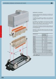
conduc<strong>to</strong>r connectionsRemovable crimp contacts Removable crimp contacts Removable crimp contacts(with retainer device) (with retainer device on contacts) (with retainer device inside insert)generaldescription description descriptioninserts: MIXO 100AThis layout enables <strong>the</strong> wires <strong>to</strong> be connected <strong>to</strong> <strong>the</strong>socket and plug insert removable contacts by crimping<strong>the</strong>m with a crimp <strong>to</strong>ol and its locating turret.This innovative insert design, patented by ILME,allows crimped contacts <strong>to</strong> be quickly fitted and removed.The special plates provided fasten <strong>the</strong> contact holder;after <strong>the</strong> insert has been mated <strong>to</strong> <strong>the</strong> o<strong>the</strong>r inserts andis inserted in <strong>the</strong> MIXO frame, connection is ensuredand is extremely resistant even <strong>to</strong> <strong>the</strong> mostinsidious strains, such as vibrations. Contacts can beremoved without having <strong>to</strong> use any specific <strong>to</strong>ols,but by simply using a screwdriver.inserts: CD - CDD - CX - MIXOThe connections of <strong>the</strong> conduc<strong>to</strong>rs <strong>to</strong> <strong>the</strong> removablecontacts of <strong>the</strong> male and female inserts are made viacrimping with a crimping <strong>to</strong>ol and loca<strong>to</strong>r.The crimped connections are <strong>the</strong>n inserted (with afitting <strong>to</strong>ol for sizes 1 and 2, without any <strong>to</strong>ols for sizes2, 3, 4 and 5) in <strong>the</strong> above mentioned sizes and arekept firmly in place by means of <strong>the</strong> flexible devicefitted on <strong>the</strong> contacts. The wire housing entry on <strong>the</strong>contact is tapered <strong>to</strong> facilitate wire insertion and <strong>to</strong>avoid any damages occurring after <strong>the</strong> crimpingoperation. To remove connections, a special extrac<strong>to</strong>r<strong>to</strong>ol must be used.inserts:CQ - CQE - CCE - CDC - CMCE - CX - MIXOThe connections of <strong>the</strong> conduc<strong>to</strong>rs <strong>to</strong> <strong>the</strong> removablecontacts of <strong>the</strong> male and female inserts are made viacrimping with a crimping <strong>to</strong>ol and loca<strong>to</strong>r.The crimped connections are <strong>the</strong>n introduced (withouthaving <strong>to</strong> use any <strong>to</strong>ol, except for size 1, which requires<strong>the</strong> use of a fitting <strong>to</strong>ol) in <strong>the</strong> inserts of <strong>the</strong> abovementioned series and are firmly held in place bymeans of a retainer device fitted on <strong>the</strong> insert whichholds down <strong>the</strong> contact.The contact can be removed by simply using a fla<strong>the</strong>ad 3mm screwdriver through <strong>the</strong> openings providedin <strong>the</strong> inserts (CDC, CMCE 16+2, CX 8/24 series) or bymeans of special extrac<strong>to</strong>r <strong>to</strong>ols, <strong>to</strong> unlock <strong>the</strong> retainerdevice and release <strong>the</strong> contact (CQ, CCE, CMCE,CQE, CX, MIXO series).The wire housing entry on <strong>the</strong> contact is tapered <strong>to</strong>facilitate wire insertion and <strong>to</strong> avoid any damagesoccurring after <strong>the</strong> crimping operation.10A max contactsconduc<strong>to</strong>r sectionnumber(mm 2 ) AWG identification16A max contactsconduc<strong>to</strong>r sectionthroat(mm 2 ) AWG identification0.14 ÷ 0.37 26 ÷ 2210.5 200.5 2020.75 180.75 1821 181 1831.5 161.5 1642.5 142.5 1454 12Contacts are supplied in <strong>the</strong> silver or gold plated versionThe contacts are supplied in <strong>the</strong> silver or gold platedversion. Male contacts in <strong>the</strong> “advanced” (shortenedcontact) version can also be supplied.100A max contactswire sectionidentification(mm 2 )AWG16 6 - 5 Ø hole 5.5 mm25 4 - 3 Ø hole 7.0 mm35 2 Ø hole 7.9 / 8.2 mmContacts are supplied in <strong>the</strong> silver plated version only40A max contactsconduc<strong>to</strong>r sectionidentification(mm 2 )AWG1,5 16 Ø hole 1,75 mm2,5 14 Ø hole 2,25 mm4 12 Ø hole 2,85 mm6 10 Ø hole 3,5 mmThe contacts may be supplied silver plated only20
enclosures versions and applicationsstandard versioninsulated 830V versiongeneraldescriptiondescriptionChangeover from Pg threads <strong>to</strong> M metric threadsAfter 31st December 1999, <strong>the</strong> German safetystandard DIN VDE 0619 (1987-09) and <strong>the</strong>standards it refers <strong>to</strong> - DIN 46319 for dimensionswith metric threads and DIN 46320 (T1-T4), DIN46255 and DIN 46259 for dimensions with Pgthreads (Pg= Panzerrohr-Gewinde: literally"threads for armoured pipes") - were withdrawn andEuropean standard EN 50262 "Metric cablegrippers for electrical installations" has been inforce since 1st January 2000. This standard defines<strong>the</strong> new sizes with metric threads for cable grippersaccording <strong>to</strong> EN 60423 and establishes <strong>the</strong> safetyprescriptions. Conversely, it does not specify <strong>the</strong>dimensions, such as <strong>the</strong> size of <strong>the</strong> tighteningwrench, <strong>the</strong> diagonal dimension, or <strong>the</strong> dimensionsof <strong>the</strong> tightness seals, as was <strong>the</strong> case in <strong>the</strong>withdrawn DIN for Pg cable grippers.The standard came definitively in<strong>to</strong> force on 1stApril 2001, when <strong>the</strong> contrasting national standardswere withdrawn. It is valid in all member countriesof CENELEC (European Electrical StandardisationCommittee) and its publication has led <strong>to</strong> a broadeningof <strong>the</strong> supply of enclosures for multi-pole connec<strong>to</strong>rsfor industrial use, <strong>to</strong> include new enclosureversions with cable entry suitable for metric cablegrippers. Cable gripper producers have introduced<strong>the</strong> new metric series <strong>to</strong> add <strong>to</strong> <strong>the</strong> Pg size series,<strong>to</strong> gradually replace <strong>the</strong> latter type. The transitionperiod indicated in <strong>the</strong> new standard should haveended on 1st March 2001, after which date <strong>the</strong> useof entry devices for Pg cables and, as a result,enclosures with Pg thread, should have ended innew installations. Never<strong>the</strong>less, both <strong>the</strong> cableentry devices and <strong>the</strong> relevant enclosures with Pgthread, may continue <strong>to</strong> be used as spare parts.For <strong>the</strong> CE marking of <strong>the</strong>se items, observance of<strong>the</strong> safety conditions specified by <strong>the</strong> Low VoltageDirective is sufficient. To distinguish mobile andfixed wall-mounted enclosures with metric outletsfrom <strong>the</strong> relevant Pg versions (marked with a Cpre-code), <strong>the</strong> ILME metric types are marked withan M pre-code.The transposition table below indicates <strong>the</strong>correspondence rule adopted in most cases byILME for creating <strong>the</strong> new metric versions.Transposition Pg ➔ metricPgmetricPg 11 M 20Pg 13.5 M 20Pg 16 M 20Pg 21 M 25Pg 29 M 32Pg 36 M 40Pg 42 M 50This series has been developed for applicationin electric and electronic machinery, controlunits, electric panels, control equipment, industrialenvironments, and in general, wherever asectional and reliable connection is required forpower and signal circuits.The inserts of <strong>the</strong> CMCE series (excepting <strong>the</strong>16+2 poles) and of <strong>the</strong> CMSE series may usestandard enclosures also for uses of up <strong>to</strong> 830V.UL certified for USA and Canada for NEMA 4,NEMA 4X and NEMA 12 protection ratings,printed on <strong>the</strong> packaging.IP65, IP66 and IP69K protection ratings (IP44and IP67 for CK and MK series).Note: <strong>the</strong> enclosures are currently printed with<strong>the</strong> wording IP65.Characteristics of <strong>the</strong> materials used:CK, MK and CQ series- in self-extinguishing grey RAL 7035 or black<strong>the</strong>rmoplastic material for insulating enclosures(in <strong>the</strong> CQ version, only available in black) ormetallic enclosures- metallic enclosures with epoxy-polyester powdercoating- gaskets in anti-aging, oil-resistant, greaseresistantand fuel-resistant vinyl nitrile elas<strong>to</strong>mer- monoblock locking device in stainless steel orgalvanised stainless steel for metallic enclosures- monoblock locking device in self-extinguishing<strong>the</strong>rmoplastic material for insulating enclosuresCZ, CH, CA and MZ, MH, MA, MF, MZF series- In die-cast aluminium alloy- with epoxy-polyester powder coating- gaskets in anti-aging, oil-resistant, greaseresistantand fuel-resistant vinyl nitrile elas<strong>to</strong>mer- locking device with levers, springs and pegs instainless steel- monoblock lever handles in stainless steel (forCZ and MZ enclosures)- lever handles in self-extinguishing <strong>the</strong>rmoplasticmaterial reinforced with glass fibres, UL approved(for CH, CA and MH, MA enclosures)Applications as for <strong>the</strong> standard version.The enclosures do not have tabs and allow <strong>the</strong>insertion of inserts with rated voltage up <strong>to</strong> 830V(series CME).The enclosures contain supplementary insulatingstrips inside.UL certified for USA and Canada for NEMA 4,NEMA 4X and NEMA 12 protection ratings,printed on <strong>the</strong> packaging.IP65, IP66 and IP69K protection ratings.Note: <strong>the</strong> enclosures are currently printed with<strong>the</strong> wording IP65.Characteristics of <strong>the</strong> materials used:CM, CMA and MM, MMA, MMF series- In die-cast aluminium alloy- with epoxy-polyester powder coating- gaskets in anti-aging, oil-resistant, greaseresistantand fuel-resistant vinyl nitrile elas<strong>to</strong>mer- locking device with levers, springs and pegs instainless steel- lever handles in self-extinguishing <strong>the</strong>rmoplasticmaterial reinforced with glass fibres, UL approved- supplementary insulation inside enclosures21
enclosures versions and applications180 °C version version for EMC versionaggressive environmentsgeneraldescription description descriptionThis series has been developed for industrialapplications where <strong>the</strong> ambient temperaturesare particularly harsh (from -40 °C <strong>to</strong> +180 °C).The enclosures do not have any internal tabsand allow insertion of <strong>the</strong> CME inserts.These enclosures have supplementary insulatingstrips inside.These enclosures are for use with inserts inself-extinguishing <strong>the</strong>rmoplastic material (PPSpolyphenylene sulphide).This version is distinguished by <strong>the</strong> red colour of<strong>the</strong> enclosures.UL certified for USA and Canada for NEMA 4,NEMA 4X and NEMA 12 protection ratings,printed on <strong>the</strong> packaging.IP65, IP66 and IP69K protection ratings.Note: <strong>the</strong> enclosures are currently printed with<strong>the</strong> wording IP65.This series has been developed for industrialapplications with particularly aggressive externalagents (e.g. salt atmospheres or ambients, etc.).The enclosures do not have any internal tabsand allow insertion of <strong>the</strong> CME inserts.These enclosures have supplementary insulatingstrips inside.The version can easily be identified by <strong>the</strong> greencolour of <strong>the</strong> enclosures.UL certified for USA and Canada for NEMA 4,NEMA 4X and NEMA 12 protection ratings, printedon <strong>the</strong> packaging.IP65, IP66 and IP69K protection ratings.Note: <strong>the</strong> enclosures are currently printed with<strong>the</strong> wording IP65.This series has been developed for industrialapplications that require electromagnetic compatibility(EMC, Electromagnetic Compatibility),in accordance with <strong>the</strong> European standards thatregulate <strong>the</strong> emission and immunity of <strong>the</strong>equipment.UL certified for USA and Canada for NEMA 4,NEMA 4X and NEMA 12 protection ratings,printed on <strong>the</strong> packaging.IP65, IP66 and IP69K protection ratings.Note: <strong>the</strong> enclosures are currently printed with<strong>the</strong> wording IP65.Characteristics of <strong>the</strong> materials used:CZ..R, CH..R, CA..R andMZ..R, MH..R, MA..R series- in die-cast aluminium alloy- chromate treated die cast treatment- coated with special <strong>the</strong>rmoset powder with highresistant <strong>to</strong> high temperatures- gaskets in anti-aging fluoro elas<strong>to</strong>mer- locking device with levers, springs and pegs instainless steel- monoblock levers in stainless steel (for CZ..R,CH..R 48 and MZ..R, MH..R 48 versions)- lever handles in aluminium with specialdie-cast coating (for CH..R 10, 16, 24 andMH..R 10, 16, 24 versions)- supplementary insulation inside enclosuresCharacteristics of <strong>the</strong> materials used:CK..W and MK..W series- chromate treated die cast treatment- coated with epoxy-polyester powder- gaskets in fluoro elas<strong>to</strong>mer- monoblock locking device in stainless steelCZ..W, CH..W, CA..W seriesand MZ..W, MH..W, MA..W- in die-cast aluminium alloy- chromate treated die cast treatment- coated with epoxy-polyester powder- gaskets in anti-aging fluoro elas<strong>to</strong>mer- locking device with levers, springs and pegs instainless steel- pegs in stainless steel- monoblock levers in stainless steel (for CZ..Wand MZ..W enclosures)- lever handles in self-extinguishing <strong>the</strong>rmoplasticmaterial reinforced with glass fibres, UL approved(CH..W, CA..W and MH..W, MA..W versions)- supplementary insulation inside enclosuresCharacteristics of <strong>the</strong> materials used:CK..S and MK..S series- chromate treated die cast treatment with highsurface conductivity- special gaskets in highly conductive material- monoblock locking device in stainless steelCZ..S, CH..S, CA..S andMZ..S, MH..S, MA..S series- in die-cast aluminium alloy- chromate treated die cast treatment with highsurface conductivity- special gaskets in highly conductive material- locking device with levers, springs and pegs instainless steel- lever handles in self-extinguishing <strong>the</strong>rmoplasticmaterial reinforced with glass fibres, UL approved22
enclosures versions and applicationshigh protection IP68 versionsingle lever central position versiongeneraldescriptiondescriptionFor applications in <strong>the</strong> railway sec<strong>to</strong>r andwhenever <strong>the</strong> following characteristics aredemanded: high pressure, impact and corrosionresistance, in protection class IP68. Moreover,<strong>the</strong>y provide good electromagnetic screening.The IP68 protection class marked on <strong>the</strong>enclosure is guaranteed subject <strong>to</strong> expertinstallation and use of cable entry devices wi<strong>the</strong>qual or better characteristics.This series was specifically made for industrialapplications with limited installation space.These enclosures can be installed, placed sideby-sideand handled in a single operation.Fur<strong>the</strong>rmore, <strong>the</strong> lever's shape reduces <strong>the</strong>effort required <strong>to</strong> uncouple <strong>the</strong> inner fittings.UL certified for USA and Canada for NEMA 4,NEMA 4X and NEMA 12 protection ratings,printed on <strong>the</strong> packaging.IP69K protection rating for tightness <strong>to</strong> pressurizedwater jets.Characteristics of <strong>the</strong> materials used:CG and MG series- in aluminium alloy corrosion resistant- chromate treated die cast treatment- with black epoxy powder coating- gaskets in anti-aging, oil-resistant, greaseresistantand fuel-resistant vinyl nitrile elas<strong>to</strong>mer- closure with stainless steel hex-head orbayonet screws.Characteristics of <strong>the</strong> materials used:CH..YC, CA..YC and MA..YC, CA..YX andMF..YX series- in die-cast aluminium alloy- with epoxy-polyester powder coating- gaskets in anti-aging, oil-resistant, greaseresistantand fuel-resistant vinyl nitrile elas<strong>to</strong>mer- locking device with single stainless steel lever23
enclosures and inserts combinationsIdentification of <strong>the</strong> enclosuresThere are a large number of connec<strong>to</strong>r inserts and relativeenclosures and so <strong>the</strong> search for a correct combination maybe complex.generalAs well as <strong>the</strong> normal item part No., <strong>to</strong> facilitate this operationa fur<strong>the</strong>r identification parameter has been introduced in this<strong>catalogue</strong>, <strong>the</strong> "size" value.As indicated in <strong>the</strong> illustration on <strong>the</strong> left and in <strong>the</strong> tablebelow <strong>the</strong> size value refers <strong>to</strong> <strong>the</strong> screw fixing centre distanceswhich constitute a unique element since <strong>the</strong>y are common <strong>to</strong>both <strong>the</strong> inserts and <strong>the</strong> enclosures.All <strong>the</strong> pages that illustrate combinable articles (inserts andenclosures) carry references as per <strong>the</strong> examples illustratedon <strong>the</strong> opposite page.Following is a table that shows all <strong>the</strong> sizes of <strong>the</strong> enclosuresand <strong>the</strong> dimensions of <strong>the</strong> housings where <strong>the</strong> inserts will befastened.YXenclosure"size"identificationhousing space forinserts with screw fixingcentre distance x-y“21.21” (21 x 21 mm)**“32.13” 32 x 13 mm“49.16” 49.5 x 16 mm“66.16” 66 x 16 mm“66.40” 66 x 16 mm (2 inserts)“44.27” 44 x 27 mm“57.27” 57 x 27 mm“77.27” 77.5 x 27 mm“104.27” 104 x 27 mm“77.62” 77.5 x 27 mm (2 inserts)“104.62” 104 x 27 mm (2 inserts)** with dimensions relative <strong>to</strong> <strong>the</strong> size of <strong>the</strong> sectioned inserts<strong>the</strong> screw fixing centre distance cannot be given because<strong>the</strong>y only have one screw.24
enclosures and inserts combinationsenclosures size for inserts with screw locking device Pg or Metric coupled enclosuresfixing centre distance cable clamp diameter * degree of protectiongeneralmm type min ÷ max21.21 --- singlePg 11M 20IP44, IP66, IP67, IP68, IP69K32.13 32 x 13 single Pg 16 ÷ 21 IP66, IP67, IP69K49.16 49.5 x 16 singlePg 13.5 ÷ 21M 20 ÷ 25IP6666.16 66 x 16 singlePg 16 ÷ 21M 20 ÷ 25IP6666.40 66 x 16 double(x2)single or double44.27 44 x 27 single with central leverscrew or bayonetsingle or double57.27 57 x 27 single with central leverscrew or bayonetsingle or double77.27 77.5 x 27 single with central leverscrew or bayonetsingle or double104.27 104 x 27 single with central leverscrew or bayonet77.62 77.5 x 27 single or double(x2)104.62 104 x 27 single(x2)Pg 21 ÷ 29M 25 ÷ 40Pg 13.5 ÷ 29M 20 ÷ 40Pg 16 ÷ 29M 20 ÷ 40Pg 21 ÷ 36M 25 ÷ 50Pg 21 ÷ 36M 25 ÷ 50Pg 29 ÷ 42M 32 ÷ 50Pg 29 ÷ 42M 32 ÷ 50IP66IP66, IP68, IP69KIP66, IP68, IP69KIP66, IP68, IP69KIP66, IP68, IP69KIP66, IP69KIP66, IP69K* on request, NPT thread25
enclosures and inserts combinationscombinationsenclosures versionsenclosures size standard insulated 830V 180 °C for aggressive EMC high protectionenvironmentsIP68pages pages pages pages pages pages✔✗✎21.21 153 ÷ 156 on request 157 158 246 ÷ 247✔✔✔✔32.13 160 ÷ 161 on request✔49.16 162 ÷ 163 on request 164 165✔✗✗✗66.16 166 ÷ 167 on request 168 169✗✎✎✗✔✔✎✔✔✗✗✗✔✗66.40 171 ÷ 173 174✗✔✗✗✔44.27 176 ÷ 179 180 181 182 248 ÷ 252✔57.27 184 ÷ 188 189 ÷ 193 194 195 196 248 ÷ 252✔77.27 198 ÷ 202 203 ÷ 207 208 209 210 248 ÷ 252✔✗✔✔✔✔✔✔✔104.27 212 ÷ 216 217 ÷ 221 222 223 224 248 ÷ 252✔✔✔✔✔✔✔✔✔✔✔✔see77.62 ✔ 226 ÷ 229 ✔ standard ✔ 230enclosuressee104.62 ✔ 232 ✔ standard ✔ 233 ✔ 234enclosures✗✗✗✗✗✔ = normal production✎ = may be supplied on request, contact our sales offices✗ = not available at present26
enclosures and inserts combinationsrated current10A 10A 10A 10A 16A 16A 16A 16A 16A 16A 16A 16A 16A 35A 16A 40A 80A 100A10A 10A 16A 40A16A10Aenclosuressize<strong>catalogue</strong> indexpagesCK, CKSCDCT, CTSCDDCDA, CDCCQCQECNinserts seriesCCECNE, CSE, CSSCTE, CTSE, CTCMECMSE, CMCECPCXCXCXMIXOcombinationsinserts polarity + m21.21 153 ÷ 15932.13 160 ÷ 1613 7 124 8# 584/249.16 162 ÷ 165 15 10 *66.16 166 ÷ 169 25 38 1666.40 171 ÷ 174 50 76 3244.27 176 ÷ 182 24 10 6 6 6 6✼ *57.27 184 ÷ 196 42 18 10 10 10 10✼ 3+ 2 3+ 2 8/24 *77.27 198 ÷ 210 40 40✼ 72 32 16 16 16 16✼ 6+ 2 6+ 2 66/36 4/012/2 4/2*10+ 2 10+ 2104.27 212 ÷ 224 64 64✼ 108 46 24 24 24 24✼ 16+ 2 16+ 2★ 4/8 *77.62 226 ÷ 230 80 144 64 32 32 32 32✼ 12+ 4 12+ 4 12 *20+ 4 20+ 4104.62 232 ÷ 234 128 216 92 48 48 48 48✼ *32+ 4 32+ 4 ★inserts 36 39 50 53 66 62 74 80 86 87 106 115 114 127 130 132 124<strong>catalogue</strong> pages and ÷ and ÷ ÷ ÷ ÷ ÷ ÷ ÷ ÷ ÷ ÷ and 129 and and ÷index 37 47 51 60 71 65 79 85 96 103 113 125 125 128 131 133 131# = polarity without earth contact✼ = may be mounted exclusively in bulkhead housings* = number of modular inserts that may be inserted in <strong>the</strong> enclosures★ = polarity unavailable in <strong>the</strong> CMSE versionThe polarity values in "red" are obtained using double insertsThe polarity values in "green" must be mounted exclusively in insulated enclosures (CM - CMA and MM - MMA series)The polarity values indicated as exponentials in <strong>the</strong> CME, CMCE and CMSE inserts identify <strong>the</strong> pilot contacts for advanced opening27
limit current curves of <strong>the</strong> insertsCK series - CKS seriesgeneralcurvesload curvesload curvesThe current carrying capacity possible in <strong>the</strong> connec<strong>to</strong>rs is variable. It reduces with <strong>the</strong> increase of <strong>the</strong> number of polesand <strong>the</strong> temperature of <strong>the</strong> environment in which <strong>the</strong> connec<strong>to</strong>r is installed and is determined by <strong>the</strong> <strong>the</strong>rmalproperties of <strong>the</strong> materials used for <strong>the</strong> contacts and <strong>the</strong> insulating parts as well as by <strong>the</strong> type of conduc<strong>to</strong>r used.The current carrying capacity is obtained from <strong>the</strong> load curves which are constructed according <strong>to</strong> standard IEC60512-5-2 for currents circulating simultaneously in all poles.The limit current curves express current values that determine <strong>the</strong> achievement of <strong>the</strong> highest limit temperature of <strong>the</strong>materials. The choice of <strong>the</strong> permanent load applicable on <strong>the</strong> contacts must be made within <strong>the</strong> field of operationpossible delimited by <strong>the</strong> above curves.Since <strong>the</strong> use of <strong>the</strong> connec<strong>to</strong>rs at <strong>the</strong> limit of <strong>the</strong> values of <strong>the</strong>ir characteristics is not recommended, <strong>the</strong> base curveis derated. The reduction of <strong>the</strong> load curves <strong>to</strong> 80% defines <strong>the</strong> correction curve where both <strong>the</strong> maximum contactresistance permissible and <strong>the</strong> inaccuracy of <strong>the</strong> temperature measurements are sufficiently borne in consideration.The correction curve represents <strong>the</strong> final limit current curve (load curve) as defined by standard IEC 60512-5-2.It <strong>the</strong>refore bears in consideration <strong>the</strong> difference between <strong>the</strong> various connec<strong>to</strong>rs, as well as errors in <strong>the</strong>temperature measurements.All <strong>the</strong> load curves presented herebelow include <strong>the</strong> corrections.working current (A)3025201510500diagram CK 03 poles1,0 mm 2 1,5 mm 2 2,5 mm 20,5 mm 210 20 30 40 50 60 70 80 90 100 110ambient temperature (°C)diagram CK 04 polesenvironment30I (A)temperaturelimitlimit temperatureof <strong>the</strong> materialsTI n (base curve)0,8 x I nworking current (A)252015101,0 mm 2 1,5 mm 2 2,5 mm 2maximum load current (A)temperaturefield allowedload curveambient temperature (°C)working current (A)50030252015100,5 mm 210 20 30 40 50 60 70 80 90 100 110ambient temperature (°C)diagram CKS 03 poles1,5 mm 2 2,5 mm 21,0 mm 2Legend:Maximum load current (A): value for which <strong>the</strong> connec<strong>to</strong>r reaches <strong>the</strong> limit temperature of <strong>the</strong> material at <strong>the</strong>environmental temperature, intersected on <strong>the</strong> load curve.Limit temperature of <strong>the</strong> materials: value determined by <strong>the</strong> characteristics of <strong>the</strong> materials used. The sum of<strong>the</strong> environmental temperature and <strong>the</strong> increase of <strong>the</strong> simbolo ΔT temperature caused by <strong>the</strong> passage of <strong>the</strong>current must not exceed <strong>the</strong> limit temperature of <strong>the</strong> materials.Environment temperature limit: <strong>the</strong> environmental conditions must not exceed this value. It may be know anddetermines <strong>the</strong> maximum load current, or may be obtained directly from <strong>the</strong> load curve.Base curve: set of current and temperature values obtained from labora<strong>to</strong>ry tests and influenced by <strong>the</strong> connec<strong>to</strong>r’scharacteristics (number of poles, construction shape, <strong>the</strong>rmal conductivity of <strong>the</strong> materials, etc.) and <strong>the</strong> section of<strong>the</strong> conduc<strong>to</strong>r used.Load curve (limit current curve): obtained from <strong>the</strong> base curve via <strong>the</strong> safety coefficient.ΔT (overtemperature): temperature increase produced by a permanent current circulating through all <strong>the</strong> poles ofa connec<strong>to</strong>r coupling; difference between <strong>the</strong> limit temperature of <strong>the</strong> materials and <strong>the</strong> environmental temperatureobtained on <strong>the</strong> limit current curve.working current (A)50010 20 30 40 50 60 70 80 90 100 110 120 130ambient temperature (°C)diagram CKS 04 poles30252015101,5 mm 2 2,5 mm 21,0 mm 250010 20 30 40 50 60 70 80 90 100 110 120 130ambient temperature (°C)28
limit current curves of <strong>the</strong> insertsCD series CD series - CT (10A) series CDD seriesCDD seriescurves curves curvesworking current (A)working current (A)working current (A)working current (A)161514121098765432110 20 30 40 50 60 70 80 90 100 1101,5 mm 2 1,5 mm 21,5 mm 2 1,5 mm 22,5 mm 2000 10 20 30 40 50 60 70 80 90 100 110 120 1300 120 1301,5 mm 2 1,5 mm 2ambient temperature (°C)ambient temperature (°C)diagram CD 15 polesdiagram CT 40 poles1610151492,5 mm 28122,5 mm 27106985740,75 mm 265341,0 mm 2232110000 10 20 30 40 50 60 70 80 90 100 110 120 13010 20 30 40 50 60 70 80 90 100 110 120 130ambient temperature (°C)ambient temperature (°C)diagram CD 25 and 50 polesdiagram CT 64 poles16101514982,5 mm 2122,5 mm 271069857460,75 mm 251,0 mm 23423211000 10 20 30 40 50 60 70 80 90 100 110 120 1300 10 20 30 40 50 60 70 80 90 100 110 120 130ambient temperature (°C)ambient temperature (°C)diagram CD 40 and 80 polesdiagram CDD 24 poles161615141412122,5 mm 2101091,0 mm 2876543diagram CD 07 and 08 poles1,5 mm 2 2,5 mm 21,0 mm 21,0 mm 2working current (A)working current (A)working current (A)working current (A)1615141210987654321864diagram CD 64 and 128 poles0,5 mm 21,5 mm 2 2,5 mm 21,0 mm 2working current (A)working current (A)working current (A)working current (A)diagram CDD 38 and 76 poles1614121086421,5 mm 21,0 mm 2 0,5 mm 22,5 mm 200 10 20 30 40 50 60 70 80 90 100 110 120 130ambient temperature (°C)16141210864200 10 20 30 40 50 60 70 80 90 100 110 120 130ambient temperature (°C)161412108642diagram CDD 42 poles1,5 mm 2 1,0 mm 20,5 mm 22,5 mm 200 10 20 30 40 50 60 70 80 90 100 110 120 130ambient temperature (°C)16141210864diagram CDD 72 and 144 poles1,5 mm 2 1,0 mm 20,5 mm 22,5 mm 2diagram CDD 108 and 216 poles1,5 mm 21,0 mm 22,5 mm 2load curves2100 10 20 30 40 50 60 70 80 90 100 110 120 130ambient temperature (°C)200 10 20 30 40 50 60 70 80 90 100 110 120 130ambient temperature (°C)20,5 mm 200 10 20 30 40 50 60 70 80 90 100 110 120 130ambient temperature (°C)29
limit current curves of <strong>the</strong> insertsCQ series CDA/CDC series CQE seriescurves curves curvesload curvesworking current (A)working current (A)working current (A)working current (A)diagram CQ 12 poles201614121086422,5 mm 2 (12 P)2,5 mm 2 (6 P)00 10 20 30 40 50 60 70 80 90 100 110 120 1301,0 mm 2 1,0 mm 2 0,5 mm 2ambient temperature (°C)02,5 mm 2 4,0 mm 2 0 10 20 30 40 50 60 70 80 90 100 110 120 130ambient temperature (°C)diagram CQ 05 polesdiagram CDA and CDC 16 and 32 poles303028282626242,5 mm 2242,5 mm 2221,5 mm 2222020101018184,0 mm 2 (CDC 16-32)1,5 mm 21616141412128860,5 mm 264422000 10 20 30 40 50 60 70 80 90 100 110 120 1300 10 20 30 40 50 60 70 80 90 100 110 120 130ambient temperature (°C)ambient temperature (°C)diagram CQ 08 poles403836344,0 mm 2 (4 contacts)323028264,0 mm 2 (8 contacts)2422202,5 mm 2181614121081,5 mm 264200 10 20 30 40 50 60 70 80 90 100 110 120 130ambient temperature (°C)diagram CQ 04/2 poles power poles6055504540353025201510500 10 20 30 40 50 60 70 80 90 100 110 120 130ambient temperature (°C)working current (A)working current (A)0,5 mm 2diagram CDA and CDC 10 poles302826242,5 mm 222204,0 mm 2 (CDC 10)181614121,5 mm 21,0 mm 2108642working current (A)working current (A)working current (A)working current (A)0,5 mm 2diagram CQE 10 poles3028262,5 mm 224224,0 mm 210 1,0 mm 28640,5 mm 2201816141,5 mm 212200 10 20 30 40 50 60 70 80 90 100 110 120 130ambient temperature (°C)diagram CQE 18 poles3028262422201,5 mm 22,5 mm 218164,0 mm 21,0 mm 2141210864200 10 20 30 40 50 60 70 80 90 100 110 120 130ambient temperature (°C)diagram CQE 32 and 64 poles3028262422202,5 mm 218161412108641,5 mm 21,0 mm 20,5 mm 2 4,0 mm 2200 10 20 30 40 50 60 70 80 90 100 110 120 130ambient temperature (°C)diagram CQE 46 and 92 poles30282624222018161,5 mm1424,0 mm 2122,5 mm 2108641,0 mm 220,5 mm 200 10 20 30 40 50 60 70 80 90 100 110 120 130ambient temperature (°C)30
limit current curves of <strong>the</strong> insertsCN, CNE and CCE series CSE series CSS seriescurves curves curvesworking current (A)working current (A)working current (A)working current (A)diagram CN, CNE and CCE 06 poles30282,5 mm 226242220181614121081,5 mm 2 1,0 mm 20,5 mm 2 4,0 mm 2 (CCE 06)64200 10 20 30 40 50 60 70 80 90 100 110 120 130ambient temperature (°C)diagram CN, CNE and CCE 10 poles3028261,5 mm 2242,5 mm 222204,0 mm 2 (CCE 10)60,5 mm 2181614121,0 mm 21084200 10 20 30 40 50 60 70 80 90 100 110 120 130ambient temperature (°C)diagram CN, CNE and CCE 16 and 32 poles302826242,5 mm2221,5 mm 220181614121,0 mm 21086420,5 mm 2 4,0 mm 2 (CCE 16-32)00 10 20 30 40 50 60 70 80 90 100 110 120 130ambient temperature (°C)diagram CN, CNE and CCE 24 and 48 poles30282624222,5 mm 2201,5 mm 2181614121086421,0 mm 2 0,5 mm 2 4,0 mm 2 (CCE 24-48)00 10 20 30 40 50 60 70 80 90 100 110 120 130ambient temperature (°C)0,5 mm 2diagram CSE 06 polesdiagram CSS 06 poles302826241,5 mm 2302826242,5 mm 222222,5 mm 220201818161614121,0 mm 214121,5 mm 210860,5 mm 210864422000 10 20 30 40 50 60 70 80 90 100 110 120 1300 120 13061,0 mm 2 61,5 mm 2ambient temperature (°C)10 20 30 40 50 60 70 80 90 100 110ambient temperature (°C)diagram CSE 10 polesdiagram CSS 10 poles3028261,5 mm 230282624242,5 mm 222222,5 mm 2202018181616141412 1,0 mm 2 121010881,5 mm 260,5 mm 264422000 10 20 30 40 50 60 70 80 90 100 110 120 1300 10 20 30 40 50 60 70 80 90 100 110 120 130ambient temperature (°C)ambient temperature (°C)diagram CSE 16 and 32 polesdiagram CSS 16 and 32 poles30282624221,5 mm 22,5 mm 2302826242220202,5 mm 218181616141412121,0 mm 210810860,5 mm 261,5 mm 24422000 10 20 30 40 50 60 70 80 90 100 110 120 1300 10 20 30 40 50 60 70 80 90 100 110 120 130ambient temperature (°C)ambient temperature (°C)diagram CSE 24 and 48 polesdiagram CSS 24 and 48 poles3030282826262424222,5 mm 22220201,5 mm 22,5 mm 21818161614141212101088working current (A)working current (A)working current (A)working current (A)4200 10 20 30 40 50 60 70 80 90 100 110 120 130ambient temperature (°C)working current (A)working current (A)working current (A)working current (A)4200 10 20 30 40 50 60 70 80 90 100 110 120 130ambient temperature (°C)load curves31
limit current curves of <strong>the</strong> insertsCTSE (16A) series CMCE and CME series CMSE seriesCP seriescurves curves curvesdiagram CTSE 06 poles1630diagram CME and CMCE 03 poles30diagram CMSE 03 polesload curvesworking current (A)1412108641,0 mm 20,5 mm 22,5 mm 21,5 mm 2working current (A)2826242220181614121081,5 mm 2 1,0 mm 22,5 mm 20,5 mm 2 4,0 mm 2 (CMCE 03)working current (A)2826242220181614121081,0 mm 2 0,5 mm 21,5 mm 22,5 mm 26624400 10 20 30 40 50 60 70 80 90 100 110 120 130ambient temperature (°C)200 10 20 30 40 50 60 70 80 90 100 110 120 130ambient temperature (°C)200 10 20 30 40 50 60 70 80 90 100 110 120 130ambient temperature (°C)diagram CTSE 10 poles1630diagram CME and CMCE 06 poles30diagram CMSE 06 poles142,5 mm 228262,5 mm 228261,0 mm20,5 mm 2working current (A)12108641,5 mm 2working current (A)242220181614121081,5 mm 21,0 mm 2 0,5 mm 2 4,0 mm 2 (CMCE 06)working current (A)242220181614121081,5 mm 21,0 mm 2 0,5 mm 22,5 mm 26624400 10 20 30 40 50 60 70 80 90 100 110 120 130ambient temperature (°C)200 10 20 30 40 50 60 70 80 90 100 110 120 130ambient temperature (°C)200 10 20 30 40 50 60 70 80 90 100 110 120 130ambient temperature (°C)diagram CTSE 16 poles1630diagram CME and CMCE 10 and 20 poles30diagram CMSE 10 and 20 polesworking current (A)1412108641,0 mm 2 0,5 mm 21,5 mm 22,5 mm 2working current (A)2826242220181614121081,5 mm 22,5 mm 21,0 mm 2 0,5 mm 2 4,0 mm 2 (CMCE 10-20)working current (A)2826242220181614121081,5 mm 21,0 mm 2 0,5 mm 22,5 mm 22646400 10 20 30 40 50 60 70 80 90 100 110 120 130ambient temperature (°C)200 10 20 30 40 50 60 70 80 90 100 110 120 130ambient temperature (°C)200 10 20 30 40 50 60 70 80 90 100 110 120 130ambient temperature (°C)diagram CTSE 24 poles1630diagram CME and CMCE 16 and 32 polesdiagram CP 06 and 12 poles55working current (A)1412108641,0 mm 20,5 mm 21,5 mm 22,5 mm 2working current (A)2826242220181614121081,5 mm 22,5 mm 24,0 mm 2 (CMCE 16-32)1,0 mm 2 0,5 mm 2working current (A)50454035302520154,0 mm 2 6,0 mm 22,5 mm 2200 10 20 30 40 50 60 70 80 90 100 110 120 130ambient temperature (°C)64200 10 20 30 40 50 60 70 80 90 100 110 120 130ambient temperature (°C)1051,5 mm 200 10 20 30 40 50 60 70 80 90 100 110 120 130ambient temperature (°C)32
limit current curves of <strong>the</strong> insertsCX 8/24 series CX 12/2 series CX 4/2 seriesCX 6/36 seriesCX 4/0 seriescurves curves curvesworking current (A)working current (A)diagram CX 8/24 power poles3028262422202,5 mm 218161,5 mm142121086441,0 mm 2 4,0 mm 2diagram CX 12/2 power poles50020 10 20 30 40 50 60 70 80 90 100 110 120 1300ambient temperature (°C)0 10 20 30 40 50 60 70 80 90 100 110 120 130ambient temperature (°C)diagram CX 8/24 auxiliary poles16142,5 mm 212101,5 mm 281,0 mm 260,5 mm 2working current (A)454035302520151054,0 mm 2 6,0 mm 2working current (A)diagram CX 4/2 poles201,5 mm 2 1816141210864200 10 20 30 40 50 60 70 80 90 100 110 120 130 140ambient temperature (°C)diagram CX 4/2 poles20working current (A)load curves21,5 mm 2 1800 10 20 30 40 50 60 70 80 90 100 110 120 130ambient temperature (°C)Note: for connec<strong>to</strong>r with power poles and auxiliarypoles simultaneously loaded in <strong>the</strong> combinationsgdiagram CX 4/0 polesworking current (A)10 mm 2161412108working current (A)10 mm 2 16 mm 26power polesauxiliary poles4.0 mm 2 2.5 mm 22.5 mm 2 1.5 mm 21.5 mm 2 1.0 mm 21.0 mm 2 0.5 mm 2with power / auxiliary current ratios = 1.6 / 1corrente d’esercizio (A)4200 10 20 30 40 50 60 70 80 90 100 110 120 130ambient temperature (°C)70diagram CX 6/36 power poles0 10 20 30 40 50 60 70 80 90 100 110 120 130 140ambient temperature (°C)diagram CX 4/2 polesworking current (A)6560555045403530252015104,0 mm 2 6,0 mm 2working current (A)16 mm 2201,5 mm 2 1816141210864working current (A)500 10 20 30 40 50 60 70 80 90 100 110 120 130ambient temperature (°C)200 10 20 30 40 50 60 70 80 90 100 110 120 130ambient temperature (°C)33
limit current curves of <strong>the</strong> insertsCX 4/8 series CX 4/8 series MIXO (CX 03, CX 05, CX 06) seriesMIXO (CX 02, CX 02 4A/B) seriescurves curves curvesdiagram CX 4/8 polesdiagram CX 4/8 polesdiagram CX 03 poles50load curvesworking current (A)1,0 mm 22018161412108working current (A)working current (A)16 mm 2 2,5 mm 22018161412108working current (A)working current (A)403530252015102,5 mm 2 4,0 mm 2 6,0 mm 26654200 10 20 30 40 50 60 70 80 90 100 110 120 130 140ambient temperature (°C)4200 10 20 30 40 50 60 70 80 90 100 110 120 130 140ambient temperature (°C)00 10 20 30 40 50 60 70 80 90 100 110 120 130ambient temperature (°C)diagram CX 4/8 polesdiagram CX 02 poles (MIXO 100A)diagram CX 05 poles20working current (A)1,0 mm 22018161412108working current (A)working current (A)14012010080604020working current (A)161412108641,5 mm 22,5 mm 264200 10 20 30 40 50 60 70 80 90 100 110 120 130ambient temperature (°C)200 10 20 30 40 50 60 70 80 90 100 110 120 130ambient temperature (°C)00 10 20 30 40 50 60 70 80 90 100 110 120 130 140ambient temperature (°C)diagram CX 4/8 polesdiagram CX 02 4A/B poles70diagram CX 06 poles20working current (A)10 mm 2 1,5 mm 22018161412108working current (A)working current (A)6050403020working current (A)161412108642,5 mm 21,5 mm 2 4,0 mm 261024200 10 20 30 40 50 60 70 80 90 100 110 120 130 140ambient temperature (°C)00 10 20 30 40 50 60 70 80 90 100 110 120 130ambient temperature (°C)00 10 20 30 40 50 60 70 80 90 100 110 120 130ambient temperature (°C)34
limit current curves of <strong>the</strong> insertsMIXO (CX 08, CX 12, CX 20) seriescurvesdiagram CX 08 poles16working current (A)1412108641,5 mm 22,5 mm 2load curves200 10 20 30 40 50 60 70 80 90 100 110 120 130ambient temperature (°C)1514diagram CX 12 poles12working current (A)1,5 mm 210987651,0 mm 2432100 10 20 30 40 50 60 70 80 90 100 110 120 130ambient temperature (°C)20diagram CX 20 polesworking current (A)16141210862,5 mm 21,5 mm 2 4,0 mm 24200 10 20 30 40 50 60 70 80 90 100 110 120 130ambient temperature (°C)35