Fitting Instruction 1 - Safelincs
Fitting Instruction 1 - Safelincs
Fitting Instruction 1 - Safelincs

Create successful ePaper yourself
Turn your PDF publications into a flip-book with our unique Google optimized e-Paper software.
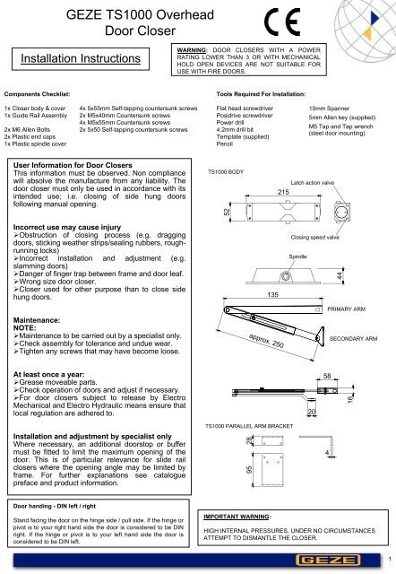
GEZE TS1000 OverheadDoor CloserInstallation <strong>Instruction</strong>sWARNING: DOOR CLOSERS WITH A POWERRATING LOWER THAN 3 OR WITH MECHANICALHOLD OPEN DEVICES ARE NOT SUITABLE FORUSE WITH FIRE DOORS.Components Checklist:Tools Required For Installation:1x Closer body & cover1x Guide Rail Assembly2x M6 Allen Bolts2x Plastic end caps1x Plastic spindle cover4x 5x55mm Self-tapping countersunk screws2x M5x40mm Countersunk screws4x M5x55mm Countersunk screws2x 5x50 Self-tapping countersunk screwsFlat head screwdriverPosidrive screwdriverPower drill4.2mm drill bitTemplate (supplied)Pencil10mm Spanner5mm Allen key (supplied)M5 Tap and Tap wrench(steel door mounting)User Information for Door ClosersThis information must be observed. Non compliancewill absolve the manufacture from any liability. Thedoor closer must only be used in accordance with itsintended use; i.e. closing of side hung doorsfollowing manual opening.Incorrect use may cause injury‣Obstruction of closing process (e.g. draggingdoors, sticking weather strips/sealing rubbers, roughrunninglocks)‣Incorrect installation and adjustment (e.g.slamming doors)‣Danger of finger trap between frame and door leaf.‣Wrong size door closer.‣Closer used for other purpose than to close sidehung doors.TS1000 BODY52135Latch action valve215Closing speed valveSpindle442 1Maintenance:NOTE:‣Maintenance to be carried out by a specialist only.‣Check assembly for tolerance and undue wear.‣Tighten any screws that may have become loose.approx. 250PRIMARY ARMSECONDARY ARMAt least once a year:‣Grease moveable parts.‣Check operation of doors and adjust if necessary.‣For door closers subject to release by ElectroMechanical and Electro Hydraulic means ensure thatlocal regulation are adhered to.205816Installation and adjustment by specialist onlyWhere necessary, an additional doorstop or buffermust be fitted to limit the maximum opening of thedoor. This is of particular relevance for slide railclosers where the opening angle may be limited byframe. For further explanations see cataloguepreface and product information.TS1000 PARALLEL ARM BRACKET95 284Door handing - DIN left / rightStand facing the door on the hinge side / pull side. If the hinge orpivot is to your right hand side the door is considered to be DINright. If the hinge or pivot is to your left hand side the door isconsidered to be DIN left.IMPORTANT WARNING:HIGH INTERNAL PRESSURES, UNDER NO CIRCUMSTANCESATTEMPT TO DISMANTLE THE CLOSER.1
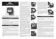
Fixing in figure 13137.5184 4545 18417.5313117.582 196196 82‣With the aid of the template mark out the fixing positions. Align thehinge point of the template with the centre line of the hinge on thedoor. (This applies to both left and right-hand doors.) There are twoholes to be drilled/tapped on the transom for the arm shoe and fourholes to be drilled/tapped on the door leaf for the closer body. If thetemplate is not used refer to fixing dimensions (see figure 1 and 2above.)80°Fig3‣Secure closer body with screws provided, making sure that thespindle is positioned towards the hinge side. (See figure 1 and 2above.)‣ Secure the arm to the spindle using M6 bolt supplied. Locate armat approx. 80° with respect to the door leaf, towards the hinge point.(See figure 3.) Fix the shoe to the transom using the screwsprovided and loosen 10mm locking bolt on arm. Prime the closerslightly by rotating the primary arm to approx. 90° with respect tothe door leaf and tighten the locking bolt. (See figure 4.)90°Fig4‣The latch action of the TS1000C can now be adjusted using theadjustment valve located on the side (see figure a) of the body of thecloser next to the closing speed adjustment valve. Clockwise willdecrease the latch action and anticlockwise will increase the latchaction. Do not overtighten.‣The closing speed can now be adjusted using the adjustment valvelocated on the side (see figure a) of the body of the closer.Clockwise will decrease the closing speed and anticlockwise willincrease the closing speed. Do not overtighten.Fig5‣Test installation by simulating persons using the entrance. Thedoor should close smoothly without slamming and present nopotential hazard to traffic.90°‣When commissioning is complete push on the, black plastic,spindle cover cap and clip on front cover.2
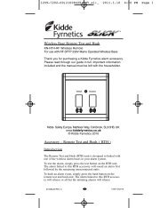
Fixing in figure 61821961968217.5313117.537.5 31184 4545 184‣With the aid of the template mark out the fixing positions. Align thehinge point of the template with the centre line of the hinge on thedoor. (This applies to both left and right-hand doors.) There are twoholes to be drilled/tapped on the door leaf for the arm shoe and fourholes to be drilled/tapped on the transom for the closer body. If thetemplate is not used refer to fixing dimensions (see figure 1 and 2above.)80°Fig3‣Secure closer body with screws provided, making sure that thespindle is positioned towards the hinge side. (See figure 1 and 2above.)‣Secure the arm to the spindle using M6 allen bolt supplied. Locatearm at approx. 80° with respect to the door leaf, towards the hingepoint. (See figure 3.) Fix the shoe to the door leaf using the screwsprovided and loosen 10mm locking bolt on arm. Prime the closerslightly by rotating the primary arm to approx. 90° with respect tothe door leaf and tighten the locking bolt. (See figure 4.)Fig4‣The latch action of the TS1000C can now be adjusted using theadjustment valve located on the side of the body of the closer next tothe closing speed adjustment valve. Clockwise will decrease thelatch action and anticlockwise will increase the latch action. Do notovertighten.90°‣The closing speed can now be adjusted using the adjustment valvelocated on the side of the body of the closer. Clockwise will decreasethe closing speed and anticlockwise will increase the closing speed.Do not overtighten.Fig5‣Test installation by simulating persons using the entrance. Thedoor should close smoothly without slamming and present nopotential hazard to traffic.90°‣When commissioning is complete push on the, black plastic,spindle cover cap and clip on the front cover.3