Untitled
Untitled
Untitled
- No tags were found...

You also want an ePaper? Increase the reach of your titles
YUMPU automatically turns print PDFs into web optimized ePapers that Google loves.
STEP MOTORTable of contenspag.Hybrid stepper motor > > > Codifications and test 31,8° Size 22 mm High torque 4-51,8° Size 35-39 mm High torque 6 - 80,9° Size 42 mm High torque 9 - 111,8° Size 42 mm High torque 12 - 141,8° Size 57 mm Standard 15 - 180,9° Size 57 mm High torque 19 - 211,8° Size 57 mm High torque 22 - 251,8° Size 86 mm High torque 26 - 291,8° Size 110 mm High torque 30 - 32Theory > > >Stepper motor basic 33 - 39DELTA PRECISION MOTORS
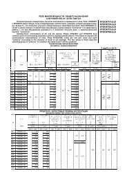
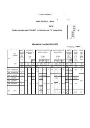
STEP MOTORCodification Number42 Size in mm.S Motor type: S= stepper / SH= stepper high torque33 Motor lenght in mm.XXXX Winding codeA Shaft configuration: A= 1 shaft / B= 2 shaftM M= 400 step/revXXXX Exec: Number Special configurationSHAFT CONFIGURATIONAll motors can be supplied with single or double ended shaft(standard or customized design).ROTATIONStepper motors can run clockwise or counterclockwise,depending on the commutation.BEARINGHybrid stepper motors fitted with ball bearings.RECOM AMBIENT TEMPERATURE RANGE-20° C to +40° C.HOLDING TORQUEHolding torque is measured with two phases suppliedat the rated current.INSULATION CLASSClass B.Test and controlsPRODUCTION FINAL TESTDelta Precision Motors ltd. I02 Tc0 Tw211 cs 64 165j/F4 1l-9 fesltd. Tf0 -0.3472 Tw5.9(manufacrising)]TJr which14(edevor)-1.9(r)-3augn• Insulation resistance: 500VDC, 100Mohm• Dielectric strength: 620VAC, 1 sec, 2mA• Resistance/phase• Inductance/phase• Holding torque• Detent torque• Direction testingRUNNING TEST• Max. running frequency at no load• Smooth running• Noise and vibrationAPPEARANCE TESTING• Output shaft• Lead wires•Mounting dimension (flange - screw - D-cut - etc)QUALITY CONTROL ADDITIONAL TEST•Frequency vs torque curve• No load temperature risingThe technical specifications mentioned are typicalDELTA PRECISION MOTORS 3
Step Motor28SH51HIGH TORQUE HYBRID - 200 STEPDimensions in mm.MODEL 28SH51-0956A 28SH51-0674A1 STEP ANGLE 1,8° 1,8°2 STEP ANGLE ACCURACY(FULL STEP, NO LOAD) % ±5% ±5%3 RATED VOLTAGE V 4,4 6,24 CURRENT/PHASE A 0,95 0,675 RESISTANCE/PHASE Ω 4,6 9,26 INDUCTANCE/PHASE MH 1,4 5,77 HOLDINGDELTA PRECISION MOTORS 5
35-39SH20-26HYBRID - 200 STEPStep MotorDimensions in mm.MODEL 35SH26-0306A 35SH26-0804A 39SH20-0404A 39SH20-0506A1 STEP ANGLE 1,8° 1,8° 1,8° 1,8°2 STEP ANGLE ACCURACY(FULL STEP, NO LOAD) % ±5% ±5% ±5% ±5%3 RATED VOLTAGE V 11,25 3,84 2,64 6,54 CURRENT/PHASE A 0,25 0,8 0,4 0,55 RESISTANCE/PHASE Ω 45 4,8 6,6 136 INDUCTANCE/PHASE MH 13 3 7,5 7,57 DETENT TORQUE MNM 6 6 5 58 HOLDING TORQUE NCM 5 5 6,5 89 ROTOR INERTIA G-CM 2 10 10 11 1110 WEIGHT KG 0,15 0,15 0,12 0,1211 NUMBER OF LEADS N°. 6 4 4 635-39S..-.A single shaft • 35-39S..-.B double shaftSpecificationsSpeed vs. Torque CharacteristicsCharacteristicsRESISTANCE ACCURACY± 10%INDUCTANCE ACCURACY± 20%TEMPERATURE RISE80° C max. (rated current, 2 phase on)AMBIENT TEMPERATURE-10° C - + 50° CINSULATION RESISTANCE100 M Ω min., 500 VDCDIELECTRIC STRENGTH500 VAC for one minuteSHAFT RADIAL PLAY0,06 max. (450 g-load)SHAFT AXIAL PLAY0,08 max. (450 g-load)35SH26-0306A35SH26-0804A39SH20-0404A39SH20-0506AAVAILABLE OPTIONSMotor modifications:custom winding, special bearing, special tap.Shaft modifications:flat, pinion, keyway, length.Leadwire modifications:wire type, wire color, wire length, connectorinstallation.6 DELTA PRECISION MOTORS
Step Motor39SH34HYBRID - 200 STEPDimensions in mm.MODEL 39SH34-0654A 39SH34-0404A 39SH34-0604A 39SH34-0306A1 STEP ANGLE 1,8° 1,8° 1,8° 1,8°2 STEP ANGLE ACCURACY(FULL STEP, NO LOAD) % ±5% ±5% ±5% ±5%3 RATED VOLTAGE V 4,55 12 9 124 CURRENT/PHASE A 0,65 0,4 0,6 0,35 RESISTANCE/PHASE Ω 7 30 15 406 INDUCTANCE/PHASE MH 9,3 32 16 207 DETENT TORQUE MNM 12 12 12 128 HOLDING TORQUE NCM 18 21 21 139 ROTOR INERTIA G-CM 2 20 20 20 2010 WEIGHT KG 0,18 0,18 0,18 0,1811 NUMBER OF LEADS N°. 4 4 4 639S..-.A single shaft • 39S..-.B double shaftSpecificationsSpeed vs. Torque Characteristics39SH34-0654A39SH34-0404ACharacteristicsRESISTANCE ACCURACY± 10%INDUCTANCE ACCURACY± 20%TEMPERATURE RISE80° C max. (rated current, 2 phase on)AMBIENT TEMPERATURE-10° C - + 50° CINSULATION RESISTANCE100 M Ω min., 500 VDCDIELECTRIC STRENGTH500 VAC for one minuteSHAFT RADIAL PLAY0,06 max. (450 g-load)SHAFT AXIAL PLAY0,08 max. (450 g-load)39SH34-0604A39SH34-0306AAVAILABLE OPTIONSMotor modifications:custom winding, special bearing, special tap.Shaft modifications:flat, pinion, keyway, length.Leadwire modifications:wire type, wire color, wire length, connectorinstallation.DELTA PRECISION MOTORS 7
39SH38-44HYBRID - 200 STEPStep MotorDimensions in mm.MODEL 39SH38-0504A 39SH38-0806A 39SH44-0304A1 STEP ANGLE 1,8° 1,8° 1,8°2 STEP ANGLE ACCURACY(FULL STEP, NO LOAD) % ±5% ±5% ±5%3 RATED VOLTAGE V 12 6 124 CURRENT/PHASE A 0,5 0,8 0,35 RESISTANCE/PHASE Ω 24 7,5 406 INDUCTANCE/PHASE MH 45 6 1007 DETENT TORQUE MNM 18 18 258 HOLDING TORQUE NCM 29 20 289 ROTOR INERTIA G-CM 2 24 24 4010 WEIGHT KG 0,20 0,20 0,2511 NUMBER OF LEADS N°. 4 6 439S..-.A single shaft • 39S..-.B double shaftSpecificationsSpeed vs. Torque CharacteristicsCharacteristicsRESISTANCE ACCURACY± 10%INDUCTANCE ACCURACY± 20%TEMPERATURE RISE80° C max. (rated current, 2 phase on)AMBIENT TEMPERATURE-10° C - + 50° CINSULATION RESISTANCE100 M Ω min., 500 VDCDIELECTRIC STRENGTH500 VAC for one minuteSHAFT RADIAL PLAY0,06 max. (450 g-load)SHAFT AXIAL PLAY0,08 max. (450 g-load)39SH38-0504A39SH38-0806A39SH44-0304AAVAILABLE OPTIONSMotor modifications:custom winding, special bearing, special tap.Shaft modifications:flat, pinion, keyway, length.Leadwire modifications:wire type, wire color, wire length, connectorinstallation.8 DELTA PRECISION MOTORS
Step Motor42SH33HIGH TORQUE HYBRID - 400 STEPDimensions in mm.MODEL 42SH33-1AM 42SH33-2AM 42SH33-3AM 42SH33-4AM1 STEP ANGLE 0,9° 0,9° 0,9° 0,9°2 STEP ANGLE ACCURACY(FULL STEP, NO LOAD) % ±5% ±5% ±5% ±5%3 RATED VOLTAGE V 4 6 12 2,84 CURRENT/PHASE A 0,95 0,6 0,31 1,335 RESISTANCE/PHASE Ω 4,2 10 38,5 2,16 INDUCTANCE/PHASE MH 2,5 6,1 21 2,57 DETENT TORQUE MNM 20 20 20 208 HOLDING TORQUE NCM 15,8 15,8 15,8 229 ROTOR INERTIA G-CM 2 35 35 35 3510 WEIGHT KG 0,22 0,22 0,22 0,2211 NUMBER OF LEADS N°. 6 6 6 442SH..-.A single shaft • 42SH..-.B double shaftSpecificationsSpeed vs. Torque Characteristics42SH33-1AM42SH33-2AMCharacteristicsRESISTANCE ACCURACY± 10%INDUCTANCE ACCURACY± 20%TEMPERATURE RISE80° C max. (rated current, 2 phase on)AMBIENT TEMPERATURE-10° C - + 50° CINSULATION RESISTANCE100 M Ω min., 500 VDCDIELECTRIC STRENGTH500 VAC for one minuteSHAFT RADIAL PLAY0,06 max. (450 g-load)SHAFT AXIAL PLAY0,08 max. (450 g-load)42SH33-3AM42SH33-4AMAVAILABLE OPTIONSMotor modifications:custom winding, special bearing, special tap.Shaft modifications:flat, pinion, keyway, length.Leadwire modifications:wire type, wire color, wire length, connectorinstallation.DELTA PRECISION MOTORS 9
42SH38HIGH TORQUE HYBRID - 400 STEPStep MotorDimensions in mm.MODEL 42SH38-1AM 42SH38-2AM 42SH38-3AM 42SH38-4AM1 STEP ANGLE 0,9° 0,9° 0,9° 0,9°2 STEP ANGLE ACCURACY(FULL STEP, NO LOAD) % ±5% ±5% ±5% ±5%3 RATED VOLTAGE V 4 6 12 2,84 CURRENT/PHASE A 1,2 0,8 0,4 1,685 RESISTANCE/PHASE Ω 3,3 7,5 30 1,656 INDUCTANCE/PHASE MH 3,2 6,7 30 3,27 DETENT TORQUE MNM 22 22 22 228 HOLDING TORQUE NCM 25,9 25,9 25,9 369 ROTOR INERTIA G-CM 2 54 54 54 5410 WEIGHT KG 0,28 0,28 0,28 0,2811 NUMBER OF LEADS N°. 6 6 6 442SH..-.A single shaft • 42SH..-.B double shaftSpecificationsSpeed vs. Torque CharacteristicsCharacteristicsRESISTANCE ACCURACY± 10%INDUCTANCE ACCURACY± 20%TEMPERATURE RISE80° C max. (rated current, 2 phase on)AMBIENT TEMPERATURE-10° C - + 50° CINSULATION RESISTANCE100 M Ω min., 500 VDCDIELECTRIC STRENGTH500 VAC for one minuteSHAFT RADIAL PLAY0,06 max. (450 g-load)SHAFT AXIAL PLAY0,08 max. (450 g-load)42SH38-1AM42SH38-2AM42SH38-3AM42SH38-4AMAVAILABLE OPTIONSMotor modifications:custom winding, special bearing, special tap.Shaft modifications:flat, pinion, keyway, length.Leadwire modifications:wire type, wire color, wire length, connectorinstallation.10 DELTA PRECISION MOTORS
Step Motor42SH47HIGH TORQUE HYBRID - 400 STEPDimensions in mm.MODEL 42SH47-1AM 42SH47-2AM 42SH47-3AM 42SH47-4AM1 STEP ANGLE 0,9° 0,9° 0,9° 0,9°2 STEP ANGLE ACCURACY(FULL STEP, NO LOAD) % ±5% ±5% ±5% ±5%3 RATED VOLTAGE V 4 6 12 2,84 CURRENT/PHASE A 1,2 0,8 0,4 1,685 RESISTANCE/PHASE Ω 3,3 7,5 30 1,656 INDUCTANCE/PHASE MH 2,8 6,3 25 2,87 DETENT TORQUE MNM 25 25 25 258 HOLDING TORQUE NCM 31,7 31,7 31,7 449 ROTOR INERTIA G-CM 2 68 68 68 6810 WEIGHT KG 0,35 0,35 0,35 0,3511 NUMBER OF LEADS N°. 6 6 6 442SH..-.A single shaft • 42SH..-.B double shaftSpecificationsSpeed vs. Torque Characteristics42SH47-1AM42SH47-2AMCharacteristicsRESISTANCE ACCURACY± 10%INDUCTANCE ACCURACY± 20%TEMPERATURE RISE80° C max. (rated current, 2 phase on)AMBIENT TEMPERATURE-10° C - + 50° CINSULATION RESISTANCE100 M Ω min., 500 VDCDIELECTRIC STRENGTH500 VAC for one minuteSHAFT RADIAL PLAY0,06 max. (450 g-load)SHAFT AXIAL PLAY0,08 max. (450 g-load)42SH47-3AM42SH47-4AMAVAILABLE OPTIONSMotor modifications:custom winding, special bearing, special tap.Shaft modifications:flat, pinion, keyway, length.Leadwire modifications:wire type, wire color, wire length, connectorinstallation.DELTA PRECISION MOTORS 11
42SH33HIGH TORQUE HYBRID - 200 STEPStep MotorDimensions in mm.MODEL 42SH33-1A 42SH33-2A 42SH33-3A 42SH33-4A1 STEP ANGLE 1,8° 1,8° 1,8° 1,8°2 STEP ANGLE ACCURACY(FULL STEP, NO LOAD) % ±5% ±5% ±5% ±5%3 RATED VOLTAGE V 4 9,6 12 2,84 CURRENT/PHASE A 0,95 0,4 0,31 1,335 RESISTANCE/PHASE Ω 4,2 24 38,5 2,16 INDUCTANCE/PHASE MH 2,5 15 21 2,57 DETENT TORQUE MNM 20 20 20 208 HOLDING TORQUE NCM 15,8 15,8 15,8 229 ROTOR INERTIA G-CM 2 35 35 35 3510 WEIGHT KG 0,22 0,22 0,22 0,2211 NUMBER OF LEADS N°. 6 6 6 442SH..-.A single shaft • 42SH..-.B double shaftSpecificationsSpeed vs. Torque CharacteristicsCharacteristicsRESISTANCE ACCURACY± 10%INDUCTANCE ACCURACY± 20%TEMPERATURE RISE80° C max. (rated current, 2 phase on)AMBIENT TEMPERATURE-10° C - + 50° CINSULATION RESISTANCE100 M Ω min., 500 VDCDIELECTRIC STRENGTH500 VAC for one minuteSHAFT RADIAL PLAY0,06 max. (450 g-load)SHAFT AXIAL PLAY0,08 max. (450 g-load)42SH33-1A42SH33-2A42SH33-3A42SH33-4AAVAILABLE OPTIONSMotor modifications:custom winding, special bearing, special tap.Shaft modifications:flat, pinion, keyway, length.Leadwire modifications:wire type, wire color, wire length, connectorinstallation.12 DELTA PRECISION MOTORS
Step Motor42SH38HIGH TORQUE HYBRID - 200 STEPDimensions in mm.MODEL 42SH38-1A 42SH38-2A 42SH38-3A 42SH38-4A1 STEP ANGLE 1,8° 1,8° 1,8° 1,8°2 STEP ANGLE ACCURACY(FULL STEP, NO LOAD) % ±5% ±5% ±5% ±5%3 RATED VOLTAGE V 4 6 12 2,84 CURRENT/PHASE A 1,2 0,8 0,4 1,685 RESISTANCE/PHASE Ω 3,3 7,5 30 1,656 INDUCTANCE/PHASE MH 3,2 6,7 30 3,27 DETENT TORQUE MNM 22 22 22 228 HOLDING TORQUE NCM 25,9 25,9 25,9 369 ROTOR INERTIA G-CM 2 54 54 54 5410 WEIGHT KG 0,28 0,28 0,28 0,2811 NUMBER OF LEADS N°. 6 6 6 442SH..-.A single shaft • 42SH..-.B double shaftSpecificationsSpeed vs. Torque Characteristics42SH38-1A42SH38-2ACharacteristicsRESISTANCE ACCURACY± 10%INDUCTANCE ACCURACY± 20%TEMPERATURE RISE80° C max. (rated current, 2 phase on)AMBIENT TEMPERATURE-10° C - + 50° CINSULATION RESISTANCE100 M Ω min., 500 VDCDIELECTRIC STRENGTH500 VAC for one minuteSHAFT RADIAL PLAY0,06 max. (450 g-load)SHAFT AXIAL PLAY0,08 max. (450 g-load)42SH38-3A42SH38-4AAVAILABLE OPTIONSMotor modifications:custom winding, special bearing, special tap.Shaft modifications:flat, pinion, keyway, length.Leadwire modifications:wire type, wire color, wire length, connectorinstallation.DELTA PRECISION MOTORS 13
42SH47HIGH TORQUE HYBRID - 200 STEPStep MotorDimensions in mm.MODEL 42SH47-1A 42SH47-2A 42SH47-3A 42SH47-4A1 STEP ANGLE 1,8° 1,8° 1,8° 1,8°2 STEP ANGLE ACCURACY(FULL STEP, NO LOAD) % ±5% ±5% ±5% ±5%3 RATED VOLTAGE V 4 6 12 2,84 CURRENT/PHASE A 1,2 0,8 0,4 1,685 RESISTANCE/PHASE Ω 3,3 7,5 30 1,656 INDUCTANCE/PHASE MH 2,8 6,3 25 2,87 DETENT TORQUE MNM 25 25 25 258 HOLDING TORQUE NCM 36 31,7 31,7 449 ROTOR INERTIA G-CM 2 68 68 68 6810 WEIGHT KG 0,35 0,35 0,35 0,3511 NUMBER OF LEADS N°. 6 6 6 442SH..-.A single shaft • 42SH..-.B double shaftSpecificationsSpeed vs. Torque CharacteristicsCharacteristicsRESISTANCE ACCURACY± 10%INDUCTANCE ACCURACY± 20%TEMPERATURE RISE80° C max. (rated current, 2 phase on)AMBIENT TEMPERATURE-10° C - + 50° CINSULATION RESISTANCE100 M Ω min., 500 VDCDIELECTRIC STRENGTH500 VAC for one minuteSHAFT RADIAL PLAY0,06 max. (450 g-load)SHAFT AXIAL PLAY0,08 max. (450 g-load)42SH47-1A42SH47-2A42SH47-3A42SH47-4AAVAILABLE OPTIONSMotor modifications:custom winding, special bearing, special tap.Shaft modifications:flat, pinion, keyway, length.Leadwire modifications:wire type, wire color, wire length, connectorinstallation.14 DELTA PRECISION MOTORS
Step Motor57S41HYBRID - 200 STEPDimensions in mm.MODEL 57S41-1A 57S41-2A 57S41-4A1 STEP ANGLE 1,8° 1,8° 1,8°2 STEP ANGLE ACCURACY(FULL STEP, NO LOAD) % ±5% ±5% ±5%3 RATED VOLTAGE V 4 12 2,84 CURRENT/PHASE A 1,1 0,4 1,565 RESISTANCE/PHASE Ω 3,6 30 1,86 INDUCTANCE/PHASE MH 3,6 30 3,67 DETENT TORQUE MNM 18 18 188 HOLDING TORQUE NCM 28,8 28,8 409 ROTOR INERTIA G-CM 2 57 57 5710 WEIGHT KG 0,54 0,54 0,5411 NUMBER OF LEADS N°. 6 6 457S..-.A single shaft • 57S..-.B double shaftSpecificationsSpeed vs. Torque Characteristics57S41-1A57S41-2ACharacteristicsRESISTANCE ACCURACY± 10%INDUCTANCE ACCURACY± 20%TEMPERATURE RISE80° C max. (rated current, 2 phase on)AMBIENT TEMPERATURE-10° C - + 50° CINSULATION RESISTANCE100 M Ω min., 500 VDCDIELECTRIC STRENGTH500 VAC for one minuteSHAFT RADIAL PLAY0,06 max. (450 g-load)SHAFT AXIAL PLAY0,08 max. (450 g-load)57S41-4AAVAILABLE OPTIONSMotor modifications:custom winding, special bearing, special tap.Shaft modifications:flat, pinion, keyway, length.Leadwire modifications:wire type, wire color, wire length, connectorinstallation.DELTA PRECISION MOTORS 15
57S51HYBRID - 200 STEPStep MotorDimensions in mm.MODEL 57S51-1A 57S51-2A 57S51-4A1 STEP ANGLE 1,8° 1,8° 1,8°2 STEP ANGLE ACCURACY(FULL STEP, NO LOAD) % ±5% ±5% ±5%3 RATED VOLTAGE V 6 12 1,84 CURRENT/PHASE A 0,85 0,42 2,85 RESISTANCE/PHASE Ω 7,1 29 0,656 INDUCTANCE/PHASE MH 9 36 1,67 DETENT TORQUE MNM 35 35 358 HOLDING TORQUE NCM 49,7 49,7 699 ROTOR INERTIA G-CM 2 110 110 11010 WEIGHT KG 0,60 0,60 0,6011 NUMBER OF LEADS N°. 6 6 457S..-.A single shaft • 57S..-.B double shaftSpecificationsSpeed vs. Torque CharacteristicsCharacteristicsRESISTANCE ACCURACY± 10%INDUCTANCE ACCURACY± 20%TEMPERATURE RISE80° C max. (rated current, 2 phase on)AMBIENT TEMPERATURE-10° C - + 50° CINSULATION RESISTANCE100 M Ω min., 500 VDCDIELECTRIC STRENGTH500 VAC for one minuteSHAFT RADIAL PLAY0,06 max. (450 g-load)SHAFT AXIAL PLAY0,08 max. (450 g-load)57S51-1A57S51-2A57S51-4AAVAILABLE OPTIONSMotor modifications:custom winding, special bearing, special tap.Shaft modifications:flat, pinion, keyway, length.Leadwire modifications:wire type, wire color, wire length, connectorinstallation.16 DELTA PRECISION MOTORS
Step Motor57S56HYBRID - 200 STEPDimensions in mm.MODEL 57S56-1A 57S56-2A 57S56-4A1 STEP ANGLE 1,8° 1,8° 1,8°2 STEP ANGLE ACCURACY(FULL STEP, NO LOAD) % ±5% ±5% ±5%3 RATED VOLTAGE V 6 12 2,84 CURRENT/PHASE A 1,2 0,6 2,555 RESISTANCE/PHASE Ω 5 20 1,16 INDUCTANCE/PHASE MH 8 32 3,67 DETENT TORQUE MNM 42 42 428 HOLDING TORQUE NCM 60,5 60,5 849 ROTOR INERTIA G-CM 2 135 135 13510 WEIGHT KG 0,65 0,65 0,6511 NUMBER OF LEADS N°. 6 6 457S..-.A single shaft • 57S..-.B double shaftSpecificationsSpeed vs. Torque Characteristics57S56-1A57S56-2ACharacteristicsRESISTANCE ACCURACY± 10%INDUCTANCE ACCURACY± 20%TEMPERATURE RISE80° C max. (rated current, 2 phase on)AMBIENT TEMPERATURE-10° C - + 50° CINSULATION RESISTANCE100 M Ω min., 500 VDCDIELECTRIC STRENGTH500 VAC for one minuteSHAFT RADIAL PLAY0,06 max. (450 g-load)SHAFT AXIAL PLAY0,08 max. (450 g-load)57S56-4AAVAILABLE OPTIONSMotor modifications:custom winding, special bearing, special tap.Shaft modifications:flat, pinion, keyway, length.Leadwire modifications:wire type, wire color, wire length, connectorinstallation.DELTA PRECISION MOTORS 17
57S76HYBRID - 200 STEPStep MotorDimensions in mm.MODEL 57S76-1A 57S76-2A 57S76-4A1 STEP ANGLE 1,8° 1,8° 1,8°2 STEP ANGLE ACCURACY(FULL STEP, NO LOAD) % ±5% ±5% ±5%3 RATED VOLTAGE V 5,4 12 2,74 CURRENT/PHASE A 1,5 0,68 3,35 RESISTANCE/PHASE Ω 3,6 17,7 0,856 INDUCTANCE/PHASE MH 6 30 37 DETENT TORQUE MNM 72 72 728 HOLDING TORQUE NCM 90 90 1259 ROTOR INERTIA G-CM 2 200 200 20010 WEIGHT KG 0,95 0,95 0,9511 NUMBER OF LEADS N°. 6 6 457S..-.A single shaft • 57S..-.B double shaftSpecificationsSpeed vs. Torque CharacteristicsCharacteristicsRESISTANCE ACCURACY± 10%INDUCTANCE ACCURACY± 20%TEMPERATURE RISE80° C max. (rated current, 2 phase on)AMBIENT TEMPERATURE-10° C - + 50° CINSULATION RESISTANCE100 M Ω min., 500 VDCDIELECTRIC STRENGTH500 VAC for one minuteSHAFT RADIAL PLAY0,06 max. (450 g-load)SHAFT AXIAL PLAY0,08 max. (450 g-load)57S76-1A57S76-2A57S76-4AAVAILABLE OPTIONSMotor modifications:custom winding, special bearing, special tap.Shaft modifications:flat, pinion, keyway, length.Leadwire modifications:wire type, wire color, wire length, connectorinstallation.18 DELTA PRECISION MOTORS
Step Motor57SH39HIGH TORQUE HYBRID - 400 STEPDimensions in mm.MODEL 57SH39-1AM 57SH39-2AM 57SH39-3AM 57SH39-4AM1 STEP ANGLE 0,9° 0,9° 0,9° 0,9°2 STEP ANGLE ACCURACY(FULL STEP, NO LOAD) % ±5% ±5% ±5% ±5%3 RATED VOLTAGE V 5,7 2,8 1,9 24 CURRENT/PHASE A 1 2 3 2,85 RESISTANCE/PHASE Ω 5,7 1,4 0,63 0,76 INDUCTANCE/PHASE MH 5,4 1,4 0,6 1,47 DETENT TORQUE MNM 21 21 21 218 HOLDING TORQUE NCM 39 39 39 559 ROTOR INERTIA G-CM 2 120 120 120 12010 WEIGHT KG 0,45 0,45 0,45 0,4511 NUMBER OF LEADS N°. 6 6 6 457SH..-.A single shaft • 57SH..-.B double shaftSpecificationsSpeed vs. Torque Characteristics57SH39-1AM57SH39-2AMCharacteristicsRESISTANCE ACCURACY± 10%INDUCTANCE ACCURACY± 20%TEMPERATURE RISE80° C max. (rated current, 2 phase on)AMBIENT TEMPERATURE-10° C - + 50° CINSULATION RESISTANCE100 M Ω min., 500 VDCDIELECTRIC STRENGTH500 VAC for one minuteSHAFT RADIAL PLAY0,06 max. (450 g-load)SHAFT AXIAL PLAY0,08 max. (450 g-load)57SH39-3AM57SH39-4AMAVAILABLE OPTIONSMotor modifications:custom winding, special bearing, special tap.Shaft modifications:flat, pinion, keyway, length.Leadwire modifications:wire type, wire color, wire length, connectorinstallation.DELTA PRECISION MOTORS 19
57SH56HIGH TORQUE HYBRID - 400 STEPStep MotorDimensions in mm.MODEL 57SH56-1AM 57SH56-2AM 57SH56-3AM 57SH56-4AM1 STEP ANGLE 0,9° 0,9° 0,9° 0,9°2 STEP ANGLE ACCURACY(FULL STEP, NO LOAD) % ±5% ±5% ±5% ±5%3 RATED VOLTAGE V 7,4 3,6 2,3 2,54 CURRENT/PHASE A 1 2 3 2,85 RESISTANCE/PHASE Ω 7,4 1,8 0,75 0,96 INDUCTANCE/PHASE MH 10 2,5 1,1 2,57 DETENT TORQUE MNM 40 40 40 408 HOLDING TORQUE NCM 90 90 90 1269 ROTOR INERTIA G-CM 2 300 300 300 30010 WEIGHT KG 0,7 0,7 0,7 0,711 NUMBER OF LEADS N°. 6 6 6 457SH..-.A single shaft • 57SH..-.B double shaftSpecificationsSpeed vs. Torque CharacteristicsCharacteristicsRESISTANCE ACCURACY± 10%INDUCTANCE ACCURACY± 20%TEMPERATURE RISE80° C max. (rated current, 2 phase on)AMBIENT TEMPERATURE-10° C - + 50° CINSULATION RESISTANCE100 M Ω min., 500 VDCDIELECTRIC STRENGTH500 VAC for one minuteSHAFT RADIAL PLAY0,06 max. (450 g-load)SHAFT AXIAL PLAY0,08 max. (450 g-load)57SH56-1AM57SH56-2AM57SH56-3AM57SH56-4AMAVAILABLE OPTIONSMotor modifications:custom winding, special bearing, special tap.Shaft modifications:flat, pinion, keyway, length.Leadwire modifications:wire type, wire color, wire length, connectorinstallation.20 DELTA PRECISION MOTORS
Step Motor57SH76HIGH TORQUE HYBRID - 400 STEPDimensions in mm.MODEL 57SH76-1AM 57SH76-2AM 57SH76-3AM 57SH76-4AM1 STEP ANGLE 0,9° 0,9° 0,9° 0,9°2 STEP ANGLE ACCURACY(FULL STEP, NO LOAD) % ±5% ±5% ±5% ±5%3 RATED VOLTAGE V 8,6 4,5 3 3,24 CURRENT/PHASE A 1 2 3 2,85 RESISTANCE/PHASE Ω 8,6 2,25 1 1,136 INDUCTANCE/PHASE MH 14 3,6 1,6 3,67 DETENT TORQUE MNM 68 68 68 688 HOLDING TORQUE NCM 135 135 135 1899 ROTOR INERTIA G-CM 2 480 480 480 48010 WEIGHT KG 1 1 1 111 NUMBER OF LEADS N°. 6 6 6 457SH..-.A single shaft • 57SH..-.B double shaftSpecificationsSpeed vs. Torque Characteristics57SH76-1AM57SH76-2AMCharacteristicsRESISTANCE ACCURACY± 10%INDUCTANCE ACCURACY± 20%TEMPERATURE RISE80° C max. (rated current, 2 phase on)AMBIENT TEMPERATURE-10° C - + 50° CINSULATION RESISTANCE100 M Ω min., 500 VDCDIELECTRIC STRENGTH500 VAC for one minuteSHAFT RADIAL PLAY0,06 max. (450 g-load)SHAFT AXIAL PLAY0,08 max. (450 g-load)57SH76-3AM57SH76-4AMAVAILABLE OPTIONSMotor modifications:custom winding, special bearing, special tap.Shaft modifications:flat, pinion, keyway, length.Leadwire modifications:wire type, wire color, wire length, connectorinstallation.DELTA PRECISION MOTORS 21
57SH41HIGH TORQUE HYBRID - 200 STEPStep MotorDimensions in mm.MODEL 57SH41-1A 57SH41-2A 57SH41-3A 57SH41-4A1 STEP ANGLE 1,8° 1,8° 1,8° 1,8°2 STEP ANGLE ACCURACY(FULL STEP, NO LOAD) % ±5% ±5% ±5% ±5%3 RATED VOLTAGE V 5,7 2,8 1,9 24 CURRENT/PHASE A 1 2 3 2,85 RESISTANCE/PHASE Ω 5,7 1,4 0,63 0,76 INDUCTANCE/PHASE MH 5,4 1,4 0,6 1,47 DETENT TORQUE MNM 18 18 18 188 HOLDING TORQUE NCM 39 39 39 559 ROTOR INERTIA G-CM 2 120 120 120 12010 WEIGHT KG 0,45 0,45 0,45 0,4511 NUMBER OF LEADS N°. 6 6 6 457SH..-.A single shaft • 57SH..-.B double shaftSpecificationsSpeed vs. Torque CharacteristicsCharacteristicsRESISTANCE ACCURACY± 10%INDUCTANCE ACCURACY± 20%TEMPERATURE RISE80° C max. (rated current, 2 phase on)AMBIENT TEMPERATURE-10° C - + 50° CINSULATION RESISTANCE100 M Ω min., 500 VDCDIELECTRIC STRENGTH500 VAC for one minuteSHAFT RADIAL PLAY0,06 max. (450 g-load)SHAFT AXIAL PLAY0,08 max. (450 g-load)57SH41-1A57SH41-2A57SH41-3A57SH41-4AAVAILABLE OPTIONSMotor modifications:custom winding, special bearing, special tap.Shaft modifications:flat, pinion, keyway, length.Leadwire modifications:wire type, wire color, wire length, connectorinstallation.22 DELTA PRECISION MOTORS
Step Motor57SH51HIGH TORQUE HYBRID - 200 STEPDimensions in mm.MODEL 57SH51-1A 57SH51-2A 57SH51-3A 57SH51-4A1 STEP ANGLE 1,8° 1,8° 1,8° 1,8°2 STEP ANGLE ACCURACY(FULL STEP, NO LOAD) % ±5% ±5% ±5% ±5%3 RATED VOLTAGE V 6,6 3,3 2,2 2,34 CURRENT/PHASE A 1 2 3 2,85 RESISTANCE/PHASE Ω 6,6 1,65 0,74 0,836 INDUCTANCE/PHASE MH 8,2 2,2 0,9 2,27 DETENT TORQUE MNM 35 35 35 358 HOLDING TORQUE NCM 72 72 72 1019 ROTOR INERTIA G-CM 2 275 275 275 27510 WEIGHT KG 0,65 0,65 0,65 0,6511 NUMBER OF LEADS N°. 6 6 6 457SH..-.A single shaft • 57SH..-.B double shaftSpecificationsSpeed vs. Torque Characteristics57SH51-1A57SH51-2ACharacteristicsRESISTANCE ACCURACY± 10%INDUCTANCE ACCURACY± 20%TEMPERATURE RISE80° C max. (rated current, 2 phase on)AMBIENT TEMPERATURE-10° C - + 50° CINSULATION RESISTANCE100 M Ω min., 500 VDCDIELECTRIC STRENGTH500 VAC for one minuteSHAFT RADIAL PLAY0,06 max. (450 g-load)SHAFT AXIAL PLAY0,08 max. (450 g-load)57SH51-3A57SH51-4AAVAILABLE OPTIONSMotor modifications:custom winding, special bearing, special tap.Shaft modifications:flat, pinion, keyway, length.Leadwire modifications:wire type, wire color, wire length, connectorinstallation.DELTA PRECISION MOTORS 23
57SH56HIGH TORQUE HYBRID - 200 STEPStep MotorDimensions in mm.MODEL 57SH56-1A 57SH56-2A 57SH56-3A 57SH56-4A1 STEP ANGLE 1,8° 1,8° 1,8° 1,8°2 STEP ANGLE ACCURACY(FULL STEP, NO LOAD) % ±5% ±5% ±5% ±5%3 RATED VOLTAGE V 7,4 3,6 2,3 2,54 CURRENT/PHASE A 1 2 3 2,85 RESISTANCE/PHASE Ω 7,4 1,8 0,75 0,96 INDUCTANCE/PHASE MH 10 2,5 1,1 2,57 DETENT TORQUE MNM 42 42 42 428 HOLDING TORQUE NCM 90 90 90 1269 ROTOR INERTIA G-CM 2 300 300 300 30010 WEIGHT KG 0,7 0,7 0,7 0,711 NUMBER OF LEADS N°. 6 6 6 457SH..-.A single shaft • 57SH..-.B double shaftSpecificationsSpeed vs. Torque CharacteristicsCharacteristicsRESISTANCE ACCURACY± 10%INDUCTANCE ACCURACY± 20%TEMPERATURE RISE80° C max. (rated current, 2 phase on)AMBIENT TEMPERATURE-10° C - + 50° CINSULATION RESISTANCE100 M Ω min., 500 VDCDIELECTRIC STRENGTH500 VAC for one minuteSHAFT RADIAL PLAY0,06 max. (450 g-load)SHAFT AXIAL PLAY0,08 max. (450 g-load)57SH56-1A57SH56-2A57SH56-3A57SH56-4AAVAILABLE OPTIONSMotor modifications:custom winding, special bearing, special tap.Shaft modifications:flat, pinion, keyway, length.Leadwire modifications:wire type, wire color, wire length, connectorinstallation.24 DELTA PRECISION MOTORS
Step Motor57SH76HIGH TORQUE HYBRID - 200 STEPDimensions in mm.MODEL 57SH76-1A 57SH76-2A 57SH76-3A 57SH76-4A1 STEP ANGLE 1,8° 1,8° 1,8° 1,8°2 STEP ANGLE ACCURACY(FULL STEP, NO LOAD) % ±5% ±5% ±5% ±5%3 RATED VOLTAGE V 8,6 4,5 3 3,24 CURRENT/PHASE A 1 2 3 2,85 RESISTANCE/PHASE Ω 8,6 2,25 1 1,136 INDUCTANCE/PHASE MH 14 3,6 1,6 3,67 DETENT TORQUE MNM 72 72 72 728 HOLDING TORQUE NCM 135 135 135 1899 ROTOR INERTIA G-CM 2 480 480 480 48010 WEIGHT KG 1 1 1 111 NUMBER OF LEADS N°. 6 6 6 457SH..-.A single shaft • 57SH..-.B double shaftSpecificationsSpeed vs. Torque Characteristics57SH76-1A57SH76-2ACharacteristicsRESISTANCE ACCURACY± 10%INDUCTANCE ACCURACY± 20%TEMPERATURE RISE80° C max. (rated current, 2 phase on)AMBIENT TEMPERATURE-10° C - + 50° CINSULATION RESISTANCE100 M Ω min., 500 VDCDIELECTRIC STRENGTH500 VAC for one minuteSHAFT RADIAL PLAY0,06 max. (450 g-load)SHAFT AXIAL PLAY0,08 max. (450 g-load)57SH76-3A57SH76-4AAVAILABLE OPTIONSMotor modifications:custom winding, special bearing, special tap.Shaft modifications:flat, pinion, keyway, length.Leadwire modifications:wire type, wire color, wire length, connectorinstallation.DELTA PRECISION MOTORS 25
86SH65HIGH TORQUE HYBRID - 200 STEPStep MotorDimensions in mm.MODEL86SH65-3004A1 STEP ANGLE 1,8°2 STEP ANGLE ACCURACY(FULL STEP, NO LOAD) % ±5%3 PHASE 44 RATED VOLTAGE V 4,25 CURRENT/PHASE A 36 RESISTANCE/PHASE Ω 1,147 INDUCTANCE/PHASE MH 6,88 DETENT TORQUE MNM 809 HOLDING TORQUE NCM 34010 ROTOR INERTIA G-CM 2 100011 WEIGHT KG 1,712 NUMBER OF LEADS N°. 886SH..-.A single shaft • 86SH..-.B double shaftSpecificationsSpeed vs. Torque Characteristics86SH65-3004ACharacteristicsRESISTANCE ACCURACY± 10%INDUCTANCE ACCURACY± 20%TEMPERATURE RISE80° C max. (rated current, 2 phase on)AMBIENT TEMPERATURE-10° C - + 50° CINSULATION RESISTANCE100 M Ω min., 500 VDCDIELECTRIC STRENGTH500 VAC for one minuteSHAFT RADIAL PLAY0,06 max. (450 g-load)SHAFT AXIAL PLAY0,08 max. (450 g-load)AVAILABLE OPTIONSMotor modifications:custom winding, special bearing, special tap.Shaft modifications:flat, pinion, keyway, length.Leadwire modifications:wire type, wire color, wire length, connectorinstallation.26 DELTA PRECISION MOTORS
Step Motor86SH80HIGH TORQUE HYBRID - 200 STEPDimensions in mm.MODEL86SH80-5504A1 STEP ANGLE 1,8°2 STEP ANGLE ACCURACY(FULL STEP, NO LOAD) % ±5%3 PHASE 24 RATED VOLTAGE V 2,35 CURRENT/PHASE A 5,56 RESISTANCE/PHASE Ω 0,427 INDUCTANCE/PHASE MH 3,58 DETENT TORQUE MNM 1209 HOLDING TORQUE NCM 46010 ROTOR INERTIA G-CM 2 140011 WEIGHT KG 2,312 NUMBER OF LEADS N°. 486SH..-.A single shaft • 86SH..-.B double shaftSpecificationsSpeed vs. Torque Characteristics86SH80-5504ACharacteristicsRESISTANCE ACCURACY± 10%INDUCTANCE ACCURACY± 20%TEMPERATURE RISE80° C max. (rated current, 2 phase on)AMBIENT TEMPERATURE-10° C - + 50° CINSULATION RESISTANCE100 M Ω min., 500 VDCDIELECTRIC STRENGTH500 VAC for one minuteSHAFT RADIAL PLAY0,06 max. (450 g-load)SHAFT AXIAL PLAY0,08 max. (450 g-load)AVAILABLE OPTIONSMotor modifications:custom winding, special bearing, special tap.Shaft modifications:flat, pinion, keyway, length.Leadwire modifications:wire type, wire color, wire length, connectorinstallation.DELTA PRECISION MOTORS 27
86SH118HIGH TORQUE HYBRID - 200 STEPStep MotorDimensions in mm.MODEL86SH118-6004A1 STEP ANGLE 1,8°2 STEP ANGLE ACCURACY(FULL STEP, NO LOAD) % ±5%3 PHASE 24 RATED VOLTAGE V 2,75 CURRENT/PHASE A 66 RESISTANCE/PHASE Ω 0,457 INDUCTANCE/PHASE MH 5,18 DETENT TORQUE MNM 2409 HOLDING TORQUE NCM 87010 ROTOR INERTIA G-CM 2 270011 WEIGHT KG 3,812 NUMBER OF LEADS N°. 486SH..-.A single shaft • 86SH..-.B double shaftSpecificationsSpeed vs. Torque Characteristics86SH118-6004ACharacteristicsRESISTANCE ACCURACY± 10%INDUCTANCE ACCURACY± 20%TEMPERATURE RISE80° C max. (rated current, 2 phase on)AMBIENT TEMPERATURE-10° C - + 50° CINSULATION RESISTANCE100 M Ω min., 500 VDCDIELECTRIC STRENGTH500 VAC for one minuteSHAFT RADIAL PLAY0,06 max. (450 g-load)SHAFT AXIAL PLAY0,08 max. (450 g-load)AVAILABLE OPTIONSMotor modifications:custom winding, special bearing, special tap.Shaft modifications:flat, pinion, keyway, length.Leadwire modifications:wire type, wire color, wire length, connectorinstallation.28 DELTA PRECISION MOTORS
Step Motor86SH156HIGH TORQUE HYBRID - 200 STEPDimensions in mm.MODEL86SH156-6204A1 STEP ANGLE 1,8°2 STEP ANGLE ACCURACY(FULL STEP, NO LOAD) % ±5%3 PHASE 24 RATED VOLTAGE V 3,55 CURRENT/PHASE A 6,26 RESISTANCE/PHASE Ω 0,567 INDUCTANCE/PHASE MH 6,48 DETENT TORQUE MNM 3609 HOLDING TORQUE NCM 128010 ROTOR INERTIA G-CM 2 400011 WEIGHT KG 5,412 NUMBER OF LEADS N°. 486SH..-.A single shaft • 86SH..-.B double shaftSpecificationsSpeed vs. Torque Characteristics86SH156-6204ACharacteristicsRESISTANCE ACCURACY± 10%INDUCTANCE ACCURACY± 20%TEMPERATURE RISE80° C max. (rated current, 2 phase on)AMBIENT TEMPERATURE-10° C - + 50° CINSULATION RESISTANCE100 M Ω min., 500 VDCDIELECTRIC STRENGTH500 VAC for one minuteSHAFT RADIAL PLAY0,06 max. (450 g-load)SHAFT AXIAL PLAY0,08 max. (450 g-load)AVAILABLE OPTIONSMotor modifications:custom winding, special bearing, special tap.Shaft modifications:flat, pinion, keyway, length.Leadwire modifications:wire type, wire color, wire length, connectorinstallation.DELTA PRECISION MOTORS 29
110SH99HIGH TORQUE HYBRID - 200 STEPStep MotorDimensions in mm.MODEL110SH99-5504A1 STEP ANGLE 1,8°2 STEP ANGLE ACCURACY(FULL STEP, NO LOAD) % ±5%3 PHASE 24 RATED VOLTAGE V 3,25 CURRENT/PHASE A 5,56 RESISTANCE/PHASE Ω 0,587 INDUCTANCE/PHASE MH 10,18 HOLDING TORQUE NM 11,59 ROTOR INERTIA G-CM 2 550010 WEIGHT KG 511 NUMBER OF LEADS N°. 4110SH..-.A single shaft • 110SH..-.B double shaftSpecificationsSpeed vs. Torque CharacteristicsCharacteristicsRESISTANCE ACCURACY± 10%INDUCTANCE ACCURACY± 20%TEMPERATURE RISE80° C max. (rated current, 2 phase on)AMBIENT TEMPERATURE-10° C - + 50° CINSULATION RESISTANCE100 M Ω min., 500 VDCDIELECTRIC STRENGTH500 VAC for one minuteSHAFT RADIAL PLAY0,06 max. (450 g-load)SHAFT AXIAL PLAY0,08 max. (450 g-load)110SH99-5504AAVAILABLE OPTIONSMotor modifications:custom winding, special bearing, special tap.Shaft modifications:flat, pinion, keyway, length.Leadwire modifications:wire type, wire color, wire length, connectorinstallation.30 DELTA PRECISION MOTORS
Step Motor110SH150HYBRID - 200 STEPDimensions in mm.MODEL110SH150-6504A1 STEP ANGLE 1,8°2 STEP ANGLE ACCURACY(FULL STEP, NO LOAD) % ± 5%3 PHASE 24 RATED VOLTAGE V 3,95 CURRENT/PHASE A 6,56 RESISTANCE/PHASE Ω 0,67 INDUCTANCE/PHASE MH 12,88 HOLDING TORQUE NM 229 ROTOR INERTIA G-CM 2 1090010 WEIGHT KG 8,411 NUMBER OF LEADS N°. 4110SH..-.A single shaft • 110SH..-.B double shaftSpecificationsSpeed vs. Torque Characteristics110SH150-6504ACharacteristicsRESISTANCE ACCURACY± 10%INDUCTANCE ACCURACY± 20%TEMPERATURE RISE80° C max. (rated current, 2 phase on)AMBIENT TEMPERATURE-10° C - + 50° CINSULATION RESISTANCE100 M Ω min., 500 VDCDIELECTRIC STRENGTH500 VAC for one minuteSHAFT RADIAL PLAY0,06 max. (450 g-load)SHAFT AXIAL PLAY0,08 max. (450 g-load)AVAILABLE OPTIONSMotor modifications:custom winding, special bearing, special tap.Shaft modifications:flat, pinion, keyway, length.Leadwire modifications:wire type, wire color, wire length, connectorinstallation.DELTA PRECISION MOTORS 31
110SH201HIGH TORQUE HYBRID - 200 STEPStep MotorDimensions in mm.MODEL110SH201-8004A1 STEP ANGLE 1,8°2 STEP ANGLE ACCURACY(FULL STEP, NO LOAD) % ± 5%3 PHASE 24 RATED VOLTAGE V 45 CURRENT/PHASE A 86 RESISTANCE/PHASE Ω 0,57 INDUCTANCE/PHASE MH 118 HOLDING TORQUE NM 309 ROTOR INERTIA G-CM 2 1620010 WEIGHT KG 11,711 NUMBER OF LEADS N°. 4 STEP MOTOR110SH..-.A single shaft • 110SH..-.B double shaftSpecificationsSpeed vs. Torque CharacteristicsCharacteristicsRESISTANCE ACCURACY± 10%INDUCTANCE ACCURACY± 20%TEMPERATURE RISE80° C max. (rated current, 2 phase on)AMBIENT TEMPERATURE-10° C - + 50° CINSULATION RESISTANCE100 M Ω min., 500 VDCDIELECTRIC STRENGTH500 VAC for one minuteSHAFT RADIAL PLAY0,06 max. (450 g-load)SHAFT AXIAL PLAY0,08 max. (450 g-load)110SH201-8004AAVAILABLE OPTIONSMotor modifications:custom winding, special bearing, special tap.Shaft modifications:flat, pinion, keyway, length.Leadwire modifications:wire type, wire color, wire length, connectorinstallation.32 DELTA PRECISION MOTORS
STEP MOTOR basicA stepper motor is an electromechanical device which converts electrical pulses into discrete mechanical movements.The shaft or spindle of a stepper motor rotates in discrete step increments when electrical command pulses are applied to it in theproper sequence. The motors rotation has several direct relationships to these applied input pulses.The sequence of the applied pulses is directly related to the direction of motor shafts rotation. The speed of the motor shafts rotation isdirectly related to the frequency of the input pulses and the length of rotation is directly related to the number of input pulses applied.Stepper Motor Advantages and DisadvantagesAdvantages1 The rotation angle of the motor is proportional to the input pulse.2 The motor has full torque at standstill (if the windings are energized)3 Precise positioning and repeatability of movement since good stepper motors have an accuracy of 3 - 5% of a step and this error isnon cumulative from one step to the next.4 Excellent response to starting/stopping/reversing.5 Very reliable since there are no contact brushes in the motor.Therefore the life of the motor is simply dependant on the life of the bearing.6 The motors response to digital input pulses provides open-loop control, making the motor simpler and less costly to control.7 It is possible to achieve very low speed synchronous rotation with a load that is directly coupled to the shaft.8 A wide range of rotational speeds can be realized as the speed is proportional to the frequency of the input pulses.Disadvantages1 Resonances can occur if not properly controlled.2 Not easy to operate at extremely high speeds.Open Loop OperationOne of the most significant advantages of a stepper motor is its ability to be accurately controlled in an open loop system. Open loopcontrol means no feedback information about position is needed. This type of control eliminates the need for expensive sensing andfeedback devices such as optical encoders. Your position is known simply by keeping track of the input step pulses.Stepper motor typeThere are three basic stepper motor types. They are:• Variable - reluctance • Permanent-magnet • HybridVariable-reluctance (VR)This type of stepper motor has been around for a long time. It is probably the easiest tounderstand from a structural point of view.Figure 1 shows a cross section of a typical V.R. stepper motor.This type of motor consists of a soft iron multi-toothed rotor and a wound stator.When the stator windings are energized with DC current the poles become magnetized.Rotation occurs when the rotor teeth are attracted to the energized stator poles.Figure. 1 - Cross-section of avariable-reclutance (VR) motor.Permanent Magnet (PM)Often referred to as a “tin can” or “canstock” motor the permanent magnet step motor is a lowcost and low resolution type motor with typical step angles of 7.5∞ to 15∞.(48 - 24 steps/revolution) PM motors as the name implies have permanent magnets added to themotor structure. The rotor no longer has teeth as with the VR motor.Instead the rotor ismagnetized with alternating north and south poles situated in a straight line parallel to the rotorshaft. These magnetized rotor poles provide an increased magnetic flux intensity and becauseof this the PM motor exhibits improved torque characteristics when compared with the VR type.Figure. 2 - Principle of a PMor Tin-Can stepper motor.DELTA PRECISION MOTORS 33
STEP MOTOR basicHybrid (HB)The hybrid stepper motor is more expensive than the PM stepper motor but provides better performancewith respect to step resolution, torque and speed.Typical step angles for the HB stepper motor range from 3.6∞ to 0.9∞ (100 - 400 steps per revolution).The hybrid stepper motor combines the best features of both the PM and VR type steppermotors. The rotor is multi-toothed like the VR motor and contains an axially magnetizedconcentric magnet around its shaft.The teeth on the rotor provide an even better path which helps guide the magnetic flux topreferred locations in the airgap. This further increases the detent, holding and dynamic torquecharacteristics of the motor when compared with both the VR and PM types.The two most commonly used types of stepper motors are the permanent magnet and the hybridtypes. If a designer is not sure which type will best fit his applications requirements he shouldfirst evaluate the PM type as it is normally several times less expensive. If not then the hybridmotor may be the right choice.Figure. 3 - Cross-section ofa hybrid stepper motor.There also exist some special stepper motor designs. One is the disc magnet motor.Here the rotor is designed as a disc with rare earth magnets, See fig. 4.This motor type has some advantages such as very low inertia and a optimized magnetic flow pathwith no coupling between the two stator windings. These qualities are essential in some applications.Figure. 4 - Principle of a Disc Magnetmotor developed by PortescapSize and PowerIn addition to being classified by their step angle stepper motors are also classified according to frame sizes which correspond to the diameterof the body of the motor. For instance a size 11 stepper motor has a body diameter of approximately 1.1 inches.Likewise a size 23 stepper motor has a body diameter of 2.3 inches (58 mm), etc. The body length may however, vary from motor to motorwithin the same frame size classification. As a general rule the available torque output from a motor of a particular frame size willincrease with increased body length. Power levels for IC-driven stepper motors typically range from below a watt for very small motors up to10 - 20 watts for larger motors. The maximum power dissipation level or thermal limits of the motor are seldom clearly stated in the motormanufacturers data. To determine this we must apply the relationship P =V · I. For example, a size 23 step motor may be rated at 6V and 1Aper phase. Therefore, with two phases energized the motor has a rated power dissipation of 12 watts. It is normal practice to ratea stepper motor at the power dissipation level where the motor case rises65∞C above the ambient in still air. Therefore, if the motor can bemounted to a heat-sink it is often possible to increase the allowable power dissipation level. This is important as the motor is designedto be and should be used at its maximum power dissipation,to be efficient from a size/output power/cost point of view.When to Use a Stepper MotorA stepper motor can be a good choice whenever controlled movement is required. They can be used to advantage in applications where youneed to control rotation angle, speed, position and synchronism. Because of the inherent advantages listed previously, stepper motorshave found their place in many different applications.Some of these include printers, plotters, scanners, high-end office equipment, hard diskdrives, fax machines and many more.The Rotating Magnetic FieldWhen a phase winding of a stepper motor is energized with current a magnetic flux is developed in the stator. Thedirection of this flux is determined by the “Right Hand Rule” which states:“If the coil is grasped in the right handwith the fingers pointing in the direction of the current in the winding (the thumb is extended at a 90∞ angle to thefingers), then the thumb will point in the direction of the magnetic field.” Figure 5 shows the magnetic flux pathdeveloped when phase B is energized with winding current in the direction shown. The rotor then aligns itself sothat the flux opposition is minimized. In this case the motor would rotate clockwise so that its south pole alignswith the north pole of the stator B at position 2 and its north pole aligns with the south pole of stator B at position6. To get the motor to rotate we can now see that we must provide a sequence of energizing the stator windings insuch a fashion that provides a rotating magnetic flux field which the rotor follows due to magnetic attraction.Figure. 5 - Magnetic flux paththrough a two-pole stepper motorwith a lag between the rotorand stator.34 DELTA PRECISION MOTORS
STEP MOTOR basicTorque GenerationThe torque produced by a stepper motor depends on several factors.• The step rate• The drive current in the windings• The drive design or typeIn a stepper motor a torque is developed when the magnetic fluxes of the rotor and stator are displaced from each other.The stator is made up of a high permeability magnetic material.The presence of this high permeability material causes the magnetic flux to be confined for the most part to the paths definedby the stator structure in the same fashion that currents are confined to the conductors of an electronic circuit.This serves to concentrate the flux at the stator poles.The torque output produced by the motor is proportional to the intensity of the magnetic flux generated when the winding is energized.The basic relationship which defines the intensity of the magnetic flux is defined by:H= (N · i) / l where:H= Magnetic field intensityN= The number of winding turnsi = currentl = Magnetic flux path lengthThis relationship shows that the magnetic flux intensity and consequently the torque is proportional to the number of winding turnsand the current and inversely proportional to the length of the magnetic flux path.From this basic relationship one can see that the same frame size stepper motor could have very different torque outputcapabilities simply by changing the winding parameters.Phases, Poles and Stepping AnglesUsually stepper motors have two phases, but three- and five-phase motors also exist. A bipolar motor with two phases has onewinding/phase and a unipolar motor has one winding, with a center tap per phase. Sometimes the unipolar stepper motoris referred to as a “four-phase motor”, even though it only has two phases. Motors that have two separate windings per phasealso exist, these can be driven in either bipolar or unipolar mode.A pole can be defined as one of the regions in a magnetized body where the magnetic flux density is concentrated. Both the rotorand the stator of a step motor have poles.Figure 5 contains a simplified picture of a two-phase stepper motor having 2 poles (or 1 pole pairs) for each phase on the stator,and 2 poles (one pole pair) on the rotor. In reality several more poles are added to both the rotor and stator structure in orderto increase the number of steps per revolution of the motor, or in other words to provide a smaller basic (full step) stepping angle.The permanent magnet stepper motor contains an equal number of rotor and stator pole pairs.Typically the PM motor has 12 pole pairs. The stator has 12 pole pairs per phase. The hybrid type stepper motor has a rotor with teeth.The rotor is split into two parts, separated by a permanent magnet, making half of the teeth south poles and half north poles.The number of pole pairs is equal to the number of teeth on one of the rotor halves.The stator of a hybrid motor also has teeth to build up a higher number of equivalent poles (smaller pole pitch, numberof equivalent poles = 360/teeth pitch) compared to the main poles, on which the winding coils are wound.Usually 4 main poles are used for 3.6 hybrids and 8 for 1.8- and 0.9-degree types. It is the relationship between the number of rotorpoles and the equivalent stator poles, and the number the number of phases that determines the full-step angle of a stepper motor.Step angle = 360 / (NPh · Ph) = 360/NNPh = Number of equivalent poles per phase = number of rotor polesPh = Number of phasesN = Total number of poles for all phases togetherIf the rotor and stator tooth pitch is unequal, a more-complicated relation-ship exists.DELTA PRECISION MOTORS 35
STEP MOTOR basicStepping ModesThe following are the most common drive modes.• Wave Drive (1 phase on)• Full Step Drive (2 phases on)• Half Step Drive (1 & 2 phases on)• Microstepping (Continuously varying motor currents)For the following discussions please refer to the figure 6.Figure. 6 - Unipolar and bipolar wound stepper motorsIn Wave Drive only one winding is energized at any given time. The stator is energized according to the sequence A - B - A - Band the rotor steps from position 8 - 2 - 4 - 6.For unipolar and bipolar wound motors with the same winding parameters this excitation mode would result in the samemechanical position. The disadvantage of this drive mode is that in the unipolar wound motor you are only using 25% and in thebipolar motor only 50% of the total motor winding at any given time. This means that you are not getting the maximum torqueoutput from the motor. In Full Step Drive you are energizing two phases at any given time.The stator is energized according to the sequence AB - AB - AB - AB and the rotor steps from position 1 - 3 - 5 - 7.Full step mode results in the same angular movement as 1 phase on drive but the mechanical position is offset by one halfof a full step. The torque output of the unipolar wound motor is lower than the bipolar motor (for motors with the same windingparameters) since the unipolar motor uses only 50% of the available winding while the bipolar motor uses the entire winding.Half Step Drive combines both wave and full step (1&2 phases on) drive modes.Every second step only one phase is energized and during the other steps one phase on each stator. The stator is energizedaccording to the sequence AB - B - AB - A - AB - B - AB - A and the rotor steps from position 1 - 2 - 3 - 4 - 5 - 6 - 7 - 8.This results in angular movements that are half of those in 1 or 2 -phases- on drive modes. Half stepping can reduce aphenomena referred to as resonance which can be experienced in 1 or 2 -phases- on drive modes.The excitation sequences for the above drive modes are summarized in Table 1.In Microstepping Drive the currents in the windings are continuously varying to be able to break up one full step into manysmaller discrete steps.Table. 1 - Excitation sequences for different drives modes36 DELTA PRECISION MOTORS
STEP MOTOR basicTorque vs, Angle CharacteristicsThe torque vs angle characteristics of a stepper motor are the relationship between the displacement of therotor and the torque which applied to the rotor shaft when the stepper motor is energized at its rated voltage.An ideal stepper motor has a sinusoidal torque vs displacement characteristic as shown in figure 7. PositionsA and C represent stable equilibrium points when no external force or load is applied to the rotor shaft. Whenyou apply an external force Ta to the motor shaft you in essence create an angular displacement, Qa.This angular displacement, Qa, is referred to as a lead or lag angle depending on wether the motor is activelyaccelerating or decelerating. When the rotor stops with an applied load it will come to rest at the positiondefined by this displacement angle. The motor develops a torque, Ta, in opposition to the applied externalforce in order to balance the load. As the load is increased the displacement angle also increases until itreaches the maximum holding torque, Th, of the motor. Once Th is exceeded the motor enters an unstableregion. In this region a torque is the opposite direction is created and the rotor jumps over the unstable pointto the next stable point. The displacement angle is determined by the following relationship:Figure. 7 - Torque vs. rotorangular position.X = (Z / 2p) · sin(Ta / Th) where:Z = Rotor tooth pitchTa = Load torqueTh = Motors rated holding torqueX = Displacement angle.Therefore if you have a problem with the step angle error of the loaded motor at rest you can improvethis by changing the “stiffness” of the motor. This is done by increasing the holding torque of the motor.We can see this effect shown in the figure 8. Increasing the holding torque for a constant load causes ashift in the lag angle from Q2 to Q1.Figure. 8 - Torque vs. rotor angleposition at different holding torque.Step Angle AccuracyOne reason why the stepper motor has achieved such popularity as a positioning device is itsaccuracy and repeatability.Typically stepper motors will have a step angle accuracy of 3-5% of one step. This error is alsononcumulative from step to step.The accuracy of the stepper motor is mainly a function of the mechanical precision of its parts andassembly. Figure 9 shows a typical plot of the positional accuracy of a stepper motor.Figure. 9 - Positional accuracyof a stepper motor.Step Position ErrorThe maximum positive or negative position error caused when the motor has rotated one step from the previous holding position.Step position error = measured step angle - theoretical anglePositional ErrorThe motor is stepped N times from an initial position (N = 360∞/step angle) and the angle from the initial position is measured at each stepposition. If the angle from the initial position to the N-step position is QN and the error is DQN where: DQN = DQN - (step angle) · N.The positional error is the difference of the maximum and minimum but is usually expressed with a ± sign.That is: positional error = ±1.2 (DQMax - DQMin)Hysteresis Positional ErrorThe values obtained from the measurement of positional errors in both directions.DELTA PRECISION MOTORS 37
STEP MOTOR basicMechanical Parameters, Load, Friction, InertiaThe performance of a stepper motor system (driver and motor) is also highly dependent on the mechanical parameters of the load. Theload is defined as what the motor drives. It is typically frictional, inertial or a combination of the two.Friction is the resistance to motion due to the unevenness of surfaces which rub together. Friction is constant with velocity. A minimumtorque level is required throughout the step in over to overcome this friction ( at least equal to the friction). Increasing a frictional loadlowers the top speed, lowers the acceleration and increases the positional error. The converse is true if the frictional load islowered.Inertia is the resistance to changes in speed. A high inertial load requires a high inertial starting torque and the same wouldapply for braking. Increasing an inertial load will increase speed stability, increase the amount of time it takes to reach a desired speedand decrease the maximum self start pulse rate.The converse is again true if the inertia is decreased. The rotor oscillations of a stepper motor will vary with the amount of friction andinertia load. Because of this relationship unwanted rotor oscillations can be reduced by mechanical damping means however it is moreoften simpler to reduce these unwanted oscillations by electrical damping methods such as switch from full step drive to half step drive.Torque vs, Speed CharacteristicsThe torque vs speed characteristics are the key to selecting the right motor and drive method for aspecific application. These characteristics are dependent upon (change with) the motor, excitation modeand type of driver or drive method. A typical “speed – torque curve” is shown in figure 10.To get a better understanding of this curve it is useful to define the different aspect of this curve.Figure. 10 - Torque vs. speedcharacteristics of a stepper motor.Holding torqueThe maximum torque produced by the motor at standstill.Pull-In CurveThe pull-in curve defines a area refered to as the start stop region.This is the maximum frequency at which the motor can start/stop instantaneously, with a load applied, without loss of synchronism.Maximum Start RateThe maximum starting step frequency with no load applied.Pull-Out CurveThe pull-out curve defines an area refered to as the slew region. It defines the maximum frequency at which the motor can operatewithout losing synchronism.Since this region is outside the pull-in area the motor must ramped (accelerated or decelerated) into this region.Maximum Slew RateThe maximum operating frequency of the motor with no load applied.The pull-in characteristics vary also depending on the load. The larger the load inertia the smaller the pull-in area. We can see from theshape of the curve that the step rate affects the torque output capability of stepper motor.The decreasing torque output as the speed increases is caused by the fact that at high speeds the inductance of the motor is thedominant circuit element. The shape of the speed - torque curve can change quite dramatically depending on the type of driver used.The bipolar chopper type drivers which New JRC produces will maximum the speed - torque performance from a given motor. Most motormanufacturers provide these speed - torque curves for their motors.It is important to understand what driver type or drive method the motor manufacturer used in developing their curves as the torque vs.speed characteristics of an given motor can vary significantly depending on the drive method used.38 DELTA PRECISION MOTORS
STEP MOTOR basicSingle Step Response and ResonancesThe single-step response character- istics of a stepper motor is shown in figure 11.When one step pulse is applied to a stepper motor the rotor behaves in a manner as defined by theabove curve. The step time t is the time it takes the motor shaft to rotate one step angle oncethe first step pulse is applied. This step time is highly dependent on the ratio of torque to inertia (load)as well as the type of driver used.Since the torque is a function of the displacement it follows that the acceleration will also be.Therefore, when moving in large step increments a high torque is developed and consequently a highacceleration. This can cause over shots and ringing as shown. The settling time T is the time ittakes these oscillations or ringing to cease. In certain applications this phenomena can be undesirable.It is possible to reduce or eliminate this behaviour by microstepping the stepper motor.Stepper motors can often exhibit a phenomena refered to as resonance at certain step rates.This can be seen as a sudden loss or drop in torque at certain speeds which can result in missed stepsor loss of synchronism. It occurs when the input step pulse rate coincides with the natural oscillationfrequency of the rotor. Often there is a resonance area around the 100 – 200 pps region and alsoone in the high step pulse rate region. The resonance phenomena of a stepper motor comes from itsbasic construction and therefore it is not possible to eliminate it completely. It is also dependent uponthe load conditions. It can be reduced by driving the motor in half or microstepping modes.Figure. 7 - Torque vs. rotorangular position.NOTEDELTA PRECISION MOTORS 39
Delta Precision Motors Ltd.A21, 4/F - Sheung Shui Plaza3 Ka Fu Close - Sheung Shui, N.T - Hong Kongwww.dpmotor.com
BRUSHLESS MOTORCodification Number57 Size in mm.BLMotor type:BL= brushless round and-bellBLS = brushless square and-bell54 Motor lenght in mm.SHAFT CONFIGURATIONAll motors can be supplied with single or double ended shaft(standard or customized design).BEARINGBr ushless motors fitted with ball bearings.RECOM AMBIENT TEMPERATURE RANGE-20° C to +40° C.AXXXXShaft configuration:A= 1 shaftB= 2 shaftExec. NumberSpecial configurationNOTEThe technical specifications mentioned are typical2 DELTA PRECISION MOTORS
57BLS/BL54MM - 74MM - 94MM - 116MMBrushless MotorDimensions in mm.MODEL SQUARE AND-BELL 57BLS54 57BLS74 57BLS94 57BLS116MODEL ROUND AND-BELL 57BL54 57BL74 57BL94 57BL1161 N° OF POLE 4 4 4 42 N° OF PHASE 3 3 3 33 RATED VOLTAGE V 36 36 36 364 RATED SPEED RPM 4000 4000 4000 40005 RATED TORQUE NM 0,11 0,22 0,32 0,426 MAX PEAK TORQUE NM 0,35 0,68 0,98 1,37 TORQUE CONSTANT NM/A 0,063 0,063 0,061 0,0828 TERMINAL RESISTANCE OHM 1,5 0,58 0,5 0,389 LINE TO LINE INDUCTANCE MH 4,5 2,1 1,65 110 B.E.M.FAT NOMINAL SPEED VRMSSpecifications21 21 20,3 7,511 MAX PEAK CURRENT A 5,5 9,8 15 15,912 LENGHT A MM 54 74 94 11613 ROTOR INERTIA KGM 2 x 10⁻⁶ 7,5 11,9 17,3 2314 MASS KG 0,5 0,75 1 1,25AVAILABLE OPTIONSMotor modifications:custom winding, special bearing, special tap.Shaft modifications:flat, pinion, keyway, length.Leadwire modifications:wir e type, wire color, wire length, connectorinstallation.DELTA PRECISION MOTORS 3
Delta Precision Motors Ltd.A21, 4/F - Sheung Shui Plaza3 Ka Fu Close - Sheung Shui, N.T - Hong Kongwww.dpmotor.comPRINTING JULY 2003 AD: PWB Milano Italy