Modeling and analysis of the electrical resistance measurement of ...
Modeling and analysis of the electrical resistance measurement of ...
Modeling and analysis of the electrical resistance measurement of ...

You also want an ePaper? Increase the reach of your titles
YUMPU automatically turns print PDFs into web optimized ePapers that Google loves.
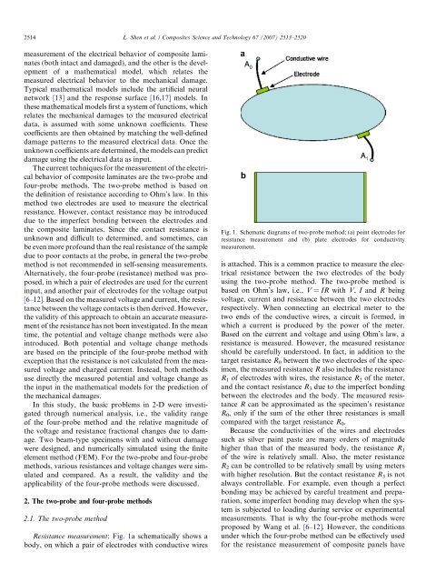
2514 L. Shen et al. / Composites Science <strong>and</strong> Technology 67 (2007) 2513–2520<strong>measurement</strong> <strong>of</strong> <strong>the</strong> <strong>electrical</strong> behavior <strong>of</strong> composite laminates(both intact <strong>and</strong> damaged), <strong>and</strong> <strong>the</strong> o<strong>the</strong>r is <strong>the</strong> development<strong>of</strong> a ma<strong>the</strong>matical model, which relates <strong>the</strong>measured <strong>electrical</strong> behavior to <strong>the</strong> mechanical damage.Typical ma<strong>the</strong>matical models include <strong>the</strong> artificial neuralnetwork [13] <strong>and</strong> <strong>the</strong> response surface [16,17] models. In<strong>the</strong>se ma<strong>the</strong>matical models first a system <strong>of</strong> functions, whichrelates <strong>the</strong> mechanical damages to <strong>the</strong> measured <strong>electrical</strong>data, is assumed with some unknown coefficients. Thesecoefficients are <strong>the</strong>n obtained by matching <strong>the</strong> well-defineddamage patterns to <strong>the</strong> measured <strong>electrical</strong> data. Once <strong>the</strong>unknown coefficients are determined, <strong>the</strong> models can predictdamage using <strong>the</strong> <strong>electrical</strong> data as input.The current techniques for <strong>the</strong> <strong>measurement</strong> <strong>of</strong> <strong>the</strong> <strong>electrical</strong>behavior <strong>of</strong> composite laminates are <strong>the</strong> two-probe <strong>and</strong>four-probe methods. The two-probe method is based on<strong>the</strong> definition <strong>of</strong> <strong>resistance</strong> according to Ohm’s law. In thismethod two electrodes are used to measure <strong>the</strong> <strong>electrical</strong><strong>resistance</strong>. However, contact <strong>resistance</strong> may be introduceddue to <strong>the</strong> imperfect bonding between <strong>the</strong> electrodes <strong>and</strong><strong>the</strong> composite laminates. Since <strong>the</strong> contact <strong>resistance</strong> isunknown <strong>and</strong> difficult to determined, <strong>and</strong> sometimes, canbe even more pr<strong>of</strong>ound than <strong>the</strong> real <strong>resistance</strong> <strong>of</strong> <strong>the</strong> sampledue to poor contacts at <strong>the</strong> probe, in general <strong>the</strong> two-probemethod is not recommended in self-sensing <strong>measurement</strong>s.Alternatively, <strong>the</strong> four-probe (<strong>resistance</strong>) method was proposed,in which a pair <strong>of</strong> electrodes are used for <strong>the</strong> currentinput, <strong>and</strong> ano<strong>the</strong>r pair <strong>of</strong> electrodes for <strong>the</strong> voltage output[6–12]. Based on <strong>the</strong> measured voltage <strong>and</strong> current, <strong>the</strong> <strong>resistance</strong>between <strong>the</strong> voltage contacts is <strong>the</strong>n derived. However,<strong>the</strong> validity <strong>of</strong> this approach to obtain an accurate <strong>measurement</strong><strong>of</strong> <strong>the</strong> <strong>resistance</strong> has not been investigated. In <strong>the</strong> meantime, <strong>the</strong> potential <strong>and</strong> voltage change methods were alsointroduced. Both potential <strong>and</strong> voltage change methodsare based on <strong>the</strong> principle <strong>of</strong> <strong>the</strong> four-probe method wi<strong>the</strong>xception that <strong>the</strong> <strong>resistance</strong> is not calculated from <strong>the</strong> measuredvoltage <strong>and</strong> charged current. Instead, both methodsuse directly <strong>the</strong> measured potential <strong>and</strong> voltage change as<strong>the</strong> input in <strong>the</strong> ma<strong>the</strong>matical models for <strong>the</strong> prediction <strong>of</strong><strong>the</strong> mechanical damages.In this study, <strong>the</strong> basic problems in 2-D were investigatedthrough numerical <strong>analysis</strong>, i.e., <strong>the</strong> validity range<strong>of</strong> <strong>the</strong> four-probe method <strong>and</strong> <strong>the</strong> relative magnitude <strong>of</strong><strong>the</strong> voltage <strong>and</strong> <strong>resistance</strong> fractional changes due to damage.Two beam-type specimens with <strong>and</strong> without damagewere designed, <strong>and</strong> numerically simulated using <strong>the</strong> finiteelement method (FEM). For <strong>the</strong> two-probe <strong>and</strong> four-probemethods, various <strong>resistance</strong>s <strong>and</strong> voltage changes were simulated<strong>and</strong> compared. As a result, <strong>the</strong> validity <strong>and</strong> <strong>the</strong>applicability <strong>of</strong> <strong>the</strong> four-probe methods were discussed.2. The two-probe <strong>and</strong> four-probe methods2.1. The two-probe methodResistance <strong>measurement</strong>: Fig. 1a schematically shows abody, on which a pair <strong>of</strong> electrodes with conductive wiresFig. 1. Schematic diagrams <strong>of</strong> two-probe method; (a) point electrodes for<strong>resistance</strong> <strong>measurement</strong> <strong>and</strong> (b) plate electrodes for conductivity<strong>measurement</strong>.is attached. This is a common practice to measure <strong>the</strong> <strong>electrical</strong><strong>resistance</strong> between <strong>the</strong> two electrodes <strong>of</strong> <strong>the</strong> bodyusing <strong>the</strong> two-probe method. The two-probe method isbased on Ohm’s law, i.e., V = IR with V, I <strong>and</strong> R beingvoltage, current <strong>and</strong> <strong>resistance</strong> between <strong>the</strong> two electrodesrespectively. When connecting an <strong>electrical</strong> meter to <strong>the</strong>two ends <strong>of</strong> <strong>the</strong> conductive wires, a circuit is formed, inwhich a current is produced by <strong>the</strong> power <strong>of</strong> <strong>the</strong> meter.Based on <strong>the</strong> current <strong>and</strong> voltage <strong>and</strong> using Ohm’s law, a<strong>resistance</strong> is measured. However, <strong>the</strong> measured <strong>resistance</strong>should be carefully understood. In fact, in addition to <strong>the</strong>target <strong>resistance</strong> R 0 between <strong>the</strong> two electrodes <strong>of</strong> <strong>the</strong> specimen,<strong>the</strong> measured <strong>resistance</strong> R also includes <strong>the</strong> <strong>resistance</strong>R 1 <strong>of</strong> electrodes with wires, <strong>the</strong> <strong>resistance</strong> R 2 <strong>of</strong> <strong>the</strong> meter,<strong>and</strong> <strong>the</strong> contact <strong>resistance</strong> R 3 due to <strong>the</strong> imperfect bondingbetween <strong>the</strong> electrodes <strong>and</strong> <strong>the</strong> body. The measured <strong>resistance</strong>R can be approximated as <strong>the</strong> specimen’s <strong>resistance</strong>R 0 , only if <strong>the</strong> sum <strong>of</strong> <strong>the</strong> o<strong>the</strong>r three <strong>resistance</strong>s is smallcompared with <strong>the</strong> target <strong>resistance</strong> R 0 .Because <strong>the</strong> conductivities <strong>of</strong> <strong>the</strong> wires <strong>and</strong> electrodessuch as silver paint paste are many orders <strong>of</strong> magnitudehigher than that <strong>of</strong> <strong>the</strong> measured body, <strong>the</strong> <strong>resistance</strong> R 1<strong>of</strong> <strong>the</strong> wire is relatively small. Also, <strong>the</strong> meter <strong>resistance</strong>R 2 can be controlled to be relatively small by using meterswith higher resolution. But <strong>the</strong> contact <strong>resistance</strong> R 3 is notalways controllable. For example, even though a perfectbonding may be achieved by careful treatment <strong>and</strong> preparation,some imperfect bonding may develop when <strong>the</strong> systemis subjected to loading during service or experimental<strong>measurement</strong>s. That is why <strong>the</strong> four-probe methods wereproposed by Wang et al. [6–12]. However, <strong>the</strong> conditionsunder which <strong>the</strong> four-probe method can be effectively usedfor <strong>the</strong> <strong>resistance</strong> <strong>measurement</strong> <strong>of</strong> composite panels have