Double-Wall Cylinders/ Repairable Stainless Steel ... - PW Romex
Double-Wall Cylinders/ Repairable Stainless Steel ... - PW Romex
Double-Wall Cylinders/ Repairable Stainless Steel ... - PW Romex
- No tags were found...

You also want an ePaper? Increase the reach of your titles
YUMPU automatically turns print PDFs into web optimized ePapers that Google loves.
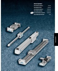
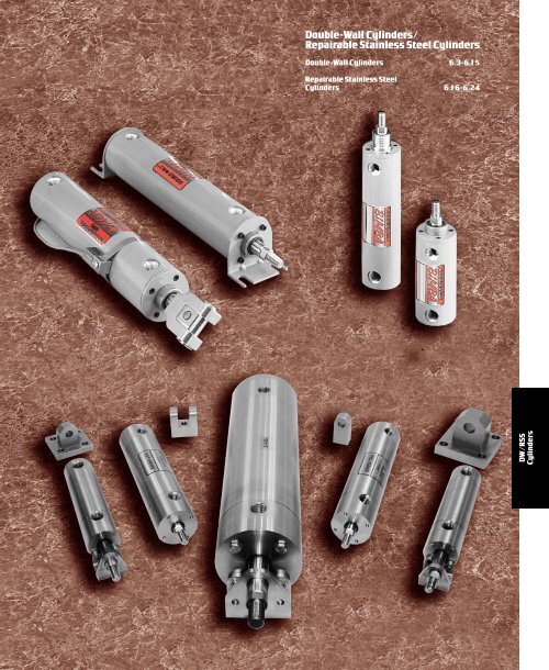
<strong>Double</strong>-<strong>Wall</strong> <strong>Cylinders</strong>/<strong>Repairable</strong><strong>Stainless</strong> <strong>Steel</strong><strong>Cylinders</strong><strong>Double</strong>-<strong>Wall</strong> <strong>Cylinders</strong> 6.3-6.15<strong>Repairable</strong><strong>Stainless</strong> <strong>Steel</strong><strong>Cylinders</strong> 6.16-6.24DW/RSS<strong>Cylinders</strong>
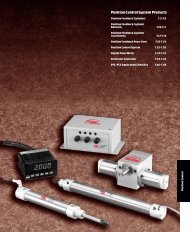
Bimba<strong>Double</strong>-<strong>Wall</strong> <strong>Cylinders</strong>The Bimba <strong>Double</strong>-<strong>Wall</strong> ® Cylinder Does It All !One Basic cylinder converts intosix NFPA mounting styles.End Lugs MS-7Side Lugs MS-2Clevis MP-1Pivot MP-4Front Flange MF-1Rear Flange MF-2DW/RSS<strong>Cylinders</strong>NPT PortsO-RingBody SealBlock VeePiston SealsWave SpringAluminum AlloySelf Aligning HeadBronze Bushing &Lip Seal WiperFour NFPA RodEnd OptionsRetainingRingEpoxy CoatedAluminum Tie-TubePistonBearing Ring304 <strong>Stainless</strong><strong>Steel</strong> BodyRetainingPlateHard ChromePlated Rod6.2
Bimba <strong>Double</strong>-<strong>Wall</strong> ® <strong>Cylinders</strong>HowtoOrderThe Model Number for <strong>Double</strong>-<strong>Wall</strong> ® cylinders consists of three alphanumeric clusters. These designate product type, boresize and stroke length, and options (options are written in the following order: rod end options, and special options with extraextension last). Mounting kits must be ordered as aseparate item, and are shown with their respective bore sizes starting onpage 6.6. Please refer to the charts below for an example of model number DWC-1710-2V. This is a1-1/2" bore, 10" stroke,<strong>Double</strong>-<strong>Wall</strong> cushioned cylinder with asmall male one piece rod end and high temperature option.DWC –1710–2V<strong>Double</strong>-<strong>Wall</strong> <strong>Cylinders</strong>DOUBLE-WALL TYPEBORE SIZEOPTIONSDW - <strong>Double</strong> ActingDWC - <strong>Double</strong> Acting, Cushions Both EndsDWF - <strong>Double</strong> Acting, Front Head CushionDWR - <strong>Double</strong> Acting, Rear CushionDWD - <strong>Double</strong> Acting, <strong>Double</strong> Rod EndDWDC - <strong>Double</strong> Acting, <strong>Double</strong> Rod End,Cushions Both EndsDWDS - <strong>Double</strong> Acting, <strong>Double</strong> Rod End,Cushion One EndDWM (C, F, R) - <strong>Double</strong> Acting, Magnetic PositionSensing (Cushion Optional)DWDM (C, F, R) - <strong>Double</strong> Rod End, Magnetic PositionSensing (Cushion Optional)DW(M)N (C, F, R) - Nose Mount, 1-1/2" and 2" BoresOnly (Cushion and MagnetOptional)DWD(M)N (C, F, R) -Nose Mount, <strong>Double</strong> Rod End,1-1/2" and 3" Bores Only (Cushionand Magnet Optional)17 – 1 1 ⁄ 2 "31 – 2"50 – 2 1 ⁄ 2 "83 – 3 1 ⁄ 4 "125 – 4"STROKELENGTH0.5 – 1 ⁄ 2 "1 – 1"2 – 2"2.5 – 2 1 ⁄ 2 "Etc.GDPX.XXVEEX.XXAXXSRROD END STYLE- Polymer Grease Lubrication- Dual Piston(see page 6.11 (specify stoplength) for details)- High Temperature Seals(300º FMaximum)- Extra Rod Extension(Add to end of model number)- Alternate Cushion ScrewLocations (Locations Available:2and 3for head end, 6and 7for cap end) See dimensionaldrawing of cylinder for portlocations.- <strong>Stainless</strong> <strong>Steel</strong> Rod<strong>Repairable</strong><strong>Stainless</strong> <strong>Steel</strong> <strong>Cylinders</strong>2 - Small Male, One Piece2S - Small Male Stud (Rolled Threads)1 - Large Male, One Piece4 - Female Threads4C - Small Male, One Piece, Coarse Thread (1 1 ⁄2 ", 2" &2 1 ⁄2 "Bores Only)5C - Large Male, One Piece, Coarse Thread (1 1 ⁄2 ", 2" &2 1 ⁄2 "Bores Only)NT - NoThreads(See page 6.5 for dimensions)6.3 ForTechnical Assistance: 800-442-4622
Bimba <strong>Double</strong>-<strong>Wall</strong> ® <strong>Cylinders</strong>List PricesB a s i cM o d e lB a s e P r i c eS t r o k e1A d d e r( p e r i n c h )M o u n t i n gO p t i o n s2 S - S m a l lM a l e S t u dCP e r e n d( P r e f i x C )1 - 1 / 2 " B o r eD P2E E( e a c h 1 / 2 "e a c h e n d )O p t i o n sM( P r e f i xM )S RVV( w i t hc u s h i o n s) 3p e r e n dD W - 1 7 $80.55 $3.05 $5.60 $14.00 $14.55 $1.20 $38.35 $9.45 $42.50 $ 48.20D W D - 1 7 101.75 4.70 11.10 14.00 N/A 2.35 38.35 14.25 56.95 48.20D W N - 1 7 89.35 3.55 5.60 14.00 14.55 1.20 38.35 9.45 42.50 48.20D W D N - 1 7 110.45 6.15 11.10 14.00 N/A 2.35 38.35 14.25 56.95 48.202 " B o r eD W - 3 1 91.45 3.30 5.60 15.05 15.40 1.20 38.35 9.45 52.80 54.30D W D - 3 1 118.10 5.15 11.10 15.05 N/A 2.35 38.35 14.25 67.40 54.30D W N - 3 1 100.30 4.25 5.60 15.05 15.40 1.20 38.35 9.45 52.80 54.30D W D N - 3 1 126.35 6.95 11.10 15.05 N/A 2.35 38.35 14.25 67.40 54.302 - 1 / 2 " B o r eD W - 5 0 103.55 3.70 5.60 16.15 16.85 1.20 38.35 9.45 53.15 55.55D W D - 5 0 129.55 6.50 11.10 16.15 N/A 2.35 38.35 14.25 68.20 55.553 - 1 / 4 " B o r eD W - 8 3 142.30 5.30 12.30 21.55 29.50 1.60 43.15 17.75 57.35 63.85D W D - 8 3 175.50 7.90 24.45 21.55 N/A 3.15 43.15 26.60 71.50 63.854 " B o r eD W - 1 2 5 172.10 6.20 12.30 22.90 34.75 1.60 43.15 17.75 77.10 74.90D W D - 1 2 5 222.10 10.05 24.45 22.90 N/A 3.15 43.15 26.60 89.20 74.90No charge options -2,1,4,4C, 5C, NT, G,AXX.1Consult factory for pricing on fractional strokes and strokes greater than 24".2Pricing based on total stroke, see page 6.11 for details on total stroke.3Price includes cushion adder.Mounting KitsM o d e l 1 - 1 / 2 " 2 " 2 - 1 / 2 " 3 - 1 / 4 " 4 "M S L - $18.45 $22.90 $27.60 $34.40 $ 44.10M E L -12.45 15.00 18.45 26.00 26.90M C -16.35 18.55 20.75 27.15 29.55M P -13.80 15.30 16.50 22.20 24.65M F F A ( A l u m i n u m ) 16.50 18.55 21.90 29.00 36.10M F F S ( S t e e l ) 23.40 25.50 27.95 36.85 41.80M F R A ( A l u m i n u m ) 16.50 18.55 21.90 29.00 36.10M F R S ( S t e e l ) 23.40 25.50 27.95 36.85 41.80AccessoriesRepair KitsK itN u m b erB ore S ize1- 1 / 2 " 2" 2- 1 / 2"3- 1 / 4"4"K - A $7.85 $7.85 $7.85 $14.20 $14.20K - B 12.10 16.20 19.00 26.10 38.00K - C 6.20 6.20 6.20 9.00 9.00K - D 15.60 20.75 24.65 32.95 47.25K - P - M 32.85 34.45 34.65 42.55 50.20H T-99-7 C C3 . 7 0M A G -G- 3 C C6 . 7 5See pages 6.13-6.14 for details.Consult factory for pricing on individual repair parts.M o d e l sD e s c r i p t i o nL i s t P r i c eM o d e l sD e s c r i p t i o nL i s t P r i c e1 - 1 / 2 " , 2 " a n d 2 - 1 / 2 " b o r e s3 - 1 / 4 " a n d 4 " b o r e sA R E - 1A R C - 1A P B - 1A C B - 1A R S - 1A P P - 1D - 1 5 4D - 9 8D - 1 7 9 2 0D - 1 3 3 1R o d E y e$ 1 8 . 5 5R o d C le v is1 9 . 6 5P iv o t B r a c k e t1 8 . 7 5C le v is B r a c k e t2 0 . 2 0R o d S t u d6 . 1 0P iv o t P in6 . 1 5R o d N u t0 . 4 0R o d N u t0 . 5 0N o s e m o u n t f o o t b r a c k e t 10. 2 0N o s e m o u n t m o u n t in g n u t 2 . 3 5A R E - 2A R C - 2A P B - 2A C B - 2A R S - 2A P P - 2D - 3 5 5 6D - 2 5 4 5D - 1 7 9 2 0D - 1 3 3 1R o d E y e$ 2 6 . 8 0R o d C le v is3 3 . 2 5P iv o t B r a c k e t2 9 . 2 5C le v is B r a c k e t3 6 . 6 5R o d S t u d1 3 . 5 5P iv o t P in9 . 8 5R o d N u t0 . 8 0R o d N u t1 . 2 0N o s e m o u n t f o o t b r a c k e t 10. 2 0N o s e m o u n t m o u n t in g n u t 2 . 3 5All prices are F.O.B. Monee, Illinois and are subject to change without notice6.4
Bimba <strong>Double</strong>-<strong>Wall</strong> ® <strong>Cylinders</strong>Dimensions (in.)BRod Thread –2,2S, 1, 4C, 5C Rod Thread –4CADCMMBMMD<strong>Double</strong>-<strong>Wall</strong> <strong>Cylinders</strong>ROD BUSHINGCCAROD BUSHINGCCRod End (1 1 ⁄ 2 ", 2" and 2 1 ⁄ 2 "Bores)R o d E n dS t y l eA B C C C D M M2 . 7 5 1. 1 2 . 3 8 7/ 1 6 - 2 0 U N F . 5 . 6 22S. 7 5 1. 1 2 . 3 8 7/ 1 6 - 2 0 U N F . 5 . 6 21 . 7 5 1. 1 2 . 3 8 1/ 2 - 2 0 U N F . 5 . 6 24 ( t a p p e d ) . 7 5 1. 1 2 . 3 8 7/ 1 6 - 2 0 U N F . 5 . 6 2Rod End (3 1 ⁄ 4 ", 4" Bores)R o d E n dS t y l eA B C C C D M M2 1. 1 2 1.5 . 5 3/ 4 - 1 6 U N F . 8 8 1 . 0 02S1. 1 2 1.5 . 5 3/ 4 - 1 6 U N F . 8 8 1 . 0 01 1. 1 2 1.5 . 5 7/ 8 - 1 4 U N F . 8 8 1 . 0 04 ( t a p p e d ) 1. 1 2 1.5 . 5 3/ 4 - 1 6 U N F . 8 8 1 . 0 0<strong>Repairable</strong><strong>Stainless</strong> <strong>Steel</strong> <strong>Cylinders</strong>4C1. 2 5 1. 0 0 . 1 9 1/ 2 - 1 3 U N C . 5 . 6 25C1. 2 5 1. 0 0 . 1 9 5/ 8 - 1 1 U N C . 5 . 6 2<strong>Double</strong>-<strong>Wall</strong> (no mounting)LB +STROKEYP+STROKEE11V2EE NPT (2)424xDTHREADLOACATED ONBOLT CIRCLE BC3YAPA +STROKEB o r eL B P Y V 2E EY AP A E 1DDd e p t h1- 1 / 2 " 4. 6 2 2. 2 8 1. 6 7 . 4 4 3/ 8 N P T 1. 5 2 2. 5 8 2. 0 0 # 6 - 3 2 0. 5 1 1 . 4 82"4. 6 2 2. 2 8 1. 6 7 . 4 4 3/ 8 N P T 1. 5 2 2. 5 8 2. 3 4 # 8 - 3 2 0. 6 6 1 . 7 52- 1 / 2 " 4. 7 5 2. 4 1 1. 6 7 . 4 4 3/ 8 N P T 1. 5 2 2. 7 0 2. 9 4 # 1 0 - 2 4 0. 6 9 2 . 0 03- 1 / 4 " 5. 6 3 2. 6 2 2. 1 9 . 7 4 1/ 2 N P T 2. 0 0 3. 0 0 3. 6 9 5/ 1 6 - 1 8 0. 7 5 2 . 8 34"5. 6 3 2. 6 2 2. 1 9 . 7 4 1/ 2 N P T 2. 0 0 3. 0 0 4. 4 4 5/ 1 6 - 1 8 0. 7 5 2 . 8 3B C6.5 ForTechnical Assistance: 800-442-4622
Bimba <strong>Double</strong>-<strong>Wall</strong> ® <strong>Cylinders</strong>Side Lug Mount (NFPA MS-2) (in.)SCZB +STROKEP+STROKEEE NPT (2)YV2USE11E2ET42EHSZ(TYP.)SS +STROKEPA +STROKESY(TYP.)XSYASB DIA.BOLT3TSB o r eK i tZ B P S SP A V 2 Y E ES YX SY AS C E 2S ZU S E 1E HE TT SS B1- 1 / 2 " MS L - 1 7 4. 9 0 2. 2 8 2. 8 7 2. 5 8 . 3 1 1. 6 7 3/ 8 N P T 0. 1 9 1. 3 8 1. 5 2 . 1 4 2. 0 0 1. 0 0 3. 5 1 2. 0 0 1. 0 0 . 1 3 2. 7 5 . 3 82"MS L - 3 1 4. 9 2 2. 2 8 2. 8 7 2. 5 8 . 3 1 1. 6 7 3/ 8 N P T 0. 1 9 1. 3 8 1. 5 2 . 1 6 2. 3 4 1. 0 0 4. 0 1 2. 3 4 1. 2 5 . 1 3 3. 2 5 . 3 82- 1 / 2 " MS L - 5 0 5. 1 2 2. 4 1 3. 0 0 2. 7 0 . 2 6 1. 6 7 3/ 8 N P T 0. 1 9 1. 3 8 1. 5 2 . 1 9 3. 0 0 1. 0 0 4. 5 1 2. 9 4 1. 4 9 . 1 8 3. 7 5 . 3 83- 1 / 4 " MS L - 8 3 6. 1 1 2. 6 2 3. 2 5 3. 0 0 . 4 9 2. 1 9 1/ 2 N P T 0. 1 6 1. 8 8 2. 0 0 . 2 3 3. 7 5 1. 2 5 5. 7 6 3. 6 9 1. 8 7 . 2 5 4. 7 5 . 5 04"MS L - 1 2 5 6. 1 7 2. 6 2 3. 2 5 3. 0 0 . 4 3 2. 1 9 1/ 2 N P T 0. 1 6 1. 8 8 2. 0 0 . 2 3 4. 5 0 1. 2 5 6. 5 1 4. 4 4 2. 2 4 . 3 1 5. 5 0 . 5 0End Lug Mount (NFPA MS-7) (in.)XE +STROKEP+STROKEEE NPT (2)YV2E1BODY DIA.1E242ETEHAOPA +STROKEYA3RALSE +STROKEEB DIA. BOLTB o r eK i tX E P P AS E V 2 Y E EY AA OA L E 2 E 1E HE TE BR1- 1 / 2 " ME L - 1 7 5. 3 8 2. 2 8 2. 5 8 5. 1 2 . 3 1 1. 6 7 3/ 8 N P T 1. 5 2 . 2 6 . 7 5 2. 0 0 2. 0 0 1. 0 0 . 1 3 . 2 5 1 . 4 32"ME L - 3 1 5. 5 6 2. 2 8 2. 5 8 5. 5 0 . 3 1 1. 6 7 3/ 8 N P T 1. 5 2 . 3 2 . 9 4 2. 3 4 2. 3 4 1. 2 5 . 1 3 . 3 1 1 . 8 42- 1 / 2 " ME L - 5 0 5. 8 1 2. 4 1 2. 7 0 5. 8 8 . 2 6 1. 6 7 3/ 8 N P T 1. 5 2 . 3 0 1. 0 7 3. 0 0 2. 9 4 1. 4 9 . 1 8 . 3 1 2 . 1 93- 1 / 4 " ME L - 8 3 6. 5 0 2. 6 2 3. 0 0 6. 0 0 . 4 9 2. 1 9 1/ 2 N P T 2. 0 0 . 3 8 1. 1 8 3. 7 5 3. 6 9 1. 8 7 . 2 5 . 3 8 2.764"ME L - 1 2 5 6. 6 3 2. 6 2 3. 0 0 6. 2 5 . 4 3 2. 1 9 1/ 2 N P T 2. 0 0 . 3 7 1. 3 2 4. 5 0 4. 4 4 2. 2 4 . 3 1 . 3 8 3 . 3 26.6
Bimba <strong>Double</strong>-<strong>Wall</strong> ® <strong>Cylinders</strong>Clevis Mount (NFPA MP-1) (in.)6E158CDPINDIA.FLP+STROKEEE NPT (2)YV2<strong>Double</strong>-<strong>Wall</strong> <strong>Cylinders</strong>MRAD.CW7CBCWLPA +STROKEXD +STROKEYAB o r eK i t P P AX D Y V 2E EY AF LC D M L E 11- 1 / 2 " MC - 1 7 2. 2 8 2. 5 8 5. 3 8 1. 6 7 . 8 2 3/ 8 N P T 1. 5 2 . 7 5 . 5 0 . 4 4 . 5 6 2. 0 0 . 7 6 . 5 12"MC - 3 1 2. 2 8 2. 5 8 5. 3 8 1. 6 7 . 8 2 3/ 8 N P T 1. 5 2 . 7 5 . 5 0 . 4 4 . 5 6 2. 3 4 . 7 6 . 5 12- 1 / 2 " MC - 5 0 2. 4 1 2. 7 0 5. 5 0 1. 6 7 . 8 2 3/ 8 N P T 1. 5 2 . 7 5 . 5 0 . 5 0 . 5 6 2. 9 4 . 7 6 . 5 13- 1 / 4 " MC - 8 3 2. 6 2 3. 0 0 6. 8 8 2. 1 9 1. 2 4 1/ 2 N P T 2. 0 0 1. 2 6 . 7 5 . 6 9 . 8 8 3. 6 9 1. 2 6 . 6 2C BC W<strong>Repairable</strong><strong>Stainless</strong> <strong>Steel</strong> <strong>Cylinders</strong>4"MC - 1 2 5 2. 6 2 3. 0 0 6. 8 8 2. 1 9 1. 2 4 1/ 2 N P T 2. 0 0 1. 2 6 . 7 5 . 6 9 . 8 8 4. 4 4 1. 2 6 . 6 2Pivot Mount (NFPA MP-4) (in.)P+STROKEYE15CDDIA.PIVOTFLEE NPT (2)V2687CBMRAD.LPA +STROKEYAXD +STROKEB o r eK i t P P AX D Y V 2E EY AF LC D M L E 1C B1- 1 / 2 " MP - 1 7 2. 2 8 2. 5 8 5. 7 5 1. 6 7 . 4 4 3/ 8 N P T 1. 5 2 . 1 9 . 5 0 . 5 0 . 9 3 2. 0 0 . 7 52"MP - 3 1 2. 2 8 2. 5 8 5. 7 5 1. 6 7 . 4 4 3/ 8 N P T 1. 5 2 . 1 9 . 5 0 . 5 0 . 9 3 2. 3 4 . 7 52- 1 / 2 " MP - 5 0 2. 4 1 2. 7 0 5. 8 7 1. 6 7 . 4 4 3/ 8 N P T 1. 5 2 . 1 9 . 5 0 . 5 0 . 9 3 2. 9 4 . 7 53- 1 / 4 " MP - 8 3 2. 6 2 3. 0 0 7. 5 0 2. 1 9 . 7 4 1/ 2 N P T 2. 0 0 . 5 0 . 7 5 . 6 9 1. 3 8 3. 6 9 1 . 2 54"MP - 1 2 5 2. 6 2 3. 0 0 7. 5 0 2. 1 9 . 7 4 1/ 2 N P T 2. 0 0 . 5 0 . 7 5 . 6 9 1. 3 8 4. 4 4 1 . 2 56.7 ForTechnical Assistance: 800-442-4622
Bimba <strong>Double</strong>-<strong>Wall</strong> ® <strong>Cylinders</strong>Front Flange Mount (NFPA MF-1) (in.)ZB +STROKEP+STROKEEE NPT (2)YWUFE11E2R42PA +STROKEYAFHFBBOLTDIA.3TFB o r eK i tZ B P P A Y W E EY AF HU F E 1 E 2 R T FF B1 - 1 / 2 "2 "2 - 1 / 2 "3 - 1 / 4 "4 "M F F A - 1 7M F F S - 1 7M F F A - 3 1M F F S - 3 1M F F A - 5 0M F F S - 5 0M F F A - 8 3M F F S - 8 3M F F A - 1 2 5M F F S - 1 2 54. 6 2 2. 2 8 2. 5 8 1. 6 7 . 6 3 3/ 8 N P T 1. 5 2 . 3 8 3. 3 8 2. 0 0 2. 0 0 1. 4 3 2. 7 5 . 2 54. 6 2 2. 2 8 2. 5 8 1. 6 7 . 6 3 3/ 8 N P T 1. 5 2 . 3 8 4. 1 2 2. 3 4 2. 5 0 1. 8 4 3. 3 8 . 3 14. 7 5 2. 4 1 2. 7 0 1. 6 7 . 6 3 3/ 8 N P T 1. 5 2 . 3 8 4. 6 2 2. 9 4 3. 0 0 2. 1 9 3. 8 8 . 3 15. 6 3 2. 6 2 3. 0 0 2. 1 9 . 7 5 1/ 2 N P T 2. 0 0 . 6 2 5. 5 0 3. 6 9 3. 7 5 2. 7 6 4. 6 9 . 3 85. 6 3 2. 6 2 3. 0 0 2. 1 9 . 7 5 1/ 2 N P T 2. 0 0 . 6 2 6. 2 5 4. 4 4 4. 5 0 3. 3 2 5. 4 4 . 3 8Rear Flange Mount (NFPA MF-2) (in.)ZF +STROKEUFE15P+STROKEEE NPT (2)YV268RE27TFFBBOLTDIA.FHPA +STROKEYAB o r eK i tZ F P P A Y V 2E EY AF HU F E 1 E 2 R T FF B1 - 1 / 2 "2 "2 - 1 / 2 "3 - 1 / 4 "4 "M F R A - 1 7M F R S - 1 7M F R A - 3 1M F R S - 3 1M F R A - 5 0M F R S - 5 0M F R A - 8 3M F R S - 8 3M F R A - 1 2 5M F R S - 1 2 55. 0 0 2. 2 8 2. 5 8 1. 6 7 . 4 4 3/ 8 N P T 1. 5 2 . 3 8 3. 3 8 2. 0 0 2. 0 0 1. 4 3 2. 7 5 . 2 55. 0 0 2. 2 8 2. 5 8 1. 6 7 . 4 4 3/ 8 N P T 1. 5 2 . 3 8 4. 1 2 2. 3 4 2. 5 0 1. 8 4 3. 3 8 . 3 15. 1 2 2. 4 1 2. 7 0 1. 6 7 . 4 4 3/ 8 N P T 1. 5 2 . 3 8 4. 6 2 2. 9 4 3. 0 0 2. 1 9 3. 8 8 . 3 16. 2 5 2. 6 2 3. 0 0 2. 1 9 . 7 4 1/ 2 N P T 2. 0 0 . 6 2 5. 5 0 3. 6 9 3. 7 5 2. 7 6 4. 6 9 . 3 86. 2 5 2. 6 2 3. 0 0 2. 1 9 . 7 4 1/ 2 N P T 2. 0 0 . 6 2 6. 2 5 4. 4 4 4. 5 0 3. 3 2 5. 4 4 . 3 86.8
Bimba <strong>Double</strong>-<strong>Wall</strong> ® <strong>Cylinders</strong><strong>Double</strong> End Rod Cylinder Series DWD(in.)<strong>Double</strong>-<strong>Wall</strong> <strong>Cylinders</strong>Basic <strong>Double</strong>-End Rod CylinderFlange Mount (NFPA MF-1)E1BODY DIA.DBAAMMV1CKKYYAZM +2XSTROKEP+STROKEEE NPT (2)LD +STROKEPA +STROKEZL +STROKESide Lug Mount (NFPA MS-2)UFE112 4 R E23TFFBBOLT DIA.V3WWFMounting Kit #MFF (See page 6.4 for pricing)End Lug Mounts (NFPA MS-7)F<strong>Repairable</strong><strong>Stainless</strong> <strong>Steel</strong> <strong>Cylinders</strong>US1V21V2EH2 43TSE2ETSB DIA.BOLTXSSS +STROKE2 4 E2EHET3REB DIA.BOLTSE +STROKEXE +STROKEMounting Kit #MSL (See page 6.4 for pricing)Mounting Kit #MEL (See page 6.4 for pricing)B o r eA A B C D E BE EE HE T E 1 E 2 F F BK KL DM M P P AR1- 1 / 2 " 1. 4 8 1. 1 2 4 . 3 8 . 5 6 . 2 5 3/8 1. 0 0 . 1 3 2. 0 0 2. 0 0 . 3 8 . 2 5 7/ 1 6 - 2 0 4. 1 6 . 6 2 2. 4 4 2. 7 4 1 . 4 32"1. 7 5 1. 1 2 4 . 3 8 . 5 6 . 3 1 3/8 1. 2 5 . 1 3 2. 3 4 2. 5 0 . 3 8 . 3 1 7/ 1 6 - 2 0 4. 1 6 . 6 2 2. 4 4 2. 7 4 1 . 8 42- 1 / 2 " 2. 0 0 1. 1 2 4 . 3 8 . 5 6 . 3 1 3/8 1. 4 9 . 1 8 2. 9 4 3. 0 0 . 3 8 . 3 1 7/ 1 6 - 2 0 4. 1 6 . 6 2 2. 4 4 2. 7 4 2 . 1 93- 1 / 4 " 2. 8 3 1. 4 9 9 . 5 0 . 8 8 . 3 8 1/2 1. 8 7 . 2 5 3. 6 9 3. 7 5 . 6 2 . 3 8 3/ 4 - 1 6 4. 6 4 1. 0 0 2. 7 5 3. 1 2 2 . 7 64"2. 8 3 1. 4 9 9 . 5 0 . 8 8 . 3 8 1/2 2. 2 4 . 3 1 4. 4 4 4. 5 0 . 6 2 . 3 8 3/ 4 - 1 6 4. 6 4 1. 0 0 2. 7 5 3. 1 2 3 . 3 2B O R ES BS ES ST FT SU FU S V 1 V 2 V 3 W W FX EX S Y Y AZ LZ M1- 1 / 2 " . 3 8 5. 4 6 3. 2 2 2. 7 5 2. 7 5 3. 3 8 3. 5 1 . 4 4 . 3 1 . 2 5 . 6 2 1. 0 0 5. 7 2 1. 3 8 1. 6 7 1. 5 2 4. 9 6 5 . 7 72". 3 8 5. 8 4 3. 2 2 3. 3 8 3. 2 5 4. 1 2 4. 0 1 . 4 4 . 3 1 . 2 5 . 6 2 1. 0 0 5. 9 0 1. 3 8 1. 6 7 1. 5 2 4. 9 6 5 . 7 72- 1 / 2 " . 3 8 6. 1 0 3. 2 2 3. 8 8 3. 7 5 4. 6 2 4. 5 1 . 4 4 . 2 6 . 2 5 . 6 2 1. 0 0 6. 0 3 1. 3 8 1. 6 7 1. 5 2 4. 9 6 5 . 7 73- 1 / 4 " . 5 0 6. 2 6 3. 5 1 4. 6 9 4. 7 5 5. 5 0 5. 7 6 . 7 4 . 4 9 . 2 5 . 7 5 1. 3 7 6. 7 6 1. 8 8 2. 1 9 2. 0 0 5. 8 9 7 . 1 34". 5 0 6. 5 1 3. 5 1 5. 4 4 5. 5 0 6. 2 5 6. 5 1 . 7 4 . 4 3 . 2 5 . 7 5 1. 3 7 6. 8 9 1. 8 8 2. 1 9 2. 0 0 5. 8 9 7 . 1 3Note: When ordering Cushions Both Ends specify DWDC –One End DWDS, See page 6.3.EE will provide extra extension on both ends.6.9 ForTechnical Assistance: 800-442-4622
Bimba <strong>Double</strong>-<strong>Wall</strong> ® <strong>Cylinders</strong><strong>Double</strong>-<strong>Wall</strong> ® Front Nose Mounting (in.)Single End Rod2.00 (DWN-170)2.34 (DWN-310).67.533/8 NPT (2)4.70 +STROKE1.761.61.89.19CUSHION SCREW (2)1.055/1.059 DIA. PILOT1"-14 UNS1.761.615.94 +STROKE1.761.612.00 (DWN-170)2.34 (DWN-310)<strong>Double</strong> End Rod.19.893/8 NPT (2).89.191"-14 UNS(TYP.)1.055/1.059 DIA.PILOT (TYP.)CUSHIONSCREW (2)Foot Bracket (D-17920)Accessory for Nose Mount1.25 R1.062 DIA.3.75Mounting Nut (D-1331)1.50 HEX.553.001.75.25.751.001.62.44 1.441.44.341-14UNS-2B<strong>Double</strong>-<strong>Wall</strong> Engineering SpecificationsTie Tube:Cylinder Body:Piston Rod:Seals:Lubrication:Temperature:Pressure Rating:Life:Stroke Maximum:Epoxy coated AluminumSmooth 304 stainless steelHard Chrome Plated standard; 303 stainless optionalBuna NStandard; High Temperature Fluoroelastomer optionalHT-99 standard; Polymer grease option-20º to 200º Fstandard; 0º to 300º Fwith high temperature option200 psi; 150 psi with high temperature option1400 miles of travel when lubricated (Lubrication every 500 milesrecommended72" (strokes beyond 72" require anapplication review)6.10
Bimba <strong>Double</strong>-<strong>Wall</strong> ® <strong>Cylinders</strong>Class 1Class 2Class 3Class 4<strong>Double</strong>-<strong>Wall</strong> ® Long Stroke Cylinder SelectionApplication of Long Stroke <strong>Cylinders</strong> are controlled by twofactors: column strength of piston rod and mountingconfiguration. Dual Piston construction provides neededadditional bearing surface through the cycle of the cylinder.Determining Mounting ClassDual Piston Stop Length CalculationDual Pistons consist of mounting two pistons on the rod,separated acalculated distance to provide the requiredstop length. Available in one inch increments, required stoplengths are determined from mounting class and strokeinformation.Mounting StyleSide LugEnd LugFlangeSide LugEnd LugFlangePivotClevisSide LugEnd LugFlangeRod End ConnectionRigidly guided,pivotedPivoted, supportedbut not rigidly guidedPivoted, supportedFree end unguidedand unsupportedSelect mounting class. Move over to the column showing astroke length equal to or less than required. Figure attop ofcolumn is required Dual Piston stop length. Examples: Class 2, 62" stroke length =2"stop length. Class 3, 62" -5"stoplength. All lengths shown here are in inches.<strong>Double</strong>-<strong>Wall</strong> <strong>Cylinders</strong><strong>Repairable</strong><strong>Stainless</strong> <strong>Steel</strong> <strong>Cylinders</strong>M o u n t i n gC l a s sColumn Strength LimitationsD u a l P i s t o n – S t o p L e n g t h R e q u i r e d1 2 3 4 5 6 7 8 9 1 0 1 1 1 21 6488110 1 3 02 46627893108 122 1 3 63 25344351596774818895101 1 0 84 16222828404651566166707 4Net (effective) stroke stop length =Gross stroke of cylinder. Mounting dimensions are determined from gross stroke.Consult your local distributor for Dual Piston Pricing.Select mounting class, rod diameter, and stroke length in inches: read maximum push force in pounds for that combination.Where novalues is shown, the rod issafe for the maximum rated cylinder push force.R o d D i a m e t e r /I n c h e s S t r o k eC l a s s 1 C l a s s 2 C l a s s 3 C l a s s 45 / 8 " 1 " 5 / 8 " 1 " 5 / 8 " 1 " 5 / 8 " 1 "108 2 015820360 2 3 9 020460200 1 3 4 025290 19 4 0 130 8 6 030820200 13 4 0 906 0 040820460110 750 503 3 050540290 19 4 0 70480 302 1 060360 23 9 0 200 13 4 0 50330 201 5 0WeightsB o r eA p p r o x i m a t e W e i g h t s ( l b s . )B a s e W e i g h tA d d e r p e r i n c ho f s t r o k e1- 1 / 2 " ( 1 7 ) 1. 3 60 . 1 92"( 3 1 ) 1. 8 10 . 2 22- 1 / 2 " ( 5 0 ) 2.90 . 3 13- 1 / 4 " ( 8 3 ) 5. 6 20 . 5 14"( 1 2 5 ) 7.50 . 5 76.11 ForTechnical Assistance: 800-442-4622
Bimba <strong>Double</strong>-<strong>Wall</strong> ® <strong>Cylinders</strong>AccessoriesRod EyeB o r e P a r t #1 ¹ / ₂ - 2 ¹ / ₂ A R E - 13 ¹ / ₄ - 4 A R E - 2(For -2 Rod Endstyle only)CDCACDCDACDCBKKRod Stud(Rolled Threads)B o r e P a r t #1 ¹ / ₂ - 2 ¹ / ₂ A R S - 13 ¹ / ₄ - 4 A R S - 2MSKLRod ClevisB o r e P a r t #1 ¹ / ₂ - 2 ¹ / ₂ A R C - 13 ¹ / ₄ - 4 A R C - 2(Nickel <strong>Steel</strong>)Includes CaseHardened Pin(For -2 Rod Endstyle only)KKCWCLCBCWCDCDCECDERACDKKCase HardenedPivot Pin with RingsB o r e P a r t #1 ¹ / ₂ - 2 ¹ / ₂ A P P - 13 ¹ / ₄ - 4 A P P - 2Pivot BracketB o r e P a r t #FL1F1LR1ECBCLCD1 ¹ / ₂ - 2 ¹ / ₂ A P B - 13 ¹ / ₄ - 4 A P B - 2Clevis BracketB o r e P a r t #1 ¹ / ₂ - 2 ¹ / ₂ A C B - 1F2FL2LR2CDMRAA(BOLTCIRCLE)EDD (BOLT DIA.)ECLCW CB CWHexNut (in.)P a r tH e xT H DT H KD - 1 5 4 0. 6 9 7/ 1 6 " - 2 0 0 . 2 53 ¹ / ₄ - 4 A C B - 2(Includes CaseHardened Pin)MRCDAA(BOLTCIRCLE)DD (BOLT DIA.)ED - 9 8 0. 7 5 1/ 2 " - 2 0 0 . 3 1D - 3 5 5 6 1. 1 2 3/ 4 " - 1 6 0 . 4 2D - 2 5 4 5 1. 3 1 7/ 8 " - 1 4 0 . 4 8Accessories Dimensions (in.)B o r eA A AC AC BC DC EC WC LD D1- 1 / 2 " , 2 " , 2 - 1 / 2 " 0. 7 5 2 1.5 0. 7 5 0.5 1.5 0.5 1. 7 5 0 . 1 93- 1 / 4 " , 4 " 1. 1 2 2. 8 3 2. 0 6 1. 2 5 0. 7 5 2. 3 8 0. 6 2 2.5 0 . 3 1 2B o r eE E R F 1 F 2 F L 1 F L 2K KK L L R 1 L R 2M RM R1- 1 / 2 " , 2 " , 2 - 1 / 2 " 1. 8 8 0. 5 9 0. 3 8 0. 3 8 1. 1 2 1. 1 2 7/ 1 6 " - 2 0 2. 1 2 0. 7 4 5 0. 7 4 5 0.5 1 . 53- 1 / 4 " , 4 " 2. 7 5 0. 8 4 0.5 0. 3 8 1. 8 8 1. 2 5 3/ 4 " - 1 6 3. 2 7 1.1 0. 8 5 0. 6 8 2 . 2 56.12
Bimba <strong>Double</strong>-<strong>Wall</strong> ® <strong>Cylinders</strong>HowtoOrder Repair Parts &KitsBasic DWSeries*<strong>Double</strong>-<strong>Wall</strong> <strong>Cylinders</strong>Basic DWDSeries* Used in mostmounting kits and onall 3 1 ⁄ 4 "and 4" borebasic cylinders.<strong>Repairable</strong><strong>Stainless</strong> <strong>Steel</strong> <strong>Cylinders</strong>**Used on all 3-1/4"and 4" bore basiccylinders.Individual Repair Parts and Kits are listed onpage 6.14. When ordering, indicate the quantity desired, the partnumber orkit designation, and the cylinder model number onwhich the part is to be used. For example, aCushionAdjusting Screw for a1-1/2" bore, 10" stroke, <strong>Double</strong>-<strong>Wall</strong> cylinder, Cushioned Both Ends, and aSmall Male OnePiece Rod End, would be ordered as follows:Quantity Part orKit Number Model Number1 P-15 DWC-1710-2ABasic Repair Kit for the same cylinder would be: 1 K-B DWC-1710-2See page 6.14 for Repair Parts and page 6.4 for Repair Kits Pricing.6.13 ForTechnical Assistance: 800-442-4622
Bimba <strong>Double</strong>-<strong>Wall</strong> ® <strong>Cylinders</strong>Repair Parts ListN o .P- 1P- 2P- 3P- 4P a r t D e s c r i p t i o nD WD W FD W RQ u a n t i t y b y M o d e l T y p eD W CD W DD W D FD W D CRod1 1 1Pis t o n1 1 1Pis t o n S e a l2 2 2 2 2 2 2Pis t o n B e a r in g R in g1 1 1 1 1 1 1P - 5Fr e e T h r e a d N u t *1 1 1P - 6Fr e e T h r e a d R in g *4 4 4P - 8O- R in g ( F r e e T h r e a d ) *1 1 1P - 9Ro d S e a l*1 1 1 1 2 2 2P - 1 0Cu s h io n S e a l*1 1 2 1 2P - 1 1Cu s h io n S le e v e ( H e a d E n d ) *1 1P - 1 2Cu s h io n S le e v e ( C a p E n d ) *1P - 1 3Cu s h io n B / U W a s h e r *1 1 2 1 2P - 1 4Cu s h io n R e t a in in g R in g *1 1 2 1 2P- 1 5Cu s h io n A d ju s t in g S c r e w1 1 2 1 2P - 1 8O- R in g ( C u s h io n S c r e w s ) *1 1 2 1 2P- 1 9P- 2 0P- 2 1P- 2 2Tie - T u b e1 1 1 1 1 1 1St a in le s s S t e e l B o d y1 1 1 1 1 1 1He a d1 1 1 1 2 2 2Cap1 1 1 1P - 2 3 O- R in g ( S t a in le s s S t e e l B o d y ) 2 2 2 2 2 2 2P- 2 4Wa v e S p r in g1 1 1 1 2 2 2P - 2 5Re t a in in g R in g ( T ie - T u b e )2 2 2 2 2 2 2P - 2 6Ro d W ip e r ( w / o B u s h in g ) *1 1 1 1 2 2 2P - 2 7 Ro d W ip e r B u s h in g A s s e m b ly * 1 1 1 1 2 2 2P- 2 8P- 2 9Sp a c e r1 1 1 1 2 2 2Re t a in in g P la t e1 1 1 1 2 2 2P - 3 0Sc r e w ( R e t . P la t e )4 4 4 4 8 8 8P- 4 3P- 5 8HT - 9 9 - 7 C CMa g - G - 3 C CCu s h io n S le e v e1 1 2Pis t o n / R o d A s s e m b ly1 1 1 1Lu b r ic a t io n1 1 1 1 1 1 1Po ly m e r G r e a s e L u b r ic a n t 1 1 1 1 1 1 1*Parts and kits that are common to multiple bore sizes, which are available in two sizes: 1-1/2", 2", 2-1/2" boresare designated as –S. 3-1/4", 4" bores are designated as–L.Repair KitsB a s i c R e p a i r K i t ( K - B - _ ) I n c l u d e s :P - 2 5 Re t a in in g R in g ( T ie - T u b e )2P- 2 3P- 2 4P- 3P- 4O- r in g2Wa v e S p r in g1Pis t o n S e a l2Pis t o n B e a r in g R in g1D W D B a s i c R e p a i r K i t ( K - D - _ ) I n c l u d e s :P - 2 5 Re t a in in g R in g ( T ie - T u b e )2P- 2 3P- 2 4P- 3P- 4O- r in g2Wa v e S p r in g2Pis t o n S e a l2Pis t o n B e a r in g R in g1P- 1 0P- 1 3P- 1 4P- 1 5C u s h i o n R e p a i r K i t ( K - C - _ ) I n c l u d e s :Cu s h io n S e a l1Cu s h io n B / U W a s h e r1Cu s h io n R e t a in in g R in g1Cu s h io n A d ju s t in g S c r e w1P - 1 8 O- R in g ( C u s h io n S c r e w s )1P- 2 7P- 9P- 3 3P- 3 4P- 4R o d S e a l R e p a i r K i t ( K - A - _ ) I n c l u d e s :Ro d W ip e r B u s h in g A s s e m b ly1Ro d S e a l1M R S P i s t o n R e p a i r K i t ( K - P - M - _ ) I n c l u d e s :Pis t o n S e a l A s s e m b ly1Ma g n e t1Pis t o n B e a r in g R in g16.14
Bimba <strong>Double</strong>-<strong>Wall</strong> ® <strong>Cylinders</strong>Important <strong>Double</strong>-<strong>Wall</strong> ® InformationPiston Rod Diameter –5/8" and 1" diameter rods are standard.These rods are made of high strength steel and are suitable formost applications. On long stroke, high thrust applications cautionshould be exercised and the column strength and stop lengthchart on page 6.11 should be reviewed.Material –Hard chrome plated rods are supplied as standard onall models except 1-1/2" MRS, which are 303 stainless steel.Special materials such as 303 stainless steel are available onrequest.Rod End Options –Bimba offers six popular NFPA rod end styles(see page 6.5). Bimba considers the one-piece male style #2, asthe primary standard rod end. Asmall male rod stud, style #2S, isalso offered as astandard option. The stud is made from 125,000P.S.I. min. yield steel and is roll threaded for increased strength.Special rod ends with different thread lengths, pitch and class areavailable upon request.Cushions –The <strong>Double</strong>-<strong>Wall</strong> ® offers exclusive <strong>Stainless</strong>-Cushions ® ,type 304 stainless steel sleeves which enhancecushion performance and life. The cushion seal is contained onthe piston rod for easy inspection and replacement whennecessary. Air cushions may be specified on either or both endswithout changing the cylinder’s overall length.The cushion design allows for aflush mounted adjustment screweven in the fully open setting. Unless otherwise specified,cushioned models are shipped with the adjustment screwslocated in positions 4and 8asshown on the cylinder dimensionaldrawings.Adjustment screws may be ordered in other than standardpositions at no additional charge. Simply add these designationsas the last digits of the model number:A2 –Head Adjustment Screw –Position 2A3 –Head Adjustment Screw –Position 3A6 –Cap Adjustment Screw –Position 6A7 –Cap Adjustment Screw –Position 7A26 –Adjustment Screws –Positions 2and 6A37 –Adjustment Screws –Positions 3and 7Mountings –<strong>Double</strong>-<strong>Wall</strong> cylinders utilize easy to assemble “bolton” mounting kits. Basic cylinders (less mountings) and mountingkits are ordered and shipped as separate items. All necessaryhardware iscontained in the kit. The clevis mounting kit forexample contains the clevis cap, pivot pin, retaining rings, andmounting cap screws.The clevis and pivot caps are high strength aluminum die castingsand have oil-filled bronze bushings. Side and end lug kits containbrackets which are stamped from high strength steel. Flange kitsare offered in both steel and aluminum. All mountings are epoxycoated.“Bolt on” <strong>Double</strong>-<strong>Wall</strong> mounting kits give your local BIMBADistributor inventory versatility allowing him to stock Basiccylinders of various popular strokes and bores without comittingthem exclusively to one mounting style. This means greater “offthe shelf” availability for you.Delivery –Ordering standard cylinders with the primary standardstyle #2 rod end will allow you to take advantage of asubstantiallocal Distributor stock of <strong>Double</strong>-<strong>Wall</strong> cylinders. Avery large stockof cushioned (both ends) and non-cushioned finished cylinders isalways maintained at our Monee, Illinois plant. In addition wemaintain avast inventory of finished heads, caps, rods, etc. forquick assembly of your optional feature ornon-standard strokerequirement.Specials –Bimba Manufacturing welcomes the opportunity tocustom design acylinder to meet your exact specifications andrequirements. As aleading manufacturer of custom specialcylinders, we can provide the engineering expertise to help youwith whatever design problem you face. We also maintain aspecials department within our manufacturing facilities to assureyou of the most expedient delivery possible. Please contact yourlocal Bimba Distributor or Customer Service Department withdetails of your special requirement.<strong>Double</strong>-<strong>Wall</strong> <strong>Cylinders</strong><strong>Repairable</strong><strong>Stainless</strong> <strong>Steel</strong> <strong>Cylinders</strong>6.15 ForTechnical Assistance: 800-442-4622
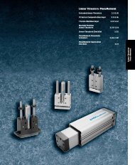
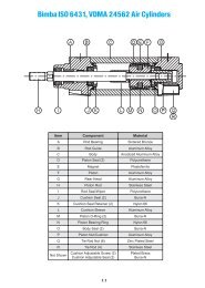
Bimba <strong>Repairable</strong> <strong>Stainless</strong> <strong>Steel</strong> <strong>Cylinders</strong>Component Description OperatingSpecifications USDA Accepted(Option U, see page 6.17 and 6.20) 6.16
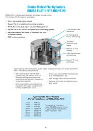
Bimba <strong>Repairable</strong> <strong>Stainless</strong><strong>Steel</strong><strong>Cylinders</strong>HowtoOrderBore Size1-1/2"2"2-1/2"3-1/4"4"5"6"8"RS -1-1/2X4 -MP2 UStroke4=4"(0 -24")Mounting StylesMXO - Tapped Both EndsMXF - Tapped FrontMXR - Tapped RearMP2 - Clevis RearMP4 - Pivot RearOptionsB - Bumpers 1FC - Fixed Cushions 5KK3 - Female Rod Thread 2M - Magnetic Piston 5NT - Non-threaded Rod 5P - Prox. Switch Both Ends 5TW - Piston Bearing Strip 35SP - 303 <strong>Stainless</strong> <strong>Steel</strong> Piston 5U - USDA Approved Options 4V - High Temperature SealsEE - Extra Rod ExtensionOption Notes:Option (B) Bumpers and Option (FC)Cushions are not avalid combination.Option (B) Bumpers and Option (P) Prox.Switches are not avalid combination.If Option (B) and Option (V) are ordered incombination, the standard Bumpermaterial will be used in bore sizes 5, 6,and 8".Option (M) Magnetic Piston and Option (V)High Temperature Seals should bespecified for chemical compatibilityrequirements only. The piston magnetis nitrile based, hence the temperaturerating remains at 200 degrees F.<strong>Double</strong>-<strong>Wall</strong> <strong>Cylinders</strong><strong>Repairable</strong><strong>Stainless</strong> <strong>Steel</strong> <strong>Cylinders</strong>List PricesBoreTappedBoth Ends(MXO)TappedFront(MXF)TappedRear(MXR)RearClevis(MP2)RearPivot(MP4)Adderper 1"StrokeBumpersBoth Ends(B) 1FixedCushions(FC) 5MagneticPiston(M) 5ProxSwitches(P) 5PistonBearing Strip(TW) 35303 SSPiston(SP) 5USDA High TempOptions Seals(U) 4 (V)ExtraRod Ext.(EE)1-1/2" (17) $265.20 $251.95 $251.95 $340.15 $337.30 $8.10 $8.85 $49.35 $17.35 $198.45 $10.95 $33.70 $101.45 $29.25 $4.65/inch2" (31) 297.80 284.55 284.55 377.80 373.75 10.80 14.00 54.20 20.25 198.45 11.55 38.50 105.15 33.95 4.65/inch2-1/2" (50) 323.50 310.25 310.25 408.15 402.95 12.05 14.00 60.75 20.25 198.45 12.00 39.05 106.30 37.35 4.65/inch3-1/4" (83) 408.75 395.50 395.50 501.00 494.65 13.90 19.35 65.95 36.10 198.45 13.00 49.65 120.60 70.50 6.70/inch4" (125) 474.75 461.50 461.50 573.60 566.10 18.15 19.35 71.90 41.85 198.45 14.00 56.95 129.15 76.90 6.70/inch5" 749.00 741.15 741.15 895.65 897.05 21.60 23.90 71.90 44.05 n/a 18.45 66.40 197.10 138.50 6.70/inch6" 900.65 891.15 891.15 1081.65 1088.80 31.15 27.40 71.90 44.45 n/a 20.70 94.00 278.65 146.75 7.30/inch8" 1113.70 1104.15 1104.15 1362.10 1364.30 43.65 27.40 71.90 44.45 n/a 25.50 168.55 343.20 241.70 7.30/inch1Bumper adds 1/4" to overall length in bores 1-1/2" to 4". Bumper adds 1/2" in bores 5" to 8".2Other rod ends available upon request. See page 6.21.3Standard with <strong>Stainless</strong> Piston Option.4USDA Approved option includes an external wiper as required by the USDA. The cylinder rod length will automatically increase bythe amount required to accommodate the seal retaining bracket. See page 6.20.5The following options do not affect length: Fixed Cushions (FC), Magnetic Piston (M), Non-threaded Rod (NT), ProximitySwitches (P), Piston Bearing Strip (TW), and 303 <strong>Stainless</strong> <strong>Steel</strong> Piston (SP).No Charge: (KK3) Female Rod Threads(NT) Non-threaded RodAll prices are F.O.B. Monee, Illinois and are subject to change without notice6.17 ForTechnical Assistance: 800-442-4622
Bimba <strong>Repairable</strong> <strong>Stainless</strong> <strong>Steel</strong> <strong>Cylinders</strong>Alignment Couplers100 psi air (max.)Operating PressurePart No. Price ThreadsClevis BracketsPart No. Pin Dia. PriceRS-CB500 1/2" $105.60RS-CB750 3/4" 154.05RS-CB1000 1" 198.00RS-CB1375 1-3/8" 337.05Jam NutsPart No.PriceAC250-SS $55.60 1/4"-28 D-344-SS $1.05AC312-SS 66.40 5/16"-24 D-746-SS 1.05AC375-SS 71.20 3/8"-24 D-801-SS 1.05AC437-SS 86.85 7/16"-20 D-154-SS 1.35AC500-SS 86.85 1/2"-20 D-98-SS 1.40AC625-SS 92.55 5/8"-18 D-9-SS 2.00AC750-SS 114.35 3/4"-16 D-3556-SS 2.60AC875-SS 114.35 7/8"-14 D-2545-SS 4.90AC1000-SS 178.95 1"-14 D-1331-SS 3.25AC1250-SS 178.95 1-1/4"-12 D-92067-SS 20.30(AllClevis PinsPart No. Pin Dia. PriceRS-CP500 1/2" $12.25RS-CP750 3/4" 20.40RS-CP1000 1" 25.15RS-CP1375 1-3/8" 36.60Eye BracketsPart No. Pin Dia. PriceRS-EB500 1/2" $96.05RS-EB750 3/4" 198.60RS-EB1000 1" 276.25RS-EB1375 1-3/8" 385.55<strong>Steel</strong>)Accessories (All <strong>Stainless</strong> <strong>Steel</strong>)Foot Brackets*Part No. Bore PriceRS-FB150 1-1/2" $41.60RS-FB200 2" 45.15RS-FB250 2-1/2" 46.85RS-FB325 3-1/4" 49.75RS-FB400 4" 50.60RS-FB500 5" 50.85RS-FB600 6" 78.05RS-FB800 8" 100.70*Must be ordered with MXO cylinderPair, fasteners includedDimensionsfor Mounting StylesMXO, MXF (inches)MXO, MXR,MXF (inches)Rod ClevisPart No. Threads PriceRS-RC437 7/16"-20 $37.25RS-RC500 1/2"-20 37.25RS-RC750 3/4"-16 86.95RS-RC1000 1"-14 157.15RS-RC1250 1-1/4"-12 250.40Rod EyePart No. Threads PriceRS-RE437 7/16"-20 $20.55RS-RE500 1/2"-20 20.55RS-RE750 3/4"-16 50.25RS-RE1000 1"-14 82.30RS-RE1250 1-1/4"-12 126.95BoreRodDiameterA AA C DD E Dia.EENPTKK LB MM TK Y P ZB1-1/2" 5/8" 3/4 1.45 .56 10-24 1.75 3/8 7/16-20 5.21 5/8 .33 1.99 3.16 5.772" 5/8" 3/4 1.85 .56 10-24 2.25 3/8 7/16-20 5.45 5/8 .38 1.94 3.15 6.012-1/2" 5/8" 3/4 2.15 .56 1/4-20 2.75 3/8 7/16-20 5.95 5/8 1/2 1.93 3.39 6.513-1/4" 1" 1-1/8 2.62 .64 5/16-18 3.50 1/2 3/4-16 7.43 1 5/8 2.64 3.83 8.074" 1" 1-1/8 3.25 .64 3/8-16 4.25 1/2 3/4-16 7.43 1 3/4 2.52 3.93 8.075" 1" 1-1/8 4.25 .50 3/8-16 5.25 1/2 3/4-16 5.75 1 5/8 1.00 4.75 6.256" 1-3/8" 1-5/8 5.00 .63 1/2-13 6.25 1/2 1-14 5.75 1-3/8 7/8 1.13 4.75 6.388" 1-3/8" 1-5/8 6.50 .63 5/8-11 8.38 1/2 1-14 5.88 1-3/8 1 1.13 4.88 6.50Note: Oversized rods are available in 5", 6", and 8" bore in each mounting style. Please contact distributor.All prices are F.O.B. Monee, Illinois and are subject to change without notice6.18
Bimba <strong>Repairable</strong> <strong>Stainless</strong><strong>Steel</strong> <strong>Cylinders</strong>ClevisMount (MP2)(inches)"MP2"<strong>Double</strong>-<strong>Wall</strong> <strong>Cylinders</strong>BoreRodDiameterCB CD CW FL L M N XD1-1/2" .63 .75 .50 .49 1.13 .75 .35 .70 6.902" .63 .75 .50 .50 1.13 .75 .40 .80 7.142-1/2" .63 .75 .50 .50 1.13 .75 .40 .80 7.643-1/4" 1.00 1.25 .75 .63 1.88 1.25 .60 1.00 9.944" 1.00 1.25 .75 .63 1.88 1.25 .75 1.40 9.945" 1.00 1.25 .75 .63 1.88 1.25 .88 1.75 8.136" 1.38 1.50 1.00 .75 2.25 1.50 1.00 2.00 8.638" 1.38 1.50 1.00 .75 2.25 1.50 1.00 3.50 8.75Note: Oversized rods are available in 5", 6", and 8" bore in each mountingstyle. Please contact distributor.<strong>Repairable</strong><strong>Stainless</strong> <strong>Steel</strong> <strong>Cylinders</strong>PivotMount (MP4) (inches)"MP4"BoreRodDiameterCB CD FL L M N XD1-1/2" .63 .75 .50 1.13 .75 .35 .70 6.902" .63 .75 .50 1.13 .75 .40 .80 7.142-1/2" .63 .75 .50 1.13 .75 .40 .80 7.643-1/4" 1.00 1.25 .75 1.88 1.25 .60 1.00 9.944" 1.00 1.25 .75 1.88 1.25 .75 1.40 9.945" 1.00 1.25 .75 1.88 1.25 .88 1.75 8.136" 1.38 1.50 1.00 2.25 1.50 1.00 2.00 8.638" 1.38 1.50 1.00 2.25 1.50 1.00 3.50 8.75Note: Oversized rods are available in 5", 6", and 8" bore in each mountingstyle. Please contact distributor.6.19 ForTechnical Assistance: 800-442-4622
Bimba <strong>Repairable</strong> <strong>Stainless</strong> <strong>Steel</strong> <strong>Cylinders</strong>USDA ApprovedOption "U" (inches)1-1/2" to 4" Bores***5", 6", and 8" Bores****External Wiper (Option U) DimensionsBoreRodA AA CX DD E Dia.DiameterNPTKK LB MM TK YX P XR XK ZBX X1-1/2" .63 3/4 1.45 2.06 8-32 1-3/4 3/8 7/16-20 5.21 5/8 .33 3.49 3.16 1.50 .10 7.27 .382" .63 3/4 1.85 2.06 10-24 2-1/4 3/8 7/16-20 5.45 5/8 .38 3.44 3.15 1.50 .12 7.51 .502-1/2" .63 3/4 2.15 2.06 1/4-20 2-3/4 3/8 7/16-20 5.95 5/8 1/2 3.43 3.39 1.50 .17 8.01 .263-1/4" 1.00 1-1/8 2.62 2.14 5/16-18 3-1/2 1/2 3/4-16 7.43 1 5/8 4.14 3.83 1.50 .24 9.57 .254" 1.00 1-1/8 3.25 2.14 3/8-16 4-1/4 1/2 3/4-16 7.43 1 3/4 4.02 3.93 1.50 .27 9.57 .255" 1.00 1-1/8 4.25 1.75 3/8-16 5-1/4 1/2 3/4-16 5.75 1 5/8 2.25 4.75 1.25 .27 7.50 N/A6" 1.38 1-5/8 5.00 1.88 1/2-13 6-1/4 1/2 1-14 5.75 1-3/8 7/8 2.38 4.75 1.25 .36 7.63 N/A8" 1.38 1-5/8 6.50 1.88 5/8-11 8-3/8 1/2 1-14 5.88 1-3/8 1 2.38 4.88 1.25 .44 7.75 N/ANote: The USDA-approved option "U" includes an external wiper as required by the USDA. Cylinder rod length is increased as shown.Oversized rods are available in 5", 6", and 8" bore in each mounting style. Please contact distributor.Examples of "U" Option Mounting Bracket6.20
Bimba <strong>Repairable</strong> <strong>Stainless</strong><strong>Steel</strong> <strong>Cylinders</strong>Foot BracketAccessory (inches)<strong>Double</strong>-<strong>Wall</strong> <strong>Cylinders</strong>RS Series Foot Mounting BracketsBoreFootBracket KitA AB AW B C DD AA LB TK SA SL1-1/2" RS-FB150 1.03 3/16 1.52 1.25 1/4 8-32 1.45 5.21 .38 6.62 6.462" RS-FB200 1.31 7/32 1.81 1.62 1/4 10-24 1.85 5.45 .38 7.58 7.072-1/2" RS-FB250 1.55 9/32 2.30 1.64 1/4 1/4-20 2.15 5.95 1/2 7.90 7.483-1/4" RS-FB325 1.86 11/32 2.86 2.00 1/4 5/16-18 2.62 7.43 5/8 9.74 9.234 RS-FB400 2.30 13/32 3.50 2.38 1/4 3/8-16 3.25 7.43 3/4 10.05 9.395" RS-FB500 3.00 11/16 4.50 2.88 3/16 3/8-16 4.25 5.75 5/8 8.50 7.636" RS-FB600 4.00 13/16 5.50 3.38 3/16 1/2-13 5.00 5.75 7/8 8.50 7.758" RS-FB800 5.00 13/16 7.00 4.44 1/4 5/8-11 6.50 5.88 1 9.50 8.31Notes: Foot bracket mounting kits include two brackets and eight stainless steel screws.Can only be applied to MXO mounting styles.Female Female Piston Rod End (Option KK3)<strong>Repairable</strong><strong>Stainless</strong> <strong>Steel</strong> <strong>Cylinders</strong>BoreMM RodDiameterKK3A(Thread Depth)1-1/2", 2", 2-1/2" 5/8" Standard 7/16-20 3/4 .563-1/4", 4" 1" Standard 3/4-16 1-1/8 .645" 1" Standard 3/4-16 1-1/8 .506", 8" 1-3/8" Standard 1-14 1-5/8 .63CWeights of <strong>Cylinders</strong>Weights of <strong>Cylinders</strong>Approximate Weights (lbs.)Bore Base WeightAdder per inchof stroke1-1/2" 2.82 0.272" 5.25 0.332-1/2" 8.92 0.393-1/4" 20.63 0.614" 30.20 0.705" 24.10 0.846" 36.45 1.128" 69.80 1.806.21 ForTechnical Assistance: 800-442-4622
Bimba <strong>Repairable</strong> <strong>Stainless</strong> <strong>Steel</strong> <strong>Cylinders</strong>Clevis PinPart No.CD(+.000/-.001)LHLPRS-CP500 1/2 2-1/4 1-15/16RS-CP750 3/4 3 2-23/32RS-CP1000 1 3-1/2 3-7/32RS-CP1375 1-3/8 5 4-1/4Clevis Pin sold with (2) S.S. Cotter Pins<strong>Stainless</strong> <strong>Steel</strong> Accessories (inches)Rod ClevisPart No. CB CD CE CW ER KK LRS-RC4377/16-203/4 1/2 1-1/2 1/2 1/2RS-RC500 1/2-203/4RS-RC750 1-1/4 3/4 2-3/8 5/8 3/4 3/4-16 1-1/4RS-RC1000 1-1/2 1 3-1/8 3/4 1 1-14 1-1/2Clevis Pins sold separatelyRod EyePart No. A CA CB CD ER KKRS-RE4377/16-203/4 1-1/2 3/4 1/2 5/8RS-RE500 1/2-20RS-RE750 1-1/8 2-1/16 1-1/4 3/4 7/8 3/4-16RS-RE1000 1-5/8 2-13/16 1-1/2 1 1-3/16 1-14Clevis Pins sold separatelyClevis Brackets and Eye BracketsPart No. BA CB CD CW DD E F FL L MClevis BracketsRS-CB500 1-5/8 3/4 1/2 1/2 3/8-24 2-1/2 3/8 1-1/8 3/4 5/8RS-CB750 2-9/16 1-1/4 3/4 5/8 1/2-20 3-1/2 5/8 1-7/8 1-1/4 3/4RS-CB1000 3-1/4 1-1/2 1 3/4 5/8-18 4-1/2 3/4 2-1/4 1-1/2 1RS-CB1375 3-13/16 2 1-3/8 1 5/8-18 5 7/8 3 2-1/8 1-3/8Eye BracketsRS-EB500 1-5/8 3/4 1/2 13/32 2-1/2 3/8 1-1/8 3/4 1/2RS-EB750 2-9/16 1-1/4 3/4 17/32 3-1/2 5/8 1-7/8 1-1/4 3/4N/ARS-EB1000 3-1/4 1-1/2 1 21/32 4-1/2 3/4 2-1/4 1-1/2 1RS-EB1375 3-13/16 2 1-3/8 21/32 5 7/8 3 2-1/8 1-3/8Clevis Pins sold separately.Mounted to machine to interface with rod end access, and MP2/MP4.6.22
Bimba <strong>Repairable</strong> <strong>Stainless</strong><strong>Steel</strong> <strong>Cylinders</strong><strong>Stainless</strong> <strong>Steel</strong> Accessories<strong>Stainless</strong> <strong>Steel</strong> Alignment Couplers (inches)<strong>Stainless</strong> <strong>Steel</strong> Alignment Couplers (inches)<strong>Double</strong>-<strong>Wall</strong> <strong>Cylinders</strong>1/16" of lateral allowance1° spherical movementPartMaximum PullA B C D E F G HNumberat Yield (lbs.)AC250-SS 1/4-28 1-1/8 1-3/4 3/8 1/2 1/2 3/8 11/16 225AC312-SS 5/16-24 1-1/8 1-3/4 3/8 1/2 1/2 3/8 11/16 375AC375-SS 3/8-24 1-1/8 1-3/4 3/8 1/2 1/2 3/8 11/16 575AC437-SS 7/16-20 1-1/4 2 7/16 3/4 5/8 1/2 13/16 800AC500-SS 1/2-20 1-1/4 2 7/16 3/4 5/8 1/2 13/16 1100AC625-SS 5/8-18 1-1/4 2 7/16 3/4 5/8 1/2 13/16 1750AC750-SS 3/4-16 1-3/4 2-5/16 7/16 1-1/8 31/32 13/16 1-1/8 2600AC875-SS 7/8-14 1-3/4 2-5/16 7/16 1-1/8 31/32 13/16 1-1/8 3550AC1000-SS 1-14 2-1/2 2-15/16 7/16 1-5/8 1-11/32 1-5/32 1-5/8 4800AC1250-SS 1-1/4-12 2-1/2 2-15/16 7/16 1-5/8 1-11/32 1-5/32 1-5/8 7600<strong>Repairable</strong><strong>Stainless</strong> <strong>Steel</strong> <strong>Cylinders</strong>Examples of Specials CapabilityExamples of Specials Capability6.23 ForTechnical Assistance: 800-442-4622
Bimba <strong>Repairable</strong> <strong>Stainless</strong> <strong>Steel</strong> <strong>Cylinders</strong>Proximity Switch Option Dimensions (Option P)Bore Size Dimension R1-1/2" 3.04"2" 3.04"2-1/2" 3.04"3-1/4" 3.19"4" 3.19"5" N/A6" N/A8" N/ASpecificationsOutput: PNP Sourcing Output, normally openLoad Current: 100mA max.Leakage Current: 10uA max.Voltage Drop: 2VDCShort Circuit and Overload Protection: yesReverse Polarity Protection: yesSupply Voltage: 10-30 VDCLED: yesCurrent Consumption: 15mARepeatability: 0.010º (.25mm)Hysteresis: 5%Response Time: 330uSElectromagnetic Compatibility Compliance: NEMA ICS5-1996Protection Class: IP67Ambient Temperature: -14ºF to 158ºF (-25ºC to 70ºC)Housing Material: <strong>Stainless</strong> steelSensing Face: CrastinApprovals: UL-General PurposeCSA-General PurposeFM-Nonincendive6.24
Notes<strong>Double</strong>-<strong>Wall</strong> <strong>Cylinders</strong>6.25
Notes6.26