gcf drive assembly gcf41-61 - Gearmore, Inc.
gcf drive assembly gcf41-61 - Gearmore, Inc.
gcf drive assembly gcf41-61 - Gearmore, Inc.
- No tags were found...

You also want an ePaper? Increase the reach of your titles
YUMPU automatically turns print PDFs into web optimized ePapers that Google loves.
HAMMER KNIFEFLAIL MOWERSHREDDEROperation & ServiceManual For Models:GCF41, 45, 53, <strong>61</strong>,69, & 79February 2006FORM: GCFMower.QXD
INSTALLATIONBEFORE ATTACHING THE MOWER TO THE TRACTOR1. Make sure that the mower is suitable for your tractor's horsepower.MODELSYOUR TRACTOR'sMAX. H.P.All 72CAUTION: Please note that if these limits are exceeded, it willinvalidate your warranty.2. Make sure the lower links and top link on the 3-point hitch arms of your tractor arethe correct size (Cat. I), so that they correspond to the size of the hitch on themower you have purchased.3. P.T.O. Installation:First, connect the P.T.O. shaft to the tractor. With the shaft in its shortest position,there should be about a 2" clearance between the end of the gearbox shaft and theend of the P.T.O. shaft. Should it be necessary to shorten the P.T.O. shaft, shortenboth male and female shafts equally, keeping the protective tube covers 1" shorterthan the steel tubes.Particular attention should be given to carefully removing all burrs and to clean andlubricate the steel tubes and protective covers. There must be sufficient telescopicmovement so that the two tubes do not touch the end of the P.T.O. shaft.It is mot important to carefully raise and lower the mower with the tractor hydraulicsystem, making sure that the P.T.O. shaft does not bottom or disengage the telescopicshaft tubes, otherwise damage may occur.Page 1
SAFETY INFORMATIONOPERATIONAL SAFETY:Guards and safety shields are for yourprotection. DO NOT operate equipmentunless they are in place.Always operate tractor PTO (power-take-off)at recommended RPM (revolutions perminute).Disengage tractor PTO and shift into neutralbefore attempting to start engine.Read and observe all safety decals on thetractor and mower.Disengage power to mower and stop enginebefore dismounting from tractor, beforemaking any repairs or adjustments,transporting or unclogging mower.Take all possible precautions when leavingtractor unattended: Disengage PTO, lowermower, shift into neutral, set parking brake,stop engine and remove key from ignition.Front tractor weights or front tire ballastshould be used to enhance front endstability on small tractors.NEVER allow anyone within 25' ofmachine while it is in operation.DO NOT stop or start suddenly whengoing uphill or downhill. Avoid operationon steep slopes.Be alert for holes in terrain and other hiddenhazards. Always <strong>drive</strong> slowly over roughground.Reduce speed on slopes and in sharp turnsto prevent tipping or loss of control. Becareful when changing direction on slopes.Stop mower and tractor immediately uponstriking an obstruction. Turn off engine,inspect mower and repair any damage beforeresuming operation.Check to make sur PTO is properlyconnected and that the <strong>drive</strong>line is correctto prevent bottoming out or pulling apartduring the full lift range of the hitch.This implement is designed for a one-manoperation. It is the responsibility of thetractor operator to see that no one is in theproximity of the implement when it isstarted. DO NOT operate the implementwith another person within 25' of theimplement.NEVER operate mower with hatch in thewrong working position.NEVER run mower with rotorshaft out ofbalance.Page 2
LUBRICATIONGrease all fittings according to the following schedule:1. ROLLER - Grease at both ends after 4 hours of operation, until excessgrease is visible (Ref. 1).2. CUTTING SHAFT - Grease at both ends lightly after 8 hours of operation(Ref. 2). DO NOT over grease.3. P.T.O. SHAFT - Male and female telescopic tubes and universal jointsshould be cleaned and greased monthly, or more frequently in extremeoperating conditions.Page 3
PRE-OPERATION CHECKCheck tightness of all bolts and nuts.Check gearbox oil level (Grade SAE80W-90 gear oil).Grease all points, on all GCF mowers.P.T.O. (power take-off) speed should not exceed 540 RPM (revolutions per minute).Check correct length of P.T.O. shaft. When fitted, there should be 3 3/4" free travel onmale and female tubing (check in fully raised and fully lowered positions).The recommended cutting height, with the hammer or blade in its lowest position, isbetween 2" and 4" (Ref. 1). Basically, the fine height adjustment is achieved with the toplink of the 3-point hitch. For a greater height adjustment, it is necessary to raise or lowerthe roller (Ref. 2).Drive belt should flex 3/8" (1 cm.) when pushed firmly with the finger.If your tractor does not have a double clutch, or has a hydraulic P.T.O., an overrunningP.T.O. shaft is required.Mower should be completely cleaned after use and before storage.Page 4
MOWER ADJUSTMENTSFOR VARIOUS TYPES OF MOWINGThere is an adjustable rear hatch (Fig. 3) that can be set in one of sevenpositions to control the amount of power needed to do the work.FOR BEST MOWING OPERATION, OPEN REAR HATCH FULLYTO ALLOW MATERIAL TO EXIT1. Adjustment of the rear hatch can be made by removing thetwo bolts at the side (Fig. 13, ref. 1). Loosen the nut (Fig.13, ref. 2) until the hatch can be pivoted around bolt (Fig.13, ref. 3). To fix the hatch in the desired position, align thehole in the side of the casing of the machine with the appropriatehole in the hatch. Insert the bolt and tighten the selflockingnut (Fig. 13, ref. 1). Tighten the pivot bolt (Fig. 13,ref. 3) with the self-locking nut (Fig. 13, ref. 2).2. The rear hatch should be in a completely closed position(Fig. 4) when used for mulching of prunings, or pulverizing debris.3. The hatch is used in position (Fig. 5) to allow the grass clippings to escape abovethe roller.4. The hatch should be in a completely open position when the mower is used for grass,cover crop, weed abatement, vegetables, corn stalk and cotton cutting operations (Fig. 6).An open hatch enables the clippings to be discharged quickly, thus allowing a fastermowing speed and lower H.P. requirements.DANGER: When the hatch is in the fully open position, objects may be thrownout of the machine. Make sure that NO ONE is in the operation area.Page 5
MOWER ADJUSTMENTS1. Various rolleradjustments3 positions2. Used for mulchingof prunings3. Used with rakes tomulch prunings4. Used for cuttinggrass5. Used to mulchcornstalkPage 6
ROLLER HEIGHT CONTROLThe roller can be adjusted for 2 or 3 cutting heights. By raising the roller, you get a shorter cut,by lowering it, a longer cut is achieved. You can also fine adjust the cutting height with the toplink arm. By shortening the link arm, your cut is further from the ground.A suggested cutting height is having the hammer tips about 2" from the ground.You can control the power needed and the amount of wear on the hammers by this adjustment.ADJUSTING REAR ROLLER:To adjust roller, loosen (Fig. 1, ref. 1). Completely remove(Fig. 1, ref. 2 & 3). Align the appropriate hole in the supportbracket with the hole in the deck to achieve roller positiondesired.1. There is also an adjustment that can be made on the roller to control mulch size andpower needed. By moving the roller toward the cutting shaft (Fig. 7), a finer mulch isproduced, requiring less H.P. In this case, we suggest opening the hatch to cut grass,vegetables, cornstalk, cotton, etc.2. By moving the roller away from the cutting shaft (Fig. 7), a coarser mulch is produced,requiring more H.P. In this case, we suggest closing the hatch to mulch prunings.3. The third position, or furthest from the cutting shaft, is used only to allow room forrakes on the mower, if needed. Rakes are used when the prunings are laying close tothe ground and have to be drawn out.4. For more precise work and performance, we recommend spending 5 minutes adjustingyour mower for the job, this can be done according to the previous recommendations.5. The roller scraper can be removed when cutting grass, because close positioning of theroller to the cutting shaft permits the hammers to act as a roller cleaning device.Page 7
DRIVE BELT TENSION ADJUSTMENT1. Check belt tension before each use (Fig. 8). The tension is correct when you can depressone belt 1 cm (3/8") between the two pulleys. It is possible for you to insert a tool throughthe belt cover (Fig. 9), with mower stopped, to check the tension.2. To adjust the belt tension, loosen bolts 1, 2, 3 & 4 and locknut 6 (Fig. 9). To adjust tension,move bolt 5. Do not forget to tighten all bolts after correct belt tension is achieved. If a beltrequires replacement, replace all other belts as well.Page 8
TROUBLESHOOTING1. Cutting shaft does not rotate properly:a. Tighten <strong>drive</strong> belts to correct tension (see page 9).b. Replace belts if they no longer can be adjusted properly.2. Mower vibrates:a. Check for loose or missing hammers or bolts.b. Check for hammers that are unevenly worn. If one or more hammers is badly worn,replace all the hammers the first time. Keep the hammers that are in good shape forfuture replacement in worn series of hammers. For example: when replacing a wornhammer, replace it with a hammer of similar shape and weight. This will insure abalanced and vibration free cutting.3. If the cutting shaft becomes jammed, reverse the rotation of the shaft to loosen and releasethe obstruction.4. If the hammer mounting ears break off, they must be welded back in their exact position,otherwise the cutting shaft will be unbalanced.5. If you have any questions or problems, it is always best to contact your dealer immediately.6. When ordering spare parts, you must contact your authorized <strong>Gearmore</strong> dealer for originalreplacement parts. When doing so, please include the following information:a. Model Numberb. Serial NumberSAFETY PRECAUTIONS1. All adjustments, inspections and repairs must be made with tractor and mower completelystopped.a. When the mower is in operation, make sure that there is no one near the flying debrisfrom the mower, to prevent the possibility of serious injuries.b. ALWAYS keep hands and feet away from a mower that is in operation.c. Check that all guards and safety features are in place and in good operating condition.2. While mowing, take the necessary precautions to insure operator's and others safety.3. DO NOT make height adjustment using only the top link. This will cause flying debris tocome out the front of the mower and toward the operator. Use the roller adjustment.We thank you again for your choice of mowers and we remind you that the safety points outlined inthis manual will help you do your work in a safe and efficient manner.Page 9
GCF DECK ASSEMBLYPage 10
GCF DECK ASSEMBLYREF# QTY. PART NO. DESCRIPTION1 1 11001034 Deck Frame GCF411 1 11001035 Deck Frame GCF451 1 11001037 Deck Frame GCF531 1 11001038 Deck Frame GCF<strong>61</strong>1 1 11001039 Deck Frame GCF692 1 15008022 Grass Hatch GCF41 (Optional)2 1 15008023 Grass Hatch GCF45 (Optional)2 1 15008025 Grass Hatch GCF53 (Optional)2 1 15008026 Grass Hatch GCF<strong>61</strong> (Optional)2 1 13008019 Grass Hatch GCF69 (Optional)3 2 96<strong>61</strong>2421 Bolt M14 x 404 1 12010002 Belt Guard GCF41-<strong>61</strong>4 1 12010003 Belt Guard GCF69 & 795 4 97495131 Washer M.156 1 13010033 Rubber Gasket7 1 13010034 Side Plate8 See Pg. 16 14310004 Deflector Chains From s/n 6011003259 1 13010008 Shaft, Deflector Chain GCF41-699 1 13010012 Shaft, Deflector Chain GCF7910 1 96<strong>61</strong>2221 Bolt M14 x 3011 1 97095511 Washer 15 x 2812 1 97972321 Lock Nut M1413 3 96605921 Bolt M8 x 4014 3 97494831 Lock Washer M815 7 97971721 Lock Nut M816 4 97094911 Washer 8.4 x 1<strong>61</strong>7 2 96695723 Bolt M14 x 4018 1 13011009 Parking Stand19 1 11011001 Bracket20 1 13011019 Cap, Plastic21 1 97486<strong>61</strong>1 Screw 6.3 x 1922 2 96<strong>61</strong>0021 Bolt M12 x 3523 1 14311010 Pin24 2 97495031 Lock Washer25 2 97972031 Lock Nut26 1 14311010 Lynch PinPage 11
GCF A-FRAME ASSEMBLYREF# QTY. PART NO. DESCRIPTION1 1 11011001 CPL Sleeve For Small Support2 1 13011019 Cap F.Small Support QUIA 30 x 303 1 13011009 Support Foot4 1 97486<strong>61</strong>1 Bolt AUTOF. Type C 6.3 x 19 UNI 81175 1 96<strong>61</strong>0021 Bolt TE M12 x 035 UNI 5739 8.8 ZN6 1 97972021 Low Selfblock Nut M12-6S UNI 74747 1 14311010 Pin For Support (VS.COD. 33541)8 1 97495034 Washer ELSP ASA B-27 12.2 x 21.2 x 2.5 N9 1 97095311 Smooth Washer UNI 6592 12 x 24 x 2.5 ZN10 1 96<strong>61</strong>2721 Bolt TE M14 x 055 UNI 5739 8.8 ZN11 1 97972321 Low Selfblock Nut M14-6S UNI 747412 1 97093311 Smooth Washer M14 UNI 5714 ZN13 1 97495134 Washer ELSP ASA B-27 14.2 x 24.1 x 3 N14 1 11004095 3-Point Linkage (Mod. 99)14 1 11004102 3-Point Linkage (Mod. 99) I and II Cat15 1 13004060 Converter Bushing 25 x 2.5 x 5016 1 19704005 Cat. I Pin 3 o Point +Chain+Pin 1917 1 13004147 Cat. I & II Pin 1 o E 2 o Point '9<strong>61</strong>7 1 16004020 Cat. I Pin 1 o E 2 o Point RIMA 3348118 1 13004139 Boccola Per P.T.O. Shaft Support19 1 14404021 P.T.O. Shaft Support20 1 96609621 Bolt TE M12 x 050 UNI 5737 8.8 ZN21 1 97495034 Washer ELSP ASA B-27 12.2 x 21.2 x 2.5 N22 1 97972021 Low. Selfblock Nut M12-6S UNI 747423 1 16004014 Pin D.1024 1 97096211 Smooth Washer UNI 6592 25 x 44 x 4.0 ZNPage 12
RAKE HATCH ASSEMBLYREF# QTY. PART NO. DESCRIPTION1 1 15008032 Rake Hatch GCF411 1 15008033 Rake Hatch GCF451 1 15008035 Rake Hatch GCF531 1 15008036 Rake Hatch GCF<strong>61</strong>1 1 13008027 Rake Hatch GCF691 1 13008028 Rake Hatch GCF792 As Req'd 13008050 Rake 1/2 x 1-9/16 x 203 As Req'd 91009060 Hair Pin4 2 96695723 Bolt M14 x 405 2 97095511 Washer 15 x 286 4 97972321 Lock Nut M147 2 97495131 Lock Washer8 2 96<strong>61</strong>2421 Bolt M14 x 40Page 13
ROTOR ASSEMBLY GCF41-<strong>61</strong>REF# QTY. PART NO. DESCRIPTION1 1 15002003 Complete Rotor Assy GCF411 1 15002004 Complete Rotor Assy GCF451 1 15002006 Complete Rotor Assy GCF531 1 15002007 Complete Rotor Assy GCF<strong>61</strong>2 See Pg. 16 48020001 Flail Knife SMW3 2 15002103 Rotor Support (Less Ref. 8, 11, & 14)4 8 96609821 Bolt M12 x 255 8 97495031 Lock Washer6 2 40x62x7 Oil Seal7 2 22208 Bearing8 2 98045516 Spacer 40 x 50 x 2.59 2 15002044 2 pcs. Metal Seal 40 x 80 x <strong>61</strong>0 2 47280 Circlip 80 x 2.5 Int.11 2 15002046 Spacer12 2 15002042 Support Hub13 2 97036711 Grease Zerk M814 1 47140 Circlip 40 x 1.75 R.H. Only Ext.15 See Pg. 16 13002075 Special Bolt M16 x 1.5 x 9016 See Pg. 16 13002076 Special Lock Nut M16 x 1.517 See Pg. 16 15002039 Hex Ear Flail Knife18 See Pg. 16 15002038 Ear Flail KnifePage 14
ROTOR ASSEMBLY GCF69 & 79REF# QTY. PART NO. DESCRIPTION1 1 12002001 Complete Rotor Assembly2 See Pg. 16 48020001 Flail Knife SMW3 1 13002035 L.H. Rotor Support Assembly4 1 13002034 R.H. Rotor Support Assembly5 See Pg. 16 96<strong>61</strong>2221 Bolt M14 x3 06 See Pg. 16 97495131 Lock Washer M147 1 13002014 Support Hub L.H.8 2 50x90x10 Oil Seal9 2 22209 Bearing10 1 98045816 Spacer 45 x 55 x 2.511 2 13002037 2 pcs. Metal Seal 50 x 85 x <strong>61</strong>2 2 47285 Snap Ring 85 x 3 Int.13 1 96867676 Circlip 45 x 1.75 R.H. Only14 1 13002013 Support Hub R.H.15 2 97036711 Grease Zerk16 See Pg. 16 13002075 Special Bolt M16 x 1.5 x 9017 See Pg. 16 13002076 Special Lock Nut M16 x 1.5Page 15
QUANTITY MATCHING CHARTMODELSPART NO. DESCRIPTIONGCF41 GCF45 GCF53 GCF<strong>61</strong> GCF69 GCF7914310004 Deflector Chain 29 32 40 48 56 6448020001 Flail Knife 9 12 12 15 18 2113002075 Bolt, Knife 9 12 12 15 18 2113002076 Lock Nut, Knife 9 12 12 15 18 2115002039 Hex Knife Ear 9 12 12 15 18 2115002038 Knife Ear 9 12 12 15 18 21Page 16
ROLLER ASSY (Prior to s/n 701100007)REF# QTY. PART NO. DESCRIPTION1 1 11005004 Roller Assy. w/Bearings GCF411 1 11005005 Roller Assy. w/Bearings GCF451 1 11005007 Roller Assy. w/Bearings GCF531 1 11005008 Roller Assy. w/Bearings GCF<strong>61</strong>1 1 11005009 Roller Assy. w/Bearings GCF691 1 13005005 Roller Assy. w/Bearings GCF792 1 11005021 Roller w/Bearings GCF412 1 11005022 Roller w/Bearings GCF452 1 11005024 Roller w/Bearings GCF532 1 11005025 Roller w/Bearings GCF<strong>61</strong>2 1 11005026 Roller w/Bearings GCF692 1 71114200 Roller w/Bearings GCF793 1 11005029 Roller GCF413 1 11005030 Roller GCF453 1 11005032 Roller GCF533 1 11005033 Roller GCF<strong>61</strong>3 1 11005034 Roller GCF693 1 13005019 Roller GCF794 2 UC207-35 Bearing5 2 110050<strong>61</strong> Washer 48 x 25 x 56 2 96607521 Bolt M10 x 207 2 97494931 Lock Washer M108 2 11005035 Bearing Support9 2 11005065 Labyrinth 70/92/510 2 11005071 Bushing11 2 11005037 Roller Support12 2 97036711 Grease Zerk 8 x 5.813 4 96<strong>61</strong>2221 Bolt M14 x 3014 4 97495131 Lock Washer M1515 6 96<strong>61</strong>0021 Bolt M12 x 3516 6 97972021 Lock Nut M1217 6 97495031 Lock Washer M13Page 17
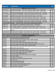
GCF DRIVE ASSEMBLY GCF41-<strong>61</strong>REF# QTY. PART NO. DESCRIPTION1 1 11203025 Gearbox Box TL 311 (9.311.781.00) RL AP 1/1 1 12003006 Gearbox Box TL 311 (9.311.780.00) RL R=1:32 1 11003005 Gear TL 311 R1:3 LP=170 (N. Cross. SH)2 1 11003006 Gear TL 311 R1:3 LP=240 (N. Cross. SH)2 1 11003015 Gear TL 311 R1:3 LP=270 (N. Cross. SH)2 1 11003016 Gear TL 311 R1:3 LP=320 (N. Cross. SH)2 1 11003017 Gear TL 311 R1:3 LP=370 (N. Cross. SH)2 1 11003018 Gear TL 311 R1:3 LP=420 (N. Cross. SH)2 1 11003019 Gear TL 311 R1:3 LP=520 (N. Cross. SH)2 1 11003030 Gear TL 311 A. Pass R1:3 LP=5202 1 15003070 Gear TL 311 R1:3 LP=470 (N. Cross. SH)2 1 15003071 Gear TL 311 R1:3 LP=620 (N. Cross. SH)3 1 15003056 Pulley 3SPB 1404 1 15003054 Taper Lock Viblock VK 156 40 x 80 Std.5 3 12003001 Belt BX436 1 13003005 Taper Lock Viblock VK 156 35 x 807 1 15003055 Pulley 3SPB 180Page 19
GCF DRIVE ASSEMBLY GCF41-<strong>61</strong>REF# QTY. PART NO. DESCRIPTION9 3 96<strong>61</strong>2421 Bolt TE M14 x 040 UNI 5739 8.8 ZN10 1 11003001 Ext. Sh. DA17010 1 11003002 Ext. Sh. DA24010 1 15003018 Ext. Sh. DA27010 1 15003019 Ext. Sh. DA32010 1 15003020 Ext. Sh. DA37010 1 15003021 Ext. Sh. DA42010 1 15003022 Ext. Sh. DA47010 1 15003023 Ext. Sh. DA52010 1 15003024 Ext. Sh. DA62011 1 97093311 Smooth Washer M14 UNI 5714 ZN12 1 96<strong>61</strong>0027 Bolt TE M12 x 035 UNI 5739 8.8 Black13 1 97495034 Washer ELSP ASA B-27-12.2 x 21.2 x 2.5 N14 4 96605321 Bolt TE M08 x 012 UNI 5739 8.8 ZN15 4 97094921 Smooth Washer M8 9 x 24 x 2 ZN16 1 14310012 Circular Protection (30/211)17 4 97495034 Washer ELSP ASA B-27 12.2 x 21.2 x 2.5 N18 4 96609827 Bolt TE M12 x 025 UNI 5739 8.8 Black22 3 97495134 Washer ELSP ASA B-27 14.2 x 24.1 x 3 N23 3 97972321 Low Self Block Nut M14-6S UNI 747424 1 11003014 Plate F.Gearbox 6 mm24 1 13003467 Plate25 1 96<strong>61</strong>0121 Bolt TE M12 x 040 UNI 5739 8.8 ZN26 1 96979971 Nut M12-6SS UNI 5589 BASSO H=0730 1 11003007 CPL. Shaft L=21530 1 11003008 CPL. Shaft L=28530 1 15003026 CPL. Shaft L=31530 1 15003027 CPL. Shaft L=36530 1 15003028 CPL. Shaft L=41530 1 15003029 CPL. Shaft L=46530 1 15003030 CPL. Shaft L=51530 1 15003031 CPL. Shaft L=56530 1 15003032 CPL. Shaft L=66531 1 15003052 Bearing 6208 2RS1 40 x 80 x 1832 1 96867476 El. Ring F.Shafts 40 x 1.7533 1 11003011 CPL Ext. Shaft DA17033 1 11003012 CPL Ext. Shaft DA24033 1 15003008 CPL Ext. Shaft DA27033 1 15003009 CPL Ext. Shaft DA32033 1 15003010 CPL Ext. Shaft DA37033 1 15003011 CPL Ext. Shaft DA42033 1 15003012 CPL Ext. Shaft DA47033 1 15003013 CPL Ext. Shaft DA52033 1 15003014 CPL Ext. Shaft DA620Page 20
GCF DRIVE ASSEMBLY GCF69-79REF# QTY. PART NO. DESCRIPTION1 1 48030942 Gearbox Box TL 311 (9.311.784.00) RL AP R21 1 48030943 Gearbox Box TL 311 (9.311.785.00) RL R=1:23 1 13003012 Pulley 4SPB 1604 1 13003006 Taper Lock Viblock VK156 45 x 804 1 15003054 Taper Lock Viblock VK156 40 x 80 Std.5 1 480307<strong>61</strong> Belt BX496 1 13003005 Taper Lock Viblock VK165 35 x 807 1 75000307 Pulley 4SPB 2509 1 96<strong>61</strong>2421 Bolt TE M14 x 040 UNI 5739 8.8 ZN11 1 96<strong>61</strong>0027 Bolt TE M12 x 035 UNI 5739 8.8 Black12 1 97972321 Low Selfblock Nut M14-6S UNI 747413 1 97495034 Washer ELSP ASA B-27 12.2 x 21.2 x 2.5 N14 1 96605321 Bolt TE M08 x 012 UNI 5739 8.8 ZN15 1 97094921 Smooth Washer M8 9 x 24 x 2 ZN16 1 14310012 Circular Protection (30/211)17 1 97495034 Washer ELSP ASA B-27 12.2 x 21.2 x 2.5 N18 1 96609827 Bolt TE M12 x 025 UNI 5739 8.8 Black20 1 97093311 Smooth Washer M14 UNI 5714 ZNPage 21
GCF GEARBOX ASSEMBLY GCF41-<strong>61</strong>REF# QTY. PART NO. DESCRIPTION1 1 48030292 Plug2 1 48030<strong>61</strong>5 Spl. Shaft F.W. 1" 3/8 Z6 (0.311.3201.00)3 1 10503016 Oil Seal 35 x 80 x 104 1 96607627 Bolt TE M10 x 025 UNI 5739 8.8 Black5 1 96874776 El. Ring F.Holes 80 x 2.56 1 48030984 Spacer 35.3 x 48 x 1 (0.259.7510.00)7 1 75000029 Bearing 6307 A SFERE8 1 48030<strong>61</strong>6 Taper Crown WH.Z 36 M5 (0.311.6200.00)9 1 48030799 Feather For Free Wheel (0.267.7109.00)11 1 48030267 Closing Cap 80 x 10 (8.7.0.00790)12 1 48030003 Cap 3/8" G (8.6.7.001<strong>61</strong>) NPT13 1 48030415 Spacer 48.0 x 35.3 x 0.3 (0.259.7503.00)14 1 48030411 Bearing 32207 A RULLI CON.15 1 48030884 Spacer 69.0 x 79.9 (0.267.7503.00)16 1 36902003 Bearing 6207 35 x 72 x 17 Ball Bearing17 1 48030180 Oil Seal 35 x 72 x 1018 1 48030538 Pinion Shaft Z12 M4.35 (0.304.5015.00)19 1 96864576 El. Ring F.Shafts 35 x 2.520 1 48030991 Gearbox T2 (0.311.0300.00)21 1 48030535 Spacer 48.0 x 35.3 x 1.3 (0.259.7513.00)22 1 48030992 Open Cover Prot. (0.311.1300.00) T223 1 48030982 El. Ring F. Shafts 42 (8.5.1.00712)24 1 48030983 Spring For Free Wheel (0.267.7110.00)Page 23
GCF GEARBOX ASSEMBLY GCF69-79REF# QTY. PART NO. DESCRIPTION1 1 48030<strong>61</strong>5 SPL. Shaft F.W. 1" 3/8 Z6 (0.311.3201.00)2 1 48030811 Oil Seal 40 x 80 x 12 (8.7.1.00748)3 1 48030246 Cap Ext. Hex. 3/8 NPT (8.6.5.00006)4 1 96607627 Bolt TE M10 x 025 UNI 5739 8.8 Black5 1 96874776 El. Ring F.Holes 80 x 2.56 1 75000029 Bearing 6307 A SFERE7 1 48030281 Spacer 35.3 x 48 (0.259.7500.00)8 1 48030984 Spacer 35.3 x 48 x 1 (0.259.7510.00)9 1 48403053 Taper Crown WH.Z 28 M5.35 (0.311.6206.00)R10 1 48030799 Feather For Free Wheel (0.267.7109.00)11 1 48030267 Closing Cap 80 x 10 (8.7.0.00790)12 1 48030884 Spacer 69.0 x 79.9 (0.267.7503.00)13 1 48030983 Spring For Free Wheel (0.267.7110.00)14 1 48030982 El. Ring F.Shafts 42 (8.5.1.00712)15 1 48030411 Bearing 32207 A RULLI CON.16 1 48030003 Cap 3/8" G (8.6.7.001<strong>61</strong>) NPT17 1 36902003 Bearing 6207 35 x 72 x 17 Ball Bearing18 1 48030180 Oil Seal 35 x 72 x 1019 1 48403054 Albero Pinion Z11 M5.35 (0.304.5014.00)20 1 96864576 El. Ring F. Shafts 35 x 2.521 1 48030991 Gearbox T2 (0.311.0300.00)22 1 48030992 Open Cover Protection (0.311.1300.00) T224 1 48030753 Feather A 10 x 8 x 65 (8.4.1.01689)25 1 96693823 Bolt TCEI M12 x 030 UNI 5931 8.8 Black26 1 48030535 Spacer 48.0 x 35.3 x 1.3 (0.259.7513.00)Page 24
GCF41-<strong>61</strong> PTO SHAFTBondioli & PavesiREF# QTY. PART NO. DESCRIPTION1 2 572040351 RS Yoke 1-3/8 6 Spline2 2 41204 #4 Cross Kit3 1 204046851 Outer Tube Yoke4 1 341038000 Roll Pin O.T.5 1 225120860 Outer Drive Tube 860 mm6 1 225100860 Inner Drive Tube 860 mm7 1 204046852 Inner Tube Yoke8 1 341048000 Roll Pin I.T.9 2 240002451 RS Collar Kit10 1 255040005 Shield Bearing Outer11 1 255040006 Shield Bearing Inner12 2 252000001 Safety Chain13 1 5F04086F6 Complete Shield w/Bearings1 7104071UCR07R07 Complete Driveline AssemblyPlease specify <strong>drive</strong>line manufacturer when ordering parts.Page 25
GCF69-79 PTO SHAFTBondioli & PavesiREF# QTY. PART NO. DESCRIPTION1 2 572060351 RS Yoke 1-3/8 6 Spline2 2 41206 #6 Cross Kit3 1 204066851 Outer Tube Yoke4 1 341042000 Roll Pin O.T.5 1 225690860 Outer Drive Tube 860 mm6 1 225110860 Inner Drive Tube 860 mm7 1 204066852 Inner Tube Yoke8 1 341043000 Roll Pin I.T.9 2 240003051 RS Collar Kit10 1 255060005 Shield Bearing Outer11 1 255060006 Shield Bearing Inner12 2 252000001 Safety Chain13 1 5F06086FF Complete Shield w/Bearings1 7106086T07S07 Complete Driveline AssemblyPlease specify <strong>drive</strong>line manufacturer when ordering parts.Page 26
GCF41-<strong>61</strong> PTO SHAFTWeaslerREF# QTY. PART NO. DESCRIPTION1 2 400.421638 Yoke Auto Lock2 2 201-8474 Cross and Bearing Kit3 1 410.400236 Yoke Inner Tube4 2 795.0865 Spring Pin 8 x 655 1 710.364 Inner Tube6 1 710.433 Outer Tube7 1 410.400243 Yoke Outer Tube8 2 9<strong>61</strong>-2543 Bearing Kit9 1 900-2560 Shield Kit1 13006500 Safety Chain Kit (Not Shown)1 ZB4071638 Complete Driveline AssemblyPlease specify <strong>drive</strong>line manufacturer when ordering parts.Page 27
GCF69-79 PTO SHAFTWeaslerREF# QTY. PART NO. DESCRIPTION1 2 110-8606 Yoke Auto Lock2 2 201-8692 Cross and Bearing Kit3 1 410.600245 Yoke Inner Tube4 2 795.1080 Spring Pin 10 x 805 1 710.454 Inner Tube6 1 710.544 Outer Tube7 1 410.600254 Yoke Outer Tube8 2 9<strong>61</strong>-3567 Bearing Kit9 1 902-3560 Shield Kit1 13006500 Safety Chain Kit (Not Shown)1 AB608363 Complete Driveline AssemblyPlease specify <strong>drive</strong>line manufacturer when ordering parts.Page 28
LIMITED WARRANTYGEARMORE, INC., warrants each new <strong>Gearmore</strong> product to be free from defects in materialand workmanship for a period of twelve (12) months from date of purchase to the originalpurchaser. This warranty shall not apply to implements or parts that have been subject tomisuse, negligence, accident, or that have been altered in any way.Our obligation shall be limited to repairing or replacement of any part, provided that suchpart is returned within thirty (30) days from date of failure to <strong>Gearmore</strong> through the dealerfrom whom the purchase was made, transportation charges prepaid.This warranty shall not be interpreted to render us liable for injury or damages of any kind ornature, direct, consequential or contingent, to person or property. This warranty does notextend to loss of crops, loss because of delay in harvesting or any other expenses, for anyother reasons.<strong>Gearmore</strong> in no way warranties engines, tires, or other trade accessories, since these itemsare warranted separately by these respective manufacturers.<strong>Gearmore</strong> reserves the right to make improvements in design or changes in specification atany time, without incurring any obligations to owners or units previously sold.GEARMORE, INC.13477 Benson Ave.Chino, CA 91710Always refer to and heed machine operating warning decals on machine.The serial number of this product is stored in our computer database, thussubmitting a warranty registration card is not required.Page 29