Report-KLIA (Page 1)
Report-KLIA (Page 1)
Report-KLIA (Page 1)

You also want an ePaper? Increase the reach of your titles
YUMPU automatically turns print PDFs into web optimized ePapers that Google loves.
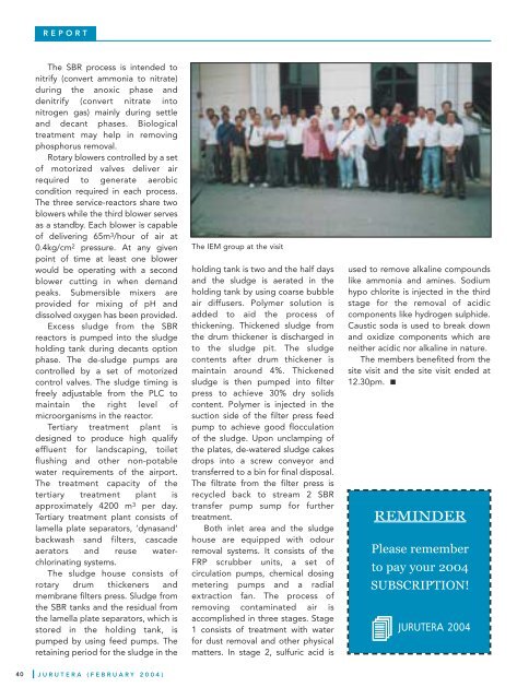
JURUTERA (FEBRUARY 2004)REPORTThe SBR process is intended tonitrify (convert ammonia to nitrate)during the anoxic phase anddenitrify (convert nitrate intonitrogen gas) mainly during settleand decant phases. Biologicaltreatment may help in removingphosphorus removal.Rotary blowers controlled by a setof motorized valves deliver airrequired to generate aerobiccondition required in each process.The three service-reactors share twoblowers while the third blower servesas a standby. Each blower is capableof delivering 65m3/hour of air at0.4kg/cm 2 pressure. At any givenpoint of time at least one blowerwould be operating with a secondblower cutting in when demandpeaks. Submersible mixers areprovided for mixing of pH anddissolved oxygen has been provided.Excess sludge from the SBRreactors is pumped into the sludgeholding tank during decants optionphase. The de-sludge pumps arecontrolled by a set of motorizedcontrol valves. The sludge timing isfreely adjustable from the PLC tomaintain the right level ofmicroorganisms in the reactor.Tertiary treatment plant isdesigned to produce high qualifyeffluent for landscaping, toiletflushing and other non-potablewater requirements of the airport.The treatment capacity of thetertiary treatment plant isapproximately 4200 m 3 per day.Tertiary treatment plant consists oflamella plate separators, ‘dynasand’backwash sand filters, cascadeaerators and reuse waterchlorinatingsystems.The sludge house consists ofrotary drum thickeners andmembrane filters press. Sludge fromthe SBR tanks and the residual fromthe lamella plate separators, which isstored in the holding tank, ispumped by using feed pumps. Theretaining period for the sludge in theThe IEM group at the visitholding tank is two and the half daysand the sludge is aerated in theholding tank by using coarse bubbleair diffusers. Polymer solution isadded to aid the process ofthickening. Thickened sludge fromthe drum thickener is discharged into the sludge pit. The sludgecontents after drum thickener ismaintain around 4%. Thickenedsludge is then pumped into filterpress to achieve 30% dry solidscontent. Polymer is injected in thesuction side of the filter press feedpump to achieve good flocculationof the sludge. Upon unclamping ofthe plates, de-watered sludge cakesdrops into a screw conveyor andtransferred to a bin for final disposal.The filtrate from the filter press isrecycled back to stream 2 SBRtransfer pump sump for furthertreatment.Both inlet area and the sludgehouse are equipped with odourremoval systems. It consists of theFRP scrubber units, a set ofcirculation pumps, chemical dosingmetering pumps and a radialextraction fan. The process ofremoving contaminated air isaccomplished in three stages. Stage1 consists of treatment with waterfor dust removal and other physicalmatters. In stage 2, sulfuric acid isused to remove alkaline compoundslike ammonia and amines. Sodiumhypo chlorite is injected in the thirdstage for the removal of acidiccomponents like hydrogen sulphide.Caustic soda is used to break downand oxidize components which areneither acidic nor alkaline in nature.The members benefited from thesite visit and the site visit ended at12.30pm.REMINDERPlease rememberto pay your 2004SUBSCRIPTION!JURUTERA 200440