Manual (pdf) - Artisan Scientific
Manual (pdf) - Artisan Scientific
Manual (pdf) - Artisan Scientific
- No tags were found...

Create successful ePaper yourself
Turn your PDF publications into a flip-book with our unique Google optimized e-Paper software.
ContentsHP E1343A/44A/45A/47A Relay Multiplexer User’s <strong>Manual</strong>Edition 5Warranty ....................................................................................................................... 5Safety Symbols ............................................................................................................. 6WARNINGS................................................................................................................. 6Declaration of Conformity............................................................................................ 7Reader Comment Sheet ................................................................................................ 9Chapter 1Getting Started ............................................................................................................. 11Using This Chapter ..................................................................................................... 11Multiplexer Module Description ................................................................................ 11General Description ............................................................................................. 11Multiplexer Channel Descriptions and Connections ........................................... 11Programming the Multiplexer Module ....................................................................... 14Selecting Channels .............................................................................................. 14SCPI Command Format Used in This <strong>Manual</strong> .................................................... 16Initial Operation.......................................................................................................... 17Chapter 2Configuring the Relay Multiplexer Modules ............................................................ 19Warnings and Cautions............................................................................................... 19Connecting Field Wiring ............................................................................................ 20Wiring Guidelines ............................................................................................... 20Wiring a Terminal Module ......................................................................................... 21Connecting the Analog Bus ........................................................................................ 22Setting the Card ID ..................................................................................................... 23Setting the Logical Address Switch............................................................................ 23Using the Multiplexer Module with an HP Mainframe or Command Module .......... 24Using the Scanning Voltmeter Configuration ..................................................... 24Using the Switchbox Configuration .................................................................... 25Verifying Correct Logical Address Settings ....................................................... 25Selecting the Interrupt Priority ................................................................................... 265 Volt Excitation for Strain Gages.............................................................................. 27Adding Signal Conditioning Components/Current Shunts......................................... 27Connecting User Inputs .............................................................................................. 29Chapter 3Using the Relay Multiplexer Modules ........................................................................ 31Using This Chapter ..................................................................................................... 31Multiplexer Commands .............................................................................................. 31Connecting Switchbox Channels to Common............................................................ 32Connecting Switchbox Channels to Tree Terminals for Making Measurements....... 34Scanning a Range of Switchbox Channels ................................................................. 36Measuring Temperature Using Thermocouples(HP E1344A/47A Modules Only)............................................................................ 39Contents 1<strong>Artisan</strong> Technology Group - Quality Instrumentation ... Guaranteed | (888) 88-SOURCE | www.artisantg.com
[:IMMediate] ....................................................................................................... 68:SOURce .............................................................................................................. 69:SOURce? ............................................................................................................ 70IEEE 488.2 Common Commands............................................................................... 71Command Quick Reference........................................................................................ 72Appendix A16-Channel Relay Multiplexer Specifications ........................................................... 73HP E1343A/44A 16-Channel Relay Multiplexer ....................................................... 73HP E1345A/47A 16-Channel Relay Multiplexer ....................................................... 74Relay Life ................................................................................................................... 75End of Life Detection ................................................................................................. 75Replacement Strategy ................................................................................................. 75Appendix B16-Channel Relay Multiplexer Registers ................................................................... 77Register Addressing ............................................................................................ 77Computer Configurations .................................................................................... 78Reading the Registers .......................................................................................... 81Writing to the Registers ....................................................................................... 82Register Definitions ............................................................................................. 83Appendix C16-Channel Relay Multiplexer Error Messages ........................................................ 85Index ................................................................................................................................ 87Contents 3<strong>Artisan</strong> Technology Group - Quality Instrumentation ... Guaranteed | (888) 88-SOURCE | www.artisantg.com
4 Contents<strong>Artisan</strong> Technology Group - Quality Instrumentation ... Guaranteed | (888) 88-SOURCE | www.artisantg.com
CertificationHewlett-Packard Company certifies that this product met its published specifications at the time of shipment from the factory. Hewlett-Packard further certifies that its calibration measurements are traceable to the United States National Institute of Standards andTechnology (formerly National Bureau of Standards), to the extent allowed by that organization’s calibration facility, and to thecalibration facilities of other International Standards Organization members.WarrantyThis Hewlett-Packard product is warranted against defects in materials and workmanship for a period of three years from date of shipment.Duration and conditions of warranty for this product may be superseded when the product is integrated into (becomes a part of) other HPproducts. During the warranty period, Hewlett-Packard Company will, at its option, either repair or replace products which prove to bedefective.For warranty service or repair, this product must be returned to a service facility designated by Hewlett-Packard (HP). Buyer shall prepayshipping charges to HP and HP shall pay shipping charges to return the product to Buyer. However, Buyer shall pay all shipping charges,duties, and taxes for products returned to HP from another countryHP warrants that its software and firmware designated by HP for use with a product will execute its programming instructions whenproperly installed on that product. HP does not warrant that the operation of the product, or software, or firmware will be uninterruptedor error free.Limitation Of WarrantyThe foregoing warranty shall not apply to defects resulting from improper or inadequate maintenance by Buyer, Buyer-supplied pr oductsor interfacing, unauthorized modification or misuse, operation outside of the environmental specifications for the product, or impropersite preparation or maintenance.The design and implementation of any circuit on this product is the sole responsibility of the Buyer. HP does not warrant the Buyer’scircuitry or malfunctions of HP products that result from the Buyer’s circuitry. In addition, HP does not warrant any damage that occursas a result of the Buyer’s circuit or any defects that result from Buyer-supplied products.NO OTHER WARRANTY IS EXPRESSED OR IMPLIED. HP SPECIFICALLY DISCLAIMS THE IMPLIED WARRANTIES OFMERCHANTABILITY AND FITNESS FOR A PARTICULAR PURPOSE.Exclusive RemediesTHE REMEDIES PROVIDED HEREIN ARE BUYER’S SOLE AND EXCLUSIVE REMEDIES. HP SHALL NOT BE LIABLE FORANY DIRECT, INDIRECT, SPECIAL, INCIDENTAL, OR CONSEQUENTIAL DAMAGES, WHETHER BASED ON CONTRACT,TORT, OR ANY OTHER LEGAL THEORY.NoticeThe information contained in this document is subject to change without notice. HEWLETT-PACKARD (HP) MAKES NOWARRANTY OF ANY KIND WITH REGARD TO THIS MATERIAL, INCLUDING, BUT NOT LIMITED TO, THE IMPLIEDWARRANTIES OF MERCHANTABILITY AND FITNESS FOR A PARTICULAR PURPOSE. HP shall not be liable for errorscontained herein or for incidental or consequential damages in connection with the furnishing, performance or use of this material. Thisdocument contains proprietary information which is protected by copyright. All rights are reserved. No part of this document may bephotocopied, reproduced, or translated to another language without the prior written consent of Hewlett-Packard Company. HP assumesno responsibility for the use or reliability of its software on equipment that is not furnished by HP.U.S. Government Restricted RightsThe Software and Documentation have been developed entirely at private expense. They are delivered and licensed as "commercialcomputer software" as defined in DFARS 252.227- 7013 (Oct 1988), DFARS 252.211-7015 (May 1991) or DFARS 252.227-7014 (Jun1995), as a "commercial item" as defined in FAR 2.101(a), or as "Restricted computer software" as defined in FAR 52.227-19 (Jun1987)(or any equivalent agency regulation or contract clause), whichever is applicable. You have only those rights provided for suchSoftware and Documentation by the applicable FAR or DFARS clause or the HP standard software agreement for the product involvedHP E1343A/44A/45A/47A User’s <strong>Manual</strong>Edition 5Copyright © 1997 Hewlett-Packard Company. All Rights Reserved.5<strong>Artisan</strong> Technology Group - Quality Instrumentation ... Guaranteed | (888) 88-SOURCE | www.artisantg.com
Documentation HistoryAll Editions and Updates of this manual and their creation date are listed below. The first Edition of the manual is Edition 1. The Editionnumber increments by 1 whenever the manual is revised. Updates, which are issued between Editions, contain replacement pages tocorrect or add additional information to the current Edition of the manual. Whenever a new Edition is created, it will contain all of theUpdate information for the previous Edition. Each new Edition or Update also includes a revised copy of this documentation history page.Edition 1 . . . . . . . . . . . . . . . . . . . . . . . . . . . . . . . . . . . . . . . . . . .September 1989Update 1. . . . . . . . . . . . . . . . . . . . . . . . . . . . . . . . . . . . . . . . . . . .September 1990Edition 2 . . . . . . . . . . . . . . . . . . . . . . . . . . . . . . . . . . . . . . . . . . . . . . . . July 1992Edition 3 . . . . . . . . . . . . . . . . . . . . . . . . . . . . . . . . . . . . . . . . . . . . . . . April 1993Edition 4 . . . . . . . . . . . . . . . . . . . . . . . . . . . . . . . . . . . . . . . . . . . . . . . .May 1995Edition 5 . . . . . . . . . . . . . . . . . . . . . . . . . . . . . . . . . . . . . . . . . . . . . . . April 1997Safety SymbolsInstruction manual symbol affixed toproduct. Indicates that the user must refer tothe manual for specific WARNING orCAUTION information to avoid personalinjury or damage to the product.Alternating current (AC)Direct current (DC).Indicates the field wiring terminal that mustbe connected to earth ground beforeoperating the equipment—protects againstelectrical shock in case of fault.WARNINGIndicates hazardous voltages.Calls attention to a procedure, practice, orcondition that could cause bodily injury ordeath.orFrame or chassis ground terminal—typicallyconnects to the equipment's metal frame.CAUTIONCalls attention to a procedure, practice, orcondition that could possibly cause damage toequipment or permanent loss of data.WARNINGSThe following general safety precautions must be observed during all phases of operation, service, and repair of this product. Failure tocomply with these precautions or with specific warnings elsewhere in this manual violates safety standards of design, manufacture, andintended use of the product. Hewlett-Packard Company assumes no liability for the customer's failure to comply with these requirements.Ground the equipment: For Safety Class 1 equipment (equipment having a protective earth terminal), an uninterruptible safety earthground must be provided from the mains power source to the product input wiring terminals or supplied power cable.DO NOT operate the product in an explosive atmosphere or in the presence of flammable gases or fumes.For continued protection against fire, replace the line fuse(s) only with fuse(s) of the same voltage and current rating and type. DO NOTuse repaired fuses or short-circuited fuse holders.Keep away from live circuits: Operating personnel must not remove equipment covers or shields. Procedures involving the removal ofcovers or shields are for use by service-trained personnel only. Under certain conditions, dangerous voltages may exist even with theequipment switched off. To avoid dangerous electrical shock, DO NOT perform procedures involving cover or shield removal unless youare qualified to do so.DO NOT operate damaged equipment: Whenever it is possible that the safety protection features built into this product have beenimpaired, either through physical damage, excessive moisture, or any other reason, REMOVE POWER and do not use the product untilsafe operation can be verified by service-trained personnel. If necessary, return the product to a Hewlett-Packard Sales and Service Officefor service and repair to ensure that safety features are maintained.DO NOT service or adjust alone: Do not attempt internal service or adjustment unless another person, capable of rendering first aid andresuscitation, is present.DO NOT substitute parts or modify equipment: Because of the danger of introducing additional hazards, do not install substitute partsor perform any unauthorized modification to the product. Return the product to a Hewlett-Packard Sales and Service Office for serviceand repair to ensure that safety features are maintained.6<strong>Artisan</strong> Technology Group - Quality Instrumentation ... Guaranteed | (888) 88-SOURCE | www.artisantg.com
Declaration of Conformityaccording to ISO/IEC Guide 22 and EN 45014Manufacturer’s Name:Manufacturer’s Address:Hewlett-Packard CompanyLoveland Manufacturing Center815 14th Street S.W.Loveland, Colorado 80537declares, that the product:Product Name:Model Number:Product Options:16-Channel Relay Multiplexer ModulesHP E1343A/44A/45A/47AAllconforms to the following Product Specifications:Safety: IEC 348:1978/HD 401 S1:1981CSA 556BUL 1244EMC:CISPR 11:1990/EN55011 (1991): Group 1 Class AEN50082-1:1992IEC 801-2:1991: 4kVCD, 8kVADIEC 801-3:1984: 3 V/mIEC 801-4:1988: 1kV Power Line, 0.5kV Signal LinesSupplementary Information: The product herewith complies with the requirements of the Low Voltage Directive73/23/EEC and the EMC Directive 89/336/EEC (inclusive 89/336/EEC) and carries the "CE" marking accordingly.Tested in a typical configuration in an HP B-Size VXI mainframe.Safety qualification performed May, 1989.September 5, 1996Jim White, QA ManagerEuropean contact: Your local Hewlett-Packard Sales and Service Office or Hewlett-Packard GmbH, DepartmentHQ-TRE, Herrenberger Straße 130, D-71034 Böblingen, Germany (FAX +49-7031-14-3143)7<strong>Artisan</strong> Technology Group - Quality Instrumentation ... Guaranteed | (888) 88-SOURCE | www.artisantg.com
Notes:8<strong>Artisan</strong> Technology Group - Quality Instrumentation ... Guaranteed | (888) 88-SOURCE | www.artisantg.com
Please fold and tape for mailingReader Comment SheetHP E1343A/44A/45A/47A User’s <strong>Manual</strong>Edition 5You can help us improve our manuals by sharing your comments and suggestions. In appreciation of your time, we willenter you in a quarterly drawing for a Hewlett-Packard Palmtop Personal Computer (U.S. government employeesare not eligible for the drawing).Your NameCompany NameJob TitleCity, State/ProvinceCountryZip/Postal CodeAddressTelephone Number with Area CodePlease list the system controller, operating system, programming language, and plug-in modules you are using.fold herecut along this lineBUSINESS REPLY MAILFIRST CLASS PERMIT NO. 37 LOVELAND, COPOSTAGE WILL BE PAID BY ADDRESSEEHEWLETT-PACKARD COMPANYMeasurement Systems DivisionLearning Products DepartmentP.O. Box 301Loveland, CO 80539-9984NO POSTAGENECESSARYIF MAILEDIN THEUNITED STATESfold herePlease pencil-in one circle for each statement below: Disagree Agree• The documentation is well organized. O O O O O• Instructions are easy to understand. O O O O O• The documentation is clearly written. O O O O O• Examples are clear and useful. O O O O O• Illustrations are clear and helpful. O O O O O• The documentation meets my overall expectations. O O O O OPlease write any comments or suggestions below–be specific.<strong>Artisan</strong> Technology Group - Quality Instrumentation ... Guaranteed | (888) 88-SOURCE | www.artisantg.com
<strong>Artisan</strong> Technology Group - Quality Instrumentation ... Guaranteed | (888) 88-SOURCE | www.artisantg.com
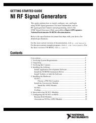
Chapter 1Getting StartedUsing This ChapterMultiplexer Module DescriptionThis chapter describes the HP E1343A 16-Channel High Voltage Relay,E1344A 16-Channel General Purpose Thermocouple High Voltage Relay,E1345A 16-Channel Relay, and HP E1347A 16-Channel ThermocoupleRelay Multiplexer Modules, and shows how to program the modules usingSCPI commands (Standard Commands for Programmable Instruments).This chapter contains the following sections:• Multiplexer Module Description. . . . . . . . . . . . . . . . . . . . . . page 11• Programming the Multiplexer Module . . . . . . . . . . . . . . . . . page 14• Initial Operation . . . . . . . . . . . . . . . . . . . . . . . . . . . . . . . . . . page 17Refer to Figure 1-1 for the following explanations of all four 16-ChannelRelay Multiplexer Modules.General DescriptionThe multiplexer module switches (multiplexes) up to 16 channels. Eachchannel provides High (H), Low (L), and Guard (G) connections.The multiplexer module consists of a component assembly and a terminalmodule. The channel relay switches are on the component assembly. Thefield wiring from user sources (e.g., thermocouples) connects to the terminalmodule. The terminal module also provides connections for multimeters,voltmeters, counters, and other measuring devices.MultiplexerChannelDescriptions andConnectionsThe channel relay switches are separated into two banks, Bank 0 andBank 1. Channels 00 to 07 are in Bank 0 and channels 08 to 15 are inBank 1. Each bank has its own H, L, and G Common terminals to which thechannel switches connect.The channel switches also connect, through the AT and BT Tree Switches,to the AT and BT Tree Switch Terminals, respectively. The Bank 0 channelsconnect to the AT Tree Switch Terminals and the Bank 1 channels connectto the BT Tree Switch Terminals. An additional tree switch, the AT2 TreeSwitch, provides connection of the Bank 1 channels to AT Tree SwitchTerminals. Use channel numbers 90, 91, and 92 to select the AT, BT, andAT2 Tree Switches, respectively.Connecting to the Tree Switch Terminals is the preferred method to connectmeasuring devices, like multimeters, to measure the multiplexer channels.This allows you to connect the measuring device to either the Bank 0 orBank 1 channels at any given time, or to the channels of both banks.Chapter 1Getting Started 11<strong>Artisan</strong> Technology Group - Quality Instrumentation ... Guaranteed | (888) 88-SOURCE | www.artisantg.com
The AT Tree Switch Terminals also connect to the H, L, and G connectionson the Analog Bus Connector. The BT Tree Switch Terminals also connectto the I+, I-, and IG connections on the Analog Bus Connector. The AnalogBus Connector provides direct channel connections between multiplemultiplexer modules, and connections between a multiplexer module andthe HP E1326/E1411 Multimeters. Cables make the necessary connectionswithout the need to externally wire the multimeter/multiplexer modules viathe terminal modules.The 16-Channel Thermocouple Relay Multiplexer Modules (HP E1344Aand E1347A) uses the RT Tree Switch (Channel 93) to connect thethermistor on the terminal module to the Bank 1 channel common. Thethermistor can be measured to determine the temperature inside of theterminal module to compensate for temperature measurements made withthermocouples (see Chapter 3).Each channel High (H) line has a jumper on the terminal module that maybe removed to add filter components (see Chapter 2 under the “AddingSignal Conditioning Components/Current Shunts” heading). Each Bank 0and Bank 1 common line, the AT and BT Tree Switch, and the Analog Buslines all have 100 ohm resistors in series with each line. The resistorsprovide relay protection and are located on the component module.12 Getting Started Chapter 1<strong>Artisan</strong> Technology Group - Quality Instrumentation ... Guaranteed | (888) 88-SOURCE | www.artisantg.com
Figure 1-1. Multiplexer Module Block DiagramChapter 1Getting Started 13<strong>Artisan</strong> Technology Group - Quality Instrumentation ... Guaranteed | (888) 88-SOURCE | www.artisantg.com
Programming the Multiplexer ModuleThe multiplexer modules are programmed either in a switchbox or scanningvoltmeter configuration. To program the multiplexer modules using theStandard Commands for Programmable Instruments (SCPI), you must selectthe controller language, interface address, and SCPI commands to be used.See the HP 75000 Series B Installation and Getting Started Guide or theHP E1406 Command Module <strong>Manual</strong> for interface addressing andcontroller language information of multiplexer modules in a switchbox orscanning voltmeter configuration. If using the HP E1300 Mainframe orHP E1405 Command Module, you MUST have version 06.00 (orgreater) firmware for the Multiplexer Modules to properly identify.NoteThis discussion applies to SCPI programming. See Appendix B(“16-Channel Relay Multiplexer Registers”) for details on multiplexermodules registers.Selecting ChannelsTo address specific channels within a multiplexer module in a switchbox orscanning voltmeter configuration, you must:• send the appropriate SCPI command string to the switchbox orscanning voltmeter (e.g., CLOSe, OPEN, etc.)• specify the card number• specify the channel numberMultiplexer CardNumbersThe card number identifies the module within a switchbox or scanningvoltmeter configuration. The switch module with the lowest logical addressis always card number 01. The card number with the next successive logicaladdress is 02, and so on. Figure 1-2 illustrates the card number and logicaladdress of a typical single module switchbox.Figure 1-2. Card Numbers for a Single Module Switchbox14 Getting Started Chapter 1<strong>Artisan</strong> Technology Group - Quality Instrumentation ... Guaranteed | (888) 88-SOURCE | www.artisantg.com
Figure 1-3 illustrates the card numbers and logical addresses of a typicalmultiple module switchbox. Figure 1-4 illustrates the card numbers of atypical multiple module scanning voltmeter.Figure 1-3. Card Numbers for a Multiple Module SwitchboxThe logical addresses noted in Figures 1-2, 1-3, and 1-4 apply to modulesinstalled in an HP 75000 Series B Mainframe (HP Model NumberE1300/E1301) or in a mainframe with an HP E1405/E1406 CommandModule. See the HP 75000 Series B Installation and Getting Started Guideor the HP E1406 Command Module <strong>Manual</strong> for more information onswitchboxes and scanning voltmeter configurations, and logical addressing.If using the HP E1300 Mainframe or HP E1405 Command Module, youMUST have version 06.00 (or greater) firmware for the 16-ChannelMultiplexer Modules to properly identify. For uses in other systems ormainframes, see the appropriate manuals.Figure 1-4. Card Numbers for a Multiple Module Scanning VoltmeterChapter 1Getting Started 15<strong>Artisan</strong> Technology Group - Quality Instrumentation ... Guaranteed | (888) 88-SOURCE | www.artisantg.com
Multiplexer ChannelAddressFor the 16-Channel Multiplexers, the channel address (channel_list) is in theform:n (@ccnn) for a single channel;n (@ccnn,ccnn) for multiple channels;n (@ccnn:ccnn) for sequential channels;n (@ccnn:ccnn,ccnn:ccnn) for groups of sequential channels;n or any combination of the above.where "cc" is the card number and "nn" is the channel number.For example, the command string to close channel 02 of card number 1 is:CLOSe (@0102)Since "cc" (the card number) must be sent, it becomes part of the channelnumber. Also, you can ignore leading zeros in the card numbers. Thus, toclose channel 02, send "102" instead of "0102". To close the above channel,execute:CLOSe (@102)SCPI CommandFormat Used in This<strong>Manual</strong>You can send SCPI commands in either a short or long form. A long formexample is:CLOSe (@102)The same command shown without the lower case letters is the short form.The command then becomes:CLOS (@102)Some commands in this manual are shown with brackets ([ ]). These areimplied or optional commands that you do not have to execute. For example,the ROUT command is an implied command and is shown in this manual as:[ROUT:]CLOS (@102)Thus, to execute these commands, simply enter:CLOS (@102)See Chapter 5 for more explanation about SCPI commands and how to sendthem.16 Getting Started Chapter 1<strong>Artisan</strong> Technology Group - Quality Instrumentation ... Guaranteed | (888) 88-SOURCE | www.artisantg.com
Initial OperationUse the following program example to verify initial multiplexer operationby closing a channel and querying channel closure. The example first resetsthe switchbox and then closes channel 02 of a single multiplexer module(card number 1) in the switchbox. The program next queries the channelclosure state. A returned "1" shows that the command to close the channelhas been sent to the switchbox. A returned "0" shows that the command toclose the channel has not been sent to the switchbox.The computer used in the example is an HP Series 200/300 computer withHP BASIC as the program language. The computer interfaces to themainframe using the Hewlett-Packard Interface Bus (HP-IB) 1 . The HP-IBinterface select code is 7, the HP-IB primary address is 09, and the HP-IBsecondary address is 14. Refer to the HP 75000 Series B Installation andGetting Started Guide for addressing information.Example: Reset the switchbox and close channel 0210 OUTPUT 70914;"*RST" Opens all channels.20 OUTPUT 70914;"CLOS (@102)" Close channel 02.30 OUTPUT 70914;"CLOS? (@102)" Query channel 02 state.40 ENTER 70914;Value Enter results into Value.50 PRINT Value Display result.60 END1. HP-IB is Hewlett-Packard’s implementation of IEEE Std 488.1-1984Chapter 1Getting Started 17<strong>Artisan</strong> Technology Group - Quality Instrumentation ... Guaranteed | (888) 88-SOURCE | www.artisantg.com
Notes:18 Getting Started Chapter 1<strong>Artisan</strong> Technology Group - Quality Instrumentation ... Guaranteed | (888) 88-SOURCE | www.artisantg.com
Chapter 2Configuring the Relay Multiplexer ModulesWarnings and CautionsThis chapter shows how to connect external wiring to the 16-Channel RelayMultiplexer Modules, and how to configure them:• Warnings and Cautions . . . . . . . . . . . . . . . . . . . . . . . . . . . . . page 19• Connecting Field Wiring. . . . . . . . . . . . . . . . . . . . . . . . . . . . page 20• Wiring a Terminal Module . . . . . . . . . . . . . . . . . . . . . . . . . . page 21• Connecting the Analog Bus . . . . . . . . . . . . . . . . . . . . . . . . . page 22• Setting the Card ID . . . . . . . . . . . . . . . . . . . . . . . . . . . . . . . . page 23• Setting the Logical Address Switch . . . . . . . . . . . . . . . . . . . page 23• Using the Multiplexer Module with an HP Mainframe or CommandModule . . . . . . . . . . . . . . . . . . . . . . . . . . . . . . . . . . . . . . . . . page 24• Selecting the Interrupt Priority . . . . . . . . . . . . . . . . . . . . . . . page 26• 5 Volt Excitation for Strain Gages . . . . . . . . . . . . . . . . . . . . page 27• Adding Signal Conditioning Components/Current Shunts. . page 27• Connecting User Inputs. . . . . . . . . . . . . . . . . . . . . . . . . . . . . page 29WARNINGSHOCK HAZARD. Only service-trained personnel who are aware ofthe hazards involved should install, remove, or configure themodules. Before installing any module, disconnect AC power from themainframe and from user wiring.To prevent electrical shock, all wires to the channel connections mustbe insulated to at least 120 Vrms (170 V peak).CautionMAXIMUM VOLTAGE/CURRENT. Maximum voltage that may beapplied between High (H), Low (L), and Guard (G) terminals is 170 Vdc or 120 V rms (170 V peak) for the E1345A/47A or 250 V dc or ACRMS (354 V peak) for the E1343A/44A. Maximum current is 50mA(non-conductive) per channel.STATIC ELECTRICITY. Static electricity is a major cause ofcomponent failure. To prevent damage to the electrical components inthe multiplexer module, observe anti-static techniques wheneverremoving a module from the mainframe or whenever working on amodule.Chapter 2Configuring the Relay Multiplexer Modules 19<strong>Artisan</strong> Technology Group - Quality Instrumentation ... Guaranteed | (888) 88-SOURCE | www.artisantg.com
Connecting Field WiringFigure 2-1 shows the terminal module for the 16-Channel High VoltageRelay (HP E1343A), 16-Channel Relay (HP E1345A), 16-Channel GeneralPurpose Thermocouple High Voltage Relay (HP E1344A), and 16-ChannelThermocouple Relay Multiplexer Modules (HP E1347A). Use the followingguidelines for wire connections.Wiring Guidelines• If possible, use shielded cables with the shields connected to the Guard(G) terminals and to the low connection near the measurement point.• Be sure the wires make good connections on the screw terminals.• For thermocouples, connect the Guard terminal to the thermocouple’sshield lead and the low connection near the measurement point.Figure 2-1. Multiplexer Modules Connector Blocks20 Configuring the Relay Multiplexer Modules Chapter 2<strong>Artisan</strong> Technology Group - Quality Instrumentation ... Guaranteed | (888) 88-SOURCE | www.artisantg.com
Wiring a Terminal ModuleChapter 2Configuring the Relay Multiplexer Modules 21<strong>Artisan</strong> Technology Group - Quality Instrumentation ... Guaranteed | (888) 88-SOURCE | www.artisantg.com
Connecting the Analog BusFigure 2-2 shows how to connect the analog bus between multiplemultiplexer modules and to the HP E1326 Multimeter. Use the cablesshipped with the multiplexer modules to connect the analog bus of themultiplexer modules. Use the cable shipped with the HP E1326 Multimeterto connect the analog bus of the multiplexer module to the Multimeter input.These cables are needed to connect the MUX when mounted in the E1403Module Carrier to the E1411A/B DMM in a C-size cardcage. They must beordered separately.1. Connecting E1411 to RELAY MUXs: use E1326-61611(long analog bus cable).2. Connecting RELAY to RELAY or RELAY to FET MUX:use E1400-61605.Figure 2-2. Analog Bus Connections Between Multiplexer/Multimeter Modules22 Configuring the Relay Multiplexer Modules Chapter 2<strong>Artisan</strong> Technology Group - Quality Instrumentation ... Guaranteed | (888) 88-SOURCE | www.artisantg.com
Setting the Card IDThe Card ID Jumpers indicate which terminal assembly is used. Since theHP E1343-66201 and E1345-66201 assembly is used with a variety ofterminal modules, the ID jumpers may be changed. To reduce setup time andavoid configuration errors, check the jumpers to make sure they match theterminal module used.When the relay multiplexers are shipped from the factory, the Card IDJumpers are set according to the terminal module (E1343/44/45/47/55/56)shipped with them. The system is able to identify the multiplexer with orwithout the terminal module attached.NoteIf the jumper setting does not match the terminal module attached, thesystem will identify the card based on the jumper setting.Setting the Logical Address SwitchThe address switch (LADDR) factory setting is 112. You may have changedthe setting during module installation. Valid address values are from 0 to255. Refer to the HP 75000 Series B System Installation and Getting StartedGuide or the HP E1406 Command Module <strong>Manual</strong> for addressinginformation. Otherwise, to change the setting, refer to the Figure 2-3.Figure 2-3. Locate and Set the Logical Address SwitchChapter 2Configuring the Relay Multiplexer Modules 23<strong>Artisan</strong> Technology Group - Quality Instrumentation ... Guaranteed | (888) 88-SOURCE | www.artisantg.com
Using the Multiplexer Module with an HP Mainframe orCommand ModuleTo program the multiplexer modules with an HP E1300A/01A Mainframeor an HP E1405B/E1406A Command Module, the modules must beconfigured as an instrument. If using the HP E1300 Mainframe orHP E1405 Command Module, you MUST have version 06.00(or greater) firmware for the 16-Channel Multiplexer Modules toproperly identify. An instrument configuration for the multiplexermodules must be a:• Scanning Voltmeter - Used with an HP E1326B/E1411A Multimeter.• Switchbox - Used with other switch type modules, like othermultiplexer modules, etc.(The above requirements are not necessary if using register-basedprogramming to program the modules.)Using the ScanningVoltmeterConfigurationUse this configuration for:1. Easiest system programming.2. Fastest execution speed.3. Thermocouple measurements if using the HP E1326B/E1411Btemperature function.To use this configuration, set the multimeter’s logical address to a multipleof 8. Also set the first multiplexer module’s logical address to the nextaddress value, the second module to the next address value, and so on. Thefollowing shows the logical address settings of a Scanning Voltmeter withthe multimeter address set to 24.Logical Address Module Channels24 HP E1326B/E1411A N/A25 HP E1345A/E1347A 100-11526 HP E1345A/E1347A 200-215To program the scanning voltmeter, use the programming information in theappropriate multimeter manual.24 Configuring the Relay Multiplexer Modules Chapter 2<strong>Artisan</strong> Technology Group - Quality Instrumentation ... Guaranteed | (888) 88-SOURCE | www.artisantg.com
Using theSwitchboxConfigurationUse this configuration when:1. Simultaneously closing multiple channels on multiple modules.2. Other multimeters/modules cannot control the multiplexer modules.To use this configuration, set the first multiplexer module’s logical addressto a multiple of 8. Set the next multiplexer module’s logical address to thenext address value, the third module to the next address value, and so on.The following shows the logical address settings of a switchbox with thefirst multiplexer module address set to 112.Logical Address Module Channels112 HP E1345A/E1347A 100-115113 HP E1345A/E1347A 200-215114 HP E1345A/E1347A 300-315To program the switchbox, use the programming information in this manual.Verifying CorrectLogical AddressSettingsTo verify that the modules have the correct logical address setting, query theHP E1300A/E1301A Mainframe or HP E1405B/E1406A CommandModule as follows:HP E1301A Mainframe - From the “Select a Instrument” prompt of thefront panel, select the following menus:SYSTEMCONFIG?LADDSHP E1300A Mainframe, HP E1405B, or HP E1406A Command Modulewith an RS-232 Terminal - From the “Select an Instrument” prompt, selectthe following menus:SYSTEMCONFIG?LADDSIf no front panel or RS-232 terminal is available, send the following SCPIquery command to the mainframe/command module:VXI:CONF:DLAD?The returning string contains all logical addresses in the system.Chapter 2Configuring the Relay Multiplexer Modules 25<strong>Artisan</strong> Technology Group - Quality Instrumentation ... Guaranteed | (888) 88-SOURCE | www.artisantg.com
Selecting the Interrupt PriorityThe multiplexer modules generate interrupts after a channel relay closing oropening completes. These interrupts set the selected line on the VXIperipheral interrupt bus true.The VXI peripheral interrupt bus consists of 7 interrupt priority lines thatcarry the interrupt signal to the commander. Line 1 has the highest priorityand line 7 the lowest. The multiplexer module’s default setting is line 1, sinceit is the most commonly used interrupt line.The HP E1300A/E1301A Mainframe default operation is to monitor allseven interrupt lines. The HP E1405B/E1406A Command Module’s defaultoperation is to manage only one line. The Command Module does, however,use an interrupt line allocation table that allows you to select which lines thecommand module is to monitor. For embedded controllers, refer to theappropriate controller documentation to determine which of the line(s) thecontroller monitors.When using an HP E1300A/E1301A Mainframe or HP E1405B/E1406ACommand Module for register-based programming (instead of the SCPIdriver) and where the program generates an interrupt, be sure to use themultiplexer module’s interrupt line that does not interfere with the program.Use the line that is not used by the SCPI driver to generate interrupts.Refer to Figure 2-4 to change the interrupt priority. Unsolder and removetwo jumpers from the old priority location. Install the jumpers in the newpriority location (Figure 2-4 shows a priority change from 1 to 7).Figure 2-4. Changing the Priority Interrupt Level Jumpers26 Configuring the Relay Multiplexer Modules Chapter 2<strong>Artisan</strong> Technology Group - Quality Instrumentation ... Guaranteed | (888) 88-SOURCE | www.artisantg.com
5 Volt Excitation for Strain GagesThe E1345-66201 is used with a variety of terminal modules including theE1355A and E1356A Strain Gage Multiplexers. When used with these straingages, the jumpers JM1 and JM2 may be installed to provide 5 voltexcitation to the strain gage bridge. This voltage is fused at 4A. Channel x93is used to sense it.Jumpers JM1 and JM2 must be removed when used with the E1347AThermocouple terminal module. This must be done because the connectorpins in this case are used to sense the 5k Ohm thermistor on the terminalmodule.When the relay multiplexer is shipped from the factory, the jumpers are notinstalled.Adding Signal Conditioning Components/Current ShuntsThe multiplexer module’s terminal module allows you to add components oneach channel for:-- Low-Pass Filters-- Attenuators-- Current Shunts (for current measurements using a voltmeter)Figure 2-5 shows how to install the appropriate components for the aboveconfigurations. In the figure, channel 12 shows a low pass filterconfiguration, channel 07 an attenuator configuration, and channel 04 acurrent shunt configuration.Chapter 2Configuring the Relay Multiplexer Modules 27<strong>Artisan</strong> Technology Group - Quality Instrumentation ... Guaranteed | (888) 88-SOURCE | www.artisantg.com
Figure 2-5. Signal Conditioning Components/Current Shunts28 Configuring the Relay Multiplexer Modules Chapter 2<strong>Artisan</strong> Technology Group - Quality Instrumentation ... Guaranteed | (888) 88-SOURCE | www.artisantg.com
Connecting User InputsThe relay switch modules consist of a relay component module and aconnector (terminal) block. If you choose not to use the supplied connectorblock, Figure 2-6 shows the front panel for the modules and the connectiondiagram for wiring your own terminal connector.Figure 2-6. Relay Multiplexer Modules Front Panel and Connector PinoutChapter 2Configuring the Relay Multiplexer Modules 29<strong>Artisan</strong> Technology Group - Quality Instrumentation ... Guaranteed | (888) 88-SOURCE | www.artisantg.com
Notes:30 Configuring the Relay Multiplexer Modules Chapter 2<strong>Artisan</strong> Technology Group - Quality Instrumentation ... Guaranteed | (888) 88-SOURCE | www.artisantg.com
Chapter 3Using the Relay Multiplexer ModulesUsing This ChapterMultiplexer CommandsThis chapter uses typical examples to show how to use the 16-Channel Relayand 16-Channel Thermocouple Relay Multiplexer Modules. Refer toChapter 4 (“Understanding the Relay Multiplexer Modules”) for moreinformation. This chapter contains the following sections:• Multiplexer Commands. . . . . . . . . . . . . . . . . . . . . . . . . . . . . page 31• Connecting Switchbox Channels to Common . . . . . . . . . . . page 32• Connecting Switchbox Channels to Tree Terminals for MakingMeasurements . . . . . . . . . . . . . . . . . . . . . . . . . . . . . . . . . . . . page 34• Scanning a Range of Switchbox Channels . . . . . . . . . . . . . . page 36• Measuring Temperature Using Thermocouples (HP E1344A/47AModules Only) . . . . . . . . . . . . . . . . . . . . . . . . . . . . . . . . . . . page 39Table 3-1. Multiplexer Commands in Chapter 3CommandARM:COUN INIT[:IMM]INIT:CONT 1|0|ON|OFF[ROUT:]CLOS [ROUT:]CLOS? [ROUT:]OPEN [ROUT:]SCAN [ROUT:]SCAN:MODE FRES[ROUT:]SCAN:PORT ABUSDescriptionSelects multiple scanning cycles.Starts scanning process; use the [ROUT:]SCAN commandto select channels for scanning.Enables/disables continuous scanning cycles.Closes all channels in channel list.Queries mainframe for channel closure.Opens all channels in channel list.Closes all channels in channel list one at a time; previouschannel opens before next channel closes.Automatically closes paired channel relays (e.g., channels01 and 09) during 4-wire ohms measurements andscanning.Automatically closes the tree switches while scanning.NOTE: The commands with brackets ([ ]) are implied and are not shown in this chapterChapter 3Using the Relay Multiplexer Modules 31<strong>Artisan</strong> Technology Group - Quality Instrumentation ... Guaranteed | (888) 88-SOURCE | www.artisantg.com
Connecting Switchbox Channels to Common• Closing any channel in Bank 0 (i.e., channels 00 to 07) connects thechannel to the Bank 0 Common.• Closing any channel in Bank 1 (i.e., channels 08 to 15) connects thechannel to the Bank 1 Common.Example: ConnectChannels 02 and 09 toCommonFigure 3-1 shows how to connect channels 02 and 09 of a single moduleswitchbox to their respective Common Terminals. Execute:CLOS (@102,109) 102 closes channel 02 and 109closes channel 09; the firstnumber (1) is the card number.Figure 3-1. Connecting Channels 02 and 09 to their Respective Commons32 Using the Relay Multiplexer Modules Chapter 3<strong>Artisan</strong> Technology Group - Quality Instrumentation ... Guaranteed | (888) 88-SOURCE | www.artisantg.com
CommentsOpening Channels. Use the OPEN command to openchannels. For example, to open channels 02 and 09, execute:OPEN (@102,109)Closing/Opening Multiple Channels. To close or open multiple channels,place a comma (,) between the channel numbers. To close or open a rangeof channels, place a colon (:) between the channel numbers. You can do thisfor both single or multiple module switchboxes. For example, to close:-- channels 02 and 04 of a card #1 module, and-- channels 07 through 10 of a card #1 module, and-- channels 09 and 15 of a card #2 moduleexecute this command:CLOS (@102,104,107:110,209,215)Closing/Opening Order for Multiple Channels. Closing/opening orderfor multiple channels with a single command is not guaranteed.Query Open/Closed Channels. The CLOS? andOPEN? commands determine if the channel in the channellist is open or closed, respectively. (The query command does not determineif, in the event of a hardware failure, the channel remains open/closed.) Forexample, to determine if the channels in the above example are closed,execute:CLOS? (@102,104,107:110,209,215)and enter the response into a string variable. The returned response shouldlook like: "1,1,1,1,1,1,1,1".A response of 1 indicates that the channel is closed; a response of 0 indicatesthat the channel is open. The reverse is true for theOPEN? command. The correct responses for both theOPEN? and CLOS? commands are:CLOS?OPEN?1 = Closed0 = Open1 = Open0 = ClosedNoteYou must read the query response after sending a query command or theswitchbox will generate an error.Chapter 3Using the Relay Multiplexer Modules 33<strong>Artisan</strong> Technology Group - Quality Instrumentation ... Guaranteed | (888) 88-SOURCE | www.artisantg.com
Connecting Switchbox Channels to Tree Terminals forMaking Measurements• Closing the AT Tree Switch connects any channel in Bank 0 (i.e.,channels 00 to 07) to the AT Tree Switch Terminals and to the H, L,and G terminals of the Analog Bus connector.• Closing the BT Tree Switch connects any channel in Bank 1 (i.e.,channels 08 to 15) to the BT Tree Switch Terminals and to the I+, I-,and IG terminals of the Analog Bus connector.• Use the Tree Switch Terminals to connect measuring devices like theHP E1326 Digital Multimeter.Example: ConnectChannels 02 and 09 toTree Terminals forVoltage or 2-Wire OhmsMeasurementsFigure 3-2 shows how to connect channels 02 and 09 of a single moduleswitchbox to the AT Tree Switch Terminals and the Analog Bus connectorfor voltage or 2-wire ohms measurements. Execute:CLOS (@102,190,192) 102 closes channel 02,190 closes the AT tree switch,192 closes the AT2 tree switch.OPEN (@102) Opens channel 02.CLOS (@109) 109 closes channel 09.Figure 3-2. Closing Channels 02 and 09 for a Voltage Measurement34 Using the Relay Multiplexer Modules Chapter 3<strong>Artisan</strong> Technology Group - Quality Instrumentation ... Guaranteed | (888) 88-SOURCE | www.artisantg.com
Example: ConnectChannels 02 and 10 toTree Terminals for4-Wire OhmsMeasurementsFigure 3-3 shows how to connect channels 02 and 10 of a single moduleswitchbox to their respective Tree Switch Terminals and the Analog Busconnector for 4-wire ohms measurements. Execute:CLOS (@102,110,190,191) 102 closes channel 02,110 closes channel 10,190 closes the AT tree switch,and 191 closes the BT treeswitch.Figure 3-3. Closing Channels 02 and 10 for a 4-Wire Ohms MeasurementCommentsOpening the AT, BT, and AT2 Tree Switches. Use theOPEN command to open the tree switches.For example, to open the AT, BT, and AT2 Tree Switches, execute:OPEN (@190,191,192)Measuring with the HP E1326/E1411 Multimeters. The HP E1326/E1411 Multimeters can directly measure channels of single or multiplemultiplexer modules in a scanning voltmeter configuration. Themultimeters, when correctly programmed, automatically close theappropriate AT, BT, and AT2 Tree Switches. For more information,see the HP E1326/E1411 User’s <strong>Manual</strong>.Chapter 3Using the Relay Multiplexer Modules 35<strong>Artisan</strong> Technology Group - Quality Instrumentation ... Guaranteed | (888) 88-SOURCE | www.artisantg.com
Scanning a Range of Switchbox Channels• You can scan a range of channels of a switchbox consisting of single ormultiple multiplexer modules (see the “Comments” section forscanning requirements of a switchbox).• Scanning involves sequentially closing each channel on a range ofspecified channels.• During scanning, the relay which was previously closed opens beforethe next relay closes.Example: Making VoltageMeasurements byScanningFigure 3-4, Figure 3-5, and the following commands, show how to makevoltage measurements by performing a single scanning cycle of all channelson two multiplexer modules in a single switchbox. In the example, the:-- AT Tree Switch Terminals of each terminal module connect to eachother and to the multimeter in Figure 3-5; to connect the AT TreeSwitch Terminals to each other, use either the Analog Bus Cables;Analog Bus (shown in Figure 2-2 on page 22) or wire the terminalstogether between each terminal modules.-- HP E1300/E1301 Mainframe’s "Trig Out" pulse synchronizes theswitchbox with the multimeter.-- HP-IB Bus trigger command advances the switchbox channel list.-- Multimeter HP-IB select code is 7 and primary address is 22.-- Switchbox HP-IB select code is 7, the HP-IB primary address is 09,and the HP-IB secondary address is 14.-- Computer is an HP Series 200/300 Computer with HP BASIC usingHP-IB.Enter and Execute:10 OUTPUT 722;"TRIG EXT;DC 10" !Sets multimeter to externaltriggers and to measure dc volts.20 OUTPUT 70914;"OUTP ON" !Enables "Trig Out" port.30 OUTPUT 70914;"TRIG:SOUR BUS" !Sets switchbox to receive Bustriggers.40 OUTPUT 70914;"SCAN:MODE VOLT" !Setup switchbox to measurevoltage.50 OUTPUT 70914;"SCAN:PORT ABUS" !Closes the appropriate TreeSwitches while scanning;automatically makes connectionto the Analog Bus.60 OUTPUT 70914;"SCAN (@100:215)" !Selects channel list. 100 selectsfirst channel of module #1;215 selects last channel ofmodule #2.70 OUTPUT 70914;"INIT" !Starts scanning cycle.80 FOR I=1 TO 32 !Start count loop.90 ENTER 722;A !Enter reading into variable A.100 PRINT A !Print reading in variable A.110 TRIGGER 70914 !Trigger the switchbox toadvance the scan list.120 NEXT I !Increment count.130 END36 Using the Relay Multiplexer Modules Chapter 3<strong>Artisan</strong> Technology Group - Quality Instrumentation ... Guaranteed | (888) 88-SOURCE | www.artisantg.com
Figure 3-4. Scanning Channels 100 to 215 of a Two Module SwitchboxFigure 3-5. Mainframe to Multimeter Connection for SynchronizationChapter 3Using the Relay Multiplexer Modules 37<strong>Artisan</strong> Technology Group - Quality Instrumentation ... Guaranteed | (888) 88-SOURCE | www.artisantg.com
Example: Making 2-WireOhms Measurements byScanningUse the same setup shown in the first program example in this section,except change the commands in lines 10 and 40 to the following:10 OUTPUT 722;"TRIG EXT;OHM" !Set multimeter to 2-wire ohms.40 OUTPUT 70914;"SCAN:MODE RES" !Closes channel switches.This command, when used with SCAN:PORT ABUS andSCAN commands, automatically closes the channels definedin the channel list, and the AT and AT2 Tree Switches during scanning.Example: Making 4-WireOhms Measurements byScanningUse the SCAN:MODE FRES command to automatically close the selectedchannels defined in the SCAN command. This type ofmeasurement requires paired channel closure (e.g., channels 02 and 10),which the command automatically performs. Change the commands in lines10 and 40 to the following:10 OUTPUT 722;"TRIG EXT;OHM" !Set multimeter to 4-wire ohms.40 OUTPUT 70914;"SCAN:MODE FRES" !Closes channel switches.This command, when used with the SCAN:PORT ABUS andSCAN commands, automatically closes the channels definedin the channel list and the AT and BT Tree Switches during scanning.Example: MakingMultiple ScansExample: MakingContinuous ScansThe ARM:COUN command selects multiple scanning cycles. Addthe command to the first program example in this section, as follows:OUTPUT 70914;"ARM:COUN 10"OUTPUT 70914;"SCAN (@100:215)"!Enables 10 scanning cycles.!Sets scan list.The INIT:CONT ON command selects continuous scanning cycles(INIT:CONT OFF disables continuous scanning cycles). Add the commandto the first program example in this section, as follows:OUTPUT 70914;"INIT:CONT ON"OUTPUT 70914;"SCAN (@100:215)"!Enables continuous scanningcycles.!Sets scan list.CommentsSee Chapter 4 for more information on scanning.Scanning Requirements of a Switchbox (in an HP Mainframe with anHP Command Module). To scan modules in a switchbox, you must:-- know the card numbers (see Chapter 1) of all the modules to bescanned;-- sequentially address the modules (e.g., Logical Address 112, 113,114, etc.);-- set lowest addressed module to a logical address that is a multiple of8 (see the HP 75000 Series B Installation and Getting StartedGuide, or other appropriate manuals, for more information).38 Using the Relay Multiplexer Modules Chapter 3<strong>Artisan</strong> Technology Group - Quality Instrumentation ... Guaranteed | (888) 88-SOURCE | www.artisantg.com
Measuring Temperature Using Thermocouples(HP E1344A/47A Modules Only)• Closing the AT and AT2 Tree Switches allows a multimeter connectedto the AT Tree Switch Terminals to measure the voltage of athermocouple or resistance of a thermistor connected to any channel.• Closing the RT and AT2 Tree Switches allows a multimeter connectedto the AT Tree Switch Terminals to measure the resistance of thethermistor on the terminal module.• Use the thermistor resistance to calculate the temperature of theterminal module to compensate thermocouple temperaturemeasurements (see “Comments” later in this section).Example: Setup forMeasuringThermocoupleTemperature Using anExternal MultimeterFigure 3-6 and the following commands show how to set up channel 01 of asingle module switchbox to measure temperature of a thermocouple usingan external multimeter. Execute:CLOS (@192,193)measure thermistor temperatureOPEN (@193)CLOS (@101,190)192 and 193 close the AT2 andRT tree switches.Use multimeter.Opens the RT Tree Switch.Closes channel 01 and the ATtree switch.measure thermocouple voltage; calculatecompensated thermocouple voltageUse multimeter.Figure 3-6. Temperature Measurement on Channel 01 Using a ThermocoupleChapter 3Using the Relay Multiplexer Modules 39<strong>Artisan</strong> Technology Group - Quality Instrumentation ... Guaranteed | (888) 88-SOURCE | www.artisantg.com
CommentsTemperature Measurements using Thermistors. This consists of 2-wireor 4-wire Ohms measurements. See “Connecting Switchbox Channels toTree Terminals for Making Measurements” on page 34 for making thosemeasurements.Measuring Temperature with the HP E1326/E1411 Multimeters. TheHP E1326/E1411 Multimeters can directly measure channels of single ormultiple multiplexer modules. The multimeter automatically calculates thecorrect temperature for the specific thermistor or thermocouple type used.For more information, see the HP E1326/E1411 Multimeter User’s <strong>Manual</strong>.Thermocouple Compensation using the Thermistor on theHP E1344A/47A Terminal Module. The temperature inside the terminalmodule can affect the temperature reading taken from a thermocouple. Usethe thermistor inside the terminal module to determine the temperatureinside the terminal module to compensate the thermocouple temperaturemeasurements. Do the following:1. Measure the resistance of the thermistor on the terminal module.Compute the temperature of the terminal module from the reading(T ref ).2. For values of resistance between 92.7 to 3.685e6, use the followingequations to calculate the temperature of the terminal module:T ref = temperature in degrees C.Thermos = the resistance of channel x93, the 5K ohmthermistor.A = 1.28463e-3B = .23625e-3C = 9.2697e-8W = LOG (Thermos)T ref = 1./(A+W*(B +C*W*W))-273.153. Measure the voltage on the thermocouple connected to a channel (V t ).4. Convert the thermistor temperature (T ref ) to the thermocouple voltage(V ref ). Use the temperature to voltage characteristics of thethermocouple measured in step 2 (different thermocouples havedifferent temperature-to-voltage characteristics).5. Compute the compensated voltage (V) by the formula:V = (V t - V ref ).6. Convert the compensated voltage (V) calculated in step 4 totemperature. This is the actual temperature measured by thethermocouple.40 Using the Relay Multiplexer Modules Chapter 3<strong>Artisan</strong> Technology Group - Quality Instrumentation ... Guaranteed | (888) 88-SOURCE | www.artisantg.com
Chapter 4Understanding the Relay MultiplexerModulesUsing This ChapterThis chapter explains techniques to scan the channels of 16-Channel Relayand 16-Channel Thermocouple Relay Multiplexer Modules.• Commands for Scanning Switchbox Channels. . . . . . . . . . . page 41• Using Scanning Trigger Sources. . . . . . . . . . . . . . . . . . . . . . page 41• Using the Scan Complete Bit . . . . . . . . . . . . . . . . . . . . . . . . page 46Commands for Scanning Switchbox ChannelsScanning multiplexer channels consists of closing a set of channels, one at atime. Available for the multiplexers are single, multiple (2 to 32767), orcontinuous scanning modes. See Figure 4-1 for the different commands usedin scanning.Using Scanning Trigger SourcesThe TRIG:SOUR command specifies the source to advance the channel list.Use the TRIG command to advance the channel list while in the TRIG:SOURBUS or TRIG:SOUR HOLD trigger state. To enable the HP E1300/E1301Mainframe "Trig Out" port, use the OUTP command. Figure 4-2 shows thedifferent trigger sources. The sources are used in other HP VXIbusmainframes with HP command modules that have "Trig Out" ports.Scanning withExternalInstrumentsThe examples on the following pages show different ways to scan channelsof a switchbox in an HP E1300/E1301 Mainframe. The operation is similarto other HP VXIbus mainframes with HP command modules that have "TrigOut" and "Event In" ports.The computer used in the examples is an HP Series 200/300 used withHP BASIC as the program language. The computer interfaces with themainframe over HP-IB. Assumed is an:-- HP-IB select code of 7;-- HP-IB primary address of 09 for the HP E1300/E1301 Mainframe;-- HP-IB primary address of 22 for the HP 3457A Multimeter;-- HP-IB secondary address of 14 for the multiplexer module.Chapter 4Understanding the Relay Multiplexer Modules 41<strong>Artisan</strong> Technology Group - Quality Instrumentation ... Guaranteed | (888) 88-SOURCE | www.artisantg.com
Figure 4-1. Scanning Commands42 Understanding the Relay Multiplexer Modules Chapter 4<strong>Artisan</strong> Technology Group - Quality Instrumentation ... Guaranteed | (888) 88-SOURCE | www.artisantg.com
Figure 4-2. Trigger Sources for ScanningChapter 4Understanding the Relay Multiplexer Modules 43<strong>Artisan</strong> Technology Group - Quality Instrumentation ... Guaranteed | (888) 88-SOURCE | www.artisantg.com
Example: Scanning WithExternal DevicesThis example uses the mainframe "Trig Out" port to synchronize themultiplexers to an HP 3457A Digital Multimeter. See the following figurefor typical connections. For this example, use the trigger output pulse of themainframe "Trig Out" port to trigger the multimeter via its External Triggerport. The sequence of operation is:1. INIT (line 70) closes channel number 100.2. The channel closure causes a trigger output from the "Trig Out" port.3. The trigger causes the multimeter to make a measurement.4. Measurement result is sent to the computer (lines 80 to 100).5. TRIGGER (line 110) advances the channel list to the next channel.6. Steps 2-5 are repeated for channels 101 through 115.10 OUTPUT 722;"TRIG EXT;DCV" !Sets multimeter to externaltrigger and to measure dc volts.20 OUTPUT 70914;"OUTP ON" !Enables "Trig Out" port.30 OUTPUT 70914;"TRIG:SOUR BUS" !Sets switchbox to receive Bustriggers.40 OUTPUT 70914;"SCAN:MODE VOLT" !Sets switchbox to measurevoltage.50 OUTPUT 70914;"SCAN:PORT ABUS" !Closes the AT and AT2 TreeSwitches.60 OUTPUT 70914;"SCAN (@100:115)" !Selects the channel list forscanning.70 OUTPUT 70914;"INIT" !Starts scanning cycle.80 FOR I=1 TO 16 !Start count loop.90 ENTER 722;A !Enter reading into variable A.100 PRINT A !Print reading in variable A.110 TRIGGER 70914 !Trigger the switchbox toadvance the channel list.120 NEXT I !Increment count.130 END44 Understanding the Relay Multiplexer Modules Chapter 4<strong>Artisan</strong> Technology Group - Quality Instrumentation ... Guaranteed | (888) 88-SOURCE | www.artisantg.com
Example: ScanningUsing "Trig Out" and"Event In" PortsThis example uses the mainframe "Trig Out" and "Event In" ports tosynchronize the multiplexers to an HP 3457A Digital Multimeter. See thefollowing figure for typical connections. For this example, use the triggeroutput pulse of the mainframe "Trig Out" port to trigger the multimeter viaits "EXTERNAL TRIGGER" port. Note that the pulse output from themultimeter’s "VOLTMETER COMPLETE" port triggers the switchbox toadvance the channel list. Use the multimeter’s reading storage capability tostore readings.The sequence of operation is:1. INIT (line 50) closes channel number 100.2. The channel closure causes a trigger output from the "Trig Out" port.3. The trigger causes the multimeter to make a measurement.4. Measurement result is stored into multimeter memory.5. Trigger is output from multimeter’s "VOLTMETER COMPLETE"port.6. Trigger to "Event In" port advances the channel list to the nextchannel.7. Steps 2-6 are repeated for channels 101 through 115.10 OUTPUT 722;"TRIG EXT;DCV;MEM FIFO"!Sets multimeter to externaltrigger; to measure dc volts, andstore readings.20 OUTPUT 70914;"OUTP ON" !Enables "Trig Out" port.30 OUTPUT 70914;"TRIG:SOUR EXT" !Sets switchbox to receiveexternal triggers.40 OUTPUT 70914;"SCAN (@100:115)" !Selects the channel list(channels 100 to 115).50 OUTPUT 70914;"INIT" !Starts scanning cycle.60 ENDChapter 4Understanding the Relay Multiplexer Modules 45<strong>Artisan</strong> Technology Group - Quality Instrumentation ... Guaranteed | (888) 88-SOURCE | www.artisantg.com
Using the Scan Complete BitYou can use the Scan Complete Bit (bit 8) in the Operation Status Registerof a switchbox to determine when a scanning cycle completes (no other bitsin the register apply to the switchbox). Bit 8 has a decimal value of 256 andyou can read it directly with the STAT:OPER? command (refer to theSTATus:OPERation[:EVENt]? command in Chapter 5 for an example).When enabled by the STAT:OPER:ENAB 256 command, the ScanComplete Bit will be reported as bit 7 of the Status Register. Use the HP-IBSerial Poll or the IEEE 488.2 Common Command *STB? to read the StatusRegister. When bit 7 of the Status Register is enabled by the *SRE 128Common Command to assert an HP-IB Service Request (SRQ), you caninterrupt the controller when the Scan Complete Bit is set, after a scanningcycle completes. This allows the controller to do other operations while thescanning cycle is in progress.The following example monitors bit 7 in the Status Register to determinewhen the scanning cycle completes. The computer used in the example is anHP Series 200/300 used with HP BASIC as the program language. Thecomputer interfaces with the mainframe over HP-IB. The HP-IB select codeis 7, the HP-IB primary address is 09, and the HP-IB secondary addressis 14.Example: ScanComplete Interrupt10 OUTPUT 70914;"*CLS" !Clear all switchbox statusstructure.20 OUTPUT 70914;"STAT:OPER:ENAB 256"!Enable Scan Complete Bit to setbit 7 in Status Register.30 OUTPUT 70914;"*SRE 128" !Enable bit 7 of Status Registerto assert SRQ.40 OUTPUT 70914;"TRIG:SOUR EXT" !Set to external trigger mode.50 OUTPUT 70914;"SCAN (@100:115)" !Select channels to be scanned.60 OUTPUT 70914;"INIT" !Start scanning cycle.70 WHILE NOT BIT(SPOLL(70914),7) !Waiting for scan complete.80 PRINT "DO OTHER OPERATION HERE"!Enter program lines forcomputer to do other operations.90 END WHILE100 PRINT "INTERRUPT GENERATED" !Program goes to this line afterinterrupt is generated by acompleted scanning cycle.110 END46 Understanding the Relay Multiplexer Modules Chapter 4<strong>Artisan</strong> Technology Group - Quality Instrumentation ... Guaranteed | (888) 88-SOURCE | www.artisantg.com
Chapter 5Relay Multiplexer Command ReferenceUsing This ChapterCommand TypesThis chapter describes Standard Commands for Programmable Instruments (SCPI)and summarizes IEEE 488.2 Common (*) Commands applicable to all four16-Channel Relay Multiplexer Modules.• Command Types. . . . . . . . . . . . . . . . . . . . . . . . . . . . . . . . . . . . . . . . . page 47• SCPI Command Reference . . . . . . . . . . . . . . . . . . . . . . . . . . . . . . . . page 49• IEEE 488.2 Common Commands . . . . . . . . . . . . . . . . . . . . . . . . . . . page 71• Command Quick Reference . . . . . . . . . . . . . . . . . . . . . . . . . . . . . . . . page 72Commands are separated into two types: IEEE 488.2 Common Commands and SCPICommands.CommonCommandFormatThe IEEE 488.2 standard defines the Common Commands that perform functionslike reset, self-test, status byte query, etc. Common Commands are four or fivecharacters in length, always begin with the asterisk character (*), and may includeone or more parameters. The command keyword is separated from the firstparameter by a space character. Some examples of Common Commands are shownbelow:*RST *ESR 32 *STB?SCPICommandFormatSCPI commands perform functions like closing switches, making measurements,querying instrument states, or retrieving data. A subsystem command structure is ahierarchical structure that usually consists of a top level (or root) command, one ormore lower level commands, and their parameters. The following example showspart of a typical subsystem:[ROUTe:]CLOSe SCAN :MODE?[ROUTe:] is the root command, CLOSe and SCAN are second level commands withparameters, and :MODE? is a third level command.Relay Multiplexer Command Reference 47<strong>Artisan</strong> Technology Group - Quality Instrumentation ... Guaranteed | (888) 88-SOURCE | www.artisantg.com
CommandSeparatorA colon (:) always separates one command from the next lower level command asshown below:ROUTe:SCAN:MODE?Colons separate the root command from the second level command (ROUTe:SCAN)and the second level from the third level (SCAN:MODE?).AbbreviatedCommandsThe command syntax shows most commands as a mixture of upper and lower caseletters. The upper case letters indicate the abbreviated spelling for the command. Forshorter program lines, send the abbreviated form. For better program readability, youmay send the entire command. The instrument will accept either the abbreviatedform or the entire command.For example, if the command syntax shows MEASure, then MEAS and MEASUREare both acceptable forms. Other forms of MEASure, such as MEASU or MEASURwill generate an error. You may use upper or lower case letters. Therefore,MEASURE, measure, and MeAsUrE are all acceptable.ImpliedCommandsImplied commands are those which appear in square brackets ([]) in the commandsyntax. (Note that the brackets are not part of the command and are not sent to theinstrument.) Suppose you send a second level command but do not send thepreceding implied command. In this case, the instrument assumes you intend to usethe implied command and it responds as if you had sent it. Examine the SOURcesubsystem shown below:[SOURce:]PULSe:COUNt :COUNt? []:PERiod :PERiod? []The root command [SOURce:] is an implied command. To set the instrument’s pulsecount to 25, you can send either of the following command statements:SOUR:PULS:COUN 25 or PULS:COUN 2548 Relay Multiplexer Command Reference<strong>Artisan</strong> Technology Group - Quality Instrumentation ... Guaranteed | (888) 88-SOURCE | www.artisantg.com
ParametersParameter Types. The following table contains explanations and examples ofparameter types you might see later in this chapter.ParameterTypeNumericExplanations and ExamplesAccepts all commonly used decimal representations of numbersincluding optional signs, decimal points, and scientific notation.123, 123E2, -123, -1.23E2, .123, 1.23E-2, 1.23000E-01. Specialcases include MIN, MAX, and INF.BooleanRepresents a single binary condition that is either true or false.ON, OFF, 1, 0.DiscreteSelects from a finite number of values. These parameters usemnemonics to represent each valid setting.An example is the TRIGger:SOURce commandwhere source can be BUS, EXT, HOLD, or IMM.Optional Parameters. Parameters shown within square brackets ([]) are optionalparameters. (Note that the brackets are not part of the command and are not sent tothe instrument.) If you do not specify a value for an optional parameter, theinstrument chooses a default value. For example, consider theARM:COUNt? [] command. If you send the command withoutspecifying a parameter, the present ARM:COUNt value is returned. If you send theMIN parameter, the command returns the minimum count available. If you send theMAX parameter, the command returns the maximum count available. Be sure toplace a space between the command and the parameter.LinkingCommandsLinking IEEE 488.2 Common Commands with SCPI Commands. Use asemicolon between the commands. For example:*RST;OUTP ON or TRIG:SOUR HOLD;*TRGLinking Multiple SCPI Commands. Use both a semicolon and a colon between thecommands. For example:ARM COUN 1;:TRIG:SOUR EXTSCPI Command ReferenceThis section describes the Standard Commands for Programmable Instruments(SCPI) commands for the multiplexer modules. Commands are listed alphabeticallyby subsystem and also within each subsystem.Relay Multiplexer Command Reference 49<strong>Artisan</strong> Technology Group - Quality Instrumentation ... Guaranteed | (888) 88-SOURCE | www.artisantg.com
ABORtThe ABORt subsystem stops a scan in progress when the scan is enabledvia the interface, and the trigger modes are TRIGger:SOURce BUS orTRIGger:SOURce HOLD.Subsystem SyntaxABORtComments • ABORt Operation invalidates the current channel list and sets ARM:COUNt 1(one scanning cycles per INITiate command), sets INITiate CONTinuous OFF(no continuous scanning cycles), and sets TRIGger:SOURce IMMediate(continuous internal triggering).• Stopping Scans Enabled from Interface: When a scan is enabled from theinterface, use an interface CLEAR command or the HP E1301 front panel"Reset Instr" or "Clear Instr" key to stop the scan.When the scan is enabled from the interface and the trigger source isTRIGger:SOURce BUS or TRIGger:SOURce HOLD, use ABORt or theHP E1301 front panel "Reset Instr" or "Clear Instr" keys to stop the scan.• Stopping Scans Enabled from Front Panel: When a scan is enabled from theHP E1301 front panel, execute *RST over the interface or the front panel"Reset Instr" or "Clear Instr" keys to stop the scan.• Related Commands: ARM, INITiate:CONTinuous, [ROUTe:]SCAN, TRIGgerExampleStopping a Scan with ABORtTRIG:SOUR BUSINIT:CONT ONSCAN (@100:115)INIT•ABORBus is trigger source.Set continuous scanning.Sets channel list.Starts scanning cycle.Aborts scan in progress.50 Relay Multiplexer Command Reference<strong>Artisan</strong> Technology Group - Quality Instrumentation ... Guaranteed | (888) 88-SOURCE | www.artisantg.com
ARMThe ARM subsystem selects the number of scanning cycles (1 through 32767) foreach INITiate command.ARM:COUNt MIN|MAX:COUNt? [MIN |MAX]:COUNtARM:COUNt MIN|MAX allows scanning cycles to occur a multipleof times (1 to 32767) with one INITiate command and whenINITiate:CONTinuous OFF|0 is set.ParametersParameter Name Parameter Type Range of Values numeric 1–32767|MIN|MAXComments• Number of Scans: Use only values between 1 to 32767 for the number ofscanning cycles (default is 1).• Related Commands: ABORt, INITiate[:IMMediate]• *RST Condition: ARM:COUNt 1ExampleSetting Ten Scanning CyclesARM:COUN 10SCAN (@100:115)IINITSets 10 scanning cycles.Sets channel list.Starts scanning cycle.Relay Multiplexer Command Reference 51<strong>Artisan</strong> Technology Group - Quality Instrumentation ... Guaranteed | (888) 88-SOURCE | www.artisantg.com
:COUNt?ARM:COUNt? [MIN|MAX] returns current number of scanning cycles set byARM:COUNt. A value is supplied if no MIN or MAX parameter is sent. With MIN orMAX passed as parameters, MIN returns 1 and MAX returns 32767.ParametersParameter Name Parameter Type Range of ValuesMIN|MAX numeric MIN=1, MAX=32767CommentsExample• Related Commands: INITiate[:IMMediate]Query Number of Scanning CyclesARM:COUN 10ARM COUN?Sets 10 scanning cycles.Query number of scanning cycles;returned value is 10.52 Relay Multiplexer Command Reference<strong>Artisan</strong> Technology Group - Quality Instrumentation ... Guaranteed | (888) 88-SOURCE | www.artisantg.com
DISPlayThe DISPlay subsystem monitors the channel state of a selected module (or card) ina switchbox, and only operates with mainframes that have a display, such as theHP 75000 Series B Mainframe (HP Model Number E1301).Subsystem SyntaxDISPlay:MONitor:CARD [:STATe] :MONitor:CARDDISPlay:MONitor:CARD selects the module in a switchbox to bemonitored.ParametersParameter Name Parameter Type Range of Values numeric 1–99Comments• Selecting a Specific Module to be Monitored: Send the card number in aswitchbox with the DISPlay:MONitor:CARD command.• Selecting the Present Module to be Monitored: Use theDISPlay:MONitor AUTO command to select the last module addressedby a switching command (e.g., [ROUTe:]CLOSe).• *RST Condition: DISPlay:MONitor:CARD AUTOExampleSelect Module #2 in a Switchbox for MonitoringDISP:MON:CARD 2Selects module #2 in a switchbox.Relay Multiplexer Command Reference 53<strong>Artisan</strong> Technology Group - Quality Instrumentation ... Guaranteed | (888) 88-SOURCE | www.artisantg.com
:MONitor[:STATe]ParametersDISPlay:MONitor[:STATe] turns the monitor mode on or off.Parameter Name Parameter Type Range of Values boolean 0 |1|ON|OFFComments• Monitoring Switchbox Channels: DISPlay:MONitor[:STATe] ON orDISPlay:MONitor[:STATe] 1 turns the monitor mode ON to show the channelstate of the selected module. DISPlay:MONitor[:STATe] OFF orDISPlay:MONitor[:STATe] 0 turns the monitor mode OFF.• Selecting the Module to be Monitored:Use the DISPlay:MONitor:CARD |AUTO command to select themodule.• Monitor Mode on an HP E1301A Mainframe Display: The followingshows the monitor mode on the display of an HP E1301 Mainframe.SWITCH_112: Chan: 0,1, , , , , , , , ,The example shows that channels 00 and 01 are closed.• *RST Condition: DISPlay:MONitor[:STATe] OFF|0ExampleEnabling the Monitor ModeDISP:MON:CARD 2DISP:MON 1Selects module #2 in a switchbox.Turns the monitor mode on.54 Relay Multiplexer Command Reference<strong>Artisan</strong> Technology Group - Quality Instrumentation ... Guaranteed | (888) 88-SOURCE | www.artisantg.com
INITiateThe INITiate subsystem selects continuous scanning cycles and starts the scanningcycle.Subsystem SyntaxINITiate:CONTinuous :CONTinuous?[:IMMediate]:CONTinuousINITiate:CONTinuous enables or disables continuous scanning cycles forthe switchbox.ParametersParameter Name Parameter Type Range of Values boolean 0|1|ON|OFFComments• Continuous Scanning Operation: Continuous scanning is enabled with theINITiate:CONTinuous ON or INITiate:CONTinuous 1 command. Sending theINITiate[:IMMediate] command closes the first channel in the channel list. Eachtrigger from a trigger source selected by the TRIGger:SOURce commandadvances the scan through the channel list. A trigger at the end of the channellist closes the first channel in the list and the scan cycle repeats.• Non-Continuous Scanning Operation: Non-Continuous scanning is enabledwith the INITiate:CONTinuous OFF or INITiate:CONTinuous 0 command.Sending the INITiate[:IMMediate] command closes the first channel in thechannel list. Each trigger from a trigger source selected by theTRIGger:SOURce command advances the scan through the channel list. Atrigger at the end of the channel list opens the last channel in the list and thescanning cycle stops.• Stopping Continuous Scans: See the ABORt command.• Related Commands: ABORt, ARM:COUNt, TRIGger, TRIGger:SOURce• *RST Condition: INITiate:CONTinuous OFFExampleEnabling Continuous ScansINIT:CONT ONSCAN (@100:115)INITEnables continuous scanning.Sets channel list.Starts scanning cycle.Relay Multiplexer Command Reference 55<strong>Artisan</strong> Technology Group - Quality Instrumentation ... Guaranteed | (888) 88-SOURCE | www.artisantg.com
:CONTinuous?INITiate:CONTinuous? queries the scanning state. With continuous scanningenabled, the command returns ON. With continuous scanning disabled, thecommand returns OFF.ExampleQuery Continuous Scanning StateINIT:CONT ONINIT:CONT?Enables continuous scanning.Query continuous scanning state.[:IMMediate]INITiate[:IMMediate] starts the scanning cycle and closes the first channel in thechannel list. Successive triggers from the source specified by the TRIGger:SOURcecommand advances the scan through the channel list.Comments• Starting the Scanning Cycle: The INITiate[:IMMediate] command startsscanning by closing the first channel in the channel list. A trigger advances thescan through the channel list. An invalid channel list generates an error(see the [ROUTe:]SCAN command).• Stopping Scanning Cycles: See the ABORt command.ExampleEnabling a Single ScanSCAN (@100:115)INITSets channel list.Starts scanning cycle.56 Relay Multiplexer Command Reference<strong>Artisan</strong> Technology Group - Quality Instrumentation ... Guaranteed | (888) 88-SOURCE | www.artisantg.com
OUTPutThe OUTPut subsystem enables or disables the "Trig Out" port of theHP E1300/E1301 Mainframe.Subsystem SyntaxOUTPut[:STATe] [:STATe]?[:STATe]OUTPut[:STATe] enables/disables the "Trig Out" port on the rear panel ofthe HP E1300A/E1301A Mainframe. OUTPut[:STATe] ON|1 enables the port andOUTPut[:STATe] OFF|0 disables the port.ParametersParameter Name Parameter Type Range of Values boolean 0 |1|ON|OFFComments• Enabling "Trig Out" Port: When enabled, the "Trig Out" is pulsed each timea channel is closed during scanning. When disabled, the "Trig Out" is notpulsed.• Output Pulse: The pulse is a + 5 V negative-going pulse.• "Trig Out" Port Shared by Switchboxes: When enabled, the "Trig Out" maybe pulsed by any switchbox each time a channel is closed in a switchboxduring scanning. To disable the output for a specific switchbox, send theOUTPut[:STATe] OFF or OUTPut[:STATe] 0 command for that switchbox.• Related Commands: [ROUTE:]SCAN, TRIGger:SOURce• *RST Condition: OUTPut[:STATe] OFF (port disabled)ExampleEnabling "Trig Out" PortOUTP ONEnables "Trig Out" port for pulse output.[:STATe]?OUTPut[:STATe]? queries the present state of the "Trig Out" port. The commandreturns 1 if the port is enabled, or 0 if disabled.ExampleQuery "Trig Out" Port StateOUTP ONOUTP:STAT?Enables "Trig Out" port for pulse output.Query port enable state.Relay Multiplexer Command Reference 57<strong>Artisan</strong> Technology Group - Quality Instrumentation ... Guaranteed | (888) 88-SOURCE | www.artisantg.com
[ROUTe:]The [ROUTe:] subsystem controls switching and scanning operations for themultiplexer modules in a switchbox.Subsystem Syntax[ROUTe:]CLOSe CLOSe? OPEN OPEN? SCAN :MODE NONE|VOLT|RES|FRES:MODE?:PORT ABUS|NONECLOSe[ROUTe:]CLOSe closes multiplexer channels specified in thechannel_list. The channel_list is in the form (@ccnn), (@ccnn,ccnn), or(@ccnn:ccnn) where cc = card number (00–99) and nn = channel number (00–15).ParametersParameter Name Parameter Type Range of Values numeric cc00-cc15CommentsExample• Closing Channels: To close:-- a single channel, use [ROUTe:]CLOSe (@ccnn);-- multiple channels, use [ROUTe:]CLOSe (@ccnn,ccnn);-- sequential channels, use [ROUTe:]CLOSe (@ccnn:ccnn);-- a group of sequential channels, use[ROUTe:]CLOSe (@ccnn:ccnn,ccnn:ccnn);-- or any combination.Closure order for multiple channels with a single command is not guaranteed.• Closing the AT, BT, AT2, and RT Tree Switches: Use channel numbers 90,91, 92, and 93 to close the AT, BT, AT2, and RT Tree Switches, respectively.• Related Commands: [ROUTe:]OPEN, [ROUTe:]CLOSe?• *RST Condition: All multiplexer channels are open.Closing Multiplexer ChannelsThis example closes channel 00 of a card number 1 multiplexer module andchannel 15 of a card number 2 multiplexer module in a single switchbox.CLOS (@100,215) 100 closes channel 00 of multiplexer #1;215 closes channel 15 of multiplexer #2.58 Relay Multiplexer Command Reference<strong>Artisan</strong> Technology Group - Quality Instrumentation ... Guaranteed | (888) 88-SOURCE | www.artisantg.com
CLOSe?[ROUTe:]CLOSe? returns the current state of the channel(s)queried. The channel_list is in the form (@ccnn). The command returns 1 if thechannel is closed or returns 0 if the channel is open.CommentsExample• Query is Software Readback: The [ROUTe:]CLOSe? command returns thecurrent software state of the channel specified. It does not account for relayhardware failures.Query Multiplexer Channel ClosureCLOS (@100,215) 100 closes channel 00 of multiplexer #1;215 closes channel 15 of multiplexer #2.CLOS? (@215) Query channel 215OPEN[ROUTe:]OPEN opens the multiplexer channels specified in thechannel_list. The channel_list is in the form (@ccnn), (@ccnn,ccnn), or(@ccnn:ccnn) where cc = card number (00–99) and nn = channel number (00–15).ParametersParameter Name Parameter Type Range of Values numeric cc00–cc15CommentsExample• Opening Channels: To open:-- a single channel, use [ROUTe:]OPEN (@ccnn);-- for multiple channels, use [ROUTe:]OPEN (@ccnn,ccnn);-- sequential channels, use [ROUTe:]OPEN (@ccnn:ccnn);-- a group of sequential channels, use[ROUTe:]OPEN (@ccnn:ccnn,ccnn:ccnn);-- or any combination.Opening order for multiple channels with a single command is not guaranteed.• Opening the AT, BT, AT2, and RT Tree Switches:Use channel numbers 90, 91, 92, and 93 to open the AT, BT, AT2, and RT TreeSwitches, respectively.• Related Commands: [ROUTe:]CLOSe, [ROUTe:]OPEN?• *RST Condition: All multiplexer channels are open.Opening Multiplexer ChannelsThis example opens channel 00 of a card number 1 multiplexer module andchannel 15 of a card number 2 multiplexer module in a single switchbox.OPEN (@100,215) 100 opens channel 00 of multiplexer #1;215 opens channel 15 of multiplexer #2.Relay Multiplexer Command Reference 59<strong>Artisan</strong> Technology Group - Quality Instrumentation ... Guaranteed | (888) 88-SOURCE | www.artisantg.com
OPEN?[ROUTe:]OPEN? returns the current state of the channel(s) queried.The channel_list is in the form (@ccnn). The command returns 1 if the channel isopen or returns 0 if the channel is closed.CommentsExample• Query is Software Readback: The [ROUTe:]OPEN? command returns thecurrent software state of the channel specified. It does not account for relayhardware failures.Query Multiplexer Channel Open StateOPEN (@100,215) 100 opens channel 00 of multiplexer #1;215 opens channel 15 of multiplexer #2.OPEN? (@215) Query channel 215.SCAN[ROUTe:]SCAN defines the channels to be scanned. Thechannel_list is in the form (@ccnn), (@ccnn,ccnn), or (@ccnn:ccnn) wherecc = card number (00–99) and nn = channel number (00–15).ParametersParameter Name Parameter Type Range of Values numeric cc00-cc15CommentsExample• Defining the Channel List: When executing [ROUTe:]SCAN, the channel listis checked for valid card and channel numbers. An error is generated for aninvalid channel list.• Scanning Operation: With a valid channel list, INITiate[:IMMediate] starts thescanning cycle and closes the first channel in the channel list. Successivetriggers from the source specified by TRIGger:SOURce advances the scanthrough the channel list.• Stopping Scan: See the ABORt command.• Closing the AT, BT, and AT2 Tree Switches:See the [ROUTe:]SCAN:PORT ABUS command.• Related Commands: TRIGger, TRIGger:SOURce• *RST Condition: All channels open.Scanning Using External DevicesThe following example shows how to scan channels using the HP E1300/E1301Mainframe via HP-IB and an HP 3457A Digital Multimeter. This example uses themainframe "Trig Out" port to synchronize the multiplexer module in a switchbox tothe multimeter. The trigger pulse form the port triggers the multimeter for ameasurement. See Chapter 3 for typical user connections to the multiplexer.60 Relay Multiplexer Command Reference<strong>Artisan</strong> Technology Group - Quality Instrumentation ... Guaranteed | (888) 88-SOURCE | www.artisantg.com
The computer used in the example is an HP Series 200/300 with HP BASIC as theprogram language. The computer interfaces with the mainframe over HP-IB.Assumed is an HP-IB select code of 7, an HP-IB primary address of 09 and 22 forthe HP E1300/E1301 Mainframe and HP 3457A Multimeter, respectively, and anHP-IB secondary address of 14 for the switchbox.10 OUTPUT 722;"TRIG EXT;DCV" !Sets multimeter to external trigger and tomeasure dc volts.20 OUTPUT 70914;"OUTP ON" !Enables "Trig Out" port.30 OUTPUT 70914;"TRIG:SOUR BUS" !Sets switchbox to receive Bus triggers.40 OUTPUT 70914;"SCAN:MODE VOLT" !Sets switchbox to measure voltageduring scanning.50 OUTPUT 70914;"SCAN:PORT ABUS" !Sets switchbox to close the appropriateTree Switches during scanning.60 OUTPUT 70914;"SCAN (@100:115)" !Selects the channel list.70 OUTPUT 70914;"INIT" !Starts scanning cycle.80 FOR I=1 TO 16 !Start count loop.90 ENTER 722;A !Enter reading into variable A.100 PRINT A !Print reading in variable A.110 TRIGGER 70914 !Trigger the switchbox to advance thechannel list.120 NEXT I !Increment count.130 ENDSCAN:MODE[ROUTe:]SCAN:MODE sets the multiplexer channels defined by the[ROUTe:]SCAN command for None, Volts, 2-wire Ohms, or 4-wireOhms measurements.ParametersParameter Name Parameter Type Range of Values discrete NONE|VOLT|RES|FRESComments• Order of Command Execution: The [ROUTe:]SCAN:MODE command mustbe executed before the [ROUTe:]SCAN command.• NONE and VOLT Mode Description: Channel list is setup for voltsmeasurements.• RES Mode Description: Channel list is setup for 2-wire ohms measurements.• FRES Mode Description: Channel list is setup for 4-wire ohmsmeasurements. Use channels only in Bank 0 (channels 00 to 07) whenselecting the channels with the [ROUTe:]SCAN command. Anychannel that closes in Bank 0 automatically closes the paired channel in Bank1 (e.g., channels 02 and 10). Selecting a channel in Bank 1 (channels 08 to 15)causes an error.• *RST Condition: ROUT:SCAN:MODE NONERelay Multiplexer Command Reference 61<strong>Artisan</strong> Technology Group - Quality Instrumentation ... Guaranteed | (888) 88-SOURCE | www.artisantg.com
ExampleSelecting the 4-Wire Ohms ModeTRIG:SOUR EXTSCAN:MODE FRESSCAN (@100:107)INITSelects external trigger source.Selects the 4-wire ohms scanning mode.Sets channel list.Starts scanning cycle.SCAN:MODE?[ROUTe:]SCAN:MODE? returns the current state of the scan mode. The commandreturns NONE, VOLT, RES, or FRES if the scan mode is in the NONE, VOLT, RES,or FRES mode, respectively.ExampleQuery Scan ModeSince this example selects the FRES (4-wire ohms) mode, the query commandreturns FRES.SCAN:MODE FRESSCAN:MODE?Selects the 4-wire ohms scanning mode.Query the scanning mode.SCAN:PORT[ROUTe:]SCAN:PORT enables/disables the closing of the AT, BT, and AT2tree switches during scanning. SCAN:PORT ABUS closes the appropriate treeswitches (for Analog Bus connections). For correct operation, set the measurementmodes by the [ROUTe:]SCAN:MODE command.The [ROUTe:]SCAN:PORT NONE command prevents closing the tree switches.ParametersParameter Name Parameter Type Range of Values discrete ABUS|NONEComments• Order of Command Execution: The [ROUTe:]SCAN:PORT command mustbe executed before the [ROUTe:]SCAN command.• *RST Condition: [ROUTe:]SCAN:PORT NONEExampleSelecting the ABUS PortTRIG:SOUR EXTSCAN:MODE FRESSCAN:PORT ABUSSCAN (@100:107)INITSelects external trigger source.Selects the 4-wire ohms scanning mode.Selects the ABUS port.Sets channel list.Starts scanning cycle.62 Relay Multiplexer Command Reference<strong>Artisan</strong> Technology Group - Quality Instrumentation ... Guaranteed | (888) 88-SOURCE | www.artisantg.com
STATusThe STATus subsystem reports the bit values of the Operation Status Register.Enables the Status Register to set a bit after a bit is set to 1 by the Operation StatusRegister.Subsystem SyntaxSTATus:OPERation:ENABle [:EVENt]?:OPERation:ENABleParametersSTATus:OPERation:ENABle enables the Operation Status Register toset a bit in the Status Register. For multiplexer modules, when bit 8 in the OperationStatus Register is set to 1, bit 7 in the Status Register is set to 1.Parameter Name Parameter Type Range of Values numeric 1–32768CommentsExample• Setting Bit 7 of the Status Register: STATus:OPERation:ENABle 256 sets bit7 of the Status Register to 1 after bit 8 of the Operation Status Register is set to1.• Related Commands: [ROUTe:]SCANEnable the Status RegisterSTAT:OPER:ENAB 256Enables bit 7 of the Status Register.Relay Multiplexer Command Reference 63<strong>Artisan</strong> Technology Group - Quality Instrumentation ... Guaranteed | (888) 88-SOURCE | www.artisantg.com
:OPERation[:EVENt]?STATus:OPERation[:EVENt]? returns the bit value of the Operation StatusRegister (only bit 8 is used by the multiplexer modules).Comments• Setting Bit 8 of the Operation Status Register: Bit 8 (Scan Complete) is setto 1 after a scanning cycle completes. Bit 8 returns to 0 after sending theSTATus:OPERation[:EVENt]? command.• Returned Data after sending the STATus:OPERation[:EVENt]?Command: The command returns +256 if bit 8 of the Operation StatusRegister is set to 1. The command returns +0 if bit 8 of the Operation StatusRegister is set to 0.• Related Commands: [ROUTe:]SCANExampleReading the Operation Status Register after a Scanning CyclesSTAT:OPER?Returns the bit values of the StandardOperation Status Register.read and print the register value +256 shows bit 8 is set to 1;+0 shows bit 8 is set to 0.64 Relay Multiplexer Command Reference<strong>Artisan</strong> Technology Group - Quality Instrumentation ... Guaranteed | (888) 88-SOURCE | www.artisantg.com
SYSTemThe SYSTem subsystem returns error numbers/messages in the error queue of aswitchbox, and returns module types and descriptions in a switchbox.Subsystem SyntaxSYSTem:CDEScription? :CPON :CTYPe? :ERRor?:CDEScription?SYSTem:CDEScription? returns the description of a selected module(card) in a switchbox.ParametersParameter Name Parameter Type Range of Values numeric 1–99Comments• 16-Channel Relay Multiplexer Module Description: TheSYSTem:CDEScription? command returns:16 Channel High Voltage Relay Mux for the HP E1343A;16 Channel High Voltage Mux with T/C for the HP E1344A;16 Channel Relay Mux for the HP E1345A; and16 Channel Relay Mux with T/C for the HP E1347A.ExampleReading the Description of a Card #1 ModuleSYST:CDES? 1Determines the description.Relay Multiplexer Command Reference 65<strong>Artisan</strong> Technology Group - Quality Instrumentation ... Guaranteed | (888) 88-SOURCE | www.artisantg.com
:CPONSYSTem:CPON opens all channels of a selected or all modules(cards) in a switchbox.ParametersParameter Name Parameter Type Range of Values numeric 1–99CommentsExample• Differences between *RST and CPON: SYSTem:CPON only opens allchannels of a selected or all modules in a switchbox. *RST opens all channelsof all modules in a switchbox and also sets the trigger, etc. modes to thepower-on states.Setting a Card #1 Module to its Power-on StateSYST:CPON 1Sets module #1 to power-on state.:CTYPe?SYSTem:CTYPe? returns the module (card) type of a selected modulein a switchbox.ParametersParameter Name Parameter Type Range of Values numeric 1–99Comments• 16-Channel Relay Multiplexer Module Model Number:The SYSTem:CTYPe? command returns:HEWLETT-PACKARD,E1343A,0,A.01.00 (E1343A)HEWLETT-PACKARD,E1344A,0,A.01.00 (E1344A)HEWLETT-PACKARD,E1345A,0,A.01.00 (E1345A)HEWLETT-PACKARD,E1347A,0,A.01.00 (E1347A)Note: The 0 after the module number is the serial number of the module(always 0). A.01.00 is an example of the module revision code number.ExampleReading the Model Number of a Card #1 ModuleSYST:CTYP? 1Determines the model number.66 Relay Multiplexer Command Reference<strong>Artisan</strong> Technology Group - Quality Instrumentation ... Guaranteed | (888) 88-SOURCE | www.artisantg.com
:ERRor?SYSTem:ERRor? returns the error numbers and corresponding error messages inthe error queue of a switchbox. See Appendix C for a listing of the switchbox errornumbers and messages.Comments• Error Numbers/Messages in the Error Queue: Errors generated by aswitchbox store an error number and corresponding error message in the errorqueue. The error number is always a negative number. Each error message canbe up to 255 characters long.• Clearing the Error Queue: An error number/message is removed from thequeue each time the SYSTem:ERRor? command is sent. The errors are clearedfirst-in, first-out. When the queue is empty, each following SYSTem:ERRor?command returns 0, "No error". To clear all error numbers/messages in thequeue, execute *CLS.• Maximum Error Numbers/Messages in the Error Queue: The queue holdsa maximum of 30 error numbers/messages for each switchbox. If the queueoverflows, the last error number/message in the queue is replaced by -350,"Too many errors". The oldest error numbers/messages remain in the queueand the most recent are lost.ExampleReading the Error QueueSYST:ERR?Query the error queue.Relay Multiplexer Command Reference 67<strong>Artisan</strong> Technology Group - Quality Instrumentation ... Guaranteed | (888) 88-SOURCE | www.artisantg.com
TRIGgerThe TRIGger subsystem commands controls the triggering operation of themultiplexer modules in a switchbox.Subsystem SyntaxTRIGger[:IMMediate]:SOURce BUS|EXTernal|HOLD|IMMediate:SOURce?[:IMMediate]TRIGger[:IMMediate] causes a trigger to occur when the defined trigger source isTRIGger:SOURce HOLD or TRIGger:SOURce BUS.CommentsExample• Executing the TRIGger[:IMMediate] Command: A channel list must bedefined with [ROUTe:]SCAN and an INITiate[:IMMediate]command must be executed before TRIGger[:IMMediate] can trigger theswitchbox.• HOLD or BUS Source Remains: If selected, the TRIGger:SOURce HOLD orTRIGger:SOURce BUS commands remain in effect after triggering theswitchbox with the TRIGger[:IMMediate] command.• Related Commands: INITiate, [ROUTe:]SCANAdvancing Scan using the TRIGger CommandTRIG:SOUR HOLDSCAN (@100:115)INITloop statementTRIGincrement loopSets trigger source to hold.Sets channel list.Starts scanning cycle.Start count loop.Advances channel list to next channel.Increment count loop.68 Relay Multiplexer Command Reference<strong>Artisan</strong> Technology Group - Quality Instrumentation ... Guaranteed | (888) 88-SOURCE | www.artisantg.com
:SOURceTRIGger:SOURce BUS|EXTernal|HOLD|IMMediate specifies the trigger sourceto advance the channel list during scanning.ParametersParameter Name Parameter Type Range of ValuesBUS discrete *TRG commandEXTernal discrete Event In BNC portHOLD discrete Hold triggeringIMMediate discrete Continuous triggeringCommentsExample• Enabling the Trigger Source: The TRIGger:SOURce command only selectsthe trigger source. The INITiate[:IMMediate] command enables the triggersource.• Using the TRIG Command: You can use TRIGger[:IMMediate] to advance thescan when TRIGger:SOURce BUS or TRIGger:SOURce HOLD is selected.• Using External Trigger Inputs: With TRIGger:SOURce EXTernal selected,only one switchbox at a time can use the external trigger input at theHP E1300/E1301 Mainframe "Event In" port. The trigger input is assigned tothe first switchbox requesting the external trigger source.• Assigning External Trigger: A switchbox assigned with TRIG:SOUR EXTremains assigned to that source until it receives a command to change thesource to BUS, HOLD, or IMMediate. When the source is changed, the externaltrigger source is available to another switchbox (with a TRIGger:SOURceEXTernal command). Another switchbox cannot receive an external triggersource if the source is already assigned, or an error is generated.• Using Bus Triggers: To trigger the switchbox with TRIGger:SOURce BUSselected, use the IEEE 488.2 common command *TRG or the HP-IB GroupExecute Trigger (GET).• "Trig Out" Port Shared by Switchboxes: See the OUTPut command.• Related Commands: [ROUTe:]SCAN, TRIGger, ABORt• *RST Condition: TRIGger:SOURce IMMediateScanning Using External TriggersIn the following example, the trigger input is applied to the HP E1300/E1301Mainframe "Event In" port.TRIG:SOUR EXTSCAN (@100:115)INITtrigger externallySets trigger source to external.Sets channel list.Starts scanning cycle.Advances channel list to next channel.Relay Multiplexer Command Reference 69<strong>Artisan</strong> Technology Group - Quality Instrumentation ... Guaranteed | (888) 88-SOURCE | www.artisantg.com
Scanning Using Bus TriggersTRIG:SOUR BUSSCAN (@100:115)INIT*TRGSelect interface (BUS) triggering.Sets channel list.Starts scanning cycle.Advances scan using BUS triggering.:SOURce?TRIGger:SOURce? returns the current trigger source for the switchbox. Commandreturns either BUS, EXT, HOLD, or IMM for trigger sources BUS, EXTernal, HOLD,or IMMediate, respectively.ExampleQuery Trigger SourceTRIG:SOUR EXTTRIG:SOUR?Sets trigger source to external.Query trigger source; returns EXT.70 Relay Multiplexer Command Reference<strong>Artisan</strong> Technology Group - Quality Instrumentation ... Guaranteed | (888) 88-SOURCE | www.artisantg.com
IEEE 488.2 Common CommandsThe following table lists the IEEE 488.2 Common (*) Commands that all four16-Channel Relay Modules accept. The operation of some of these commands isdescribed in Chapter 4 of this manual. For more information on CommonCommands, refer to the HP 75000 Series B Mainframe User’s <strong>Manual</strong> (HP ModelNumber E1300/E1301) or the ANSI/IEEE Standard 488.2-1987.Command Title Description*IDN?*RST*TST?*OPC*OPC?*WAI*CLS*ESE*ESE?*ESR?*SRE*SRE?*STB?IdentificationResetSelf-TestOperation CompleteOperation Complete QueryWait to CompleteClear statusEvent status enableEvent status enable queryEvent status register queryService request enableService request enable queryRead status byte queryReturns identification string of the switchbox.Opens all channels, and invalidates current channel list for scanning.Sets ARM:COUN 1, TRIG:SOUR IMM, and INIT:CONT OFF.Always returns 0.See note below.See note below.See note below.Clears all status registers (see STATus:OPERation[:EVENt]?).See note below.See note below.See note below.Enables status register bits (see Chapter 4 for operation).See note below.See note below.*TRG Trigger Triggers the switchbox to advance the scan when scan is enabled andtrigger source is TRIGger:SOURce BUS.*RCL*SAVRecall instrument stateStore instrument stateSee note below.See note below.Note: These commands apply to many instruments and are not documented in detail here. See the HP 75000Series B E1300/E1301 Mainframe User’s <strong>Manual</strong> or the ANSI/IEEE Standard 488.2-1987 for more information.Relay Multiplexer Command Reference 71<strong>Artisan</strong> Technology Group - Quality Instrumentation ... Guaranteed | (888) 88-SOURCE | www.artisantg.com
Command Quick ReferenceThe following tables summarize SCPI and IEEE 488.2 Common (*) Commands forthe multiplexer modules used in a switchbox.SCPI Commands Quick ReferenceABORtARMDISPlayINITiateOUTPutCommand:COUNt MIN|MAX:COUNt? [MIN | MAX]:MONitor:CARD |AUTO:MONitor[:STATe] :CONTinuous :CONTinuous?[:IMMediate][:STATe] [:STATe]?[ROUTe:] CLOSe CLOSe? OPEN OPEN? SCAN SCAN:MODE NONE|VOLT|RES|FRESSCAN:MODE?SCAN:PORT NONE|ABUSSTATus :OPERation:ENABleSYSTemTRIGger:OPERation[:EVENt]?:CDEScription? :CPON |ALL:CTYPe? :ERRor?[:IMMediate]:SOURce BUS:SOURce EXTernal:SOURce HOLD:SOURce IMMediate:SOURce?Abort a scan in progress.DescriptionMultiple scans per INIT command.Query number of scans.Selects module to be monitored.Selects monitor mode.Enables/disables continuous scanning.Query mode.Starts a scanning cycle.Enables/disables "Trig Out" pulse.Query state of trig out pulse.Close channel(s).Query channel(s) closed.Open channel(s).Query channel(s) opened.Define channels for scanning.Selects appropriate Channel Switches for Measurements.Query state of scan mode.Enables Tree Switches closure as part of a Measurement.Enables the Operation Status Register to set a bit in theStatus Register.Returns status of Operation Status Register.Returns description of module in a switchbox.Sets specified module to its power-on state.Returns the module type.Returns error number/message in a switchbox Error Queue.Causes a trigger to occur.Trigger source is *TRG.Trigger source is "Event In" BNC.Hold off triggering.Continuous (internal) triggers.Query scan trigger source.IIEEE 488.2 Common Commands Quick ReferenceCommand Title Description*RST Reset Opens all channels, invalidates current channel list for scanning.Sets ARM:COUN 1, TRIG:SOUR IMM, and INIT:CONT OFF.*TRG Bus Trigger When scan is enabled and trigger source is TRIG:SOUR BUS, use the *TRGcommand to trigger the switchbox to advance the scan.*TST? Self Test Always returns 0.72 Relay Multiplexer Command Reference<strong>Artisan</strong> Technology Group - Quality Instrumentation ... Guaranteed | (888) 88-SOURCE | www.artisantg.com
Appendix A16-Channel Relay MultiplexerSpecificationsHP E1343A/44A 16-Channel Relay MultiplexerMaximum Voltage:Terminal to Terminal: 250 Vdc or ac rms ; 354 V PeakTerminal to Chassis: 250 Vdc or ac rms; 354 V PeakMaximum Current per Channel:50 mA (non-inductive)Maximum Power per Channel: 1 VAThermal Offset per Channel:10 9 Ω (at 40°C, 65% RH)Relay Life:@ No Load: 10 8 Operations@ Rated Load: 10 7 OperationsBandwidth (-3dB):Z(source) = Z(load) = 50 Ω (Protectionresistors shorted) >10 MHzChannel-Channel Crosstalk (Typical)(50 Ω Source & Load):1 kHz -80 dB10 kHz -80 dB100 kHz -80 dB1 MHz -60 dB10 MHz -40 dBClosed-Channel Capacitance:High-Low
HP E1345A/47A 16-Channel Relay MultiplexerMaximum Voltage:Terminal to Terminal: 120 Vdc or ac rms ; 170 V PeakTerminal to Chassis: 120 Vdc or ac rms ; 170 V PeakMaximum Current per Channel:50 mA (non-inductive)Maximum Power per Channel: 1 VAThermal Offset per Channel:10 9 Ω (at 40°C, 65% RH)Relay Life:@ No Load: 10 8 Operations@ Rated Load: 10 7 OperationsBandwidth (-3dB):Z(source) = Z(load) = 50 Ω (Protectionresistors shorted) >10 MHzChannel-Channel Crosstalk (Typical)(50 Ω Source & Load):1 kHz -80 dB10 kHz -80 dB100 kHz -80 dB1 MHz -60 dB10 MHz -40 dBClosed-Channel Capacitance:High-Low
Relay LifeEnd of Life DetectionReplacement StrategyElectromechanical relays are subject to normal wear-out. Relay life dependson several factors. The effects of loading and switching frequency arebriefly discussed below:Relay Load. In general, higher power switching reduces relay life. Inaddition, capacitive/inductive loads and high inrush currents (e.g., turningon a lamp or starting a motor) reduces relay life. Exceeding specifiedmaximum inputs can cause catastrophic failure.Switching Frequency. Relay contacts heat up when switched. As theswitching frequency increases, the contacts have less time to dissipate heat.The resulting increase in contact temperature also reduces relay life.A preventative maintenance routine can prevent problems caused byunexpected relay failure. The end of the life of the relay can be determinedby using the three methods described below. The best method (orcombination of methods), as well as the failure criteria, depends on theapplication in which the relay is used.Contact Resistance. As the relay begins to wear out, its contact resistanceincreases. When the resistance exceeds a predetermined value, the relayshould be replaced.Stability of Contact Resistance. The stability of the contact resistancedecreases with age. Using this method, the contact resistance is measuredseveral (5-10) times, and the variance of the measurements is determined.An increase in the variance indicates deteriorating performance.Number of Operations. Relays can be replaced after a predeterminednumber of contact closures. However, this method requires knowledge ofthe applied load and life specifications for the applied load.The replacement strategy depends on the application. If some relays areused more often, or at a higher load, than the others, the relays can beindividually replaced as needed. If all the relays see similar loads andswitching frequencies, the entire circuit board should be replaced when theend of life approaches. The sensitivity of the application should be weighedagainst the cost of replacing relays with some useful life remaining.Note Relays that wear out normally or fail due to misuse should not beconsidered defective and are not covered by the product’s warranty.Appendix A16-Channel Relay Multiplexer Specifications 75<strong>Artisan</strong> Technology Group - Quality Instrumentation ... Guaranteed | (888) 88-SOURCE | www.artisantg.com
Notes:76 16-Channel Relay Multiplexer Specifications Appendix A<strong>Artisan</strong> Technology Group - Quality Instrumentation ... Guaranteed | (888) 88-SOURCE | www.artisantg.com
Appendix B16-Channel Relay Multiplexer RegistersRegisterAddressingRegister addresses for register-based devices are located in the upper 25%of VXI A16 address space. Every VXI device (up to 256 devices) isallocated a 64 byte (32 word) block of addresses. The Multiplexer uses sixof the 64 addresses allocated.Figure B-1 shows the register address location within A16. Figure B-2shows the location of A16 address space in the HP E1300/01 Mainframe andHP E1405/06 Command Module.Figure B-1. Relay Multiplexer Registers within A16 Address SpaceAppendix B16-Channel Relay Multiplexer Registers 77<strong>Artisan</strong> Technology Group - Quality Instrumentation ... Guaranteed | (888) 88-SOURCE | www.artisantg.com
Figure B-2. Multiplexer Registers within HP E1300/E1406 A16 Address SpaceThe Base AddressWhen you are reading or writing to a multiplexer register, a hexadecimal ordecimal register address is specified. This address consists of an A16 baseaddress plus a register offset or register number.The A16 base address used in register-based programming depends onwhether the A16 address space is located inside the E1300(01) Mainframe,E1405/06 Command Module, or elsewhere (e.g., embedded computer).Figure B-1, Figure B-2, and Figure B-1 enable you to determine the baseaddress for the following computer configurations:• E1300/E1301 Instrument BASIC (IBASIC)• External Computer over HP-IB to E1300/E1301 Mainframe orE1405/06 Command Module• V/382 Embedded Controller (C-Size system)ComputerConfigurationsThis section contains performance and functional information on thecomputer configurations that can be used with register-based programming.78 16-Channel Relay Multiplexer Registers Appendix B<strong>Artisan</strong> Technology Group - Quality Instrumentation ... Guaranteed | (888) 88-SOURCE | www.artisantg.com
Throughput SpeedThroughput speed is based on the amount of command parsing and whetherthe registers are accessed from the VXI backplane or from the HP-IB. Thecomputer configurations which allow faster throughput relative to eachother are summarized below.1. HP E1499A V/382 Controller with READIO and WRITEIO(register access is from VXI backplane).2. E1300/01 IBASIC absolute addressing with READIO and WRITEIO(register access is from VXI backplane).3. E1300/01 IBASIC select code 8 with READIO and WRITEIO (registeraccess is from VXI backplane).4. External Computer using DIAG:PEEK? and DIAG:POKE(register access is over HP-IB).5. External Computer using VXI:READ? and VXI:WRITE(register access is over HP-IB).Table B-1. Computer Configurations used with Relay MultiplexersComputer Programming Method Base AddressE1300/E1301 IBASIC(Absolute Addressing)(Select Code 8)External Computer(over HP-IB to E1300/E1301Mainframeor E1405/E1406 CommandModule)READIO (-9826,Base_addr + offset)WRITEIO -9826,Base_addr + offset;data(positive select code = byte read or writenegative select code = word read or write)READIO (8,Base_addr + reg number)WRITEIO 8,Base_addr + reg number;dataVXI:READ? logical_address,offsetVXI:WRITE logical_address,offset,dataDIAG:PEEK? Base_addr + offset,widthBase_addr = 1FC000 16 + (LADDR * 64) 16or= 2,080,768 + (LADDR * 64)offset = register offset (Figure B-1)Base_addr = LADDR * 256reg number = offset (Figure B-1)/2logical address setting (LADDR)offset = register offset (Figure B-1)Base_addr = 1FC000 16 + (LADDR * 64) 16DIAG:POKE Base_addr + offset,width,dataor= 2,080,768 + (LADDR * 64)V/382 Embedded ComputerREADIO (-16,Base_addr + offset)offset = register offset (Figure B-1)Base_addr = C000 16 + (LADDR *64) 16(C-Size system)WRITEIO -16,Base_addr + offset;data(positive select code = byte read or writenegative select code = word read or write)or= 49,152 + (LADDR * 64)offset = register offset (Figure B-2)LADDR : logical address.(LADDR * 64) 16 : multiply quantity, then convert to a hexadecimal number (e.g. 80 * 64) 16 = 1400 16 .When using DIAG:PEEK? and DIAG:POKE, the width (number of bits) is 8 or 16.Appendix B16-Channel Relay Multiplexer Registers 79<strong>Artisan</strong> Technology Group - Quality Instrumentation ... Guaranteed | (888) 88-SOURCE | www.artisantg.com
Embedded ComputerProgramming(C-Size Systems)IBASIC ProgrammingAbsolute Addressingand Select Code 8The Register Offset andRegister NumberIf the relay multiplexer is part of a C-Size VXI system, the fastest throughputis achieved using an embedded computer. The embedded computer allowsyou to access the registers from the VXIbus backplane, and thus, there is noparsing of SCPI command headers.When the relay multiplexer is programmed using the E1300/E1301Mainframe’s Instrument BASIC (IBASIC), two methods of accessing theregisters are through absolute addressing or using select code 8.Absolute addressing is faster than select code 8 since the complete registeraddress (including the A16 starting location 1FC000 16 ) is specified. Whenselect code 8 is used, the IBASIC processor must calculate the completeregister address based on the logical address specified (Figure B-1).Depending on whether absolute addressing or select code 8 is used, either aregister offset or register number is specified as part of the register address.Absolute addressing specifies a register offset, which is the register’slocation in the block of 64 address bytes. For example, the multiplexer’sChannel Register has an offset of 08 16 . When you write a command to thisregister, the offset is added to the base address to form the register address(using a logical address of 80):register address = base address + register offset= 1FC000 16 + (80 * 64) 16 + 08 16or= 1FC000 16 + 1400 16 +08 16 = 1FD408 16= 2,080,768 + (80 * 64) + 8= 2,080,768 + 5120 + 8 = 2,085,896Using select code 8 requires that you specify a register number. Theregister number is the register offset/2. Referring to Figure B-1, the ChannelRegister with an offset of 08, is register number 4.External ComputerProgrammingWhen the multiplexer is programmed by an external computer through theE1300/E1301 Mainframe or E1405/E1406 Command Module, the registersare accessed using DIAG:PEEK? and DIAG:POKE, or VXI:READ? andVXI:WRITE.DIAG:PEEK?/DIAG:POKE and VXI:READ?/VXI:WRITEThroughput speed using DIAG:PEEK? and DIAG:POKE is faster thanVXI:READ? and VXI:WRITE because the complete register address(including the A16 starting location 1FC000 16 ) is specified. VXI:READ?and VXI:WRITE specify the device logical address and register offset only.Thus, the E1300/E1406 processor must calculate the complete registeraddress which decreases throughput speed.IBASIC programming using absolute addressing or select code 8 is fasterthan either DIAG:PEEK? and DIAG:POKE or VXI:READ? and VXI:WRITEbecause the registers are accessed from the VXIbus backplane rather thanfrom the HP-IB. Also, READIO and WRITEIO are not parsed.80 16-Channel Relay Multiplexer Registers Appendix B<strong>Artisan</strong> Technology Group - Quality Instrumentation ... Guaranteed | (888) 88-SOURCE | www.artisantg.com
Reading theRegistersYou can read the following multiplexer registers:-- ID Register (base +00 16 )-- Device Type Register (base +02 16 )-- Status Control Register (base +04 16 )-- Tree Switch Registers (base +06 16 )-- Channel Registers (base +08 16 )ID and Device TypeRegistersID Registers: Reading this register returns FFFF 16 . This showsHewlett-Packard as the manufacturer and that the module is anA16 register based device.Device Type Register: Reading this register returns:ID Model DescriptionFF00 E1345A 16-Channel 3 Wire Relay MultiplexerFF01 E1343A 16-Channel 3 Wire High Voltage Relay MultiplexerFF02 E1347A 16-Channel Thermocouple Relay MultiplexerFF03 E1344A 16-Channel Thermocouple High Voltage Relay MultiplexerFF04 E1355A 8-Channel 120 Ohm Strain Relay MultiplexerFF06 E1356A 8-Channel 350 Ohm Strain Relay MultiplexerStatus Control RegisterEach channel requires about 1 msec to close or open (2 msec for a close/opencycle). During this time, and also during a reset, the multiplexer is "busy".The Status Register returns the following:"busy": FFF7 16"not busy": FFFF 16Tree Switch and ChannelRegistersAlways returns FFFF 16 regardless of channel/tree switch state.Appendix B16-Channel Relay Multiplexer Registers 81<strong>Artisan</strong> Technology Group - Quality Instrumentation ... Guaranteed | (888) 88-SOURCE | www.artisantg.com
Writing to theRegistersYou can write to the following multiplexer registers:-- Status Control Register (base +04 16 )-- Tree Switch Registers (base +06 16 )-- Channel Registers (base +08 16 )Status Control RegisterWriting a "1" to bit 0 of this register resets the interface circuitry to itspower-on state and opens all channels. This is the only allowable write tothis register.Bit 7 is the only bit that has meaning when reading this register. The busybit will go true for about 1 msec after a write to either the Tree SwitchRegister or the Channel Registers. The transition of the busy bit from "busy"to "not busy" corresponds to a backplane interrupt occurring. A backplaneinterrupt always occurs after a channel write.Tree Switches andChannel RegistersResetting the ModuleWriting a "1" to these registers closes the channel/tree switch and writing a"0" opens the channel/tree switch.To reset the module:1. Write a "1" to bit 0 of the Status Control Register2. Wait 100 usec3. Write a "0" to bit 0 of the Status Control RegisterNOTE: The busy bit in this case does not indicate when the relays havesettled.Changing Channels1. Write to the Tree Switch and Channel Registers.2. Wait for busy to go to "1" or for a backplane interrupt.82 16-Channel Relay Multiplexer Registers Appendix B<strong>Artisan</strong> Technology Group - Quality Instrumentation ... Guaranteed | (888) 88-SOURCE | www.artisantg.com
Register DefinitionsThe 16-Channel Relay Multiplexer Modules are register-based devices. SeeFigure B-3 for register definitions.ID RegisterBase +00 16 15 14 13 12 11 10 9 8 7 6 5 4 3 2 1 0Write Undefined (Logical Address)Read* Reg-Base A16 Manufacturer ID* Returns FFFF 16 =Hewlett-Packard A16 only register-basedDevice Type RegisterBase +02 16 15 14 13 12 11 10 9 8 7 6 5 4 3 2 1 0WriteUndefinedRead* 1 (A16 only) Module ID Code* Returns: FF00 16 =16-Channel Relay Multiplexer (E1345A)FF01 16 =16-Channel High Voltage Relay Multiplexer (E1343A)FF02 16 =16-Channel Thermocouple Relay Multiplexer (E1347A)FF03 16 =16-Channel Thermocouple High Voltage Relay Multiplexer (E1344A)Status/Control RegisterBase +04 16 15 14 13 12 11 10 9 8 7 6 5 4 3 2 1 0Write* Undefined RRead**B* R =Multiplexer reset to power-on state (all switches open)** B =Status "busy" is true low in bit #7 (FF7F 16 )Tree Switch RegisterBase +06 16 15 14 13 12 11 10 9 8 7 6 5 4 3 2 1 0Write* Undefined 93 92 91 90Read Always returns FFFF 16* Write "1" closes switch, write "0" opens switchChannel RegistersBase +08 16 15 14 13 12 11 10 9 8 7 6 5 4 3 2 1 0Write*CH15 CH14 CH13 CH12 CH11 CH10 CH09 CH08 CH07 CH06 CH05 CH04 CH03 CH02 CH01 CH00Read Always returns FFFF 16* Write "1" closes channel, write "0" opens channelFigure B-3. Multiplexer Register DefinitionsAppendix B16-Channel Relay Multiplexer Registers 83<strong>Artisan</strong> Technology Group - Quality Instrumentation ... Guaranteed | (888) 88-SOURCE | www.artisantg.com
Notes:84 16-Channel Relay Multiplexer Registers Appendix B<strong>Artisan</strong> Technology Group - Quality Instrumentation ... Guaranteed | (888) 88-SOURCE | www.artisantg.com
Appendix C16-Channel Relay MultiplexerError MessagesFigure C-1 lists the error messages associated with the multiplexer modulesprogrammed by SCPI. See the appropriate Mainframe manual for acomplete list of error messages.Table C-1. 16-Channel Relay Multiplexer Error Numbers/MessagesNumber Title Potential Cause(s)-211 Trigger ignored Trigger received when scan not enabled. Trigger received after scancomplete. Trigger too fast.-213 Init Ignored Attempting to execute an INIT command when a scan is already inprogress.-224 Illegal parameter value Attempting to execute a command with a parameter not applicable tothe command.+1500 External trigger sourcealready allocatedAssigning an external trigger source to a switchbox when the triggersource has already been assigned to another switchbox.+2000 Invalid card number Addressing a module (card) in a switchbox that is not part of theswitchbox.+2001 Invalid channel number Attempting to address a channel of a module in a switchbox that is notsupported by the module (e.g., channel 99 of a multiplexer module).+2006 Command not supportedon this cardSending a command to a module (card) in a switchbox that isunsupported by the module.+2008 Scan list not initialized Executing a scan without the INIT command.+2009 Too many channels inchannel listAttempting to address more channels than available in the switchbox.+2012 Invalid Channel Range Invalid channel(s) specified in SCAN command.Attempting to begin scanning when no valid channel list is defined.+2600 Function not supportedon this cardSending a command to a module (card) in a switchbox that is notsupported by the module or switchbox.+2601 Channel list required Sending a command requiring a channel list without the channel list.Appendix C16-Channel Relay Multiplexer Error Messages 85<strong>Artisan</strong> Technology Group - Quality Instrumentation ... Guaranteed | (888) 88-SOURCE | www.artisantg.com
Notes:86 16-Channel Relay Multiplexer Error Messages Appendix C<strong>Artisan</strong> Technology Group - Quality Instrumentation ... Guaranteed | (888) 88-SOURCE | www.artisantg.com
IndexHP E1343A/44A/45A/47A Relay Multiplexer User’s <strong>Manual</strong>Symbols*CLS, 71*ESE, 71*ESE?, 71*ESR?, 71*IDN, 71*OPC, 71*OPC?, 71*RCL, 71*RST, 71–72*SAV, 71*SRE, 46, 71*SRE?, 71*STB?, 46, 71*TRG, 71–72*TST?, 71–72*WAI, 71AA16 Address Space, 77–78Abbreviated Commands, 48ABORt Command, 50Absolute Addressing, 80Addingcurrent shunts, 27–28signal conditioning components, 27–28Addresschannel, 16logical, 14–15, 23–25verifying, 25registers, 77–79switch, setting, 23Analog Bus, 12, 22, 34–35cables, 12, 22, 36connecting, 22, 34–36connector, 12, 22, 34–36ARM Subsystem, 51–52ARM#COUNt, 31, 38, 51ARM#COUNt?, 52AT Tree Switch, 11–13closing, 34, 38–39connecting terminals, 36opening, 35AT2 Tree Switch, 11, 13closing, 38–39opening, 35Attenuator Configuration, 27–28BBank Channels, 11, 32, 34Base Address, 78–79Block Diagram, 13Boolean Command Parameters, 49BT Tree Switch, 11–13closing, 34, 38opening, 35Bus Triggers, using, 70CCables, analog bus, 12, 22Capacitance, closed-channel, 73–74CardID, setting, 23numbers, 14–16, 33, 38Caution, 19Changing Channels, 82Channeladdress, 16changing, 82closing, 16–17, 32, 58closing multiple, 33closing/opening order, 33common, 11, 32connecting to common, 32connecting to tree terminals, 34–35connections, 11–13descriptions, 11–12lists, 58–60measuring, 11opening, 33, 59opening multiple, 33query open/closed, 33, 59–60register, 80–83relay switches, 11scanning, 60a range of, 36commands used, 41switchbox, 41, 60–61selecting, 14Index 87<strong>Artisan</strong> Technology Group - Quality Instrumentation ... Guaranteed | (888) 88-SOURCE | www.artisantg.com
switches, 11Closingchannels, 16–17, 32, 58multiple channels, 33order for multiple channels, 33*CLS, 71Command Reference, 47–72Commandsabbreviated, 48IEEE 488.2, 47, 71implied, 16, 48linking, 49optional, 16, 48parameters, 49parameters, 49quick reference, 72scanning, 42scanning switchbox channels, 41SCPI, 47–49, 72format, 16, 47separator, 48types, 47–49Common (*) Commands, 47*CLS, 71*ESE, 71*ESE?, 71*ESR?, 71*IDN?, 71*OPC, 71*OPC?, 71*RCL, 71*RST, 71–72*SAV, 71*SRE, 46, 71*SRE?, 71*STB?, 46, 71*TRG, 71–72*TST?, 71–72*WAI, 71format, 47list of, 71quick reference, 72Common Terminals, 11, 32Computer Configurations, 79Configuringmultiplexer modules, 19–30scanning voltmeter, 24switchbox, 25Connectinganalog bus, 22, 34–36channels to common, 32channels to tree terminals, 34–35field wiring, 20user inputs, 29Connectoranalog bus, 12pins, 29Control Register, 81definition, 83writing to, 82Currentmaximum allowed, 19shunts, 27–28source direct, 13source tree, 13specifications, 73–74DDevice Type Register, 83reading, 81DIAG#PEEK?, 79–80DIAG#POKE, 79–80Discrete Command Parameters, 49DISPlay Subsystem, 53–54DISPlay#MONitor#CARD, 53DISPlay#MONitor#STATe, 54EEmbedded Computer Programming, 80Errormessages, 85numbers, 85queue, 67*ESE, 71*ESE?, 71*ESR?, 71Event In Port, 41scanning using, 45Examplesclosing channels, 17connecting channels to common, 32connecting channels to tree terminals, 34–35initial operation, 17making continuous scans, 38making multiple scans, 38measure voltage by scanning, 36measuring thermocouple temperature, 39resetting the switchbox, 17scan complete interrupt, 46scanning 2-wire ohms measurements, 38scanning 4-wire ohms measurements, 38scanning using event in port, 4588 Index<strong>Artisan</strong> Technology Group - Quality Instrumentation ... Guaranteed | (888) 88-SOURCE | www.artisantg.com
scanning using trig out port, 45scanning with external devices, 44, 60–61Externalcomputer programming, 80devices, scanning with, 60–61trigger port, 44–45triggers, scanning with, 69FField Wiring, connecting, 20Five Volt Excitation for Strain Gages, 27GGetting Started, 11–18Guidelines, wiring, 20HHP-IBinterface select code, 17, 41, 46primary address, 17, 41, 46secondary address, 17, 41, 46service request (SRQ), 46IIBASIC Programming, 80ID Register, 83reading, 81*IDN, 71IEEE 488.2 CommandsCommon (*) Commands, 47Implied Commands, 16, 48Initial Operation, 17INITiate Subsystem, 55–56INITiate#CONTinuous, 31, 38, 55INITiate#CONTinuous?, 56INITiate#IMMediate, 31, 56Insulation Resistance, 73–74Interruptgenerating, 26level, 73–74lines, 26priority, selecting, 26scan complete, 46JJumpercard ID, 23interrupt priority, 26JM1 and JM2, 27terminal module, 12LLinking Commands, 49Logical Address, 14–15, 23changing, 23factory setting, 23scanning voltmeter, 24switch, setting, 23switchbox, 25verifying settings, 25Low Pass Filter Configuration, 27–28MMeasure2-wire ohms, 34by scanning, 384-wire ohms, 35by scanning, 38channels, 11multiplexer channels, 11resistance, 34temperatureusing multimeters, 40using thermistors, 40using thermocouples, 39–40thermistor, 12resistance, 39thermocouple voltage, 39voltage, 34by scanning, 36with multimeters, 35Modules, terminal, 11, 20–21Multimeterexternal trigger port, 44–45measuring with, 35, 39–40primary address, 41voltmeter complete port, 45Multiplexer Moduleblock diagram, 13card numbers, 14changing channels, 82channel, 11–13address, 16connections, 11–13channels, 11command reference, 47–72configuring, 19–27, 29–30description, 11error messages, 85Index 89<strong>Artisan</strong> Technology Group - Quality Instrumentation ... Guaranteed | (888) 88-SOURCE | www.artisantg.com
error numbers, 85initial operation, 17programming, 14reading registers, 81register definitions, 83register types, 81registers, 83resetting, 82selecting channels, 14specifications, 73–74understanding, 41–46using, 31–40with HP command module, 24with HP mainframe, 24writing to registers, 82NNumeric Command Parameters, 49O*OPC, 71*OPC?, 71Openingchannels, 33, 59multiple channels, 33order for multiple channels, 33Operation Status Register, 46, 63bit value, 64setting bit 8, 64Optionalcommand parameters, 49commands, 16, 48OUTPut Subsystem, 57OUTPut#STATe, 57OUTPut#STATe?, 57PParameters, 49Pinout, 29PortEvent In, 41scanning using, 45external trigger, 44–45Trig Out, 36, 44enabling, 41, 57query state, 57scanning using, 45shared by switchboxes, 57voltmeter complete, 45Program Examplesclosing channels, 17measure voltage by scanning, 36resetting the switchbox, 17scan complete interrupt, 46scanning using event in port, 45scanning using trig out port, 45scanning with external devices, 44, 60–61Programming the Multiplexer Module, 14Protection Resistors, 13QQueryerror queue, 67open/closed channels, 33, 59–60scanningcycles, 52mode state, 62states, 56trig out port, 57trigger sources, 70R*RCL, 71Readingchannel registers, 81device type registers, 81ID registers, 81registers, 81status/control registers, 81tree switch registers, 81READIO, 79–80Register-Based Programming, 77–83base address, 78–79computer configurations, 79DIAG#PEEK?, 79–80DIAG#POKE, 79–80embedded computers, 80external computers, 80IBASIC, 80register number, 80register offset, 80throughput speed, 79–80VXI#READ?, 79–80VXI#WRITE, 79–80Registersaddressing, 77–79base address, 78–79channel, 80channel register, 81–8390 Index<strong>Artisan</strong> Technology Group - Quality Instrumentation ... Guaranteed | (888) 88-SOURCE | www.artisantg.com
control register, 81–83definitions, 83device type register, 81, 83ID register, 81, 83number, 80offset, 80operation status register, 46, 63–64reading, 81status register, 46, 63, 81–83tree switch register, 81–83Relay Life, 73–75Relay Replacement Strategy, 75Resetting the Module, 82Resistance Measurement, 34Resistorslocation of, 13purpose of, 12ROUTe Subsystem, 58–62ROUTe#CLOSe, 31, 33, 58ROUTe#CLOSe?, 31, 33, 59ROUTe#OPEN, 31, 33, 35, 59ROUTe#OPEN?, 33, 60ROUTe#SCAN, 31, 38, 60–61ROUTe#SCAN#MODE, 31, 38, 61ROUTe#SCAN#MODE?, 62ROUTe#SCAN#PORT, 31, 38, 62*RST, 71–72RT Tree Switch, 12–13closing, 39SSafety Warnings, 19*SAV, 71Scan Complete Bit, 46Scanningchannels, 60commands, 41–42continuous cycles, 38, 55cycle, 51, 56continuous, 38, 55multiple, 38query, 52query state, 56range of channels, 36requirements of a switchbox, 38trigger sources, 41, 69–70usingbus triggers, 70event in port, 45external triggers, 69trig out port, 45with external instruments, 41, 44, 60–61Scanning Voltmetercard numbers, 14–15configuration, 14, 24logical address, 24selecting channels, 14Schematic, simplified, 13SCPI Commands, 47–49, 72abbreviated, 48ABORt, 50ARM subsystem, 51–52DISPlay subsystem, 53–54format used, 16, 47implied, 16, 48INITiate subsystem, 55–56linking, 49optional, 16, 48parameters, 49OUTPut subsystem, 57parameters, 49programming with, 14quick reference, 72reference, 49–70, 72ROUTe subsystem, 58–62scanning, 42STATus subsystem, 63–64SYSTem subsystem, 65–67TRIGger subsystem, 68–70Select Code 8, 80Selectingchannels, 14interrupt priority, 26Service Request (SRQ), HP-IB, 46Settingcard ID, 23logical address switch, 23scan complete bit, 46Signal Conditioning Components, adding, 27–28Specifications, 73–74Speed of Throughput, 79–80*SRE, 46, 71*SRE?, 71Static Electricity, 19Status Register, 46, 63definition, 83reading, 81writing to, 82STATus Subsystem, 63–64STATus#OPERation#ENABle, 46, 63STATus#OPERation#EVENt?, 46, 64*STB?, 46, 71Strain Gages, 5 volt excitation, 27Index 91<strong>Artisan</strong> Technology Group - Quality Instrumentation ... Guaranteed | (888) 88-SOURCE | www.artisantg.com
Switchboxcard numbers, 14–15configuration, 14, 25connectingchannels to common, 32to tree terminals, 34–35continuous scanning, 55logical address, 14–15, 25measure thermocouple temperature, 39multiple module, 15, 33scanningchannels, 41, 60–61commands, 41range of channels, 36requirements, 38selecting channels, 14single module, 14, 33SwitchesAT Tree, 11–13, 34–36, 38–39AT2 Tree, 11, 13, 35, 38–39BT Tree, 11–13, 34–35, 38channel, 11relay, 11logical address, 23RT Tree, 12–13, 39tree, 11–13SYSTem Subsystem, 65–67SYSTem#CDEScription?, 65SYSTem#CPON, 66SYSTem#CTYPe?, 66SYSTem#ERRor?, 67TTemperature Measurement, 39–40Terminal Modules, 11jumper, 12wiring, 21guidelines, 20Thermocouplecompensation, 40measuring temperature with, 39–40wiring, 20Throughput Speed, 79–80Tree Switches, 11–12AT, 11–13, 34–36, 38–39AT2, 11, 13, 35, 38–39BT, 11–13, 34–35, 38register, 81–83RT, 12–13, 39terminals, 11Tree Terminals, connecting, 34–35*TRG, 71–72Trig Out Port, 36, 44enabling, 41, 57query state, 57scanning using, 45shared by switchboxes, 57Trigger Sources, scanning, 41, 69–70TRIGger Subsystem, 68–70TRIGger#IMMediate, 68TRIGger#SOURce, 41, 69TRIGger#SOURce?, 70*TST?, 71–72UUnderstanding the Multiplexer Modules, 41–46Usingevent in ports, 45HP command module, 24–25HP mainframe, 24–25scan complete bit, 46scanning trigger sources, 41scanning voltmeter configuration, 24switchbox configuration, 25the relay multiplexer modules, 31–40trig out ports, 45VVerifying Logical Address Settings, 25Voltagemaximum allowed, 19measurement, 34by scanning, 36sense direct, 13sense tree, 13specifications, 73–74Voltmeter Complete Port, 45VXI Peripheral Interrupt Bus, 26VXI#CONF#DLAD?, 25VXI#READ?, 79–80VXI#WRITE, 79–80W*WAI, 71Warning, 19Wiringguidelines, 20terminal modules, 20–21, 29WRITEIO, 79–80Writing92 Index<strong>Artisan</strong> Technology Group - Quality Instrumentation ... Guaranteed | (888) 88-SOURCE | www.artisantg.com
to registers, 82to status control registers, 82Index 93<strong>Artisan</strong> Technology Group - Quality Instrumentation ... Guaranteed | (888) 88-SOURCE | www.artisantg.com
Notes:94 Index<strong>Artisan</strong> Technology Group - Quality Instrumentation ... Guaranteed | (888) 88-SOURCE | www.artisantg.com
<strong>Artisan</strong> Technology Group is your source for qualitynew and certified-used/pre-owned equipment• FAST SHIPPING ANDDELIVERY• TENS OF THOUSANDS OFIN-STOCK ITEMS• EQUIPMENT DEMOS• HUNDREDS OFMANUFACTURERSSUPPORTED• LEASING/MONTHLYRENTALS• ITAR CERTIFIEDSECURE ASSET SOLUTIONSSERVICE CENTER REPAIRSExperienced engineers and technicians on staffat our full-service, in-house repair centerSMInstraView REMOTE INSPECTIONRemotely inspect equipment before purchasing withour interactive website at www.instraview.comContact us: (888) 88-SOURCE | sales@artisantg.com | www.artisantg.comWE BUY USED EQUIPMENTSell your excess, underutilized, and idle used equipmentWe also offer credit for buy-backs and trade-inswww.artisantg.com/WeBuyEquipmentLOOKING FOR MORE INFORMATION?Visit us on the web at www.artisantg.com for moreinformation on price quotations, drivers, technicalspecifications, manuals, and documentation