User's Manual - doc-station.ru
User's Manual - doc-station.ru
User's Manual - doc-station.ru

Create successful ePaper yourself
Turn your PDF publications into a flip-book with our unique Google optimized e-Paper software.
SD-TestBus 2 v. 2.16<br />
User’s <strong>Manual</strong><br />
ABB SACE ABB SD-TestBus2 v. 2.16 1SDH000602R0002 L2937 EN<br />
1 di 28
SD-TestBus 2 v. 2.16<br />
Rapide Guide<br />
1 Introduction......................................................................................................................................................................3<br />
2 Operating inst<strong>ru</strong>ctions.....................................................................................................................................................4<br />
2.1 Introduction ................................................................................................................................................................4<br />
2.2 SD-TestBus2 Installation ..........................................................................................................................................4<br />
2.3 USB / Bluetooth adapter installation......................................................................................................................4<br />
2.4 Start SD-TestBus2......................................................................................................................................................5<br />
3 Main window ....................................................................................................................................................................6<br />
3.1 Device list ....................................................................................................................................................................6<br />
3.2 Surfing pages...............................................................................................................................................................7<br />
3.3 Menu bar......................................................................................................................................................................8<br />
3.3.1 File ......................................................................................................................................................................8<br />
3.3.2 Bus ......................................................................................................................................................................9<br />
3.3.3 Windows ......................................................................................................................................................... 10<br />
3.3.4 Password......................................................................................................................................................... 11<br />
3.3.5 Help ................................................................................................................................................................. 12<br />
4 Bus scanning .................................................................................................................................................................. 13<br />
5 Bluetooth........................................................................................................................................................................ 16<br />
6 Find master .................................................................................................................................................................... 17<br />
7 Interaction with the single device............................................................................................................................... 18<br />
7.1 Information .............................................................................................................................................................. 18<br />
7.2 Alarms ....................................................................................................................................................................... 19<br />
7.3 Trips .......................................................................................................................................................................... 20<br />
7.4 Measures History..................................................................................................................................................... 20<br />
7.5 Run time measures.................................................................................................................................................. 21<br />
7.6 Settings...................................................................................................................................................................... 21<br />
7.6.1 Current time curve ........................................................................................................................................ 23<br />
7.7 Communication settings (only for PR222DS/PD and PR223EF) ................................................................. 23<br />
7.8 Statistics .................................................................................................................................................................... 24<br />
7.9 Signaling Status ........................................................................................................................................................ 25<br />
7.10 PR120/K Configuration ................................................................................................................................... 25<br />
7.11 Data logger .......................................................................................................................................................... 26<br />
7.12 Local/remote modality management.............................................................................................................. 26<br />
8 SD-View2000 Configurator Plug-in........................................................................................................................... 27<br />
9 Summary of last scanning ............................................................................................................................................ 27<br />
10 FAQs......................................................................................................................................................................... 27<br />
10.1 The program does not start and gives a message “No available COM port found!” ............................. 27<br />
10.2 The scanning operation does not find any device ........................................................................................ 27<br />
10.3 The scanning operation finds unknown devices with consecutive addresses .......................................... 27<br />
10.4 During the scanning one or more unknown devices are found even if in the switchboard there are<br />
SACE devices..................................................................................................................................................................... 27<br />
10.5 I have found some PR010K /PR020K /PR021K unit. .............................................................................. 28<br />
10.6 SD-TestBus2 has found a device but it does not show the pages.............................................................. 28<br />
10.7 SD-TestBus2 has found the device but loses the communication............................................................. 28<br />
10.8 I try to send a command but SD-TestBus2 ask me a password................................................................. 28<br />
10.9 I try to send a command but the push buttons do not work...................................................................... 28<br />
10.10 I try to carry out a command but an error window opens with the message “Modbus device return an<br />
exception code...” .............................................................................................................................................................. 28<br />
10.11 During the surfing of pages, a page in evidence appears with some error messages.............................. 28<br />
10.12 SD-TestBus2 show always the same serial number...................................................................................... 28<br />
10.13 Local bus connection......................................................................................................................................... 28<br />
10.14 The signaling module doesn’t work ................................................................................................................ 28<br />
ABB SACE ABB SD-TestBus2 v. 2.16 1SDH000602R0002 L2937 EN<br />
2 di 28
SD-TestBus 2 v. 2.16<br />
1 Introduction<br />
SD-TestBus2 is a software suitably prepared for the testing and setting of the ABB SACE Modbus<br />
communication devices, of the relay connected to them and of all their inputs and outputs.<br />
At this revision level SD-TestBus2 will be useful to interface via Modbus, in a simple and fast way, with the<br />
following protection units:<br />
• PR112/PD-M e PR113/PD-M<br />
• PR121/P, PR122/P and PR123/P on local bus (see 9.13)<br />
• PR122/P and PR123/P with PR120D-M unit<br />
• PR212/P with PR212/D-M unit<br />
• PR222DS/PD, PR222DS/PD-A<br />
• PR223EF<br />
• PR331/P, PR332/P and PR333/P on local bus (see 9.13)<br />
• PR332/P and PR333/P with PR330D-M unit<br />
.<br />
The possibility to perform a network scan delimiting the search parameters will help find possible connection or<br />
setting errors. The operating testing of a switchboard, fitted with Modbus communication devices, is simplified<br />
by SD-TestBus2. The save functionality of the scan just performed is very useful; the file will be afterwards<br />
loaded and compared for the real check of the devices into the switchboard.<br />
SD-TestBus2 can also communicate through a Bluetooth adapter with all the ABB SACE SpA devices fitted<br />
with the internal wireless communication module PR120BT o with the external wireless communication module<br />
BT030, as per table below:<br />
Protection Unit PR120/D-BT BT030<br />
PR121/P NO YES<br />
PR122/P YES YES*<br />
PR123/P YES YES*<br />
PR222DS/P NO YES<br />
PR222DS/PD NO YES<br />
PR223DS NO YES<br />
PR232/P NO YES<br />
PR331/P NO YES<br />
PR332/P NO YES<br />
PR333/P NO YES<br />
Table 1. Protection Units suitable for wireless Bluetooth communication<br />
(*) if the PR120/D-BT internal module is absent<br />
In wireless mode, the potentials of SD-TestBus2 are exalted by its ease of use in the most demanding<br />
environments.<br />
ABB SACE ABB SD-TestBus2 v. 2.16 1SDH000602R0002 L2937 EN<br />
3 di 28
SD-TestBus 2 v. 2.16<br />
2 Operating inst<strong>ru</strong>ctions<br />
2.1 Introduction<br />
In case a previous version of SD-TestBus2 has been installed on the PC, it will be necessary to remove it (the<br />
path is: Start –> Setting –> Control Panel -> Add/Remove programs; select the old SD-TestBus2 version and<br />
press “Remove”).<br />
2.2 SD-TestBus2 Installation<br />
Unzip the archive "SD-TestBusnnn.zip" (nnn stays for the number of the corresponding version) in a temporary<br />
directory and launch the “setup.exe” file. Following the screen inst<strong>ru</strong>ctions it proceeds at the guided installation<br />
of the program.<br />
Note: with administrative privileges, the installation folder page may ask what type of user can use SD-TestBus2:<br />
• “Every one”: everyone is given the possibility to use the software;<br />
• “Just me” : the administrator only can use this program.<br />
2.3 USB / Bluetooth adapter installation<br />
For a correct functioning of SD-TestBus2, ABB SACE SpA suggests the installation of a Bluetooth USB<br />
adapters compatible with then Widcomm driver, such as those listed below:<br />
• Mitsumi Bluetooth 1.1 Dongle (WidComm stack)<br />
• Racewood Bluetooth Dongle (Extended Systems stack)<br />
• TDK Bluetooth USB 1.1 (WidComm stack)<br />
• SCM Bluetooth ZIO USB (WidComm stack)<br />
• Cambridge Silicon Radio Ltd. (WidComm stack)<br />
• 3COM Bluetooth USB Adapter 3CREB96-EU (3Com stack)<br />
• Acer Bluetooth USB Adapter (WidComm stack)<br />
• T<strong>ru</strong>st Bluetooth 2.0 EDR USB Adapter (WidComm stack)<br />
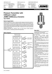
For a correct use of SD-TestBus2 in wireless mode, the USB/Bluetooth adapter must be configured in such a<br />
way that the Bluetooth connection does not requires the PIN code for secure connections. Once the driver and<br />
the adapter have been installed, it is necessary to restart the PC. After the restart, right click with the mouse the<br />
Bluetooth connection icon and access the "Advanced Configuration" menu.<br />
Figure 1. USB/Bluetooth adapter configuration<br />
ABB SACE ABB SD-TestBus2 v. 2.16 1SDH000602R0002 L2937 EN<br />
4 di 28
SD-TestBus 2 v. 2.16<br />
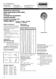
Open the "Client application" tab, select "Bluetooth Serial Port" e click "Properties ...".<br />
Figure 2. Serial port configuration<br />
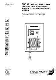
Deselect the "Secure connection" option. Click OK to confirm.<br />
Restart the PC.<br />
Figure 3. "Secure connection" removal<br />
2.4 Start SD-TestBus2<br />
Once the default installation parameters have been set, it is sufficient to launch the program from the Start Menu<br />
pressing the push button “Start” and deselecting the SD-TestBus2 icon, or clicking directly the program icon on<br />
the desktop.<br />
ABB SACE ABB SD-TestBus2 v. 2.16 1SDH000602R0002 L2937 EN<br />
5 di 28
SD-TestBus 2 v. 2.16<br />
3 Main window<br />
The main window is split up into 3 areas as shown in the following figure:<br />
3.1 Device list<br />
This area represents, with a tree view, all the devices detected during the bus scanning. The main node is<br />
represented by the “Modbus” element, while the single devices, are represented as subnodes giving the<br />
whole of icons and names that identify the device type and the address thy are noticed to. For example, a PR113<br />
relay at address 3 will have the nameplate “PR113 @ 3”.<br />
Each device is associated with an icon that changes cyclically according to the following table:<br />
Default icon<br />
It shows the presence of the device and that the ID supplied (Slave ID)<br />
corresponds to that found by SD-TestBus2. The device is connected on system<br />
bus and it is configured in remote mode.<br />
ABB SACE ABB SD-TestBus2 v. 2.16 1SDH000602R0002 L2937 EN<br />
6 di 28
SD-TestBus 2 v. 2.16<br />
It shoes the presence of the device and that the ID supplied (Slave ID)<br />
corresponds to that found by SD-TestBus2. The device is connected through<br />
the Bluetooth module.<br />
Indicates the presence of the device and that the ID supplied (Slave ID)<br />
corresponds to that found by SD-TestBus2. The device is connected on system<br />
bus and is configured in local mode.<br />
It shows the presence of the device and that the ID supplied (Slave ID)<br />
corresponds to that found by SD-TestBus2. The device is connected o the local<br />
bus (for PR121,PR122, PR123, PR331, PR332 and PR333 only).<br />
The device replied but if is of unknown type or it is not possible to determine<br />
the remote/local mode.<br />
The device does not reply or its ID does not corresponds to that found by SD-<br />
TestBus2.<br />
Wink is active.<br />
The device has detected “any alarm” condition.<br />
If the devices found are recognized, a set of pages is shown. Each page contains information and/or commands<br />
the device can perform. Each page is marked by an icon .<br />
Note: in order to make the representation more compact, the pages are “compressed” and are not visualized. To visualize them<br />
lick with the mouse on the “+” that appears next to the device icon.<br />
3.2 Surfing pages<br />
This area is deputed to represent the selected information operating with the mouse in the “nodes” of the device<br />
list. Selecting the root node “Modbus” a summary will be visualized with all the found devices and their<br />
communication parameters. At the same time, selecting with the mouse a single device it will be visualized a<br />
summary on its status and the possible problems found out during the scanning operation. At last, selecting the<br />
nodes “page” the information relevant to the status of protections, measure currents, etc., will be visualized.<br />
ABB SACE ABB SD-TestBus2 v. 2.16 1SDH000602R0002 L2937 EN<br />
7 di 28
SD-TestBus 2 v. 2.16<br />
3.3 Menu bar<br />
This bar contains all the commands that can be carried out by SD-TestBus2. The menu bar is contextual and<br />
changes according to the node selected in the device list.<br />
3.3.1 File<br />
3.3.1.1 Open device list<br />
It is possible to mention the result of the scan previously saved selecting “File\Open device list” and choosing<br />
the .xml file from the directory.<br />
An example named “scanlist.xml” is available in the SD-TestBus2 installation directory.<br />
Opening the file a dialogue window is showed. It is possible to select the COM port the devices are connected<br />
to. If the scan file is generated by the same PC, there is no need to select the COM port: just push “Cancel”.<br />
3.3.1.2 Save device list<br />
It is possible to save the list of the devices found during the scanning in .xml format.<br />
ABB SACE ABB SD-TestBus2 v. 2.16 1SDH000602R0002 L2937 EN<br />
8 di 28
SD-TestBus 2 v. 2.16<br />
3.3.1.3 Print device list<br />
It is possible to print the summary screen that shows the list of all devices found during the bus scanning. To<br />
confirm the print command select the menu voice “Print device list”; to go back to the program select “Close”.<br />
3.3.1.4 Exit<br />
Exit from the program.<br />
3.3.2 Bus<br />
3.3.2.1 Find master<br />
It opens a window that allows setting the communication parameters for the detection of Masters active on the<br />
RS485/RS232 bus.<br />
ABB SACE ABB SD-TestBus2 v. 2.16 1SDH000602R0002 L2937 EN<br />
9 di 28
SD-TestBus 2 v. 2.16<br />
Acting on the “Sniff timeout” item it is possible to set the time delay SD-TestBus2 will be waiting and listening<br />
for intercepting any transmission coming from a mater.<br />
In the “Baudrate” and “Parity” settings it is possible to select the range of scan. The more the selected<br />
combinations, the longer the time requested for completion of the scanning operation. To confirm the operation<br />
press the push button “OK”, otherwise press.<br />
3.3.2.2 Scan<br />
It opens the dialogue window similar to the one described on the Error! Reference source not found. section.<br />
This window allows the scanning parameters of the Slave devices on the bus to be selected. Pressing “OK” the<br />
scanning starts; by pressing the button “X” the dialogue window will be closed.<br />
3.3.2.3 Bluetooth<br />
It activates the Bluetooth antenna for the automatic search of ABB SACE SpA devices fitted with the wireless<br />
communication module within a 10m distance.<br />
3.3.3 Windows<br />
3.3.3.1 Error Log<br />
This command opens a window that contains the errors detected during the communication with the last tested<br />
device.<br />
Note 1: in case of communication errors, this window is automatically opened by SD-TestBus2.<br />
At start up SD-TestBus2 creates a file named “modbus.log”. In this file are reported the last 200 errors occurred<br />
in the communication bus. The analysis of this file may be useful to detect problems on the bus.<br />
Note 2: The “modbus.log” file location is in the SD-TestBus2 installation path (for example “C:\Program Files\ABB\SD-<br />
TestBus”).<br />
Note 3: communication errors are often a normal condition: some noise can generate temporary error on the communication bus.<br />
Otherwise if you notice slow refresh on SD-TestBus2’s pages and a great log activity probably a serious error has occurred<br />
on the bus. If you notice 10 or 15 errors in a time slice of 1 s there is probably a problem on the communication line.<br />
The following example shows a broken bus condition:<br />
***************************************<br />
07/06/2005 - 12:02.56<br />
PR122/P @ 3 time out error<br />
***************************************<br />
***************************************<br />
07/06/2005 - 12:02.56<br />
ABB SACE ABB SD-TestBus2 v. 2.16 1SDH000602R0002 L2937 EN<br />
10 di 28
SD-TestBus 2 v. 2.16<br />
PR122/P @ 3 time out error<br />
***************************************<br />
***************************************<br />
07/06/2005 - 12:02.56<br />
PR122/P @ 3 time out error<br />
***************************************<br />
***************************************<br />
07/06/2005 - 12:02.56<br />
PR122/P @ 3 time out error<br />
***************************************<br />
***************************************<br />
07/06/2005 - 12:02.56<br />
PR122/P @ 3 time out error<br />
***************************************<br />
***************************************<br />
07/06/2005 - 12:02.56<br />
PR122/P @ 3 time out error<br />
***************************************<br />
***************************************<br />
07/06/2005 - 12:02.56<br />
PR122/P @ 3 time out error<br />
***************************************<br />
***************************************<br />
07/06/2005 - 12:02.56<br />
PR122/P @ 3 time out error<br />
***************************************<br />
***************************************<br />
07/06/2005 - 12:02.56<br />
PR122/P @ 3 time out error<br />
***************************************<br />
***************************************<br />
07/06/2005 - 12:02.56<br />
PR122/P @ 3 time out error<br />
***************************************<br />
***************************************<br />
07/06/2005 - 12:02.57<br />
PR122/P @ 3 time out error<br />
***************************************<br />
3.3.4 Password<br />
3.3.4.1 Insert<br />
Inserting a specific password the user’s authorizations change. At present in SD-TestBus2 two use levels are<br />
provided:<br />
Protection level Description<br />
None It allows to scan the bus in search of devices, to visualize some pages<br />
but not to send commands (open/close) or to set the protection<br />
parameters.<br />
User It allows to scan the bus in search of devices, to visualize some pages,<br />
to send commands (open/close) and to set the protection parameters.<br />
ABB SACE ABB SD-TestBus2 v. 2.16 1SDH000602R0002 L2937 EN<br />
11 di 28
SD-TestBus 2 v. 2.16<br />
Note: at the first installation of SD-TestBus2, the default user password is set to 0001.<br />
3.3.4.2 Change<br />
It allows changing the current password with another one at pleasure.<br />
3.3.5 Help<br />
3.3.5.1 XML info<br />
It is possible to access the information about the device describers and their version. The device describers represent the<br />
database used by SD-TestBus2 to identify and manage the devices connected to the bus.<br />
WARNING: any modification of the device describers is strictly forbidden, since it may seriously compromise<br />
SD-TestBus2.<br />
3.3.5.2 Guide<br />
It opens this guide.<br />
3.3.5.3 About SD-TestBus2<br />
It opens a window containing the information on the version of SD-TestBus2.<br />
ABB SACE ABB SD-TestBus2 v. 2.16 1SDH000602R0002 L2937 EN<br />
12 di 28
SD-TestBus 2 v. 2.16<br />
4 Bus scanning<br />
This function allows identifying the devices (slave) connected to the bus, pointing out the characteristic<br />
communication parameters. According to the device type, more pages will be available for protection parameters<br />
setting and for command sending.<br />
From the menu “Bus” select the “Scan” function; a dialogue window will open up allowing choosing scanning parameters.<br />
The “Baudrate” parameter allows selecting the communication speed between the device and SD-TestBus2.<br />
The “Parity” parameter allows selecting the type of error check that is carried out on each transmitted character.<br />
The possible options are:<br />
• “Evenparity”: check of “even” parity;<br />
• “Oddparity”: check of “odd” parity;<br />
• “Noparity”: no parity check.<br />
In the box on the left it is possible to select with the mouse an addresses range within which to perform the<br />
scanning. By ticking off the “Scan Reserved Addresses” option, it will be carried out the device scanning in the<br />
addresses 248-255.<br />
The “Timeout” parameter shows the maximum time expressed in milliseconds, the program will be waiting for<br />
receiving a reply from the device under scanning. If the selected time is too short there is a possibility of not<br />
being able to detect the presence of devices on the bus.<br />
The 100 ms value is an excellent compromise between the scanning velocity and the waiting time.<br />
Acting on the “COM Port” box, it is possible to select the port within which to perform the scanning.<br />
Note 1: if some program is using one or more serial ports (e.g. SD-View2000) these ones will not be visualized.<br />
ABB SACE ABB SD-TestBus2 v. 2.16 1SDH000602R0002 L2937 EN<br />
13 di 28
SD-TestBus 2 v. 2.16<br />
Note 2: it is possible to launch a number of SD-TestBus2 instances equal to the serial ports available on one’s own PC.<br />
At last in the boxes “Baudrate” ad “Parity” it is possible to select the wished scanning intervals likewise the box<br />
“Addresses”.<br />
Note 3: the larger is the selected parameters set, the greater is the number of the combinations to test; as a result, the time to<br />
complete the scanning will be longer.<br />
To confirm press “OK”; to exit press the “X” push button.<br />
During the scanning the progress percentage is visualized in the box on the right.<br />
To end immediately the operation select the item “STOP_SCAN!” in the menu bar.<br />
If some devices are found, they will be visualized both in the device list and in the box of surfing pages where<br />
the main communication parameters will be summarized.<br />
At the end of the operation (each 5s) SD-TestBus2 checks the presence of the devices detected. In the box<br />
“device list” all the devices found are visualized by a tree diagram.<br />
The device’s icon, may change from , showing the right reply of the device, to signaling a device’s<br />
or serial connection’s anomaly.<br />
In the case the device is in local mode (the device can not perform commando), the icon will have the padlock<br />
shape .<br />
Note 5: SD-TestBus2 will signal also the possible presence of not ABB SACE SpA devices.<br />
ABB SACE ABB SD-TestBus2 v. 2.16 1SDH000602R0002 L2937 EN<br />
14 di 28
SD-TestBus 2 v. 2.16<br />
At the end of the scanning SD-TestBus2 will visualize possible Warning or Errors found (for example in case<br />
there are two devices with different baud rate)<br />
ABB SACE ABB SD-TestBus2 v. 2.16 1SDH000602R0002 L2937 EN<br />
15 di 28
SD-TestBus 2 v. 2.16<br />
5 Bluetooth<br />
This function allows identifying ABB SACE SpA devices fitted with the internal wireless Bluetooth<br />
communication module BT030 or with the external one PR120D-M.<br />
From the "Bus" menu select the "Bluetooth" function to activate the adapter. On the screen a pop-up window<br />
will show the search progress.<br />
At the end of the search, the description and serial number of the detected devices will be shown.<br />
With a double click it is possible to access the information of one of the devices detected during the wireless<br />
scan.<br />
ABB SACE ABB SD-TestBus2 v. 2.16 1SDH000602R0002 L2937 EN<br />
16 di 28
SD-TestBus 2 v. 2.16<br />
6 Find master<br />
This function allows discovering the presence of possible master present on the bus, showing the characteristic<br />
communication parameters.<br />
From the "Bus" menu select the voice “Find master". A dialogue window opens allowing choosing various<br />
parameters to perform the scanning.<br />
The parameter “Sniff Timeout” shows the maximum time expressed in milliseconds, the program will be waiting<br />
for intercepting the transmission of a master on the bus. If the selected time is too short there is a possibility of<br />
not being able to detect device’s presence on the bus. The value of 1000 ms is an excellent compromise between<br />
the scanning velocity and the waiting time.<br />
Acting in the box “COM Port” it is possible to select the port within which to perform the scanning.<br />
Note 1: if some program is using one or more serial ports (e.g. SD-View 2000), these ones will not be visualized.<br />
In the boxes “Baudrate” and “Parity” it is possible the selection of the wished scanning intervals.<br />
Note 2: the larger is the selected parameters set, the greater is the number of the combinations to test; as a result the scanning time<br />
will be longer.<br />
To confirm press OK; to exit press the ‘X’ push button.<br />
During the scanning the progress percentage is visualized in the box on the right.<br />
To end immediately the operation select the item “STOP_SNIFF” in the menu bar.<br />
ABB SACE ABB SD-TestBus2 v. 2.16 1SDH000602R0002 L2937 EN<br />
17 di 28
SD-TestBus 2 v. 2.16<br />
7 Interaction with the single device<br />
To interact with a single device select the “pages” (e.g. "TEST", "SETTINGS"...) that appear below each node in<br />
the box “device list”:<br />
Note 1: a changeable number of pages may be present according to the device type.<br />
7.1 Information<br />
In this section it is possible to read general information about the device (SW release, circuit breaker and alarms<br />
status) and send commands (Wink, closing and opening command, Trip reset, etc.).<br />
Note 2: for sending the command it is necessary to be an “authorized” user. The default password is 0001. For more details see<br />
section Error! Reference source not found..<br />
Note 3: t the commands in the page will be visualized in gray color if the device under test is in the local operation modality<br />
; it will not be possible to press the push buttons.<br />
ABB SACE ABB SD-TestBus2 v. 2.16 1SDH000602R0002 L2937 EN<br />
18 di 28
SD-TestBus 2 v. 2.16<br />
7.2 Alarms<br />
All the alarms made available by the device are shown in this page: the “any alarm” status is shown with the<br />
icon into the tree view.<br />
The “any alarm” status is produced by any of the alarms reported in this page: for example alarm condition could<br />
be done by protection timing or by connection errors.<br />
ABB SACE ABB SD-TestBus2 v. 2.16 1SDH000602R0002 L2937 EN<br />
19 di 28
SD-TestBus 2 v. 2.16<br />
7.3 Trips<br />
If the alarm condition has reached a timeout (i.e. L timing) the relay sends a trip command to the circuit breaker<br />
and then enters into the “tripped” status. In this page it is possible to catch information about the cause of the<br />
trip and the protection’s name that has timed out.<br />
Depending on the type of relay, it is possible to read information about previous trips (called Trip history).<br />
7.4 Measures History<br />
In this table are shown the measures of current, voltages and power recorded by the relay. It is possible to define<br />
the time interval between two measures (for ex. 5 min).<br />
ABB SACE ABB SD-TestBus2 v. 2.16 1SDH000602R0002 L2937 EN<br />
20 di 28
SD-TestBus 2 v. 2.16<br />
7.5 Run time measures<br />
In this page are shown all the measures made by the relay at <strong>ru</strong>n time.<br />
It is possible to see the <strong>ru</strong>n time currents, voltages, power and energies depending on the installed relay.<br />
7.6 Settings<br />
The protection settings can be visualized and set up in this page. The information are arranged in a table form;<br />
each row contains the name of the item, its current value and a list box menu showing the value whole that the<br />
item may assume. Choose the wanted value from the menu. More selections about different items are possible;<br />
the new values are transferred to device only after pressing the push button “Submit”.<br />
ABB SACE ABB SD-TestBus2 v. 2.16 1SDH000602R0002 L2937 EN<br />
21 di 28
SD-TestBus 2 v. 2.16<br />
During the transfer of the data to the device, for each item modified will be visualized the indication "old_value--<br />
-> new_value" (e.g. "10 ---> 12") to indicate that the writing operation is under execution. When the writing is<br />
completed the indication will change in "new_value".<br />
For sending the data it is necessary to be an “authorized” user. The default password is 0001. For more details<br />
see section Error! Reference source not found..<br />
WARNING: the sending to the device of some value arrangements (e.g. not cong<strong>ru</strong>ent protection threshold)<br />
may cause an error message. In this case the page will be refreshed with the relay current value.<br />
Note 1: when the device under test is in the local operating modality , all the writing commands are disabled.<br />
Note 2: to cancel the modifications in the selections it is sufficient to press the pushbutton “Reset”.<br />
Note 3: according to the type of selected voice, TEST, SETTINGS, etc. it is possible to print a test report and to save/load<br />
the relay settings in the menu “File”.<br />
ABB SACE ABB SD-TestBus2 v. 2.16 1SDH000602R0002 L2937 EN<br />
22 di 28
SD-TestBus 2 v. 2.16<br />
7.6.1 Current time curve<br />
With some relays it is possible to have a graphical representation of the protection set (L, S, I and G protections).<br />
To open this window you have to push the button named “Curve current / time”.<br />
On the menu bar is made possible to print the current view, to change the current scale (Ampere or In) and to<br />
close the window.<br />
Note 1: the I1 current threshold is drawn at about 117% (IEC) or 105% (UL) of its nominal value. This is done according to<br />
the respective standards.<br />
Note 2: it is possible to change the protection set without close the window. At the end of the programming session, the window is<br />
automatically refreshed with the new parameters. If there is a communication problem or an incoherent parameter set a<br />
“?” icon is shown.<br />
7.7 Communication settings (only for PR222DS/PD and PR223EF)<br />
This page is visualized only if the device found on the bus belongs is a PR222DS/PD or PR223EF. Here is some<br />
information about the configuration of the communication unit.<br />
ABB SACE ABB SD-TestBus2 v. 2.16 1SDH000602R0002 L2937 EN<br />
23 di 28
SD-TestBus 2 v. 2.16<br />
The item “Address” shows the logical address of the device on the bus, and may be changed by the list box<br />
menu on the right. Admissible values are from 1 to 247.<br />
The item “Addressing” shows the access modality of SD-TestBus2 to different records of the device. The two<br />
possibilities are:<br />
• “Standard”: in this modality the records are mapped according to the standard Modbus;<br />
• “ABB”: in this modality the records are mapped according to the standard owner ABB.<br />
Note 1: the selection of the addressing modality does not compromise the functionality of the device and of SD-TestBus2, however<br />
is good manner that all the devices on the bus will have the same addressing type.<br />
The voice “Baudrate” allows selecting the communication speed between the device and SD-TestBus2. The two<br />
choices are 19200 and 9600 characters per second.<br />
The voice “Parity” allows to select the type of error check that is carried out on each transmitted character. The<br />
possible options are:<br />
• “Even”: check of even parity;<br />
• “Odd”: check of odd parity;<br />
• “None”: no check of parity.<br />
WARNING: Even though SD-TestBus2 allows managing more devices with different communication<br />
parameters, it is highly advisable to maintain the same addressing, baud rate and parity for all devices on<br />
the same bus. Before changing the logical address of the device (“Address”), verify that this is not<br />
already in use by another device. Otherwise the communication with both devices will be lost.<br />
Note 2: when one or more communication parameters are modified, SD-TestBus2 “follows” these changes resetting the serial<br />
port. The communication with the device is not lost so the user is not forced to do a new scanning operation.<br />
7.8 Statistics<br />
In this table are shown the number of operations, subdivided by typology.<br />
Note: the manual operations item is updated when the CB changes its status from CLOSE to OPEN.<br />
ABB SACE ABB SD-TestBus2 v. 2.16 1SDH000602R0002 L2937 EN<br />
24 di 28
SD-TestBus 2 v. 2.16<br />
7.9 Signaling Status<br />
In this page are shown the status of the contacts installed on the relay:<br />
• PR010/K, PR020/K, PR021/K external contacts module;<br />
• PR120/K internal contacts module (see 7.10);<br />
• Input status on PR120/K.<br />
It is possible to reset contacts status by pushing the button “Signaling reset”.<br />
7.10 PR120/K Configuration<br />
In this page is possible to setup the behavior of the PR120/K module. This optional module has 4<br />
programmable contacts (outputs) and one input named “Signaling module input”. For each contact there are<br />
four items to be selected.<br />
1. The “Contact status” item can assume two values:<br />
• “NO”: contact is normally open;<br />
• “NC”: contact is normally close;<br />
2. “Contact Latch” establish the behavior of the contact:<br />
• “Not latched”: the output stays active when the programmed event is set. When the event is no<br />
more verified the corresponding contact return to its inactive status;<br />
• “Latched”: the output stay active when the programmed event is set for the first time. When the<br />
event is no more verified the corresponding contact does not return to its inactive status<br />
3. “Function”: it is possible to select a simple event function from the menu showed. If needed, it is<br />
possible to set up a custom event by pressing the “Custom” button.<br />
4. “Delay”: defines the delay between the event changing status (to verified) and the corresponding contact<br />
response.<br />
ABB SACE ABB SD-TestBus2 v. 2.16 1SDH000602R0002 L2937 EN<br />
25 di 28
SD-TestBus 2 v. 2.16<br />
7.11 Data logger<br />
The Emax series PR122 and PR123 has the ability to record the current and voltage signals of the plant.<br />
In this page it is possible to set the sampling frequency, to set a custom event and to set the delay between the<br />
trig event and the end of the recordings.<br />
Note 1: the total time capacity of the data logger depends on the selected sampling rate. It can vary between 3s (sampling frequency<br />
equal to 4800Hz) and 27s (sampling frequency set to 600Hz). It is important to choose the proper<br />
sampling frequency: too low sampling frequency may affect signal’s representation. This is<br />
caused by noise and plant harmonics at frequencies above 50 or 60 Hz. For further information<br />
please refer to the Emax PR122 or PR123 user manual.<br />
Note 2: the data logger can be set to be “free <strong>ru</strong>nning” or “triggered on event”. In the first case the user have to stop manually the<br />
recording of the data logger. In the second, a stop command is sent by the relay when a particular event (i.e. any trip or<br />
any alarm or a custom event) occurs. The trip event has the priority: when this event occurs the relay<br />
stops the data logger (even if it is in “free <strong>ru</strong>nning”).<br />
To start an acquisition push the “Trigger restart” button. You can notice a “Waiting trigger” item on the top of<br />
the “Status” box. Warning: the “Trigger restart” command has to be sent only if the data logger is “enabled”.<br />
To stop the data logger acquisition, push the “Data logger stop” button.<br />
To download the content of the data logger to a file push the “Download” button.<br />
7.12 Local/remote modality management<br />
For safety reasons, when the device is in local modality , SD-TestBus2 does not allow the command<br />
sending. It is necessary, therefore, to interact with the frontal panel of the device and to set the remote operation<br />
modality. Within 5 seconds, SD-TestBus2 will find the setting change and automatically will allow to the user to<br />
send the commands or to set the protection parameters.<br />
ABB SACE ABB SD-TestBus2 v. 2.16 1SDH000602R0002 L2937 EN<br />
26 di 28
SD-TestBus 2 v. 2.16<br />
8 SD-View2000 Configurator Plug-in<br />
SD-View 2000 Plug-in for SD-TestBus2 is an application that allows to use the information got from SD-<br />
TestBus2’s Modbus scan process for configuring SD-View 2000. This will reduce the configuration time and<br />
make the engineering process easier, more consistent and less error-prone.<br />
Usually, the configuration engineer is required to use SD-View 2000 Configurator for configuring SD-View<br />
2000. This is the main and most flexible procedure, but it requires to manually set the configuration.<br />
The plug-in can be seen as a simplified version of SD-View 2000 Configurator, where most of the configuration<br />
data is taken from SD-TestBus2.<br />
SD-View 2000 Configurator Plug-in for SD-TestBus2 can be used even when a previous SD-View 2000<br />
version exists.<br />
The plug-in is able to determine whether the information found by SD-TestBus2 are in conflict with what<br />
previously configured in SD-View 2000. If this is the case, the user will be alerted.<br />
The plug-in is based on SD-View 2000 Configurator and it requires SD-View 2000 to be installed on the same<br />
computer where SD-TestBus2 is <strong>ru</strong>nning. For further information read “Getting started with SD-View2000”<br />
(<strong>doc</strong>. 1SDH000513R0002).<br />
9 Summary of last scanning<br />
To have a summary of the last scanning carried out, select the node “Modbus” in the device list.<br />
10 FAQs<br />
10.1 The program does not start and gives a message “No available COM port found!”<br />
At start SD-TestBus2 is looking for the serial ports supplied from the PC in use. On some portable PC of last<br />
generation it is possible that the COM ports are emulated. It is necessary to set them in a proper way so that<br />
SD-TestBus2 may use them rightly. Besides, verify that the serial ports are not already in use in another software,<br />
for example SD-View 2000.<br />
10.2 The scanning operation does not find any device<br />
Check that the relay is correctly powered. Make sure that the serial cable and the converter RS-232/ RS-485 is<br />
correctly supplied. Besides, check that the polarity of the two cables of the bus 485 is right. In case, act on<br />
parameter “Timeout” to increase the waiting time during the scanning. In case, mark the item “Search in the<br />
reserved addresses” to find devices with not configured communication.<br />
10.3 The scanning operation finds unknown devices with consecutive addresses<br />
Make sure that the polarity of the bus 485 cables is right and that at rest the line is correctly polarized. Go to<br />
“Bus\Find master” to check the presence of a master (e.g. SD-View 2000) which is transmitting on the bus.<br />
10.4 During the scanning one or more unknown devices are found even if in the switchboard there are<br />
SACE devices.<br />
Verify that the devices do not communicate on the bus at the same address. In case, dissect the bus and set one<br />
at a time the devices with different addresses.<br />
ABB SACE ABB SD-TestBus2 v. 2.16 1SDH000602R0002 L2937 EN<br />
27 di 28
SD-TestBus 2 v. 2.16<br />
10.5 I have found some PR010K /PR020K /PR021K unit.<br />
Attention, the wirings are wrong. These units have not to be visible to SD-TestBus2.<br />
10.6 SD-TestBus2 has found a device but it does not show the pages.<br />
Make sure that on the left of the icon there is the signal “+”. On the contrary, select the device and in the surfing<br />
window check the item “Problem”. They may be several reasons:<br />
• Unknown device, SD-TestBus2 does not support this device or two or more devices communicate on<br />
the same address;<br />
• Describer not valid, the file xml has been cor<strong>ru</strong>pt. It is necessary to install again SD-TestBus2.<br />
10.7 SD-TestBus2 has found the device but loses the communication<br />
Make sure that the line RS-232 and the bus 485 are not too much disturbed (interferences with supply cables,<br />
mobile phones, etc.)<br />
10.8 I try to send a command but SD-TestBus2 ask me a password<br />
To send a command it is necessary to be authorized users.<br />
10.9 I try to send a command but the push buttons do not work<br />
Make sure that the device is in remote modality (alternation icons and ). On the contrary, set the<br />
remote operation node on the relay panel.<br />
10.10 I try to carry out a command but an error window opens with the message “Modbus device return<br />
an exception code...”<br />
It means that the device has received the command but is not in condition to perform it.<br />
10.11 During the surfing of pages, a page in evidence appears with some error messages.<br />
Occasionally some communication errors caused by noise may occur (timeout error, CRC error, etc.). To avoid<br />
that this window appears continually, minimize it pressing the push button .<br />
10.12 SD-TestBus2 show always the same serial number.<br />
Every relay has its own serial number that is read (once) during scan operation. If the relay under test is changed<br />
(e.g. by bus switch) with another one (of the same type) with the same slave address, the serial number will not<br />
be refreshed. New devices connected to the bus have to be detected always with a bus scan.<br />
10.13 Local bus connection.<br />
The PR12X and PR33X relays have built in a point-to-point bus for Modbus communication. It means that,<br />
without the PR120/D-M module, it is made possible to wire the W3 and W4 contacts and communicate with an<br />
RS-485 converter. The bus parameters are fixed: address 3, baud rate 19200, even parity and 1 stop bit.<br />
When local bus is used for connection, SD-TestBus2 shows the icon on the tree list view. It is not<br />
possible to connect more than one device on the local bus: it can cause conflicts and communication<br />
problems.<br />
10.14 The signaling module doesn’t work<br />
It is possible that the contact activation delay is greater than the event duration when the contact behavior is set<br />
to “Not Latched”. If possible try to decrease the delay or set the contact to “Latched”.<br />
ABB SACE ABB SD-TestBus2 v. 2.16 1SDH000602R0002 L2937 EN<br />
28 di 28