Chatsworth Assembly Sheet.qxd - Taylors Garden Buildings
Chatsworth Assembly Sheet.qxd - Taylors Garden Buildings
Chatsworth Assembly Sheet.qxd - Taylors Garden Buildings
- No tags were found...

You also want an ePaper? Increase the reach of your titles
YUMPU automatically turns print PDFs into web optimized ePapers that Google loves.
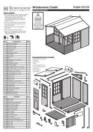
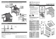
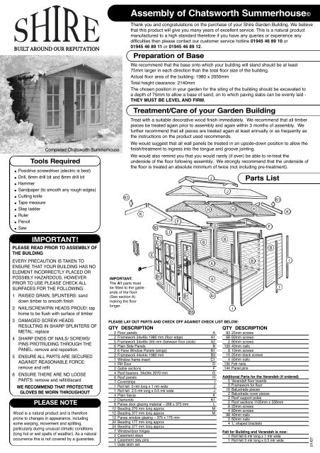
BUILT AROUND OUR REPUTATION●●●●●●●●●●Completed <strong>Chatsworth</strong> SummerhouseTools RequiredPosidrive screwdriver (electric is best)Drill, 6mm drill bit and 8mm drill bitHammerSandpaper (to smooth any rough edges)Cutting knifeTape measureStep ladderRulerPencilSawIMPORTANT!PLEASE READ PRIOR TO ASSEMBLY OFTHE BUILDINGEVERY PRECAUTION IS TAKEN TOENSURE THAT YOUR BUILDING HAS NOELEMENT INCORRECTLY PLACED ORPOSSIBLY HAZARDOUS, HOWEVERPRIOR TO USE PLEASE CHECK ALLSURFACES FOR THE FOLLOWING:1 RAISED GRAIN, SPLINTERS: sanddown timber to smooth finish2 NAIL/SCREW/PIN HEADS PROUD: taphome to be flush with surface of timber3 DAMAGED SCREW HEADSRESULTING IN SHARP SPLINTERS OFMETAL: replace4 SHARP ENDS OF NAILS/ SCREWS/PINS PROTRUDING THROUGH THEPANEL: remove and reposition.5 ENSURE ALL PARTS ARE SECUREDAGAINST REASONABLE FORCE:remove and refit6 ENSURE THERE ARE NO LOOSEPARTS: remove and refit/discardWE RECOMMEND THAT PROTECTIVEGLOVES BE WORN THROUGHOUTPLEASE NOTEWood is a natural product and is thereforeprone to changes in appearance, includingsome warping, movement and splitting,particularly during unusual climatic conditions(long hot or wet spells of weather). As a naturaloccurrence this is not covered by a guarantee.K1<strong>Assembly</strong> of <strong>Chatsworth</strong> Summerhouse©Thank you and congratulations on the purchase of your Shire <strong>Garden</strong> Building. We believethat this product will give you many years of excellent service. This is a natural productmanufactured to a high standard therefore if you have any queries or experience anydifficulties then please contact our customer service hotline 01945 46 89 10 or01945 46 89 11 or 01945 46 89 12.Preparation of BaseWe recommend that the base onto which your building will stand should be at least75mm larger in each direction than the total floor size of the building.Actual floor area of the building: 1980 x 2050mmTotal height clearance: 2140mmThe chosen position in your garden for the siting of the building should be excavated toa depth of 75mm to allow a base of sand, on to which paving slabs can be evenly laid -THEY MUST BE LEVEL AND FIRM.Treatment/Care of your <strong>Garden</strong> BuildingTreat with a suitable decorative wood finish immediately. We recommend that all timberpieces be treated again prior to assembly and again within 3 months of assembly. Wefurther recommend that all pieces are treated again at least annually or as frequently asthe instructions on the product used recommends.We would suggest that all wall panels be treated in an upside-down position to allow thefinish/treatment to ingress into the tongue and groove jointing.We would also remind you that you would rarely (if ever) be able to re-treat theunderside of the floor following assembly. We strongly recommend that the underside ofthe floor is treated an absolute minimum of twice (not including pre-treatment).KIMPORTANT.The A1 parts mustbe fitted to the gableends of the floor(See section A)making the floorlonger.EB3C1B1L1DPLEASE LAY OUT PARTS AND CHECK OFF AGAINST CHECK LIST BELOW:QTY DESCRIPTION2 Floor panels A2 Framework 34x46x 1980 mm (floor edge) A15 Framework 34x46x 345 mm (between floor joists) A26 Plain Side Panels B2 6 Pane Window Panels (wings) B12 Framework 44x44x 1980 mm B31 Window frame insert C11 RH Door D2 Gable sections F4 Roof bearers 34x34x 2070 mm G6 Roof panels H7 Coverstrips I1 Roll felt 5 mtr long x 1 mtr wide J1 Roll felt 2.5 mtr long x 0.5 mtr wide J4 Plain fascia K2 Diamonds K16 Panes door glazing material – 268 x 373 mm L12 Beading 270 mm long approx M12 Beading 377 mm long approx M12 Panes window glazing – 375 x 175 mm24 Beading 177 mm long approx24 Beading 377 mm long approx7 Window/door hinges2 Casement stays4 Casement stay pins1 Gate latch setFC1B1B3BHJAAGA1BA2JHIParts ListBHQTY DESCRIPTION83 25mm screws68 60mm screws2 80mm screws129 40mm nails8 10mm screws10 25mm black screws4 50mm nails130 Felt nails144 Panel pinsAdditional Parts for the Verandah (if ordered)5 Verandah floor boards5 Framework for floor10 Balustrade pieces2 Balustrade cover pieces2 Roof support poles2 Roof sections 1105mm x 336mm8 25mm screws4 80mm screws98 40mm nails2 60mm nails4 ‘L’ shaped bracketsFelt for Building and Verandah is now:1 Roll felt 6 mtr long x 1 mtr wide1 Roll felt 3 mtr long x 0.5 mtr wideFBK1IKI01/07
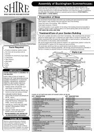
<strong>Assembly</strong> of Building - PLEASE READ INSTRUCTIONS PRIOR TO ASSEMBLYA - Floor <strong>Assembly</strong>1 Take one floor panel 'A' and a pieceof framework 34x46x1980 mmapprox 'A1'. Place the framework onthe OPEN edge of the floor so thatthe framework is flush and level withthe boarding and joists. Look wherethe floor joist meet the frameworkand mark. Drill at these marks.Secure to floor using 6x 60 mmscrews.B - Fit Window Insert C1 (from top)1 Place one hinge on the innerrebate part of the top of the window.The rounded part of the hingeshould sit above the outer edge ofthe window. Screw the inner pieceinto position using the pre drilledholes in the hinge and 2x 25mmscrews. Repeat.5 Fit the Casement Stay on thewindow using 2x 25mm screws.5 Three hinges need to spaced alongthe door – one centrally, onetowards the top and one toward thebottom. Place one hinge on theinner rebated part of the edge of thedoor. Screw the inner piece of oneinto position using the pre drilledholes in the hinge and 2x 25 mscrews. Repeat for other twohinges on door.6 Mark where the ‘pins’ will be placed.2. Repeat item 1 with one more floorsection.3. Place floors on your firm levelbase, board side up. Take 5 piecesframework 'A2', 34x46x345 'A2'and place between each floor joist.Nail half of the widest part to thefloor using 3x 40 mm nails perpiece.2 Place the window into the aperture.Secure the window to the panelusing 3x 25mm screws per hinge,again through the predrilled holes inthe hinge. Repeat.3 Open the window and fit a further 2x25mm screws per hinge next to theone already fitted in Step 1. Repeat.7 Secure into position using4x 25mm screws - 2 in each pin.C - Front <strong>Assembly</strong>6 Place the door ‘D’ on a flat, levelsurface with the inside facingupwards. Place wing panelassembly on top of the doors sothat the doors fit inside the aperture.7 Secure the doors to the panel using1x 25 mm screw per hinge throughthe predrilled centre holes of eachhinge. Repeat for all hinges.8 Open the door fully and fit a further3x 25mm screws per hinge.D - Wall <strong>Assembly</strong>4. Once all frameworks are fittedbetween floor joists slide anotherfloor on top of the framework andsecure again using 3x 40 mm nailsper floor joist.4 Fitting the Casement Stay. Placethe casement stay centrally on theinside of the window. Place the 2pins under the casement stay.Position so that it is not resting onthe framework of the panel and notso high that the pins are of no use.1 Lay wing panels ‘B1’ on a flat, cleansurface with framework facingupwards.2 Take two lengths of framework ‘B3’44x44 x 1980 mm. Place one ateach end of wing panels ‘B1’, to runflush with both outer edges of parts‘B1’.3 The horizontal gap where the doorsare to go should measure approx.676 mm.4 Drill/screw parts ‘B3’ and ‘B1’ atboth ends using a total of 8x 60 mmscrews.1. Decide where the window panel isto go. Place one side panel 'B' onthe floor at the right hand corner.Place a further panel 'B' inside thepanel already in place. THEPANELS ALONG THE BACKWALL SHOULD EXTEND FROMFLOOR EDGE TO FLOOR EDGE.The panels to go at the side screwTO and fit INSIDE the panels to goat the back.2. Drill 2 holes, one to the top andone to the bottom. Do not drill intoadjacent panels. Secure thepanels together using 2x 60 mmscrews.3. Repeat for all plain side panels andalso complete front assembly.
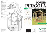
E - Gable <strong>Assembly</strong>1. Place one gable section 'F' on topof the back walls. Drill 4 timesalong the length and secure using4x 60 mm screws.G - Fit Roof Panels7 Nail through roof boarding into sidewall using 3x 40 mm nails per roofpanel.8 Repeat for all roof panels, exceptfront ones.1 If applicable, place small roofpanels at the back of thebuilding. Place roof sections ‘H’ inpairs. The side where the boardingextends past the framework is to goat the ridge. Take 2 roof panels.On the framework to go at the ridgemeasure and mark at 46 mm ofboth panels from ONE end themark is therefore mirrored.9 Place both front roof panels inposition. Mark where the roof framemeets the gable on the inside andoutside.3 Place the lever rest on door ‘G2’ inposition – the gate latch should behorizontal. Screw into position using2 x 25mm black screws.I - <strong>Assembly</strong> of Verandah Floor2. Repeat at front.F - Fit Roof Bearers1. Take 4 roof bearers 34x34x 2070mm 'G'.2. Place in opposite guide holes ofboth gables.3. Drill and screw bearer to gableusing 1x 60mm screw.IMPORTANT ENSURE GABLE ISAT 90'. Repeat for all roof bearers.2 Cut out the framework at thismeasurement of both panels.Remove the nails.3 Place both panels on the walls atthe back, flush and even with theback wall - the cutout at the back.10 Cut the framework at thismeasurement and remove.Repeat. Remove any nails.11 Screw the front roof panels to thefront wall using 3x 25 mm screwsin each side. Nail roof panels tocentre roof beam and side wallusing 3x 40 mm nail in eachposition.H - Fit Hardware to Doors1 Place the five short pieces offramework on a flat, level surface.Place one piece of floor boarding ontop. Nail the floor board to the pieceof framework ensuring that theedges are flush and even. Use 2x40mm nails. Repeat at the otherend of the floor board. Do not nailany of the middle pieces offramework to the floor board justyet.4. Drill/screw roof bearers at ridgetogether using 4x 60 mm screws.4 Secure to the back gable using 3x40 mm nails into each gable.5 Inside, drill/screw at ridge throughframe of roof panel into roof bearer.Secure using 2x 60 mm screw foreach roof panel.6 Nail from outside into the roofbearers using 3x 40 mm nails foreach roof panel/bearer.1 Open doors and secure hingesusing remaining 4 x 25mm screwson each hinge.2 Position the handle with the gatelatch against the door from theoutside of the building. Check thatthe handle is located centrally, markand drill a hole. Push the metal barthrough the hole. Attach the gatelatch handle on the outside and thering handle on the inside. Secureboth in position using 4 x 25mmblack screws per handle.2 Using a floor board as a spacer,place a second piece next to the onenailed in place, only nailing the floorboard to the end two short floorbeams, using 2 x 40mm nails perfloor board per floor beam. Repeatuntil all the floorboards are in place.3 There will be about 2 cm of shortfloor bearer left without a floorboard.
4 Measure 40cm from one edge andmark the floorboard at either end.This will be the centre of one shortfloor beam. Continue measuringand marking at 40cm intervals.L - Felt RoofN - Fit Coverstrips5 Nail all short floor beams into place,again using 2 x 40mm nails in eachfloorboard/floor beam.J - <strong>Assembly</strong> of Verandah Balustrade2 Place the verandah floor - againstthe building. The side of the floorwhere the floor boards and floorframework are level along the lengthis the front. Place one balustradeassembly on the verandah floorand. attach to the building using 1 x25mm screws for each L shapedbracket. Repeat.3 Place large pole against the railing.Mark where the top and bottom ofthe railing meet the framework.Repeat.1 Two rolls of felt ‘J’ have beensupplied. Lay out the largest rolland cut in half length ways..1 Cover strips ‘I’ are nailed over thejoins between all side panels and ateach corner. Secure in place using4x 40mm nails per strip.O - Fascias & Diamond <strong>Assembly</strong>1 Fit 2 plain fascia boards ‘K’ to thefront of either side of the roof. Fit 2more fascias at the back. Secureusing 3x 40mm nails per piece.1 Take one piece of short balustradeframework and place next to theverandah floor, place the other thedistance of the balustrade railingaway. Place all the balustraderailings in line with the verandahfloor.2 Starting at the loweredge (the eaves)place one 1 mtr widepiece from the front tothe back of the building. Anoverhang of approximately 45mmshould be allowed on each of the 3sides although the felt will overhangat the back by more than this.Secure the felt using felt nailsspaced at 100mm intervals. Repeat,but do not nail along the centre ofthe building until the piece of feltcovering the ridge is in place.2 Carefully trim off excess felt withcutting knife against the edge of thefacia board.2 Nail the balustrade railings to bothpieces of framework using 4 x 40mmnails per railing, two at either end.Repeat.4 Drill holes at the marks and screw tothe balustrade assembly using 2 x80mm screws per railing assembly.3 To the inside of the completedbalustrade assembly fit an L shapedbracket to the top and bottom of oneend. Secure using 1 x 25mm screwsfor each bracket. Repeat.K - Fitting of Balustrade <strong>Assembly</strong> to Building5 Nailcoverstripsto top ofbalustradeassemblyusing 4 x40mm nailsper railing.Repeat.7 Ensure the post is upright. Nailthrough the roof panel into the poleusing one 60mm nail per pole.3 Place the smallest piece of felt atthe peak (ridge) of the building. Thispiece will overlap both of the otherpieces of felt. Nail into positionalong both edges of this piece andat both ends.M - Secure Walls to Floor3 Nail diamonds ‘K1’ on top of and inthe centre of the facia board using2x 40mm nails per diamond.P - Fit Glazing Material1 Place glazing material ‘L’ into theaperture of each window.2 Hold into position with four pieces ofbeading ‘L1’. The beading mayneed to be swapped around to getthe best fit. When satisfied secureinto position using 2x 15mm panelpins per piece of beading. Repeatfor all window and door apertures.1 Place large piece framework againstthe corner of the building, ensuringthat the pole is firmly on the ground -at the same level as the front of theverandah. Mark the height and angleand cut off.1 Screw all side panels to the floor onthe inside of the building using 1x60mm screw per separate paneland 1x 80mm screws into each ofthe two panels ‘B1’ either side of thedoors.<strong>Assembly</strong> Completion Checklist1 Check and ensure that no raised grain orsplinters are evident on timber components.Sand down any raised grain or splintersusing fine grade sandpaper.2 Check that all screw, nail and pin heads areproperly tapped home and are not proud ofthe timber surface.3 Check and ensure that no screws, nails orpins protrude through any panel.4 Check and ensure that all parts are properlysecured against reasonable force.5 Do not apply decorative woodfinish/treatments to wet or damp timber.Please observe the instructions of the woodfinish/treatment manufacturer.