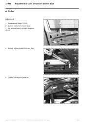
W140 Fault Codes_ Description.pdf
W140 Fault Codes_ Description.pdf
W140 Fault Codes_ Description.pdf

You also want an ePaper? Increase the reach of your titles
YUMPU automatically turns print PDFs into web optimized ePapers that Google loves.
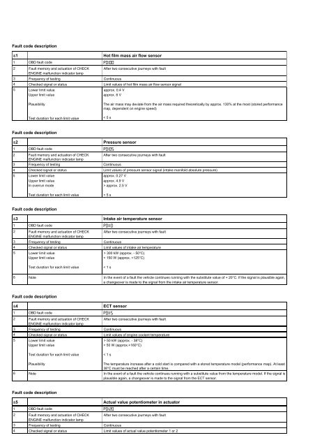
<strong>Fault</strong> code description&1 Hot film mass air flow sensor1 OBD fault code P0I002 <strong>Fault</strong> memory and actuation of CHECK After two consecutive journeys with faultENGINE malfunction indicator lamp3 Frequency of testing Continuous4 Checked signal or status Limit values of hot film mass air flow sensor signal5 Lower limit valueUpper limit valueapprox. 0.4 Vapprox. 6 VPlausibilityTest duration for each limit valueThe air mass may deviate from the air mass required theoretically by approx. 130% at the most (stored performancemap, dependent on engine speed)< 5 s<strong>Fault</strong> code description&2 Pressure sensor1 OBD fault code P0I052 <strong>Fault</strong> memory and actuation of CHECK After two consecutive journeys with faultENGINE malfunction indicator lamp3 Frequency of testing Continuous4 Checked signal or status Limit values of pressure sensor signal (intake manifold absolute pressure)5 Lower limit valueUpper limit valueIn overrun modeapprox. 0.27 Vapprox. 4.9 V> approx. 2.5 VTest duration for each limit value< 5 s<strong>Fault</strong> code description&3 Intake air temperature sensor1 OBD fault code P0II02 <strong>Fault</strong> memory and actuation of CHECK After two consecutive journeys with faultENGINE malfunction indicator lamp3 Frequency of testing Continuous4 Checked signal or status Limit values of intake air temperature5 Lower limit valueUpper limit value> 300 kW (approx. - 50°C)< 150 W (approx. +125°C)Test duration for each limit value< 1 s6 Note In the event of a fault the vehicle continues running with the substitute value of + 20°C. If the signal is plausible again,a changeover is made to the signal from the intake air temperature sensor.<strong>Fault</strong> code description&4 ECT sensor1 OBD fault code P0II52 <strong>Fault</strong> memory and actuation of CHECK After two consecutive journeys with faultENGINE malfunction indicator lamp3 Frequency of testing Continuous4 Checked signal or status Limit values of engine coolant temperature5 Lower limit valueUpper limit value> 50 kW (approx. - 38°C)< 50 W (approx.+160°C)Test duration for each limit value< 1 sPlausibilityThe temperature increase after a cold start is compared with a stored temperature model (performance map). At least38°C must be reached after a certain time.6 Note In the event of a fault the vehicle continues running with a substitute value from the temperature model. If the signal isplausible again, a changeover is made to the signal from the ECT sensor.<strong>Fault</strong> code description&5 Actual value potentiometer in actuator1 OBD fault code P0I202 <strong>Fault</strong> memory and actuation of CHECK After two consecutive journeys with faultENGINE malfunction indicator lamp3 Frequency of testing Continuous4 Checked signal or status Limit values of actual value potentiometer 1 or 2
5 Actual value potentiometer 1Lower limit valueUpper limit value< 0.355 V> 4.765 VActual value potentiometer 2Lower limit valueUpper limit value< 0.295 V> 4.63 V<strong>Fault</strong> code description&6 Oxygen sensor signal1 OBD fault code P0I30 right before TWCP0I36 right after TWCP0I50 left before TWCP0I56 left after TWC2 <strong>Fault</strong> memory and actuation of CHECK After two consecutive journeys with faultENGINE malfunction indicator lamp3 Frequency of testing Continuous4 Checked signal or status A. Limit values of oxygen sensor signalB. Sensor status change5 A. Limit values of oxygen sensor signalLower limit valueUpper limit valueDuration of test< - 0.15 V> 1.5 V< 5 sB. Sensor status changeAfter approx. 220 s with the sensor heater switched on the sensor signal must not dwell in the 0.4 V - 0.6 V voltagewindow for more than approx. 5s6 Test conditions - Engine speed approx. 1000 - 2000 rpm- Load approx. 15 - 50 %- Three-way catalytic converter temperature > approx. 300°C- Lambda control enabled7 Note All electrical connection faults of the oxygen sensors before TWC or after TWC are recognized by means of the tests(cable open-circuit and short-circuit to ground or battery voltage).<strong>Fault</strong> code description&7 A Oxygen sensor ageing correction value exceededB Oxygen sensor ageing period too long1 OBD fault code P0I33 right before TWCP0I53 left before TWC2 <strong>Fault</strong> memory and actuation of CHECK After two consecutive journeys with faultENGINE malfunction indicator lamp3 Frequency of testing Continuous4 Checked signal or status A Correction value exceededB Period too long5 A Limit values of correction valueB Period of limit valueDuration of testapprox. F 1.2 s (ATV)> approx. 5 s (average value from 15 measurements)< 80 s6 Test conditions - Engine speed approx. 1000 - 2000 rpm- Load approx. 15 - 50 %- Three-way catalytic converter temperature > approx. 300°C- Lambda controls enabled- No fault with three-way catalytic converter operation- No fault with oxygen sensor heater7 Test sequence The oxygen sensors after the TWC are required to check the three-way catalytic converter efficiency and to improvethe Lambda control (two-sensor control).The Lambda mean value is formed from the oxygen sensor signals and from it a correction value is determined forthe Lambda control. The ageing of the oxygen sensor before TWC is compensated for within certain limits by thecorrection value (value with new oxygen sensor approx. 0). If the correction value exceeds the limit value, the oxygensensor before TWC must be replaced. The period of the sensor signal is also evaluated.8 Note The period of the oxygen sensor before TWC is too long: Oxygen sensor after TWC does not continue to bemonitored. Correction value of oxygen sensor before TWC exceeded: Oxygen sensor after TWC continues to bemonitored. If the faults for the oxygen sensor before and after TWC are recognized at the same time, usually only theoxygen sensor after TWC is defective.<strong>Fault</strong> code description&8 Oxygen sensor heater1 OBD fault code P0I35 right before TWCP0I4I right after TWCP0I55 left before TWCP0I6I left after TWC2 <strong>Fault</strong> memory and actuation of CHECK After two consecutive journeys with faultENGINE malfunction indicator lamp3 Frequency of testing Continuous4 Checked signal or status Calculated resistance value of sensor heater5 Lower limit valueUpper limit value< approx. 2.0 W (corresponds to approx. 6 A at 12 V)> approx. 9.2 W (corresponds to approx. 1.3 A at 12 V)6 Note The oxygen sensor heaters of the oxygen sensors before TWC or after TWC are connected in parallel7 Test conditions Sensor heater ON and heating-up time of approx. 220 s elapsed<strong>Fault</strong> code description
<strong>Fault</strong> code description&13 CKP sensor1 OBD fault code P03352 <strong>Fault</strong> memory and actuation of CHECK After two consecutive journeys with faultENGINE malfunction indicator lamp3 Frequency of testing Continuous4 Checked signal or status CKP sensor signal (counting the teeth on flywheel)5 Lower limit valueUpper limit value(60 - 2 teeth) - 1 tooth(60 - 2 teeth) + 1 toothDuration of test< 5 s<strong>Fault</strong> code description&14 Camshaft Hall-effect sensor1 OBD fault code P034I2 <strong>Fault</strong> memory and actuation of CHECK After two consecutive journeys with faultENGINE malfunction indicator lamp3 Frequency of testing Continuous4 Checked signal or status Camshaft Hall-effect sensor signal5 PlausibilityNo signalNumberThe signal must change from 0 - 1 and from 1 - 0 within 2 engine revolutionsMax. 1 signal change per engine revolution6 Test conditions - Engine speed 25 - 6300 rpm- No CKP sensor fault<strong>Fault</strong> code description&15 Secondary air injection (functional chain)1 OBD fault code P04I02 <strong>Fault</strong> memory and actuation of CHECK After two consecutive tests with faultENGINE malfunction indicator lamp3 Frequency of testing Once per journey4 Checked signal or status Oxygen sensor signals before TWC5 Limit valueDuration of testLambda control factor approx. + 25% ("rich" stop)< 15 s6 Test conditions - Engine idling- Vehicle stationary- Air pump actuated at least once after engine has started- No faults with voltage supply to purge control valve, air pump switchover valve and electric air pump or air pumpelectromagnetic clutch- No purge control fault- No actuator fault- No combustion misfires- No fault with oxygen sensor before TWC ageing- No CAN data bus fault- Self-adaptation of mixture formation not at limit value- Air pressure above approx. 780 hPa (i.e. no test carried out above an altitude of approx. 2500 m)- Engine coolant temperature < approx. 90°C- Lambda control enabled7 Note If a condition changes during testing, the test is terminated and started again later8 Test sequence When the functional chain starts all functions for automatic mixture adaptation are blocked, the purge control valvesare closed and the current Lambda control factor is recorded. This is followed by secondary air injection. The mixturemust weaken. The Lambda control factor responds appropriately with an increase of approx. + 25%.<strong>Fault</strong> code description&16 Three-way catalytic converter operation insufficient1 OBD fault code P0422 rightP0432 left2 <strong>Fault</strong> memory and actuation of CHECK After two consecutive journeys with faultENGINE malfunction indicator lamp3 Frequency of testing Continuous4 Checked signal or status Voltage ratio (amplitudes) of oxygen sensor signal after TWC to oxygen sensor signal before TWC5 Limit valueOxygen sensor signal after TWC is a maximum of 50% of oxygen sensor signal before TWC (on more than 2 of 9measurements)Duration of testapprox. 210 s6 Test conditions - Engine speed approx. 900-2000 rpm- Load approx. 10% to 45%- Three-way catalytic converter temperature > approx. 350°C- Lambda control enabled and Lambda > 0.4- No oxygen sensor fault (signal, heater, ageing)- No combustion misfires7 Note The three-way catalytic converter is evaluated for its ability to store oxygen. Several measurements must be made inthe specified engine speed and load range. The results are compared with a performance map and thus a fault isrecognized if necessary.The amplitude of the oxygen sensor voltage after TWC must be half that of the amplitude of the oxygen sensorvoltage before TWC at the most. (Note: If, for example, no monolith was installed in the three-way catalytic converterthe oxygen sensor signals would be identical before and after TWC).If the fault codes were issued for the three-way catalytic converter and for the oxygen sensor before TWC at the sametime, first replace the oxygen sensor before TWC. If after this no TWC fault is recognized, the effectiveness of thethree-way catalytic converter is slightly reduced, but it must not be replaced yet.
<strong>Fault</strong> code description&17 Purge control system (functional chain) USA models 140/210 and 129 as of 09/97 only1 OBD fault code P0440 leakingP0442 leaking slightlyP0455 leaking badly2 <strong>Fault</strong> memory and actuation of CHECK After two consecutive journeys with faultENGINE malfunction indicator lamp3 Frequency of testing Once per journey4 Checked signal or status Pressure values of fuel tank pressure sensor5 Superficial leak testVacuum build-up of approx. 0.3 mbar per second is not reachedDetailed leak testVacuum reduction with a closed system is more than approx. 15% of the vacuum reached on the superficial leak test< 30 sDuration of test6 Test conditions - Engine idling- Vehicle stationary- Block time elapsed after engine has started (approx. 16 minutes)- Lambda control enabled- Secondary air injection inactive- Air pressure above approx. 780 hPa (i.e. no test carried out above an altitude of approx. 2500 m)- Slight loading of activated charcoal canister- Lambda > approx. 0.9 during the test- With fuel level in the fuel tank < 1/4 or > 3/4 only the superficial leak-test takes place- If the fuel is sloshing around in the fuel tank excessively (inadmissible sudden changes in pressure), this isrecognized by the fuel tank pressure sensor (B4/3) and the test is terminated- No fault with activated charcoal canister shut-off valve- No fault with fuel tank pressure sensor7 Note In the event of a defective fuel tank pressure sensor the fault code PO455 is set<strong>Fault</strong> code description&18 Purge control inoperative1 OBD fault code P044I2 <strong>Fault</strong> memory and actuation of CHECK After two consecutive journeys with faultENGINE malfunction indicator lamp3 Frequency of testing Once per journey4 Checked signal or status Pressure gradient in the line from the activated charcoal canister to purge control valve5 <strong>Fault</strong>Difference in pressure fluctuations less than approx. 50 mbarDuration of test< 15 s6 Test conditions - Engine idling- Load approx. 10-25%- Actuation of purge control valve with an on/off ratio between approx. 5 - 25%<strong>Fault</strong> code description&19 Purge control valve1 OBD fault code P04432 <strong>Fault</strong> memory and actuation of CHECK After two consecutive journeys with faultENGINE malfunction indicator lamp3 Frequency of testing Once per journey4 Checked signal or status Voltage or current at purge control valve5 Limit valuesShort-circuit to groundShort-circuit to approx. + 12 VCable open-circuitVoltage < 4 VCurrent > approx. 4.2 ANo voltage (approx. 4 V - 8 V)<strong>Fault</strong> code description&20 A Activated charcoal canister shut-off valve (Y58/4) USA model 140/210 and 129 as of09/97 onlyB Activated charcoal canister shut-off valve output stage1 OBD fault code P04462 <strong>Fault</strong> memory and actuation of CHECK After two consecutive journeys with faultENGINE malfunction indicator lamp3 Frequency of testing Once per journey4 Checked signal or status Voltage supply at activated charcoal canister shut-off valve and fuel tank pressure5 Limit values of voltage supplyShort-circuit to groundShort-circuit to approx. + 12 VCable open-circuitVoltage < 4 VCurrent > approx. 4.2 ANo voltage (approx. 4 V - 8 V)Fuel tank pressure> approx. 3,5 mbarDuration of test< 10 s6 Note When activated charcoal canister shut-off valve is closed, at least approx. -3.5 mbar vacuum must be recognized bythe fuel tank pressure sensor<strong>Fault</strong> code description&21 Fuel tank pressure sensor I models 140/210 and 129 as of 09/97 only
1 OBD fault code P04502 <strong>Fault</strong> memory and actuation of CHECK After two consecutive journeys with faultENGINE malfunction indicator lamp3 Frequency of testing Once per journey4 Checked signal or status Fuel tank pressure sensor (B4/3) signal5 A.Upper limit valueLower limit valueDuration of test> approx. 4.7 V (corresponds to a pressure of approx. 35 mbar)< approx. 0.1 V (corresponds to a vacuum of approx. 60 mbar)10 s6 Test conditions - Block time elapsed after engine has started (approx. 10 s)7 Note Fuel tank pressure sensor (B4/3) characteristics: - 50 mbar approx. 0.5 V; 0 mbar approx. 3.0 V; +30 mbar approx.4.5 V8 B.Lower limit valueUpper limit valueapprox. 0.27 Vapprox. 4.9 VDuration of test< 5 s<strong>Fault</strong> code description&22 Purge control monitoring pressure sensor I model 129 up to 08/97 only1 OBD fault code P04502 <strong>Fault</strong> memory and actuation of CHECK After two consecutive journeys with faultENGINE malfunction indicator lamp3 Frequency of testing Once per journey4 Checked signal or status Purge control monitoring pressure sensor (B4/4) signal5 A.Upper limit valueLower limit valueDuration of test> approx. 4.7 V (corresponds to a pressure of approx. 35 mbar)< approx. 0.1 V (corresponds to a vacuum of approx. 60 mbar)10 s6 Test conditions - Block time elapsed after engine has started (approx. 10 s)7 B.Lower limit valueUpper limit valueapprox. 0.27 Vapprox. 4.9 VDuration of test< 5 s<strong>Fault</strong> code description&23 A Front left speed signalB Rear left speed signal1 OBD fault code P05002 <strong>Fault</strong> memory and actuation of CHECKENGINE malfunction indicator lamp<strong>Fault</strong> memory after two consecutive journeys with faultNo actuation of CHECK ENGINE malfunction indicator lamp3 Frequency of testing Continuous4 Checked signal or status A Front left speed signalB Rear left speed signal5 Limit valueDuration of testThe speed signals (digital signals from the ESP control module) must be recognized as of approx. 12 km/h< 5 sPlausibilityDuration of testThe following applies as of approx. 40 km/h: front speed minus rear speed < F 30 km/h< 30 s6 Test conditions - Engine speed approx. 2500-4500 rpm- Load > approx. 40%- Driving stage D7 Note The wheel speeds are recorded and evaluated by the ESP control module. The ME-SFI control module has aconditioned, digital speed signal.Read out the ME-SFI and ESP fault memory after fault recognition (e.g. by driving on a dynamometer).<strong>Fault</strong> code description&24 Idle speed control1 OBD fault code P05072 <strong>Fault</strong> memory and actuation of CHECK After two consecutive journeys with faultENGINE malfunction indicator lamp3 Frequency of testing Continuous4 Checked signal or status Engine speed5 Upper limit valueLower limit valueSpecified value +300 rpmSpecified value -250 rpmDuration of test< 30 sIf the actuation of the actuator motor in the actuator is changed by the ME-SFI control module, the new specifiedvalue must be attained within approx. 25 seconds6 Test conditions - Engine temperature > approx. 20°C- Air conditioning OFF- Vehicle stationary<strong>Fault</strong> code description&25 Battery voltage at ME-SFI control module
1 OBD fault code P05602 <strong>Fault</strong> memory and actuation of CHECK After two consecutive journeys with faultENGINE malfunction indicator lamp3 Frequency of testing Continuous4 Checked signal or status Battery voltage5 Lower limit valueUpper limit valueapprox. 8 Vapprox. 17.5 VDuration of test< 5 s6 Test conditions - Waiting time of approx. 180 s after starting elapsed<strong>Fault</strong> code description&26 CAN fault1 OBD fault code P0600 CAN from ESPPI747 CAN from ETC2 <strong>Fault</strong> memory and actuation of CHECK After two consecutive journeys with faultENGINE malfunction indicator lamp3 Frequency of testing Continuous4 Checked signal or status CAN communication5 NoteThe exchange of data between control modules is monitored in the ME-SFI control module via the CAN controllerDuration of test< 15 s<strong>Fault</strong> code description&27 Implausible gear or transmission slips1 OBD fault code P07002 <strong>Fault</strong> memory and actuation of CHECK After two consecutive journeys with faultENGINE malfunction indicator lamp3 Monitoring time and frequency of testing Continuous4 Checked signal or status Calculated gear ratios outside tolerance5 Permissible gear ratio1.986 - 2.389 2nd gear1.355 - 1.455 3rd gear0.970 - 1.030 4th gear0.476 - 0.536 5th gear (calculated value)1.726 - 2.126 Reverse gearDuration of test< 2 s6 Test conditions - Engine speed > 400 rpm- Output shaft speed > 150 rpm (> approx. 20 km/h)- No shift process7 Test sequence If no shift process is in progress, the ETC control module recognizes the gear which has been shifted by the gearratio. If the gear ratio is outside tolerance or gear recognition is implausible, the modulating pressure is adjusted to itsmaximum value after approx. 0.5 s. If the gear ratio remains outside tolerance or gear recognition is implausible, faultrecognition takes place after approx. 1 s.8 Note The gear ratios are calculated from the following values: Speed signal n2, speed signal n3 and output shaft speed(determined via rear wheel speed).<strong>Fault</strong>s are recognized by the ETC control module and conveyed to the ME-SFI control module via the CAN data bus.The ME-SFI control module carries out fault memory and actuation of CHECK ENGINE malfunction indicator lamp.Also read out the EATC fault memory, refer to DM Chassis (fault code 51).<strong>Fault</strong> code description&28 Command valve jams in pressure position1 OBD fault code P07002 <strong>Fault</strong> memory and actuation of CHECK After two consecutive journeys with faultENGINE malfunction indicator lamp3 Monitoring time and frequency of testing Continuous4 Checked signal or status Calculated gear ratios outside tolerance5 Permissible gear ratios1.986 - 2.389 2nd gear1.355 - 1.455 3rd gear0.970 - 1.030 4th gear0.476 - 0.536 5th gear (calculated value)1.726 - 2.126 Reverse gearDuration of test< 2 s6 Test conditions - Engine speed > 400 rpm- Output shaft speed > 150 rpm (> approx. 20 km/h)7 Test sequence The shift pressure is slowly reduced after each shift process. Dragging when shift element pressure is reduced,command valve jams in pressure position. Dragging shift elements are recognized by the respective gear ratio.8 Note The gear ratios are calculated from the following values: Speed signal n2, speed signal n3 and output shaft speed(determined via rear wheel speed).<strong>Fault</strong>s are recognized by the ETC control module and conveyed to the ME-SFI control module via the CAN data bus.The ME-SFI control module carries out fault memory and actuation of CHECK ENGINE malfunction indicator lamp.Also read out the EATC fault memory, refer to DM Chassis (fault code 52)<strong>Fault</strong> code description&29 ETC control module1 OBD fault code P07022 <strong>Fault</strong> memory and actuation of CHECK After two consecutive journeys with faultENGINE malfunction indicator lamp3 Monitoring time and frequency of testing Continuous
4 Checked signal or status <strong>Fault</strong> in ETC control module- CAN communication- Inadmissible variant coding- Internal memory (RAM, ROM, EEPROM)5 Note <strong>Fault</strong>s are recognized by the ETC control module and conveyed to the ME-SFI control module via the CAN data bus.The ME-SFI control module carries out fault memory and actuation of CHECK ENGINE malfunction indicator lamp.Also read out the EATC fault memory, refer to DM Chassis (fault codes 56, 58, 59, 62, 63, 64)<strong>Fault</strong> code description&30 Supply voltage, valves1 OBD fault code P07022 <strong>Fault</strong> memory and actuation of CHECK After two consecutive journeys with faultENGINE malfunction indicator lamp3 Monitoring time and frequency of testing Continuous4 Checked signal or status Supply voltage, valves5 Lower limit valueUpper limit value< Battery voltage - 2 V (more than approx. 0.1 s)> Battery voltage + 2 V (more than approx. 0.1 s)6 Test sequence The valves are supplied with battery voltage from the ETC control module. The difference between battery voltageand the supply voltage to the valves is monitored by the ETC control module.7 Note <strong>Fault</strong>s are recognized by the ETC control module and conveyed to the ME-SFI control module via the CAN data bus.The ME-SFI control module carries out fault memory and actuation of CHECK ENGINE malfunction indicator lamp.Also read out the EATC fault memory, refer to DM Chassis (fault code 10).<strong>Fault</strong> code description&31 Supply voltage and function of speed sensors1 OBD fault code P07I52 <strong>Fault</strong> memory and actuation of CHECK After two consecutive journeys with faultENGINE malfunction indicator lamp3 Monitoring time and frequency of testing Continuous4 Checked signal or status - Supply voltage, speed sensors- Speed signal n2- Speed signal n35 Supply voltage, speed sensorsLower limit valueUpper limit valueSpeed signals n2, n3Duration of test6 Test conditionsSpeed signal n2Test conditionsSpeed signal n3< approx. 4.8 V> approx. 7.2 VSignals recognized and plausible< 1 s- Engine speed > 450 rpm- Rear right wheel speed > 250 rpm- Rear left wheel speed > 250 rpm- 3rd or 4th gear recognized- Output shaft speed > 150 rpm (> approx. 20 km/h)- No shift process7 Test sequence The speed signals must be recognized as of a particular engine speed and wheel speed.3rd and 4th gear must also be shifted for the speed signal n3.8 Note <strong>Fault</strong>s are recognized by the ETC control module and conveyed to the ME-SFI control module via the CAN data bus.The ME-SFI control module carries out fault memory and actuation of CHECK ENGINE malfunction indicator lamp.Also read out the EATC fault memory, refer to DM Chassis (fault codes 11, 12, 13).<strong>Fault</strong> code description&32 CAN fault recognition: Rear left and right wheel speed (from ESP) implausible orcommunication fault1 OBD fault code P07202 <strong>Fault</strong> memory and actuation of CHECK After two consecutive journeys with faultENGINE malfunction indicator lamp3 Monitoring time and frequency of testing Continuous4 Checked signal or statusDuration of testThe ETC control module monitors the wheel speed signals from the EPS control module via the CAN data bus forplausibility< 1 s5 Note <strong>Fault</strong>s are recognized by the ETC control module and conveyed to the ME-SFI control module via the CAN data bus.The ME-SFI control module carries out fault memory and actuation of CHECK ENGINE malfunction indicator lamp.Also read out the EATC fault memory, refer to DM Chassis (fault codes 22, 23, 30).<strong>Fault</strong> code description&33 Gear comparison (several times) negative1 OBD fault code P07302 <strong>Fault</strong> memory and actuation of CHECK After two consecutive journeys with faultENGINE malfunction indicator lamp3 Monitoring time and frequency of testing Continuous4 Checked signal or status Comparison of recognized gear and shifted gear (calculated gear ratio) negative at least 6 times5 Test conditions - 2nd, 3rd, 4th or 5th gear recognized- Engine speed > 400 rpm- Output shaft speed > 150 rpm- No shift process6 Note The gear ratios are calculated from the following values: Speed signal n2, speed signal n3 and output shaft speed(determined via rear wheel speed).<strong>Fault</strong>s are recognized by the ETC control module and conveyed to the ME-SFI control module via the CAN data bus.The ME-SFI control module carries out fault memory and actuation of CHECK ENGINE malfunction indicator lamp.Also read out the EATC fault memory, refer to DM Chassis (fault code 55).
<strong>Fault</strong> code description&34 Converter lock-up clutch1 OBD fault code P07402 <strong>Fault</strong> memory and actuation of CHECK After two consecutive journeys with faultENGINE malfunction indicator lamp3 Monitoring time and frequency of testing Continuous4 Checked signal or status Coefficient of friction of converter lock-up clutch5 Test sequence When the converter lock-up clutch is shifted the coefficient of friction is calculated by means of speed comparisonsIf this is outside tolerance several times, the fault is recognized.6 Note <strong>Fault</strong>s are recognized by the ETC control module and conveyed to the ME-SFI control module via the CAN data bus.The ME-SFI control module carries out fault memory and actuation of CHECK ENGINE malfunction indicator lamp.Also read out the EATC fault memory, refer to DM Chassis (fault code 53).<strong>Fault</strong> code description&35 PWM solenoid valve, converter lock-up1 OBD fault code P07432 <strong>Fault</strong> memory and actuation of CHECK After two consecutive journeys with faultENGINE malfunction indicator lamp3 Monitoring time and frequency of testing Continuous4 Checked signal or status On/off ratio, actuation of PWM solenoid valve5 Lower limit valueUpper limit value< 5 %> 94 %Duration of test< 1 s6 Note <strong>Fault</strong>s (cable open-circuit and short-circuit) are recognized by the ETC control module and conveyed to the ME-SFIcontrol module via the CAN data bus.The ME-SFI control module carries out fault memory and actuation of CHECK ENGINE malfunction indicator lamp.Also read out the EATC fault memory, refer to DM Chassis (fault code 5).<strong>Fault</strong> code description&36 Governing solenoid valve, modulating pressure1 OBD fault code P07482 <strong>Fault</strong> memory and actuation of CHECK After two consecutive journeys with faultENGINE malfunction indicator lamp3 Monitoring time and frequency of testing Continuous4 Checked signal or status Actuation of governing solenoid valve, modulating pressure5 Limit valuesShort-circuit to groundLower limit value, voltageUpper limit value, voltage< 0.4 Vapprox. 8.5 Vapprox. 15 VLower limit value, currentUpper limit value, currentDuration of testapprox. 0.300 Aapprox. 0.700 A< 1 s6 Note <strong>Fault</strong>s (actuation, cable open-circuit or short-circuit, short-circuit in valve) are recognized by the ETC control moduleand conveyed to the ME-SFI control module via the CAN data bus.The ME-SFI control module carries out fault memory and actuation of CHECK ENGINE malfunction indicator lamp.Also read out the EATC fault memory, refer to DM Chassis (fault code 6).<strong>Fault</strong> code description&37 Governing solenoid valve, shift pressure1 OBD fault code P07482 <strong>Fault</strong> memory and actuation of CHECK After two consecutive journeys with faultENGINE malfunction indicator lamp3 Monitoring time and frequency of testing Continuous4 Checked signal or status Actuation of governing solenoid valve, shift pressure5 Limit valueShort-circuit to groundLower limit value, voltageUpper limit value, voltage< 0,4 Vapprox. 8.5 Vapprox. 15 VLower limit value, currentUpper limit value, currentDuration of testapprox. 0.300 Aapprox. 0.700 A< 1 s6 Note <strong>Fault</strong>s (actuation, cable open-circuit or short-circuit, short-circuit in valve) are recognized by the ETC control moduleand conveyed to the ME-SFI control module via the CAN data bus.The ME-SFI control module carries out fault memory and actuation of CHECK ENGINE malfunction indicator lamp.Also read out the EATC fault memory, refer to DM Chassis (fault code 7).<strong>Fault</strong> code description&38 Solenoid valve, 1-2/4-5 shift1 OBD fault code P07532 <strong>Fault</strong> memory and actuation of CHECKENGINE malfunction indicator lampAfter two consecutive journeys with fault
3 Monitoring time and frequency of testing Continuous4 Checked signal or status Voltage supply5 Limit valuesLower limit value, voltageUpper limit value, voltageapprox. 8.5 Vapprox. 15 VDuration of test< 1 s6 Note <strong>Fault</strong>s (actuation, cable open-circuit or short-circuit, short-circuit in valve) are recognized by the ETC control moduleand conveyed to the ME-SFI control module via the CAN data bus.The ME-SFI control module carries out fault memory and actuation of CHECK ENGINE malfunction indicator lamp.Also read out the EATC fault memory, refer to DM Chassis (fault code 2).<strong>Fault</strong> code description&39 Solenoid valve, 2-3 shift1 OBD fault code P07582 <strong>Fault</strong> memory and actuation of CHECK After two consecutive journeys with faultENGINE malfunction indicator lamp3 Monitoring time and frequency of testing Continuous4 Checked signal or status Voltage supply5 Limit valueLower limit value, voltageUpper limit value, voltageapprox. 8.5 Vapprox. 15 VDuration of test< 1 s6 Note <strong>Fault</strong>s (actuation, cable open-circuit or short-circuit, short-circuit in valve) are recognized by the ETC control moduleand conveyed to the ME-SFI control module via the CAN data bus.The ME-SFI control module carries out fault memory and actuation of CHECK ENGINE malfunction indicator lamp.Also read out the EATC fault memory, refer to DM Chassis (fault code 3).<strong>Fault</strong> code description&40 Solenoid valve, 3-4 shift1 OBD fault code P07632 <strong>Fault</strong> memory and actuation of CHECK After two consecutive journeys with faultENGINE malfunction indicator lamp3 Monitoring time and frequency of testing Continuous4 Checked signal or status Voltage supply5 Limit valueLower limit value, voltageUpper limit value, voltageapprox. 8.5 Vapprox. 15 VDuration of test< 1 s6 Note <strong>Fault</strong>s (actuation, cable open-circuit or short-circuit, short-circuit in valve) are recognized by the ETC control moduleand conveyed to the ME-SFI control module via the CAN data bus.The ME-SFI control module carries out fault memory and actuation of CHECK ENGINE malfunction indicator lamp.Also read out the EATC fault memory, refer to DM Chassis (fault code 4).<strong>Fault</strong> code description&41 Knock control in ME-SFI control module (N3/10) hardware fault1 OBD fault code PI3862 <strong>Fault</strong> memory and actuation of CHECK After two consecutive journeys with faultENGINE malfunction indicator lamp3 Frequency of testing Each time the knock control is switched off4 Checked signal or status Internal hardware testing of knock control5 Test conditions - Engine at operating temperature- Load decreases (knock control is switched off)6 Note <strong>Fault</strong> must occur at least 10 times<strong>Fault</strong> code description&42 Secondary air injection1 OBD fault code PI420 pump switchover valve (Y32)PI453 relay module (K17)2 <strong>Fault</strong> memory and actuation of CHECK After two consecutive journeys with faultENGINE malfunction indicator lamp3 Frequency of testing Continuous4 Checked signal or status The voltage supply from the output stage of AIR relay module (K17) and AIR pump switchover valve (Y32) isevaluated via a current measurement in the respective output stage.5 Lower limit valueUpper limit valueapprox. 3 Vapprox. 9 V6 Test conditions - Secondary air injection active<strong>Fault</strong> code description&43 Camshaft control (functional chain)1 OBD fault code PI5I9 right cylinder bankPI522 left cylinder bank
2 <strong>Fault</strong> memory and actuation of CHECKENGINE malfunction indicator lamp<strong>Fault</strong> memory after two consecutive journeys with faultNo actuation of CHECK ENGINE malfunction indicator lamp3 Frequency of testing Once per driving cycle4 Checked signal or status Intake manifold pressure sensor signal5 <strong>Fault</strong>Pressure changes by less than approx. 20 mbarDuration of test< 10 s6 Test conditions - Inertia fuel shut-off active- Engine speed approx. 1000-1500 rpm- Engine at operating temperature- No fault with voltage supply for adjustable camshaft timing solenoid7 Note If a condition changes during testing, the test is terminated and started again later8 Test sequence When the functional chain starts the instantaneous intake manifold absolute pressure is determined after approx. 1 s.The adjustable camshaft timing solenoids are then actuated for approx. 2 s and the intake manifold absolute pressureis evaluated for a further 6 s. A fault is recognized when the camshaft is adjusted from "advanced" to "retarded" andvice versa, the intake manifold absolute pressure does not change by at least approx. 20 mbar.<strong>Fault</strong> code description&44 Adjustable camshaft timing solenoid1 OBD fault code PI525 right cylinder bankPI533 left cylinder bank2 <strong>Fault</strong> memory and actuation of CHECK After two consecutive journeys with faultENGINE malfunction indicator lamp3 Frequency of testing Continuous4 Checked signal or status Voltage or current at the respective adjustable camshaft timing solenoid5 Limit valuesShort-circuit to groundShort-circuit to approx. 12 VCable open-circuitVoltage < 4 VCurrent > approx. 4.2 ANo voltage (approx. 4 V - 8 V)6 Test conditions - Adjustable camshaft timing active<strong>Fault</strong> code description&45 Pedal value sensor1 OBD fault code PI5422 <strong>Fault</strong> memory and actuation of CHECK After two consecutive journeys with faultENGINE malfunction indicator lamp3 Frequency of testing Continuous4 Checked signal or status Comparison of voltage signals of set value potentiometers 1 and 25 Difference at closed throttle positionDifference at wide open throttle< approx. 8 %< approx. 25 %PlausibilityComparison of voltage signals of set value potentiometers 1 and 2 to air massDuration of test< 1 s6 Note For the comparison, multiply the voltage signal of set value potentiometer 2 by 2 because the supply voltage is only2.5 V instead of 5.0 V.Up to approx. 10 % angle of twist at the potentiometer is defined as closed throttle position and wide open throttlefrom approx. 55 % angle of twist. A brief high resistance at the closed throttle position stop is permissible.<strong>Fault</strong> code description&46 Actuator1 OBD fault code PI5802 <strong>Fault</strong> memory and actuation of CHECK After two consecutive journeys with faultENGINE malfunction indicator lamp3 Frequency of testing Continuous4 Checked signal or status Voltage comparison between actual value potentiometer 1 and actual value potentiometer 25 Plausibility - The difference in voltage must correspond to a maximum of 1° throttle valve angle- Comparison of throttle valve angle to air mass and pedal value sensor position<strong>Fault</strong> code description&47 Body acceleration sensor (up to 06/96 only)1 OBD fault code PI6052 <strong>Fault</strong> memory and actuation of CHECK After two consecutive journeys with faultENGINE malfunction indicator lamp3 Frequency of testing Continuous4 Checked signal or status Limit values of body acceleration sensor signal5 Lower limit valueUpper limit valueapprox. 0.1 Vapprox. 4.9 VAcceleration> approx. 3.4 m/s2Duration of test< 5 s6 Test conditions - Vehicle stationary- Block time of approx. 2 s elapsed