

50 (FET) Field Effect Transistor Projects - Battery Portable
50 (FET) Field Effect Transistor Projects - Battery Portable
50 (FET) Field Effect Transistor Projects - Battery Portable
- No tags were found...

Create successful ePaper yourself
Turn your PDF publications into a flip-book with our unique Google optimized e-Paper software.
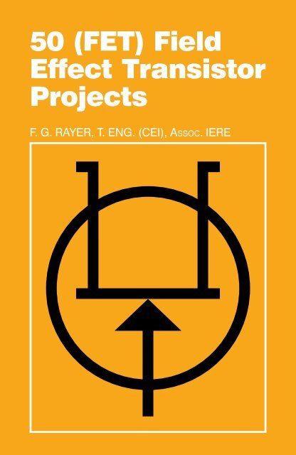
INTRODUCTION<strong>Field</strong> effect transistors find application in a wide variety of circuits.The projects described here include radio frequency amplifiersand converters, test equipment and receiver aids, tuners,receivers, mixers and tone controls, as well as various miscellaneousdevices which are useful in the home.It will be found that in general the actual <strong>FET</strong> used is not critical,and many suitable types will perform satisfactorily. The <strong>FET</strong>is a low noise, high gain device with many uses, and the dualgate <strong>FET</strong> is of particular utility for mixer and other applications.This book should be found to contain something of particularinterest for every class of enthusiast - short wave-listener, radioamateur, experimenter, or audio devotee.<strong>FET</strong> OperationFigure 1 will help clarify the working of the field effect transistor.“A” represents the essential elements of the device, whichhas Source lead 5, Gate lead G, and Drain connection D. Thepath for current is from Source to Drain through the semiconductormaterial, this path being termed the channel. With the N-channel<strong>FET</strong>, the carriers are electrons. The Source is connected tonegative of the supply, and Drain to positive.P-type gates are formed on the N-type channel, providing PNjunctions. When these junctions receive reverse bias, areas surroundingthem are emptied of electron carriers. These “depletionareas” reduce the width of the carrier channel as at B. As aresult there is a drop in the passage of current carriers from Sourceto Drain. Increasing the bias causes the depleted regions to extend,and the channel grows smaller, reducing current even further.Eventually the gate can be made so negative that the channelis virtually closed. This is the pinch off region, and current ispractically zero. The current from source to drain, and throughexternal circuit items, can there fore be controlled by adjusting
the gate voltage. Since the gate to channel junction area is reversebiassed gate current is extremely small, and thus the gateinput Impedance is very high. Generally, the gate current is negligible.“C” is the symbol for this <strong>FET</strong>, with S indicating Source (negative),G for Gate, and D for Drain (positive). Such N-channel <strong>FET</strong>sare conveniently operated with a negative ground or source line.“D” is the symbol for a P-channel <strong>FET</strong>. Typical types and leadoutsare shown later.“E” represents an insulated gate <strong>FET</strong>. The gate is insulatedfrom the channel by an extremely thin dielectric so that there isno junction in the way described for “A”. The substrate is P-typematerial with positive hole carriers. When the gate is made negative,positive charges move from the substrate towards the gate,so that the width of the conducting channel reduced, and thusalso the current from drain to source.The gate input impedance is extremely high, as the gate isinsulated, and may in fact be many hundreds of megohms. This
type of <strong>FET</strong> is thus very useful where a high input impedance iswanted.“F” is the symbol for an insulated gate <strong>FET</strong>. The insulated gate<strong>FET</strong> is readily available with two gates, as at “G”. Signal input isto Gate 1, and Gate 2 may be used to control gain, or for theoscillator input when employing the transistor as a mixer.The extremely high gate impedance of the transistor rendersit somewhat liable to damage, and for this reason protected gatetypes are popular. As shown at “H” diodes are provided from thegates to the substrate and source, which are normally joined at“G”. These diodes conduct if more than a few volts potentialshould arise between gate and source circuits, and this preventsdestruction of the gate insulation, which would make the deviceuseless. Generally the protective diodes shown at “H” are omittedfrom the symbol of a protected insulated gate <strong>FET</strong>.Using <strong>FET</strong>sSoldering precautions which are employed with the bipolarjunction transistor will also avoid damage to the <strong>FET</strong> from heating.The essential is to avoid lengthy cooking of the joint near tothe transistor. If the iron has obtained its correct heat, and surfacesto be soldered are clean, it is generally necessary only toapply the iron and solder for two or three seconds, and in the socircumstances no heat sink clips or similar precautions are necessary.Remove the iron as soon as the joint is properly formed.It will often prove helpful to identify leads by colour coding,especially when using J<strong>FET</strong>s with different lead positions. Withthe usual N-channel <strong>FET</strong> “C” (Figure 1) it is convenient to place ashort piece of black sleeeving on the source lead, with red on thedrain. These indications will then also agree with circuit polarity.The gate can be left bare. With devices having two gates, greencan be used for Gate 1, and blue for Gate 2, or as wished. Suchcoding will also greatly simplify checking connections when the<strong>FET</strong> has been wired into position.
The reference number following each <strong>FET</strong> shows that it hasleads identified from the positions as in Figure 2.<strong>FET</strong> TestingTests which will show whether or not a field effect transistor isin working condition are readily made with a circuit which can behooked up in a few minutes and operated from a 9v battery. Thiscan be useful when dealing with surplus or other <strong>FET</strong>s of doubtfulorigin, or as a test for the <strong>FET</strong> in a circuit which does not function.It can usually be assumed that a new <strong>FET</strong>, purchased from areliable source, will be in working order.Two meters are required to show the relationship between gatevoltage and drain current with the minimum difficulty. Any ordinaryvoltmeter with a scale of about 0-10v, 0-5v, or less, will besatisfactory, and it need not be an expensive meter with highresistance. A milliammeter reading about 0-10mA is also necessary.Single range meters, or multirange test meters on suitableranges, can be used. In Figure 3, M1 is the voltmeter, and M2 themeter to show drain current. The potentiometers VR1 and VR2are in no way critical, but can best be about <strong>50</strong>0 ohm or 1k linear
Type No.BaseMaximumRatingsOther Information2N38191200mW 25vGeneral purpose AFand RF. N-channel.2N5457/MPF 1032310mW 25vGeneral purpose AF.N-channel.2N54581MPF1042200mW 25vGeneral purpose AFand RF. N-channel.2N5459/MPF1052BF2441200mW 25vVHF. N-channel.7644/BF2445200mW 25vVHF. N-channel.(Sub. lead omitted)MPF 1022200mW 25vVHF. N-channel.2N54<strong>50</strong>/53310mW 25vGeneral purpose AF.P-channel.40602/MEM6184330mW 20vDual-gate VHF amp.and mixer.406734330mW 20vDual-gate VHF amp.and mixer.2N38235300mW 30vVHF amp./mixer.N-channel.2N2497/<strong>50</strong>06<strong>50</strong>0mW -Low noise.P-channel.801117100mW 20vRF amp. N-channel.components. VR2 ought not to be over 1k, as source currentpasses through part of the element, so there would be a substantialvoltage drop here for other than low source-drain currentlevels.
With M1 connected as in Figure 3, and VR2 set so that thesource is at 1v above negative, the gate/source potential will bezero when VR1 is also set so that M1 reads 1v. If VR1 is nowadjusted so that M1 shows less than lv, the gate is negative relativeto the source, and the current shown by M2 fails. On theother hand, making the gate more positive causes the drain currentto rise.The relationship between gate and source voltages is readilyshown by connecting the voltmeter at M3. A centre zero 1-0-1vinstrument is ideal here, but an ordinary meter is suitable, withthe leads to it reversed when the gate is more negative than thesource.A typical general purpose <strong>FET</strong> gave the following readings:Gate/Source VoltageDrain Current0.4 negative 1.6mA0.2 negative 2.2mA0 3mA0.2 positive 3.8mA0.4 positive 5mA
Thus, over this range, a change of 0.8v in gate voltage hascaused a change of 3.4mA in drain current.Exact results will depend on the individual transistor and othercircumstances, but the control of drain current by the gate voltagein this way will be absent with a faulty <strong>FET</strong>.
RF AMPLIFIERS AND CONVERTERS144MHz PreamplifierThis preamplifier can be used with existing 2 metre equipment,or ahead of the 144MHz converter described later. TR1 is the40602 or 40673.Aerial input is to a tapping on L1, and will generally be byco-axial feeder. In some circumstances a short vertical aerial orwhip may be used and may provide sufficient signal strength. Ahigh aerial will naturally increase range and many different typesof aerial for 2m reception can be obtained. Alternatively, if a startis being made on this band, a simple dipole may be constructed.This can be self supporting, or of stout wire, and can be about38½in in length overall, with the feeder descending from the centre.Such an aerial will have little directivlty so need not be rotated,and can be raised on a light pole or mast.For 144-146MHz reception, L1 is permanently tuned to about145MHz by T1. Input is to gate 1, from a second tapping, and R3with the by-pass capacitor C2 provide source bias. Gate 2 is operatedat a fixed potential derived from the divider R1/R2. Outputfrom TR1 drain is to the tapping on L2, which is tuned by T2. Fora narrow range of frequencies such as the 2m Amateur band,variable tuning is not justified, especially as L1 and L2 do nottune sharply L3 couples to the existing 2m equipment - generallya converter working into a lower frequency receiver.L1 is wound with 18swg or similar stout wire, enamelled ortinned copper. It has five turns and is tapped at one turn from theupper end in Figure 4 for G1, and two turns from the groundedend for the aerial. The winding is 5/16th in in diameter and turnsare spaced so that the coil is ½in long. L2 is wound in the sameway with five turns, but is ¾in long and has a centre tap for thedrain. L3 consists of a single turn of insulated wire, wound overthe lower end of L2.
When building VHF units of this and similar type, a layout permittingshort radio frequency and by-pass return connections willbe required, and Figure 4B shows a layout for Figure 4. (Notethat TR1 is shown from the top.) A printed circuit can be preparedto take the components, or plain perforated board (0.15inmatrix) can be used, wired below. It is convenient to insert pins totake L1 and L2. A small aluminium box will house the amplifier,and this allows the co-axial aerial and output sockets to bemounted as shown.The screen to divide the box into two sections, to separategate 1 and drain coils, can generally be omitted as the layoutdoes not allow much feedback from L2 to L1. Tapping Gate 1and drain down L1 and L2 also contributes to stability.A 12v supply is preferred, but this can be 9v if other equipmentprovides this voltage and is also to supply the amplifier. Theamplifier can be self-contained if a battery is included in the box,with on-off switch in series.
The bolts MC pass through the board and box, so that theycan provide a ground return, and they require spacers or locknuts. (Should it be felt that full details of preparing a printed circuit,or wiring on perforated board, are required, reference canbe made to handbooks No. BP30 and No. BP35, Babani Press.)Should a resonant dipper be available, or be constructed asshown later, this will allow L1 and L2 to be set to about 145MHz.If the coils are made exactly as described, adjustment of T1 andT2 should give resonance in the 2m band. However, slightchanges in the length of leads, and similar points which arise inconstruction, can influence the frequency. So should either trimmer,be fully open, stretch the associated coil slightly to separateits turns. On the other hand, if either trimmer is fully closed, compressthe coils to bring the turns nearer together. It is possible toexperiment with the taps, for best individual results, if the coilsare wound with tinned copper wire. Resonance can later bechecked when signals are being received through the amplifier.To do this, or tune with no dipper, adjust the trimmers (and coils ifnecessary as mentioned) for best volume.
FM BoosterFor long distance reception, or in areas of low signal strength,VHF FM reception can be improved by using a booster orpreamplifier. Circuits such as those shown for 70MHz or 144MHzmay be adapted for this purpose. However, a circuit which is intendedfor a narrow band of frequencies (such as about 70-71MHz, or 144-146MHz) is only suitable when it is to be set up fortransmissions near in frequency to each other. For a wide bandsuch as approximately 88-108MHz, efficiency falls off too muchat frequencies far removed from that to which the amplifier istuned.The circuit in Figure 5 has variable tuning for the drain coil,and to avoid complication the less important aerial circuit, whichin any case tunes flatly, is broad banded.L2 has four turns of 18swg wire on a powdered, iron VHF coreand is approximately 7mm diameter. L1 is overwound, and hasthree turns, also 18swg L3 is air cored, and consists of four turnsof 18swg wire, wound on an air cored former 8mm in diameter or
5/16th in, with turns separated by the wire diameter. The draintapping is three turns from the grounded end of the coil. L4 is oneturn, overwound on the grounded end of L3. C4 may be substitutedby an air spaced trimmer, to allow more adjustment to coverage.Values are chosen for a BFW10, which is a low noise, widebandVHF amplifier. Other VHF transistors can be used. A separatebattery supply will generally be used, though provision can ofcourse be made to draw power from the existing equipment. Theaerial feeder is plugged into the socket connected to L1, and ashort feeder from L4 is run to the receiver aerial socket. With areceiver having only a whip aerial, connections will have to bearranged for L4.When using VHF amplifiers, it will be found that tuning is relativelyflat, especially where circuits are heavily loaded, as with theaerial inductor. Despite this, a broad peak giving best receptionshould be found. It will also be found that the gain provided bysuch amplifiers is less great than with lower frequency RF amplifiers,and falls off as frequency rises. This is caused by circuitlosses, as well as limitations of the transistors themselves. Capacitorsshould be tubular and disc ceramic, or other types suitablefor VHF, and where inductors have solid cores, these mustbe of VHF type material.70MHz RF StageThis is primarily intended for 4m amateur band use, and has agrounded gate <strong>FET</strong>, Figure 6. A grounded gate stage of this typeis particularly stable, and no isolation other than that provided bya layout similar to Figure 4B is required, to avoid oscillation. Thegain obtained is less than with a grounded source stage. Thetuning of L2 is particularly flat.R1, with the by-pass capacitor C1, is for source bias, and mustbe tapped down L2 as the input impedance of TR1 is low withthis circuit. It is possible to obtain a slight improvement in results
y tapping the drain down L3. The supply can be 9v to 12v, andcan generally be from the equipment with which the stage is used.L2 and L3 could be tuned by trimmers, and be air cored. However,solid cores suitable for 70MHz are easily obtained, so C2and C3 may be fixed, resonance being obtained by adjustmentto the cores then employed with L2 and L3.L2 and L3 each have ten turns, of 26swg enamelled wire, sideby side on 3/16th in diameter (or 4mm to 5mm) cored formers.L1 is overwound on the grounded end of L2, or tightly coupled toit, and has three turns. L4 has two turns, similarly coupled.TR1 is a VHF type transistor with an upper frequency limit of atleast 200MHz. The BF244, MPF102, and similar types can beused. For best possible results with individual samples, R1 andthe tap on L2 can be modified, but are not critical.This circuit is readily adapted for 144MHz use. Self supportingair cored coils, with parallel 10pF trimmers, can then be fitted. L1/L2 can be five turns in all, of 20swg wire, wound to have an outsidediameter of 8mm, and with turns spaced so that the coil is10mm long. A tap for the aerial connection is one-and-a-half turns
from the grounded and of L2, and the source tap (C1, R1) it twoturns from the grounded end. L3 is similarly wound. The drainlead can now be tapped to L3, three turns from the C4 end of thiswinding. L4 is a single turn of insulated wire, closely over L3.As mentioned, the grounded gate stage will not be found toincrease signal strength to the extent obtainable with circuits asFigure 4, but it has the merit of simplicity, or for isolation from theaerial.Medium Frequency AmplifierThis circuit, Figure 7, is primarily intended for use over the1.7MHz to 30MHz range, and will be found to provide considerablegain. RF amplifiers of this kind are generally used to improvelong distance short wave reception, to increase volume,and to reduce second channel interference on the higher frequencies.To avoid winding coils and permit easy band changing, Denco(Clacton) miniature plug in coils may be used. These are they“Blue” (Aerial) ranges, valve type. The most useful coils will be
Range 3, 1.67-5.3MHz, or 580 to 194 metres; Range 4, 5-15MHzor 60 to 20 metres; and Range 5, 10.5-31.5MHz, or 28 to 9.5metres. Exact coverage depends on the setting of the adjustablecores, and will also be modified if VC1 is of different value. Thecoils are inserted in a B9A type holder. If only single range iswanted, the coil can be mounted by its threaded end, and leadsare then soldered directly to the pins.VR1 is an adjustable aerial input control, as overloading mayeasily arise with strong signals. R1 and R2 provide the voltage forgate 2, and R3 is for source bias.The drain circuit is arranged for capacitor coupling by C4 tothe aerial socket of the receiver. This lead should not be unnecessarilylong, as this may cause losses, as well as picking upsignals which cause second channel interference. If the lead isscreened, it must be no longer than necessary. A 2.6mH shortwave sectionalised radio frequency choke will be satisfactory forthe frequencies mentioned.Construction is best in a metal case, which can have a hingedlid if plug-in coils are to be fitted. (An alternative, for several bands,is to use switching as shown for Figure 11.) No ganging difficultiescan arise with VC1, which is adjusted for best volume.Second channel interference is caused by signals which are2xIF frequency from the wanted signals. With a 470kHz intermediatefrequency, these offending signals will be 940kHz from thewanted transmission. As a result, interference from this cause isunlikely at low frequencies, but very probable at high frequencies.Such second channel interference is considerably reduced,or completely avoided, by using a tuned RF stage of this kind,actual results in this direction depending on the receiver IF, andfrequencies tuned.A 9v supply is adequate, and current may be drawn from thereceiver if convenient. Only about 2mA to 3mA or so will be wanted.The MEM618, 40602, and 40673 will be found satisfactory here.
Top Band PreselectorThe 160 metre band carries amateur and other signals, andFigure 8 is a preselector for approximately 1.8MHz to 2.0MHz.Here, VC1/2 is a 2-gang capacitor, and thus two additional tunedcircuits are obtained ahead of the receiver. It is necessary to tapthe gate of TR1 down L2, to preserve stability. However, screenedcoils are not essential, if L1/L2, and L3/L4 are situated at oppositesides of the ganged capacitor and arranged to avoid unnecessaryfeedback or coupling.C1 and C3 are best 2% or similar silver mica. All HF and generalpurpose <strong>FET</strong>s suitable for RF use should prove suitable here.Values ale for the 2N5459 but will suit similar devices. Both coilsare wound on cored formers approximately 10mm or 3/8in indiameter, and using 32swg enamelled wire. L2 and L3 each consistof fifty turns, side by side. Begin winding near the top of theformer, securing the wire with “Bostik 1” or similar adhesive. Thewhole winding should not be covered with adhesive, varnish, waxor other substances. L1 is twenty turns, wound near the bottomof L2. L4 is similarly positioned, but has fifteen turns. It will coupleinto the usual dipole or similar receiver input socket, having anominal impedance of about 75 to 300 ohms. Touches of adhesivewill also hold these turns in position.
A metal cabinet about 6 x 4 x 4 in is suitable for this unit. TR1and R1/C2 can be wired on a small insulated board, fitted adjacentto VC1/2. C1, C3 and C4 can be soldered directly to the coiltags. Separate trimmers for T1 and T2 are only required if theganged capacitor does not have trimmers incorporated. ThoughVC 1/2 provides some bandspread a small bail drive or similarreduction drive should be fitted.13-30MHz Grounded Gate StageIf a receiver has an intermediate frequency of 455 to 470kHz,second channel interference is always present at frequencieshigher than about 15MHz, unless one or more tuned RF stagesare included. This trouble arises because the second channel isso close to the wanted frequency. As example, if the receiver istuned to 20MHz, or 20,000kHz, and the receiver IF is 470kHz,then the oscillator will be operating on 20,000 plus 470 =20,470kHz. However, unwanted signals which are 470kHz higherin frequency than the oscillator will also be converted to 470kHz.As a result, transmissions around 20,940kHz or 20,94MHz will bepassed through the receiver, in this instance, as the aerial circuitwill not reject these, when tuned to 20MHz. This effect, with a
superhet, can only be avoided by raising the intermediate frequency,or providing additional selectivity before the mixer or frequencychanger. The grounded gate stage in Figure 9 introduces two additionaltuned circuits before the mixer, so is of considerable aid inreducing interference from second channel signals. By keepingparallel capacitances to a low value, approximately 30MHz to13MHz can be tuned in a single band, with good efficiency.L2 and L3 are identical, and are wound with 24swg enamelledwire, using 7mm formers with adjustable cores. The cores must besuitable for use at 30MHz or higher frequencies. L2 and L3 areeach eighteen turns, but L2 is tapped at three turns from thegrounded end for C1 and R1. Begin winding from near the topends of the formers, securing the wire with a spot of adhesive.Turns are side by side. L1 is wound immediately below the groundedend of L2, and has seven turns. L4 is wound at the grounded endof L3, and has five turns.Layout should place L1/L2 at one side of the ganged tuningcapacitor VC1/VC2, and L3/L4 at the other side. The output leadfrom L4 and ground line are connected to the aerial terminal andchassis or earth of the receiver. It may be possible to draw a positivesupply from the receiver, 9v to 12v being required here.No connection must ever be made to the chassis of an AC/DCtype receiver which draws current directly from the mains, and maythus have a live chassis.To obtain maximum band coverage without increasing VC1/2 invalue, T1 and T2 must be set at low values. First unscrew T1 andT2 completely. Set the cores of L2 and L3 in approximately similarpositions. A signal should then be tuned in around 28-30MHz, andT1 or T2 can then be adjusted for best volume. Subsequently finda stable signal around 14-16MHz, and set the cores for best volume.These adjustments should be repeated a few times, adjustingT1 and T2 at the HF end of the band (VC1/2 nearly fully open)and the coil core towards the LF end of the band (VC1/2 nearlyclosed).
It the receiver has a signal strength or tuning meter, this willaid critical alignment. Alternatively, choose weak signals or if possibleswitch off the automatic volume control circuits, so that AVCaction does not mask adjustments.Should a receiver with no RF stage be in use, check that thegrounded gate stage is actually being tuned to the correct signalfrequency, and not to the second channel, as second channelsignals may come through strongly with such a receiver.With receivers having an IF of 1.6MHz, the second channelwill fall at 3.2MHz from wanted transmissions, so is less likely tobe troublesome.11-32MHz MOS<strong>FET</strong> StageThis can have similar applications to the circuit in Figure 9, butuses a dual gate <strong>FET</strong>, Figure 10. Such a stage can provide a veryuseful degree of gain. It becomes necessary to screen or segregategate 1 input and drain output tuned circuits.L2 and L3 each have eleven turns of 26swg enamelled wire,
side by side on a 7mm cored former. With a 2-gang 100pF capacitorfor VC1/VC2, coverage is approximately 11 to 32MHz.Trimmer T1 and T2 can each be 20pF.The coils are wound as described for Figure 9, and alignmentof the two tuned circuits is also carried as described there. L1 hasfive turns, and L4 four turns, situated as explained for Figure 9.TR1 operates with fixed gain. If a gain or sensitivity control iswanted, this can be added as shown in other circuits. An aerialinput potentiometer may be added (Figure 7) or gate 2 voltagecan be adjusted by a potentiometer.A gain control is not likely to be necessary when the stage isused before a receiver which has its own RF gain control. Otherwise,overloading of early stages of the receiver may arise withstrong signals.Alternative forms of output coupling are shown. If L4 is used,one end is grounded (see Figure 9) and Y is connected to theaerial input socket of the receiver. This method is preferred wherethe receiver has the usual medium or low impedance input. Somereceiver have a high impedance aerial socket for end fed andsimilar aerials which are arranged for high impedance feed, andwith these results will be improved by not using L4, instead, C4provides capacity coupling to the aerial socket at X. Trimmingand alignment of L2 and L3 should be checked after adding thisconnection and C4.The 40602 or 40673 will perform well here, though other dualgate <strong>FET</strong>s can be fitted with satisfactory results.Segregation of circuits is most easily achieved by using a smallmetal chassis, with L1/L2 on top, near VC1/2. A lead can thenpass down through the chassis from VC1 to G1. TR1 and associateditems, including L3/L4, can be under the chassis. Thisscreens L3 from L2. The RF connection from X or Y to the receivershould be short, and away from the aerial lead to L1.
Ham Band PreselectorAn amplifier or preselector is often used to improve the receptionof amateur signals. By employing a selection of series andparallel capacitors, it is possible to arrange that each band shallcompletely fill the tuning scale. However, this does not contributeanything in terms of efficiency, and can be tiresome to adjust. Forthese reasons, tuning here is with the single capacitor VC1, withparallel fixed capacitor C2. Values are chosen to accommodatethe largest band, so there is coverage to spare on the smallerbands. This is of little or no disadvantage in practice, since tuningof the preselector is merely to peak up the wanted signals in eachband.The amateur bands are as follows: 1.8-2.0MHz (160 metres),3.5-3.8MHz (80 metres), 7.0-7.1MHz (40 metres), 14.0-14.35MHz(20 metres), 21.0-21.45MHz (15 metres), 28.0-29.7MHz (10 metres).Outside Great Britain some of these frequencies are extended.
In Figure 11, a 2-pole 6-way switch selects the required coils,for 160, 80, 40m and other bands. Signal input is to gate 1. Thepotentiometer VR1 provides a gain control, to avoid over-loadingof the receiver with strong signals. Drain and source circuits arearranged as in Figure 7, with capacitor coupling to the receiver. Ifthe drain circuit were also tuned, twelve coils would become necessary,with ganged tuning.Winding of the six aerial coils is not too critical, as it is onlynecessary to set the cores so that amateur signals throughouteach band can be peaked by VC1. All coils are wound on formersapproximately 9/32in or 7 mm in diameter, and 1in long.10m. Seven turns 26swg side by side.Aerial coupling four turns.15m. Nine turns 26swg side by side.Aerial coupling five turns.20m. Fifteen turns 32swg side by side.Aerial coupling eight turns.40m. Twenty eight turns 32swg side by side.Aerial coupling fifteen turns.80m. Sixty turns 34swg side by side withtwo cores.Aerial coupling thirty five turns.160m. 120 turns in compact pile occupying¼in width, 34swg.Aerial coupling 60 turns in pile.Details of coil winding will be found earlier. It is important thatwindings are not covered with adhesive, cement, or other substances.Winding should begin very near the top of the formers,to give clearance from a metal chassis if inductors are mountedon it. At least one winding diameter should be left between anymetal and the coil (say ½in minimum).Layout should place the switch near VC1 and G1, and shouldpermit very short connections for 10m, 15m and 20m coils in particular.
In view of the number of turns required for 160m, it may benoted that a receiver type medium wave band coil can often beused here. Some coils of this type will reach 160m with the corescrewed fairly well out. If not, some turns need to be removed.A Litz wound coil here will give some improvement in efficiency.<strong>Portable</strong> Receiver BoosterThe range or volume of a domestic portable receiver can beincreased considerably by adding an external aerial, and the circuitin Figure 12 does this, and provides a tuned booster stagealso. With an external aerial, this can allow a small transistor portableor similar receiver to give good reception of signals whichmay be virtually inaudible otherwise. The booster is not requiredfor normal or local reception, and it is not permanently connectedto the receiver in any way.Medium Wave coverage is most useful, and the coil connectionnumbers are for the Denco (Clacton) “Blue” Range 2 valvetype coil. This can be fitted in a 9-pin valveholder, or can bemounted by its threaded end, with leads soldered directly to thepins. Coverage in this circuit is approximately 1.6MHz to 5<strong>50</strong>kHz,but can be varied to suit the receiver by altering the position ofthe coil core.
A converter of this type often has its own RF amplifier, and arelatively low frequency crystal controlled oscillator, followed byfrequency multipliers. This allows high sensitivity and excellentfrequency stability, but is a relatively complicated and expensiveitem. Bearing in mind that at this frequency the RF amplifier willnot, contribute very much gain, and that tunable VHF oscillatorsare used in many domestic VHF receivers, it is possible to usethe much simpler circuit in Figure 13.L1 is broadly tuned to the wanted frequency band by T1, andsignal input is to gate 1 of TR1. TR2 is the local oscillator, and theoperating frequency here is determined by L2 and T2. Oscillatorinjection is via C3 to gate 2 of TR1. The frequency of the outputfrom the drain of the mixer TR1 is the difference between G1 andG2 frequencies. Thus if the signal at G1 is 144MHz, and TR2 istuned to oscillate at 116MHz, output will be at 144 minus 116MHz,or 28MHz. Similarly, with the oscillator set at 116MHz, an input at146MHz to G1 will give an output of 30MHz. Therefore 144-146MHz can be covered by tuning the receiver from 28MHz to30MHz. L3 is broadly tuned to this band, and L4 couples thesignal to the short wave receiver.The oscillator can actually be tuned above or below the aerialcircuit frequency of the converter, as it is the difference betweenconverter signal input and oscillator frequencies which determinesthe converter output frequency. It is also possible to choose otherreception and output frequencies, provided L1, L2 and L3 arechosen to suit.L1 and L2 are wound in the same way, except that L1 is tappedone turn from its grounded end. Each coil has five turns of 18swgwire, self supporting, formed by winding the turns on an object7mm in diameter. Space turns so that each coil is ½in or about12mm long.L3 is fifteen turns of 26swg enamelled wire, side by side on a7mm former with adjustable core. L4 is four turns, overwound onthe earthed (positive line) end of L3.
Layout should allow very short connections in the VHF circuits.A co-axial aerial socket is fitted near L1. A screened coaxiallead is preferred from L4 to the receiver, to avoid unnecessarypick-up of signals in, the 28-30MHz range. The converter willoperate from a 9v to 12v supply.L3 should first be peaked at about 29MHz. If a signal generatoris available (that described later can be used) couple this toTR1 drain by placing the output lead near the drain circuit. Tunegenerator and receiver to 29MHz, and adjust the core of L3 forbest results. Otherwise, couple an aerial by means of a smallcapacitor to the drain circuit, and tune in some signal in the 28-30MHz range, to allow adjustment of the core of L3.It is now necessary to tune L1 to about 145MHz, and L2 to116MHz, or 174MHz. If an absorption frequency indicator is available,this will permit an approximate setting of T2. A dip oscillatorwill also allow T1 to be adjusted. (The circuits shown later may beused here.) Subsequently adjust L2 to bring the wanted signalsin at the required frequencies on the receiver, and peak these forbest volume with T1, and check the setting of L2 core.The converter is best assembled in a small aluminium box,completely closed, which can be placed behind the receiver. Notethat if TR2 is not oscillating, no reception is possible through theconverter. TR2 should be a VHF <strong>FET</strong>, such as the BF244, MPF102,and similar types, and if necessary T3 may be adjusted to secureoscillation here. The 40602, 40673, and similar VHF types will besatisfactory for TR1. If needed, frequencies can be brought withinthe swing of T1 and T2 by stretching or compressing L1 or L2.The aerial may be about 38½in long, constructed as a simpleself-supporting or wire dipole, with a feeder descending to theconverter.Amateur activity is most likely to be greatest at week ends,and in many areas a whip or very short wire aerial will providelocal reception.
S.W. Tuning ConverterThis converter allows short wave reception with a receiverhaving a medium wave range which can be tuned to about1.4MHz to 1.6MHz, or 1400-1600kHz. It has a single range, coveringapproximately 5 to 15MHz, or 60 to 20 metres, and thisincludes the most important short wave broadcast bands.Two transistors are used, Figure 14. TR1 is the mixer, and TR2the oscillator. Tuning is by the ganged capacitor VC1/2, and outputat a fixed frequency in the 1.4-1.6MHz range passes to thereceiver from TR1 drain at X.L1 numbering is for the Denco (Clacton) “Blue” Range 4 aerialcoil, L4 being the “White” (1.6MHz IF oscillator) Range 4 coil.Both are valve type coils. C4 is the oscillator padder, and it will befound that 960pF, 970pF or 1000pF may be used, though 960pFis specified by the coil maker.Trimmers T1 and T2 can be integral with the ganged capacitorVC1/2, or may be separate trimmers of about <strong>50</strong>pF.It is convenient to use a layout in which L1 and TR1 are nearthe front section of the tuning, capacitor. VC1. L2 and TR2, withassociated items, can then be adjacent to the rear section, VC2.One of several possible methods can be used to couple thedrain of TR1 to the receiver. A radio frequency choke between Xand the positive line will allow capacitor coupling, as in Figure 7.It is also feasible to provide a coupling winding on the receiverferrite rod, as in Figure 12, or use an existing external aerial couplingwinding here, in some receivers. A resonant coupling, as inFigure 13, is also practicable, this being arranged for the frequencyto be used with the receiver. This should not be too far removedfrom 1.6MHz or 1600kHz, or alignment difficulties can arise in theconverter. If the receiver is of the type which must have an externalaerial, it should not be too difficult to find a frequency near thehigh frequency end of the MW band where no unwanted signals
eak through. More care in finding a frequency may be necessarywith a portable receiver with ferrite aerial, especially duringthe hours of darkness.When a tuning position has been found on the receiver whichgives no reception, note this for future use. Switch on the converterand align aerial and oscillator circuits in the usual way.The low frequency band end reached depends largely on theposition of the core of L2, while the high frequency band enddepends on T2. Initially set L2 core at about middle position; withT2 about half open. L1 and T1 must then be adjusted for bestreception. L1 core is always adjusted near the LF end of the range,and T1 near the HF end. That is, rotate L1 core for maximumvolume with VC1/2 nearly closed, and set T1 with VC1/2 nearlyfully open.Should L2 or T2 be altered, to modify the band tuned, then L1and T1 will have to be readjusted to match.If wished, T1 may be omitted, and a <strong>50</strong>pF panel trimmer canbe used instead. This will allow signals to be peaked up criticallywith any aerial, and eases alignment of aerial and oscillator stages.With an RF amplifier having two tuned circuits (as example,Figure 10) both coils must tune simultaneously to the same frequency.But in Figure 14 L1 and L2 must maintain a frequencydifference throughout the tuning range, this corresponding to theoutput frequency at X. As example, if the output is to be 1.6MHz,and L1 is tuned to 10MHz, then L2 is tuned to 11.6MHz. As far aspossible, this same frequency difference should be maintainedfor all tuning positions of VC1/2. This is achieved by L2 being oflower inductance than L1, and by the series padder C4.
TEST EQUIPMENT AND RECEIVER AIDSThis section contains a selection of units which will be foundof use when aligning or testing receivers and other circuits, or forreceiver calibration, frequency checking, or reception of sidebandand Morse, as well as checking the output of oscillators or transmittingequipment.RF Signal GeneratorA signal generator is a most useful instrument for aligning andchecking the RF and IF sections of a receiver. Figure 15 showsthe RF section of a generator, to which modulation can be addedas explained later.L1 and VC1 can be selected from a wide range of values, tosecure the coverage required. It is convenient to fit the Denco(Clacton) “Red” oscillator coils, of valve type. With these, pin 8 istaken to drain (S1) and pin 9 to C1. Pin 1 goes to S2 for all coilsexcept Range 1, when pin 7 is used. The appropriate ground pin
for each range is as shown below, which indicates the bandsover which these coils can be used, with a capacitance swing ofapproximately 20-3<strong>50</strong>pF for VC1.Range 1. ( 5 ) 380 - 1600kHz.Range 2. ( 2 ) 0.8 - 3.5MHz.Range 3. ( 3) 2 - 8.5MHz.Range 4. ( 4 ) 6 - 22MHz.Range 5. ( 6) 15 - 45MHz.If other coils are used, allowance has to be made for the omissionof the usual padders and trimmers, as well as for the differencein receiver aerial and oscillator frequencies.S1/S2 can have as many ways as bands required. However,the higher frequency coils need short connections, and coils mustbe reasonably separated from each other. Numerous generalpurpose and RF type <strong>FET</strong>s will be found suitable. The presenceof oscillation throughout each band can be checked with a meterin one battery lead - current should change if VC1 is shorted.The drain feedback winding must be correctly phased to obtainoscillation.VR1 is an output attenuator. Construction should be in a metalcabinet, with a reasonably large scale for VC1. Calibration canbe by the methods described later.The signal produced by this generator is unmodulated, or silent.Unmodulated RF is used for tuning sharp crystal filters, andcan be used for alignment of receivers which have a tuning meteror indicator, or where a meter is clipped to the AVC circuit toshow the effect of adjustments. For other purposes, it is necessarythat an audio tone is present with the carrier or RF signal.Modulated RF GeneratorAdding T1, TR2 and associated items, shown in Figure 16, willallow modulation of the RF signal produced by the generator.
The first stage in Figure 16 consists of the RF generator, as inFigure 15.TR2 is an audio oscillator, with feedback from drain to gate bymeans of the transformer windings. A small driver transformer, asused to couple the driver stage to ½-watt and similar push-pulloutput stages in transistor portable and other receivers, will befound suitable for T1. The original primary is used for the draincircuit. The whole of the secondary is employed for the gate, thecentre-tap being ignored. If no oscillation is secured, reverse theconnections to one winding. It will be found that considerablecontrol over the tone produced can be exercised by the choiceof values for R1, R2 and C1. A clear tone of middle frequency(say 400 hertz) is most satisfactory. TR2 is a general purpose oraudio <strong>FET</strong>.The RF produced by TR1 will now be heard to carry an audiotone, so can be tuned in by ear with a receiver. For trimming andsimilar adjustments, take the generator output to the aerial circuitof the receiver, or to a loop of a few turns near or on its ferrite rod.Signal level must be kept down with VR1, or the receiver automaticvolume control response will mask exact adjustments.RF CalibrationIf a wide range, correctly calibrated receiver can be used, simplycalibrate the generator scales by tuning in the generator signal.Note that harmonics of the generator frequency will be heardwith the receiver. These are multiples. As example, if the generatoris tuned to 1MHz, it will be heard also on 2MHz, 3MHz, andhigher multiples, these growing progressively weaker. This cancause errors if not watched, but can be useful in allowing calibrationof the generator at frequencies not available on the receiver.If an accurately calibrated receiver is not available, very exactcalibration points can be obtained with a harmonic marker, describedlater.
Any audio or general purpose <strong>FET</strong> can be fitted. Sensitivity toweak audio signals can be raised by adding source bias this canbe a 2.2k resistor with 47uF parallel capacitor. Over-loading orexcess volume with powerful signals can be avoided by replacingR1 with a <strong>50</strong>0k potentiometer, taking the gate to its wiper. Thewhole unit can conveniently be made in a small box, to hold inthe hand, with output socket for headphones or a single earpiece.Audio OscillatorThe circuit in Figure 18 may be used to generate an audiotone for audio circuit tests, or may be used instead of TR2 inFigure 16. An output type audio transformer is used, of the typeintended for ½ watt and similar output stages. The Radio-sparesT/T7, which has a ratio of 9.2 (centre tapped): 1 will be foundsuitable.Tone and output can be altered by changing any of thecornponent values, or by including a source resistor of 1k to 2.7kor so.
Output is for testing amplifiers or other audio circuits, can befrom an isolating capacitor C3 of about 10nF. An attenuated outputcan be obtained by adding a potentiometer, with output fromthe wiper via a capacitor.To test audio circuits with such an oscillator, begin at the outputstage or latest point where a signal is produced in the loudspeaker.Work backwards systematically, taking the audio toneto coupling transformer or capacitor, driver stage, and so on. Whenthe tone is no longer heard, the item last introduced into circuit isfaulty. This may be a simple component failure; or may dependon associated items, where a whole stage fails to operate. However,relatively few items will need detailed testing.Any general purpose audio <strong>FET</strong> is suitable, and a supply of 6vwill be adequate. If required, connections to the secondary of T1can be made, for low impedance tests such as of speakers.Capacitance BridgeOne of the <strong>FET</strong> oscillator circuits described is convenient toprovide audio for a capacitance bridge. The <strong>FET</strong> oscillator in Figure19 can be built as described for Figure 16. The source resistorand capacitor can be chosen so that a strong, fairly highpitched tone is produced. Best values will depend on the <strong>FET</strong>and transformer, but are not critical. For a 2N3819, a 3.3k resistoris suggested, with 0.5uF capacitor. Rather low frequencies areless suitable, as volume will become insufficient when checkingsmall capacitors.Audio output is coupled to the bridge by C1. S1 selects C1,C2 or C3 which together with the unknown capacitor Cx formsone side of the bridge, the other side being upper and lower sectionsof VR1.Values of 100pF for C1, 10.000pF, 10nF or 0.01uF for C2, and1uF for C3 will give wide ranges having centre values of 100pF,10nF and 1uF. VR1 should be a good quality linear potentiometer.
Calibration of its scale can be by placing known values at Cx; orthe scale shown on page 28 of “Two <strong>Transistor</strong> Electronic <strong>Projects</strong>”(Babani Press No. BP30) may be used.High impedance headphones are most suitable for detectingthe audio tone. VR1 is rotated for the null, when the audio signalceases, and the bridge is then balanced, and the value of Cx canbe read off from the scale. When checking capacitors from audiocircuits or other equipment, it should be noted that there is oftenquite a wide latitude in the value, which is not critical. The bridgeis not intended for finding the values of very small capacitors, asthe audio tone grows too weak, and readings are influenced bystray circuit capacitance. This limits the range for the smallestvalues to about 10-20pF. The bridge will be found very useful forchecking the values of unknown or coded components.AF Oscillator ProdThis circuit requires no transformer. It may be constructed in avery small space, if miniature low-voltage capacitors and smallresistors are fitted. The values shown in Figure 20 will be foundsuitable, but can be modified to some extent without too muchchange in the tone produced.
General purpose, audio, and similar <strong>FET</strong>s are suitable. Outputis taken via the isolating capacitor C5. This item need only have ahigh voltage rating if AC mains type equipment will be tested.The safety precaution mentioned earlier must be rememberedwhen dealing with any mains receiver or amplifier.The use of a prod of this type has already been described. It isemployed to inject an audio signal into various points, workingbackwards from the Output stage, until the fault is localised. Thewhole oscillator is readily assembled on a small piece of perforatedboard, with space to accommodate a 9v battery.Amplified Absorption WavemeterA wavemeter is likely to be of use to the amateur who adjustshome built or commercial equipment operating on short waveranges. The circuit in Figure 21 is for operation over 1.8MHz to<strong>50</strong>MHz.The use of the <strong>FET</strong> amplifier avoids the need for a very sensitiveindicating meter, as a 1mA instrument is suitable. In opera-
tion, VC1 tunes the inductor to resonance so that D1 produces apositive voltage across R1, for the <strong>FET</strong> gate. The meter itself is ina bridge circuit, VR1, the <strong>FET</strong> and R2 being one side, and R3/R4the other side. Balance, or zero current through the meter, is obtainedby setting VR1. Balance is then upset when the gate movespositive, and the indication can be half scale or more, so thatgood sensitivity is obtained.With a 100pF capacitor at VC1, four coils will cover the rangementioned. These may all be wound on 1 in diameter paxolintube, using 24swg enamelled wire. In an instrument of this type,plug-in coils are favoured. These will require four octal of similarbases, which may be from old useless valves, with a holder tosuit. With some bases, the two smaller coils can be wound directlyon the base itself, as there is sufficient length available.The smallest coil has two turns, tapped at about one turn forthe diode, and its range is approximately <strong>50</strong>-20MHz. The nextcoil has seven turns, tapped at two turns from the grounded end,and covers 26-10MHz. The next larger coil needs twenty-two turns,tapped at seven turns, and tunes 16-5MHz. The largest coil tunes5.5-1.8MHz, and has seventy turns, tapped at twenty turns.Construction of this type of instrument usually places the coilprojecting from one end of a narrow box, with VC1 adjacent on
the top, which also carries the meter and VR1. It is then easy tohold the device in one hand, with the coil near the source of RF tobe checked, while tuning with the other hand. Four scales can bemarked and placed under the control knob fitted to VC1. With noRF present, set VR1 so that the meter reading is just beginninigto rise from zero. Any general purpose <strong>FET</strong> will operate in thiscircuit.Aperiodic <strong>Field</strong> Strength MeterThe device in Figure 22 will operate at any frequency up to2<strong>50</strong>MHz or even higher if necessary. A short whip, rod, telescopicor other aerial picks up radio frequency energy, and rectificationby diode D1 provides a positive voltage for the <strong>FET</strong> gate, acrossR1. This <strong>FET</strong> is only operating as a DC amplifier, and the 2N3819and other general purpose transistors will be satisfactory.The “Set Zero” potentiometer may be 1k to 10k. With no RFsignal present, it allows gate/source potential to be adjusted sothat the meter shows only a small current, which rises in accordancewith the strength of the RF present. For high sensitivity, a100uA meter can be fitted. Alternatively, a meter of lower sensitivity,such as 25uA, <strong>50</strong>0uA or 1mA can be used, and will provideenough indication in most circumstances.
Should the field strength meter be wanted for VHF only, a VHFchoke can be used, but for general usage over lower frequencies,a short wave choke is necessary. An inductance of about2.5mH is satisfactory for 1.8MHz and higher frequencies.The device can be constructed in a small insulated or metalbox, with the aerial projecting vertically. In use, it allows tuning upa transmitter final amplifier and aerial circuits, or the adjustmentof bias, drive and other factors, to secure maximum radiated output.The effect of adjustments will be shown by the rise or fall ofthe reading of the, field strength meter.Gate DipperFigure 23 shows an extremely simple resonant dip oscillator. Itcan be used over a wide range of frequencies by the use of plugincoils. With such instruments, the coil generally projects at oneend of the case, so that it can be brought near to the inductors ofother tuned circuits.
VC1/2 is a 2-gang capacitor, 100pF each station. Feedbackfrom the <strong>FET</strong> drain by C1 results in oscillation, and rectification inthe gate circuit produces a small current through R1 and VR1.When a tuned circuit under investigation is inductively coupledto the dipper coil, and both are tuned to the same frequency, RFenergy is absorbed. As a result, the current through R1 falls, andthis is shown by a dip in the meter reading. Sensitivity is controlledby the setting of VR1. A <strong>50</strong>uA meter is most satisfactory, asthe dip is small for average degrees of coupling of the dipper tothe tuned circuit being checked. However, this is no particulardisadvantage, as a clear dip is produced, to show resonance.Such an instrument is generally used to check the frequenciesof oscillator, multiplier and power amplifier coils in transmittingequipment, or the frequency of circuits in converters, HF orVHF receivers, and similar apparatus. These tests can be madewith no voltages present on the equipment. To check the frequencyof a circuit, the dipper coil is held near the inductor of thecircuit, and VC1/2 rotated until the dip is seen, showing resonance.The frequency can then be read from the dipper. To set acircuit on frequency, tune the dipper to this, couple it to theinductor, and set the core or trimmer of the latter until the dip isobtained. Initially, it is usual to have dipper and equipment coilsnear each other, for ease in finding the dip. The dipper coil is thenmoved a little away, to loosen coupling, as very tight couplingmay upset frequency readings. Coupling is maximum with theinductors in line, near together, but other angles and positionswill provide coupling.The, dipper coils can be wound on 1 in diameter paxolin tubes,which can have two pins fitted one end, or can be attached tovalve bases from old octal or similar valves. A coil for 3-7MHz canhave 70 turns of 24swg enamelled wire side by side. For 6-16MHz,the winding can be twenty six turns of 24swg enamelled wire,side by side. For 17-46MHz, nine turns of 18swg enamelled wire,side by side, can be used. For these frequencies, a 2.5mH orsimilar RF choke is used. The HF and VHF <strong>FET</strong>s with an upperfrequency limit of 100MHz or higher will be found to work well
here. The upper frequency limit at which the dipper can be useddepends on the RF choke, short leads with low loss construction,and a VHF <strong>FET</strong>. When oscillation ceases, no meter reading isobtainable.Drain Dip OscillatorThis instrument, shown in Figure 24, allows similar tests to thoseobtained with the Gate Dipper, Figure 23. However, the meter Mis now incorporated in a bridge circuit, with R2 and the <strong>FET</strong> onthe positive side, and VR1 and R3 on the negative side. In use,VR1 is set so that M indicates about half scale. Resonance betweenthe dipper coil and a coil in equipment being checkedthen causes a drop in the meter reading.Due to the bridge circuit and fact that this is controlled by thedrain current, the change present to operate the meter is muchlarger than in Figure 23, and it will be found that a 1mA instrumentcan be fitted. With a very sensitive meter, readings can tendto go off the scale too easily, so that frequent adjustment of VR1is needed.
Uses of this instrument are as described for Figure 23. It isconvenient to use a separate on-off switch for the battery circuit,in both dippers, so that the potentiometer can be left set for suitableresults.Crystal MarkersA crystal marker is commonly used by short wave listeners oramateurs to find or check frequency bands, to determine bandlimits, or to provide exact calibration of a receiver or other equipment.In fact, many of the better communications type receivershave such a marker incorporated.The marker uses a crystal oscillator of high frequency accuracy,and it produces a range of harmonics, or multiples, of thisfrequency. As an example of the use of such a marker; assumethat it has a 1MHz crystal. This produces a fundamental frequencyof 1MHz, and harmonic output at 2MHz, 3MHz, 4MHz, and so on.These multiples can normally be detected up to 30MHz or higher,with a communications receiver of normal sensitivity. By countingthese harmonics, at 1MHz intervals, across a waveband, orup or down from any known frequency, a receiver tuning scalecan be checked with great accuracy. This also permits exact calibrationof a home built signal generator, or similar equipment, bytuning the genrator to various marker harmonics, meanwhile calibratingits scales.The circuit in Figure 25 will be found suitable for crystals throughthe 1 MHz to 7MHz range, using a 2.5mH or similar RF choke.With some crystals and <strong>FET</strong>s, C1 and R2 can be omitted, thoughthese help easy working of the circuit.The value of the trimmer is not very significant, but will generallybe around <strong>50</strong>pF or so for 1MHz, 1.8MHz or 3.5MHz crystals,and unscrewed to 15pF or so for 7MHz crystals. No oscillationmay be obtained if the value here is very unsuitable. There isusually no need for a supply of more than 9v.
Coupling from the marker to the receiver is generally not verycritical. For fundamental frequencies or near harmonics, it maybe sufficient to place the marker near the receiver aerial lead. Buthigher harmonics grow progressively weaker, and it is then necessaryto place an insulated lead from C2 near the receiver aeriallead, or plug this connection into the receiver aerial socket.The marker pips are unmodulated RF, so will be found bymeans of the receiver tuning meter, or by switching on the receiverbeat frequency oscillator. (The BFO is a standard adjunctwith a communications receiver, but can be fitted to other receiversas shown later.) The use of 1MHz harmonics, for calibration at1MHz intervals as required, has been described. For amateurband purposes, a 1.75MHz or 3.5MHz crystal may be used. The3.5MHz crystal would give marker pips at 3.5, 7, 14, 21 and 28MHz,as well as at 10.5MHz (3rd harmonic), 17.5MHz (5th harmonic)and other multiples. The latter are far removed from amateur frequencies,and may be ignored, or used to check receiver calibrationgenerally.
Tunable MarkerThe use of a crystal as described for Figure 25 provides highfrequency stability and accuracy. However, it is possible to economiseby using an LC circuit, instead of the crystal. With such acircuit, frequency accuracy is sufficient for general purposes if itis checked before use, and no crystals need be obtained.In Figure 26, C2 and the associated coil will determine thefrequency, which is set by movement of the coil core. Oscillationis obtained by feedback of the drain circuit.Pin numbers shown are for the Denco (Clacton) “Blue” and“Yellow” valve type coils. Should other coils be tried in this, marker,and no oscillation be obtained, reverse connections to the feedbackwinding. A 2N3819 is used.Using a Range 1 coil, C2 is 1000pF, for 100kHz. With this coil,changing C2 to 2<strong>50</strong>pF will allow 200kHz to be reached. For 1MHz,the value of C2 is 82pF, with a Range 2 coil.
Coupling to the receiver can be by placing the aerial lead nearthe coil, or as explained for Figure 25. It may be necessary toremove or reduce coupling from the usual outdoor type aerial, toavoid signal swamping the marker signal.To tune the marker for 100kHz or 200kHz, tune the receiver tothe 200kHz or 1<strong>50</strong>0m BBC transmitter, and adjust the core of thecoil until the heterodyne is heard. Set the core for the zero beatposition. Rotating the core either way will then cause an audiotone which rises in pitch. If C2 is as explained, this will be the 2ndharmonic, or fundamental, according to whether the marker isworking a 100kHz or 200kHz.For the 1MHz setting, tune this as closely as convenient bychoosing a MW signal near this frequency. Then tune the receiverto the standard frequency transmission which will be heard on5MHz. The core is then slightly adjusted, to bring the 5th harmonicinto zero beat with this. Check on the MW band to makesure that the 4th or 6th harmonics are not being heard (12<strong>50</strong>kHzor 833kHz).Use of the tunable marker is as described for the crystal controlleddevices. However, tuning should be checked in the wayjust explained before using the harmonics for frequency calibration.With a little care, frequencies may be obtained with sufficientaccuracy for any general purpose.Signal Frequency SSB/CW ResolverMany general purpose receivers will have frequency bandswhich cover some of the amateur allocations, but which are notable to resolve single sideband or CW (Morse) signals. With acommunications type receiver intended for SSB or CW reception,a beat frequency or carrier oscillator is provided. With its aid,SSB or CW signals can be received. When a general purposereceiver is employed, the BFO or CO can be constructed as aseparate unit.
The output of the BFO or CO may be taken to the intermediatefrequency circuit of the receiver, as shown later. Alternatively, thebeat frequency or carrier oscillator can operate at the frequencyof the band being tuned. If so, no actual connection at all is necessaryto the receiver, as the wanted signal and oscillator signalare both fed into the receiver aerial circuit.This method is convenient for the low frequency amateurbands, especially 1.8-2.0MHz and 3.5-3.8MHz. It also has someadvantage where the receiver tuning control is of a type whichcannot easily provide critical tuning, as the latter will now dependon the signal frequency SSB/CW resolver.The circuit in Figure 27 will operate at a fundamental frequencyof approximately 1.75-2.0MHz, or 3.5-4.0MHz. The former rangeis suitable for both 160m and 80m, as the second harmonic ofthe 160m range will provide resolution on the 80m band. However,the 3.5-4.0MHz coverage is more suitable when 80m aloneis wanted, or some reception on perhaps 7MHz or 14MHz, withharmonics.
For the lower frequency range, C1 is 2<strong>50</strong>pF and VC1 is 75pF.L1 has fifty-seven turns in all, tapped at twelve turns from thegrounded end. The winding is of 32swg enamelled wire, on a 7/16th in or 11mm diameter former, with adjustable core. Turns areside by side. To cover the higher frequency range, L1 has thirtyturns, tapped at 6 turns, with wire and former as described. C1and VC1 are as shown.Stabilisation of the oscillator can be omitted when the currentis to be drawn from a separate battery, but becomes necessary ifthe circuit is operated from the same battery as the receiver. Otherwisefluctuations of supply voltage, especially at other than lowloudspeaker volume, will cause frequency modulation of the oscillator.Construction of the resolver should be in a metal case, withrigid mounting of components. A reduction drive is necessary forVC1.As the output from the oscillator passes into the receiver aerialcircuit, and is amplified with other signals, very loose couplingmust be used. It may be found adequate merely to place theresolver unit near the receiver aerial lead. If more coupling thanthis proves necessary, a lead a few inches long can be takenfrom the tap on L1, out of the screening box, and near to theaerial lead. The, degree of coupling is not too critical. But if this istoo great, signals will be swamped by the oscillator carrier. Alternatively,very loose coupling will give too low an input to the receiver,so that strong SSB or CW cannot be resolved.To operate the unit, tune in the wanted SSB or CW signal withthe receiver. Final tuning is now done with the resolver control, atthe point where the oscillator signal is heard to beat or mix withthe transmission tuned in. With CW, tuning is not too critical, asadjustments around the transmission frequency will merely alterthe audio pitch. But for good reception of SSB, tuning is quitecritical, as the resolver carrier should replace the carrier whichwas suppressed before transmission as correctly as possible.
Tight coupling of the oscillator is not necessary, and shouldnot be made to an aerial, as this could cause interference to nearby listeners.1.6MHz Beat Frequency OscillatorTo resolve SSB or CW, a BFO signal may be coupled into theintermediate frequency amplifier. In these circumstances, the BFOhas to operate near the intermediate frequency of the receiver,for transmissions of all frequencies. So with a BFO of this type,signals may be received at any frequency throughout the rangeswhich are provided for the receiver.Some short wave receivers have an IF of about 1.6MHz. TheBFO must then be constructed for this. With most general purposeor ordinary domestic receivers, the IF is near 455/470k Hz. If so,the BFO has to be arranged with this in view. Except for this pointof providing the correct frequency, both 1.6MHz and 455-470kHzBFO units are the same, and employ the circuit in Figure 28.455-470kHz Beat Frequency OscillatorA general purpose RF <strong>FET</strong> is used as oscillator, Its frequencyis determined by VC1, with the associated winding and parallelcapacitor. The smaller winding is for drain feedback. A stabilisedsupply with 6.2v 400mW Zener diode allows the unit to be runfrom the receiver, if wished.For frequencies around 1.6MHz, a Denco (Clacton) IFT17 intermediatefrequency transformer is used. For frequencies in the455-470kHz range, the IFT14 is fitted. Each has the parallel capacitorpresent inside the screening can, in the usual way, andpin connections are shown in Figure 28.Components may be assembled on a small insulated board,and it may be possible to fit this somewhere inside the receiver.An on/off switch is included in the positive supply lead, as theBFO must not be in use for ordinary AM reception.
A control knob is necessary on VC1, as this must be adjustableduring reception. If it is not practical to include this controlon the receiver, then the BFO can be constructed as a separateunit.The best degree of coupling from 2 of the BFO coil to the receiverIF circuits needs to be found by trial. It should be, sufficientto run an insulated lead from 2, to the vicinity of the first transistorin the IF amplifier. Alternatively, a capacitor of 8.2pF can be includedhere, as shown, and the output lead can be connected tothe receiver diode, at the final IF transformer.If coupling is too loose, only relatively weak CW or SSB stationswill be resolved, and stronger SSB will sound like badly distortedand over modulated AM. However, very tight coupling isnot wanted and will tend to swamp weaker transmissions.Operation is similar to that described for the signal frequencyresolver, except that as all signals are converted to the intermediatefrequency in the receiver, it is only necessary to make trifling
adjustments to VC1. For CW, VC1 will have two positions (aboveand below the station frequency). But for SSB, there is only onesuitable frequency setting for the BFO, as if this is placed the wrongside the SSB signal, speech will be inverted, or unintelligible.Initially, tune in an AM signal, and set VC1 to about half openposition. Then rotate the core of the oscillator coil until a heterodyneis heard, and can be set to zero. Then rotating VC1 eitherway should cause an audio tone which rises in pitch. Check thatthis happens with signals on any frequency, to make sure harmonicsof the BFO in the aerial circuit are not responsible.Product Detector for SSB and CWGeneral purpose receivers have a diode detector, usually fittedfor AM reception (and often to supply an automatic volumecontrol voltage for an early IF amplifier). This type of detector canonly operate well with CW or SSB when signals are not so strongthat they swamp the BFO carrier. The experimenter or constructormay thus wish to provide a product detector, and Figure 29can be used.
Two inputs are required to the <strong>FET</strong>. That to C1 is taken fromthe secondary of the final IFT in the receiver. C4 is connected to 3in Figure 28.The audio filter is optional, and is designed to reduce the higherfrequencies, not necessary for communication purposes. If employed,it can have two 2nF capacitors, with a 100mH choke.The choke, if not screened, should not be located where it maypick up hum from a mains power supply.After adding this detector, a slight readjustment of the tuningof the final IFT may be necessary. The associated BFO or CO isused in the manner already explained.Where resolution of strong SSB signals fails merely becausethe transmission is too strong, an easy solution to this difficultycan be found in fitting an aerial attenuator. Figure 7 shows how apotentiometer can be employed, with no changes to receiver circuits.
TUNERS, RECEIVERS AND AUDIOThe <strong>FET</strong> lends itself well to tuner, receiver and audio circuits ofthe type which are found useful and popular. Some of the circuitsin this section are for use alone, but others will be employed inconjunction with amplifiers or other equipment. Where an audioamplifier is required for radio, disc, microphone or other purposes,ideal circuits and layouts will be found in the “Handbook of ICAudio Preamplifier & Power Amplifier Construction”, Babani PressNo. BP35.<strong>FET</strong> TunerA tuner allows radio reception with the aid of any amplifier, socan greatly increase the scope of the latter. In many cases receptionof this kind will be of the more local or powerful stations onlyand a superhet tuner is not then necessary. The circuit in Figure30 has a single <strong>FET</strong> as RF stage, followed by diode detector, andis intended for medium wave reception.L1 is the aerial coil, and L2 the diode coil, and a matched pairof TRF inductors is required here. Pin numbering is for the Denco(Clacton) valve type coils, “Blue” Range 2 for the aerial position,and “Yellow” Range 2 for the diode stage. VC1/VC2 maybe a 2 x310pF or 2 x 365pF ganged capacitor, with integral trimmers.Separate <strong>50</strong>pF trimmers may be added if these are not present.It is probable that other matched coils, such as those used ina discarded valve receiver, would be found satisfactory here.Numerous general purpose RF <strong>FET</strong>s will be found suitable inthis circuit. The constructional layout should separate L1 and L2,in the way explained for earlier RF amplifiers. Coupling betweenL2 and L1 causes the stage to oscillate, so that proper receptionis impossible.Where the amplifier has an input volume control which will beused, VR1 can be omitted. Audio output from the tuner is at a
much higher level, than that from a pick-up or microphone. Itmay thus be convenient to retain VR1 so that output can easilybe set at a suitable level.Operation is from a separate 9v battery, so that the tuner canbe connected to any amplifier without needing to draw powerfrom the latter. It would in many cases be a straightforward matterto arrange that current for the tuner is derived from the amplifier.Such a tuner will normally be used with a transistor amplifier. Itcan, of course, operate with valve amplifiers, but it is essential torefer to the earlier notes on safety, in such circumstances.The aerial may be indoors or outdoors, depending on signalpick-up required, freedom or otherwise from local interference,and similar points. The cores of L1 and L2, and trimmers for VC1and VC2, are initially set in approximately similar positions. Subsequentlyadjust the trimmers at a quite high frequency in theband covered, and the coil cores at a quite low frequency, forbest results. As these settings interact to some extent, repeat theadjustments a few times.<strong>FET</strong> TRF ReceiverFigure 31 is a circuit giving good headphone reception forpersons listening, and it can if wished be constructed as a miniaturereceiver with a short throw out aerial. Alternatively, it can beused with reduced range by relying on the ferrite rod alone forsignal pick-up.TR1 is the detector, and regeneration is obtained by tappingthe source up the tuning coil. The use of regeneration greatlyimproves selectivity, and also sensitivity to weak signals. Thepotentiometer VR1 allows manual adjustment of the drain potentialof TR1, and so acts as a regeneration control.Audio output from TR1 is coupled to TR2 by C5. This <strong>FET</strong> is an
audio amplifier, operating the headphones. A complete headsetis preferable for general listening, and phones of about <strong>50</strong>0 ohmsDC resistance, or about 2k impedance, will give very good resultshere. If a miniature earpiece is wanted, this should be amedium or high impedance magnetic unit. A crystal earpiece willrequire resistance capacity coupling, Figure 32.The tuning inductor is fifty turns of 26swg wire, on a ferrite rodabout 5in x 3/8in. If the turns are wound on a thin card sleevewhich can be moved on the rod, this will allow adjustment of bandcoverage. The winding begins at A, and aerial tapping B is atabout twenty-five turns. D is the grounded end of the coil. Thebest position of the tapping C depends somewhat on the actual<strong>FET</strong>, on the battery voltage, and on whether the receiver is to beused with an external aerial wire or not. Should the tapping C betoo near to end D, no regeneration will be obtained, or regenerationwill be weak, even with VR1 rotated for maximum voltage.On the other hand, with too many turns between C and D, oscillationwill begin with VR1 only slightly advanced, and signals willbe weak.Best results are expected when regeneration begins smoothly,with VR1 about half way through its rotation. It was found thatonly one to two turns were required between C and D. As changingthe whole coil by a turn or so has little practical effect onfrequency coverage, the best method is to make C two turns fromD. Then if necessary unwind half a turn or more at D.When regeneration is obtained, a heterodyne will be heard ifthe receiver is tuned through a transmission. VR1 should then beturned back very slightly. Maximum possible sensitivity is achievedwhen TR1 is almost in the oscillating condition. VR1 has to be setto suit the frequency tuned by VC1, so that final critical adjustmentcan be made. It is useless to regard VR1 as a gain control,and set it at maximum.A metal case is suitable where an external aerial wire will beused. Where the ferrite rod only will be employed, for local sig-
nals, the box or case must be of plastic or other insulating material.Amplified Diode RadioFigure 32 is the circuit of an easily made amplified diode receiver.VC1 may be an ordinary size <strong>50</strong>0pF or similar air spacedtuning capacitor; or a miniature component if all dimensions areto be kept as small as possible. The tuning coil can have aboutfifty turns of 26swg to 34swg wire, on a ferrite rod, similar to thatdescribed for Figure 31. Or existing medium wave coils may beused. The windings intended for MW transistor portables have arelatively high inductance, and VC1 can then be about 200pF.For other than short aerials, it is useful to have tappings, as inFigure 32, to allow sharper tuning. These taps may be at aboutthe middle of the winding, and one quarter the total number ofturns from the earthed end. Some coils may have a primary, oraerial coupling winding, which can be used instead.
Component values are not very critical. The detector diodeD1 would normally work into a load of a few hundred thousandohms, such as could be provided by a 270k resistor across C1,but this will be found of little practical significance here.The 2N3819 and other audio or general purpose <strong>FET</strong>s will besuitable. Very good results can be expected from a medium orhigh impedance headset, as for Figure 31.With crystal earpieces, which cannot be employed directly inthe drain circuit, R3 and C4 may be added. The earpiece is thenused between C4 and the negative line. This will also allow resistancecapacitor coupling into an amplifier for loudspeaker reception.A 9v supply is preferred when R3 is present, but this dependsalso on the volume required.28MHz SuperregenSuperregenerative receivers offer high sensitivity, with a verysimple circuit when compared to a superhet. Their main limitationslie in the relatively low selectivity, and the superregenerativehiss produced. However, on some of the HF-bands, where a simplereceiver is required, such circuits are still practical and canhave enough selectivity. The, regenerative hiss also ceases, whena carrier or AM signal is tuned in.A circuit such as that in Figure 33 can be assembled easily ina small box, and has a range of many miles from even a lowpowered transmitter. It is most suitable for field and intermittentuse, where no interference is likely to arise from it.L1 couples the whip aerial to the tuning inductor L2. It is quitepractical to add an RF stage, using one of the circuits shownearlier, to reduce radiation. VC 1, with the fixed capacitor C3, allowsthe Whole of the 28MHz band to be covered easily.TR1 is the superregenerative detector, and a 2N5459 is suggestedas allowing smoothest control on these frequencies. However,
Values for Figure 33R1 1k C1 22uF 10vR2 10k C2 1nF ceramicR3 12k C3 22pF ceramicR4 2.2 megohm C4 4.7nF ceramicR5 10k C5 0.1uFR6 56k C6 3.9pFR7 12k C7 10nFR8 39 ohm C8 220uF 10vVR1 22k linear pot. C9 1uF 6vVC1 5pF variable C10 47uFTR1 2N5459 S. 75 ohm speakerTR2 BC109TR3 BC108L1, L2, RFC, see text.various VHF <strong>FET</strong>s will be found to work reasonably well, though itmay be necessary to change the value of C6, or omit this item orfit a preset of about 5pF maximum value. VR1 controls regeneration,and quenching is obtained by the correct choice of resistorand capacitor values here.TR2 is the first audio amplifier, followed by TR3, which will operatea 2½in speaker incorporated in the equipment. A more completeaudio amplifier is scarcely justified, though it can of coursebe used.L1 and L2 are wound on a 5mm diameter cored former. It isnecessary that the core is of material suitable for 30MHz andhigher frequencies. L2 has fourteen turns of 32swg enamelledwire, side by side near the top of the former. L1 consists of 6turns, spaced 1/8in from the grounded end of L2. Too tight aerialcoupling may prevent superregeneration.L1/L2, C3, VC1, TR1 and associated items should be groupedclose together, so that short leads are possible. The two AF stages
are a little clear of TR1. The RF choke is wound with 42swg wire,on a 7mm or similar insulated rods sufficient turns being used toform a solenoid 7/8in long. The winding should not be doped orvarnished, though small touches of adhesive can be used at theends, as with L1 and L2.A telescopic aerial which extends to 20 to 30in or so, fitted tothe receiver, will be most convenient for portable use. When VR1is rotated a quite loud hissing should be heard from the receiver.If this does not arise, L1 may be too near L2, or C6 may be ofunsuitable value, or TR1 could be a type not intended for thesefrequencies. Assuming that the receiver will be used in conjunctionwith an amateur transmitter operating in the 28MHz band,set the core of L2 so that signals fall at about the centre of therange obtained with VC1. VR1 may be adjusted for best resultswith weak signals, but its setting is relatively uncritical. No hiss oroscillation will accompany normal reception.Where an alternative and more powerful amplifier is used, VR1must be fed from an adequately decoupled supply line.Infinite Impedance DetectorThe use of a 2N5459 or other general purpose RF type <strong>FET</strong> inthe circuit in Figure 34 will be found to give very good results.This circuit provides very little loading for the intermediate frequencytransformer. Current drain is very small typically under½mA - and a 6v to 12v supply is satisfactory. It should be wellsmoothed, though C2 and R2 will be helpful in avoiding ripplehere.When this type of detector is fitted in an existing receiver, VR1will be present, and it is not essential that the value is as in Figure34. In some home built or other receivers, this may be found tobe an easy way of boosting performance. The final IFT will usuallyneed slight realignment. In general, there is some latitude inall the component values.
Preamplifier for PhonesFigure 35 is the circuit of a single stage preamplifier, incorporatinga volume control, and intended for headphones. Componentvalues are for the 2N3819 and similar <strong>FET</strong>s. Input to the gateis high impedance, so audio may be derived from virtually anysource.The DC resistance of the phones will not influence DC operatingconditions (assuming C2 does not pass a significant leakagecurrent). However, much the best results are obtained with highimpedance headsets - say 2k, or at least not much under <strong>50</strong>0ohm. A very useful degree of amplification is available, allowingweak audio signals to be boosted up to good headphone volume.It is also possible to connect high resistance magnetic phonesbetween drain and positive, omitting VR1. For other transistortypes or a substantially lower supply voltage, it can be worth tryingalternative values for R2, to secure maximum gain
Crystal Microphone PreamplifierFigure 36 is the circuit of a preamplifier with high impedanceinput and an output circuit allowing coupling to a main amplifier.It will be found extremely useful for purposes such as boostingthe signal from a crystal microphone.
The input socket, connected to C1, should take the microphoneor other input plug, and a screened lead should be preparedto connect output and main amplifier. R4 and C4 providesmoothing and decoupling, so that current can generally bedrawn from the main amplifier. It is preferable to use a 2-way powersupply cord, not relying on the outer conductor of the audio leadfor the negative circuit. A 12v supply is not essential, and thevalue of R4 may if necessary be altered in value to suit othervoltages. The 2N3819 and other audio and general purpose <strong>FET</strong>sare suitable.In some circumstances it may be possible to build this stageon a small insulated board which can be included in the mainamplifier. This will greatly ease overall assembly. Alternative socketscan allow the preamplifier to be omitted, or included for greatersensitivity, as necessary. It should be clear of AC, power, speakeror similar circuits carrying high current or audio signals, to avoidany difficulties from unwanted feed-back.Two Channel Audio MixerIt is often convenient to be able to fade in or out or mix at anywanted level the inputs from two audio sources. The circuit inFigure 37 is suitable for this purpose.One input is to socket 1, and the second to socket 2. Eachinput is suitable for high or other impedances, and has its ownvolume control VR1 and VR2. R1 and R2 are to provide isolationof VR1 and VR2 so that a minimum setting for one potentiometerdoes not ground the other input. This arrangement is suitable forall general purposes, with microphones, pick-up, tuner, tape, etc.The 2N3819 and other audio and general purpose <strong>FET</strong>s willbe found suitable. Output is to a screened connector, via C4, andis arranged as for Figure 36. Power supplies may also be providedin the same way as already described.Such a mixer can be constructed in a small screened box,
which is grounded to the negative line. The box will carry theinput sockets 1 and 24 with associated volume controls. Runningcan be from an internal battery supply, if a power connectionis not wanted to the main amplifier. An on-off switch will thenbe necessary in the positive battery lead. There is, some latitudein component values, without a very significant change in performance.Both inputs receive amplification. When one input will be at arelatively high level, as from a radio tuner, it may be preferred toemploy a circuit in which extra gain is available for one input only.Preamplifier-MixerThe circuit in Figure 38 permits mixing two inputs, and is particularlyintended for one high impedance, relatively low-level input,and a lower impedance, higher level input. As example, the“Mike” socket can take a crystal microphone input, and will be, ofhigh impedance. This input receives amplification from the <strong>FET</strong>.The 2N3819 is suitable. Other low-level inputs may of course beemployed here if necessary.
The “Radio” socket is suitable for a tuner, or for other mediumor lower impedance inputs having a higher signal level. VR1 controlthe level of the “Mike” input, and VR2 the level of the “Radio”input. This preamplifier-mixer will be found very useful when employedwith a main amplifier where adequate gain is already availablefor full volume output with a radio or similar input, but whichhas no mixing facility, and possibly rather low gain for small inputlevels. Construction, power supply and audio circuits can be arrangedas described for Figures 36 and 37. There is quite widelatitude in the supply voltage, but the value of R4 can be modifiedif necessary, if current is drawn from the main amplifier.Circuits of this type are excellent for general usage. Wherepick-up, tape or other equalisation circuits are required, er otherconsiderations arise, reference can be made to Handbook No.BP35, Babani Press.SafetyThe need to observe essential safety precautions has beenmentioned from time to time. Otherwise, in some circumstances,
shock hazards may arise in unexpected ways. These must beavoided in the interests of the safety of all users of the equipment.With low voltage battery-operated equipment, there is of coursenormally no danger whatever of shocks. Preamplifiers or otherunits can thus be connected without any particular precautions.In the case of larger amplifiers, current is generally derivedfrom the mains. It is usual to have a transformer, which both reducesthe voltage, and isolates the equipment from any directcontact with mains circuits. Where the transformer is of approveddouble insulated type, in good condition; or where safety earthingand fusing are used, no mains voltages can arise in the amplifieritself. These low voltage circuits thus present no particularhazard.With thermionic valve equipment, circumstances may be dissimilar.An amplifier may derive HT and heater supplies from atransformer, so that it can have an earthed chassis. This offersmaximum safety, though high voltages will be present in anodeand other circuits. However, some economically priced amplifiersdraw HT and heater current directly from the mains. As aresult, a metal chassis, or other items, may be dangerous to touch.It is thus recommended that such appatatus should never beused in conjunction with any circuits in this book, in view of thespecial isolating and other safety precautions which are essential.Failure to understand or observe such precautions can resultin preamplifier cases, microphones, or any other equipment becomingalive at mains voltage, and thus highly dangerous.Sensitive Level MeterThis circuit incorporates an amplifier, so can be operated from.Circuits having a signal level similar to about that of a radio tuneror from higher levels. In Figure 39, C1 isolates the circuit from theaudio stage monitored. VR1 adjusts the input to the gate of the<strong>FET</strong>, so acts as a sensitivity control.
Audio power from the drain develops a voltage across R2,and is coupled to the full-wave rectifiers by C3. Current from theseflows through the meter, so that a reading is obtained which dependson the strength of the audio signal.A level meter of this type is useful for recording, a calibratedscale being provided for VR1. It can also be used to monitor thestrength of audio signals generally. The loading provided by thecircuit C1/VR1 will be of negligible importance for most mediumor relatively low impedance circuits. For obvious reasons, AF isbest taken at a point after any gain or volume controls in theequipment. Where the signal level is substantially too high, a resistormay be placed in series with C1, at the audio circuit takeoffpoint. The value of this resistor will depend on the signal voltage,but can be expected to lie between about 470k and 10megohm.A 6v to 9v supply is not essential. A resistor may be put in thepositive circuit, where current is taken from a higher voltage line.The use of a <strong>50</strong>uA meter allows high sensitivity. Any generalpurpose or detector type germanium point-contact diodes andsimilar rectifiers will be satisfactory. Care should be exercised whenfirst testing the circuit, by advancing VR1 slowly from zero, sothat a sensitive meter movement is not damaged. If damping ofthe meter movement is required, this can be obtained by connectinga capacitor across positive and negative terminals of theinstrument.Tone ControlsAdjustable tone controls allow reproduction to be altered tosuit individual taste, or permit some measure of compensation toimprove overall frequency response. They are very useful forgeneral purpose equipment which may be used with crystal ormagnetic input units, or for radio and tape, etc., but which do nothave input circuits designed for these particular purposes.
Three passive tone control circuits are shown in Figure 40.That at A incorporates a preamplifier stage shown in full. Withpassive tone control circuits of this type, there is an overall loss ofaudio so that the signal level is reduced. If the amplifier has easilyadequate gain, sufficient volume can still be obtained. But if gainis already at maximum, the addition of a tone control networkcan result in output volume then being insufficient. This dependson the amplifier and other circumstances, arid when it arises theaddition of a preamplifier will restore volume.In A VR1 is the tone control, higher frequencies being reducedas the wiper moves towards C1. VR2 is a gain or volume control.R3 and C3 provide source bias and by-passing, and R2 is thedrain audio load, with output from C4. R1 with C2 decouple thepositive supply line.Typical values for A are:VR1 <strong>50</strong>0k linear VR2 <strong>50</strong>0k log.R1 1k C1 2.2nFR2 4.7k C2 470uFR3 2.2k C3 47uF<strong>FET</strong> 2N3819 C4 0.47uFOperation is from a 12v or similar supply, and R1 can bechanged if necessary for higher voltages. In this and similar circuitsthere is considerable latitude in the choice of values for positionssuch as C1.At B VR1 is a top cut control, and VR2 the volume control. C2is connected to the gate at G, and a 2.2 megohm resistor providesthe DC path from gate to negative line, other componentsbeing R1, R2, P3, C2, C3 and C4 as at A.Typical values for B are:C1 10nF VR1 <strong>50</strong>0k linearC2 0.47uF VR2 <strong>50</strong>0k log
Yet another top cut control is shown at C. Here, R1 and R2 arethe some as R1 and R2 in A, C2 of A being included as at A. Insome cases such a tone control can be added to an existingstage without any disturbance to the circuit board. C1 at C canbe 47nF, and VR1 25k. Higher values may be fitted for VR1, buttend to make most of the audible effect of this control occupyonly a small part of its rotation. C1 can be increased, to give increasedtop cut. The results obtained with various componentvalues are influenced by the impedance of the circuit.With such circuits, low frequencies can be made more prominentby reducing treble with VR1, then increasing gain or volume.Other circuits are able to offer control of both treble and bassfrequencies. A passive circuit of this type is shown in Figure 41.C1 is the input isolating capacitor, and may be unnecessarywith some types of input. VR1 is for treble control. Treble is liftedwith the wiper towards C2, whose reactance falls as frequencyrises. With VR1 wiper towards C3, treble is reduced. VR2 similarlyprovides lift or cut in bass. Both are linear controls, supplying thevolume control VR3 by means of R1. The source and drain circuitsfor the <strong>FET</strong> can be as in Figure 40.
Again, values are to some extent a matter of choice, but thereis little point in using components which will provide extreme degreesof cut or boost, which wilt never be required. It is also ofadvantage to have approximately flat reproduction with VR1 andVR2 central.Typical values for Figure 41 are:C1 0.47uF R1 270kC2 470pF R2 390kC3 1.2nF P2 18kC4 2nF VR1 <strong>50</strong>0k linC5 5nF VR2 1 megohm lin<strong>FET</strong> 2N3819 VR3 1 megohm log
MISCELLANEOUS CIRCUITSThe miscellaneous devices described in this section will befound of use about the home. It is also economical and convenientto be able to operate most of the circuits described here andearlier from the house AC mains, so a power supply is included.Circuits Power SupplyMany of the circuits shown earlier can draw current from existingequipment, or can be operated economically from a dry battery.However, in other cases mains running will be of advantage,and this is especially so of circuits in this section which may beleft switched on for long periods.Figure 42 is the circuit of a power supply which can be usedfor any item requiring approximately 4½v to 12v.Transformer T1 isolates the low voltage circuit from the mains.A tapped bell transformer is convenient, as this can provide 3v,5v., or 8v for the rectifiers. Current is drawn from a 3-pin plugwhich is provided with a 2A or other low rating fuse, and whichprovides earthing of the low voltage circuit. Should a transformerfault (or other defect) result in mains voltage appearing at the lowvoltage side, then the protective fuse in the L circuit will fail, sothat the apparatus is not dangerous.
Earthing, as provided by conductor E in Figure 42, should onlybe omitted when an approved double insulated transformer isused.The electronic circuits described require only a very small current,so that a miniature bell transformer is satisfactory. But shoulda larger current be wanted, possibly for a signal lamp, the transformershould have a continuous rating of at least ½ ampere.Taps on the secondary will provide 3v, 5v or 8v. After rectification,the output voltage from the circuit will be roughly 1.4 timesthe secondary voltage. Outputs will thus be about 4.2v, 7v, or11.3v.For rectification, either a full-wave bridge rectifier can be fitted,or four individual silicon diodes. A <strong>50</strong>v 1A rectifier, or four 1N4001<strong>50</strong>v 1A diodes will easily be adequate. The bridge rectifier willhave AC input, and positive and negative output tags or wires.Four individual diodes can be assembled on a tag strip, takingcare polarity is as in Figure 42.C1 can be of 15v or higher voltage rating, it should be of largevalue - usually 1000uF to 3<strong>50</strong>0uF. The resistor R1, and secondcapacitor C2, will generally not be required. If they are fitted,smoothing is greatly improved. R1 and C2 would only usually bepresent when a positive supply free from ripple is wanted, for apreamplifier, or other circuit requiring pure DC. Quite often componentscorresponding to R1 and C2 will be present in the supplyline at a preamplifier itself.R1 may also be chosen to reduce the voltage to the C2 circuit,the full voltage being present across C1. As example, assumethat power will be drawn from the main amplifier supply, and thatthe voltage here is greater than required. The value for R1 willthen be Volts/Current, where these figures show the voltage tobe dropped, and current taken by the preamplifier. As example,assume 12v will be required from a 20v amplifier supply rail, andthat 1mA will be taken. Voltage to drop = 20 less 12 = 8v. Then 8/
0.001 = 8000, so R1 is 8k. (Note that the same result is obtainedby working directly in milliamperes and k-ohms: 8/1 = 8k.)On the other hand, where the voltage is already not too great,but further smoothing is necessary, then R1 can be from a fewhundred ohms up to 1k or so, depending on whether the voltagelost is of any significance.Typical circuit values for Figure 42 could thus be as follows:T1 240v/3 - 5 - 8v 0.5 ampereC1 3<strong>50</strong>0uF 15vC2 3<strong>50</strong>0uF 15vR1 470 ohm, or as required(½w normally easily adequate)Rectifier, <strong>50</strong>v 1 AThis circuit may be constructed as a separate unit, to be usedas a power pack for other equipment. Or it may in some circumstancesbe incorporated in the equipment itself. Wiring and assemblyshould avoid any chance of contact with mains connections,switch, or primary connections by the user.Transformers are available designed for a wide range of currentand output voltage ratings, and also multi-ratio or tappedtransformers, which allow the selection of any voltage likely to beneeded.TimerAn adjustable timer, giving a delay of about 10 seconds to 1minute, can be used for photographic and other purposes; orwith various games where each competitor must make his movewithin the agreed period.The circuit in Figure 43 can be employed in various ways, aswill be explained. When the switch is moved to the “On” positiontiming begins, and C1 commences to charge through R1 and
VR1. The two resistors R4 and R5 hold the source of TR1 at approximatelya fixed potential. When the voltage cross C1 hasreached a high enough level TR1 gate is positive, so that draincurrent flows through P2. This causes a voltage drop in R3, sothat the base of TR2 moves negative. TR2 is a PNP transistor, soconducts, and collector current flows in the relay coil, closing therelay contacts.When the switch is returned to the “Off” position, C1 is dischargedthrough R2, so that the interval can be repeated.A 2N3819 is suggested for TR1, and AC 128 for TR2. With C1as shown (470uF) the interval was found to lie between 10 secondswith a total of 2<strong>50</strong>k in the R1/VR1 position, up to 1 minutewith 2 megohm. So the values in Figure 43 can be expected toallow any interval to be set from approximately 10 seconds to 60seconds. Increasing C1, R1 or VR1 will lengthen the interval.Smaller values here will reduce it. This was with current rising to40mA, with a 100 ohm relay.It is not of course essential that these values or transistor typesbe followed exactly, and other relays would also be practicable,provided the circuit and TR2 allows a satisfactory current and~voltage to suit the winding. Generally, a relay with a coil resistanceof about 100 to 2<strong>50</strong> ohms will be most satisfactory.The relay contacts can be so wired, that when the relay coil isenergised, the circuit is completed, or interrupted. The formerwill most usually be wanted. Closure of the contacts can thenlight an indicator lamp, or sound a buzzer or bell. The use ofopening contacts will be convenient for repeating a set intervalwhen enlarging. A 2-pole 2-way switch is then required, so thatswitching the timer on lights the lamp to begin the exposure, whichcontinues until the relay contacts open.For games and similar purposes, a 12 volt 3 watt indicatorlamp can be operated from the same 12v supply. Should anykind of mains voltage circuit be controlled, the relay must be a
type intended for this purpose, and care must be taken to arrangemains circuit so that no danger can arise for the user.‘Light’ SwitchSwitches which are operated by the level of illumination presenthave quite a number of uses. They can be arranged to trigger byeither the presence of light, or its absence. The former will be ofuse for certain types of warning indicator, slave flash, or garage.The latter method will apply to automatic child’s night light, andwhere a house lamp is to switched on when daylight fails.The circuit in Figure 44 is arranged to be switched on by thepresence of light. The light dependent resistor LDR (ORP12 orequivalent) has a very high resistance in darkness, this falling asillumination increases. When the gate of TR1 is sufficiently positivedue to the reduced value of the LDR, source current throughR4 results in the resistor R5 and base of TR2 moving positive.The emitter potential of TR2 can be set by VR1, so that current inthe relay coil is negligible until the LDR is illuminated. VR1 allowsthe illumination level at which the relay operates to be set for thepurpose required. The relay contacts are connected to the circuitto be controlled.The 2N3819 and similar general purpose <strong>FET</strong>s will be suitablefor TR1, and TR2 can be the BC108, or similar NPN transistors. Asupply line of other than 9v can be used.‘Dark’ SwitchIt will have been noted that the circuit in Figure 44 could beused to complete a circuit when light fails, if those relay contactswere used which are held open by light falling on the LDR, asdescribed. This would however leave the relay in an energisedcondition, so it is preferable to modify the circuit, so that the windingis energised when illumination has dropped to some prearrangedlevel.
This may be done by changing the positions of R1 and theLDR, so that R1 is from TR1 gate to R2, and the LDR is from gateto negative line. With the LDR illuminated, its resistance is low, sothat the gate of TR1 is held negative. When light begins to fail, theLDR resistance rises, and current through R1 can now initiate theoperation of the relay, in the manner explained. Once again, VR1allows the circuit to be adjusted so that the relay is energisedwhen light reaching the LDR has dropped to some chosen level.If failing light is arranged to switch on a household or otherlamp, the location of this needs to be arranged so that it does notilluminate the LDR, or the latter can be shielded to avoid erraticoperation.Sensitive Moisture DetectorThe circuit shown in Figure 45 will detect the presence of moisture.Applications include use as a water-level, overflow, or rainindicator.When the sense pad is dry, its resistance is high. Moisture onthe pad reduces its resistance, so TR1 passes current throughP2, moving the base of TR2 positive. This operates the relay. VR1allows adjustment of the point at which TR1 operates, and hencethe sensitivity, which can be set very high. VR2 allows setting ofthe collector current, as explained for Figure 44, so that current inthe relay coil is negligible when the pad is dry.TR1 is the 2N3819 or other general purpose <strong>FET</strong>, and TR2 aBC108 or other high gain general purpose NPN transistor. VR1and VR2 allow wide changes in types to be serviceable.The sense pad is readily made from 0.1in or 0.15in matrix perforatedcircuit board having conductive foil along the rows of holes.A board 1 x 3 ins is large enough for an overflow or water leveldetector, but a larger board (say 3 x 4 ins) is better for a rainindicator. It is convenient to have the foil strips following the longerdimension. Connect together the 1st, 3rd, 5th… foils for one side
of the circuit, and 2nd, 4th, 6th… foils for the other side. Insulatedleads can then run to the circuit points in Figure 45.The warning device can take the form of an indicator lamp,bell, buzzer or audio oscillator, and it can be incorporated in thecase, or placed elsewhere and be connected by an extensionlead. The sense pad can be suspended over a cistern, pool, orother container to be filled; or it can be positioned where waterfrom an overflow will touch it. For rain indication, place it with thefoil strips uppermost, out of doors away from shelter.Touch SwitchThe circuit in Figure 45 can be used as a switch which willoperate by touching the sense pad with the fingers. This can beutilised for a child’s night light, and various other devices.With such applications, it is often necessary that the relayshould stay energised, until deliberately switched off. Momentarilytouching the sense pad will then bring alight into continuousoperation.
One method of arranging this is shown in Figure 46. The relayis a double pole model, having two sets of contacts, X and Y.Closure of contacts X allows current to flow through the relay coil,R1, and S1, which is a push switch completing the circuit untildepressed. So once contacts X have closed, current continuesto flow in the relay coil, until S1 is pressed. Operating S1 interruptsthe circuit, so that contacts X open, and so releasing S1then has no effect.The second set of contacts Y controls the lamp (or other) circuitin the usual manner.R1 and S1 are additions to Figure 45, other items being asshown in Figure 45.Metal DetectorMany people make a hobby of using an electronic detector tosearch for buried metal, and some astonishing and valuable itemshave been found in this way. Apart from treasure seeking, suchan instrument can have a more mundane use in locating concealedmanhole covers and for similar purposes.The metal detector shown in Figure 47 is intended to operatein the 95kHz to 105kHz region, and will prove to be an easy deviceto get working if the search and heterodyne coils are as explained.L1 is the search coil, and is 6½ins in diameter. This is a usefulsize, without being unwieldy. TR1 is the search coil oscillator. R1and R2 largely determine operating conditions for the <strong>FET</strong>, andL1 is tapped so that feedback from drain to gate is obtained
Components for Figure 47C1 4.7nF silver mica R1 680kC2 100pF R2 2.2kC3 8.2pF R3 2.2kC4 4.7nF R4 1 megohmC5 47nF R5 1kC6 47nF R6 1 megohmC7 220pF R7 2.2kC8 4.7nF TR1/2/3 2N3819 etc.C9 8.2pF D1/D2 OA91 etc.C10 0.1uF L1 see textC11 1.5nF L2 IFT14(Denco)C12 47uFSwitchC13 6.8nF silver mica600 ohm phones, box, battery and clips, handle, etc.via C2, in correct phase. The frequency of operation is determined bythe inductance of L1, and parallel capacitors T1 and C1. This stagereceives current through P3 and has the by-pass capacitor C5.TR2 is the reference or heterodyne oscillator, L2 is an intermediatefrequency transformer, with extra parallel capacitance tolower the frequency to 95/105kHz. Feedback to the gate of TR2is by C7, and oscillation is obtained by correct phasing of thewinding 4-5.Output from TR1 is taken by C3, and from TR2 by C9, to theheterodyne detector formed by D1 and D2. TR3 is an audio amplifier,coupled by C10, and operating headphones. A 9v batterysupplies current for the equipment.When L1 and L2 are working on the same frequency, no audiblebeat note is produced. The presence of metal near L1 changesthe frequency of this oscillator, so that an audio tone is heard inthe phones, rising in pitch as the metal approaches L1. In a similarmanner, when L1 and L2 are tuned to produce an audio tone,this will change in frequency when metal is near L1.
The search coil L1 consists of thirty-one turns of 32swg enamelledwire, 6½ins in diameter. The tapping is nine turns from thedrain end. The coil is pile wound, turns occupying a slot 1/8in wide.The search coil former can be made from three discs of 1/8inthick hardboard. Two discs are cut about 7ins in diameter, andone which is 6½in in diameter. These are cemented together,with the 6½ins disc between the larger discs, so as to obtain aslot to take the winding. An alternative method, where a lathe isavailable, is to turn a disc about 7ins in diameter from 3/8in or½in thick wood, then machine a slot in its circumference 1/8inwide, and to such a depth as to give a winding diameter of 6½ins.In each case the former should be varnished or painted, beforewinding, to keep out damp.C1 is 4700pF and T1 is 7<strong>50</strong>pF, so there is reasonable latitudefor adjustment of frequency.T2 is a receiver type IF transformer, as mentioned, and is normallyfor 455/470kHz. It will be realised that this frequency couldbe reached by a wide range of inductance and capacitor values,so that the inductance of all 470kHz IFTs is not necessarily thesame. With the Denco (Clacton) IFT 14, the extra parallel capacitorC13 is 6800pF. Pin connections are numbered for this IFT.Should an alternative component be used, connections to onewinding may have to be reversed to obtain oscillation, and thevalue of C13 may need to be adjusted if tuning cannot be set upas described.Various <strong>FET</strong>s were found satisfactory in these oscillators, includingthe 2N5459, MPF102, 2N3819, and BF244. TR3 can beany general audio or similar transistor, as described for audioamplifier circuits shown earlier.When constructing an instrument of this kind, it is usually bestto have all components except L1 in a case which also carriesthe battery. This box is mounted near the top of a wooden handle,some 2ft to 3ft long. L1 is fitted to the bottom of the handle,
so that it can be swept about near the ground, when walkingforwards.The frequency of L1 can be checked by placing a portableradio receiver, tuned to 200kHz, near L1, and rotating T1. At somesetting of T1 a strong heterodyne, or audio note, should arise,and be heard with the 200kHz programme. Slightly detune T1,so as to avoid this, which could possibly cause interference.The core of L2 should then be rotated, while listening in thephones for the audio tone. There will be a silent position, in whichboth oscillators are on the same frequency. Moving T1, or thecore of L2, very slightly from this setting will produce an audiotone. If this is set at a low frequency, changes to it will be mostapparent. If it is found, during searching, that the tone falls, thenthis can be avoided by setting L2 at the other side of the “silent”position described.Should further details of the operation of such equipment bewanted, or the addition of a Faraday shield, reference should bemade to “How to build your own Metal & Treasure Locators”(Babani Press No. BP32).Morse OscillatorApart from Scout and similar activities, the Morse Code is oftenstudied with a view to obtaining an amateur transmitting licence.Figure 48 shows a simple audio oscillator which does wellfor this purpose. Output is easily adequate for personal practicewith medium or high impedance headphones, or the signal canbe fed into an amplifier for use by a group.T1 is a coupling transformer as used between driver and outputpair in amplifiers and receivers. The centre tap which will bepresent is ignored. The transformer primary is connected betweendrain and key (positive) and the secondary from gate to negativeline. If no oscillation is obtained, reverse connections to one wind-
ing. Many surplus transformers can be made to work satisfactorilyhere.The pitch, or tone, produced can be adjusted over wide limits.A strong, moderately high tone is generally preferred. Any audioor general purpose <strong>FET</strong> should be satisfactory.A capacitor in parallel with one winding of T1 will lower thetone. The value of R1 can also be modified, as can the batteryvoltage. Loading of the output circuit by the phones will also influencethe tone. Little difficulty should be experienced in obtaininga suitable pitch.When sending Morse, a dash should be equal in length tothree dots. The spaces between parts of a letter equal one dot,and a space of three dots is left between letters, and five dotsbetween words. When learning at lower speeds, it is best to formthe letters rapidly, but leave longer intervals between them.
The following will prove of aid to those just starting the code:A N 1B O 2C P 3D Q 4E R 5F S 6G T 7H U 8I V 9J W 0A N 1B O 2C P 3D Q 4E R 5F S 6G T 7H U 8I V 9J W 0K K X XL L Y YMZMZHigh Z VoltmetersA voltmeter having a very high impedance can be made usinga field effect transistor amplifier. Figure 49 shows a basic circuitfor this purpose, and one which can be readily developedinto a more ambitious instrument.
With no external voltage present, R1 maintains the gate of the<strong>FET</strong> at negative, and VR1 is set so that source current throughthe meter M is negligible. When the gate is made positive, M showsthe source current. R5 is merely a limiting resistor, to protect themeter.Using 1 megohm for R1, and 10 megohm resistors for R2, P3and R4 ranges from approximately 0.5v to 15v will be obtained.The loading imposed by the instrument on a 15v circuit will beover 30 megohms. S1 selects various ranges.A 100uA meter is used. R5 can then be 100k. A linear scale isnot obtained, but individual calibration is readily made by meansof a potentiometer with voltmeter, allowing any wanted voltage tobe applied to the test leads. The potentiometer can be 5k, withthe calibration meter clipped from wiper to one outer tag.VR1 in Figure 49 can be of lower value, with suitably chosenfixed resistors at positive and negative ends. This avoids any possibilityof severe missetting. For a 10v supply a <strong>50</strong>0 ohm controlcan be used, with 1.5k to positive and 470 ohm to negative lines.2 Meg/V 0-10V MeterThe circuit in Figure <strong>50</strong> can be used to measure up to 10v,with an input resistance of greater than 20 megohms. R1 may beincorporated in the prod, and can be two 10 megohm resistors inseries.TR1 and TR2 are balanced by means of VR1 so that no potentialappears across the meter, with no input voltage. A voltage atthe gate of TR1 upsets this, and current flows in the meter circuit.In use, VR1 is set so that a correct zero is obtained, with no voltageunder test.The exact deflection obtained with the 100uA meter will dependon R1, R2, R3 and R4, and other factors. With the values
given, a deflection of somewhat over 100uA arose, with 10v. ThereforeVR2 is provided, and is a variable shunt, reducing the metersensitivity and allowing setting so that 10v will give a full-scalereading. After setting zero with VR1, VR2 is adjusted so that thecurrent is 100uA, with 10v input. Other readings then closely followthe linear scale. E.g. 10uA is 1v, 20uA is 2v, 30uA is 3v, and soon. It is thus not necessary to provide a separately calibratedscale, for general purposes.Two 2N3819 <strong>FET</strong>s can be used. The meter is 1k DC resistance.If R1 is to stay at 20 megohm, substantial changes to sensitivitycan be obtained by altering the value of R2. This will allowthe instrument to provide the required range, or to permit the useof alternative items in its construction.
A NOTE ON COMPONENT VALUESThere is normally considerable latitude in the values of thosecapacitors which are fitted for coupling and by-pass purposes.Here, components of 4.7nF and 5nF, and like values, can be consideredas identical.It is only in resonant circuits, and frequency-sensitive circuits(such as a tone control) that values should in general be as shown,unless modified for the purposes described .In view of the varietyof markings, which appear for capacitors, and on the componentsthemselves, the following is worth noting:1,000pF = 1nF = 0.001uF5,000pF = 5nF = 0.005uF10,000pF = 10nF = 0.01uF<strong>50</strong>,000pF = <strong>50</strong>nF = 0.05uFSimilarly, 47nF = 0.047uF, 100nF = 0.1uF, and so on. The voltageratings of capacitors will normally be somewhat higher thanthe actual voltage present.With any of the circuits given here, 5 percent, ¼ watt resistorscan be used. Potentiometers for volume or tone control or similarpurposes where virtually no current passes from wiper to elementmay be small carbon types. Where appreciable currentpasses, wire wound potentiometers are preferred.
BABANI PRESS BP 39<strong>50</strong> (<strong>FET</strong>) <strong>Field</strong> <strong>Effect</strong><strong>Transistor</strong> <strong>Projects</strong>+ <strong>Field</strong> effect transistors (F.E.T’s) find applicationin a wide variety of circuits. The projects describedhere include radio frequency amplifiers andconverters, test equipment and receiver aids, tuners,receivers, mixers and tone controls, as well asvarious miscellaneous devices which are useful inthe home.+ lt will be found that in general the actual F.E.T. usedis not critical and many suitable types will performsatisfactorily. The F.E.T. is a low-noise, high gaindevice with many uses, and the dual gate F.E.T. is ofparticular use for mixer and other applications.+ This book contains something of particularinterest for every class of enthusiast - shortwavelistener, radio amateur, experimenter or audiodevotee.+ A valuable addition to the library of all electronicenthusiasts.Coverdesign by the Nicholls Design UnitBABANI PRESSThe GrampiansShepherds Bush RoadLondon W6 7NFEngland


